Wistron NeWeb CRP-1 802.11 a/g Super A/G Intelligent WLAN Router User Manual 802 11 a g Router
Wistron NeWeb Corporation 802.11 a/g Super A/G Intelligent WLAN Router 802 11 a g Router
Users Manual

802.11 a/g
Super A/G Intelligent WLAN Router
USER’S GUIDE
Model
CRP-1
VERSION 1.0, APR. 2004

Copyright Statement
No part of this publication may be reproduced, stored in a retrieval system, or transmitted in
any form or by any means, whether electronic, mechanical, photocopying, recording or
otherwise without the prior writing of the publisher.
Windows 95/98/Me and Windows 2000 are trademarks of Microsoft Corp.
Pentium is a trademark of Intel.
All copyrights are reserved.
1
Federal Communication Commission Interference Statement
This equipment has been tested and found to comply with the limits for a Class B digital device,
pursuant to Part 15 of the FCC Rules. These limits are designed to provide reasonable protection
against harmful interference in a residential installation. This equipment generates, uses and can
radiate radio frequency energy and, if not installed and used in accordance with the instructions,
may cause harmful interference to radio communications. However, there is no guarantee that
interference will not occur in a particular installation. If this equipment does cause harmful
interference to radio or television reception, which can be determined by turning the equipment off
and on, the user is encouraged to try to correct the interference by one of the following measures:
- Reorient or relocate the receiving antenna.
- Increase the separation between the equipment and receiver.
- Connect the equipment into an outlet on a circuit different from that to which the receiver
is connected.
- Consult the dealer or an experienced radio/TV technician for help.
FCC Caution: To assure continued compliance, (example - use only shielded interface
cables when connecting to computer or peripheral devices) any changes or modifications
not expressly approved by the party responsible for compliance could void the user's
authority to operate this equipment.
This device complies with Part 15 of the FCC Rules. Operation is subject to the following
two conditions:
(1) This device may not cause harmful interference, and
(2) This device must accept any interference received, including interference that may
cause undesired operation.
IMPORTANT NOTE:
FCC Radiation Exposure Statement:
This equipment complies with FCC radiation exposure limits set forth for an uncontrolled
environment. This equipment should be installed and operated with minimum distance
20cm between the radiator & your body.
This transmitter must not be co-located or operating in conjunction with any other antenna or
transmitter.

802.11a/g Router User’s Guide
TABLE OF CONTENT
INTRODUCING THE 802.11A/G ROUTER .....................................................................................................................................................4
A SECURITY OVERVIEW..................................................................................................................................................................................6
802.11A/G ROUTER FEATURES ........................................................................................................................................................................6
SETTING UP THE DEVICE .................................................................................................................................................................................7
INSTALLING THE 802.11A/G ROUTER .....................................................................................................................................................8
WHAT’S IN THE BOX?......................................................................................................................................................................................8
A PHYSICAL LOOK AT THE BACK PANEL ..........................................................................................................................................................9
A PHYSICAL LOOK AT THE FRONT PANEL.......................................................................................................................................................10
CONNECTING THE CABLES ............................................................................................................................................................................11
HIGH LEVEL CONFIGURATION STEPS REQUIRED FOR THE 802.11A/G ROUTER .............................................................................................11
SETTING UP A WINDOWS PC OR WIRELESS CLIENT AS DHCP CLIENTS .........................................................................................................12
CONFIGURING A PC RUNNING MS-WINDOWS 95/98/ME:..............................................................................................................................12
CONFIGURING A PC RUNNING MS-WINDOWS XP/2000:...............................................................................................................................12
CONFIRMING YOUR PC’S IP CONFIGURATION:..............................................................................................................................................13
CONNECTING MORE DEVICES THROUGH A SWITCH/HUB TO THE 802.11A/G ROUTER.................................................................................13
BASIC CONFIGURATION OF THE 802.11A/G ROUTER ......................................................................................................................14
LOGGING ON.................................................................................................................................................................................................14
SETUP WIZARD..............................................................................................................................................................................................15
ADVANCED SETTINGS...............................................................................................................................................................................28
OPERATIONAL MODE ....................................................................................................................................................................................28
PASSWORD SETTINGS....................................................................................................................................................................................29
SYSTEM MANAGEMENT ................................................................................................................................................................................30
SNMP SETTINGS...........................................................................................................................................................................................32
DHCP SERVER SETTINGS..............................................................................................................................................................................34
MULTIPLE DMZ............................................................................................................................................................................................35
VIRTUAL SERVER SETTINGS..........................................................................................................................................................................36
SPECIAL APPLICATIONS.................................................................................................................................................................................37
MAC FILTERING SETTINGS...........................................................................................................................................................................39
IP FILTERING SETTINGS ................................................................................................................................................................................40
IP ROUTING SETTINGS ..................................................................................................................................................................................43
WIRELESS SETTINGS .....................................................................................................................................................................................46
RADIUS SETTINGS .......................................................................................................................................................................................47
RADIUS SERVER SETTINGS............................................................................................................................................................................48
CA SETTINGS ................................................................................................................................................................................................51
DYNAMIC DNS SETTINGS .............................................................................................................................................................................52
MANAGING YOUR 802.11A/G ROUTER..................................................................................................................................................54
HOW TO VIEW THE DEVICE STATUS ..............................................................................................................................................................54
HOW TO VIEW THE SYSTEM LOG ..................................................................................................................................................................55
SECURITY LOG ..............................................................................................................................................................................................55
DHCP CLIENT TABLE ...................................................................................................................................................................................56
WIRELESS CLIENT TABLE .............................................................................................................................................................................57
BRIDGE TABLE ..............................................................................................................................................................................................57
WAN STATUS ...............................................................................................................................................................................................58
LAN STATUS ................................................................................................................................................................................................58
UPGRADING FIRMWARE ................................................................................................................................................................................59
HOW TO SAVE OR RESTORE CONFIGURATION CHANGES............................................................................................................................... 60
HOW TO RESTORE THE SYSTEM SETTINGS TO THE FACTORY DEFAULTS ......................................................................................................61
HOW TO REBOOT YOUR 802.11A/G ROUTER..................................................................................................................................................62
WHAT IF YOU FORGOT THE PASSWORD?.......................................................................................................................................................63
COMMAND LINE INTERFACE .................................................................................................................................................................64
GENERAL GUIDELINES...................................................................................................................................................................................64
EXPRESS MODE VS. ADVANCED MODE OF OPERATION .................................................................................................................................65
CONVENTIONS...............................................................................................................................................................................................65
LIST OF COMMANDS......................................................................................................................................................................................66
SPECIFICATION...........................................................................................................................................................................................87
3

Introducing the 802.11a/g Router
This manual gives a basic introduction to 802.11a/g Wireless Router. It provides
information to configure the 802.11a/g Router to operate in common applications such as connecting
to the Internet.
We’ll describe how to use your web browser to configure the 802.11a/g Router and to perform various
management functions, e.g. upgrading the software, or viewing the system log, a task that can be useful
in ongoing operations.
This manual consists of the following chapters and appendixes:
Chapter One, Introduction, summarizes features and capabilities of the
802.11a/g Router.
Chapter Two, Installing the 802.11a/g Router, gives steps you should follow
to install the 802.11a/g Router and configure your PCs.
Chapter Three, Configuring the 802.11a/g Router, describes how to log in to
the Web Manager, the browser screen, and steps needed to configure your
802.11a/g Router for specific applications. It gives easy-to-follow
instructions for quick Internet access and provides a guide to basic
802.11a/g Router configuration.
Chapter Four, Advanced Configuration, provides information on advanced router configuration.
Chapter Five, Managing your 802.11a/g Router, explains other management features of the 802.11a/g
Router.
Chapter Six, Command Line Interface, explains the syntax and describes the function of CLI commands,
which is invoked through a TELNET client.
C
h
apte
r
1
Overview of the 802.11a/g Router
The 802.11a/g Router is a small desktop router that sits between your local Ethernet network and a
remote network (e.g., the Internet). The 802.11a/g Router contains a WAN port connecting to an
external ADSL/Cable modem, a DMZ port, a four-port 10/100Mbps Ethernet switch for connection
to PCs on your local wired network, and one wireless interfaces for connection to your local wireless
802.11a/b/g network supporting a data rate of up to 108 Mbps.
Data comes into the 802.11a/g Router from the local wired and wireless LAN and then is “routed” to
the Internet, and vice versa.
4
802.11a/g Router User’s Guide
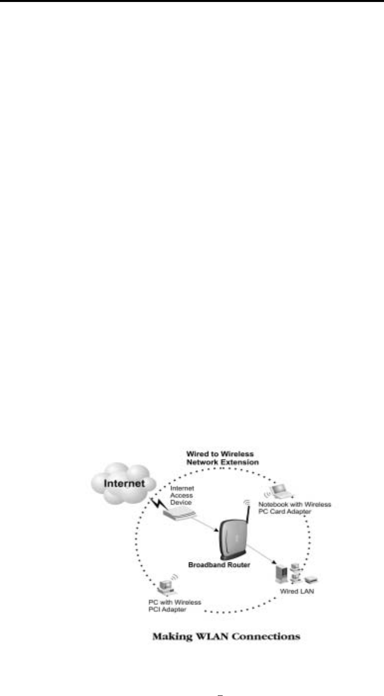
802.11a/g Router Applications
Accessing the Internet
The most common use of the 802.11a/g Router is to provide shared Internet access to allow everyone
on your LAN to surf the web and send/receive emails or files. The 802.11a/g Router can automatically
acquire a public IP address when connecting to the Internet. In turn, it will automatically assign IP
addresses to PCs (requesting DHCP client devices) on your LAN - you don’t have to apply for and
assign IP addresses to PCs on your network.
Accessing Servers from the Public Network
If you want special servers to be accessible to remote users across the Internet (e.g., an e-mail server, an
FTP server, or a web server), you can configure the 802.11a/g Router to proxy the service using its
(public) IP address. It means a remote user can access the server by using the 802.11a/g Router’s IP
address. Upon receiving a request, the 802.11a/g Router will re-direct the request to the actual server
on your local network.
Operating as an Access Point
Additionally, the Wireless Router can also be configured as an Access Point, and acts as the central
point of your local wireless network supporting a data rate of up to 108 Mbps. It allows client devices
on your wireless network to access the Internet, to communicate with other wireless devices on your
wireless network, or to communicate with devices on your wired LAN network.
Since 802.11g is based on the same 2.4GHz radio band as the 802.11b technology, the 802.11a/g
Router can inter-operate with existing 11Mbps 802.11b devices. Therefore you can protect your
existing investment in 802.11b client cards, and migrate to the high-speed 802.11g standard as your
needs grow. Alternatively, you can configure the 802.11a/g Router to provide an 802.11a WLAN
environment.
5

A Security Overview
More and more people are concerned about protecting your local network from the Internet. The
802.11a/g Router provides several ways to keep your network secure:
Devices on your wired or wireless network are assigned private IP addresses; therefore remote
users from the Internet cannot see nor access them. This provide a firewall between your local
LAN and the Internet.
The 802.11a/g Router implements IP packet filtering with SPI (Stateful Packet Inspection)
capabilities, which you can use to selectively filter (discard) packets to/from the Internet.
You can selectively restrict management to remote devices.
To address the growing security concern in a wireless LAN environment, different levels of security
can also be enabled in the 802.11a/g Router, including:
To disable SSID broadcast so to restrict association to only client stations that are already pre-
configured with the correct SSID.
To enable WEP (Wireless Encryption Protocol) encryption to implement privacy of your data
Support of Access Control List to allow you to grant/deny access to/from specified wireless
stations (using MAC addresses)
Provisioning of centralized authentication through 802.1x and RADIUS Server(s).
To enable WPA (WiFi Protected Access) to assure authorized access as well as to implement
privacy of your data. WPA comes with two modes: 802.1x for enterprise users and PSK (Pre-
Shared Key) for SOHO users.
802.11a/g Router Features
Compliant with 802.11a, 802.11b, and 802.11g standards with roaming capability
Support of NAT for multiple users to share Internet access
IP routing (RIP1/RIP2) support
VPN (Virtual Private Network) support for PPTP/IPSec pass-through.
Support of PPPoE (multiple sessions and unnumbered IP) and PPTP client function for
xDSL connections
Support of multimedia applications (NetMeeting, CUSeeMe, Quick Time, etc) pass-through.
Support of the Virtual Server function.
Support of the standard Access Point mode for connection to wireless clients
Built-in DHCP server to assign IP addresses to DHCP client devices on both wired and
wireless LAN
6

802.11a/g Router User’s Guide
Multiple security measures: to enable IP packet filtering, to disable SSID broadcast, to define
Access Control List, to enable WEP based encryption (up to 152 bits), to enable WPA, plus
the enhanced security with 802.1x using a primary and a backup RADIUS Server
Extensive monitoring capability such as event logging, traffic/error statistics monitoring
Easy configuration and monitoring through the use of a Web-browser based GUI (only
support IE6.0 or above) or SNMP commands from a remote SNMP management station
Setup Wizard for easy configuration/installation
Setting Up the device
The 802.11a/g Router can be managed by a local PC on either the wired or wireless LAN network. To
do this, the 802.11a/g Router must have an IP address, which can be statically configured, or is
dynamically obtained from a DHCP server on the LAN. For reasons to be given in Chapter 3, static IP
address assignment is much preferred.
7

Installing the 802.11a/g Router
This section describes the installation procedure for your 802.11a/g Router. It starts
with a summary of the content of the package you have purchased, followed by steps of how to
connect and power up your 802.11a/g Router. Finally, it describes how to configure a Windows PC to
communicate with your 802.11a/g Router.
C
h
apte
r
2
What’s in the Box?
The 802.11a/g Router package comes with the following items:
One 802.11a/g Router
One 5V DC/2A power adapter with a barrel connector
One Category-5 LAN cable with RJ-45 connectors
One copy of the 802.11a/g Router User’ Guide
8
802.11a/g Router User’s Guide
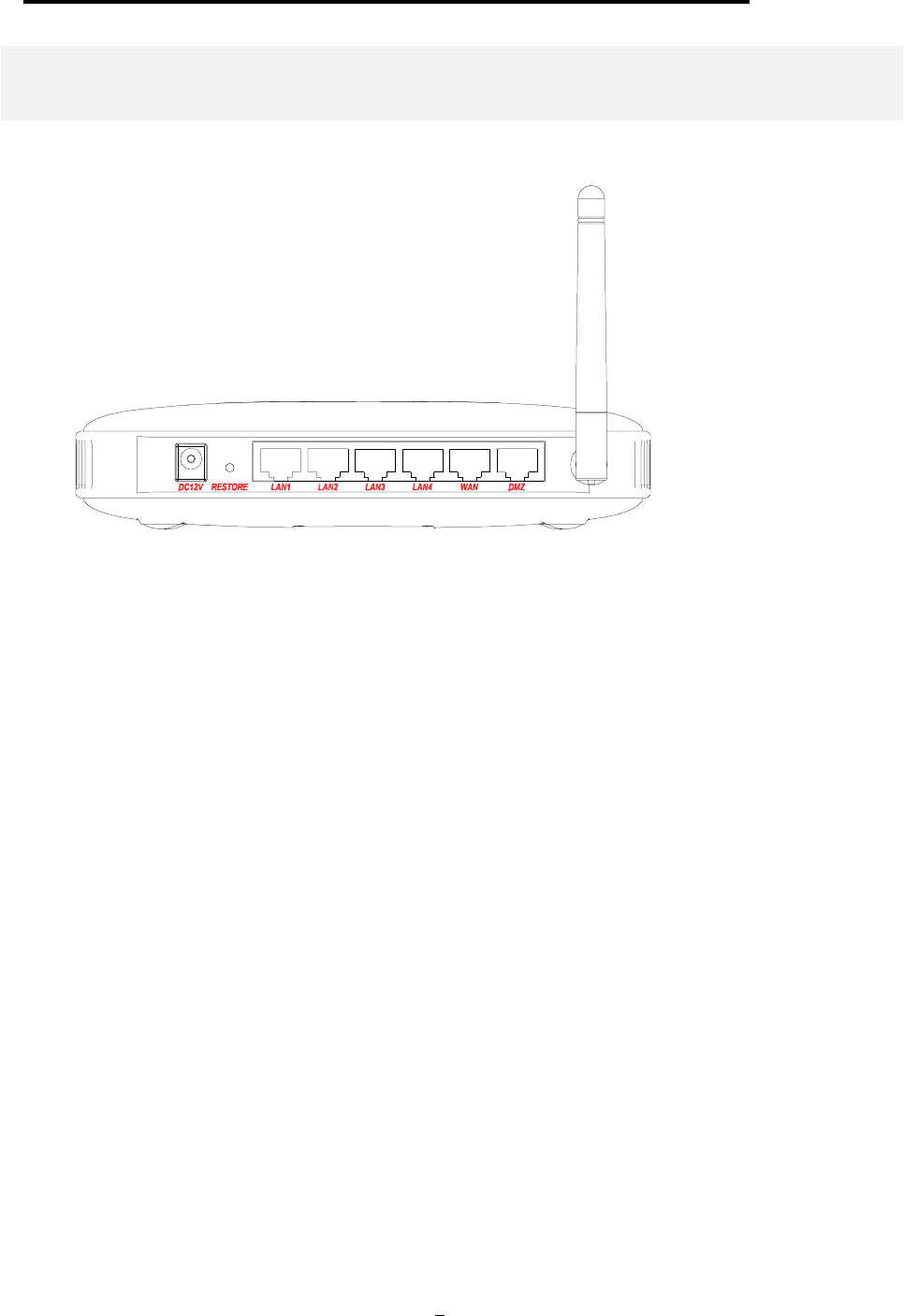
A physical look at the back panel
The following illustration shows the rear panel of Wireless Router.
(1) 4 RJ-45 10/100 Switch connectors for connecting to PCs and workstations or connecting
external Ethernet hub, or switch with auto-sensing.
(2) 1 RJ-45 WAN connector for connecting to Internet via ADSL/Cable modem
(3) 1 RJ-45 DMZ connector for connecting to an internal DMZ network or a PC
(4) 1 5V DC/2A power connector for connecting through a DC power adapter (included as part
of the product) to the wall power outlet
(5) 1 Restore button to restore the device back to the factory settings
9
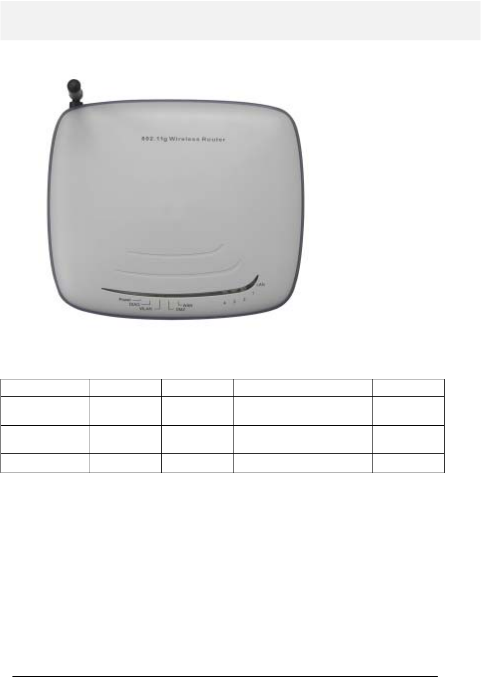
A physical look at the front panel
The LEDs on the front of the 802.11a/g Router reflect the operational status of the unit.
802.11a/g Router LED Description
Label LAN WAN/DMZ WLAN DIAG POWER
Steady Green Link is active Link is active Link is active 3 seconds after
powered on Power
OFF No LAN
connection No connection No Wireless
connection Checked OK No Power
FLASH XMT/RCV Data XMT/RCV Data XMT/RCV Data N/A N/A
10
802.11a/g Router User’s Guide
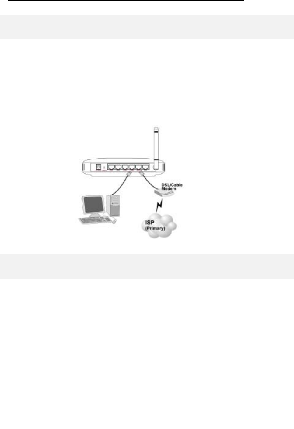
Connecting the Cables
Follow these steps to install your 802.11a/g Router:
Step 1 Connect ADSL/Cable modem to the Wireless Router WAN port using CAT5 UTP
LAN cable.
Step 2 Connect a PC/Workstation to one of the LAN ports of the Wireless Router, such as
port 1 or port 2.
Step 3 Connect the DC adapter to the Wireless Router and an electrical outlet.
High Level Configuration Steps Required for the 802.11a/g Router
This section describes configuration required for the 802.11a/g Router before it can work properly in
your network.
Normally, devices on a LAN (except for servers) are configured to obtain their IP addresses
automatically. Depending on whether there is a separate DHCP server available in your LAN
environment network, thus to determine if you need to enable the built-in DHCP server in the
Wireless Router. The following configuration step assumes that the router’s built-in DHCPS will be
used.
Additionally, since you need to perform various configuration changes to the 802.11a/g Router,
including the SSID, Channel number, the WEP key, …, etc., it is necessary to associate a fixed IP
address with the 802.11a/g Router, which is why the 802.11a/g Router will be shipped with a factory
default private IP address of 192.168.1.1 (and a network mask of 255.255.255.0).
11

Setting up a Windows PC or wireless client as DHCP clients
The following will give detailed steps of how to configure a PC or a wireless client to “obtain IP
addresses automatically”. For other types of configuration, please refer to the corresponding user
manual.
For the case of using a LAN attached PC, the PC must have an Ethernet interface installed properly,
be connected to the 802.11a/g Router either directly or through an external LAN switch, and have
TCP/IP installed and configured to obtain an IP address automatically from a DHCP server in the
network.
For the case of using a wireless client, the client must also have a wireless interface installed properly,
be physically within the radio range of the 802.11a/g Router, and have TCP/IP installed and
configured to obtain an IP address automatically from a DHCP server in the network.
Configuring a PC running MS-Windows 95/98/Me:
1. Click the Start Button, and select Settings.
2. Click the Control Panel. The Win95/98/Me Control Panel will appear.
3. Open the Network setup window by double-clicking the Network icon.
4. Check your list of Network items. If TCP/IP is already installed, proceed to step 5. Otherwise:
(You may need your Windows CD to complete the installation of TCP/IP.)
Click the ADD button.
In the Network Component Type dialog box, select Protocol.
In the Select Network Protocol dialog box, select Microsoft.
In the Network Protocols area of the same dialog box, select TCP/IP and click OK.
5. With TCP/IP installed, select TCP/IP from the list of Network Components.
6. In the TCP/IP window, check each of the tabs and verify the following settings:
Bindings: Select Client for Microsoft Networks and Files and printer sharing for Microsoft
Networks
Gateway: All fields are blank.
DNS Configuration: Select Disable DNS.
WINS Configuration: Select Use DHCP for WINS Resolution.
IP address: Select the Obtain IP address automatically radio button.
7. Reboot the PC.
Configuring a PC running MS-Windows XP/2000:
1. Click the Start button, and choose Control Panel (in Classic View).
2. In the Control Panel, double-click Network Connections.
3. Double-click Local Area Connection.
4. In the LAN Area Connection Status window, select Internet Protocol (TCP/IP) and click
Properties.
5. Select the Obtain an IP address automatically and the Obtain DNS server address automatically
radio buttons.
12
802.11a/g Router User’s Guide
6. Click OK to finish the configuration.
Confirming your PC’s IP Configuration:
There are two tools useful for finding out a computer's IP address and default gateway:
WINIPCFG (for Windows 95/98/Me) Select the Start button, and choose Run. Type winipcfg, and a
window will appear listing the IP configuration. You can also type winipcfg in the MS-DOS prompt.
The procedure required to set a static IP address is not too much different from the procedure
required to set to “obtain IP addresses dynamically” - except that at the end of step 7, instead of
selecting “obtain IP addresses dynamically, you should specify the IP address explicitly.
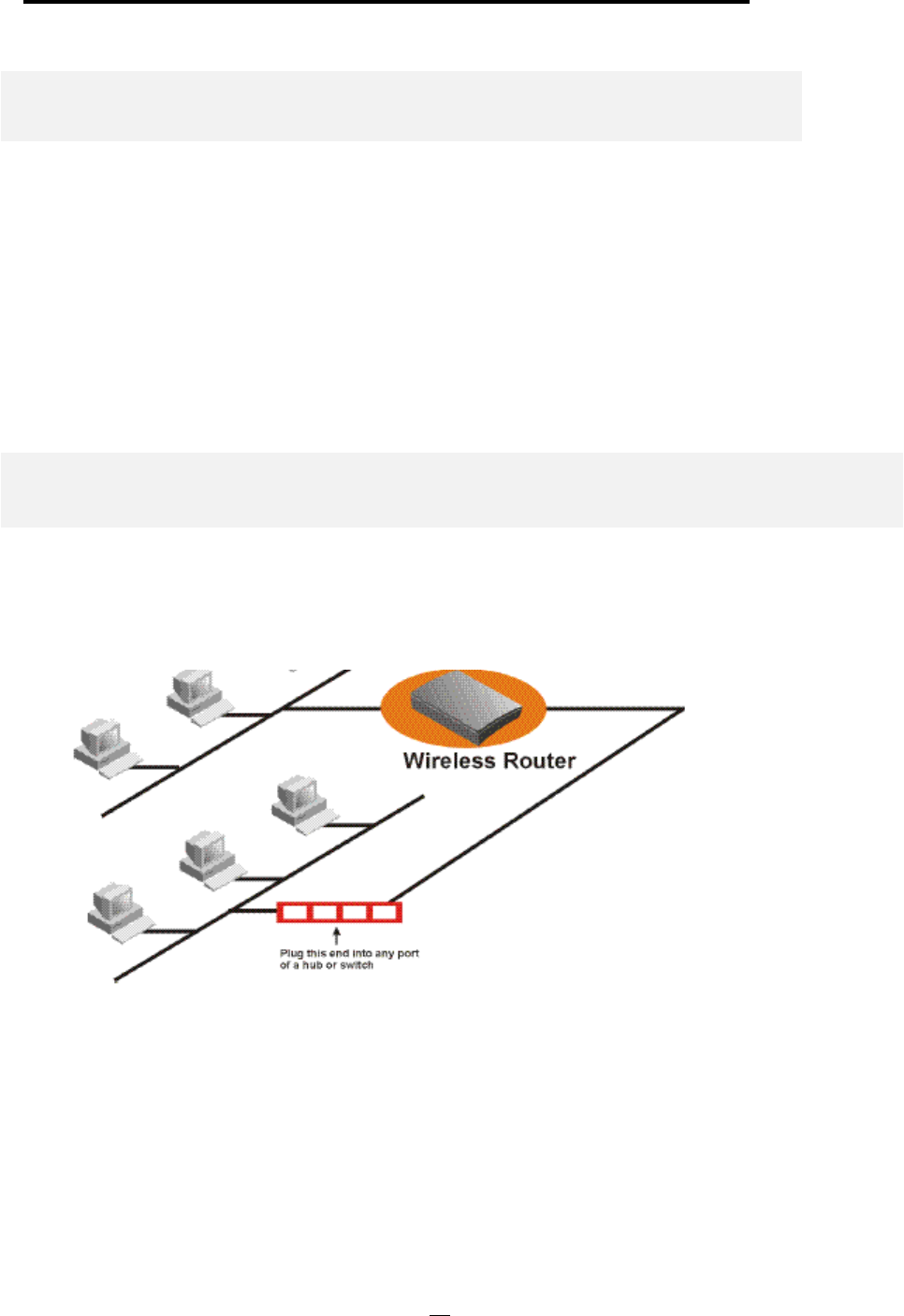
Connecting More Devices Through A Switch/Hub To The 802.11a/g Router
The Wireless Router provides four LAN ports to allow up to four PCs or Workstations to be
connected to it directly. If you want to connect more devices, you can connect an external hub or
switch to any of the LAN ports using a LAN cable.
13
Basic Configuration of the 802.11a/g Router
This section contains basic configuration procedure for the 802.11a/g Router. It
describes how to set up the 802.11a/g Router for Internet Access operation, and
how to set up the LAN configuration.
The 802.11a/g Router is designed so that all basic configuration may be easily invoked through the a
standard Web browser such as Internet Explorer. Currently only the Internet Explorer 6.0 (or above) is
supported.
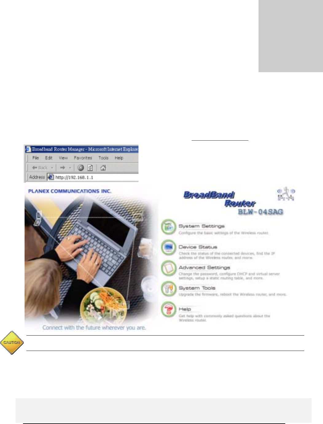
To access the WLAN 11a/g Router’s management interface for the first time, enter the default IP
address of the WLAN 11a/g Router in your Web browser http://192.168.1.1/.
14
Note: The IP address of your PC must be in the same IP subnet as the 802.11a/g Router. It is preferred that you
configure the PC to obtain an IP address automatically from the 802.11a/g Router.
The Home Page of the 802.11a/g Router screen will appear, with its main menu displayed on the
screen, showing the following top-level choices: Setup Wizard, Device Status, System Tools,
Advanced Settings, and Help. Selecting any will allow you to navigate to other configuration menus.
Logging On
C
h
apte
r
3

802.11a/g Router User’s Guide
When you attempt to access a configuration screen from the browser menu, an administrator login
screen will appear, prompting you to enter your password to log on. Once you are logged in, you will
not be asked to log in again unless your “session” expires such as due to inactivity timeout.
If you are logging in for the first time after you received your 802.11a/g Router, you should use the
factory default password, “password” to log in. (You should change it as soon as after you log in.)
Characters you type (as your password) will be echoed back as a string of asterisks (“*”) for security
reasons. After you enter the password, clicking the LOG ON button will begin the password
verification process and, if successful, your configuration session can begin.
Note: Should there be no settings or access on the web management screen, system will logout
automatically in 10 minutes.
Setup Wizard
The Setup Wizard will guide you through a series of configuration screens to set up the basic
configuration of your 802.11a/g Router. At the end of the Setup Wizard screens, you should press the
“finish” button, and all your configuration modifications will take effect.
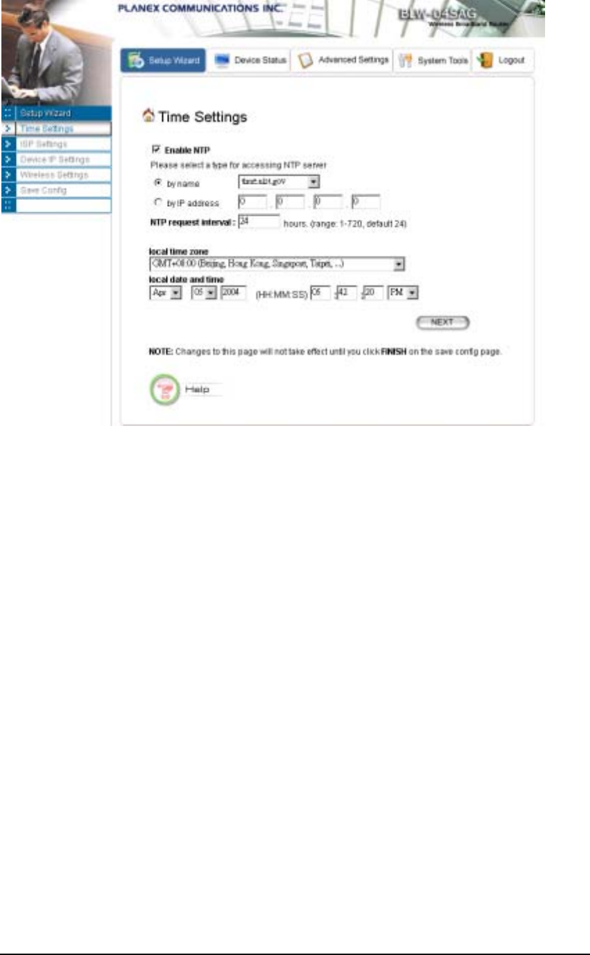
SETTING UP YOUR LOCAL TIME ZONE AND DATE/TIME
After logging in, the Time Settings page appears. The router time will first be set to the local time of
the PC (on which the browser is running). If this time is not correct, modify the appropriate fields as
necessary, and then click “NEXT”.
Since the device does not have a real time clock on it, the system time needs to be set every time the
device is booted up. You can enable the NTP (Network Time Protocol) function, which will set the
system time periodically to the time queried from the NTP server configured. You can specify the
NTP server to be queried either by selecting a well-known server or by entering the IP address of the
server. The 802.11a/g Router will query the configured NTP server for the current time periodically
according to the NTP request interval configured.
15
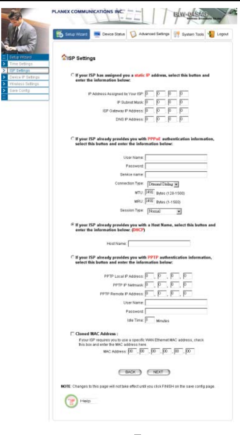
CONFIGURE THE ISP PROFILE
In the following configuration screen, as with the usual convention, radio buttons are used to
make a selection when only one out of multiple mutually exclusive choices can be selected, while
square check boxes can be used to select multiple non-mutually-exclusive choices.
When configuring the device for Internet access, decide which one of the following multiple
choices to select (through radio buttons):
1. You can use a static IP address provided by your ISP to connect to the Internet. In this case,
you need to configure the following information:
• IP Address Assigned by your ISP: the IP address of the WAN interface of your router.
• IP Subnet Mask: the IP subnet mask of the WAN interface of your router.
• ISP Gateway IP Address: the IP address of your ISP’s Gateway.
• DNS IP Address: the IP address of the DNS server.
2. You use the user name and password assigned by your ISP to connect to the Internet
(required for the underlying PPPoE protocol). In this case, you need to configure the
following information:
• User name: the username of your ISP account.
• Password: the password of your ISP account.
16

802.11a/g Router User’s Guide
• Service Name: the service name of your ISP account
• Connection Type: There are 3 options for this option.
Always on: the connection is always on no matter there is traffic or not. If the connection
is lost (e.g. the PPPoE server is down or the ADSL/Cable line is disconnected), the
connection will be brought up right after the connection is recovered.
Demand Dialing: the connection will be brought up only when there is traffic. That is, it
requires an outgoing packet to trigger the connection.
Manually: the connection will not be brought up until you manually connect it at the
WAN Status page (described in How To View The Device Status section).
• MTU/MRU: This is to set the values of MTU (Maximum Transmit Unit) and MRU
(Maximum Receive Unit) that is used between the 802.11 a/g Router and the ISP device
at the other side. Users are not encouraged to change these values unless you know what
you are doing.
• Session Type: There are 3 options for this setting.
Normal: This option only supports one PPPoE session.
Unnumbered Link: This option can let your LAN be a public IP subnet. That is, PC’s on
the LAN can be configured with public IP addresses provided by your ISP. You can put
your own servers on the LAN, and then people on the Internet can access these servers.
The source IP address of the traffic from these PC’s to the Internet is not modified (i.e.
NAT is not applied) either. If you still want to keep a private LAN, you can check the
Maintain Private LAN setting and enter the IP Address and IP Subnet Mask of your
private LAN. If you do not keep a private LAN, the “Device IP Settings” menu at the left
side will disappear.
Multiple PPPoE: You can define more than one PPPoE sessions by using this option.
The primary session is configured at the ISP Settings page, and other sessions are
configured at the Multiple PPPoE page.
3. You use DHCP to connect to the Internet (most likely through a cable modem connection).
In this case, your ISP may require you to configure the Host Computer Name:
• Host Name: The Host Name provided by your ISP.
4. You use PPTP to connect to the Internet. In this case, your ISP requires you to configure
PPTP's tunnel IP address, the username, and password. In this case, configure the static IP
address as in the above and then configure the following information:
• PPTP Local IP Address: the IP address on the local side of the PPTP tunnel provided
by your ISP.
• PPTP IP Netmask: the Netmask on the local side of the PPTP tunnel provided by your
ISP.
• PPTP Remote IP Address: the IP address of the remote side of the PPTP tunnel
provided by your ISP.
• User Name: the username of your ISP account.
• Password: the password of your ISP account.
17

• Idle time: The Idle Timeout is the number of seconds of "inactivity" before the PPTP
connection is taken down.
Its value should be between 0 to 60 minutes, with 5 (minutes) being the default value, and
0 meaning the connection will never time out.
Cloned MAC Address: Some ISPs expect a PC to be connected to their service, and use the MAC
address of this PC’s LAN card for identification purposes. By checking the following “Cloned MAC
address” square check box, your 802.11a/g Router allows a MAC address to be configured and
“cloned” in the router to simulate a PC.
If the device is a PC based on WIN 95/98/Me, you can run winipcfg to find out the MAC Address
of its LAN card. If the device is a PC based on WIN 2000/NT/XP, you need to run "ipconfig/all"
to find out the MAC address of its LAN card.
18
802.11a/g Router User’s Guide
19
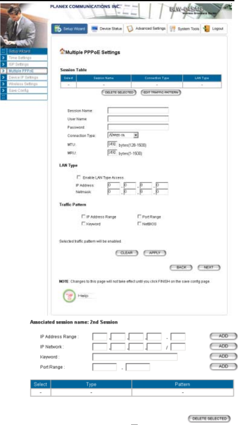
MULTIPLE PPPOE SETTINGS
If you have selected PPPoE with Multiple PPPoE type at the ISP Settings page, you will see the
Multiple PPPoE settings page where you can add more PPPoE sessions.
For each PPPoE session, you have to assign a mnemonic name and configure similar settings as in the
primary session. In addition, you can configure LAN Type and Traffic Pattern in order to use an added
session.
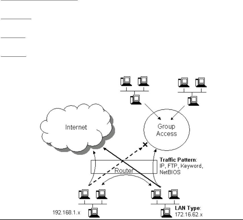
LAN Type: If you enable LAN Type, you can have another subnet on your LAN environment.
Some ISP provides Group Access function that gives you a subnet to assign on your LAN
environment, and ISP will make all such subnets belonging to the same Group connected
together. A PC on such subnets can reach other PCs on the Internet within the same Group
through the session configured without NAT; it also can do the normal Internet access through
the primary PPPoE session.
Traffic Pattern: You have to configure traffic pattern(s) in order to use PPPoE sessions other
than the primary session. Any outgoing packet matching one of the traffic pattern configured will
be sent out using the corresponding PPPoE session. There are four types of traffic patterns that
you can use. After you checked a traffic pattern and clicked the APPLY button you have to
configure the details by selecting the item in the Session Table and click the EDIT TRAFFIC
PATTERN button.
IP Address Range/Network: Packets with destination IP address within the range or network
configured are matched.
Port Range: TCP/UDP packets with the source or destination port in the configured range are
matched.
Keyword: IP packets with a payload containing a string matching the configured keyword are
matched.
NetBIOS: NetBIOS packets are matched.
Multiple PPPoE usage can be well illustrated by the following diagram.
20
802.11a/g Router User’s Guide
21
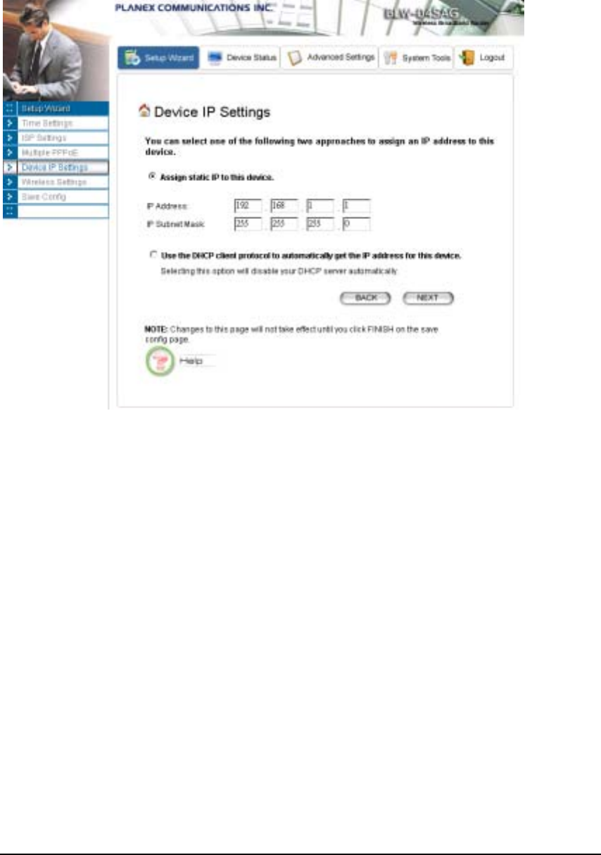
DEVICE IP SETTINGS
The Device IP setting screen allows you to configure the IP address and subnet mask of your
802.11a/g Router: you can configure a static IP address and a subnet mask, or configure it to obtain an
IP address and a subnet mask automatically from a DHCP server on the local network.
If you choose to assign a static IP address manually, check the button that says, “Assign static IP to
this device” and then fill in the following fields
IP Address and IP Subnet Mask: These values default to 192.168.1.1 and 255.255.255.0, respectively.
This IP address can be modified if necessary, to either a different address in this same subnet or to an
address in a different subnet.
When you modify it, if the DHCP server function of your 802.11a/g Router is enabled, the pool of
IP addresses it will use for assignment purposes will also be automatcailly adjusted accordingly. For
example, if the default IP address is used, the IP address pool for assignment consists of addresses
from 192.168.1.2 to 192.168.1.254. However, please do not change the default IP address unless
you know exactly what you want to achieve.
Then you should press Next to get to the next screen.
If you choose to use an external DHCP Server to automatically assign an IP address to your 802.11a/g
Router, check the button that says, “Use the DHCP protocol to automatically get the IP address
for this device”, and then press Next to the next screen.
When an IP address is dynamically assigned to the router, its value can change depending on the IP
address assignment policy used by the DHCP server in the network. Since you need to use an IP
address to control and manage your 802.11a/g Router, without the knowledge of its IP address, in
22

802.11a/g Router User’s Guide
order to access it, you will need to use UPnP (Universal Plug and Play) or other management tools that
do not depend on a fixed IP address.
It is strongly recommended that you select the manual static IP address.
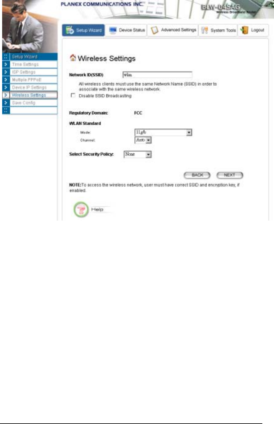
CONFIGURE YOUR WIRELESS LAN CONNECTION
In the following configuration screen, you can configure wireless related parameters of your
802.11a/g Router:
Network Name (SSID): The SSID is the network name used to identify a wireless network. The
SSID must be the same for all devices in the wireless network. Several Routers on a network can have
the same SSID. The SSID can be up to 32 characters long. This SSID is used for both radios (i.e.
802.11a and 802.11 b/g).
Disable SSID Broadcasting: An access point periodically broadcasts its SSID, along with other
information, which allows client stations to learn its existence while searching for Routers in the
wireless network. Select Disable if you do not want the device to broadcast the SSID.
Regulatory Domain: This place shows the regulatory domain where the device is running. This field
cannot be changed by regulation.
WLAN standard: Here you can set the configuration for the radio.
Mode: You can select the radio to run the 802.11b/g (mix mode – allowing both 802.11b and 802.11g
to co-exist), 802.11g only, 802.11g turbo, super g without turbo, super g with dynamic turbo,
super g with static turbo, 802.11a, 802.11a turbo, super a without turbo, super a with dynamic
turbo, or super a with static turbo protocol (the turbo mode is only applied where the regulation
allows).
Channel: Select the channel from the available list to match your network settings. All devices in the
wireless network must use the same channel and share the total bandwidth available.
Note: The available channels are different from country to country and for different WLAN mode.
Security Policy: You can select different security policy to provide association authentication and/or
data encryption.
23
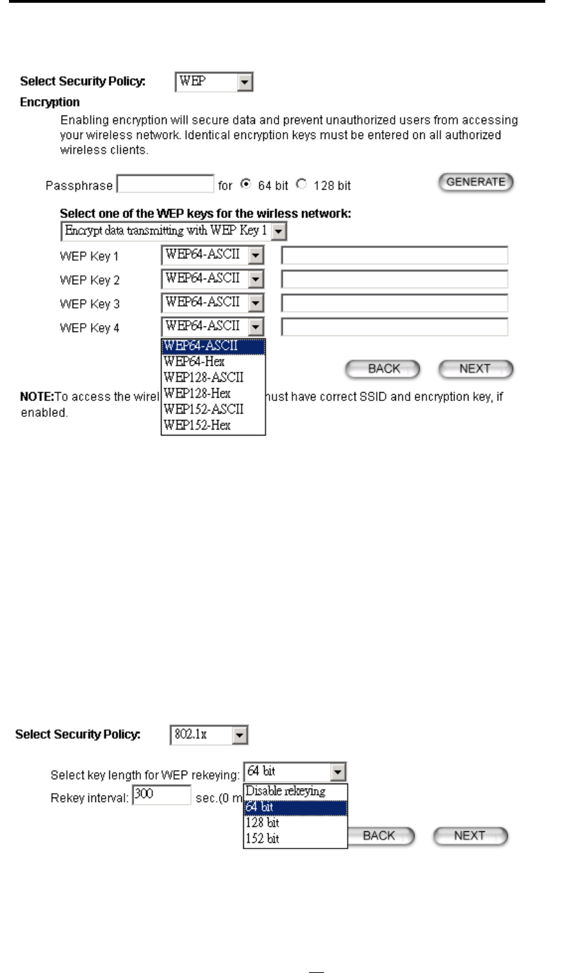
WEP
You can use WEP encryption to protect your data when you are transmitting data in the wireless
network. There are 3 types of keys: 64 (WEP64), 128 (WEP128), and 152 (WEP152) bits. You can
configure up to 4 keys using either ASCII or Hexadecimal format.
Key Settings: For WEP64 and WEP128, you can enter a “Passphrase” (a key of up to 32
alphanumerical characters), choose 64-bit, and press the Generate button to generate four WEP64
keys in the entries below, or choose 128-bit, and press the Generate button to generate one WEP128
key in the first entry.
Alternatively, and for WEP152, you can manually configure each of them.
When you manually configure a key, the length for a WEP64 key must be equal to 5, for a WEP128
key it must be equal to 13, and for a WEP152 key it must be equal to 16. Once you enable the WEP
function, please make sure that exactly the same WEP key is configured in both the Wireless Router
and client stations.
You can define a key using ASCII or hex characters. A WEP128 ASCII key looks like "An ASCII key!"
(13 characters), while a WEP64 hex key looks like "44-12-24-A8-B2" (5 bytes) and “11-22-33-44-55-
66-77-88-99-00-A3-BB-2C” as WEP128 hex key. Each set of hexadecimal numbers should be
separated by “-“(dash).
24
802.11a/g Router User’s Guide
Key Index: You have to specify which of the four keys will be active.
Please note that some Wireless Client Cards allow hexadecimal characters only.
802.1x
IEEE 802.1x is an IEEE standard which is based on a framework that involves stations to be
authenticated (called Supplicant), an authentication server (a RADIUS Server) that provides
authentication services, and an authenticator that provides necessary translation and mediating
functions between the authentication server and stations to be authenticated, in this case your
802.11a/g Router.
During EAP authentication, the 802.11a/g Router relays authentication messages between the
RADIUS server and clients being authenticated.
802.1x allows users to leverage a RADIUS server to do association authentications. You can also
enable dynamic WEP keys (64, 128, 152-bit) to have data encryption. Then you do not have to enter
the WEP key manually because it will be generated automatically and dynamically.
Note: After you have finished the configuration wizard, you have to configure the Radius Settings in
Advanced Settings in order to make the 802.1x function work.
WPA-PSK
Wi-Fi Protected Access (WPA) with Pre-Shared Key (PSK) provides better security than WEP keys. It
does not require a RADIUS server in order to provide association authentication, but you do have to
25
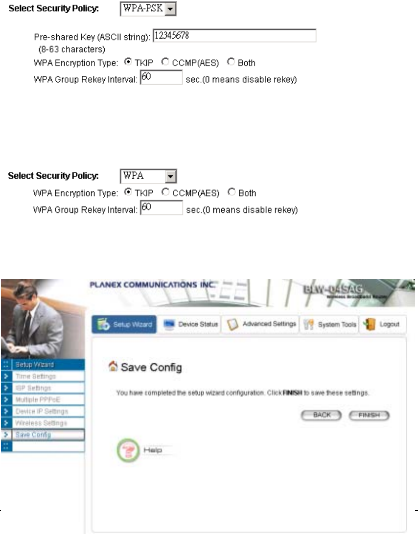
enter a shared key for the authentication purpose. The encryption key is generated automatically and
dynamically.
Pre-shared Key: This is an ASCII string with 8 to 63 characters. Please make sure that the 802.11a/g
Router and the wireless client stations use the same key.
Encryption Type: There are two encryption types TKIP and CCMP (AES). While CCMP provides
better security than TKIP, some wireless client stations may not be equipped with the hardware to
support it. You can select Both to allow TKIP clients and CCMP clients to connect to the Access
Point at the same time.
Group Rekey Interval: A group key is used for multicast/broadcast data, and the rekey interval is
time period that the system will change the group key periodically. The shorter the interval is, the better
the security is. 60 seconds is a reasonable time, and it is used by default.
WPA
Wi-Fi Protected Access (WPA) requires a RADIUS server available in order to do authentication (same
as 802.1x), thus there is no shared key required.
The Encryption Type and Group Rekey Interval settings are same as WPA-PSK.
FINISH SETUP WIZARD AND SAVE YOUR SETTINGS
After stepping through the Wizard’s pages, you can press the FINISH button for your modification to
take effect. This will also cause your new settings to be saved into your system permanently.
26

802.11a/g Router User’s Guide
Alternatively, you can also click the “Back” button to go back to previous configuration screens for
more changes.
Note: If you change the router’s IP address to a different IP network address space, as soon as you click on
FINISH you will no longer be able to communicate with your 802.11a/g Router. You need to change your
IP address and then re-boot your computer in order to resume the communication.
27

C
h
apte
r
4
Advanced Settings
This section contains advanced setting procedures for the 802.11a/g Router. It describes modifications
that normally you may not need for basic system operation. One exception is changing your password:
it is highly recommended that you change the default factory setting as soon as you start to use your
802.11a/g Router.
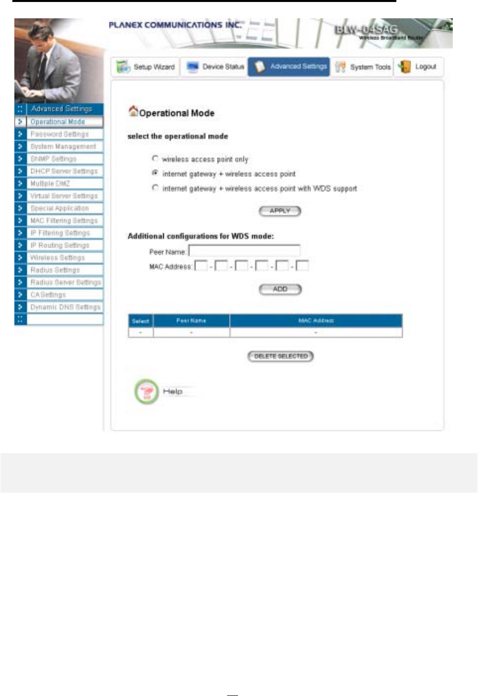
Operational Mode
Before you start to use the device, you need to select the operational mode to be wireless AP only
or both Internet gateway and wireless AP:
Wireless Access Point only: When this is selected, the router operates in the AP-only
Mode, and connects Wireless Client Users to the Ethernet (WAN).
Internet Gateway + Wireless Access Point: When this is selected, the router will function
as an Internet access sharing device as well as a wireless AP.
Internet Gateway + Wireless Access Point with WDS Support: When this is selected,
the router will function as an Internet access sharing device as well as a wireless AP, plus the
mode to participate in the wireless distribution system. This could broaden the WLAN
scope across several AP’s. You should add all the WDS participants' MAC addresses with a
mnemonic name in addition.
When adding a WDS participant, you also have to select the radio (i.e. Radio1 or Radio2) that the
participant will be connected with.
28
802.11a/g Router User’s Guide
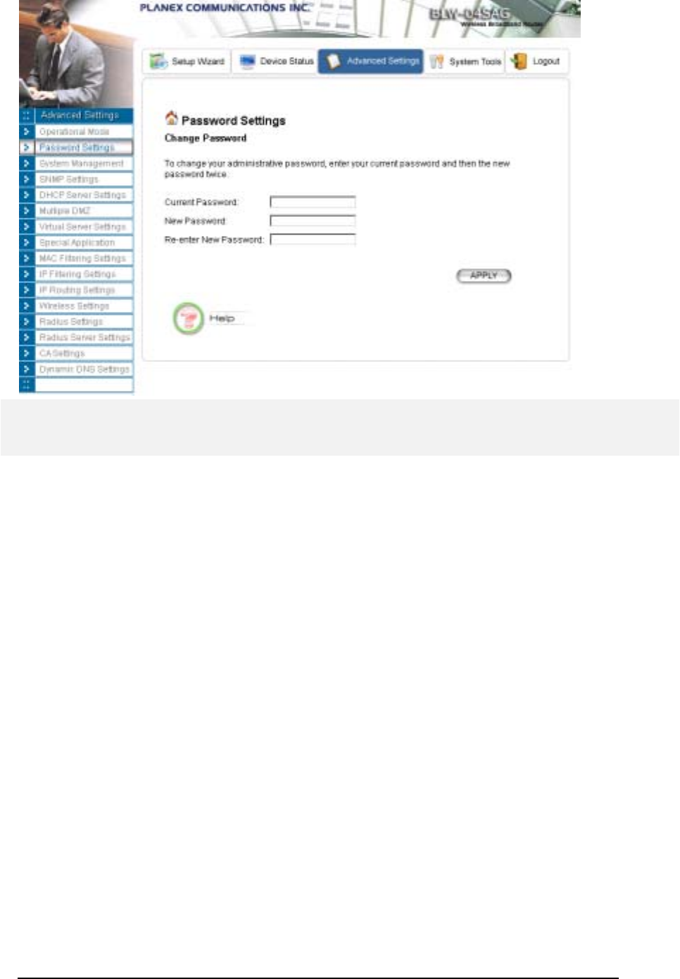
Password Settings
Your 802.11a/g Router comes with a default factory password of “password”. After you start using
the router, you should change the default password.
To change the password, press the Password Settings button to enter the Password Settings screen,
enter the current password followed by the new password twice. The entered characters will appear as
asterisks.
If you forgot the password, the only way to recover it is to return the device to its default state as
shipped from the factory. To restore the password to the default password, please refer to the
section, "What if I forgot the Password?" in the user manual.
29
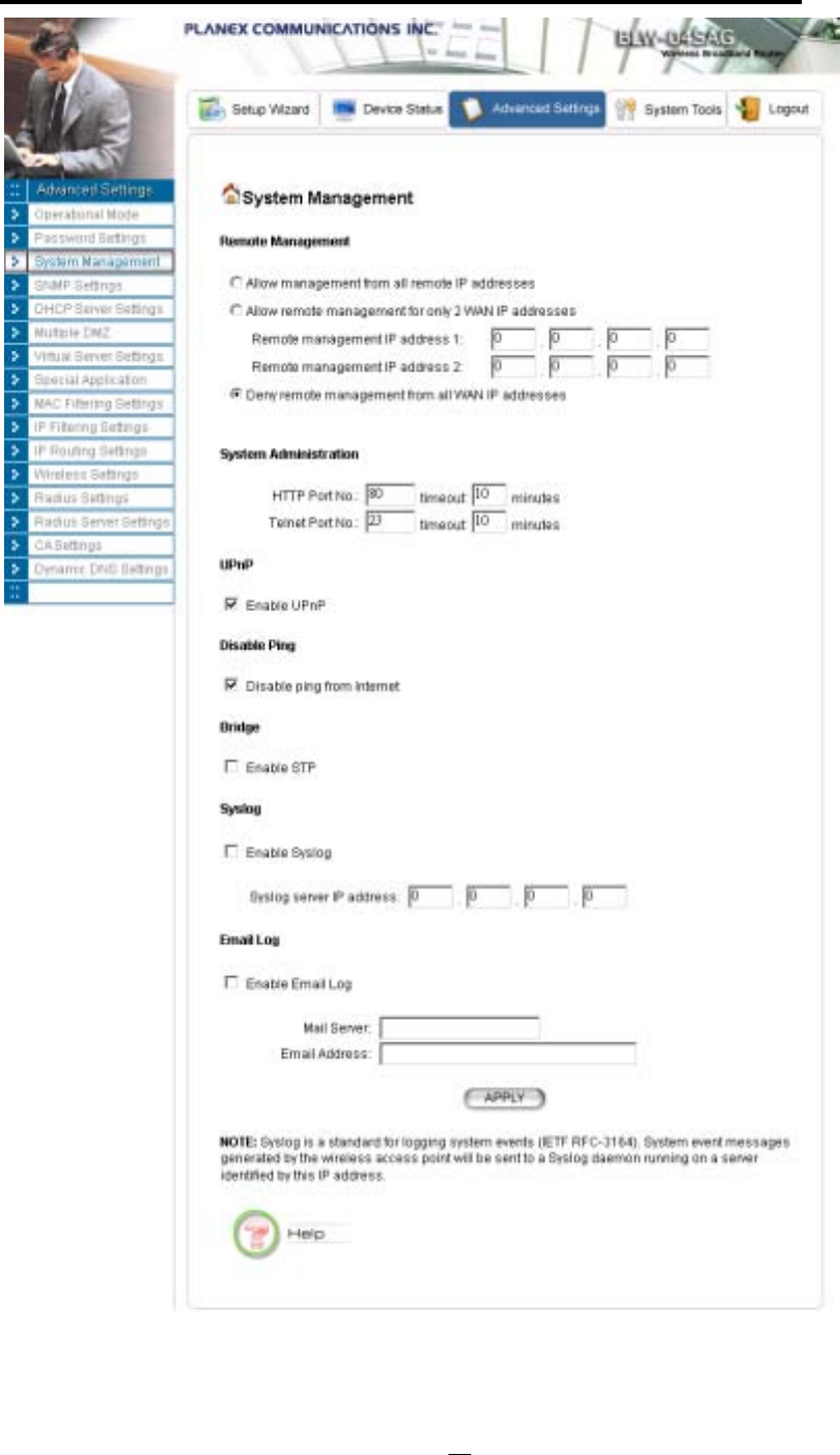
System Management
Clicking the System Management button allows system related parameters to be configured for the
802.11a/g Router.
Remote Management: The remote management feature allows you to manage your 802.11a/g
Router remotely through the use of an HTTP browser.
The system allows you to (1) allow remote management from all WAN IP addresses, to (2) allow
remote management from up to two WAN IP addresses, or to (3) disallow remote
management from any WAN IP addresses.
System Administration: The router allows you to designate special port numbers other than the
standard 80 for http for remote management. It also allows you to specify the duration of idle time
(inactivity) before a web browser session times out. The default time-out value is 10 minutes.
UPnP: The router's Universal Plug and Play (UPnP) feature allows a Windows XP/ME PC to
discover the router and automatically show an icon in the task bar on the screen. You can double-click
the icon to access the router directly (without having to specify its IP address).
Disable Ping: "Ping" is a utility for testing the connectivity. Response to a ping can be disabled, such
as when you do not want the router to be accessed (e.g., attacked) from the Internet.
Bridge: You can enable/disable the 802.1d STP (Spanning Tree Protocol) function on the bridge of
WLAN and Ethernet (i.e. the LAN interface). Enable this function can detect loops in your LAN
environment and then protect the LAN from being saturated with infinite loop traffic.
30
802.11a/g Router User’s Guide
Syslog: Syslog is an IETF (Internet Engineering Task Force - the Internet standards body)-
conformant standard for logging system events (RFC-3164). When the 802.11a/g Router encounters
31

an error or warning condition (e.g., a log-in attempt with an invalid password), it will create a log in the
system log table. To be able to remotely view such system log events, you need to check the Enable
Syslog box, configure the IP address of a PC where a Syslog daemon is running in the background.
When doing so, the 802.11a/g Router will send logged events over the network to the PC for future
viewing.
Syslog server IP address: The IP address of the PC where the Syslog daemon is running.
Email Log: If the Email Log function is enabled, every system log message will be sent to the
configured email address through the configured mail server.
Mail Server: the mail server domain name that you use to send syslog emails.
Email Address: the email address that syslog emails will be sent to.
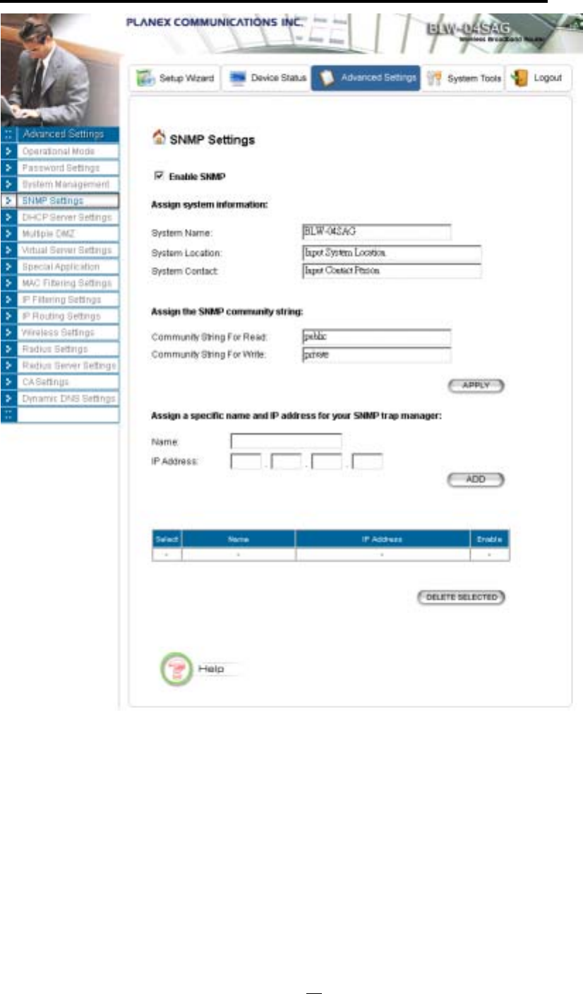
SNMP Settings
This screen allows you to configure SNMP parameters including the system name, the location and
contact information. Additionally, you can configure the 802.11a/g Router to send SNMP Traps to
remote SNMP management stations. Traps are unsolicited alert messages that 802.11g Router sends to
remote management stations.
32
802.11a/g Router User’s Guide
System Name: A name that you assign to your 802.11a/g Router. It is an alphanumeric string of up
to 30 characters.
System Location: Description of where your 802.11a/g Router is physically located. It is an
alphanumeric string of up to 60 characters.
System Contact: Contact information for the system administrator responsible for managing your
802.11a/g Router. It is an alphanumeric string of up to 60 characters.
Community String For Read: If you intend the router to be managed from a remote SNMP
management station, you need to configure a read-only “community string” for read-only operation.
The community string is an alphanumeric string of up to 15 characters.
33

Community String For Write: For read-write operation, you need to configure a write “community
string”.
A trap manager is a remote SNMP management station where special SNMP trap messages are
generated (by the router) and sent to in the network.
You can define trap managers in the system.
You can add a trap manager by entering a name, an IP address, followed by pressing the ADD
button.
You can delete a trap manager by selecting the corresponding entry and press the DELETE
SELECTED button.
You enable a trap manager by checking the Enable box in the corresponding entry or disable the trap
manager by un-checking the Enable box.
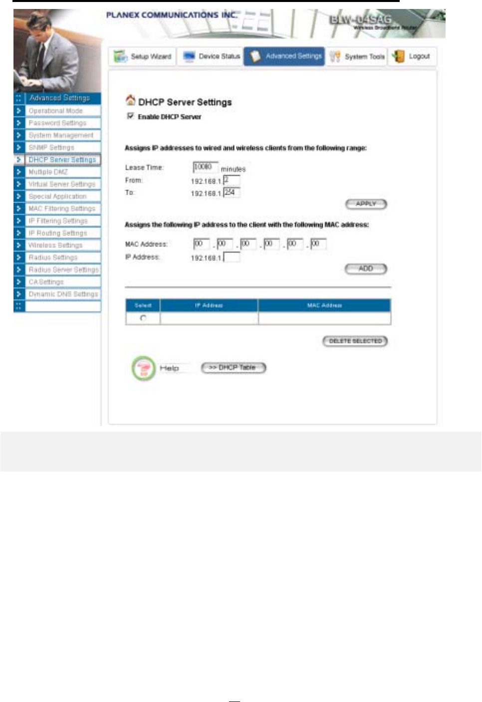
DHCP Server Settings
The DHCP server option allows the 802.11a/g Router to assign IP addresses to DHCP client devices
on your wired or wireless LAN to obtain IP addresses automatically.
If you want the Router to act as a DHCP server and assign private IP addresses to requesting
DHCP clients on the LAN, you need to check the Enable DHCP Server box.
You can select one of the following two ways to assign IP addresses:
Assigns IP addresses to wired or wireless clients from the following range:
When IP addresses are assigned to a requesting DHCP client, after the “lease time”, the
client is expected to renew the lease. Its default value is 10080 minutes.
The from and to range of IP addresses to be assigned to requesting DHCP clients can be
configured manually, with the default being 2 to 254.
After you enter the information, you should press APPLY.
Assigns the following IP address to the client with the following MAC address:
You can also specify the IP address to be assigned to a device with a pre-configured MAC
address.
You can add such a mapping by entering a MAC address, and the IP address to be assigned,
followed by pressing the ADD button. Up to 20 mappings can be added.
You can delete a mapping by selecting the corresponding entry and press the DELETE
SELECTED button.
DHCP Table: Press this button will cause the screen to jump to DHCP client table page.
34
802.11a/g Router User’s Guide
Multiple DMZ
The router supports one hardware DMZ port, multiple software DMZ ports, plus one default
DMZ port.
The hardware DMZ is implemented through the hardware: the router has a separate hardware
Ethernet port, to which multiple devices with public IP addresses assigned by the ISP can be
connected. Incoming data for these devices from the Internet will be sent by the router to the
hardware Ethernet port directly. No configuration would be required.
Both the default and multiple DMZ ports are implemented through software.
When the router receives incoming data from the Internet, it will search through an internal
address translation table to perform address translation function. If a match can be found, the
data will be forwarded to the corresponding device in your local LAN, otherwise the data will be
dropped or forwarded to the default DMZ if it is configured.
35
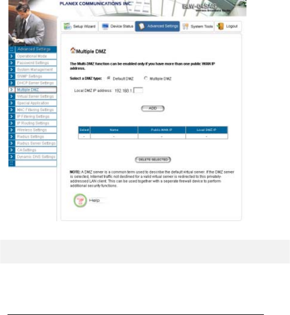
An additional feature is to allow devices with WAN IP addresses to be used by the Internet users
to access private devices in your local LAN. In this case, you need to configure the mapping
between the WAN IP address and the private IP address.
To add the default DMZ, you need to select “Default DMZ” and enter the local DMZ IP
address, followed by pressing the ADD button.
To add a device for multiple DMZ, first select “Multiple DMZ”, add a mnemonic name, a
public WAN IP address, and the local DMZ IP address on the LAN, followed by pressing the
ADD button.
You can delete a DMZ entry by selecting the corresponding entry and press the DELETE
SELECTED button.
Virtual Server Settings
A Virtual Server is a server built on a single or a cluster of real servers. A DMZ server is a term
commonly used to describe the default Virtual Server - the router will redirect all traffic from the
Internet without a valid port address mapping to this device. An HTTP server with a private IP
36
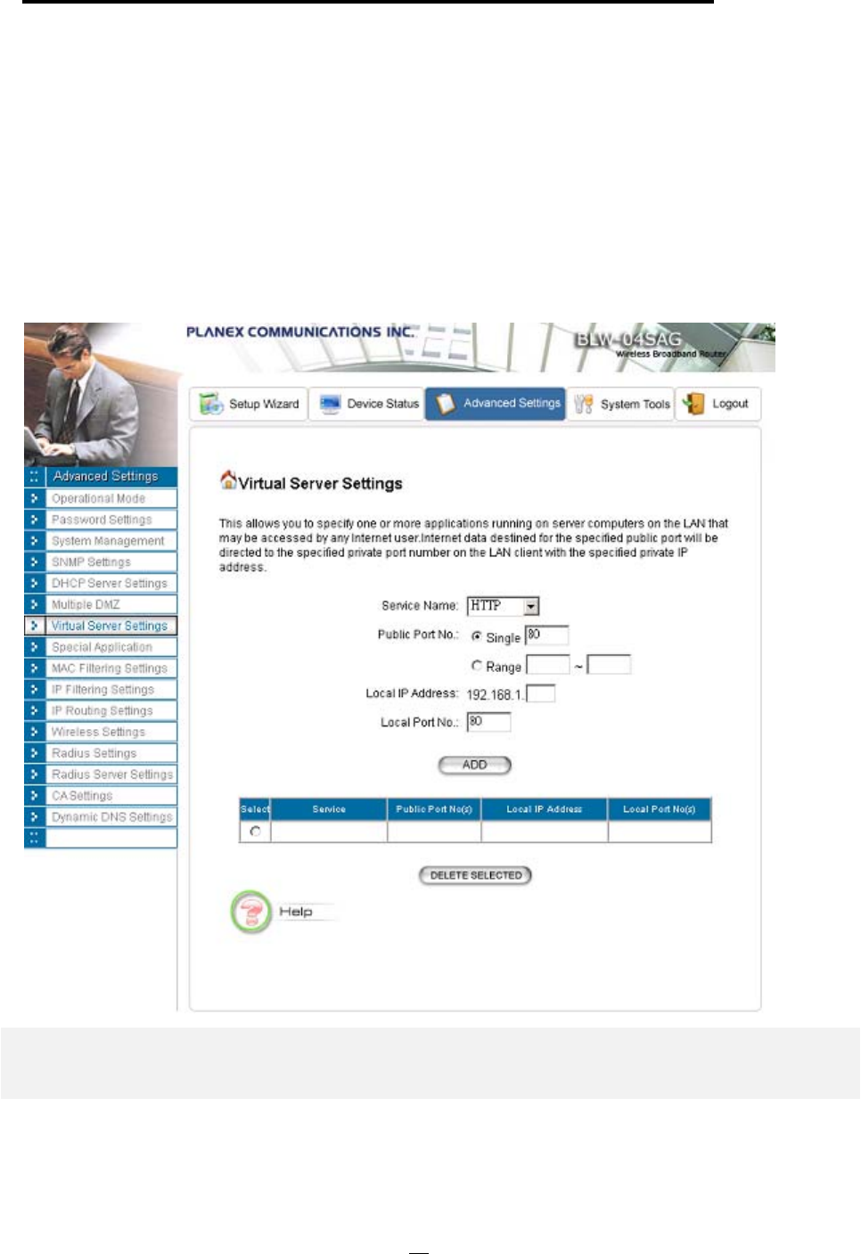
802.11a/g Router User’s Guide
address on the LAN allows access from the Internet by mapping a special port to the HTTP
server. In this case, the HTTP service will be mapped to a special port of the Router.
You can add a virtual server mapping by (1) selecting the service name (such as HTTP, FTP,
TELNET, SMTP, POP3, CUSTOM), (2) enter the public port number to be used (either a
single port number or a range), (3) enter the local IP address of the server on your LAN, (4)
enter its local port number to map to (if is public port number a range, local port number is
not allowed to specify), (5) followed by pressing the ADD button.
You can delete a mapping by selecting the corresponding entry and press the DELETE
SELECTED button.
Note: Virtual Server Setting and IP Filtering may affect with each other.
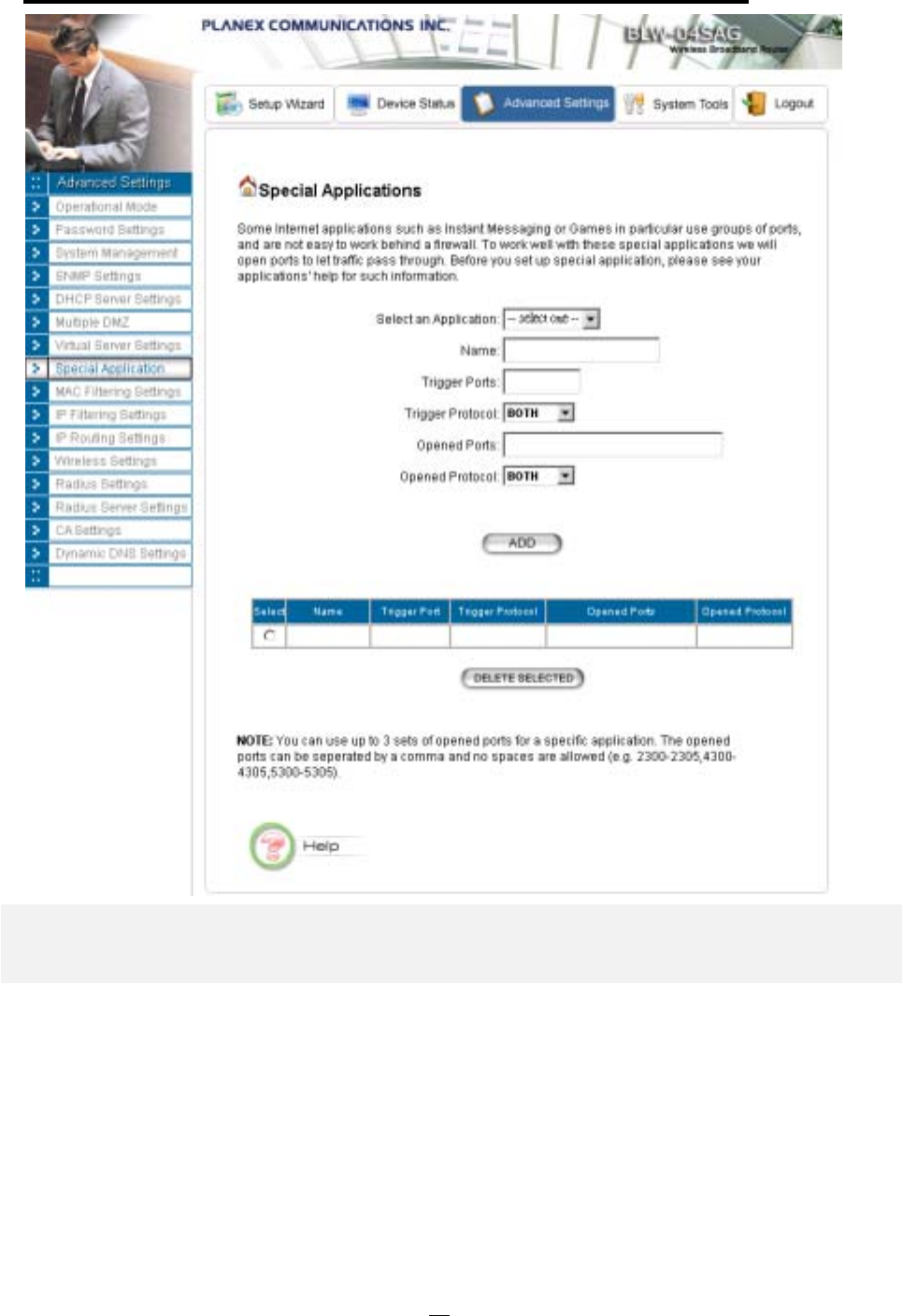
Special Applications
Special applications such as the Microsoft instant messaging or some Internet games are getting
to be increasingly popular. These applications usually work in the following manner:
37

A client can start an Internet game by first registering with a game server on the Internet. Other
clients can, using the corresponding protocol, join the game by checking with the server and
deciding if to join the game. A client can "leave" the game at any time.
If the initiating client is behind your router, you need to add the application by performing the
following configuration:
Select an application: Select an application that you want to add to the supported list. You
should choose "Other" if your application is not explicitly shown in the list.
Name: You can provide a mnemonic name.
Trigger Port: You need to specify, based on instructions provided by your application’s user
manual, the (UDP/TCP) port number in the router that the initiating client uses to start an
Internet game.
Trigger Type: Select UDP, TCP, or both for the trigger port.
Opened ports: You need to specify the port numbers in the router that joining clients can use to
communicate with the initiating client, again based on instructions provided by your application
user manual.
Public Type: Select UDP, TCP, or both for the Opened ports.
After you finish the above, you press the ADD button to add an entry to the table.
You can delete an entry by selecting the corresponding entry and press the DELETE
SELECTED button.
38
802.11a/g Router User’s Guide
MAC Filtering Settings
The 802.11a/g Router allows you to define a list of MAC addresses. One of three mutually
exclusive rules can be selected to forward/filter data packets based on these MAC addresses.
Disable MAC address control list: When this radio button is selected, no MAC address
filtering will be performed.
Enable GRANT address control list: When this radio button is selected, only packets
received from the wireless LAN interface with the configured MAC addresses will be
allowed/forwarded.
39
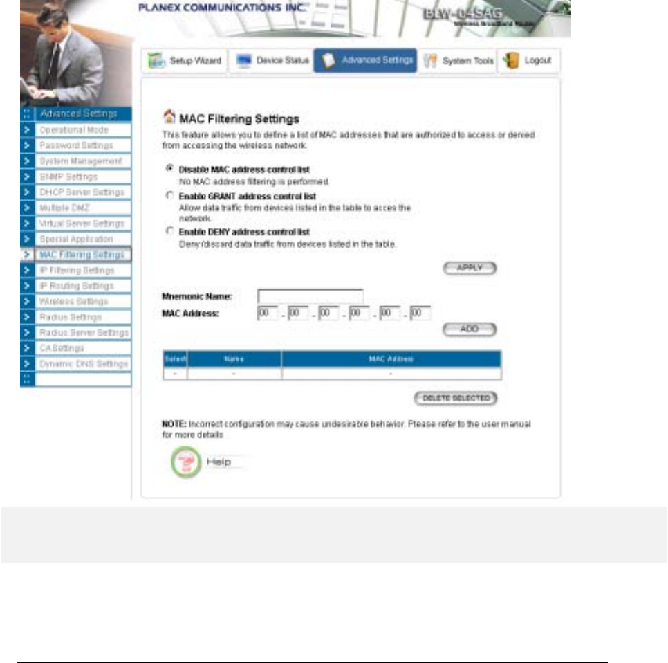
Enable DENY address control list: When this radio button is selected, only packets
received from the wireless LAN interface with the configured MAC addresses will be
denied/filtered.
Once a choice is made, the choice applies to all filtering rules.
To add a filtering rule, configure the following:
Mnemonic Name: the name to identify the filter
MAC Address: the MAC address for grant or deny.
After you finish the above, you press the ADD button to add the entry to the table. There are up
to 32 MAC filtering rules could be configured.
You can delete an entry by selecting the corresponding entry and press the DELETE
SELECTED button.
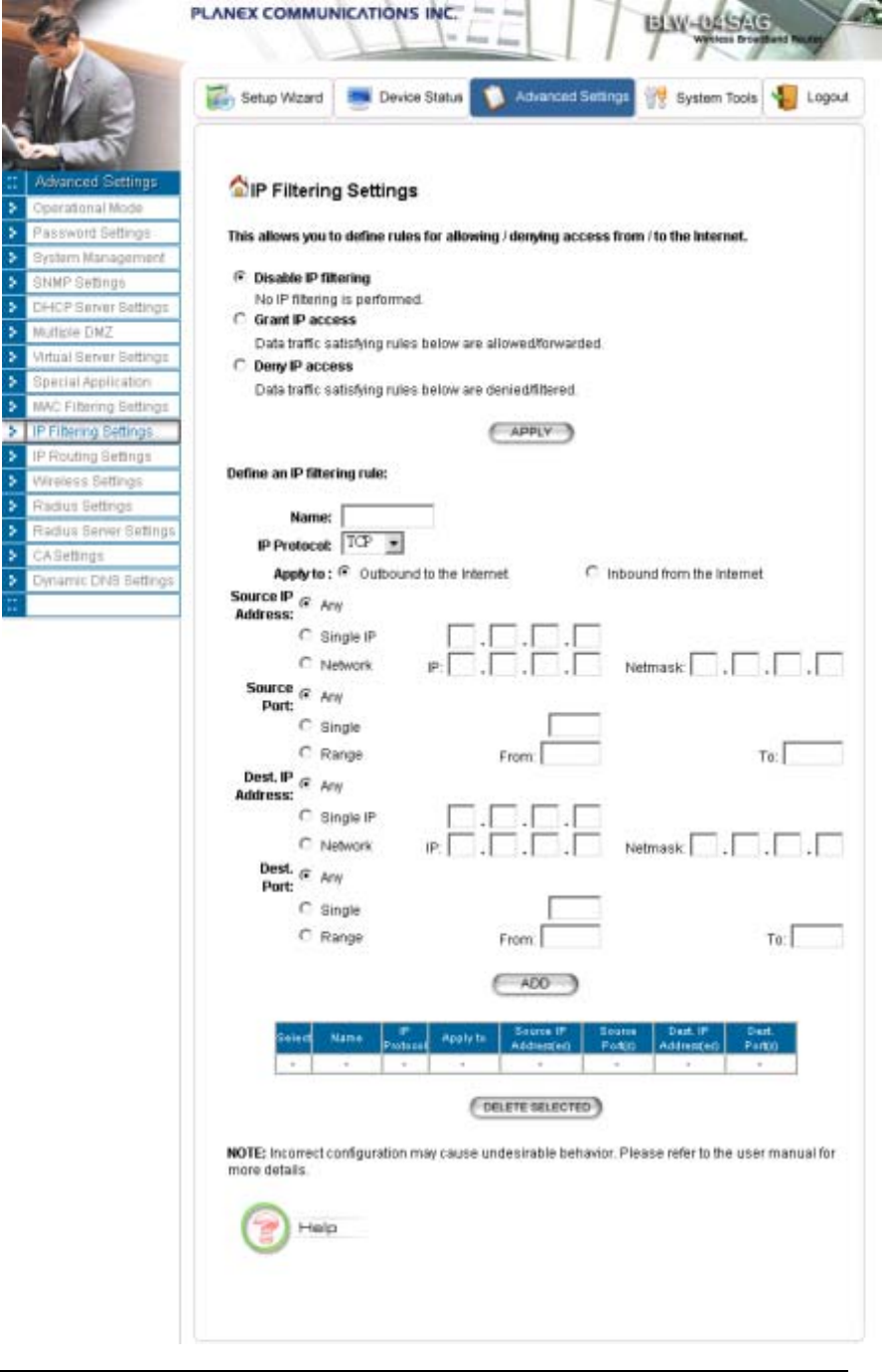
IP Filtering Settings
Three mutually exclusive rules can be defined to forward/filter IP packets based on their IP
address and/or port numbers.
40

802.11a/g Router User’s Guide
Disable IP filtering: If this is selected, the IP filtering feature is disabled. No IP filtering
will be performed.
GRANT IP access: When this is elected, packets received from/transmitted to WAN with
specified (source or destination) IP addresses will be allowed/forwarded.
DENY IP access: Packets received from/transmitted to WAN with the specified IP
addresses will be denied/filtered.
Once a choice is made, the choice applies to all filtering rules.
To define/add an IP filtering rule, enter the following information
• Name: The name of the filter
• IP Protocol: TCP or UDP
• Apply to: You need to select whether the filtering rule should apply to packets outbound
for the Internet or inbound from the Internet.
• Source IP address: you can select Any, Single IP, or a Network (of source IP
addresses).
• Source Port: you can select Any, Single, or a Range of port numbers.
• Destination IP address: Any, Single IP, or a Network (of destination IP addresses).
• Destination Port: you can select Any, Single, or a Range of port numbers.
After you finish the above, you press the ADD button to add the entry to the table. There are up
to 32 IP filtering rules could be configured.
You can delete an entry by selecting the corresponding entry and press the DELETE
SELECTED button.
Please Note that IP filtering is a sophisticated feature that can severely impact your Router
operation. Please be sure that you fully understand it before you use this feature. If you make any
mistakes, it can produce dramatic and potentially undesirable results.
41
42

802.11a/g Router User’s Guide
IP Routing Settings
Dynamic Routing: Enable gateway to exchange the routing table dynamically with other routing
devices. Currently you can select either RIP or OSPF as the routing protocol.
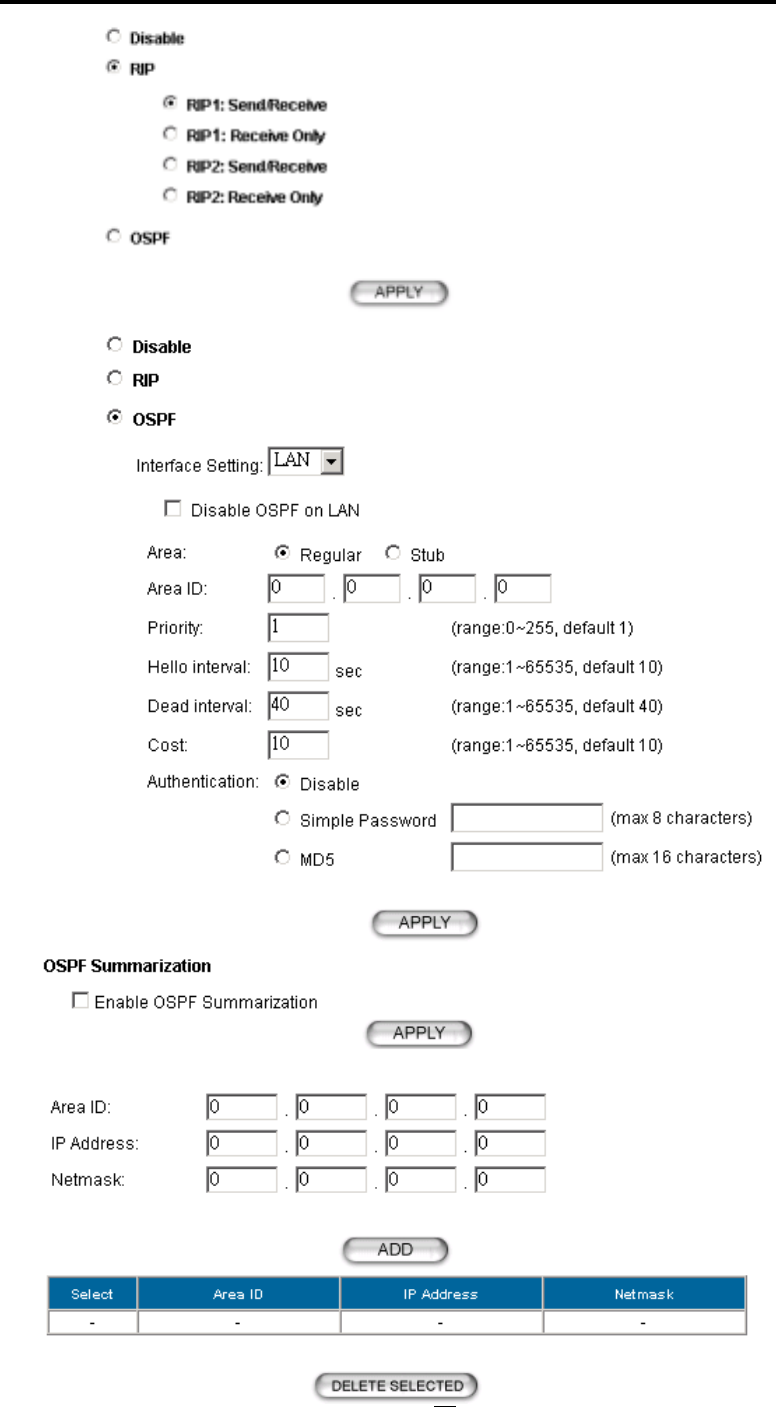
RIP: When RIP is selected, you can choose to run RIP1 or RIP2 with active mode (Send/Receive)
or passive mode (Receive Only). With active mode, the 802.11a/g Router will send out RIP
packets describing its routing database, and it will also update the database according to the
received RIP packets from other routing devices. With passive mode, the 802.11a/g Router will
only update the database according to the RIP packets received, it will not send out any RIP
packets.
OSPF: When OSPF is selected. You can select the interface (LAN and/or WAN) to run OSPF.
For each interface where OSPF is enabled, you have to configure the Area that the interface
belongs to by specifying the Area ID, the Area type (either Regular or Stub), and the priority of
the 802.11a/g Router on the segment the interface belongs to. Also, for the segment that an
OSPF enabled interface, you have to configure the Hello interval and Dead interval on the
segment, the Cost for transmitting a packet on the segment, and the Authentication method
used on the segment. If an authentication method is used, either Simple Password or MD5, a
shared secret has to be configured for the authentication purpose.
OSPF Summarization can be enabled to consolidate multiple routes into one single
advertisement and hence reduce the routing database make routing simpler and faster. When this
function is enabled, it will only be effective when the 802.11a/g Router is an ABR (Area Border
Rouer), that is, at least two OSPF enabled interface are configured with different Area IDs.
For each summarization entry, you have to enter the Area ID such that routes from the Area
falling into the specified subnet (IP address/Netmask) will be summarized into a single route to
the specified subnet and it is the single route instead of the individual route to be injected into
other Areas.
Static Routing: If you have routers on your LAN or WAN, you can configure static routes on the
802.11a/g Router to route network traffic to a specific, predefined destination. The 802.11a/g
Router routes packets based only on the packet's destination not on the source of a packet. Static
routes must be defined if the LAN or WAN are segmented into subnets. For example, a subnet
can be created to isolate a section of a company, such as finance, from traffic on the rest of the
LAN or WAN.
Static Routes are configured when network traffic is directed to a specific destination on the
network whether it is the LAN or WAN. For instance, you can configure the 802.11a/g Router
to route traffic destined to a particular network to a specific router on the LAN or WAN using
the following steps:
1. Enter the IP address of the destination network in the Destination Network field.
2. Enter the subnet in the Subnet Mask field.
3. Enter the IP address of the specific router in the Gateway IP Address field.
4. Select LAN or WAN, where is the specific router is, from the Interface menu.
43
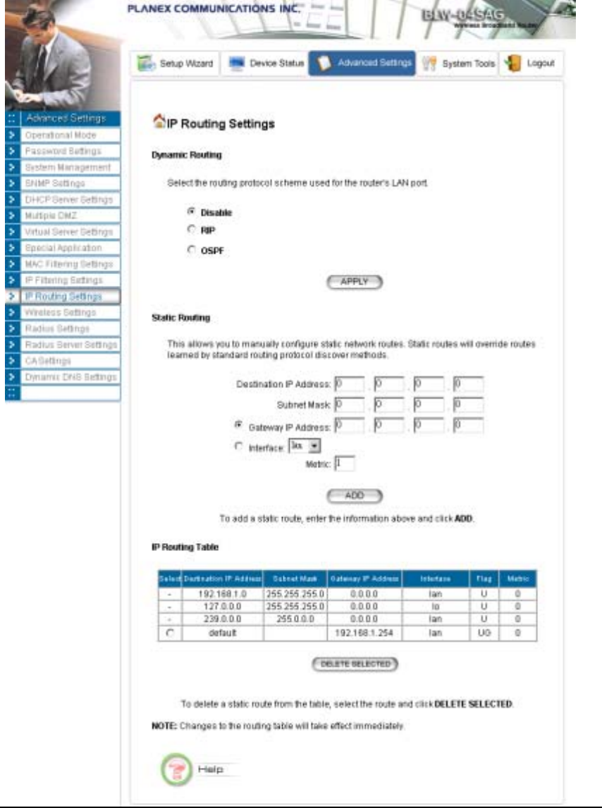
5. Enter the metric (cost) for sending a packet following this route.
6. Click Add.
IP Routing Table: The Routing Table shows a list of destinations that the IP software maintains on
each host and router. The destination network IP address, subnet mask, gateway address, and the
corresponding interface are displayed.
Note! The 802.11a/g Router can support up to 128 static route entries.
44
802.11a/g Router User’s Guide
45
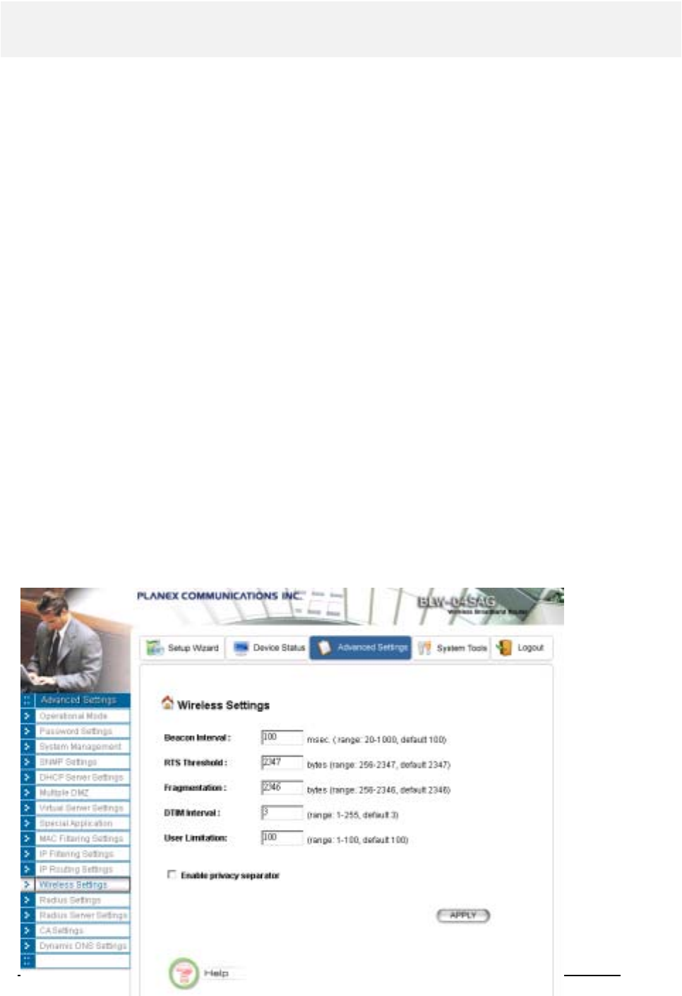
Wireless Settings
You can use this screen to configure various parameters of your 802.11a/g Router.
Beacon Interval: The 802.11a/g Router broadcasts beacon frames regularly to announce its existence.
The beacon Interval specifies how often beacon frames are transmitted - in time unit of milliseconds.
Its default value is 100; a valid value should be between 20 and 1000.
RTS Threshold: RTS/CTS frames are used to gain control of the medium for transmission. Any
unicast (data or control) frames larger than the specified RTS threshold must be transmitted following
the RTS/CTS handshake exchange mechanism. The RTS threshold should have a value between 0 and
2347 bytes, with a default value of 2347. A value of zero activates the RTS/CTS handshake before
every transmission. It is recommended that this value does not deviate from the default too much.
Fragmentation: When the size of a unicast frame exceeds the fragmentation threshold, the frame will
be fragmented before transmission. The threshold should have a value of 256-2346 bytes, with a
default value of 2346. If you experience a high packet error rate, you should slightly decrease the
Fragmentation Threshold.
DTIM Interval: The 802.11a/g Router buffers packets for stations that operate in the power-saving
mode. A Delivery Traffic Indication Message (DTIM) contains information on which power-
conserving stations have packets waiting to be received. The DTIM interval specifies how often
beacon frames should contain DTIMs. It should have a value between 1 and 255, with a default value
of 3.
User Limitation: You can limit the number of stations that can get associated with the 802.11 a/g
Router; the purpose is to assure the WLAN service quality provided.
Enable privacy separator: To increase the security and prevent any two WLAN connected device
from accessing each other, you can check this option.
46

802.11a/g Router User’s Guide
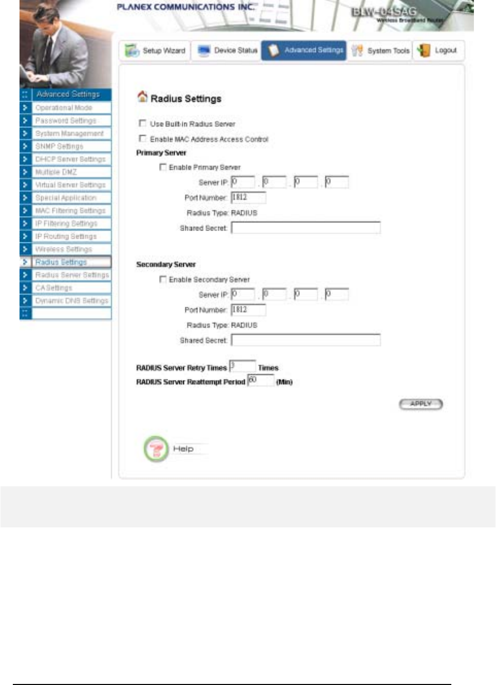
RADIUS Settings
RADIUS (Remote Access Dial-In User Service) servers provide centralized authentication services to
wireless clients. For the WLAN security policy 802.1x and WPA, a RADIUS server is required for the
authentication purpose. Users can use the built-in RADIUS server and/or configure up to two
RADIUS servers can be used, one acting as a primary, and the other as a backup.
Use Built-in Radius Server: The built-in RADIUS server can be used for the 802.1x and WPA
security policies. When this option is checked, the primary/secondary RADIUS server would be used
only if the built-in RADIUS server is not enabled. The built-in RADIUS server can be enabled at the
“Radius Server Settings" page. However, when you check the “Enable Built-in Certificate Authority”
option at the “Radius Server Settings" page, this option “Use Built-in Radius Server” will be checked
automatically.
Enable MAC Address Access Control: MAC address filtering requires a MAC address filter table to
be created in either the 802.11a/g Router and/or the RADIUS server. During the 802.11
authentication phase, the MAC address filter table is searched for a match against the wireless client’s
MAC address to determine whether the station is to be allowed or denied to access the network. To
leverage a RADIUS server for MAC address access control, check the box here.
To use this feature, you have to configure the MAC addresses of authorized WLAN clients as the user
name and password in the RADIUS server you use, and the RADIUS server should support PAP
authentication.
Enable Primary Server: To configure the primary server, check the “Enable Primary Server” box,
and configure the following parameters:
Server IP: The IP address of the RADIUS server
Port Number: The port number your RADIUS server uses for authentication. The default setting is
1812.
Shared Secret: This is used by your RADIUS server in the Shared Secret field in RADIUS protocol
messages. The shared secret configured in the 802.11a/g Router must match the shared secret
configured in the RADIUS server. The shared secret can contain up to 64 alphanumeric characters.
Enable Secondary Server: To configure the secondary server, check the “Enable Secondary Server”
box, and configure the same parameters as for the primary server.
RADIUS Server Retry Times: The number of times the 802.11a/g Router should attempt to contact
a RADIUS server before giving up and try the next RADIUS server. The contact sequence is Built-in
server (if used) Primary server (if enabled) Secondary server (if enabled).
RADIUS Server Reattempt Period: After failed to contact the first RADIUS server (the built-in
server, or the Primary server if the built-in server is not used), the 802.11a/g Router will re-attempt to
contact the first server every this mount of minutes even if the server being used is still working.
47
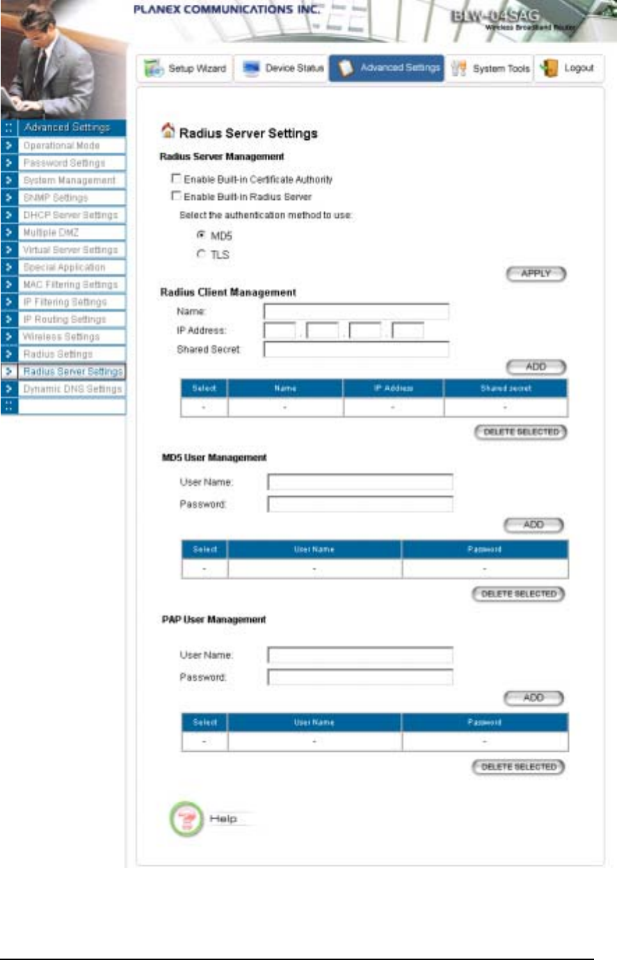
Radius Server Settings
The 802.11a/g Router has a built-in RADIUS server so users don’t have to setup a separate RADIUS
for the use of WLAN 802.1x and WPA security policies and MAC address access control. To use the
built-in RADIUS server, users have to select the “Enable Built-in Radius Server” check box. The
built-in RADIUS server currently provides two types of authentication methods for EAP
authentication: MD5 and TLS (i.e. EAP-MD5 or EAP-TLS). The way to configure the setting for the
TLS type depends on whether the built-in CA (certificate authority) is enabled. The built-in CA is
enabled by selecting the “Enable Built-in Certificate Authority” option. If the built-in CA is enabled,
the built-in RADIUS server will use the built-in CA to issue its own certificate and requires all the user
certificates issued by the built-in CA. So when the built-in CA is enabled, users do not have to
48

802.11a/g Router User’s Guide
configure anything for the TLS type. If the built-in CA is not enabled, users have to enter the built-in
RADIUS server’s certificate issued by an external CA (by specifying “Certificate Path”), the password
to use the certificate (by specifying “Password”), and the certificate of the CA issuing all the user
certificates (by specifying “Root CA Certificate Path”). The expected format for the built-in
RADIUS server’s certificate is PEM (extension file name: .pem) and the expected format for the CA’s
certificate is DER encoded binary X.509 (extension file name: .CER). Click the APPLY button to
make the settings effective. Once the built-in RADIUS server is enabled, the “Use Built-in Radius
Server” option at the “Radius Settings” page is automatically checked.
The built-in RADIUS server does not require a user listed in its user database when TLS type is being
used. So when the TLS type is selected, users do not have to add any user information into the built-in
RADIUS server’s database.
When the MD5 type is selected, users have to add the User Name and Password for each user into
the built-in RADIUS server’s database. The database management is in the MD5 User Management
section. A MD5 user can be removed from the database by selecting the user in the table and clicking
the DELETE SELECTED button.
For each RADIUS client that will use the built-in RADIUS server, users have to add a client entry in
the “Radius Client Management” section.
Name: a mnemonic name for the RADIUS client.
IP Address: the IP address of the RADIUS client.
Shared Secret: the shared secret pass phrase used to authenticate the RADIUS client.
When the built-in RADIUS server is enabled, the PAP authentication function is always enabled. The
PAP authentication function is used for WLAN MAC address control (the "Enable MAC Address
Access Control" option at the "Radius Settings" page); in this case, the MAC address of an authorized
WLAN client is used as both user name and password. A PAP user can be added in the PAP User
Management section with the User Name and Password entered. A PAP user can be removed
from the database by selecting the user in the table and clicking the DELETE SELECTED button.
49
50

802.11a/g Router User’s Guide
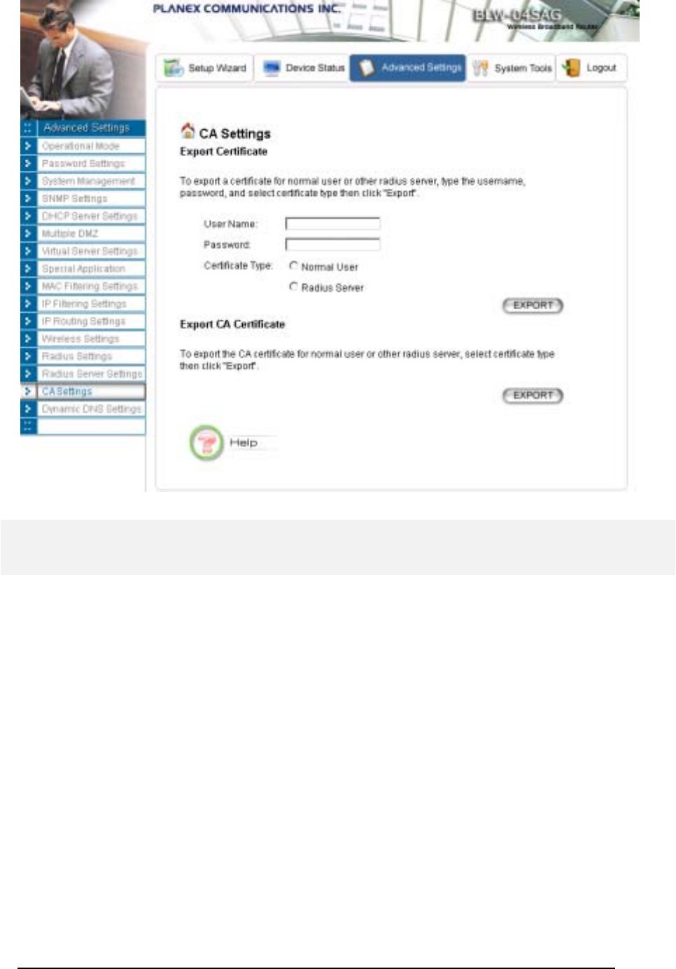
CA Settings
If you enable the “Built-in Certificate Authority” function at the “Radius Server Settings” page, you can
see the “CA Settings” in the left side menu on “Advanced Settings” pages.
The CA (Certification Authority) allows you to request certificates for WLAN clients/stations and for
RADIUS servers. A certificate is required for a WLAN client and/or the RADIUS server when the
WLAN security policy is 802.1x or WPA with the EAP type as TLS, PEAP, and TTL…. In the case
where the RADIUS server will authenticate a WLAN client, the WLAN client needs to have a
certificate for itself, and the RADIUS server needs to have the certificate of the CA issuing the client’s
certificate. In the case where a WLAN client will authenticate the RADIUS server, the RADIUS server
needs to have a certificate for itself, and the WLAN client needs to have the certificate of the CA
issuing the RADIUS server’s certificate.
To acquire a certificate for a WLAN client or a RADIUS server, enter the name and password for the
client or server, and select the corresponding certificate type (“Normal User” for a WLAN client and
“Radius Server” for a RADIUS server). Then click the EXPORT button and specify the file path to
save the certificate on your PC. The User Name is used to identify the holder of the certificate to be
issued, and the holder need the Password in order to use the issued certificate (so people not knowing
the password cannot use the certificate). Currently the supported format for a “Normal User”
certificate is PKCS #12 (extension file name: .p12), and the supported format for a “Radius Server”
certificate is PEM (extension file name: .pem).
To get the CA’s certificate, just click the EXPORT button and specify the file path to save the certificate
on your PC. The format for the CA’s certificate is DER encoded binary X.509 (extension file
name: .CER).
51
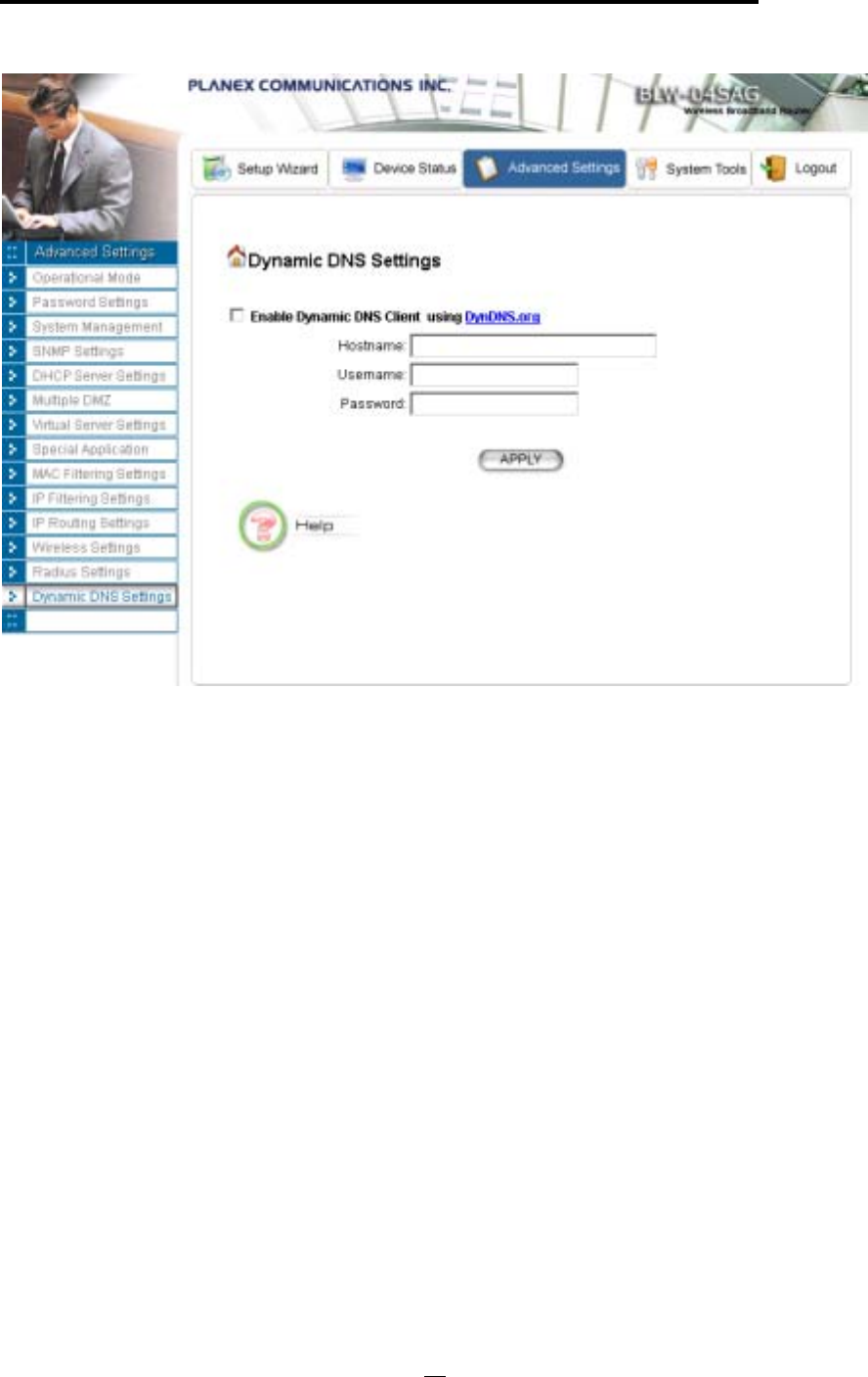
Dynamic DNS Settings
Some people advertise the IP addresses of their routers so that Internet users can access these
routers (which is actually to access virtual servers behind these routers) using these IP addresses.
However, for those routers that are assigned dynamic IP addresses from the ISP, this approach
requires additional work (since the addresses assigned are not always the same).
The 802.11a/g Router implements the dynamic DNS feature so that each time it is booted, it will
re-register its domain-name-to-IP-address mapping with the dynamic DNS server you use
(currently only DynDNS.org is supported), the service provider that provides domain name to IP
address mapping. This is so that you can advertise your router by providing your domain name,
while Internet users can access the router using the domain name, not the router’s IP address.
To activate this feature, you need to check the “Enable Dynamic DNS Client using
DynDNS.org” box first, and then configure the following parameters:
Hostname: the hostname (domain name) registered with DynDNS.org by you.
Username: the username required to log in to the domain name server maintained by
DynDNS.org.
52
802.11a/g Router User’s Guide
Password: the password required to log in to the domain name server maintained by DynDNS.org.
53
C
h
apte
r
5
Managing your 802.11a/g Router
This Chapter covers other management aspects of your 802.11a/g Router:
How to view the device status
How to view the system log
How to upgrade your 802.11a/g Router firmware
How to save or restore configuration changes
How to reboot your 802.11a/g Router
What if you forgot the password
How to View the device Status
You can monitor the system status and get general device information from the Device Information
screen:
54
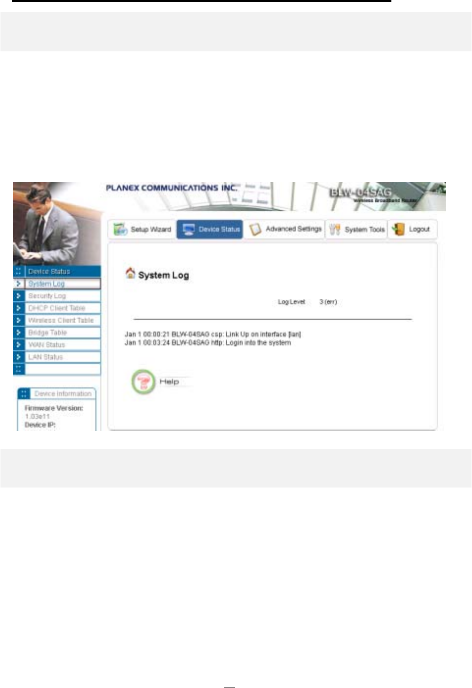
802.11a/g Router User’s Guide
How to View the System Log
The 802.11a/g Router maintains a system log that you can use to track events that have occurred in the
system. Such event messages can sometimes be helpful in determining the cause of a problem that you
may have encountered.
You can select System Log on the left to view log events recorded in the system. The System Log
entries are shown in the main screen along with the log level, the severity level of messages that are
being displayed (a low number such as 2 means critical), and the uptime, the amount of time since the
802.11a/g Router was last reset. The maximum number of entries is 128. If there are more than 128
entries, older entries will be deleted.
Security Log
The 802.11 a/g Router maintains another log table for security logs. For each filter rule configured, the
802.11 a/g Router will monitor the traffic matching the rule. Once the rule’s hitting rate exceeds a
certain degree (twice per 10 seconds, that is, more than one packet matching the rule in 10 seconds), a
security log is generated and stored in the security log table. A security log entry contains a description
regarding the event and a time stamp when the event happened. You can see the current logged
security events from this page. Those log entries are not saved into flash, so all log messages are
removed after the system reboot. The maximum number of entries is 128. If there are more than 128
entries, older entries will be deleted.
55
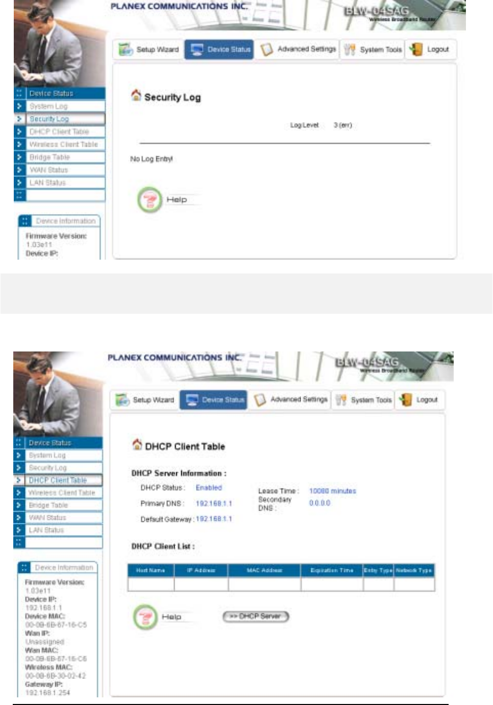
DHCP Client Table
The DHCP client table lists current DHCP clients connected with its host name, IP address, MAC
address, expiration time, entry type, and network type.
56
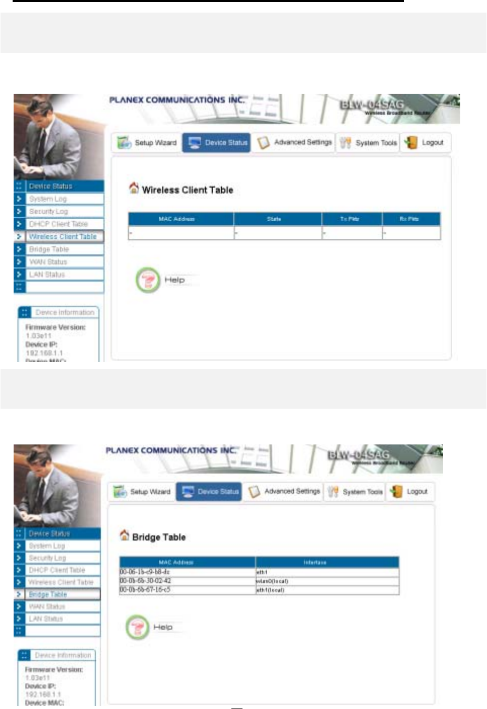
802.11a/g Router User’s Guide
Wireless Client Table
The wireless client table lists the current wireless clients with its MAC address, state, number of
transmitted packets, and number of received packets.
Bridge Table
The bridge table shows all MAC entries learned from the wired LAN interface, wireless clients, and
WDS peers.
57
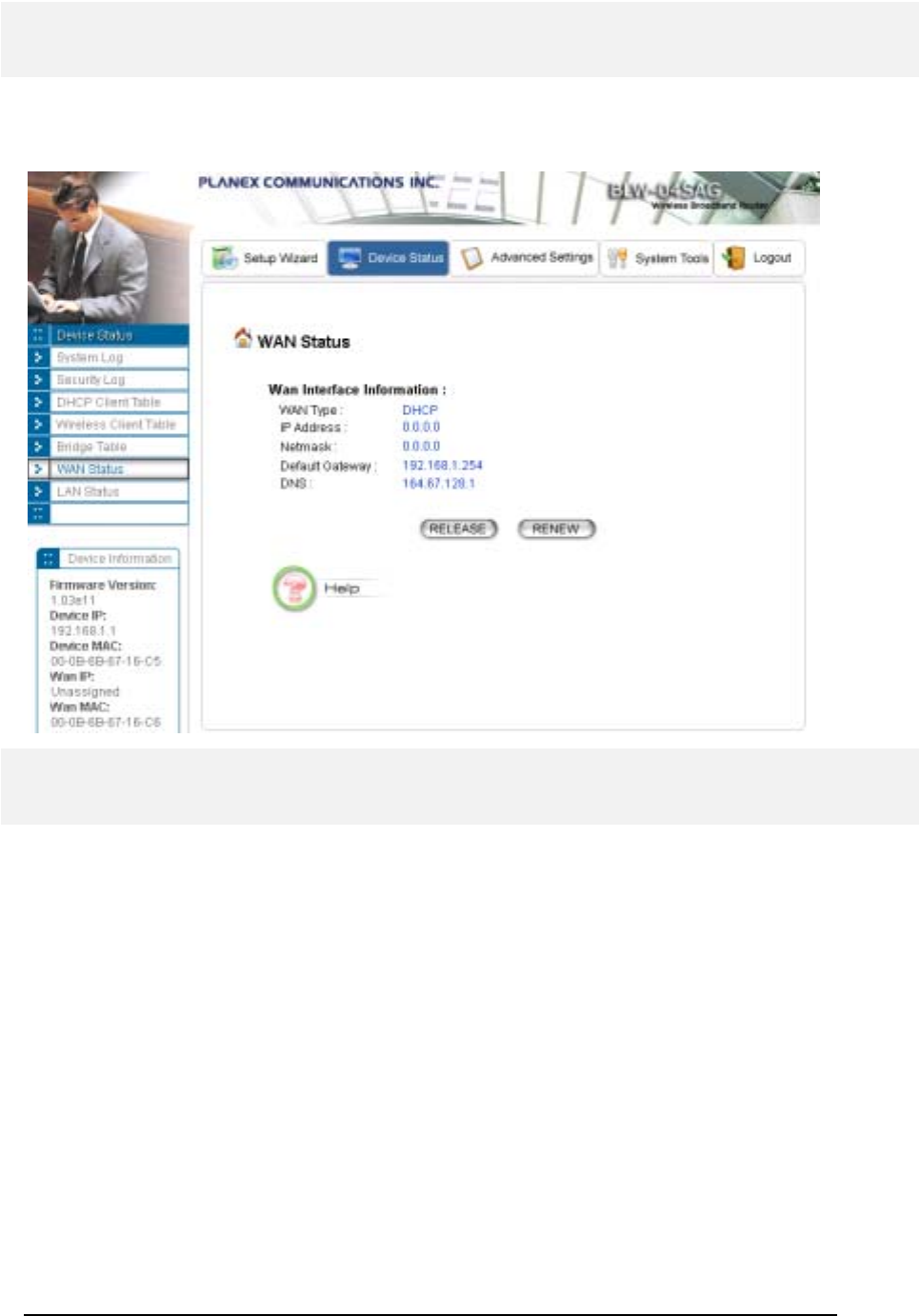
WAN Status
The WAN Status page shows the WAN connection status, including the public IP address assigned
from the ISP and the DNS address. For the DCHP client connection, you can release and renew the
WAN IP address; for the PPPoE connection, you can disconnect and connect the link.
LAN Status
This page displays the status of the 4 LAN ports. For each port, you can see the link status
(Up/Down), duplex mode (Full/Half), and speed (10M/100M bps).
58
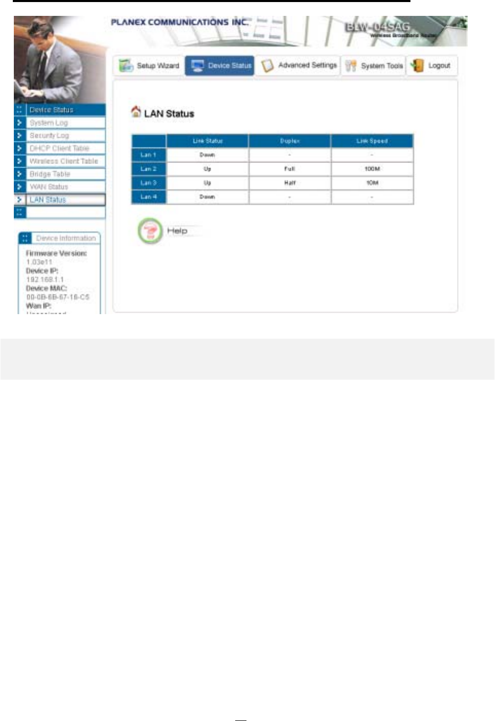
802.11a/g Router User’s Guide
Upgrading Firmware
You can upgrade your 802.11a/g Router’s firmware (the software that controls your 802.11a/g
Router’s operation). Normally, this is done when a new version of firmware offers new features that
you want, or solves problems you have encountered using the current version. System upgrade can be
performed through the System Upgrade option as follows:
Step 1 Select System Tools, then Firmware Upgrade from the menu and the following screen
displays:
59
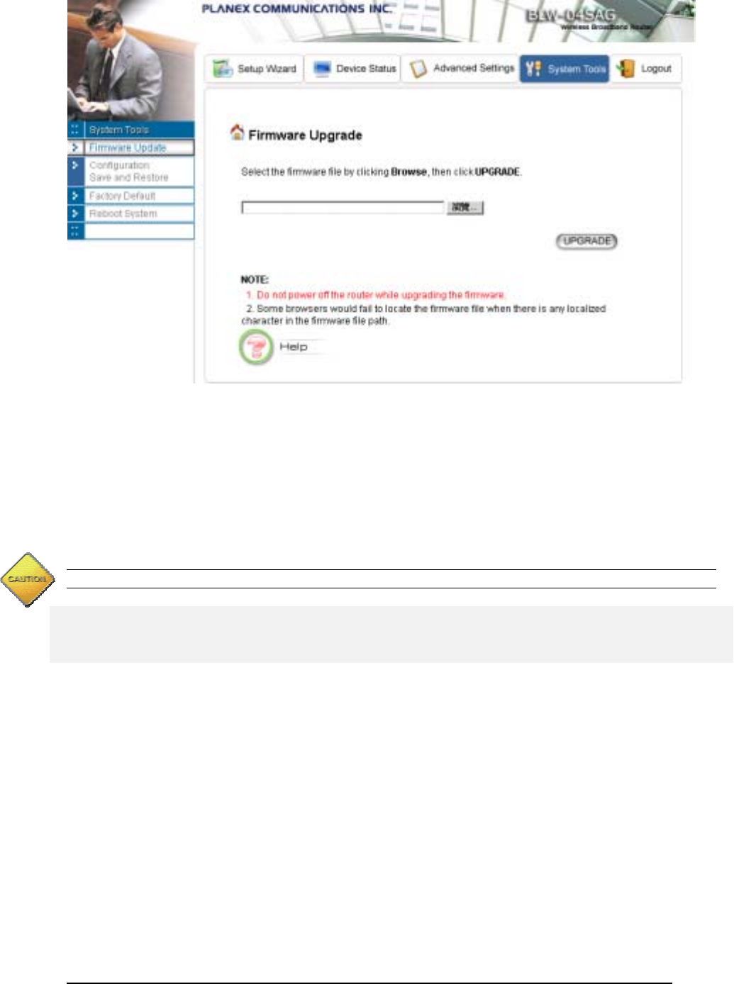
Step 2: To update the 802.11a/g Router firmware, first download the firmware from the distributor’s
web site to your local disk. Then from the above screen enter the path and filename of the firmware
(or click Browse to select the path and filename of the firmware). Next, Click the Upgrade button.
The new firmware will begin loading to your 802.11a/g Router. After a message appears telling you
that the operation is complete, you need to reset the system to have the new firmware take effect.
Note: It is recommended that you do not upgrade your 802.11a/g Router if you are happy with its operation.
How to Save or Restore Configuration Changes
You can save system configuration settings to a file, and later download it back to the 802.11a/g
Router system by following the steps below.
Step 1 Select Configuration Save and Restore from the System Tools menu and the following
screen displays:
60
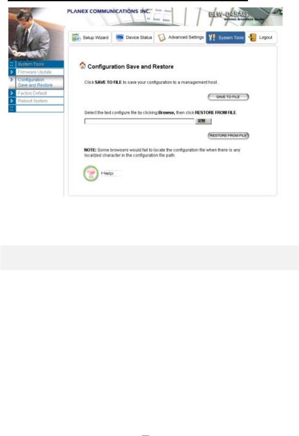
802.11a/g Router User’s Guide
Step 2 Click SAVE TO FILE and then select a local file to save to, or select a local file to upload and
then click RESTORE FROM FILE.
How to Restore the System Settings to the Factory Defaults
You can restore the system settings to the factory defaults.
Step 1 Select Factory Default from the System Tools menu and the following screen displays:
61
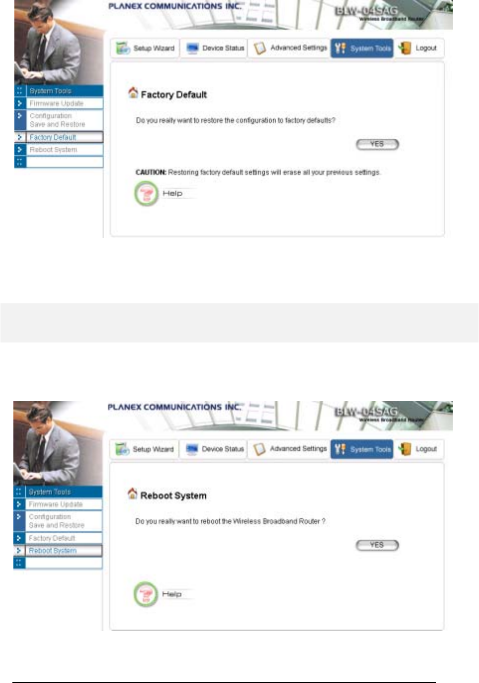
Step 2 Click YES to restore the system configurations to the factory defaults, and the system will
reboot automatically.
How to Reboot your 802.11a/g Router
You can reset your 802.11a/g Router from the Brower. To reset it:
Step 1 Select Reboot System from the System Tools menu, the following screen shows:
Step 2 Click YES to reset the 802.11a/g Router.
62

802.11a/g Router User’s Guide
Note: Resetting the 802.11a/g Router disconnects any active clients, and therefore will disrupt any current
data traffic.
What if you Forgot the Password?
If you forgot the password, the only way to recover is to clear the device configuration and return the
unit to its original state as shipped from the factory. You can do this by pressing the hardware
“restore” button on the device for “2 seconds”. Please note that this will require you to re-enter all of
your configuration data.
63

C
h
apte
r
6
Command Line Interface
This chapter describes the Command Line Interface (CLI) for the 802.11 a/g Router. The CLI is
accessible through a Telnet session.
General guidelines
When the 802.11 a/g Router is powered up, the user can use a standard telnet application from a PC
connected to the network to perform configuration and management functions. This is done by typing
the telnet command, “telnet <the 802.11 a/g Router’s ip>” (the default is 192.168.1.1) and pressing a
return key, the user will see a system sign-on message followed by a password prompt as follows.
Router Manager Console <rev_no>
please enter your password:
A default password “password” has been pre-configured with the system. The user should use it to log
into the system until the password is explicitly changed using the
change password
command. Note
that the entered password is case-sensitive. This password may also be changed using the browser-
based GUI configuration utility.
The password entered will be echoed back as asterisks (*). After the Carriage Return is entered, if the
password string is validated, the command prompt
Command>
will be displayed, and the user can
then issue other commands. Otherwise, the password prompt will be redisplayed.
Most commands are single-line commands, and commands are not context sensitive: each command is
independent of other commands before or after it.
The command syntax is straightforward.
The following briefly summarizes the guideline for the interface.
At any time, the user can type a “?” (preceded by a space) to request context-sensitive help on
what the user can enter next.
At any time, the user can type control-p (^p, by pressing both the Ctrl key and the p key at the
same time) to repeat the previous command, or control n to return to the following (next)
command. At startup, typing ^p or ^n will not cause anything to happen - since previous
commands do not yet exist. In normal operation, typing ^p will cause the previous command to
show, and the cursor will sit at the end of the command. At this point, the user can either type a
carriage return to accept the command, or type backspaces to edit the command from the end.
Up to 15 previously entered commands can be invoked through ^p’s and ^n’s.
64

802.11a/g Router User’s Guide
If a keyword is expected when the user types “ ?”, all valid keywords will be displayed. The
command typed in so far will then be displayed again along with the cursor sitting at the end,
waiting for the user to continue.
If the user types in part of the keyword but does not type in the entire word, the user can then
enter a tab or space for the system to automatically complete the keyword if the characters typed
in so far can uniquely identify the keyword. If the characters typed in so far do not uniquely
identify a keyword, a list of possible keywords will be displayed.
If the user is not sure what to type next, he or she can type "?” to display the possible keywords
that match the current CLI command input.
If an interactive mode is entered, the system will prompt for each required parameter, such as:
…
Command> add radius server primary
enter server IP (Unspecified): 192.168.1.10
enter port number (1812, 1-65535): 1812
enter shared secret:
…
The first prompt means current IP setting is not specified yet, and there is no default for that.
The second prompt means a number between 1 and 65535 is expected, with 1812 being the
default.
During the first time a particular parameter is configured, typing a carriage return will cause the
default value to be selected. Otherwise, typing a carriage return means no change to the current
value.
Express Mode vs. Advanced Mode of operation
The Command Line Interface operates in one of two modes:
Express
Mode
or
Advanced
Mode
. In Express Mode, not all parameters are displayed. Default values are set for those
parameters not displayed in multi-line commands. In Advanced Mode, users have the option to
modify all possible values appropriate to each operation.
The user can toggle between Express Mode and Advanced Mode by typing ^E (Control-E) at any
time. Normally, the system prompt will be changed by appending “>>” to the configured prompt
when in Advanced Mode.
Conventions
The following notations will be used:
lan means the LAN port;
wlan means the Wireless port;
65

<> specifies the arguments of the command, <1-4> means a number between 1 to 4;
[ ] indicates an optional parameter
| is used to separate alternative choices of parameters or keywords;
{} encloses all alternative keywords;
MacAddr, or XX-XX-XX-XX-XX-XX means any MAC address in hexadecimal format,
where each XX can be 00, 01, ... 99, 0A, 0B, 0C, 0D, 0E, 0F, 10, 11,… FF;
ipAddr, netmask, or xxx.xxx.xxx.xxx means any ip address or network mask, where xxx is a
decimal integer between 0 and 255;
The term string means a string of characters up to the specified length, which may be enclosed
in double quotes (“) (required if the string contains embedded blanks);
Names representing filters and MAC addresses could be up to 30 characters in length;
password and SNMP community read/write strings are up to 15 characters in length. When
the password and SNMP community write string are entered, they are echoed back as a string
of “*”s for protection, while other parameters, such as WEP keys, are echoed back the way
they are typed (in clear text).
List of Commands
From a functional point of view, CLI commands will be grouped into the following categories:
(1) System
(2) IP
(3) Filtering
(4) DHCP Server
(5) SNMP
(6) Diagnostics
(7) Security
The command format will be described in the following sections.
(1) System Commands
clear config
Description: Reset the system configuration to the factory default.
disable ntp client
Description: Disable the NTP (Network Time Protocol) client function.
66

802.11a/g Router User’s Guide
disable upnp
Description: Disable the UPnP function.
enable ntp client
Description: Enable the NTP (Network Time Protocol) client function.
enable upnp
Description: Enable the UPnP function.
help
Description: Show help descriptions on CLI.
logout
Description: Logout the current CLI management session.
ping <IP address>
Description: Show help descriptions on CLI.
reset system
Description: Reboot the system. Any configuration not saved (e.g. by “save config”) will be lost.
save config
Description: Save the current configuration onto the flash, so the configuration will be kept after the
system is rebooted.
set http port <port number, 1-65535>
Description: Set the HTTP server port (for device management) to the one specified.
set http timeout <timeout value in minutes, 1-60>
Description: Set the timeout value for the HTTP management session.
set ntp client
Description: Configure the NTP (Network Time Protocol) client related settings. This is a multi-line
command, and you need to enter the time zone of the device, the NTP server name or IP address,
NTP request interval, and enable the NTP client function or not.
set prompt <string up to 15 characters>
Description: Set the command line prompt.
67

set system contact <string up to 60 characters>
Description: Configure a string describing the system contact information. This is the value of the
SNMP system contact MIB.
set system ip
Description: Set the IP address for the device LAN interface.
set system location <string up to 60 characters>
Description: Configure a string describing the system location information. This is the value of the
SNMP system location MIB.
set system name <string up to 30 characters>
Description: Configuring a string for the system name. This is also the value of the SNMP system
name MIB.
set telnet port <port number, 1-65535>
Description: Set the TELNET server port (for device management) to the one specified.
set telnet timeout <timeout value in minutes, 1-60>
Description: Set the timeout value for a TELNET management session.
show arp table
Description: Display the ARP table of the system.
show http
Description: Display the current configurations of the HTTP management function.
show ntp client
Description: Display the current configurations of the NTP client function.
show system
Description: Display the current basic system configurations.
show system ip
Description: Display the current device IP settings of the system.
show telnet
68

802.11a/g Router User’s Guide
Description: Display the current configurations of the TELNET management function.
show upnp
Description: Display the current configurations of the UPnP function.
(2) IP Commands
add ip default route <gateway address>
Description: Add an IP default route to go to the specified gateway IP address.
add ip route <destination IP> <destination netmask> <gateway
address/interface name> <hop counts>
Description: add an IP route to the destination network specified through the specified gateway or
interface with the specified cost. A <destination netmask> is in the format of xxx.xxx.xxx.xxx, for
example, 255.255.254.0.
delete ip default route
Description: Delete the IP default route.
delete ip route <destination IP> <destination netmask>
Description: Delete the IP to the specified network.
disable rip <interface name, string up to 15 characters>
Description: Disable the RIP function on the specified interface.
enable {rip1 | rip2} {active | passive} [<interface name, string up to 15 characters>]
Description: Enable and set RIP mode as RIP1/RIP2 active/passive on the specified interface. If no
interface is specified, this setting applied to all interfaces.
show ip routing table
Description: Display the system IP routing table.
show rip [<interface name, string up to 15 characters>]
Description: Display the current RIP settings on the specified interface. If no interface is specified, this
command displays the current RIP settings on all the interfaces.
(3) Filtering Commands
add mac filter <string up to 30 characters> <MAC address, XX-XX-XX-XX-XX-XX>
Description: Add a MAC filter with the specified name (a mnemonic name) and MAC address.
delete mac filter <string up to 30 characters>
69

Description: Delete the MAC filter with the specified name.
set mac filter mode <MAC filter mode, disabled/grant/deny>
Description: Set the MAC filter mode.
show mac filter [<string up to 30 characters>]
Description: Display the MAC filter entry with the specified name. If no name is specified, this
command display all currently configured MAC filter entries.
show mac filter mode
Description: Display the currently configured MAC filter mode.
(4) DHCP Server Commands
add dhcp static <IP address> <MAC address, XX-XX-XX-XX-XX-XX>
Description: Add a static DHCP client entry with the specified IP address and MAC address.
delete dhcp static <IP address>
Description: Delete the static DHCP client entry with the specified IP address.
disable dhcp server
Description: Disable the DHCP server function.
enable dhcp server
Description: Enable the DHCP server function.
set dhcp server
Description: Configure the DHCP server related settings. This is a multi-line command, and you have
to enter the IP address pool range, gateway IP address, and lease period.
show dhcp client table
Description: Display the current dynamic DHCP clients.
show dhcp server
Description: Display the current DHCP server settings.
show dhcp static
Description: Display the current static DHCP clients.
70

802.11a/g Router User’s Guide
(5) SNMP Commands
disable snmp
Description: Disable the SNMP function.
enable snmp
Description: Enable the SNMP function.
set community string {read | write} <string up to 15 characters>
Description: Configure the SNMP READ/WRITE community string.
show community string read
Description: Display the SNMP READ community string.
show snmp
Description: Display the current SNMP settings.
show snmp statistics
Description: Display the current SNMP statistics.
show trap manager [<string up to 30 characters>]
Description: Display the settings of the specified SNMP trap manager. If no trap manager is specified,
this command displays the settings of all trap managers.
(6) Diagnostics Commands
disable log <facility>
Description: Disable the log function on the specified facility.
disable syslogd
Description: Disable the remote log function.
disable trace <facility>
Description: Disable the trace function on the specified facility.
enable log <facility> [<log level, 1-7>]
Description: Enable the log function with the specified log level on the specified facility. If no log level
is specified, the previously configured log level is used.
enable syslogd
71

Description: Enable the remote log function.
enable trace <facility> [<log level, 1-7>]
Description: Enable the trace function with the specified log level on the specified facility. If no log
level is specified, the previously configured log level is used.
set log level <log level, 1-7>
Description: Set the log level.
set syslogd <IP address>
Description: Configure the IP address of the remote syslog daemon. This is used for the remote
syslog function.
show log level
Description: Display the current log level.
show log table [<facility>]
Description: Display the current logged events of the specified facility. If no facility is specified, this
command displays all logged events.
show syslogd
Description: Display the current configuration of the remote log function.
(7) Security Commands
add radius server {primary | secondary}
Description: Configure the primary/secondary RADIUS server settings. This is a multi-line command,
and you have to enter the IP address and port number of the server, shared secret, and enable/disable.
change password
Description: Change the password for management, including HTTP and TELNET.
disable radius mac authentication
Description: Disable the use of external RADIUS servers for MAC address access control.
disable radius server {primary | secondary}
Description: Disable the use of the primary/secondary RADIUS server.
enable radius mac authentication
Description: Enable the use of external RADIUS servers for MAC address access control.
72

802.11a/g Router User’s Guide
enable radius server {primary | secondary}
Description: Enable the use of the primary/secondary RADIUS server.
set radius server reattempt <reattempt interval in minutes, 5-60>
Description: Configure the reattempt time for the system to contact the primary RADIUS server after
the primary RADIUS server was down.
set radius server retry <retry interval in times, 1-5>
Description: Configure the number of retries after which the system may think the RADIUS server is
down.
show radius server [{primary | secondary}]
Description: Display the configuration of the specified RADIUS server. If no server is specified, this
command displays the configurations of all RADIUS servers.
73

Text Configuration
The text configuration provides another way for users to configure the 802.11 a/g Router. Users can
save the system current configuration onto a file on PC, edit the configuration file, and then restore the
system configuration with the configuration file. For details regarding the save and restore
configuration operations, please read the HOW TO SAVE OR RESTORE CONFIGURATION CHANGES
section in the MANAGING YOUR 802.11A/G ROUTER chapter. This chapter describes the syntax
and semantics of a text configuration file.
General guidelines
The format of a text configuration file is like the Microsoft Window® INI (extension file
name: .ini) file format. The basic file structure can be divided into the following parts:
1. Sections
A section name is enclosed in square brackets, alone on a line. Section names are allowed to
contain any character but square brackets or linefeeds. For example: “[sectionName]”.
Basically a section corresponds to a configuration item, a section contains zero or more key
and value pairs that are the settings for the configuration item. A section name is case
insensitive.
2. Keys and Values
A section contains zero or more key and value pairs, declared with the syntax “key = value”.
A key is a string without space and the value consists of all characters at the right hand side of
the equal sign. That is, a key starts with the first non-blank ASCII character at the right hand
side of an equal sign and extends to a comment mark (if there is one) or the end of the line.
So blanks are allowed among non-blank characters. A key string is case insensitive.
3. Comments
A comment starts with a semicolon or a hash sign and extends to the end of the line.
List of Sections
Section & Examples Description
[Manufacture]
T
his is used b
y
the s
y
stem itself, and this should be
C
h
apte
r
6
74

802.11a/g Router User’s Guide
Version = 1.00
put as the first section in a configuration file. Users
should not modify anything in this section.
[Password]
Password=000000
Password: the password for system management.
[Time]
TimeZone = +09:00
NTPstate=disable
NTPstate=enable
NTPServerType =ip
NTPServerIP=192.43.244.18
NTPServerType =name
NTPServerName=time.nist.gov
RequestInterval=24
TimeZone: the time zone of the system. Possible
values are -12:00, -11:00, -10:00, …, +00:00,
+01:00, …, +13:00.
NTPstate: enable NTP client function or not (‘enable’
or ‘disable’).
If ‘NTPstate’ is ‘enable’:
NTPServerType: how to specify the NTP server (‘ip’
or ‘name’).
NTPServerIP: the IP address of the NTP server (if
‘NTPServerType’ is ‘ip’).
NTPServerName: the domain name of the NTP
server (if ‘NTPServerType’ is ‘name’).
RequestInterval: the interval that the NTP client will
query the server periodically (unit: hours).
[Device]
IPType=static
IPAddress=192.168.1.1
IPNetmask=255.255.255.0
IPType=dhcp
LAN Interface Configuration
IPType: the LAN IP type (‘static’ or ‘dhcp’)
For ‘static’ type:
IPAddress: the IP address of LAN
IPNetmask: subnet mask of LAN
[ISP]
ISPType=static
ISPStaticIP=100.0.0.1
ISPNetmask=255.255.0.0
ISPGateway=100.0.0.2
ISPDNSIP=123.0.0.1
ISPType=dhcp
Hostname=name
ISPType=pppoe
PPPoEUserName=name
PPPOEPassword=password
PPPOEServiceName=service
PPPOEConnectionType=demand
_dialing
PPPOEMTU=1492
PPPOEMRU=1492
PPPOESessionType=normal
WAN Interface Configuration
ISPType: the WAN connection type (‘static’, ‘dhcp’,
‘pppoe’, ‘pptp’).
For ‘static’ type:
ISPStaticIP: the IP address assigned by ISP.
ISPNetmask: the netmask assigned by ISP.
ISPGateway: the default gateway address assigned by
ISP.
ISPDNSIP: the DNS server address assigned by ISP.
For ‘dhcp’ type:
Hostname: the host name (if any) assigned by your
ISP.
For ‘pppoe’ type:
PPPoEUserName: user name of the ISP account
PPPOEPassword: password for the ISP account
75

PPPOESessionType=unnumbere
d_link
KeepPrivateLan=enable/disable
UnnumberedIP=192.168.1.1
UnnumberedNetmask=255.255.2
55.0
ISPType=pptp
PPTPLocalIP=11.0.0.10
PPTPNetmask=255.255.255.0
PPTPRemoteIP=11.0.0.1
PPTPUserName=name
PPTPPassword=password
PPTPIdleTimeout=time
PPPOEServiceName: service name for the
connection
PPPOEConnectionType: type of the PPP connection
(‘demand_dialing’, ‘always_on’, ‘manually’).
PPPOEMTU/PPPOEMRU: the MTU/MRU for the
connection (unit: byte).
PPPOESessionType: type of the PPPoE session
(‘normal’, ‘multiple_pppoe’, ‘unnumbered_link’).
For PPPoE ‘unnumbered_link’ session type:
KeepPrivateLan: keep the private LAN or not
(‘enable’ or ‘disable’).
UnnumberedIP: the IP address of the private LAN if
‘KeepPrivateLan’ is ‘enable’
UnnumberedNetmask: the subnet mask of the private
LAN if ‘KeepPrivateLan’ is ‘enable’
For ‘pptp’ type:
PPTPLocalIP: the local IP address for establishing
the PPTP tunnel.
PPTPNetmask: the subnet mask of the WAN
interface where the PPTP tunnel is established.
PPTPRemoteIP: the remote IP address for
establishing the PPTP tunnel.
PPTPUserName: the user name of the ISP account.
PPTPPassword: the password name of the ISP
account.
PPTPIdleTimeout: the maximum idle time before the
connection is taken down (unit: minute).
[MultiplePPPoEEntry]
MpppoeSessionName=session
name
MpppoeUserName=name
MpppoePassword=password
MpppoeConnectionType=manual
ly
MpppoeMTU=1492
MpppoeMRU=1492
MpppoeLanType=enable
MpppoeLanIP=2.2.0.0
MpppoeLanNetmask=255.255.0.0
TPIPRange=enable
TPPortRange=disable
TPKeyword=disable
TPNetBios=enable
TPRuleIPRange=50.0.0.0-20
Multiple PPPoE Sessions Configuration
There could be multiple entries (max 7 entries), each
entry contains the following items:
MpppoeSessionName: a mnemonic name for this
entry.
MpppoeUserName: the user name for the ISP
account.
MpppoePassword: the password for the ISP account.
MpppoeConnectionType: type of the PPP
connection (‘demand_dialing’, ‘always_on’,
‘manually’).
MpppoeMTU/MpppoeMRU: the MTU/MRU for
the connection (unit: byte).
MpppoeLanType: Enable the LAN type access on
the session or not (‘enable’ or ‘disable’)
MpppoeLanIP: the IP address of the LAN type
network if ‘MpppoeLanType’ is ‘enable’.
M
ppp
oeLanNetmask: the subnet mask of the LAN
76

802.11a/g Router User’s Guide
TPRuleNetwork=60.0.0.0/24
TPRulePortRange=40000-50000
TPRuleKeyword=key pattern
type network if ‘MpppoeLanType’ is ‘enable’.
TPIPRange: whether enable IP address range and
network traffic pattern on the session (‘enable’,
‘disable’).
TPPortRange: whether enable port range traffic
pattern on the session (‘enable’, ‘disable’).
TPKeyword: whether enable keyword traffic pattern
on the session (‘enable’, ‘disable’).
TPNetBios: whether enable NetBIOS traffic pattern
on the session (‘enable’, ‘disable’).
The following items can appear more than one in a
multiple PPPoE entry:
TPRuleIPRange: specify an IP address range traffic
pattern.
TPRuleNetwork: specify an IP network traffic
pattern.
TPRulePortRange: specify a port range traffic
pattern.
TPRuleKeyword: specify a keyword traffic pattern.
[CloneMAC]
CloneMACState=disable
CloneMAC=00-01-02-03-04-05
Clone MAC Configuration
CloneMACState: whether enable the clone MAC
function (‘disable’, ‘enable’).
CloneMAC: the MAC address to be cloned.
[Radio]
SSID=wlan
SSIDBoradcast=enable
RadioMode=11g/b
Channel=auto
PrivSeparatorState=disable
BeaconInterval=100
RTSThreshold=2347
Fragmentation=2346
DTIMInterval=3
UserLimit=100
WLAN Configuration
SSID: SSID of the WLAN.
SSIDBoradcast: whether enable SSID broadcast.
RadioMode: radio mode (‘11a’, ‘11at’-a turbo, ‘11sa’-
super a without turbo, ‘11sast’-super a with static
turbo, ‘11sadt’-super a with dynamic turbo, ‘11g/b’-
11g or 11b, ‘11g’, ‘11gt’-g turbo, ‘11sg’-super g
without turbo, ‘11sgst’-super g with static turbo,
‘11sgdt’-super g with dynamic turbo).
Channel: channel number (1, 2, 3… or ‘auto’).
PrivSeparatorState: whether enable privacy separator
(‘enable’, ‘disable’).
BeaconInterval: beacon interval (unit: msec).
RTSThreshold: RTS threshold (unit: byte).
Fragmentation: fragmentation threshold (unit: byte).
DTIMInterval: DTIM interval.
UserLimit: user limitation count.
[SecurityPolicy]
SecurityPolicy=none
WLAN Security Policy
SecurityPolicy: security policy (‘none’, ‘wep’)
77

SecurityPolicy=wep
WEPAutoGenerateKey=enable
WEPPassPhrase=pass phrase
WEPPassPhraseLength=64
WEPAutoGenerateKey=disable
WEPKey1Type=ascii-64
WEPKey1=12345
WEPKey2Type=hex-128
WEPKey2=f1-05-a1-50-21-f0-d1-
b8-83-4e-43-ef-d1
WEPKey3Type=hex-152
WEPKey3=f1-05-a1-50-21-f0-d1-
b8-83-4e-43-ef-d1-14-15-16
WEPKey4Type=ascii-152
WEPKey4=this is key- 152
WEPSelectKey=1
SecurityPolicy=802.1x
8021xRekeyLen=128
8021xRekeyInterval=300
SecurityPolicy=wpa-psk
WPAPSKKey=12345678
WPAEncryptionType=tkip
WPAGroupRekeyInterval=60
SecurityPolicy=wpa
WPAEncryptionType=ccmp
WPAGroupRekeyInterval=60
For ‘wep’ type,
WEPAutoGenerateKey: whether use a pass phrase to
generate WEP keys (‘enable’, ‘disable’).
WEPPassPhrase: WEP key pass phrase if
‘WEPAutoGenerateKey’ is ‘enable’.
WEPPassPhraseLength: the length of keys that
should be generated from the pass phrase if
‘WEPAutoGenerateKey’ is ‘enable’.
If ‘WEPAutoGenerateKey’ is ‘disable’, the 4 WEP
keys should be specified. For each WEP key i,
WEPKeyiType specifies the key type, including
length and format, and WEPKeyi specifies the key
value. The key length can be 64, 128, or 158. The
format can be ASCII or HEX. So the available key
type is ‘ascii-64’, ‘ascii-128’, ‘ascii-152’, ‘hex-64’, ‘hex-
128’, and ‘hex-152’. For an ASCII format key, the key
value is the string at the right hand side of the equal
sign. For a HEX format key, the format is like xx-xx-
…-xx, where each xx is one byte and represented in 2
hexadecimal digits.
WEPSelectKey: select which key to use (1, 2, 3, 4).
For ‘802.1x’ type,
8021xRekeyLen: the key length for dynamic re-
keying, disable means no re-key (‘disable’, 64, 128,
152).
8021xRekeyInterval: re-key interval if
‘8021xRekeyLen’ is not ‘disable’, 0 means only setting
key once (unit: sec).
For ‘wpa-psk’ type,
WPAPSKKey: the pre-shared key (8 ~63 characters)
For both ‘wpa-psk’ and ‘wpa’ types
WPAEncryptionTypp: encryption protocol types
(‘tkip’, ‘ccmp’, ‘both’).
WPAGroupRekeyInterval: group key re-key interval
(unit: sec).
[OperationMode]
OpMode=gateway
Operational Mode Configuration
OpMode: the operational mode setting (‘ap’ – WLAN
access point only, ‘gateway’ – internet gateway +
WLAN access point, ‘wds’ – internet gateway +
wireless access point with WDS support).
[WDSEntry] WDS Entry Configuration
78

802.11a/g Router User’s Guide
WDSName=wds peer
WDSMAC=00-11-22-33-44-55
There could be multiple entries (max 8 entries), each
entry contains the following items:
WDSName: a mnemonic name for the peer.
WDSMAC: the MAC address of the peer.
[SystemManagement]
HTTPPort=80
HTTPTimeout=10
TELNETPort=23
TELNETTimeout=10
System Management Configuration
HTTPPort: HTTP server port number.
HTTPTimeout: idle time out value for a HTTP
management session (unit: minute).
TELNETPort: TELNET server port number.
TELNETTimeout: idle time out value for a
TELNET management session (unit: minute).
[RemoteManagement]
RemoteManageType=deny_all
RemoteManageIP1=1.1.1.1
RemoteManageIP2=2.2.2.2
RemotePingState=disable
Remote Management Configuration
RemoteManageType: set remote management type
(‘allow_all’ – allow management from all remote IP
addresses, ‘allow_2’ – allow management only from
two remote IP addresses , ‘deny_all’ – deny
management from all remote IP addresses)
RemoteManageIP1/RemoteManageIP2: the two
remote IP addresses allowed to do remote
management if ‘RemoteManageType’ is ‘allow_2’.
RemotePingState: whether enable PING traffic from
the Internet (‘enable’, ‘disable’).
[UPNP]
UPNPState=enable
UPnP Configuration
UPNPState: whether enable the UPnP function
(‘enable’, ‘disable’)
[Syslog]
SyslogLevel=3
SyslogState=disable
SyslogState=enable
SyslogdIP=102.2.2.2
Syslog Configuration
SyslogLevel: syslog level, lower is severer and less
events will be logged.
SyslogState: whether enable the remote log function
(‘enable’, ‘disable’).
SyslogdIP: the IP address of the remote syslog
daemon if ‘SyslogState’ is ‘enable’.
[EmailLog]
EmailLogState=enable
EmailLogServer=sned.mail.com
EmailLogMailAddr=user@recvm
ail.com
Email Log Configuration
EmailLogState: whether enable the Email Log
function (‘enable’, ‘disable’).
EmailLogServer: the domain name of the mail server
for sending log mails
79

EmailLogMailAddr: the Email address that the log
mails will be sent to.
[STP]
STPState=disable
STP (Spanning Tree Protocol) Configuration
STPState: whether the STP function is enabled
(‘enable’, ‘disable’).
[SNMP]
SnmpState=enable
SysName=name
SysLocation=Input System
Location
SysContact=Input Contact Person
ReadCommunity=public
WriteCommunity=private
SNMP Configuration
SnmpState: whether the SNMP function is enabled
(‘enable’, ‘disable’).
If ‘SnmpState’ is ‘enable’, the following items can be
included:
SysName: system name string.
SysLocation: system location description.
SysContact: system contact description.
ReadCommunity: SNMP read-only community string.
WriteCommunity: SNMP write community string.
[TrapEntry]
TrapManagerName=Sigma
TrapManagerIP=192.168.1.9
TrapManagerState=enable
SNMP Trap Manager Configuration
There could be multiple entries (max 3 entries), each
entry contains the following items:
TrapManagerName: the mnemonic name for the trap
manager.
TrapManagerIP: the IP address of the trap manager.
TrapManagerState: whether the trap manager is
enabled (‘enable’, ‘disable’).
[DHCPServer]
DHCPServerState=enable
LeaseTime=10080
AssignRangeFrom=3
AssignRangeTo=100
DHCP Server Configuration
DHCPServerState: whether the DHCP server is
enabled (‘enable’, ‘disable’).
LeaseTime: the lease time for each leased address
(unit: minute).
AssignRangeFrom/AssignRangeTo: the last octet of
the first/last available IP address. For example, if the
LAN IP address is 192.168.1.1 and
AssignRangeFrom/AssignRangeTo is 3/100, then
the available IP address range is 192.168.1.3 ~
192.168.1.100.
[DHCPStaticEntry]
DHCPSStaticMAC=00-12-00-34-
00-56
DHCPSStaticIP=192.168.1.23
DHCP Server Static Entry Configuration
T
here could be multiple entries (max 20 entries), each
entry contains the following items:
80

802.11a/g Router User’s Guide
DHCPSStaticMAC: the MAC address of the static
assigned machine.
DHCPSStaticIP: the IP address assigned to the
machine with the MAC address.
[DefultDMZ]
DDMZLocalIP =192.168.1.13
Defult DMZ Configuration
DDMZLocalIP: the IP address of the local machine
corresponding to the default DMZ.
[MultipleDMZEntry]
DMZName=aaa
DMZPublicIP=77.0.0.1
DMZLocalIP=192.168.1.17
Multiple DMZ Entry Configuration
There could be multiple entries (max 6 entries), each
entry contains the following items:
DMZName: a mnemonic name for this DMZ entry.
DMZPublicIP: the public IP address of the DMZ.
DMZLocalIP: the IP address of the local machine
corresponding to the DMZ.
[VirtulServerEntry]
VSServiceName=HTTP
VSPortNo=80
VSLocalIP=172.16.60.55
VSLocalPort=2
VSPortNo=2000-3000
Virtual Server Configuration
There could be multiple entries (max 45 entries:
Special Application [see the next section] + Virtual
Server), each entry contains the following items:
VSServiceName: the service name for the virtual
server (‘HTTP’, ‘FTP’, ‘TELNET’, ‘SMTP’, ‘POP3’,
‘CUSTOM’).
VSPortNo: the public port number(s) of the virtual
server. It can be a single port number (e.g. 80) or a
range of ports (e.g. 2000-3000).
VSLocalIP: the local IP address of the machine
corresponding to the virtual server.
VSLocalPort: the local port number on the virtual
server local machine. If ‘VSPortNo’ is a range, then
‘VSLocalPort’ is not allowed to configure.
[SpecialApplicationEntry]
SPName=game
TriggerPort=6762
TriggerProtocol=TCP
OpenedPort=6768
OpenedProtocol=UDP
TriggerPort=5000-6000
OpenedPort=2000-3000
O
p
enedPort=4010-4020,4030-
Special Application Configuration
There could be multiple entries (max 45 entries:
Special Application [see the next section] + Virtual
Server), each entry contains the following items:
SPName: a mnemonic name for the application.
TriggerPort: the trigger ports of the application, this
could be a single port or a range of ports.
TriggerProtocol: the trigger protocol of the
application (‘TCP’, ‘UDP’, ‘BOTH’).
81

4040,1080-1090
OpenedPort: the opened ports for the application,
this could be a single port, a range of ports, or several
ranges of ports.
OpenedProtocol: the opened protocol for the
application (‘TCP’, ‘UDP’, ‘BOTH’).
[MACFilter]
MACFilterPolicy =disable
MAC Filter Configuration
MACFilterPolicy: MAC Filter policy (‘disable’, ‘deny’,
‘grant’).
[MACFilterEntry]
MACFilterName=name
MACFilterMAC=00-01-30-05-70-
aa
MAC Filter Entry Configuration
T
here could be multiple entries (max 32 entries), each
entry contains the following items:
MACFilterName: a mnemonic name for the entry.
MACFilterMAC: the MAC address that the filter will
be applied on.
[IPFilter]
IPFilterPolicy=deny
IP Filter Configuration
IPFilterPolicy: IP Filter policy (‘disable’, ‘deny’,
‘grant’).
[IPFilterEntry]
IPFilterName=ipf name
IPFProtocol=tcp
IPFDirection=outbound
IPFSourceIP=1.1.1.1
IPFSourcePort=any
IPFDestIP=2.2.0.0/255.255.0.0
IPFDestPort=100-200
IPFSourceIP=any
IPFSourcePort=1213
IP Filter Entry Configuration
There could be multiple entries (max 32 entries), each
entry contains the following items:
IPFilterName: a mnemonic name for the filter.
IPFProtocol: the protocol that the filter will match
(‘any’, ‘tcp’, ‘udp’, ‘icmp’, ‘igmp’).
IPFDirection: the matching direction of the filter
(‘inbound’, ‘outbound’)
IPFSourceIP/IPFDestIP: the source/destination IP
address the filter will match, this could be a single IP
address, a network address, or any address.
IPFSourcePort/IPFDestPort: the source/destination
port the filter will match. This is only valid when the
‘IPFProtocol’ is ‘tcp’ or ‘udp’. The value could be a
single port number, a range of ports, or any port.
[StaticRoutingEntry]
RouteDestIP=101.200.60.0
RouteNetmask=255.255.254.0
RouteInterface=lan
RouteMetric=1
RouteGateway=172.16.60.170
Static Route Entry Configuration
T
here could be multiple entries (max 20 entries), each
entry contains the following items:
RouteDestIP: the IP address of the destination
network for the route.
82

802.11a/g Router User’s Guide
RouteNetmask: the netmask of the destination
network for the route.
RouteInterface: the interface name that the route will
go through.
RouteGateway: the next gateway that the route will
go through.
RouteMetric: the metric for this route.
Note: Either ‘RouteInterface’ or ‘RouteGateway’ can
exist in an entry, not both nor none.
[DynamicRouting]
RoutingType=RIP
RIPType=RIP2Active
RoutingType=OSPF
OSPFLan/OSPFWan=enable
OSPFLanAreaID/OSPFWanArea
ID=0.0.0.1
OSPFLanAreaType/OSPFWanAr
eaType=regular
OSPFLanPriority/OSPFWanPrior
ity=1
OSPFLanHelloInterval/OSPFWa
nHelloInterval=10
OSPFLanDeadInterval/OSPFWa
nDeadInterval=40
OSPFLanCost/OSPFWanCost=1
0
OSPFLanAuthType/OSPFWanA
uthType=SP
OSPFLanSPKey/OSPFWanmd5k
ey=password
OSPFWanMD5key=password
OSPFRangeRule=enable
OSPFRangeEntryAreaID=0.0.0.2
OSPFRangeEntryIPaddr=10.1.1.1
OSPFRangeEntryNetmask=255.2
55.255.0
Dynamic Routing Configuration
RoutingType: dynamic routing type (‘disable’, ‘RIP’,
‘OSPF’).
When ‘RoutingType’ is ‘RIP’:
RIPType: the RIP mode (‘RIP1Active’, ‘RIP1Passive’,
‘RIP2Active’, ‘RIP2Passive’).
When ‘RoutingType’ is ‘OSPF’:
OSPFLan/OSPFWan: whether enable OSPF on the
LAN/WAN interface (‘enable’, ‘disable’).
If ‘OSPFLan’/’OSPFWan’ is ‘enable’, the following
items are required.
OSPFLanAreaID/OSPFWanAreaID: the Area ID
that the LNA/WAN interface belongs to.
OSPFLanAreaType/OSPFWanAreaType: the type of
the area that the LAN/WAN interface belongs to
(‘regular’, ‘stub’).
OSPFLanPriority/OSPFWanPriority: the priority of
the router on the LAN/WAN segment.
OSPFLanHelloInterval/OSPFWanHelloInterval: the
Hello interval on the LAN/WAN segment (unit: sec).
OSPFLanDeadInterval/OSPFWanDeadInterval: the
dead interval on the LAN/WAN segment (unit: sec).
OSPFLanCost/OSPFWanCost: the cost to send a
packet over the LAN/WAN interface.
OSPFLanAuthType/OSPFWanAuthType: the
authentication type of OSPF on the LAN/WAN
segment (‘SP’: simple password, ‘MD5’).
OSPFLanSPKey/OSPFWanSPkey: the password
used for authentication if
‘OSPFLanAuthType’/’OSPFWanAuthType’ is ‘SP’.
OSPFLanMD5Ke
y
/OSPFWanMD5ke
y
: the
83

password used for authentication if
‘OSPFLanAuthType’/’OSPFWanAuthType’ is
‘MD5’.
OSPFRangeRule: whether enable route
summarization (‘enable’, ‘disable’).
OSPFRangeEntryAreaID/OSPFRangeEntryIPaddr/
OSPFRangeEntryNetmas: a route destined to the
specified area and matching the specified network
address will be summarized.
[RADIUS]
RadiusRetryTimes=3
RadiusReattempPeriod=60
RadiusMACACLState=enable
RadiusUseBuiltinServer=disable
RADIUS Configuration
RadiusRetryTimes: number of retries before giving
up.
RadiusReattempPeriod: re-attempt period (unit:
minute).
RadiusMACACLState: whether enable MAC address
access control (‘enable’, ‘disable’)
RadiusUseBuiltinServer: whether use the built-in
RADIUS server first, if it exists (‘enable’, ‘disable’).
[PrimaryRADIUS]
[SecondaryRADIUS]
RadiusPrimaryState=enable
RadiusPrimaryIP=1.1.1.1
RadiusPrimaryPort=1812
RadiusPrimarySharedSecret=1111
RadiusSecondaryState=enable
RadiusSecondaryIP=2.2.2.2
RadiusSecondaryPort=1812
RadiusSecondarySharedSecret=22
22
External Primary/Secondary RADIUS Server
Configuration
RadiusPrimaryState/RadiusSecondaryState: whether
use the external primary/secondary RADIUS server
(‘enable’, ‘disable’).
If the ‘RadiusPrimaryState’/’RadiusSecondaryState’ is
‘enable’, the following items have to be configured:
RadiusPrimaryIP/RadiusSecondaryIP: the IP address
of the external primary/secondary RADIUS server.
RadiusPrimaryPort/RadiusSecondaryPort: the port
number on the external primary/secondary RADIUS
server.
RadiusPrimarySharedSecret/
RadiusSecondarySharedSecret: the shared secret used
for authentication with the external
primary/secondary RADIUS server.
[RadiusServer]
RadiusSvrState=enable
RadiusSvrCAState=disable
RadiusSvrEAPAuthType=md5
RadiusSvrCertPasswd=passphrase
RadiusSvrCert=Bag Attributes
localKeyID:…
RadiusSvrCACert= Ba
g
Attributes
Built-in RADIUS Server Configuration
RadiusSvrState: whether enable the built-in RADIUS
server (‘enable’, ‘disable’).
RadiusSvrCAState: whether enable the built-in
Certificate Authority (‘enable’, ‘disable’).
RadiusSvrEAPAuthType: the authentication method
used by the EAP function (‘md5’, ‘tls’).
84

802.11a/g Router User’s Guide
localKeyID:…
When ‘RadiusSvrCAState’ is ‘disable’ and
‘RadiusSvrEAPAuthType’ is ‘tls’, the following items
should be configured:
RadiusSvrCert: the certificate of the built-in RADIUS
server.
RadiusSvrCertPasswd: the password to use the built-
in RADIUS server’s certificate.
RadiusSvrCACert: the certificate of the CA issuing
the built-in RADIUS server’s certificate.
[RadiusClient]
RadiusCltName=client1
RadiusCltIP=192.168.1.10
RadiusSecret=password
RADIUS Client Database Configuration
T
here could be multiple entries (max 20 entries), each
entry contains the following items:
RadiusCltName: a mnemonic name for the RADIUS
client.
RadiusCltIP: the IP address of the RADIUS client.
RadiusSecret: the shared secret to authenticate the
RADIUS client.
[RadiusMD5UserEntry]
RadiusMD5UserName=md5user
RadiusMD5Passwd=password
RADIUS MD5 User Database Configuration
T
here could be multiple entries (max 20 entries), each
entry contains the following items:
RadiusMD5UserName/RadiusMD5Passwd: the user
name and password for the MD5 user.
[RadiusPAPUserEntry]
RadiusPAPUserName=papuser
RadiusPAPPasswd=password
RADIUS PAP User Database Configuration
There could be multiple entries (max 20 entries), each
entry contains the following items:
RadiusPAPUserName/RadiusPAPPasswd: the user
name and password for the PAP user.
[CA]
CACertificate=-----BEGIN RSA
PRIVATE KEY-----…
Certificate Authority
This section is used by the system to store the
certificate of the built-in CA, no matter the built-in
CA is enabled or not. Users should not modify the
content this section.
[DDNS]
DDNSState=enable
DDNSHostname=myname.mydo
main.com
Dynamic DNS Configuration
DDNSState: whether the Dynamic DNS function is
enabled (‘enable’, ‘disable’).
85

DDNSUserName=name
DDNSPassword=password
If ‘DDNSState’ is ‘enable’, following items have to be
configured:
DDNSHostname: the domain to use, which should
be registered at DynDNS.org.
DDNSUserName/DDNSPassword: the user name
and password at DynDNS.org.
[End] This is a dummy section that must be put at the end
of a text configuration file. There is no key and value
in this section, and any line below this section will be
ignored.
86

802.11a/g Router User’s Guide
87
Specification
Product Name 802.11 a/g Super A/G Intelligent WLAN Router
Core Logic, CPU IDT @ 438 200MHz
Core Logic, WLAN Atheros 5112 (802.11a/b/g), Atheros 5213
OS Linux® 2.4.18
Standard
• IEEE 802.11a
• IEEE 802.11b
• IEEE 802.11g
• IEEE 802.1x
• IEEE 802.3u
WLAN Network Architecture Type • Infrastructure
• Bridge Mode (WDS)
Wireless Transfer Data Rate for IEEE 802.11a Draft
Standard IEEE 802.11a Standard: 54, 48, 36, 24, 18, 12, 9 & 6 Mbps with auto fallback
Wireless Transfer Data Rate for IEEE 802.11g Draft
Standard IEEE 802.11g Standard: 54, 48, 36, 24, 18, 12, 9 & 6 Mbps with auto fallback
Wireless Transfer Data Rate for IEEE 802.11b 11, 5.5, 2 & 1 Mbps with auto fallback
Physical Specification
• External Power Adapter with DC5v/2A Input
• Dimension: 164.3(L) x 170(W) x 36.5(H) mm
• Desktop Installation
• Wall/Ceiling Mountable
Hardware & Antenna
• 4 x RJ45 (4x 10/100 Mbps Ethernet Switch Auto MDI/MDI-X) for LAN ports
• 1 x RJ45 for WAN
• 1 x RJ45 for DMZ
• 1 x Reset Button
• 2x External Antenna
• 9 x LED: 1 x Power; 1 x Diag; 1 x WLAN; 1 x WAN (LINK/ACT); 4 x LAN
(LINK/ACT); 1 x DMZ (LINK/ACT)
DHCP Server • Build-in DHCP server
• Support static DHCP assignment
Security, VPN Support • IP Sec, L2TP, PPTP pass through
NAT & Firewall
• Support special applications including H323, NetMeeting, internet
gaming
• Default private receiver (Software DMZ)
• Hardware DMZ
• Virtual server
• IP Filtering
IP Routing • Rip v1 & v2
• Static and default route
Management
• Web-Based Management Tool
• UPnP
• SNMP V1 & V2
• MIB: Ethernet, MIB II, 802.11
• Command line interface with Telenet
• Upload & download test-based configuration file vis HTTP browser
• Firmware upgrade via HTTP browser
• SysLog
DNS • DNS relay & Dynamic DNS
WAN Encapsulation • Static IP
• DHCP client; PPPoE client
• PPTP client
IP Address Assignment • DHCP Client
• Static IP Address
Environmental Specification • Operation Temperature: 00 ~400 C.
• Storage Temperature: -200 ~ 650 C
• Operating Humidity: 10% ~90% (without Condensation)
EMC Certification • FCC, UL, CE
Certificate • Wi-Fi Class 5 GHz 802.11a, Wi-Fi Class 2.4 GHz 802.11g (Planning)