Wistron NeWeb EM200B 802.11b WLAN miniPCI User Manual manual 06062003 update
Wistron NeWeb Corporation 802.11b WLAN miniPCI manual 06062003 update
UserManual.wiki
>
Wistron NeWeb
>
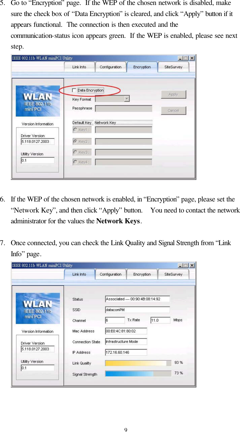
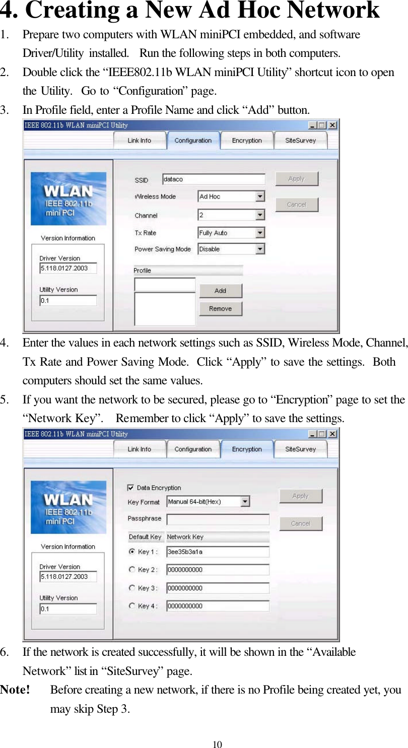
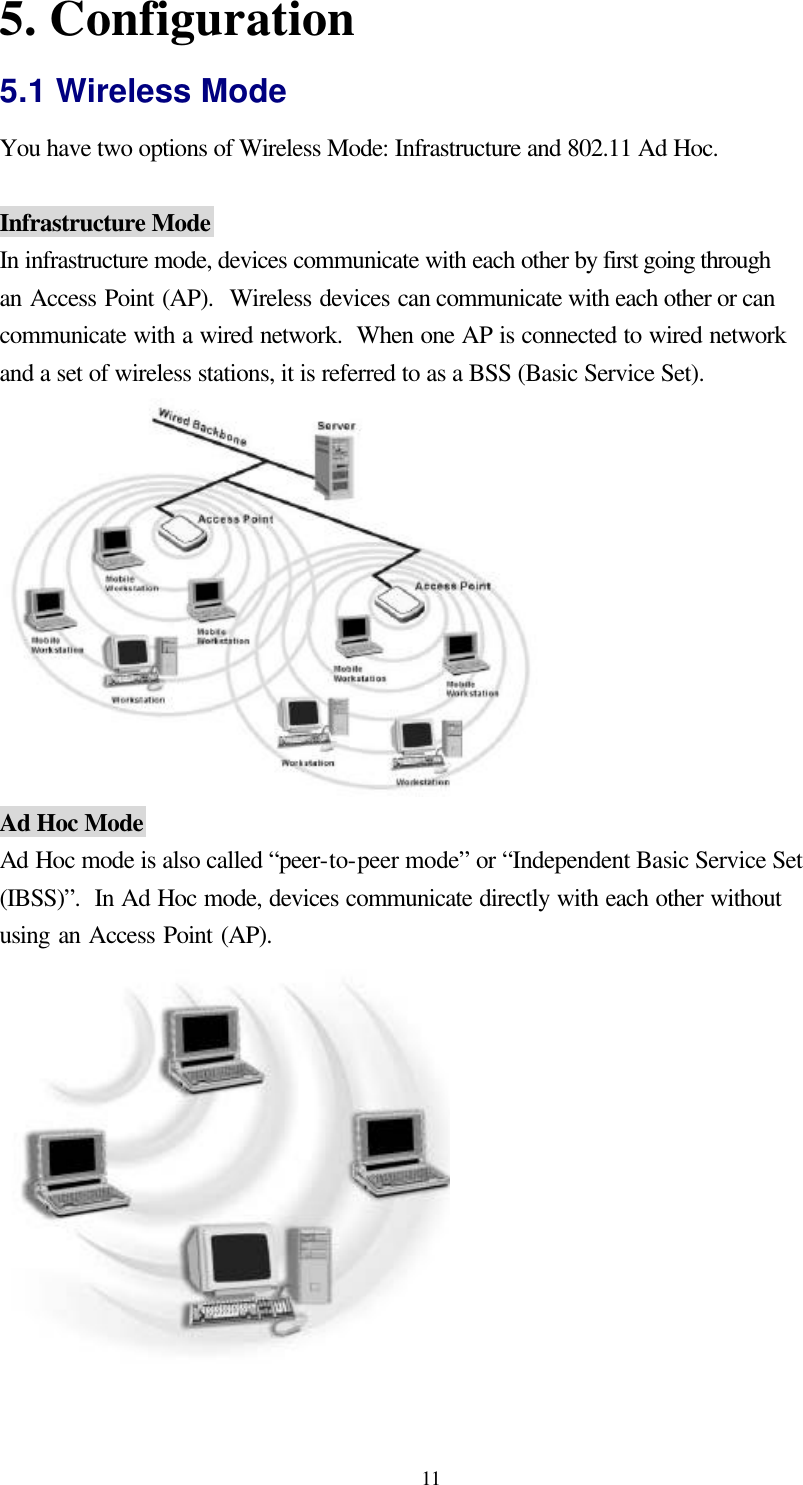
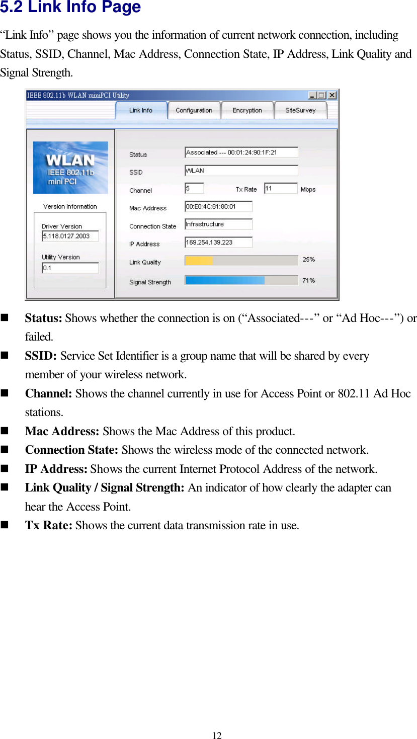
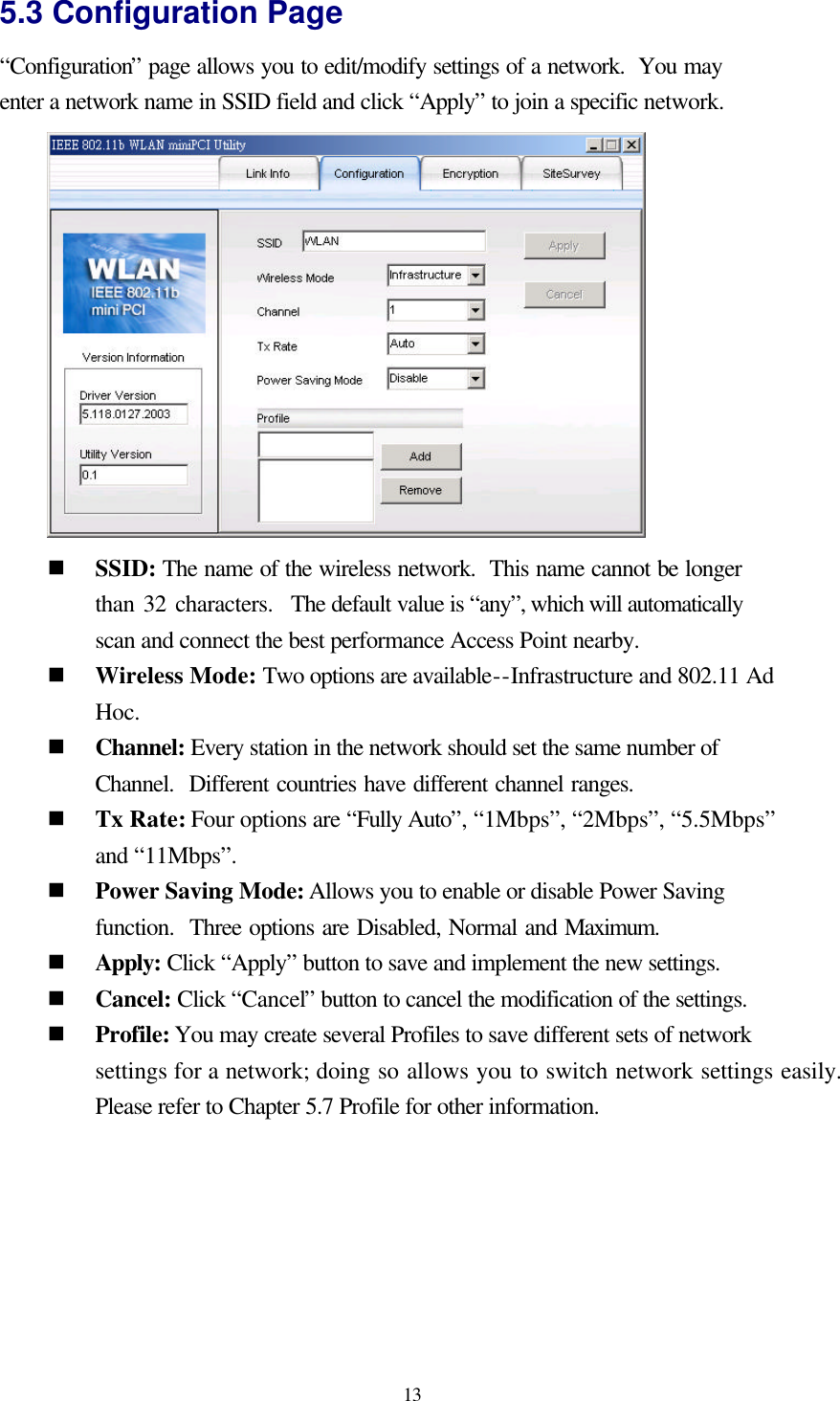
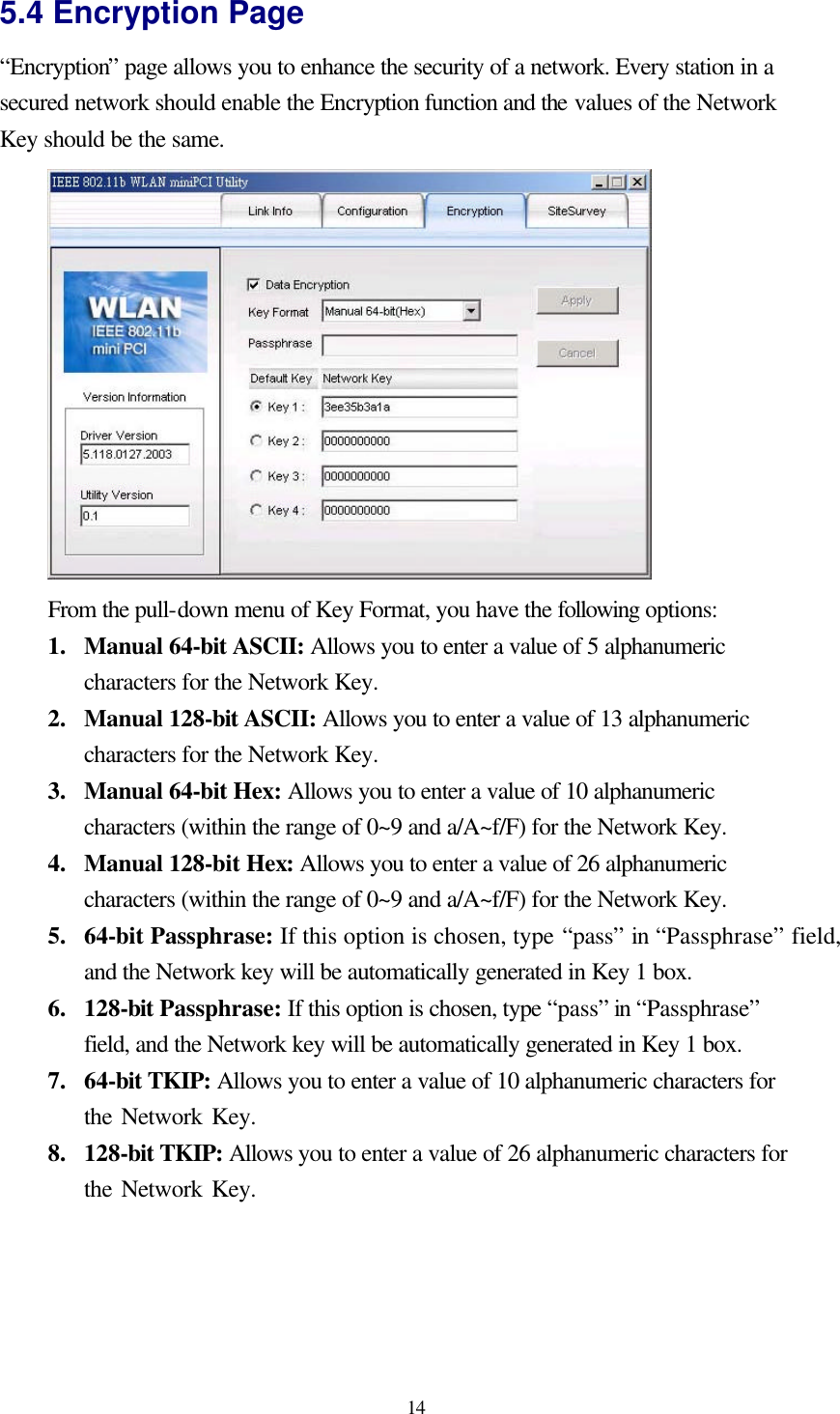
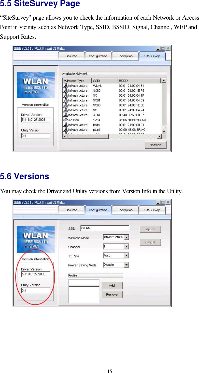
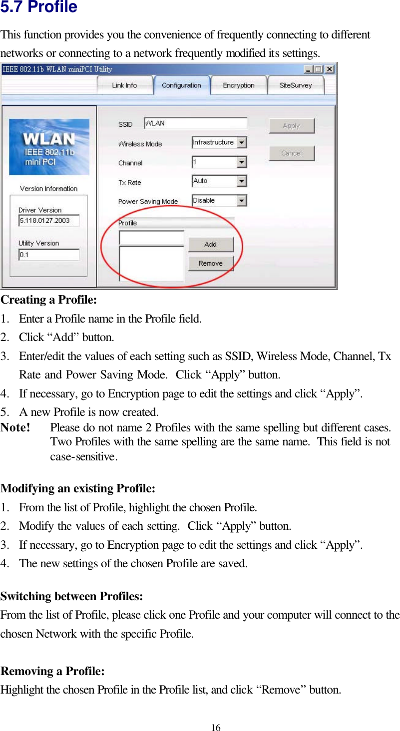
EM200B User Manual
OEM Manual revised
Navigation menu
Upload a User Manual
Namespaces
Wiki Guide
HTML
PDF
Info
Views
User Manual
Discussion / Help
Navigation