Wistron NeWeb EM200B 802.11b WLAN miniPCI User Manual manual 06062003 update
Wistron NeWeb Corporation 802.11b WLAN miniPCI manual 06062003 update
OEM Manual revised
IEEE 802.11b WLAN miniPCI
EM-200B
OEM Installation Manual
(The module is sold only to the OEM integrators & the
manual is valid only for the OEM manufactures)
Version: 1.0
April 2003
1
Copyright Statement
No part of this publication may be reproduced, stored in a retrieval system, or
transmitted in any form or by any means, whether electronic, mechanical,
photocopying, recording or otherwise without the prior writing of the publisher.
Windows™ 98SE/2000/ME/XP are trademarks of Microsoft® Corp.
Pentium is trademark of Intel.
All copyright reserved.
2
Federal Communication Commission Interference Statement
This equipment has been tested and found to comply with the limits for a Class
B digital device, pursuant to Part 15 of the FCC Rules. These limits are
designed to provide reasonable protection against harmful interference in a
residential installation. This equipment generates, uses and can radiate radio
frequency energy and, if not installed and used in accordance with
the instructions, may cause harmful interference to radio communications.
However, there is no guarantee that interference will not occur in a particular
installation. If this equipment does cause harmful interference to radio or
television reception, which can be determined by turning the equipment off and
on, the user is encouraged to try to correct the interference by one of the
following measures:
- Reorient or relocate the receiving antenna.
- Increase the separation between the equipment and receiver.
- Connect the equipment into an outlet on a circuit different from that to which
the receiver is connected.
- Consult the dealer or an experienced radio/TV technician for help.
FCC Caution: To assure continued compliance, (example - use only shielded
interface cables when connecting to computer or peripheral devices) any
changes or modifications not expressly approved by the party responsible for
compliance could void the user's authority to operate this equipment.
This device complies with Part 15 of the FCC Rules. Operation is subject to the
following two conditions:
(1) This device may not cause harmful interference, and
(2) This device must accept any interference received, including interference
that may cause undesired operation.
IMPORTANT NOTE:
This module is restricted to mobile configuration. To comply with FCC RF
exposure compliance requirements, the antenna used for this transmitter must
be installed to provide a separation distance of at least 20 cm from all persons
and must not be co-located or operating in conjunction with any other antenna
or transmitter. This transmitter module must not be co-located or operating in
conjunction with any other antenna or transmitter

3
TABLE OF CONTENTS
1. INTRODUCTION 4
2. HARDWARE INSTALLATION & ANTENNA INFORMATION5
CAUTION !! 6
3. CONNECTING TO AN EXISTING NETWORK 8
4. CREATING A NEW AD HOC NETWORK 10
5. CONFIGURATION 11
5.1 WIRELESS MODE 11
5.2 LINK INFO PAGE 12
5.3 CONFIGURATION PAGE 13
5.4 ENCRYPTION PAGE 14
5.5 SITESURVEY PAGE 15
5.6 VERSIONS 15
5.7 PROFILE 16
5.8 DEFAULT SETTINGS WINDOWS XP ZERO-CONFIGURATION 17
6. WIRELESS NETWORKING APPLICATIONS 18
6.1 SURVEYING THE NETWORK NEIGHBORHOOD 18
6.2 FILE SHARING 19
6.3 USING THE SHARED FOLDER 20
7. TROUBLESHOOTING 21
8. PRODUCT SPECIFICATION 22
4
1. Introduction
Thank you for purchasing the IEEE802.11b WLAN miniPCI that provides the easiest
way to wireless networking. This OEM Installation Manual contains detailed
instructions in the operation of this product. Please keep this manual for future
reference.
System Requirements
l A Personal Computer contains:
- 32 MB memory or greater
- 300 MHz processor or higher
l Microsoft® Win™98SE/ME/2000/ XP
5
2. Hardware Installation & Antenna
Information
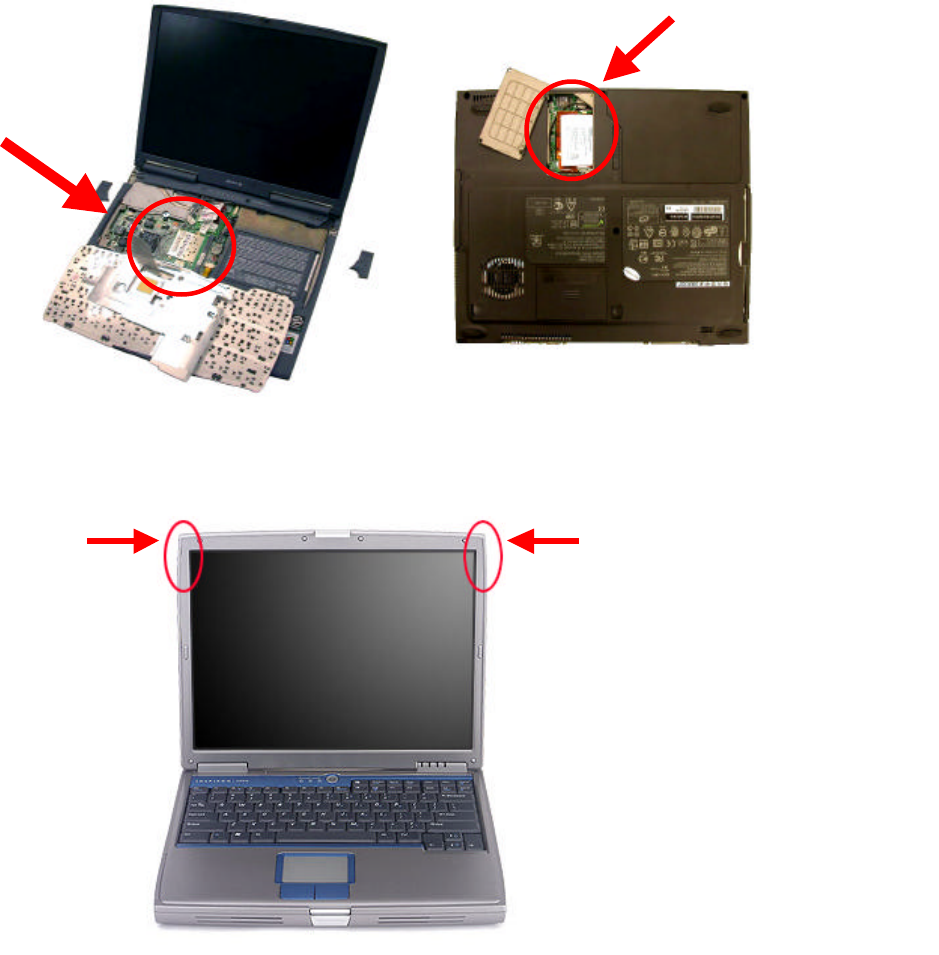
l Module is installed in the Personal Computer, located either under the keypad or
on the bottom side of the Personal Computer (see the following diagrams).
l Antennas are embedded in the top corners of the panel (see the two circles shown
below)
Important Note:
This module is restricted to mobile configuration. The antennas of module
should be installed and operated with minimum distance 20cm between the
radiator and all persons. This transmitter must not be co-located or operating in
conjunction with any other antenna or transmitter.
The module is for OEM installation only and can not be sold to end user directly.
Only the antenna types
listed below can be used.
1. CA8-I (WNC)
2. 5600 (CLEVO)
3. 888E (CLEVO)
4. M300N (CLEVO)

6
Caution !!
(1). This module cannot be bound in a tablet computer for RF
exposure issues. (See label 1)
(2). Due to the RF exposure issues, this module can be used in a
laptop computer in normal operation, but cannot be used when it is
put above the lap and the LCD screen is in the closed position.
(See label 2)
Label 1 Label 2
The device can’t be operated above
the lap when the LCD is closed

7
(3). This module must be labeled with FCC ID. (See label 3)
(4). If the FCC ID is not visible when the module is installed inside
another device, then the outside of device must also display a label
referring to the enclosed module. The exterior label can be
“ Contains Transmitter Module FCC ID: NKREM200B” or similar
wording. (See label 4)
Please put Label 2 & Label 4 to the enclosure of end
product to note the end user.
Label 3
Label 4
8
3. Connecting to an Existing Network
1. Double click the shortcut icon of “IEEE802.11b WLAN miniPCI Utility” on the
desktop, and the “IEEE802.11b WLAN miniPCI Utility” window will appear.
2. In the Windows System Tray, there is a communication-status icon that
indicates different connection statuses by showing different colors. Green
communication-status icon indicates the presence of a successful connection,
and your network connection process is complete.
3. Red communication-status icon indicates that no connection is present. In
this case, please go to “SiteSurvey” page and wait for a second (or click
“Refresh” button) to get a list of all available networks.
4. From the list of “Available Network”, double click one chosen network to
execute the connection.
9
5. Go to “Encryption” page. If the WEP of the chosen network is disabled, make
sure the check box of “Data Encryption” is cleared, and click “Apply” button if it
appears functional. The connection is then executed and the
communication-status icon appears green. If the WEP is enabled, please see next
step.
6. If the WEP of the chosen network is enabled, in “Encryption” page, please set the
“Network Key”, and then click “Apply” button. You need to contact the network
administrator for the values the Network Keys.
7. Once connected, you can check the Link Quality and Signal Strength from “Link
Info” page.
10
4. Creating a New Ad Hoc Network
1. Prepare two computers with WLAN miniPCI embedded, and software
Driver/Utility installed. Run the following steps in both computers.
2. Double click the “IEEE802.11b WLAN miniPCI Utility” shortcut icon to open
the Utility. Go to “Configuration” page.
3. In Profile field, enter a Profile Name and click “Add” button.
4. Enter the values in each network settings such as SSID, Wireless Mode, Channel,
Tx Rate and Power Saving Mode. Click “Apply” to save the settings. Both
computers should set the same values.
5. If you want the network to be secured, please go to “Encryption” page to set the
“Network Key”. Remember to click “Apply” to save the settings.
6. If the network is created successfully, it will be shown in the “Available
Network” list in “SiteSurvey” page.
Note! Before creating a new network, if there is no Profile being created yet, you
may skip Step 3.
11
5. Configuration
5.1 Wireless Mode
You have two options of Wireless Mode: Infrastructure and 802.11 Ad Hoc.
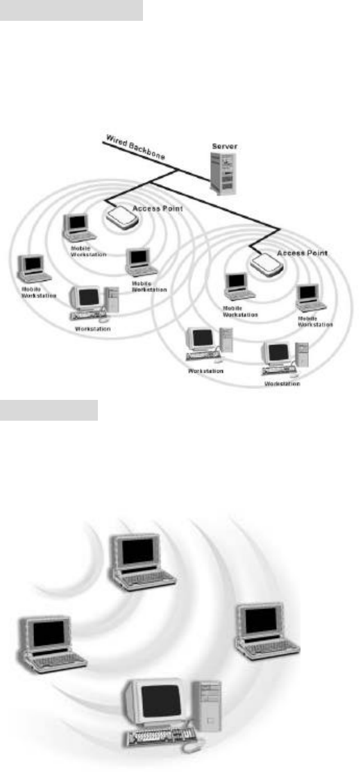
Infrastructure Mode
In infrastructure mode, devices communicate with each other by first going through
an Access Point (AP). Wireless devices can communicate with each other or can
communicate with a wired network. When one AP is connected to wired network
and a set of wireless stations, it is referred to as a BSS (Basic Service Set).
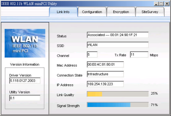
Ad Hoc Mode
Ad Hoc mode is also called “peer-to-peer mode” or “Independent Basic Service Set
(IBSS)”. In Ad Hoc mode, devices communicate directly with each other without
using an Access Point (AP).
12
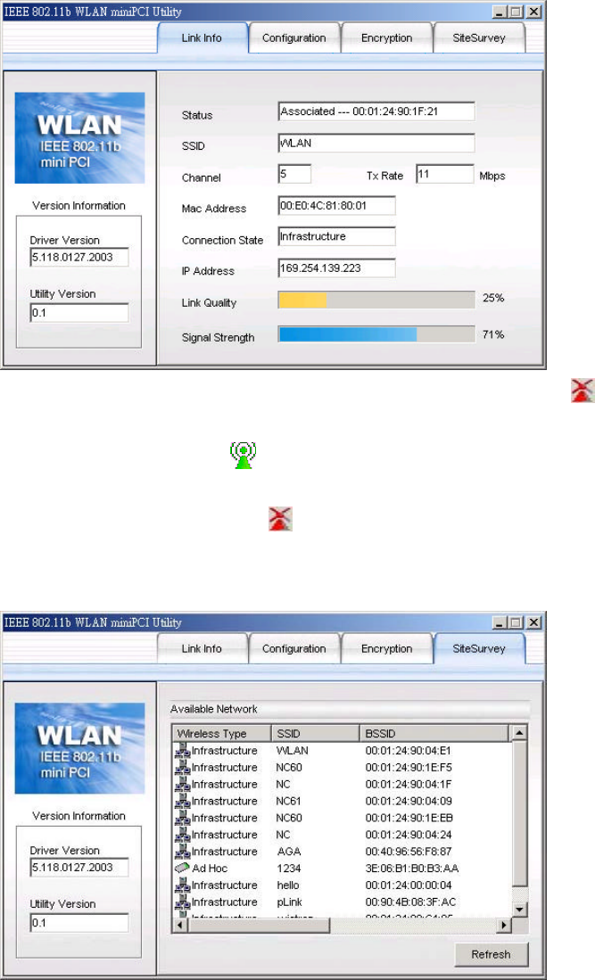
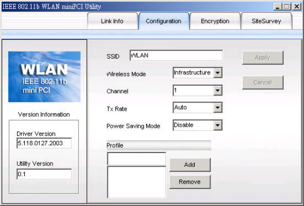
5.2 Link Info Page
“Link Info” page shows you the information of current network connection, including
Status, SSID, Channel, Mac Address, Connection State, IP Address, Link Quality and
Signal Strength.
n Status: Shows whether the connection is on (“Associated---” or “Ad Hoc---”) or
failed.
n SSID: Service Set Identifier is a group name that will be shared by every
member of your wireless network.
n Channel: Shows the channel currently in use for Access Point or 802.11 Ad Hoc
stations.
n Mac Address: Shows the Mac Address of this product.
n Connection State: Shows the wireless mode of the connected network.
n IP Address: Shows the current Internet Protocol Address of the network.
n Link Quality / Signal Strength: An indicator of how clearly the adapter can
hear the Access Point.
n Tx Rate: Shows the current data transmission rate in use.
13
5.3 Configuration Page
“Configuration” page allows you to edit/modify settings of a network. You may
enter a network name in SSID field and click “Apply” to join a specific network.
n SSID: The name of the wireless network. This name cannot be longer
than 32 characters. The default value is “any”, which will automatically
scan and connect the best performance Access Point nearby.
n Wireless Mode: Two options are available--Infrastructure and 802.11 Ad
Hoc.
n Channel: Every station in the network should set the same number of
Channel. Different countries have different channel ranges.
n Tx Rate: Four options are “Fully Auto”, “1Mbps”, “2Mbps”, “5.5Mbps”
and “11Mbps”.
n Power Saving Mode: Allows you to enable or disable Power Saving
function. Three options are Disabled, Normal and Maximum.
n Apply: Click “Apply” button to save and implement the new settings.
n Cancel: Click “Cancel” button to cancel the modification of the settings.
n Profile: You may create several Profiles to save different sets of network
settings for a network; doing so allows you to switch network settings easily.
Please refer to Chapter 5.7 Profile for other information.
14
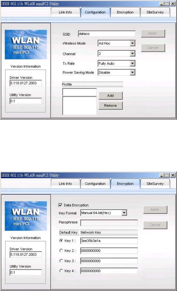
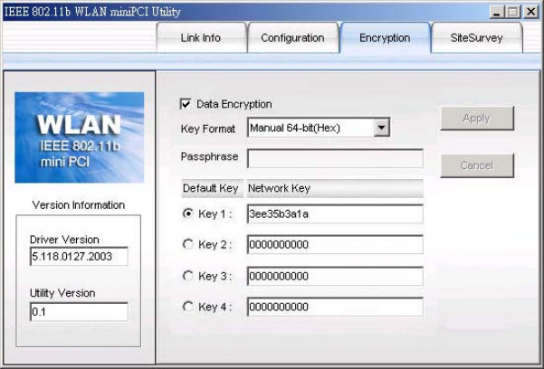
5.4 Encryption Page
“Encryption” page allows you to enhance the security of a network. Every station in a
secured network should enable the Encryption function and the values of the Network
Key should be the same.
From the pull-down menu of Key Format, you have the following options:
1. Manual 64-bit ASCII: Allows you to enter a value of 5 alphanumeric
characters for the Network Key.
2. Manual 128-bit ASCII: Allows you to enter a value of 13 alphanumeric
characters for the Network Key.
3. Manual 64-bit Hex: Allows you to enter a value of 10 alphanumeric
characters (within the range of 0~9 and a/A~f/F) for the Network Key.
4. Manual 128-bit Hex: Allows you to enter a value of 26 alphanumeric
characters (within the range of 0~9 and a/A~f/F) for the Network Key.
5. 64-bit Passphrase: If this option is chosen, type “pass” in “Passphrase” field,
and the Network key will be automatically generated in Key 1 box.
6. 128-bit Passphrase: If this option is chosen, type “pass” in “Passphrase”
field, and the Network key will be automatically generated in Key 1 box.
7. 64-bit TKIP: Allows you to enter a value of 10 alphanumeric characters for
the Network Key.
8. 128-bit TKIP: Allows you to enter a value of 26 alphanumeric characters for
the Network Key.
15
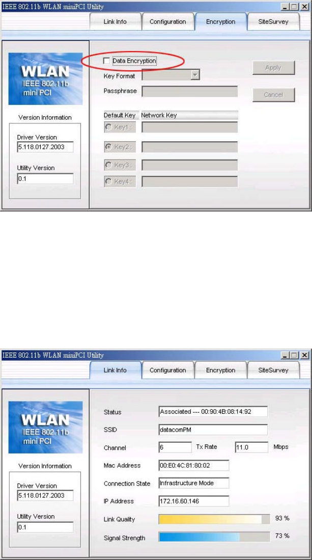
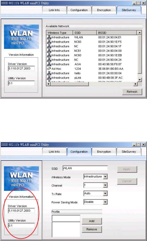
5.5 SiteSurvey Page
“SiteSurvey” page allows you to check the information of each Network or Access
Point in vicinity, such as Network Type, SSID, BSSID, Signal, Channel, WEP and
Support Rates.
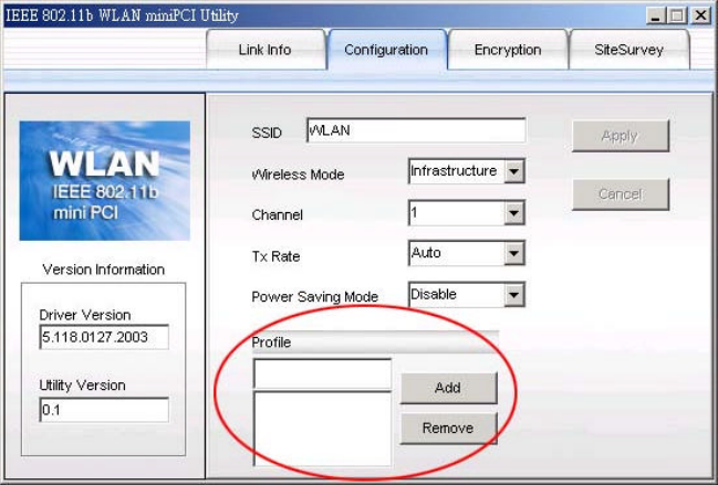
5.6 Versions
You may check the Driver and Utility versions from Version Info in the Utility.
16
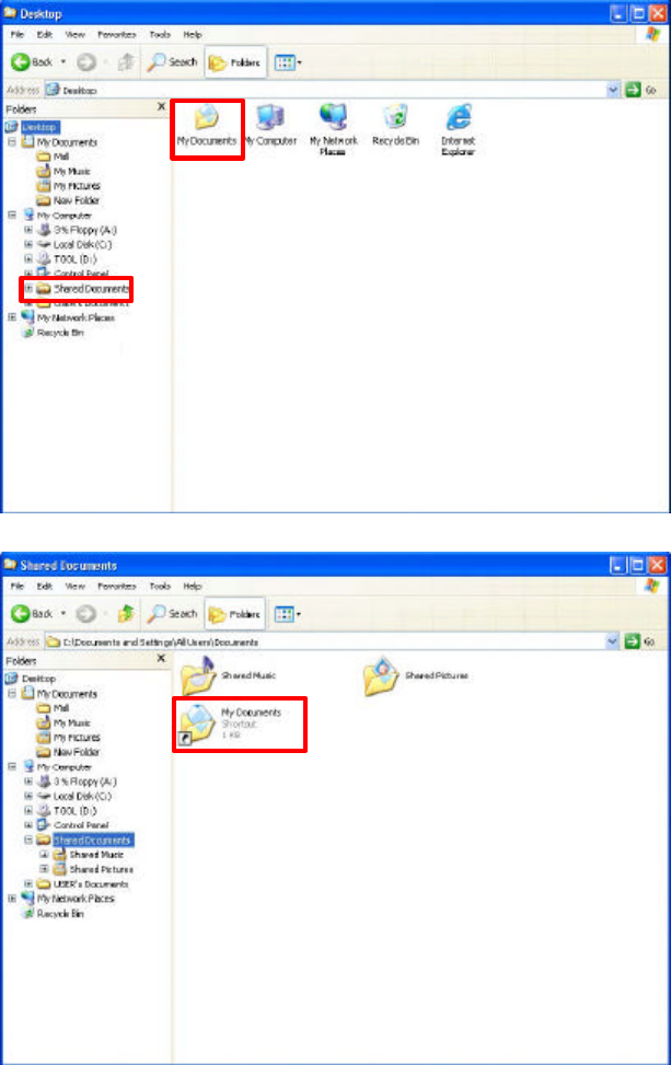
5.7 Profile
This function provides you the convenience of frequently connecting to different
networks or connecting to a network frequently modified its settings.
Creating a Profile:
1. Enter a Profile name in the Profile field.
2. Click “Add” button.
3. Enter/edit the values of each setting such as SSID, Wireless Mode, Channel, Tx
Rate and Power Saving Mode. Click “Apply” button.
4. If necessary, go to Encryption page to edit the settings and click “Apply”.
5. A new Profile is now created.
Note! Please do not name 2 Profiles with the same spelling but different cases.
Two Profiles with the same spelling are the same name. This field is not
case-sensitive.
Modifying an existing Profile:
1. From the list of Profile, highlight the chosen Profile.
2. Modify the values of each setting. Click “Apply” button.
3. If necessary, go to Encryption page to edit the settings and click “Apply”.
4. The new settings of the chosen Profile are saved.
Switching between Profiles:
From the list of Profile, please click one Profile and your computer will connect to the
chosen Network with the specific Profile.
Removing a Profile:
Highlight the chosen Profile in the Profile list, and click “Remove” button.
17
5.8 Default Settings Windows XP Zero-Configuration
You may also choose the default parameters and directly proceed to Windows XP
zero-configuration through the steps below:
1. Go to “Control Panel” and open “Network Connections”.
2. Right-click the Wireless Network Connection of the IEEE802.11b WLAN
miniPCI, and make sure this connection is Enabled.
3. Right-click the Wireless Network Connection of the IEEE802.11b WLAN
miniPCI, and then click “Properties”.
4. Select “Wireless Networks” tab and select “Use Windows to configure my
wireless network settings” check box.
Note! Clear the check box of “Use Windows to configure my wireless network
settings” will disable automatic wireless network configuration.
18
6. Wireless Networking Applications
Available network applications are as follows:
l To Survey the network neighborhood
l To Share Your Folder with Your Network Member(s)
l To Share Your Printer with Your Network Member(s)
l To Access the Shared Folder(s)/File(s) of Your Network Members(s)
l To Use the Shared Printer(s) of Your Network Member(s)
In fact, the network applications of the IEEE802.11b WLAN miniPCI are the same as
they are in a wired network environment. You may refer to the following 3
examples of Surveying the Network Neighborhood, File Sharing and Using the
Shared Folder.
6.1 Surveying the Network Neighborhood
When multiple base stations are up and running in your wireless network, you can use
the procedure described below to display the other computers:
1. Double-click My Network Places to display all stations in your Microsoft
Windows Network Group.
2. To display other workgroups in the network environment, double-click Entire
Network.
3. If there is a second network operating system running in your network
environment (for example a Novell NetWare network), the “Entire Network”
window will also display available servers running under the second network
operating system. If you click on these servers, you may be asked to enter
your user name and password that applies to the other network operating
system. If you cannot find it, verify whether the other wireless computers are:
l Powered up and logged on to the network.
l Configured to operate with identical Microsoft Network settings
concerning:
n Networking Protocol.
n Wireless Network Name.
To enable the sharing of Internet access, you should set the WLAN mode as
“Infrastructure” and connect to the access point.
19
6.2 File Sharing
You may share files between computers that are logged onto the same wireless
network. For example, if you want to share your folder “My Documents“ with other
computers of the wireless network, please highlight the folder “My Documents”
and drag it to Shared Documents folder.
Sharing files in the IEEE802.11b wireless network will be like sharing files on a
wired LAN.
20
6.3 Using the Shared Folder
If you would like to access a shared folder stored in other stations of the same
network, please follow the process below:
1. Double-click the “My Network Places” icon, and then double-click the
computer where the shared folder is located.
2. Double-click the folder you want to connect to.
3. Now you may open the needed file(s).
Note! If a password is required, the Windows will prompt a password column.
Please enter the password that had been assigned to this shared folder.

21
7. Troubleshooting
Problems Possible Solutions
n My computer cannot find the Adapter 1. Make sure the miniPCI is properly
embedded.
2. Check whether there are conflicts
caused by other network cards in the
computer: Remove all network cards
and try again.
n Cannot access any network resources
from the computer.
1. Make sure the correct software is
installed.
2. Make sure all network devices are
receiving power and working well.
3. Check whether the SSID is set
properly.
4. Check with the network administrator
to see whether the Access Point is
configured properly to accept your
signal.
5. If you have trouble accessing the
Internet, make sure to check with the
ISP (Internet Service Provider) for
further instructions.
6. Select long preamble instead of short
preamble if your Access Point has this
function, and try the connection again.

22
8. Product Specification
Frequency range 2.4G ~ 2.4835Ghz
Modulation technique DSSS (Direct Sequence Spread Spectrum) with
BPSK (1Mbps), QPSK (2Mbps), and CCK (5.5 and
11Mbps)
Operation voltage 3.3V +/- 10%
Power consumption - Transmission mode: 300mA
- Receives mode: 180A
- Sleep mode: 20mA
Output power 13-17dBm
Operation range - Indoor: 35 ~100 meter
- Outdoor: 200- 350 meter
Sensitivity @PER <0.08
11Mbps < -84dBm
5.5Mbps < -86dBm
2Mbps < -88dBm
1Mbps < -90dBm
Operation system Windows 98SE, Me,2K, XP
Security 64-bit , 128-bit WEP encryption
Transfer data rate 11Mbps, 5.5Mbps, 2Mbps, 1Mbps , auto-rate
Operation temperature
range
0oC ~ 60oC
Storage temperature
range
-20oC ~ 65oC
Humidity
(non-condensing)
5% ~90%
Warranty 1 year standard warranty, 3 years optional
EMC certificate - FCC Class B part 15.247 (USA)
- IC RSS210 (Canada)
- ETSI 300 328, ETSI300 826 (Europe)
- ARIB STD-T66, RCR STD-33 (Japan, subject to
customer’s request)
Media access protocol CSMA/CA with ACK
Antenna Support antenna diversity