Wistron NeWeb LMLORA UMC-LORA User Manual 1
Wistron NeWeb Corporation UMC-LORA 1
User Manual

Subject: UMC-LORA User Manual REV: 2.0
PAGE 1 OF 17
Wistron Neweb Corporation Proprietary & Confidential
Design Document
UMC-LORA User Manual
The document contains proprietary information which is the property of Wistron NeWeb
Corporation and is strictly confidential and shall not be disclosed to others in whole or in
part, reproduced, copied, or used as basic for design, manufacturing or sale of apparatus
without the written permission of Wistron NeWeb Corporation.
Subject: UMC-LORA User Manual REV: 2.0
PAGE 2 OF 17
Wistron Neweb Corporation Proprietary & Confidential
Design Document
Revision History
Issue Date
Version
Description
2017/08/31
1.0
Initial Issued
2017/10/24
2.0
Updated according to reviewer
2017/10/31
3.0
Update OEM installation statement

Subject: UMC-LORA User Manual REV: 2.0
PAGE 3 OF 17
Wistron Neweb Corporation Proprietary & Confidential
Design Document
Contents
1. Introduction .......................................................................................................................................... 4
2. Test Setup Configuration ..................................................................................................................... 6
2.1 Power Supply and Debug Console Connection ...................................................................... 6
2.2 RF Connection ........................................................................................................................... 9
2.3 Hardware Component Introduction ..................................................................................... 10
3. Installation and Test Method ..............................................................................................................11
3.1 Attach UMC-LORA card onto SMCC........................................................................................11
3.2 Install GDM7243 Driver ......................................................................................................... 13
3.3 Confirm the GDM7243 device ............................................................................................... 13
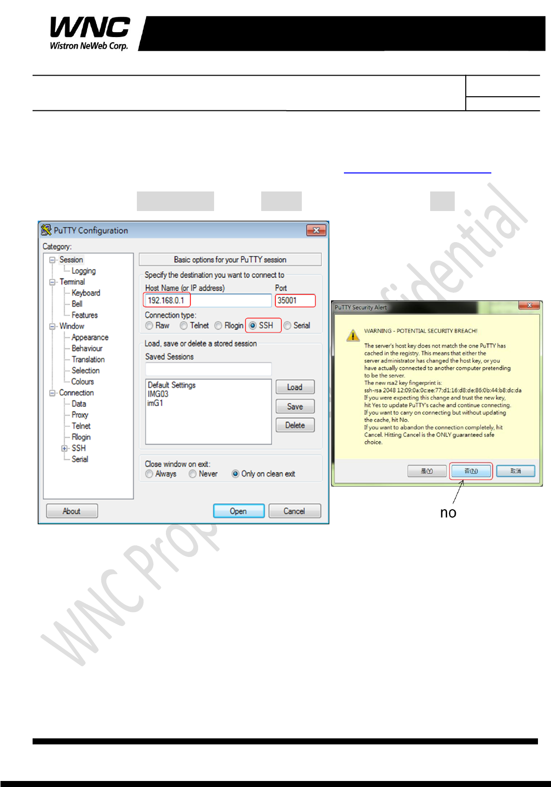
3.4 Open the com port by PuTTy ................................................................................................. 14
3.5 Lora Test Command ............................................................................................................... 16
4. Test Equipment ................................................................................................................................... 17
5. Antenna performance ........................................................................................................................ 17

Subject: UMC-LORA User Manual REV: 2.0
PAGE 4 OF 17
Wistron Neweb Corporation Proprietary & Confidential
Design Document
1. Introduction
This User Manual of ISM module is to describe how to use the following sections for
lab test by specific qualified engineers or technicians. Furthermore, this module is NOT
intended for commercial use but designed as part of Smart Meter product which mainly
provides ISM-900 access capabilities. For the procedure of SMCC installation into electric
meter and the operation of SMCC in assembly factory, that information is described in
assembly instruction document.
FCC ID Location
FCC ID is placed in manual instead of label area, for the reason that the device is too
small to have FCC ID been properly placed on label area, because of over crowded
identification of other product and regulatory information.
Model : UMC-LORA
P/N: 81.UMCLORA.G01
FCC ID: NKR-LMLORA
FCC Interference Statement
This module complies with Part 15 of the FCC Rules. Operation is subject to the
following two conditions: (1) This module may not cause harmful interference and (2) this
module must accept any interference received, including interference that may cause
undesired operation.
FCC Statement for a Class B digital device or peripheral,
This equipment has been tested and found to comply with the limits for a Class B digital
device, pursuant to part 15 of the FCC Rules. These limits are designed to provide
reasonable protection against harmful interference in a residential installation. This
equipment generates, uses and can radiate radio frequency energy and, if not installed
and used in accordance with the instructions, may cause harmful interference to radio
communications. However, there is no guarantee that interference will not occur
in a particular installation. If this equipment does cause harmful interference to radio or

Subject: UMC-LORA User Manual REV: 2.0
PAGE 5 OF 17
Wistron Neweb Corporation Proprietary & Confidential
Design Document
television reception, which can be determined by turning the equipment off and on, the
user is encouraged to try to correct the interference by one or more of the following
measures:
—Reorient or relocate the receiving antenna.
—Increase the separation between the equipment and receiver.
—Connect the equipment into an outlet on a circuit different from that to which the
receiver is connected.
—Consult the dealer or an experienced radio/ TV technician for help.
Radiation Exposure Statement
This module complies with FCC radiation exposure limits set forth for an uncontrolled
environment. This module should be installed and operated with minimum distance of
20cm between radiator and human body.
Any changes or modifications not expressly approved by the party responsible for
compliance could void the user’s authority to operate the device.
Subject: UMC-LORA User Manual REV: 2.0
PAGE 6 OF 17
Wistron Neweb Corporation Proprietary & Confidential
Design Document
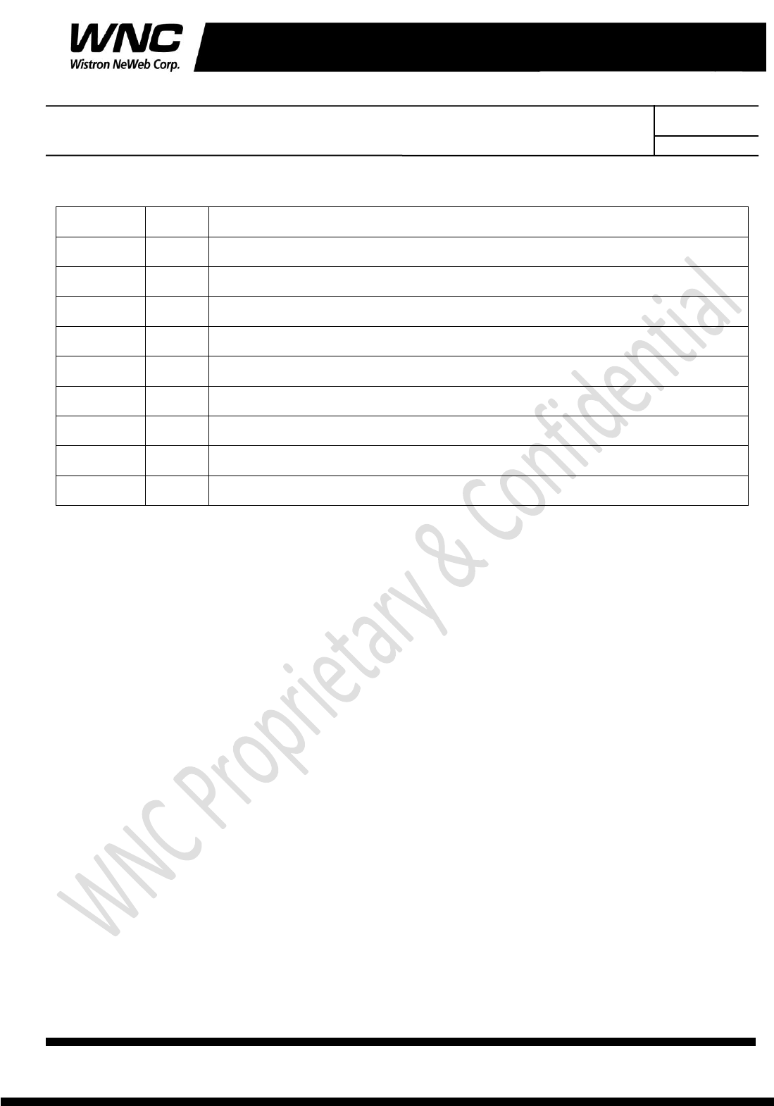
2. Test Setup Configuration
2.1 Power Supply and Debug Console Connection
10 pin Connect to interface board
Don’t care last 2 pin
CB
Interface Board
Subject: UMC-LORA User Manual REV: 2.0
PAGE 7 OF 17
Wistron Neweb Corporation Proprietary & Confidential
Design Document
AC-DC 5V Adaptor
Interface Board
CB
USB Debug Port Console
UMC-LORA (DUT)

Subject: UMC-LORA User Manual REV: 2.0
PAGE 8 OF 17
Wistron Neweb Corporation Proprietary & Confidential
Design Document
Power on Sequence:
I. Connect DUT to interface board
II. Attach AC-DC Adaptor & USB Debug Port Cable
III. Wait for 20 seconds when system ready
Subject: UMC-LORA User Manual REV: 2.0
PAGE 9 OF 17
Wistron Neweb Corporation Proprietary & Confidential
Design Document
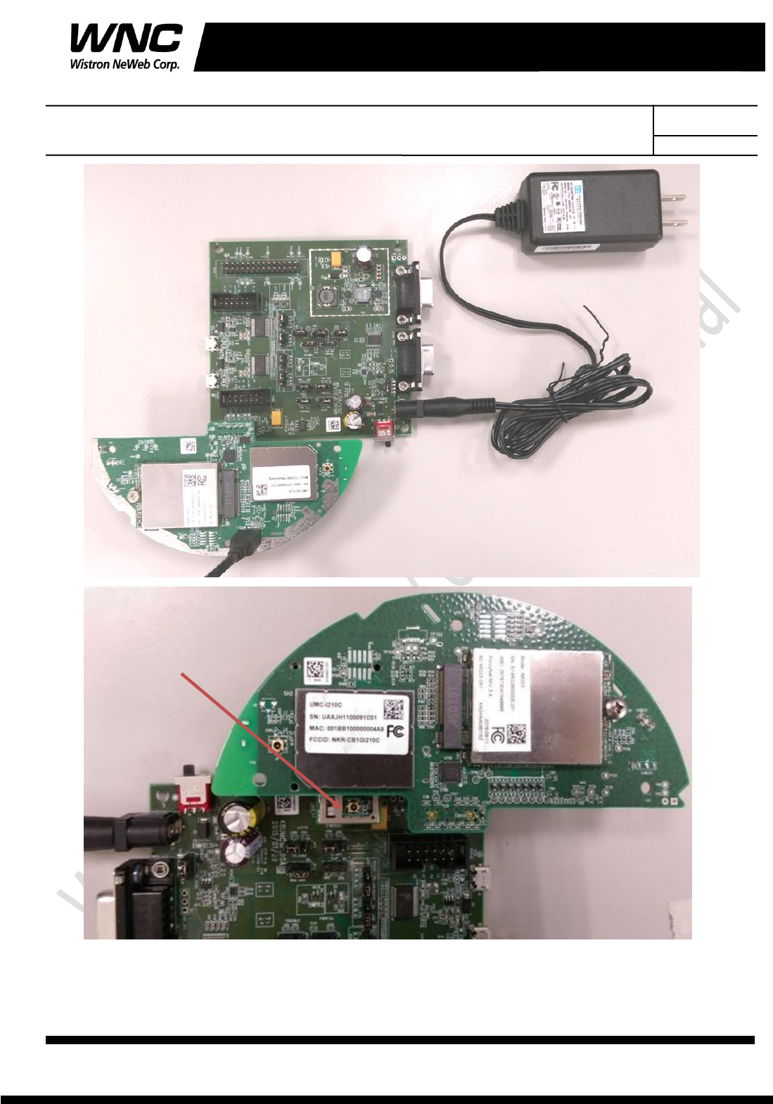
2.2 RF Connection
Connection for LORA internal antenna
Connection for conducted test
Subject: UMC-LORA User Manual REV: 2.0
PAGE 10 OF 17
Wistron Neweb Corporation Proprietary & Confidential
Design Document
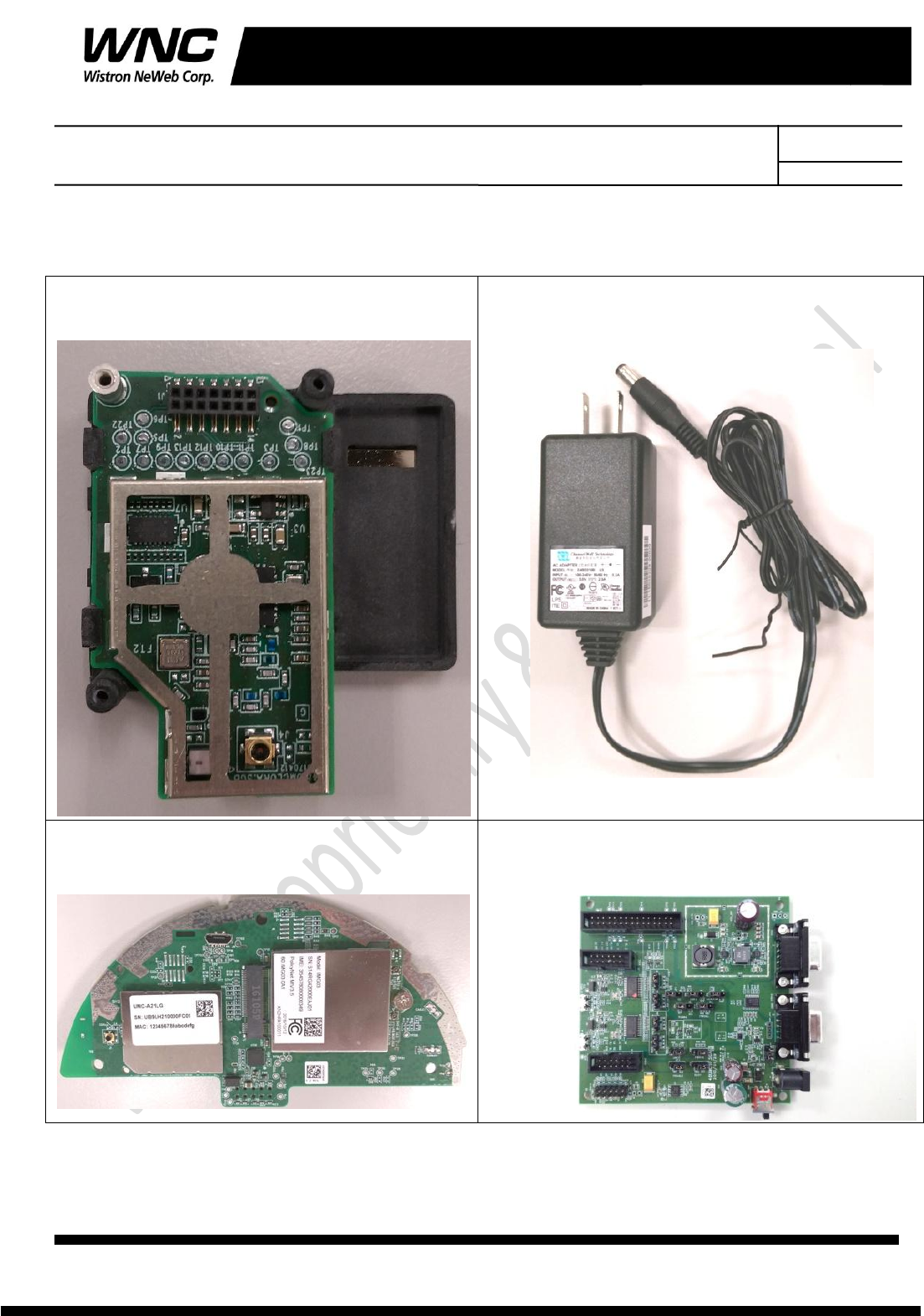
2.3 Hardware Component Introduction
LORA card (DUT)
AC/DC Adaptor
SMCC
Interface Board
Subject: UMC-LORA User Manual REV: 2.0
PAGE 11 OF 17
Wistron Neweb Corporation Proprietary & Confidential
Design Document
3. Installation and Test Method
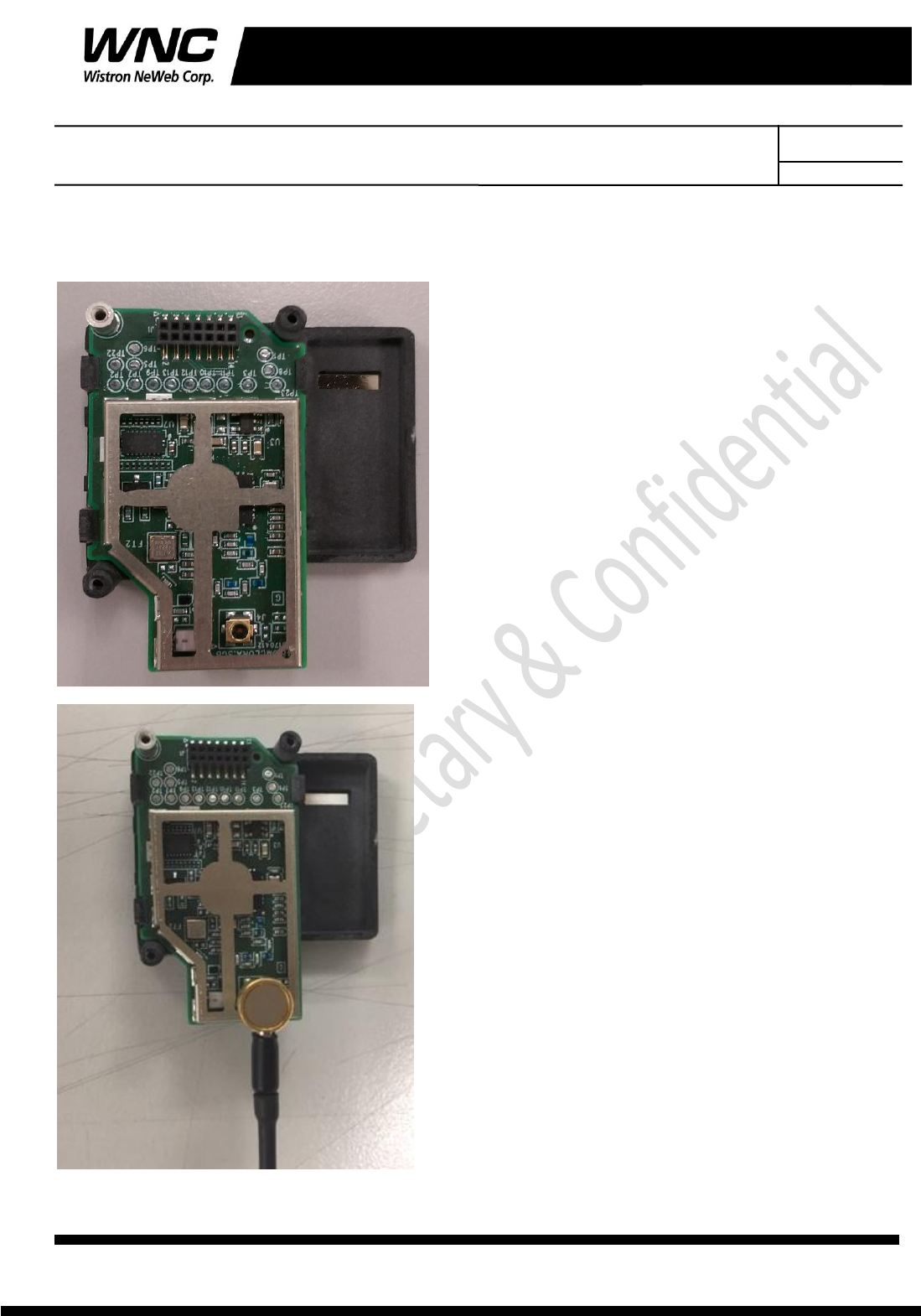
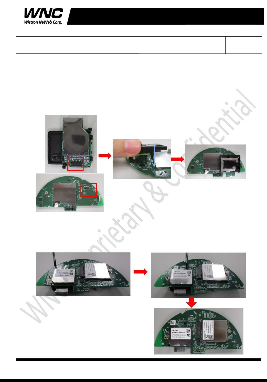
3.1 Attach UMC-LORA card onto SMCC
Step 1 : Connect the board to board connector
To invert Lora card and combine the female & male connector.
Step 2 : Fix the Lora card
To invert SMCC and screw 3 screws at indicated points on SMCC with Lora card. The black
screw is corresponding to the SMT nut and the silver screws are corresponding to the
holder bosses.

Subject: UMC-LORA User Manual REV: 2.0
PAGE 12 OF 17
Wistron Neweb Corporation Proprietary & Confidential
Design Document
OEM installation statement:
This device is intended only for OEM integrators under the following conditions:
1) The antenna must be installed such that 20 cm is maintained between the
antenna and users. For laptop installations, the antenna must be installed to ensure that
the proper spacing is maintained in the event the users places the device in their lap
during use (i.e. positioning of antennas must be placed in the upper portion of the LCD
panel only to ensure 20 cm will be maintained if the user places the device in their lap for
use) and
2) The transmitter module may not be co-located with any other transmitter or
antenna. As long as the 2 conditions above are met, further transmitter testing will not
be required. However, the OEM integrator is still responsible for testing their
end-product for any additional compliance requirements required with this module
installed (for example, digital device emissions, PC peripheral requirements, etc.).
IMPORTANT NOTE: In the event that these conditions cannot be met (for example
certain laptop configurations or co-location with another transmitter), then the FCC
authorization is no longer considered valid and the FCC ID cannot be used on the final
product. In these circumstances, the OEM integrator will be responsible for re-evaluating
the end product (including the transmitter) and obtaining a separate FCC authorization.
End Product Labeling:
This transmitter module is authorized only for use in devices where the antenna may
be installed such that 20 cm may be maintained between the antenna and users (for
example access points, routers, wireless ASDL modems, certain laptop configurations, and
similar equipment). The final end product must be labeled in a visible area with the
following: "Contains TX FCC ID: {INSERT FCC ID HERE}".
RF Exposure Manual Information That Must be Included:
The users manual for end users must include the following information in a prominent
location "IMPORTANT NOTE: To comply with FCC RF exposure compliance requirements,
the antenna used for this transmitter must be installed to provide a separation distance of
at least 20 cm from all persons and must not be co-located or operating in conjunction
with any other antenna or transmitter."
Additional Information That Must be Provided to OEM Integrators:
The end user should NOT be provided any instructions on how to remove or install
the device.
Subject: UMC-LORA User Manual REV: 2.0
PAGE 13 OF 17
Wistron Neweb Corporation Proprietary & Confidential
Design Document
3.2 Install GDM7243 Driver
Install the GDM7243 driver “GDM7243_windows_acm_drivers_installer_v1.1.0.0.zip”
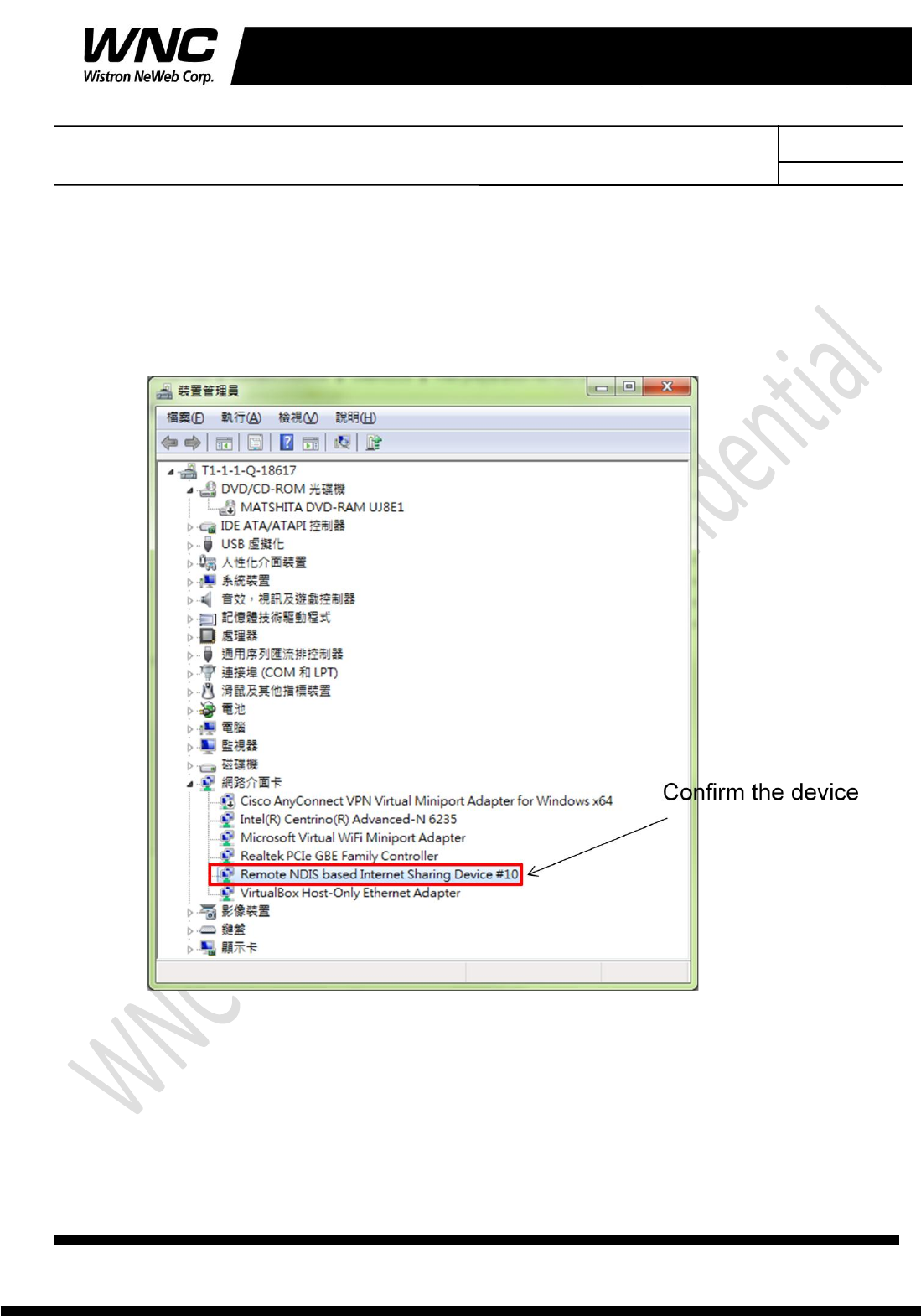
3.3 Confirm the GDM7243 device
Confirm the com port “Remote NDIS based Internet Sharing Device ” in the Device Manager.
Subject: UMC-LORA User Manual REV: 2.0
PAGE 15 OF 17
Wistron Neweb Corporation Proprietary & Confidential
Design Document
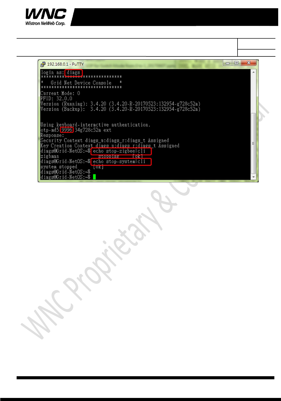
1. Login as: diags
2. Find the one time password(OTP) with prompt number
3. Ex: 9998: IDLE EYED MATE MID MAGI DIRT
4. Enter command: echo stop-zigbee|cli
5. Enter command: echo stop-system|cli
OTP List:
9998: IDLE EYED MATE MID MAGI DIRT
9997: ACRE BULK MILE BOLO WAYS WOVE
9996: CHOU PAW OATH KANE ORE TERN
9995: NAG JIVE OS MUM LION HOBO
9994: SON DEAN MONK MAW LUCY ACRE
9993: BLUE FLAT LAWN HID TEET BOCK
9992: SOLD KIRK BOSS LULU INK ROOK
9991: SHOE OUST CASH ALAN ROSE LUSH
9990: CUBA HOLD HERB JUJU FUSS GAUL
9989: RITE FLAT TOOL HUM SEEK OS
9988: DOWN MITT FISK CAGE GEL MUCH
9987: HIGH DRY TORN LOY LUSH FROM
9986: SNOW FAWN LAME MURK BED EAT
Subject: UMC-LORA User Manual REV: 2.0
PAGE 16 OF 17
Wistron Neweb Corporation Proprietary & Confidential
Design Document
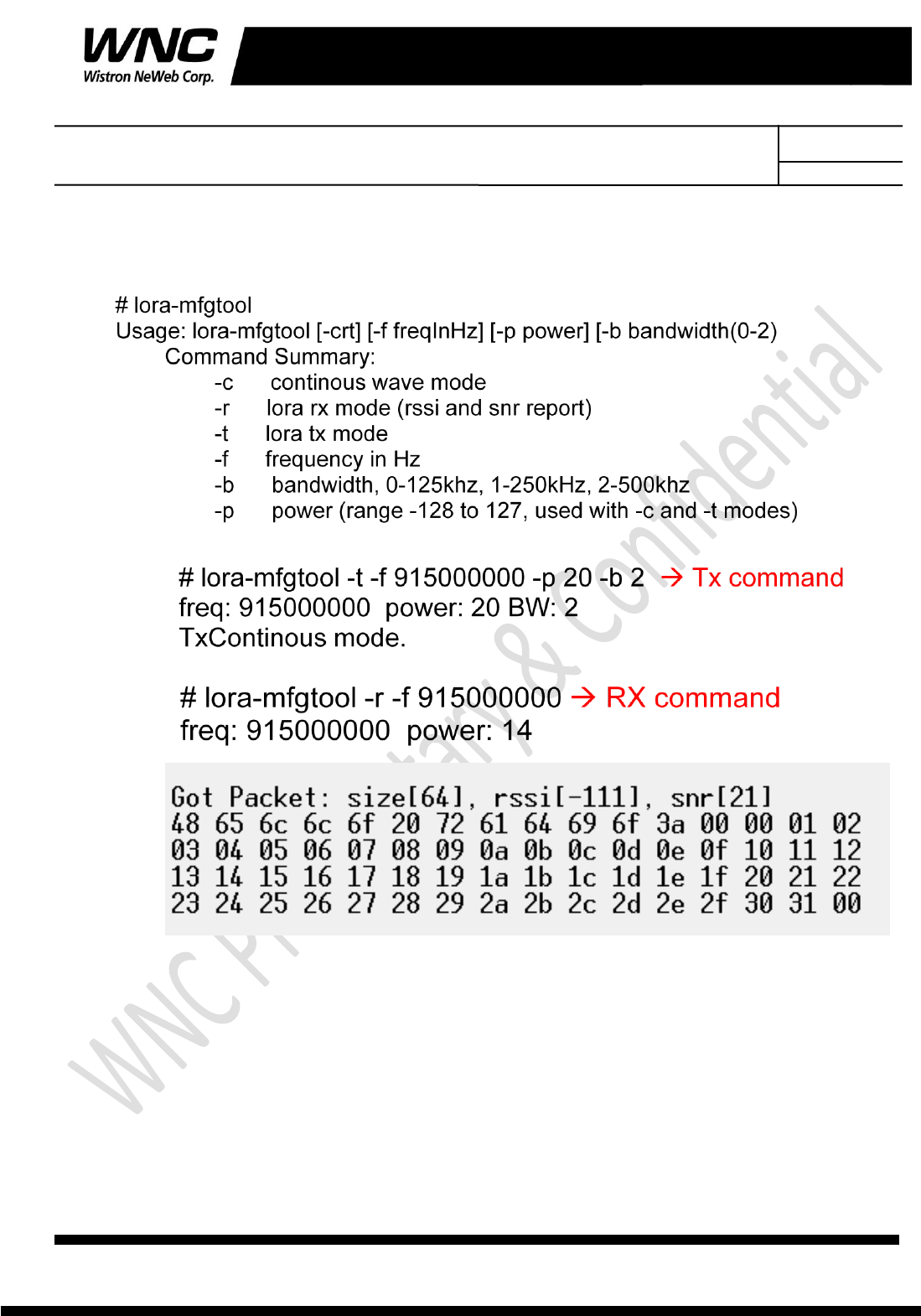
3.5 Lora Test Command
Subject: UMC-LORA User Manual REV: 2.0
PAGE 17 OF 17
Wistron Neweb Corporation Proprietary & Confidential
Design Document
4. Test Equipment
It is suggested to use Anritsu MT2830C for RF conductive tests.setc
5. Antenna performance
For ISM radiation tests, the ISM antenna gain shows in below table.
Frequency(MHz)
Average Gain(dB)
Peak Gain(dB)
Efficiency(%)
902
-5.16
1.03
30%
905
-5.18
0.97
30%
910
-5.09
0.84
31%
915
-5.18
0.73
30%
920
-5.19
0.7
30%
925
-5.28
0.58
30%
928
-5.25
0.57
30%