Wistron NeWeb OR8400 High End RFID Reader module User Manual OR8400 FCC V0 3
Wistron NeWeb Corporation High End RFID Reader module OR8400 FCC V0 3
UserManual.wiki
>
Wistron NeWeb
>
OR8400 User Manual
User Manual.pdf
Navigation menu
Upload a User Manual
Namespaces
Wiki Guide
HTML
PDF
Info
Views
User Manual
Discussion / Help
Navigation
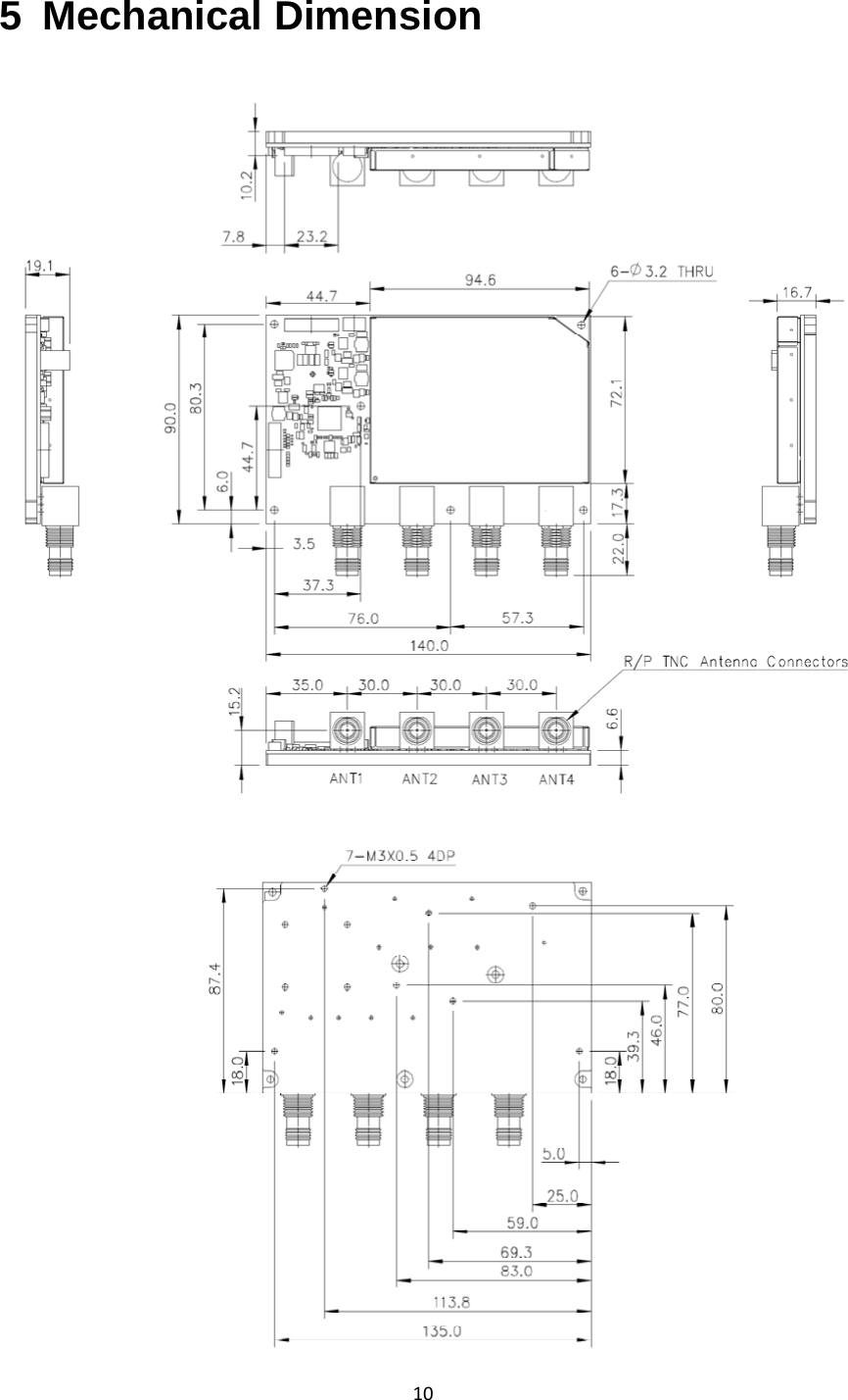
![43 Specification OR8400SpecificationAirInterfaceProtocolEPCglobalUHFClass1Gen2/ISO18000‐6CTransmitPower+10.0to+30.0dBmMax.ReceiveSensitivity[1] ‐82dBmTypicalReceiveSensitivity[1]‐84dBmat30dBm‐86dBmat27dBmMin.ReturnLoss10dBAntennaports4reversepolarityTNCmono‐staticportsDenseReaderMode SupportDenseReaderMode(DRM),Built‐inDRMFilterPerformanceoptimization SupportAutoimprovingsensitivitytechnologyFrequency US:902~928MHzInterfaceUSB1.1(USB2.0FullSpeed)USBDriverSupportWindowsXP/7/Linux32bitDCPower 12V+/‐5%PowerConsumption12Wat30.0dBmOperatingCaseTemperature[2]‐20 oCto+70oCHumidity5%to95%,non‐condensingDimensions 140x90mm(notincludeTNCconnector)RoHSComplianttoEuropeanUniondirective2002/95/ECNote:[1]SensitivityvalueismeasuredbyVoyanticReadformanceatTNCconnectors.[2]The OR8400 module may be considered as a single electronic component. It is designed so that all the internal components have safe margins to their thermal limits when the heat spreading plate (bottom) does not exceed 70°C. The heat spreading plate temperature must not exceed 70 degrees C. Heat sinking will be required for high duty cycle applications.](https://usermanual.wiki/Wistron-NeWeb/OR8400/User-Guide-2398256-Page-4.png)