Wistron NeWeb OR8400 High End RFID Reader module User Manual OR8400 FCC V0 3
Wistron NeWeb Corporation High End RFID Reader module OR8400 FCC V0 3
User Manual.pdf

1
OR8400UserManual
(V0.3)
ModelName:OR8400
Description:UHFRFIDReaderModule
Edition#ReasonforrevisionIssuedate
V0.1Firstrelease2014/06/18
V0.2Modifyreturnloss2014/07/03
V0.3ModifiedforFCC
This document contains proprietary information which is the property of Wistron
NeWeb Corporation and is strictly confidential and shall not be disclosed to others
in whole or in part, reproduced, copied, or used as basic for design, manufacturing or
sale of apparatus without the written permission of Wistron NeWeb Corporation.
2
CONTENTS
1Introduction .......................................................................................................... 3
2Hardware Block Diagram ................................................................................... 3
3Specification ......................................................................................................... 4
4Hardware interfaces ............................................................................................ 7
4.1Antenna Connections ................................................................................. 7
4.1.1AntennaRequirements..................................................................7
4.1.2AntennaDetection.........................................................................7
4.2Digital/Power Connector Definition .......................................................... 7
4.2.1Antennastatussignals...................................................................9
4.2.2LEDsignal.......................................................................................9
5Mechanical Dimension ...................................................................................... 10
3
1 Introduction
OR8400 is a superior, high sensitivity and high performance 4 ports
RFID reader module with built-in Impinj Indy R2000 RFID reader chip.
OR8400 supports EPC class1 Gen2/ ISO 18000-C. The maximum RF
output power is 30.0dBm. The typical sensitivity is -84dBm at 30dBm output
power.
OR8400 supports auto sensitivity improving technology. It can improve
more than 10dB sensitivity.
In summary, the R2000 RFID chip was chosen because it provided the
very best basic performance. The RF section was optimized by using a
circulator. Thus, the combination of the R2000 chip and circulator based RF
section with auto sensitivity improving technology provides the very best
performance possible. Therefore, OR8400 is superior to all other R2000
base designs.
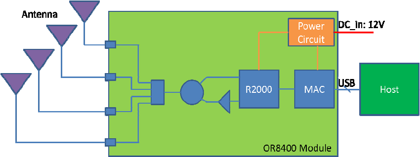
2 Hardware Block Diagram
OR8400 can be controlled via USB interface. OR8400 can connect 4
antennas via R/P TNC connectors. The hardware connection block diagram as
below.
Hardwareconnectionblockdiagram

4
3 Specification
OR8400Specification
AirInterfaceProtocolEPCglobalUHFClass1Gen2/ISO18000‐6C
TransmitPower+10.0to+30.0dBm
Max.ReceiveSensitivity[1] ‐82dBm
TypicalReceiveSensitivity[1]
‐84dBmat30dBm
‐86dBmat27dBm
Min.ReturnLoss10dB
Antennaports4reversepolarityTNCmono‐staticports
DenseReaderMode SupportDenseReaderMode(DRM),Built‐inDRM
Filter
Performanceoptimization SupportAutoimprovingsensitivitytechnology
Frequency US:902~928MHz
InterfaceUSB1.1(USB2.0FullSpeed)
USBDriverSupportWindowsXP/7/Linux32bit
DCPower 12V+/‐5%
PowerConsumption12Wat30.0dBm
OperatingCaseTemperature[2]‐20 oCto+70oC
Humidity5%to95%,non‐condensing
Dimensions 140x90mm(notincludeTNCconnector)
RoHSComplianttoEuropeanUniondirective
2002/95/EC
Note:
[1]SensitivityvalueismeasuredbyVoyanticReadformanceatTNCconnectors.
[2]The OR8400 module may be considered as a single electronic component. It is
designed so that all the internal components have safe margins to their thermal limits
when the heat spreading plate (bottom) does not exceed 70°C. The heat spreading
plate temperature must not exceed 70 degrees C. Heat sinking will be required for
high duty cycle applications.
5
Federal Communication Commission Interference Statement
ThisdevicecomplieswithPart15oftheFCCRules.Operationissubjecttothe
followingtwoconditions:(1)Thisdevicemaynotcauseharmfulinterference,
and(2)thisdevicemustacceptanyinterferencereceived,including
interferencethatmaycauseundesiredoperation.
Thisequipmenthasbeentestedandfoundtocomplywiththelimitsfora
ClassBdigitaldevice,pursuanttoPart15oftheFCCRules.Theselimitsare
designedtoprovidereasonableprotectionagainstharmfulinterferenceina
residentialinstallation.Thisequipmentgenerates,usesandcanradiateradio
frequencyenergyand,ifnotinstalledandusedinaccordancewiththe
instructions,maycauseharmfulinterferencetoradiocommunications.
However,thereisnoguaranteethatinterferencewillnotoccurinaparticular
installation.Ifthisequipmentdoescauseharmfulinterferencetoradioor
televisionreception,whichcanbedeterminedbyturningtheequipmentoff
andon,theuserisencouragedtotrytocorrecttheinterferencebyoneofthe
followingmeasures:
‐ Reorientorrelocatethereceivingantenna.
‐ Increasetheseparationbetweentheequipmentandreceiver.
‐ Connecttheequipmentintoanoutletonacircuitdifferentfromthat
towhichthereceiverisconnected.
‐ Consultthedealeroranexperiencedradio/TVtechnicianforhelp.
FCCCaution:Anychangesormodificationsnotexpresslyapprovedbythe
partyresponsibleforcompliancecouldvoidtheuser'sauthoritytooperate
thisequipment.
Thistransmittermustnotbeco‐locatedoroperatinginconjunctionwithany
otherantennaortransmitter.
Radiation Exposure Statement:
ThisequipmentcomplieswithFCCradiationexposurelimitssetforthforan
uncontrolledenvironment.Thisequipmentshouldbeinstalledandoperated
withminimumdistance20cmbetweentheradiator&yourbody.

6
This device is intended only for OEM integrators under the following conditions:
1) The antenna must be installed such that 20 cm is maintained between the antenna
and users, and
2) The transmitter module may not be co-located with any other transmitter or
antenna.
As long as 2 conditions above are met, further transmitter test will not be
required. However, the OEM integrator is still responsible for testing their
end-product for any additional compliance requirements required with this
module installed
IMPORTANT NOTE: In the event that these conditions can not be met (for
example certain laptop configurations or co-location with another transmitter),
then the FCC authorization is no longer considered valid and the FCC ID can
not be used on the final product. In these circumstances, the OEM integrator
will be responsible for re-evaluating the end product (including the transmitter)
and obtaining a separate FCC authorization.
End Product Labeling
This transmitter module is authorized only for use in device where the antenna
may be installed such that 20 cm may be maintained between the antenna and
users. The final end product must be labeled in a visible area with the
following: “Contains FCC ID: NKR-OR8400”. The grantee's FCC ID can be
used only when all FCC compliance requirements are met.
Manual Information To the End User
The OEM integrator has to be aware not to provide information to the end user
regarding how to install or remove this RF module in the user’s manual of the
end product which integrates this module.
The end user manual shall include all required regulatory information/warning
as show in this manual.

7
4 Hardware interfaces
4.1 AntennaConnections
OR8400 supports four mono-static bidirectional RF antennas through four
reverse polarity TNC connectors. The maximum RF power can be delivered to
a 50 ohm load from each port is +30.0 dBm.
4.1.1 AntennaRequirements
The sensitivity of most of RFID reader is affected by antenna return loss.
OR8400 supports auto sensitivity improving technology. The technology can
reduce the effect to keep good sensitivity. The minimum antenna return loss is
10dB.
4.1.2 AntennaDetection
To minimize the chance of damage due to antenna disconnection, the
OR8400 supports antenna detection. Detection can be done automatically and
manually. Antenna detection helps protect the module from possible damage
due to return losses less than 6 dB.
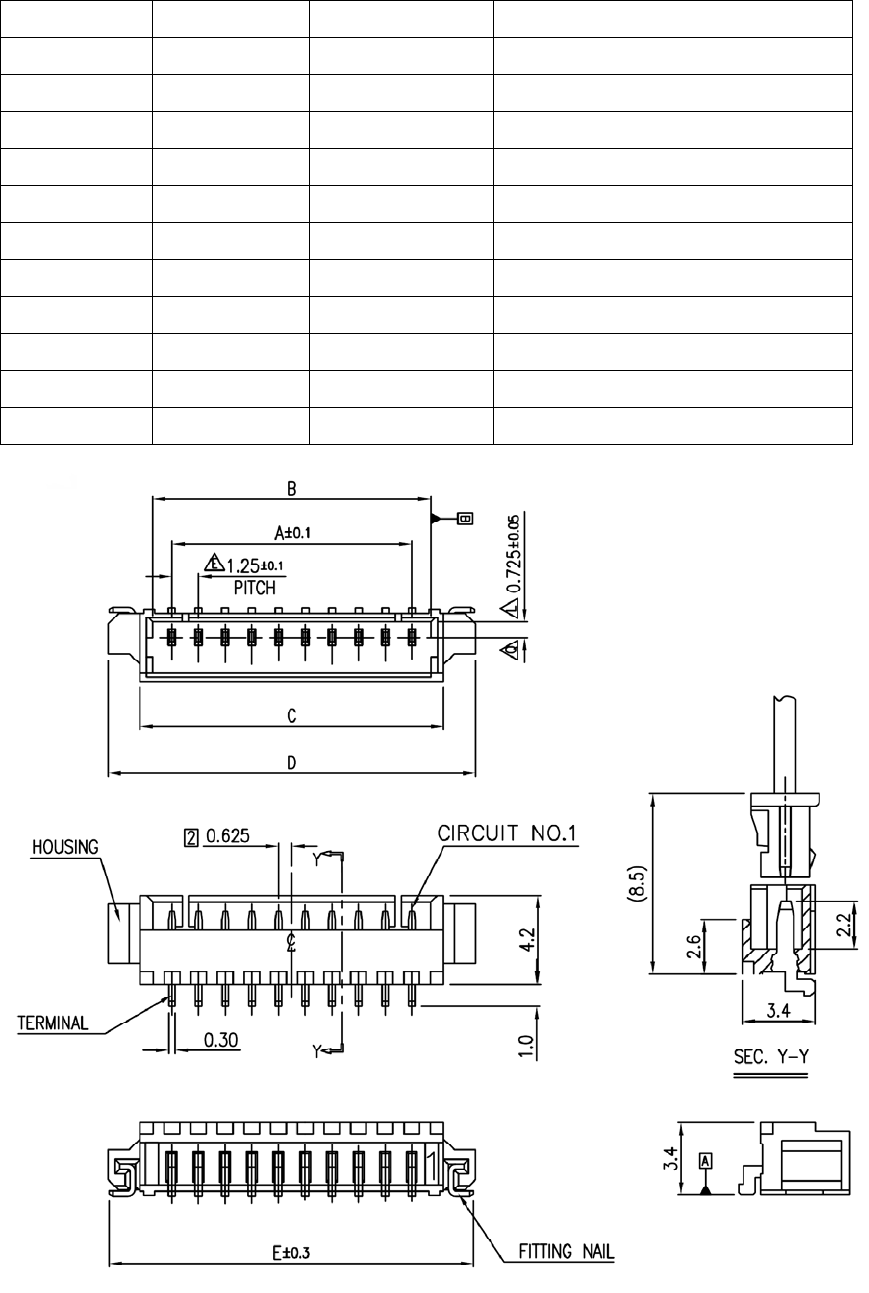
4.2 Digital/PowerConnectorDefinition
The digital connector provides power, serial communications signals, LED
signal and reset signals to the OR8400 module. These signals are provided
through a connector that is compatible with part number: Molex 53261-1571 -
1.25mm pin centers, 1 amp per pin rating which mates with Molex housing p/n
51021-1500 with crimps p/n 63811-0300.
DigitalConnectorSignalDefinition
PinNumberPinDefineSignalDirection Notes
1GNDPowerGround
Mustconnectbothpinstoground
2GNDPowerGround
3+12VDCPowerInputMustconnectbothpinstoDC+12V
8
4+12VDCPowerInput
5ANT0OutputAntennastatusbit0
6ANT1OutputAntennastatusbit1
7LED_CRCErrorOutputCommonAnode(330ohmonboard)
8LED_LinkOutputCommonAnode(330ohmonboard)
9UART_RXInput3.3VTTLLevel
10UART_TXOutput3.3VTTLLevel
11USB_DMBi‐directionalUSBDATA(D‐)Signal
12USB_DPBi‐directionalUSBDATA(D+)Signal
13USB_5V_SenseInputUSB5Vdetection
14N/A
15Reset_NInputLowReset(Moduleinternalpullhigh)
Connectordrawing

9
4.2.1 Antennastatussignals
The signals show antenna status currently. They also can be decoded for
LED usage.
Antennastatustable
Antenna ANT1 ANT0
Antenna1 0 0
Antenna2 0 1
Antenna3 1 0
Antenna4 1 1
4.2.2 LEDsignal
During an inventory command execution, two LEDs (LED_CRCError and
LED_Link) are used to indicate the tag read status. LED_Link is turned on
each time a valid EPC is received. LED_Link turns off when a tag is not read
(for any reason). Each time a CRC error in the EPC is detected,
LED_CRCError turns on. If no error is detected, LED_CRCError turns off.
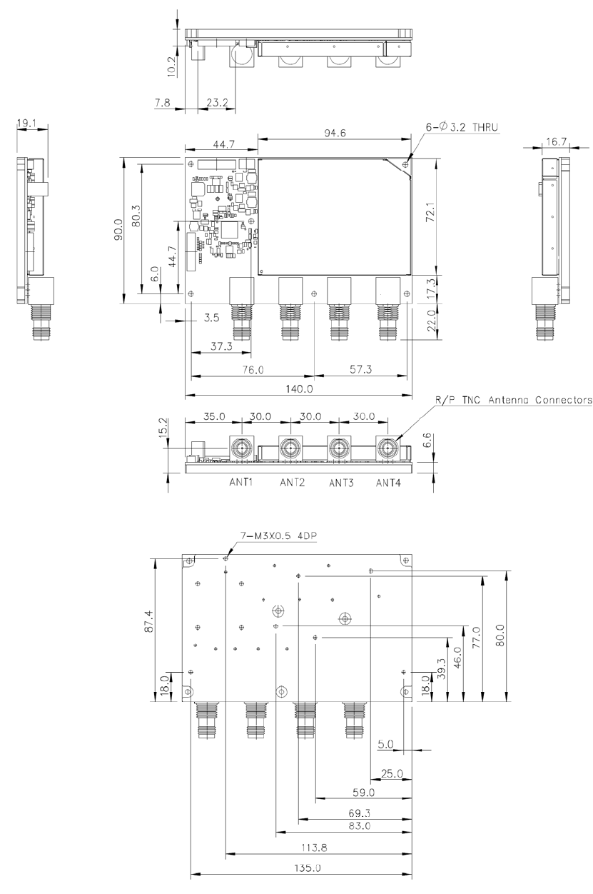
10
5 Mechanical Dimension