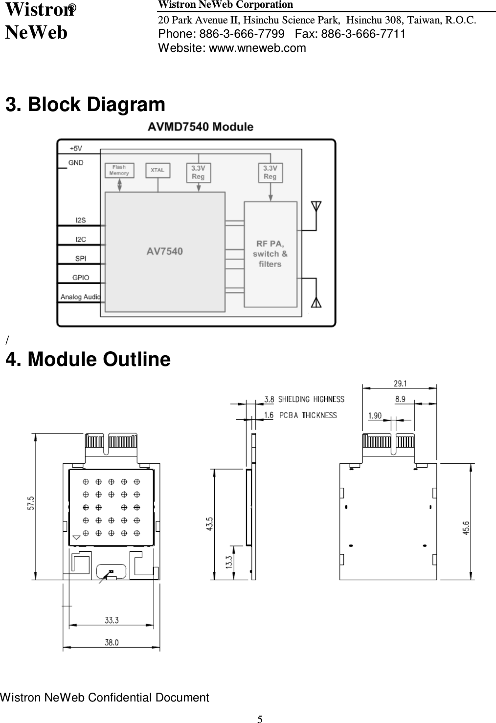
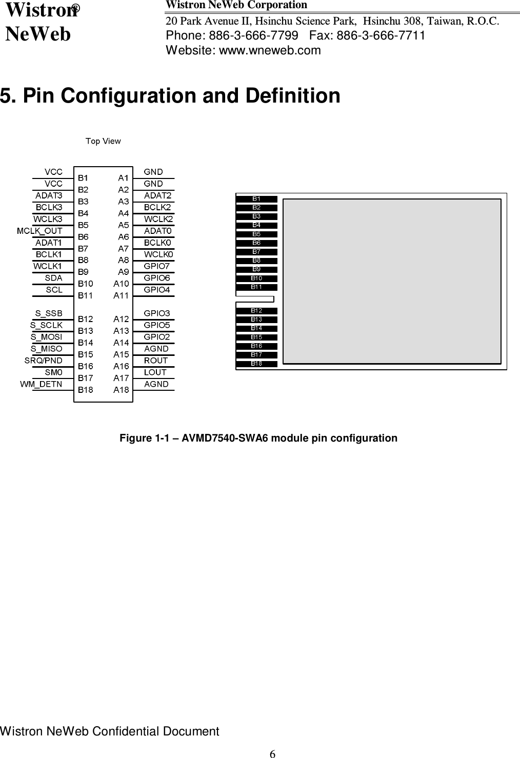
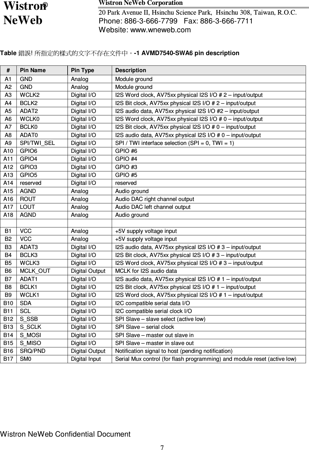
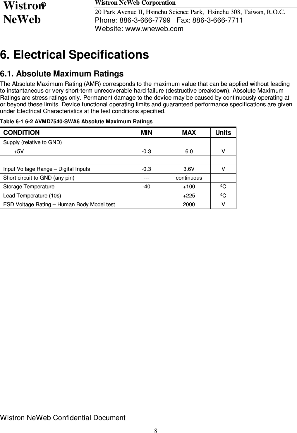
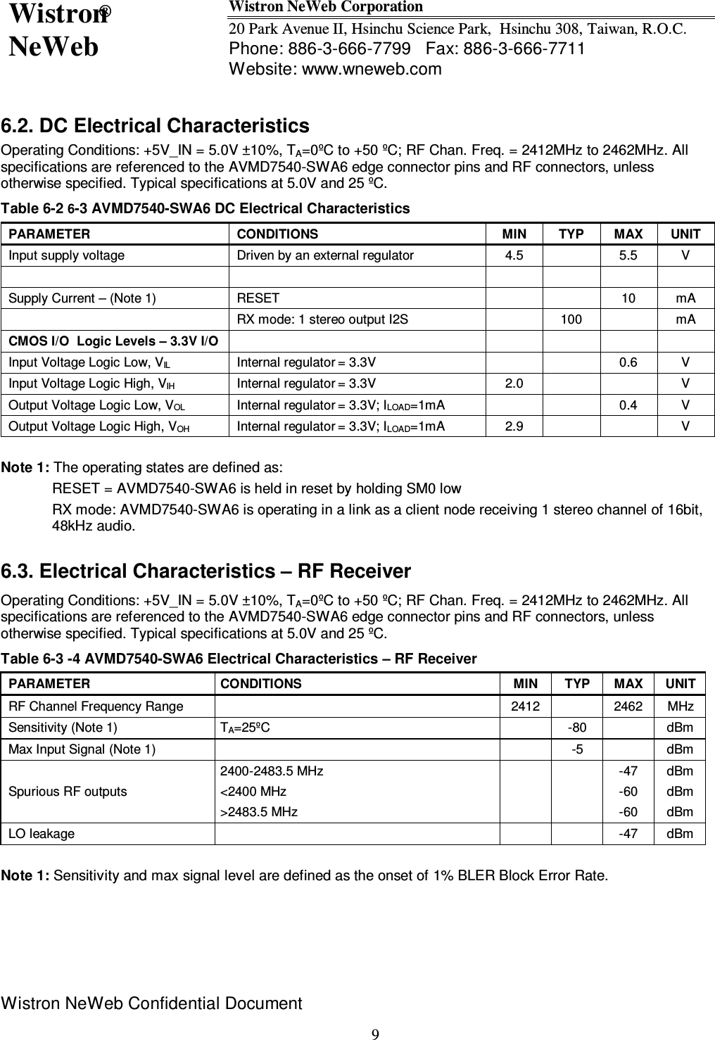
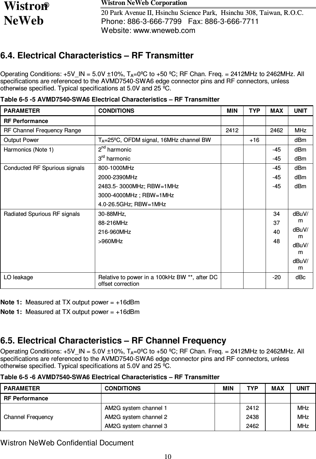
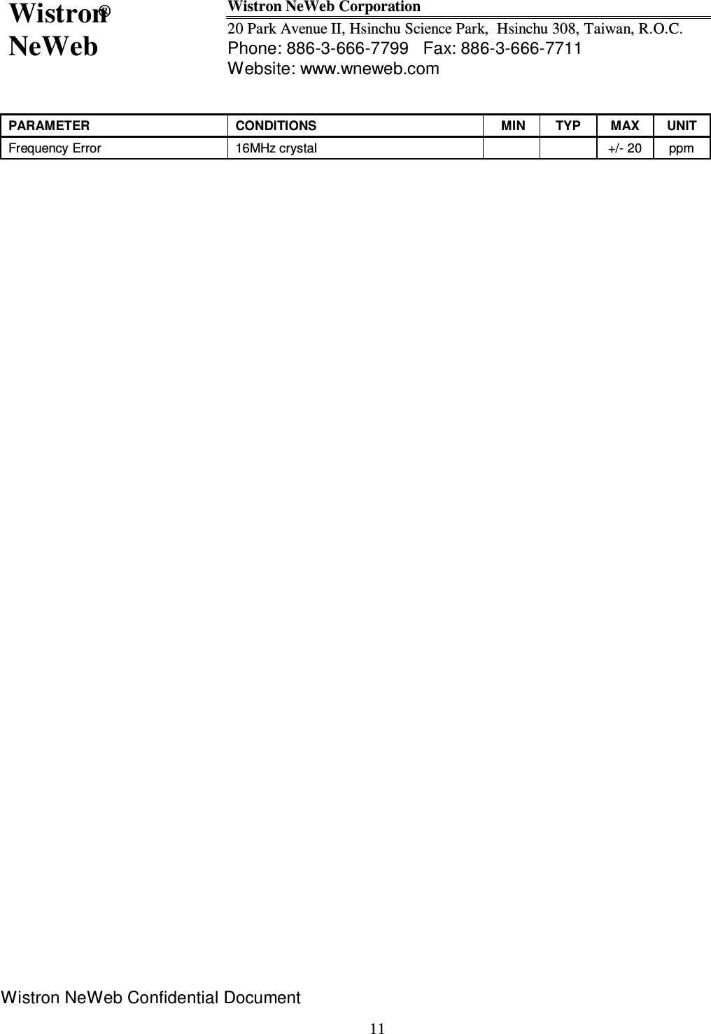
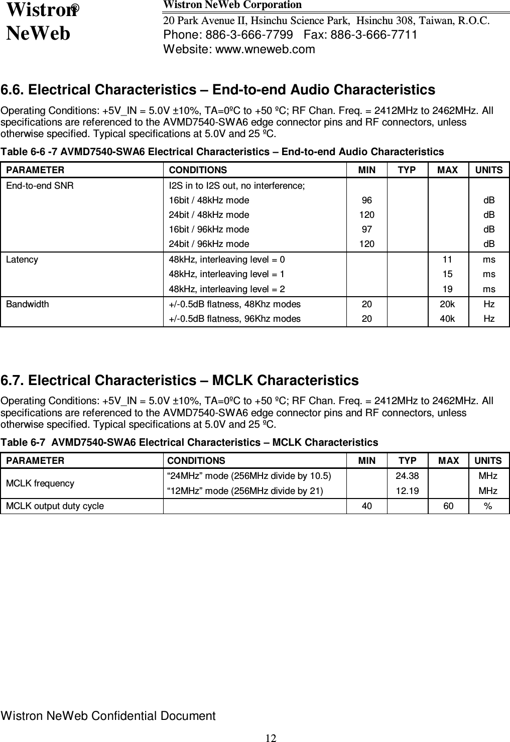
Wistron NeWeb SWA6 Wireless Audio Embedded Module User Manual AVMD7540 SWA6 datasheet 20100920

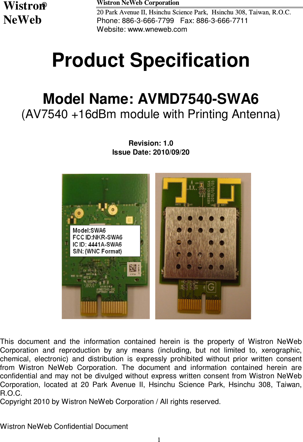
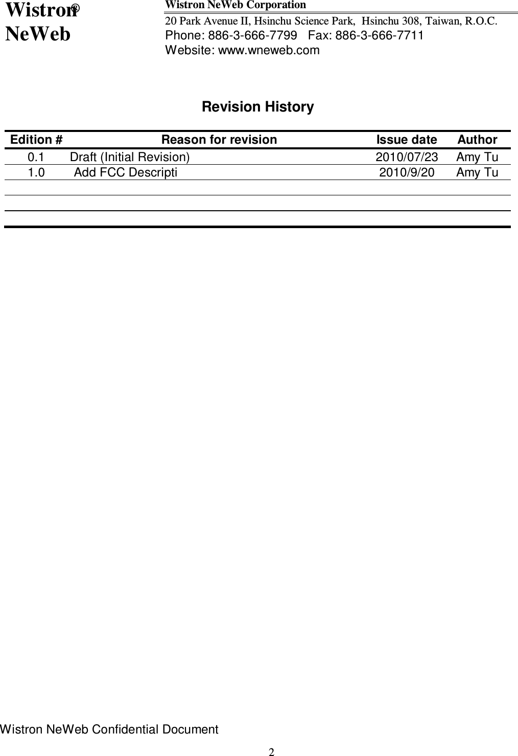
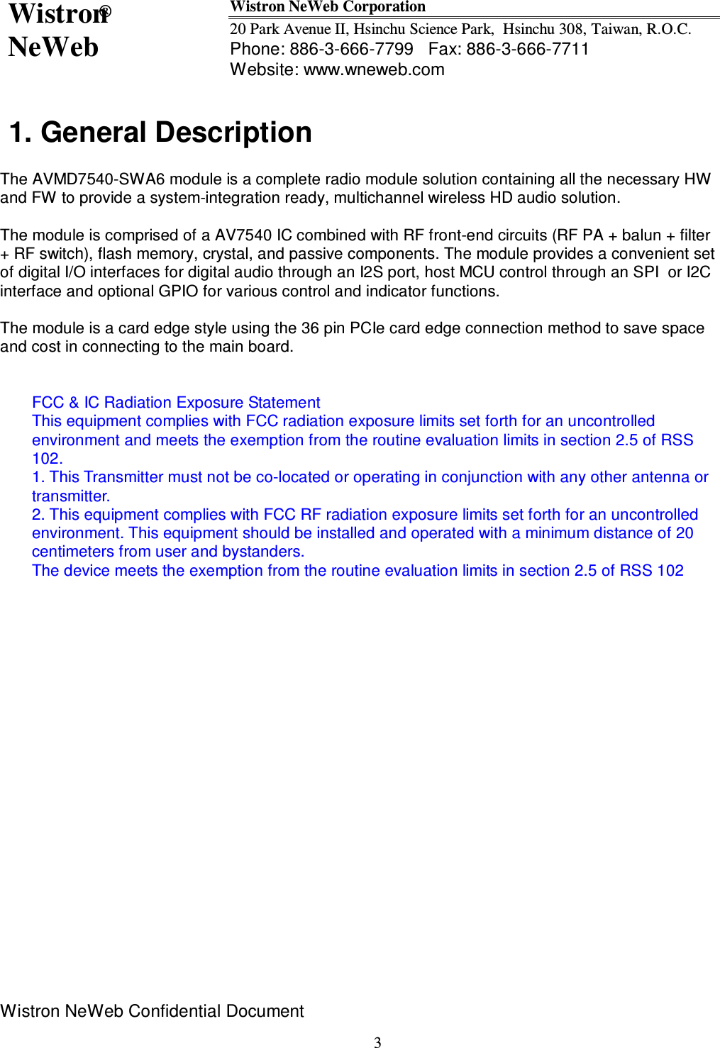
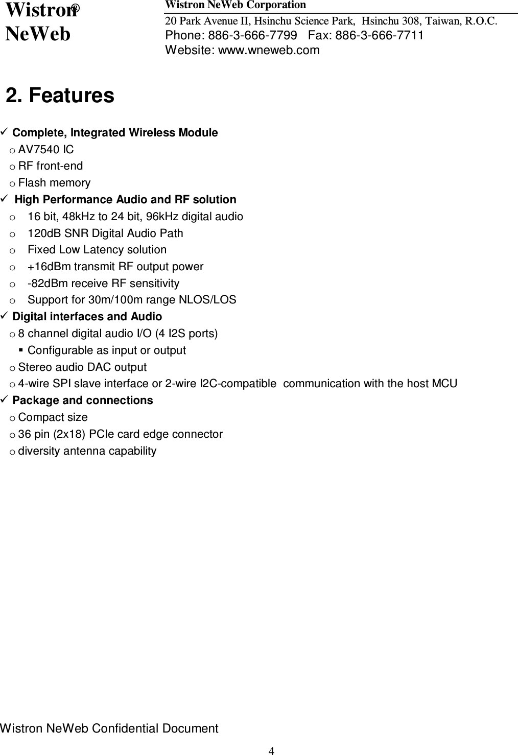
Wistron NeWeb Corporation Wireless Audio Embedded Module AVMD7540 SWA6 datasheet 20100920

Contents

User Manual

Wistron NeWeb® Wistron NeWeb Corporation 20 Park Avenue II, Hsinchu Science Park,  Hsinchu 308, Taiwan, R.O.C. Phone: 886-3-666-7799   Fax: 886-3-666-7711 Website: www.wneweb.com                 Wistron NeWeb Confidential Document    1Product Specification  Model Name: AVMD7540-SWA6 (AV7540 +16dBm module with Printing Antenna)   Revision: 1.0 Issue Date: 2010/09/20                 This  document  and  the  information  contained  herein  is  the  property  of  Wistron  NeWeb Corporation  and  reproduction  by  any  means  (including,  but  not  limited  to,  xerographic, chemical,  electronic)  and  distribution  is  expressly  prohibited  without  prior  written  consent from  Wistron  NeWeb  Corporation.  The  document  and  information  contained  herein  are confidential and may not be divulged without express written consent from Wistron NeWeb Corporation,  located  at  20  Park  Avenue  II,  Hsinchu  Science  Park,  Hsinchu  308,  Taiwan, R.O.C. Copyright 2010 by Wistron NeWeb Corporation / All rights reserved.
Wistron NeWeb® Wistron NeWeb Corporation 20 Park Avenue II, Hsinchu Science Park,  Hsinchu 308, Taiwan, R.O.C. Phone: 886-3-666-7799   Fax: 886-3-666-7711 Website: www.wneweb.com                 Wistron NeWeb Confidential Document    2 Revision History  Edition # Reason for revision  Issue date Author 0.1  Draft (Initial Revision) 2010/07/23 Amy Tu 1.0 Add FCC Descripti 2010/9/20 Amy Tu
Wistron NeWeb® Wistron NeWeb Corporation 20 Park Avenue II, Hsinchu Science Park,  Hsinchu 308, Taiwan, R.O.C. Phone: 886-3-666-7799   Fax: 886-3-666-7711 Website: www.wneweb.com                 Wistron NeWeb Confidential Document    31. General Description   The AVMD7540-SWA6 module is a complete radio module solution containing all the necessary HW and FW to provide a system-integration ready, multichannel wireless HD audio solution.    The module is comprised of a AV7540 IC combined with RF front-end circuits (RF PA + balun + filter + RF switch), flash memory, crystal, and passive components. The module provides a convenient set of digital I/O interfaces for digital audio through an I2S port, host MCU control through an SPI  or I2C interface and optional GPIO for various control and indicator functions.  The module is a card edge style using the 36 pin PCIe card edge connection method to save space and cost in connecting to the main board.   FCC & IC Radiation Exposure Statement This equipment complies with FCC radiation exposure limits set forth for an uncontrolled environment and meets the exemption from the routine evaluation limits in section 2.5 of RSS 102. 1. This Transmitter must not be co-located or operating in conjunction with any other antenna or transmitter. 2. This equipment complies with FCC RF radiation exposure limits set forth for an uncontrolled environment. This equipment should be installed and operated with a minimum distance of 20 centimeters from user and bystanders. The device meets the exemption from the routine evaluation limits in section 2.5 of RSS 102
Wistron NeWeb® Wistron NeWeb Corporation 20 Park Avenue II, Hsinchu Science Park,  Hsinchu 308, Taiwan, R.O.C. Phone: 886-3-666-7799   Fax: 886-3-666-7711 Website: www.wneweb.com                 Wistron NeWeb Confidential Document    42. Features   Complete, Integrated Wireless Module o AV7540 IC o RF front-end o Flash memory  High Performance Audio and RF solution o  16 bit, 48kHz to 24 bit, 96kHz digital audio  o  120dB SNR Digital Audio Path o  Fixed Low Latency solution o  +16dBm transmit RF output power  o  -82dBm receive RF sensitivity   o  Support for 30m/100m range NLOS/LOS  Digital interfaces and Audio o 8 channel digital audio I/O (4 I2S ports)  Configurable as input or output o Stereo audio DAC output o 4-wire SPI slave interface or 2-wire I2C-compatible  communication with the host MCU  Package and connections o Compact size o 36 pin (2x18) PCIe card edge connector o diversity antenna capability
Wistron NeWeb® Wistron NeWeb Corporation 20 Park Avenue II, Hsinchu Science Park,  Hsinchu 308, Taiwan, R.O.C. Phone: 886-3-666-7799   Fax: 886-3-666-7711 Website: www.wneweb.com                 Wistron NeWeb Confidential Document    5 3. Block Diagram            / 4. Module Outline
Wistron NeWeb® Wistron NeWeb Corporation 20 Park Avenue II, Hsinchu Science Park,  Hsinchu 308, Taiwan, R.O.C. Phone: 886-3-666-7799   Fax: 886-3-666-7711 Website: www.wneweb.com                 Wistron NeWeb Confidential Document    65. Pin Configuration and Definition     Figure 1-1 – AVMD7540-SWA6 module pin configuration
Wistron NeWeb® Wistron NeWeb Corporation 20 Park Avenue II, Hsinchu Science Park,  Hsinchu 308, Taiwan, R.O.C. Phone: 886-3-666-7799   Fax: 886-3-666-7711 Website: www.wneweb.com                 Wistron NeWeb Confidential Document    7Table ᙑᎄ! ࢬ ਐ ࡳ ऱ ᑌ ڤ ऱ ֮ ڗ լ ژ ڇ ֮ ٙ խ Ζ-1 AVMD7540-SWA6 pin description  #  Pin Name  Pin Type  Description A1 GND  Analog  Module ground A2 GND  Analog  Module ground A3 WCLK2  Digital I/O  I2S Word clock, AV75xx physical I2S I/O # 2 – input/output A4 BCLK2  Digital I/O  I2S Bit clock, AV75xx physical I2S I/O # 2 – input/output A5 ADAT2  Digital I/O  I2S audio data, AV75xx physical I2S I/O #2 – input/output A6 WCLK0  Digital I/O  I2S Word clock, AV75xx physical I2S I/O # 0 – input/output A7 BCLK0  Digital I/O  I2S Bit clock, AV75xx physical I2S I/O # 0 – input/output A8 ADAT0  Digital I/O  I2S audio data, AV75xx physical I2S I/O # 0 – input/output A9 SPI/TWI_SEL  Digital I/O  SPI / TWI interface selection (SPI = 0, TWI = 1) A10 GPIO6  Digital I/O  GPIO #6 A11 GPIO4  Digital I/O  GPIO #4 A12 GPIO3  Digital I/O  GPIO #3 A13 GPIO5  Digital I/O  GPIO #5 A14 reserved  Digital I/O  reserved A15 AGND  Analog  Audio ground A16 ROUT  Analog  Audio DAC right channel output A17 LOUT  Analog  Audio DAC left channel output A18 AGND  Analog  Audio ground        B1 VCC  Analog  +5V supply voltage input B2 VCC  Analog  +5V supply voltage input B3 ADAT3  Digital I/O  I2S audio data, AV75xx physical I2S I/O # 3 – input/output B4 BCLK3  Digital I/O  I2S Bit clock, AV75xx physical I2S I/O # 3 – input/output B5 WCLK3  Digital I/O  I2S Word clock, AV75xx physical I2S I/O # 3 – input/output B6 MCLK_OUT  Digital Output  MCLK for I2S audio data B7 ADAT1  Digital I/O  I2S audio data, AV75xx physical I2S I/O # 1 – input/output B8 BCLK1  Digital I/O  I2S Bit clock, AV75xx physical I2S I/O # 1 – input/output B9 WCLK1  Digital I/O  I2S Word clock, AV75xx physical I2S I/O # 1 – input/output B10 SDA  Digital I/O  I2C compatible serial data I/O B11 SCL  Digital I/O  I2C compatible serial clock I/O  B12 S_SSB  Digital I/O  SPI Slave – slave select (active low) B13 S_SCLK  Digital I/O  SPI Slave – serial clock B14 S_MOSI  Digital I/O  SPI Slave – master out slave in B15 S_MISO  Digital I/O  SPI Slave – master in slave out B16 SRQ/PND  Digital Output  Notification signal to host (pending notification) B17 SM0  Digital Input  Serial Mux control (for flash programming) and module reset (active low)
Wistron NeWeb® Wistron NeWeb Corporation 20 Park Avenue II, Hsinchu Science Park,  Hsinchu 308, Taiwan, R.O.C. Phone: 886-3-666-7799   Fax: 886-3-666-7711 Website: www.wneweb.com                 Wistron NeWeb Confidential Document    86. Electrical Specifications  6.1. Absolute Maximum Ratings The Absolute Maximum Rating (AMR) corresponds to the maximum value that can be applied without leading to instantaneous or very short-term unrecoverable hard failure (destructive breakdown). Absolute Maximum Ratings are stress ratings only. Permanent damage to the device may be caused by continuously operating at or beyond these limits. Device functional operating limits and guaranteed performance specifications are given under Electrical Characteristics at the test conditions specified. Table 6-1 6-2 AVMD7540-SWA6 Absolute Maximum Ratings CONDITION  MIN  MAX  Units Supply (relative to GND)         +5V  -0.3  6.0  V        Input Voltage Range – Digital Inputs  -0.3  3.6V   V Short circuit to GND (any pin)  ---  continuous   Storage Temperature  -40  +100  ºC Lead Temperature (10s)  --  +225  ºC ESD Voltage Rating – Human Body Model test    2000  V
Wistron NeWeb® Wistron NeWeb Corporation 20 Park Avenue II, Hsinchu Science Park,  Hsinchu 308, Taiwan, R.O.C. Phone: 886-3-666-7799   Fax: 886-3-666-7711 Website: www.wneweb.com                 Wistron NeWeb Confidential Document    96.2. DC Electrical Characteristics Operating Conditions: +5V_IN = 5.0V ±10%, TA=0ºC to +50 ºC; RF Chan. Freq. = 2412MHz to 2462MHz. All specifications are referenced to the AVMD7540-SWA6 edge connector pins and RF connectors, unless otherwise specified. Typical specifications at 5.0V and 25 ºC. Table 6-2 6-3 AVMD7540-SWA6 DC Electrical Characteristics PARAMETER  CONDITIONS  MIN  TYP  MAX  UNIT Input supply voltage  Driven by an external regulator  4.5    5.5  V            Supply Current – (Note 1)  RESET       10  mA   RX mode: 1 stereo output I2S    100    mA CMOS I/O  Logic Levels – 3.3V I/O          Input Voltage Logic Low, VIL  Internal regulator = 3.3V      0.6  V Input Voltage Logic High, VIH  Internal regulator = 3.3V  2.0      V Output Voltage Logic Low, VOL  Internal regulator = 3.3V; ILOAD=1mA      0.4  V Output Voltage Logic High, VOH  Internal regulator = 3.3V; ILOAD=1mA  2.9      V  Note 1: The operating states are defined as:   RESET = AVMD7540-SWA6 is held in reset by holding SM0 low   RX mode: AVMD7540-SWA6 is operating in a link as a client node receiving 1 stereo channel of 16bit, 48kHz audio.  6.3. Electrical Characteristics – RF Receiver Operating Conditions: +5V_IN = 5.0V ±10%, TA=0ºC to +50 ºC; RF Chan. Freq. = 2412MHz to 2462MHz. All specifications are referenced to the AVMD7540-SWA6 edge connector pins and RF connectors, unless otherwise specified. Typical specifications at 5.0V and 25 ºC. Table 6-3 -4 AVMD7540-SWA6 Electrical Characteristics – RF Receiver PARAMETER  CONDITIONS  MIN  TYP MAX UNIT RF Channel Frequency Range    2412   2462 MHz Sensitivity (Note 1)   TA=25ºC     -80    dBm Max Input Signal (Note 1)      -5    dBm Spurious RF outputs 2400-2483.5 MHz <2400 MHz >2483.5 MHz    -47 -60 -60 dBm dBm dBm LO leakage        -47  dBm  Note 1: Sensitivity and max signal level are defined as the onset of 1% BLER Block Error Rate.
Wistron NeWeb® Wistron NeWeb Corporation 20 Park Avenue II, Hsinchu Science Park,  Hsinchu 308, Taiwan, R.O.C. Phone: 886-3-666-7799   Fax: 886-3-666-7711 Website: www.wneweb.com                 Wistron NeWeb Confidential Document    106.4. Electrical Characteristics – RF Transmitter  Operating Conditions: +5V_IN = 5.0V ±10%, TA=0ºC to +50 ºC; RF Chan. Freq. = 2412MHz to 2462MHz. All specifications are referenced to the AVMD7540-SWA6 edge connector pins and RF connectors, unless otherwise specified. Typical specifications at 5.0V and 25 ºC. Table 6-5 -5 AVMD7540-SWA6 Electrical Characteristics – RF Transmitter PARAMETER  CONDITIONS  MIN  TYP  MAX UNIT RF Performance           RF Channel Frequency Range    2412   2462 MHz Output Power   TA=25ºC, OFDM signal, 16MHz channel BW    +16    dBm Harmonics (Note 1)  2nd harmonic 3rd harmonic     -45 -45 dBm dBm Conducted RF Spurious signals  800-1000MHz 2000-2390MHz 2483.5- 3000MHz; RBW=1MHz 3000-4000MHz ; RBW=1MHz 4.0-26.5GHz; RBW=1MHz     -45 -45 -45 dBm dBm dBm Radiated Spurious RF signals  30-88MHz, 88-216MHz 216-960MHz >960MHz   34 37 40 48 dBuV/m dBuV/m dBuV/m dBuV/m LO leakage  Relative to power in a 100kHz BW **, after DC offset correction      -20  dBc  Note 1:  Measured at TX output power = +16dBm Note 1:  Measured at TX output power = +16dBm   6.5. Electrical Characteristics – RF Channel Frequency Operating Conditions: +5V_IN = 5.0V ±10%, TA=0ºC to +50 ºC; RF Chan. Freq. = 2412MHz to 2462MHz. All specifications are referenced to the AVMD7540-SWA6 edge connector pins and RF connectors, unless otherwise specified. Typical specifications at 5.0V and 25 ºC. Table 6-5 -6 AVMD7540-SWA6 Electrical Characteristics – RF Transmitter PARAMETER  CONDITIONS  MIN  TYP  MAX  UNIT RF Performance           Channel Frequency  AM2G system channel 1 AM2G system channel 2 AM2G system channel 3  2412 2438 2462  MHz MHz MHz
Wistron NeWeb® Wistron NeWeb Corporation 20 Park Avenue II, Hsinchu Science Park,  Hsinchu 308, Taiwan, R.O.C. Phone: 886-3-666-7799   Fax: 886-3-666-7711 Website: www.wneweb.com                 Wistron NeWeb Confidential Document    11PARAMETER  CONDITIONS  MIN  TYP  MAX  UNIT Frequency Error  16MHz crystal    +/- 20 ppm
Wistron NeWeb® Wistron NeWeb Corporation 20 Park Avenue II, Hsinchu Science Park,  Hsinchu 308, Taiwan, R.O.C. Phone: 886-3-666-7799   Fax: 886-3-666-7711 Website: www.wneweb.com                 Wistron NeWeb Confidential Document    126.6. Electrical Characteristics – End-to-end Audio Characteristics Operating Conditions: +5V_IN = 5.0V ±10%, TA=0ºC to +50 ºC; RF Chan. Freq. = 2412MHz to 2462MHz. All specifications are referenced to the AVMD7540-SWA6 edge connector pins and RF connectors, unless otherwise specified. Typical specifications at 5.0V and 25 ºC. Table 6-6 -7 AVMD7540-SWA6 Electrical Characteristics – End-to-end Audio Characteristics PARAMETER  CONDITIONS  MIN  TYP  MAX  UNITS End-to-end SNR  I2S in to I2S out, no interference;  16bit / 48kHz mode 24bit / 48kHz mode 16bit / 96kHz mode 24bit / 96kHz mode  96 120 97 120      dB dB dB dB Latency  48kHz, interleaving level = 0 48kHz, interleaving level = 1 48kHz, interleaving level = 2     11 15 19 ms ms ms Bandwidth  +/-0.5dB flatness, 48Khz modes +/-0.5dB flatness, 96Khz modes 20 20   20k 40k Hz Hz    6.7. Electrical Characteristics – MCLK Characteristics Operating Conditions: +5V_IN = 5.0V ±10%, TA=0ºC to +50 ºC; RF Chan. Freq. = 2412MHz to 2462MHz. All specifications are referenced to the AVMD7540-SWA6 edge connector pins and RF connectors, unless otherwise specified. Typical specifications at 5.0V and 25 ºC. Table 6-7  AVMD7540-SWA6 Electrical Characteristics – MCLK Characteristics PARAMETER  CONDITIONS  MIN  TYP  MAX  UNITS MCLK frequency  “24MHz” mode (256MHz divide by 10.5) “12MHz” mode (256MHz divide by 21)   24.38 12.19  MHz MHz MCLK output duty cycle    40    60  %
Wistron NeWeb® Wistron NeWeb Corporation 20 Park Avenue II, Hsinchu Science Park,  Hsinchu 308, Taiwan, R.O.C. Phone: 886-3-666-7799   Fax: 886-3-666-7711 Website: www.wneweb.com                 Wistron NeWeb Confidential Document    137. Package Information

Navigation menu