Wistron NeWeb WLD71-T3A LTE Router User Manual
Wistron NeWeb Corporation LTE Router
UserManual.wiki
>
Wistron NeWeb
>
WLD71 T3A User Manual
User manual
Navigation menu
Upload a User Manual
Namespaces
Wiki Guide
HTML
PDF
Info
Views
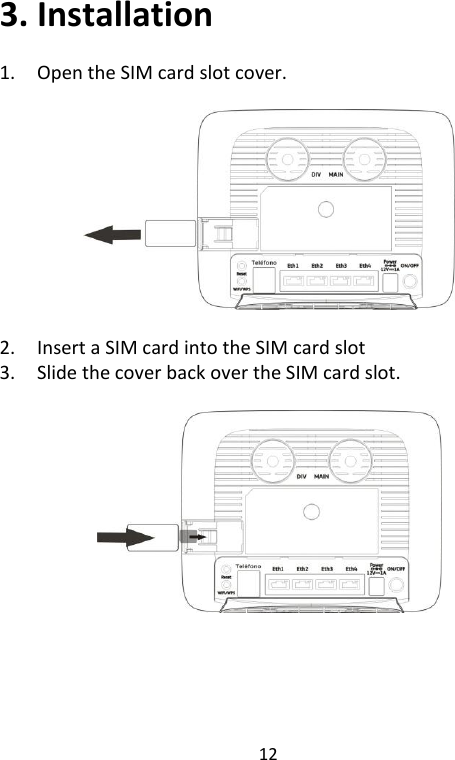
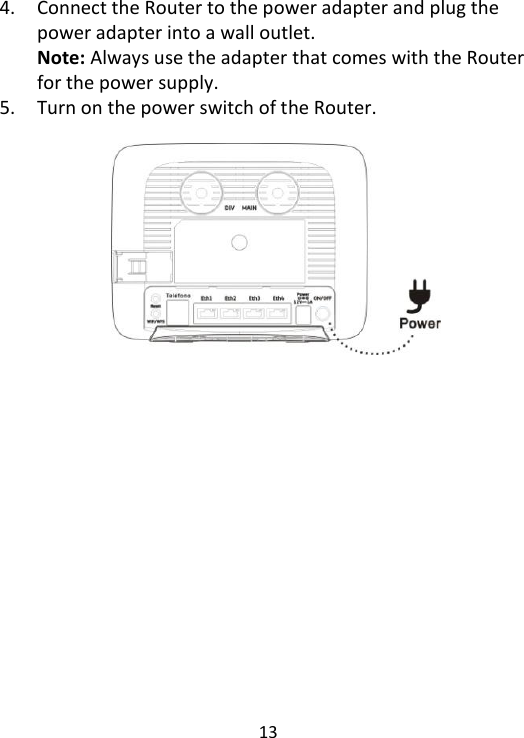
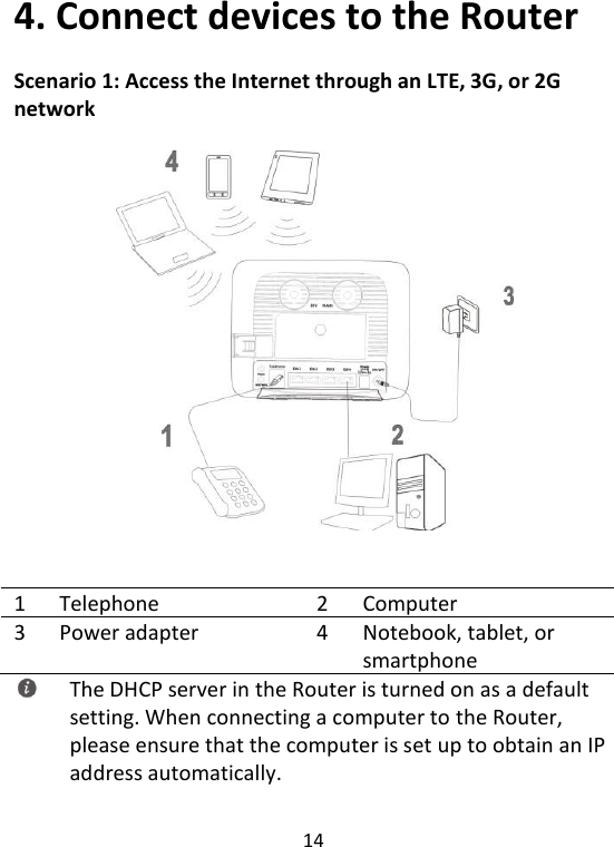
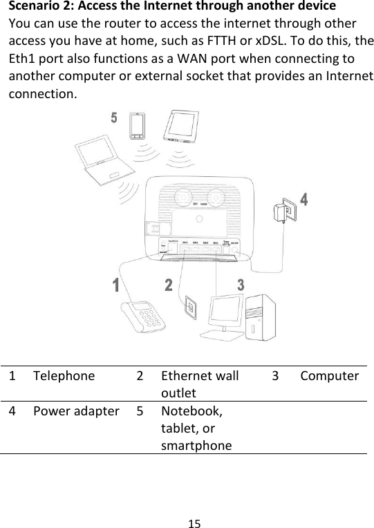
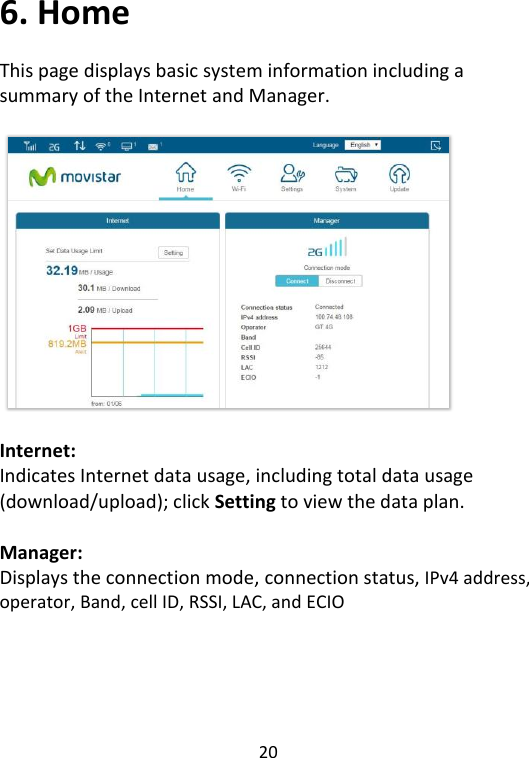
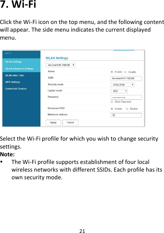
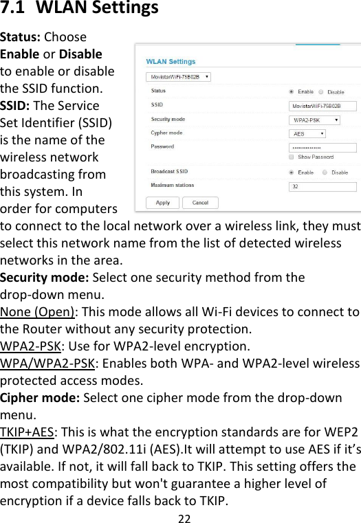
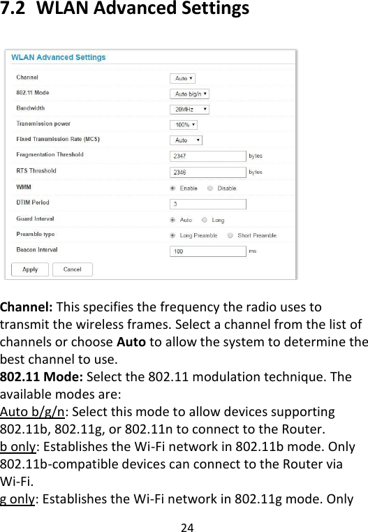
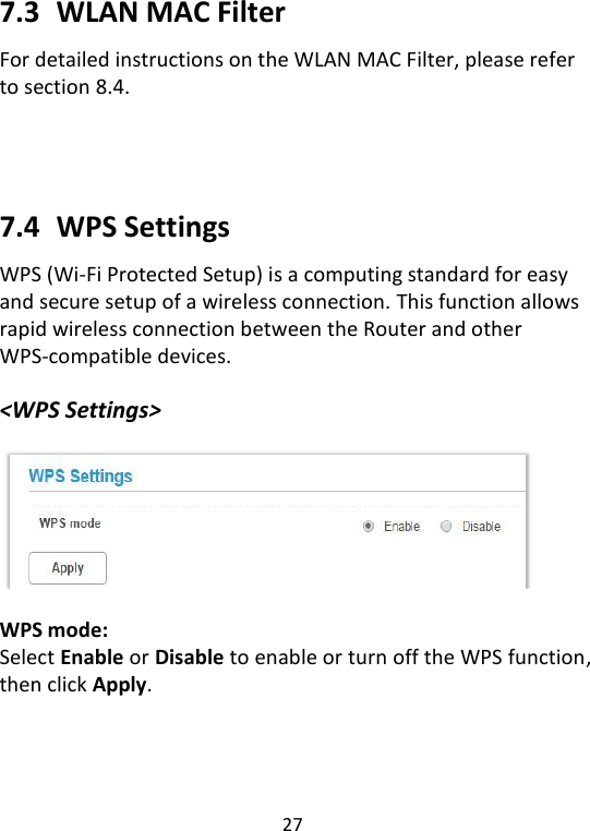
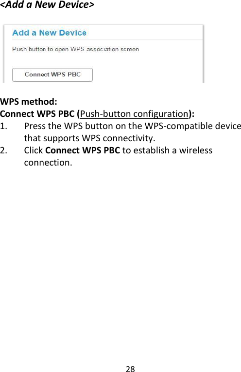
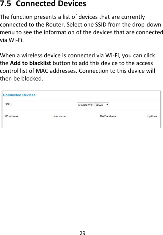
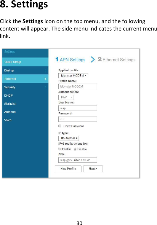
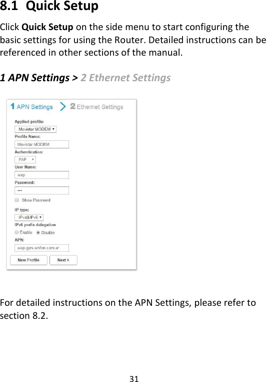
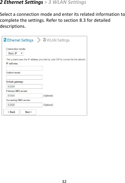
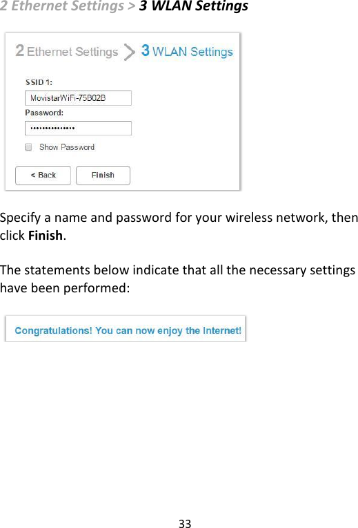
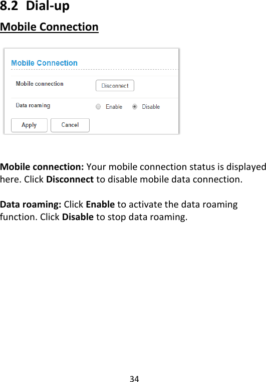
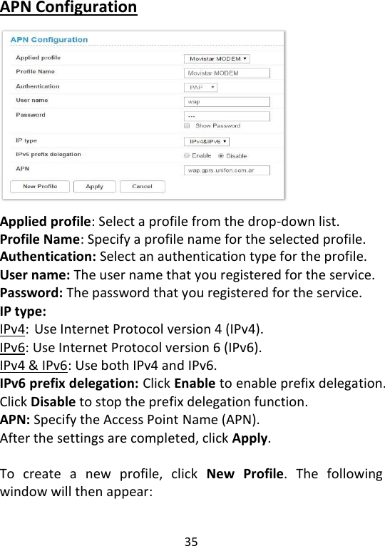
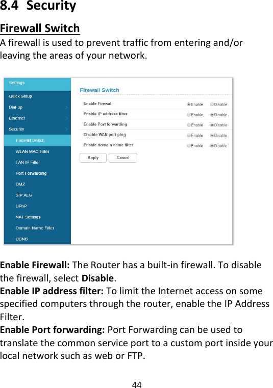
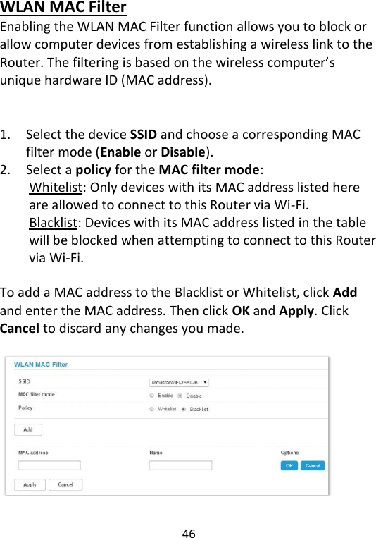
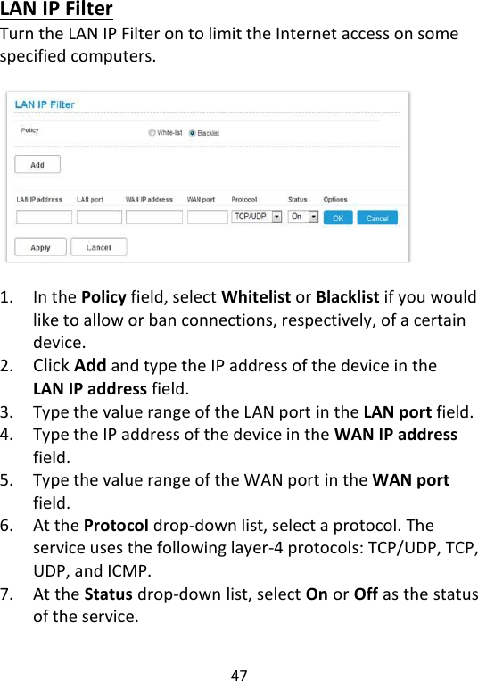
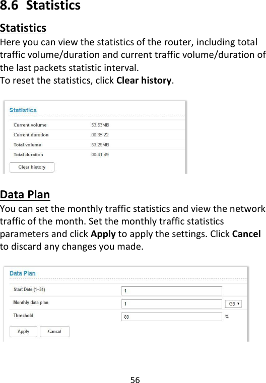
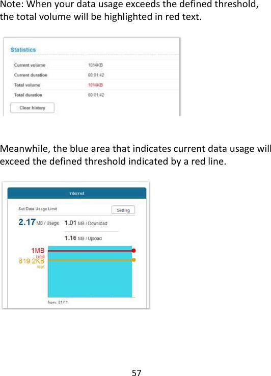
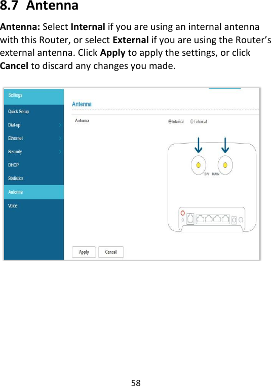
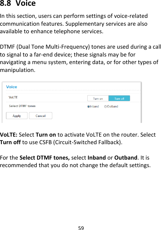
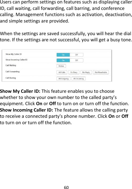
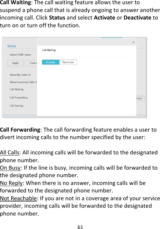
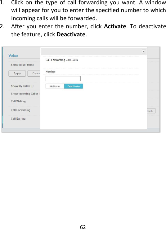
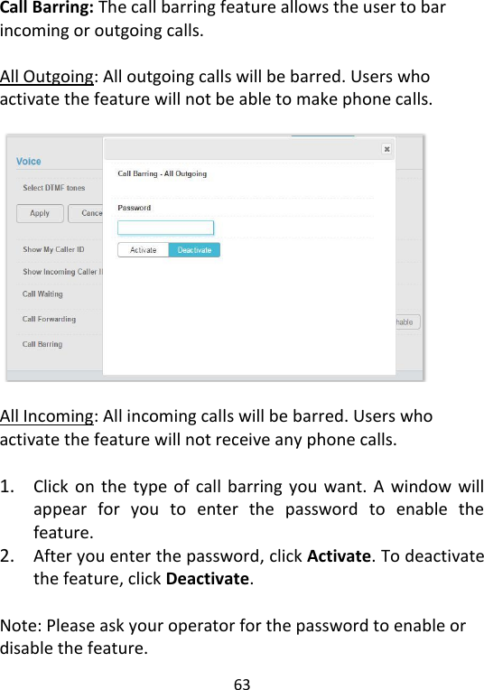
User Manual
Discussion / Help
Navigation