Woori Technology AVR445 AV RECEIVER User Manual AVR 445 OM
Woori Technology Inc AV RECEIVER AVR 445 OM
UserManual.wiki
>
Woori Technology
>
AVR445 User Manual
USERS MANUAL
Navigation menu
Upload a User Manual
Namespaces
Wiki Guide
HTML
PDF
Info
Views
User Manual
Discussion / Help
Navigation
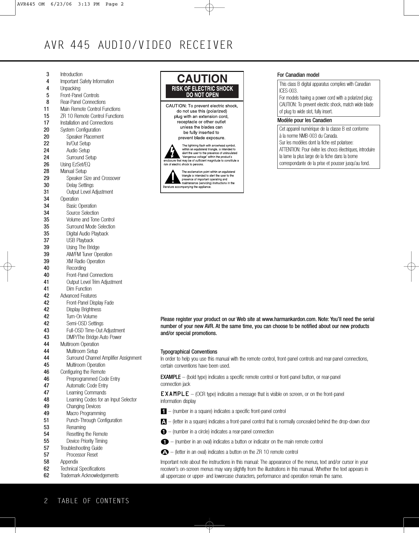
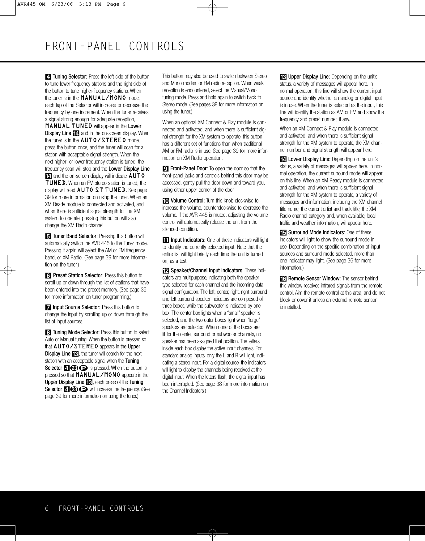
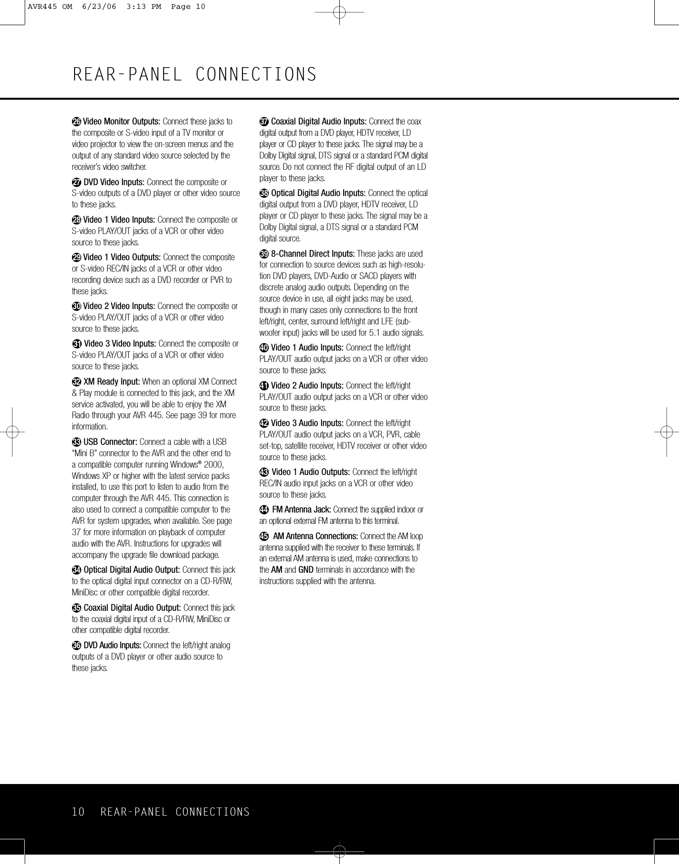

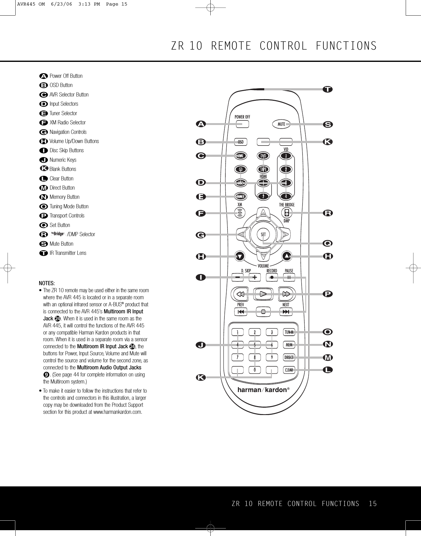
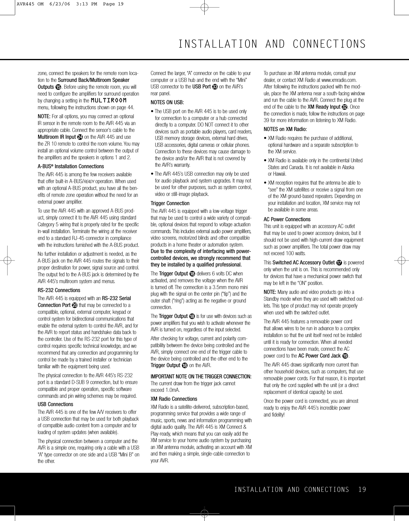
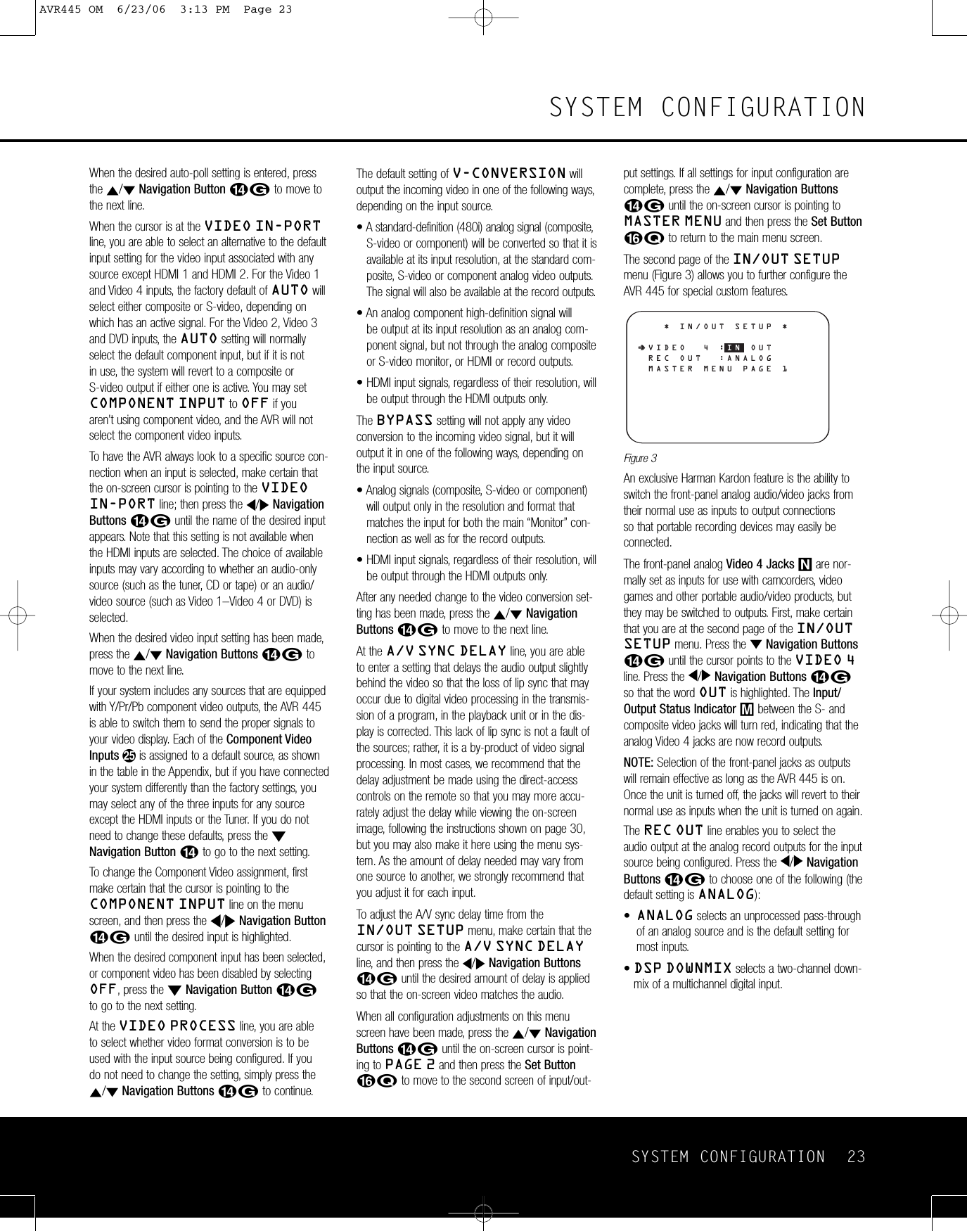
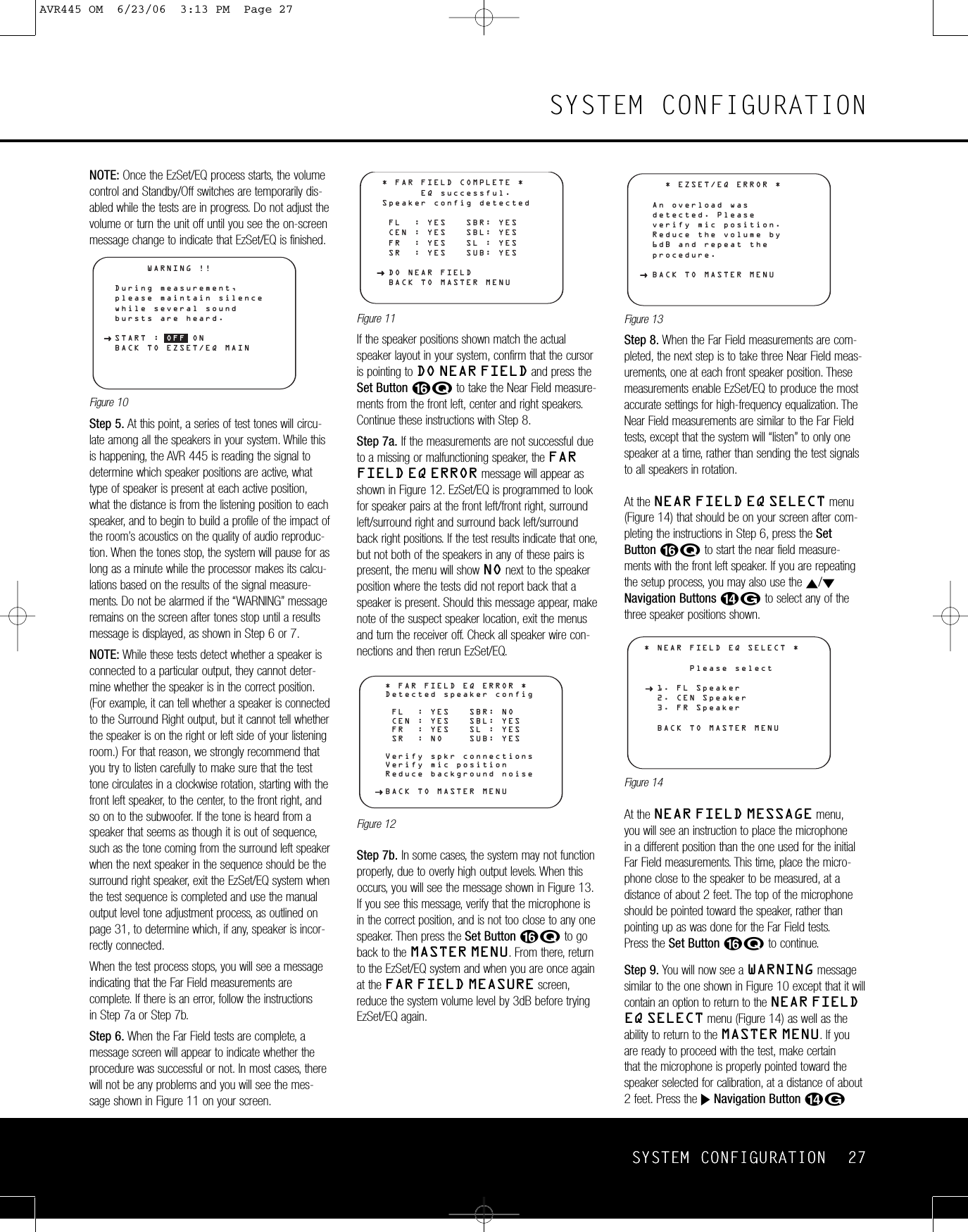
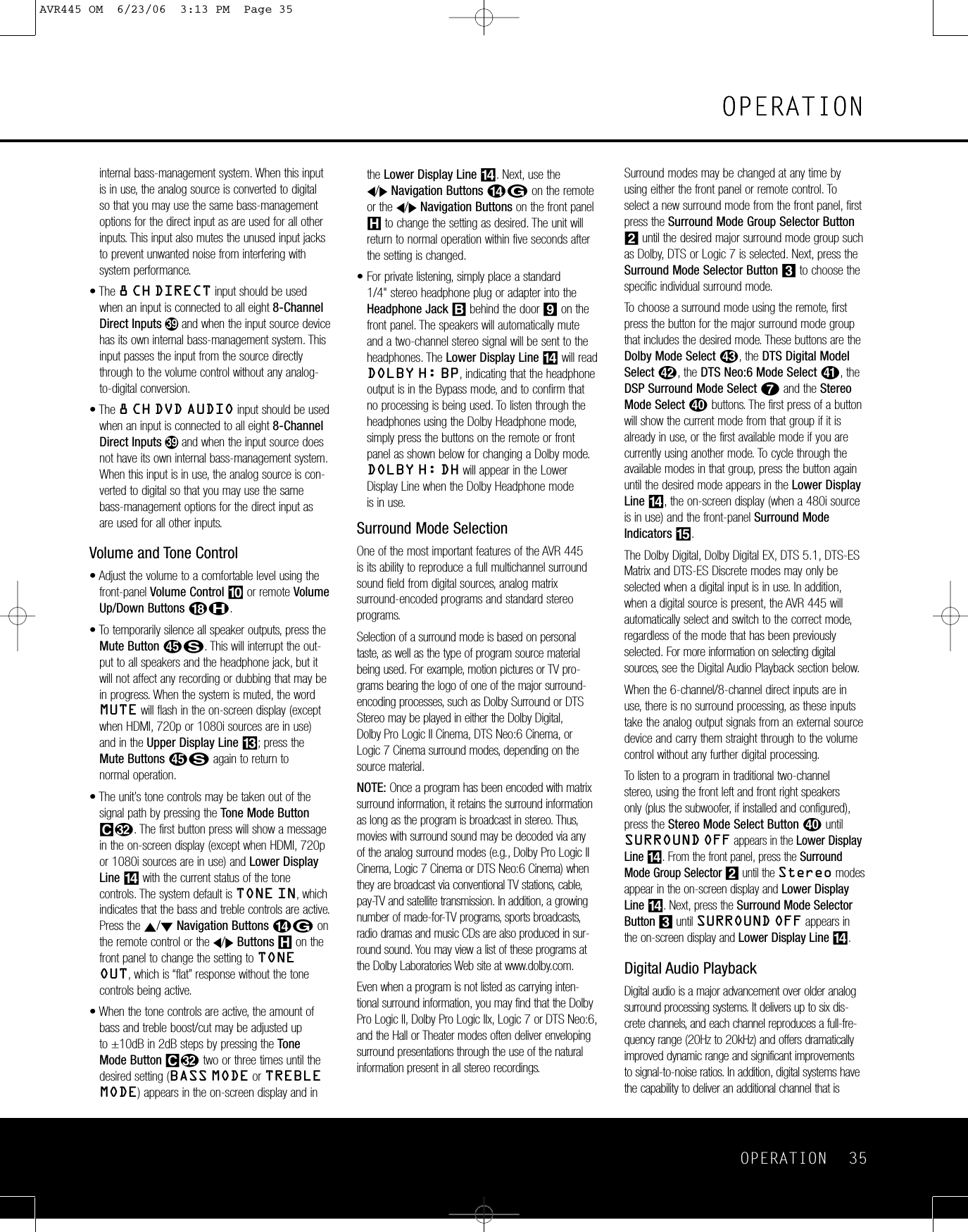
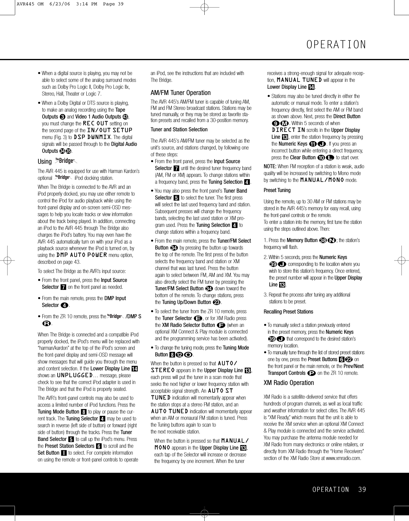
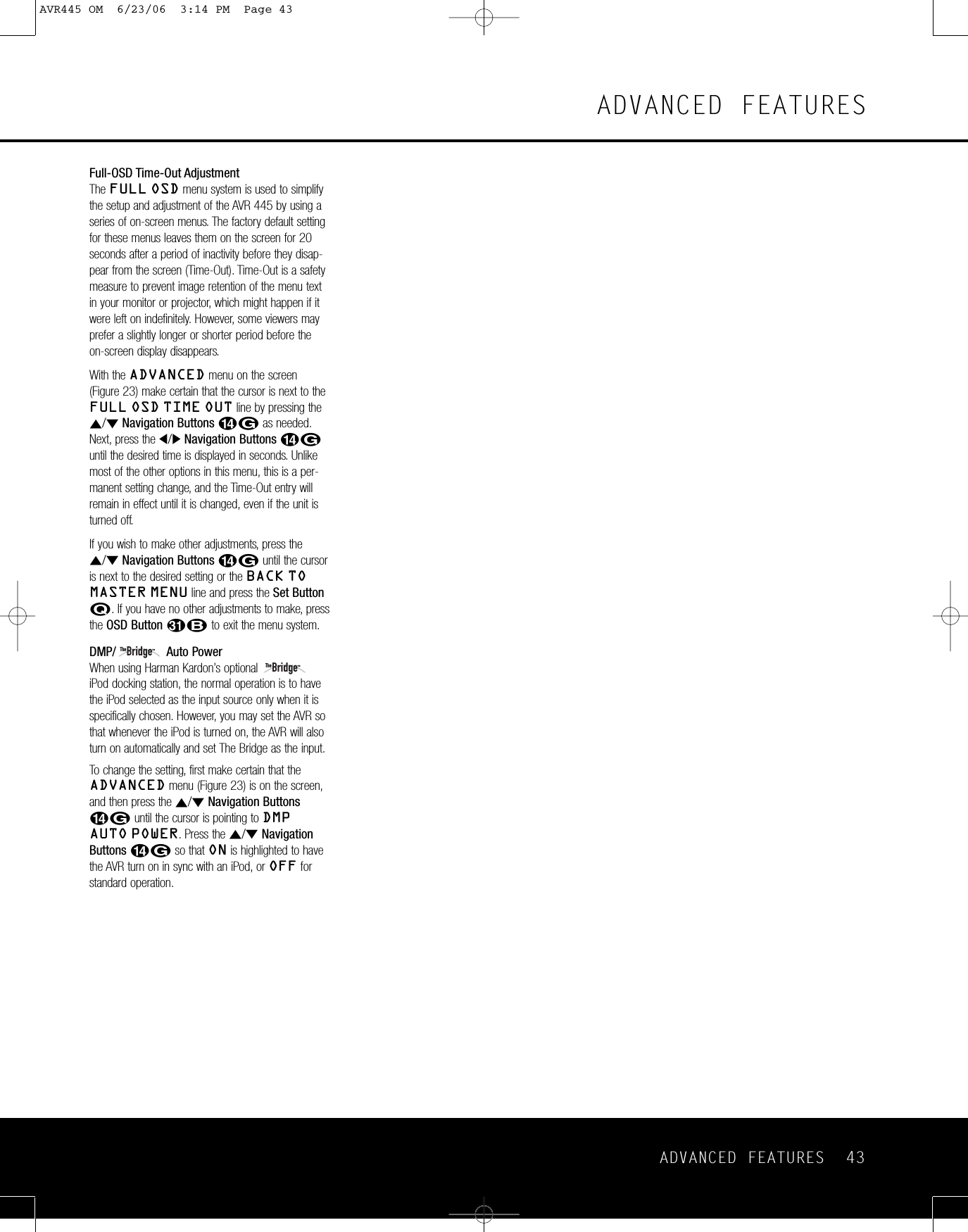
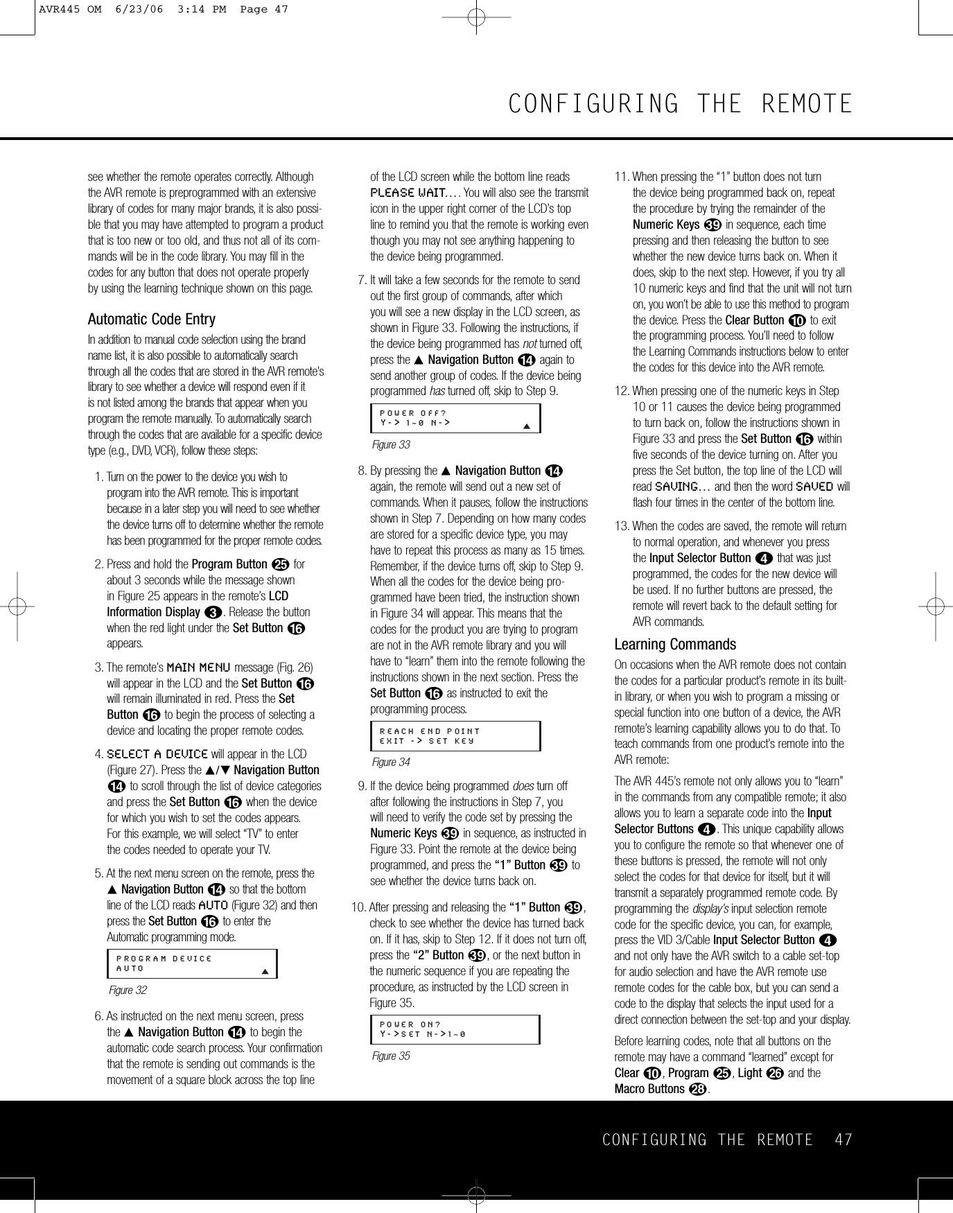
![50 CONFIGURING THE REMOTECONFIGURING THE REMOTERecording a MacroTo record a macro into the remote’s memory, followthese steps:1. Press and hold the Program Buttonyforabout three seconds while the message shown in Figure 25 appears in the remote’s LCDInformation Display2.Release the buttonwhen the red light under the Set Button Fappears.2. The remote’s MAIN MENU message (Figure26), will appear in the LCD and the Set ButtonFwill remain illuminated in red. Press the ⁄Navigation Button Dso that MACROappears on the bottom line of the LCD, as shownin Figure 48. Press the Set Button Fto enterthe main macro menu branch.Figure 483. At the next menu screen (Figure 49) press the Set Button Fto begin recording a macro.Figure 494. The next display screen (Figure 50) is where youselect the button that will be used to recall themacro. The choices are the Power On Button1or one of the discrete Macro ButtonsR.Press the ⁄/¤Navigation Button Duntil the name of the button you wish to program themacro into is shown. For this example we willshow how to program a series of commands thatwill automatically be sent out every time thePower button is pressed.Figure 505. The next screen that appears (Figure 51) is whereyou select the device for the first command thatwill be sent out as part of the macro. Press the⁄/¤Navigation Button Duntil the name ofthe device appears on the left side of the lowerline in the LCD. For this example, the first buttonwe want to have the macro “press” is the PowerOn button, so the AVR device is selected. Press theSet Button Fwhen the desired device nameappears to move to the next programming step.Figure 516. The next display (Figure 52) is where you beginentering the individual commands for the macro,in the order you wish them to be transmitted.Remember that when you want to change devices,you must first press the Input Selectors dfor that button, and then press the Command orFunction key. Since we want to program a series of events that occur each time the Power On button is pressed, press the AVR button. In yourspecific macro, this is the first command button.Figure 527. The next display (Figure 53) and the subsequentscreens are where the actual macro programmingtakes place. The words at the left side of the topline of the display show the button that is beingprogrammed (e.g., the Power On Button1orone of the Macro Buttons R)and the indica-tion at the right side of the top line shows thenumber of macro steps available of 20 possiblesteps. Following the instructions on the remote’sLCD screen, press the first key you wish to betransmitted in the macro. In our example, we firstwant the AVR 445 to turn on, so the PowerButton1should be pressed.Figure 538. Once the first command button for the macro hasbeen pressed, continue to press the buttons youwish to be part of the macro, in the order they willbe used. Press each button within five seconds of the last button, remembering to press theInput Selector3when you are changingdevice functions. As the buttons on the remote are pressed,the remote’s display screen will show the steps in the macro as they are programmed (Figure 54).Figure 549. For our example, we first want the AVR Power On button pressed, followed by the TV Power On,followed by the Cable Box On, followed by theselection of the Logic 7 mode. To do that, pressthe buttons in this order:•Power On1•VID 2/TV3•Power On1•VID 3/Cable3•Power On1•AVR4•Logic 7hAs each button is pressed to enter it into themacro, you will see the button names appear andthen scroll up on the LCD as your confirmation ofthe key entry (Figure 54).10. When all commands for the macro have beenentered, press the Set Button Fto save themacro. The display screen will show the button to which the macro has been programmed andthe number of steps used, and the word SAVEDwill blink four times in the lower line of the LCD.When the display returns to normal, the macrohas been entered and the remote is ready foroperation.11. If a macro has been programmed into the PowerOn Button1, it will play back anytime thePower On button is pressed. As the macro plays,you will see the steps appear in the remote’s LCD.Macros programmed into one of the four discreteMacro buttons may be activated at any time bypressing the appropriate button.Erasing a MacroOnce a macro has been created and stored in theAVR remote’s memory, you have the option of erasing it. You may do this at any time by followingthese steps:1. Press and hold the Program ButtonOforabout three seconds while the message shown in Figure 25 appears in the remote’sLCDInformation Display2. Release the buttonwhen the red light under the Set Button Fappears.2. The remote’sMAIN MENU message (Figure26), will appear in the LCD and the Set ButtonFwill remain illuminated in red. Press the ⁄Navigation Button Dso that MACROappears on the bottom line of the LCD screen, asshown in Figure 48. Press the Set Button Ftoenter the main macro menu branch.3. At the next menu screen (Figure 55), press the⁄/¤Navigation Button Duntil the bottomline in the remote’sLCD reads ERASE A MACRO.Press the Set Button Fto begin the processof erasing a macro.Figure 554. The next display screen (Figure 56) is where youselect which macro will be erased. Press the⁄/¤Navigation Button Duntil the numberof the macro you wish to erase appears. For this example, we will erase the Power On macrocreated in the previous section. When the nameMACROERASE A MACRO[AVR][AVR] POWER ONPOWER ON 00/20SELECT KEY PRESSSELECT A DEVICEAVRSELECT A DEVICEAVRRECORD A MACROPOWER ONMACRORECORD A MACROMAIN MENUMACROAVR445 OM 6/23/06 3:14 PM Page 50](https://usermanual.wiki/Woori-Technology/AVR445/User-Guide-683107-Page-50.png)
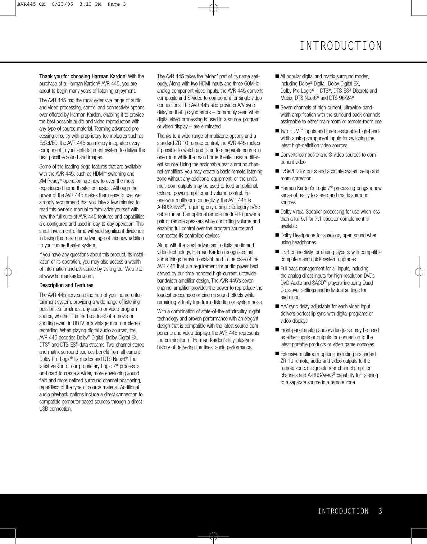
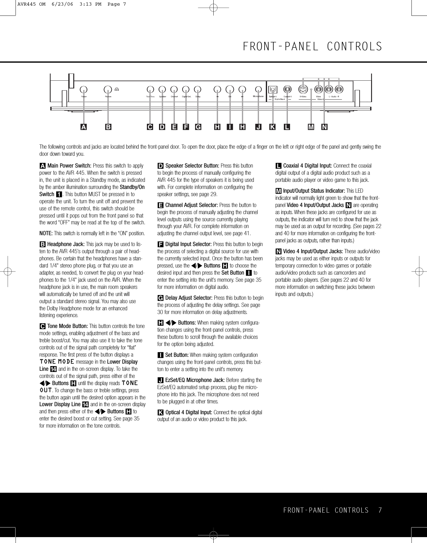
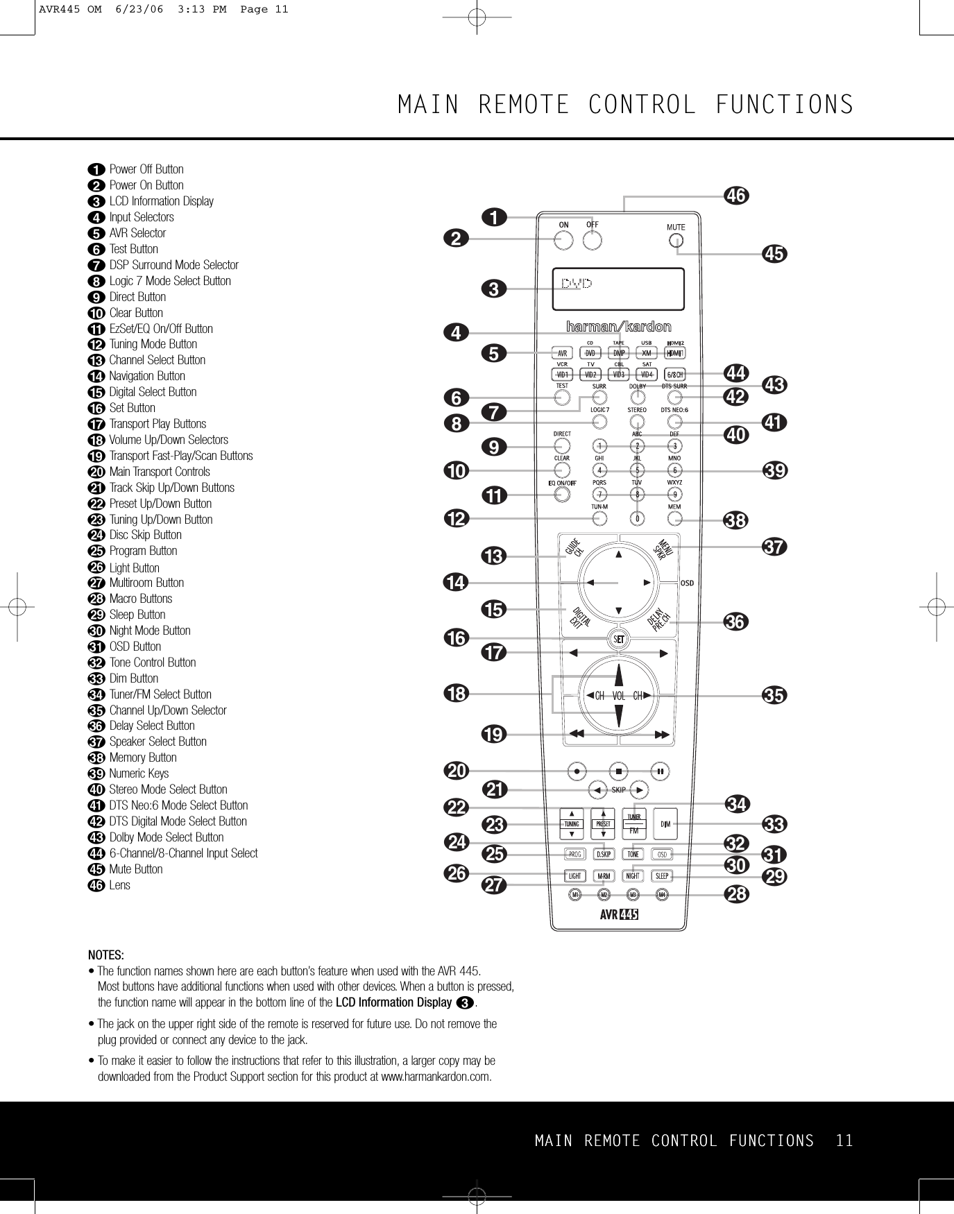
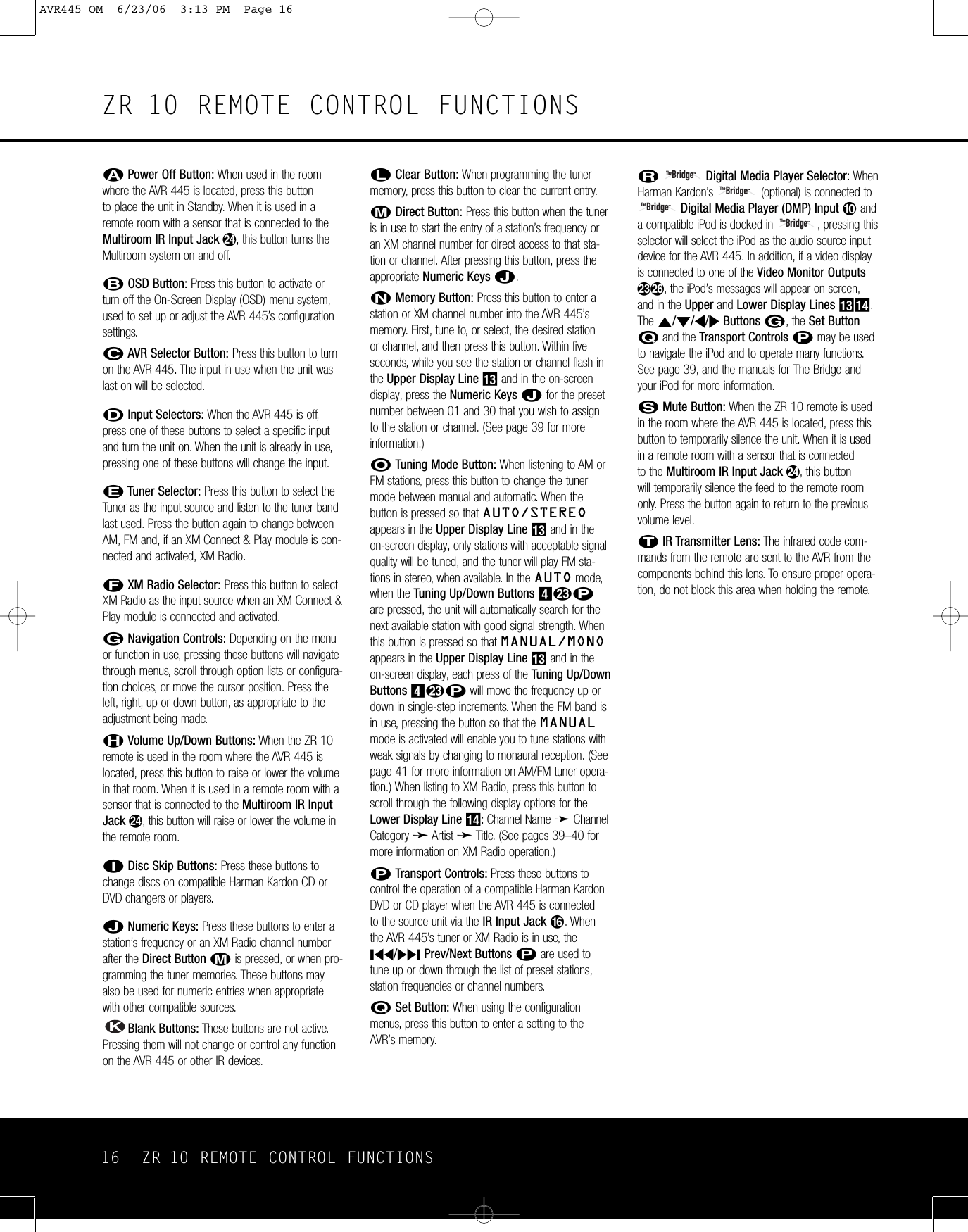
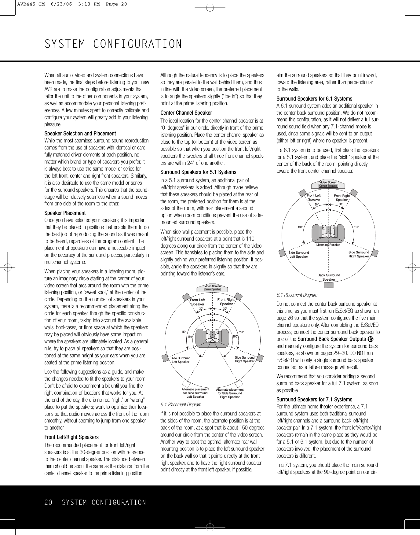
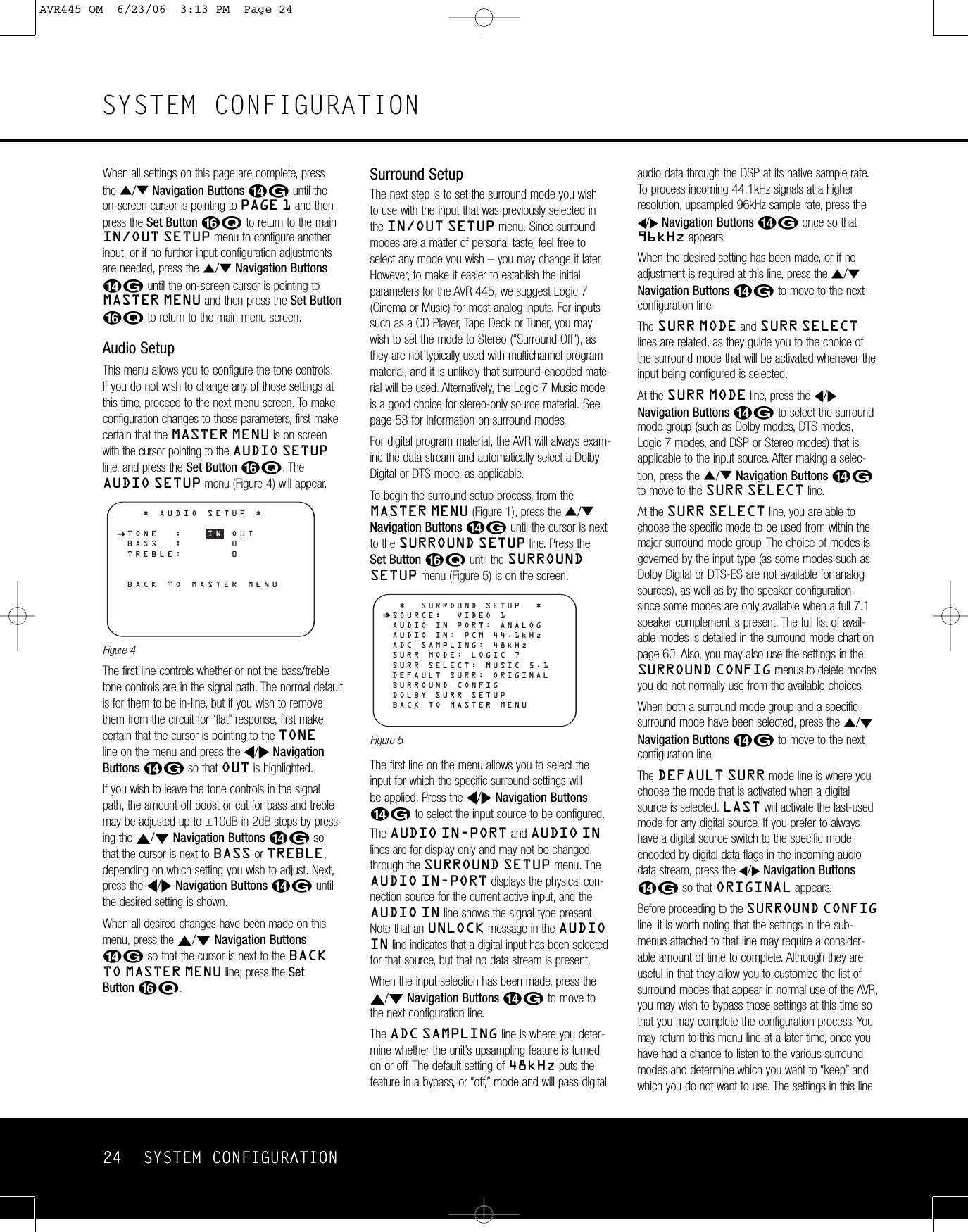
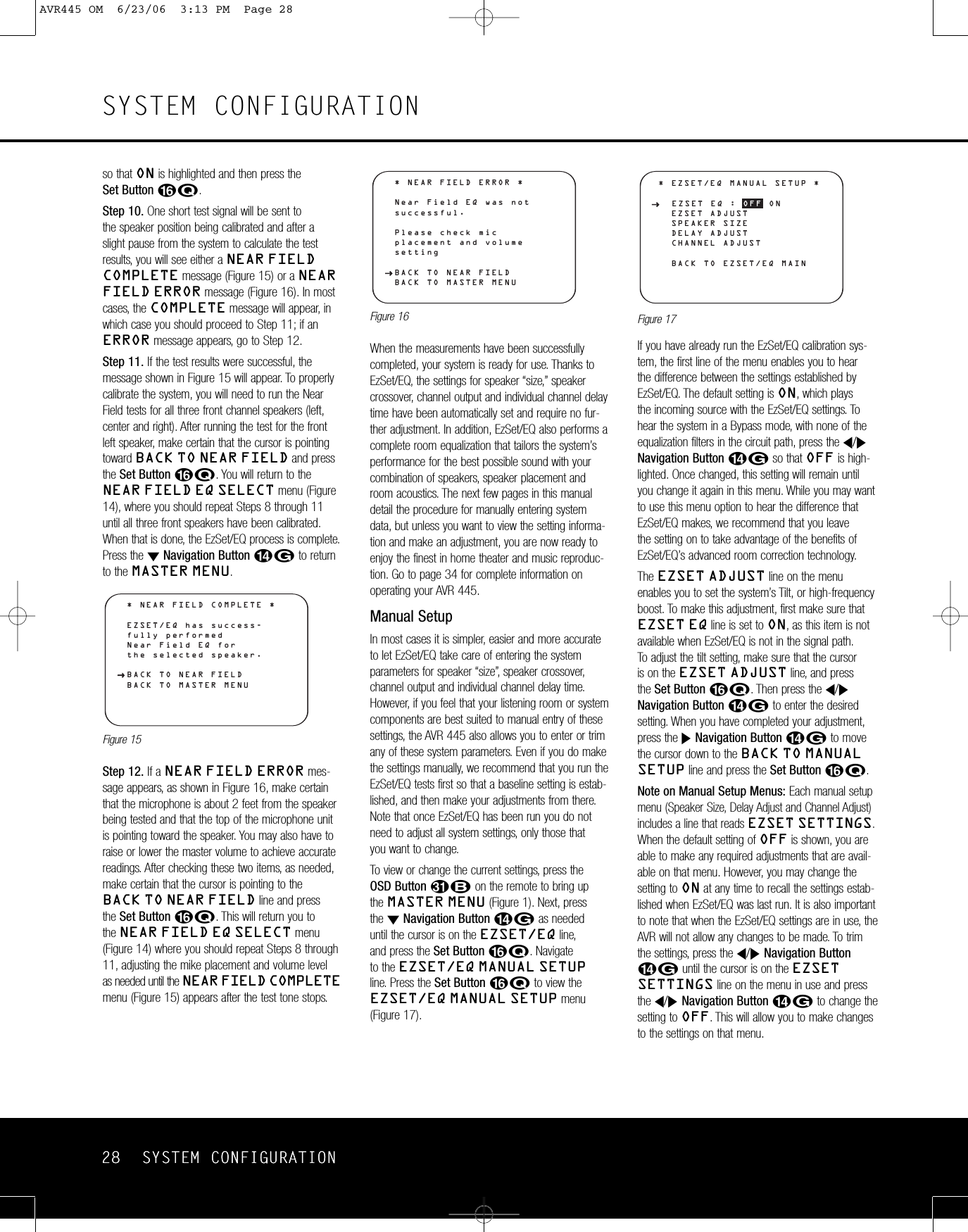
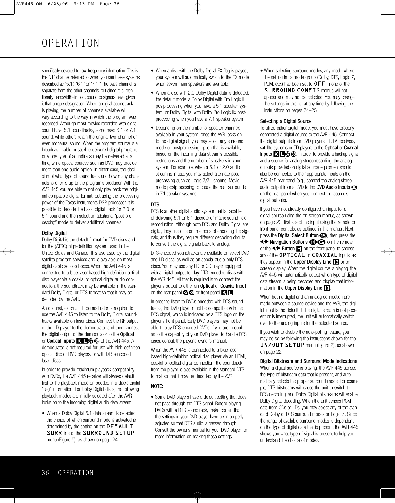
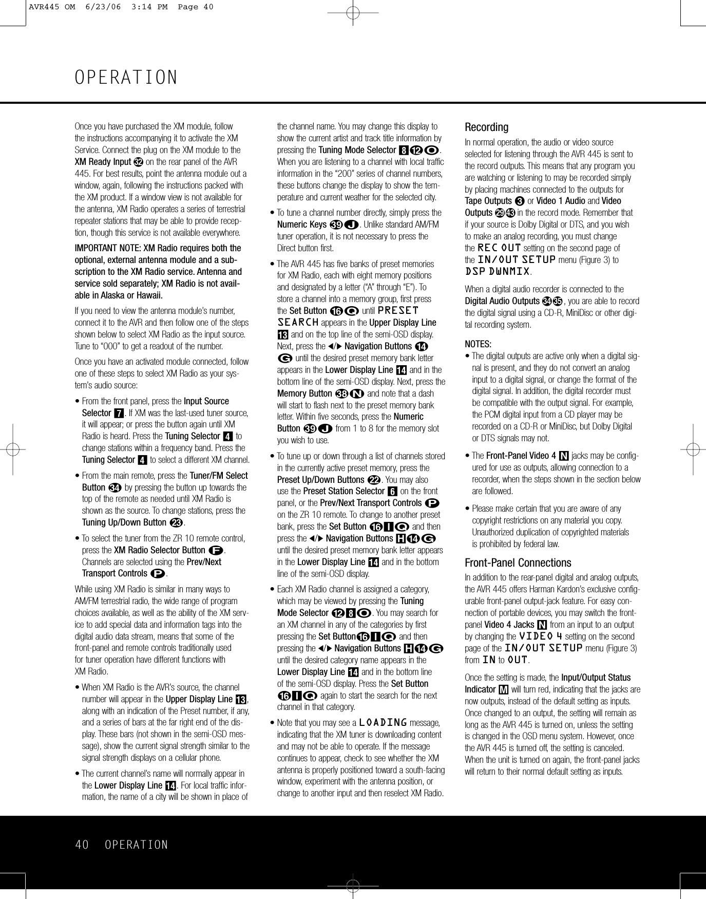
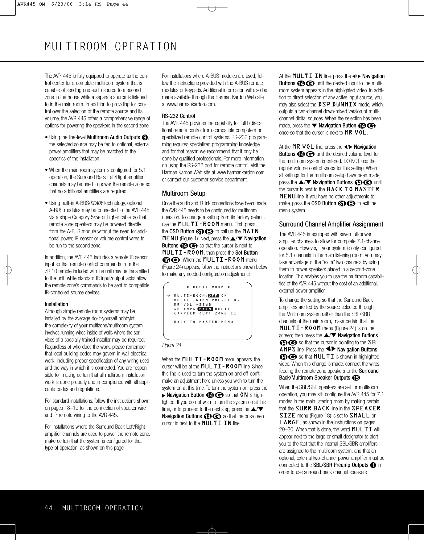
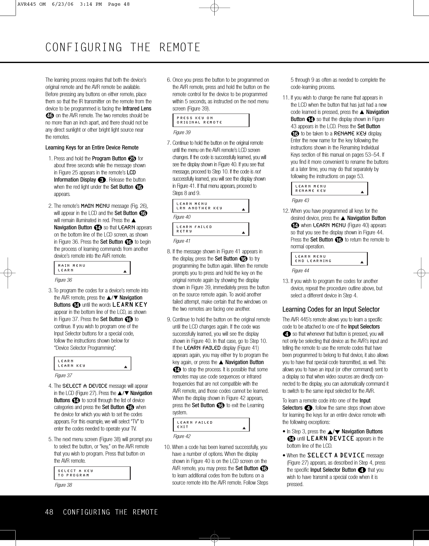
![CONFIGURING THE REMOTE 51CONFIGURING THE REMOTEof the macro to be erased appears, press the Set Button F.Figure 565. The word ERASED will flash four times in thebottom line of the remote’s LCD, and then thedisplay will return to its normal condition. Whenthat happens, the macro is erased and the remoteis returned to normal operation.Read a MacroTocheck the commands stored in the remote’s memoryfor one of the buttons, follow these steps:1. Press and hold the Program ButtonOforabout 3 seconds while the message shown in Figure 25 appears in the remote’s LCDInformation Display2. Release the buttonwhen the red light under the Set Button Fappears.2. The remote’s MAIN MENU message (Fig. 26),will appear in the LCD and the Set Button Fwill remain illuminated in red. Press the ⁄Navigation Button Dso that MACROappears on the bottom line of the LCD screen, asshown in Figure 48. Press the Set Button Fto enter the main macro menu branch.3. At the next menu screen (Figure 57), press the⁄/¤Navigation Button Duntil the bottomline in the remote’sLCD shows READ A MACRO.Press the Set Button Fto begin the processof erasing a macro.Figure 574. The next display screen (Figure 58) is where youselect the macro to be read. Press the ⁄/¤Navigation Button Duntil the name of themacro you wish to read appears. For this example,we will read back the Power On macro created inaprevious section. When the name of the macroto be erased appears, press the Set Button F.Figure 585. As soon as the Set button is pressed, the first twosteps in the macro will be appear in the remote’sLCD screen. You may then use the ⁄/¤Navigation Button Dto step up or downthrough the list of commands stored as themacro. As you read the display, you will see InputSelector Buttons3appear in brackets (e.g.,[AVR]). When the step in the macro is a func-tion, navigation or any other button, it will appearnext to the bracketed readout of the underlyingdevice (e.g., [AVR] POWER ON).6. When you are finished reviewing the macro’s contents, press the Set Button Fto return the remote to normal operation.Punch-Through ConfigurationPunch-through is a capability of the remote that allows the Volume controls, Channel Up/Down buttonsor Transport keys (Play, Stop, Record, Fast Forwardand Reverse, and Skip Up/Down) to link to a differentdevice. For example, if your TV, cable box or satellitereceiver is connected through the AVR 445, you will most likely want to use the AVR 445’s volume control commands even when the remote has been set toissue all other commands for the video device.“Punch-through” enables you to easily program theremote to do this.Volume Punch-ThroughFollow these steps to enable the Volume Up/Downand Mute controls from one device to be used whenthe remote is otherwise programmed for a differentdevice.NOTE FOR VOLUME PUNCH-THROUGH: Theremote’s default settings are for the AVR 445’s vol-ume controls, to be used when any input or device isselected, with the exception of the VID 2/TV button.There is no need to program the remote for volumepunch-through for the AVR 445’scontrols with othersources, such as DVD. To have the AVR 445’s volumecommands used when the TV device is selected, fol-low these steps:1. Press and hold the Program ButtonOforabout 3 seconds while the message shown in Figure 25 appears in the remote’s LCDInformation Display2.Release the buttonwhen the red light under the Set Button Fappears.2. The remote’s MAIN MENU message (Figure26), will appear in the LCD and the Set ButtonFwill remain illuminated in red. Press the⁄/¤Navigation Button Duntil PUNCH-THROUGH appears on the bottom line of theLCD screen, as shown in Figure 59. Press theSet Button Fto enter the main punch-throughmenu branch.Figure 593. At the next menu screen (Figure 60), press the Set Button Fto begin programming theremote for Volume punch-through.Figure 604. The next display screen (Figure 61) is where you select the device that will receive the punch-through commands. In our example, that is the VID 2/TV button, as that is where we want theAVR 445’s volume controls to be active. Press the ⁄/¤Navigation Button Duntil thename of the base device appears and then press the Set Button F.Figure 615. At the next display screen (Figure 62), you willselect the device whose Volume Up/Down andMute commands will be used. Press the ⁄/¤Navigation Button Duntil the desired device’sname appears to the right of the device in use.In our example, that is the AVR 445 (indicated byAVR). When the desired combination of devicesappears, press the Set Button F.Figure 626. When the Set button is pressed, the display willchange to show you that the new combination ofcontrol commands is being saved to the unit’smemory, as shown in Figure 63. The wordSAVED will flash four times and then the remote will return to normal operation.Figure 637. Once the punch-through is programmed, the Volume Up/Down and Mute buttons of the seconddevice named will be used when those buttonsHiare pressed while the master device is in use.Returning the Volume Control Settings to Default OperationIf you wish to remove the Volume punch-through sothat the commands for Volume and Mute are returnedto the factory default setting, follow the steps shownabove, except that in Steps 4 and 5, select the samedevice for both the DEVICE IN USE on the leftside of the bottom line and the PUNCH-THROUGHdevice. In the example used, the display to return theremote to default settings will appear as shown inFigure 64.Figure 64PUNCH-THROUGHTV<-TVTV<-AVR [VOL] SAVEDPUNCH-THROUGHTV<-AVRDEVICE IN USETVPUNCH-THROUGHVOLUMEMAIN MENUPUNCH-THROUGHREAD A MACROPOWER ONMACROREAD A MACROERASE A MACROPOWER ONAVR445 OM 6/23/06 3:14 PM Page 51](https://usermanual.wiki/Woori-Technology/AVR445/User-Guide-683107-Page-51.png)
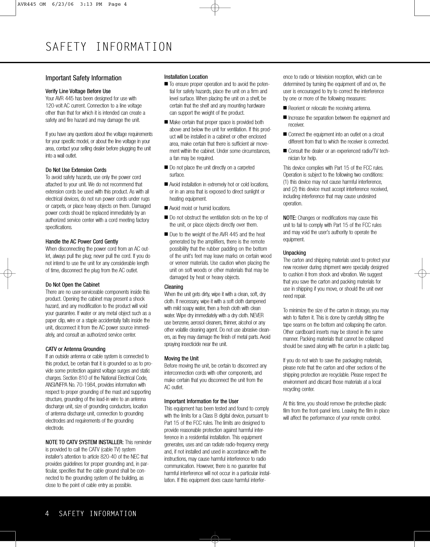
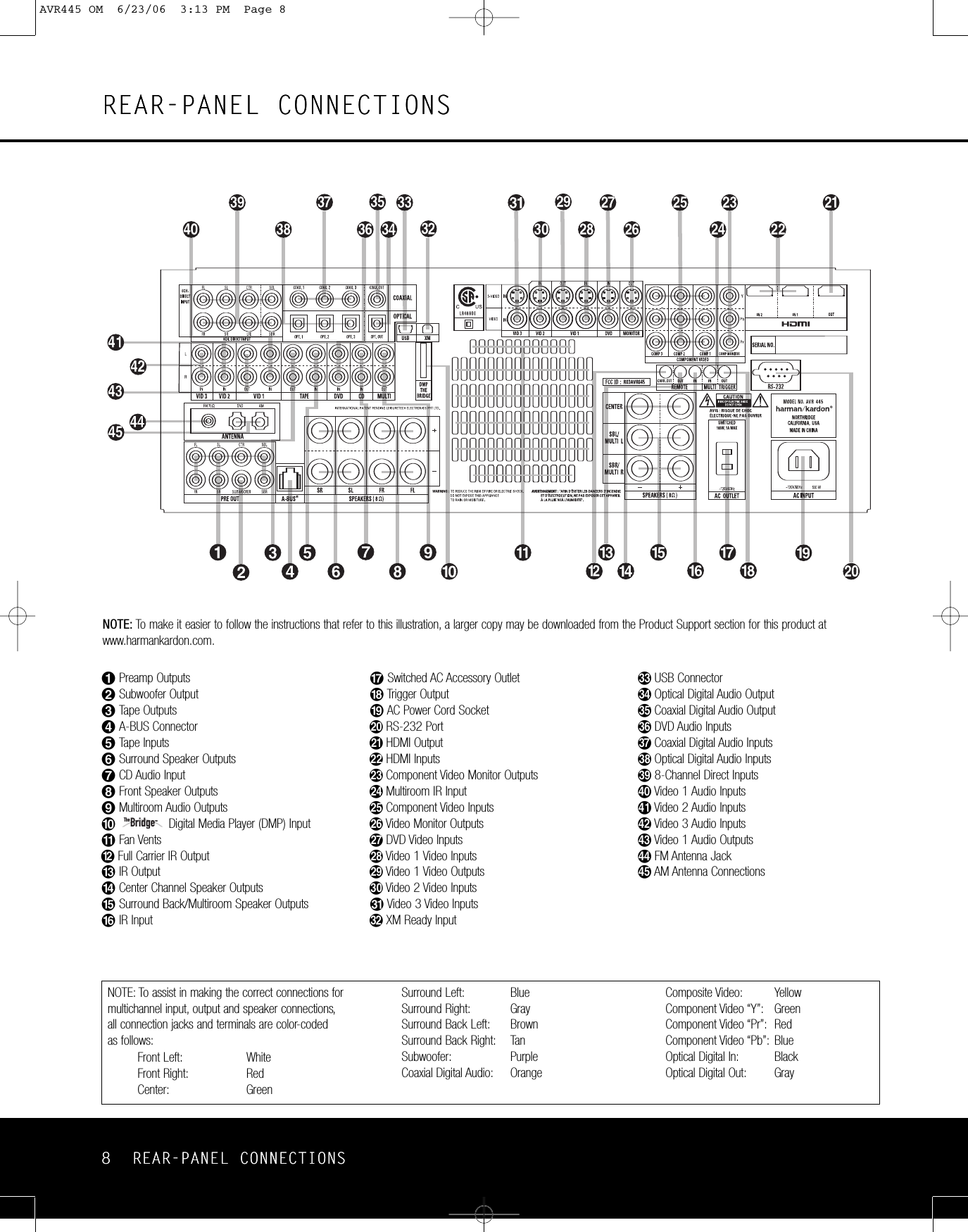
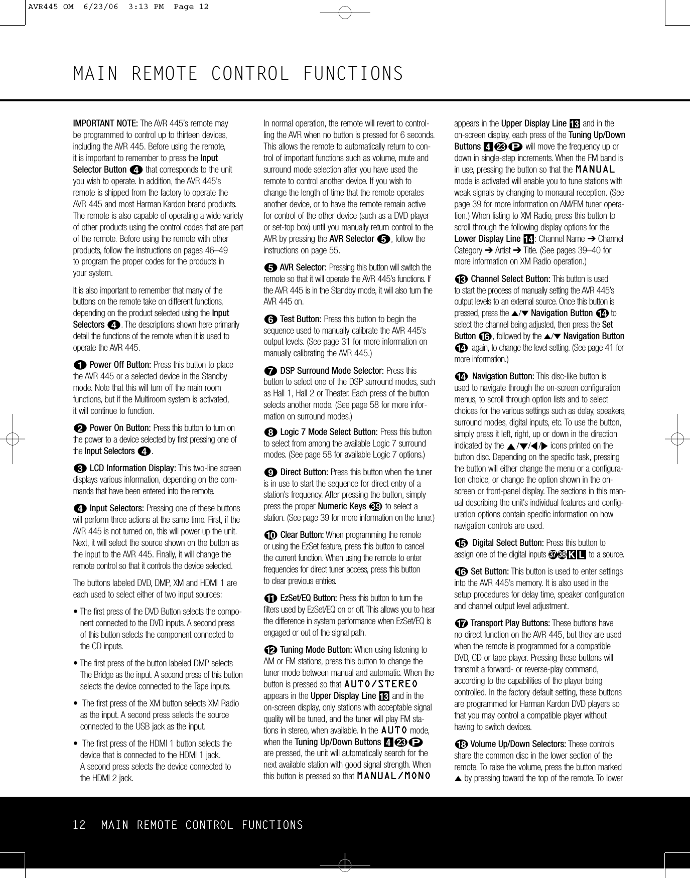
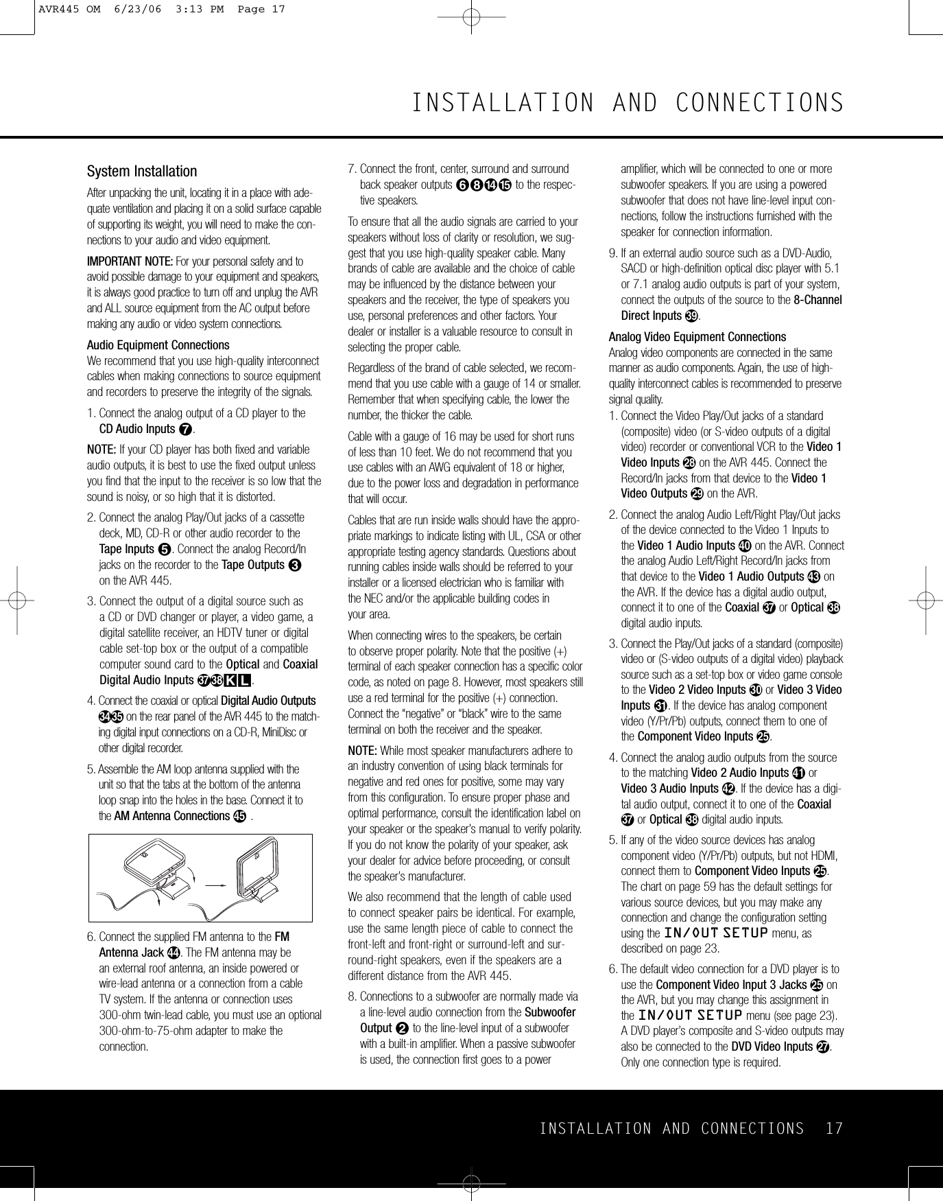
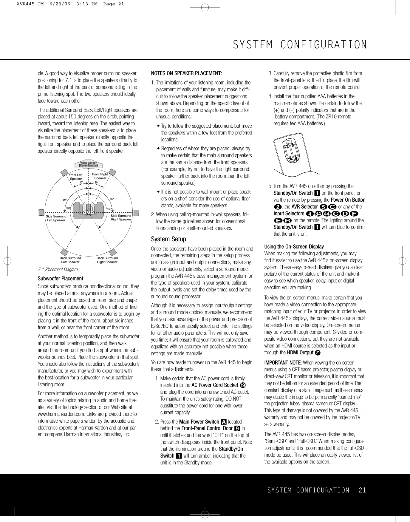
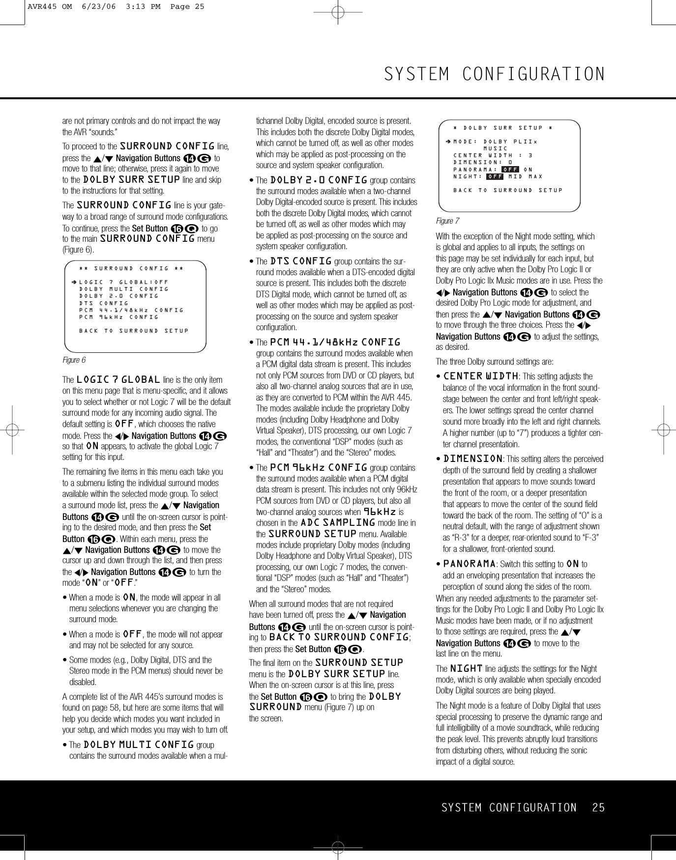
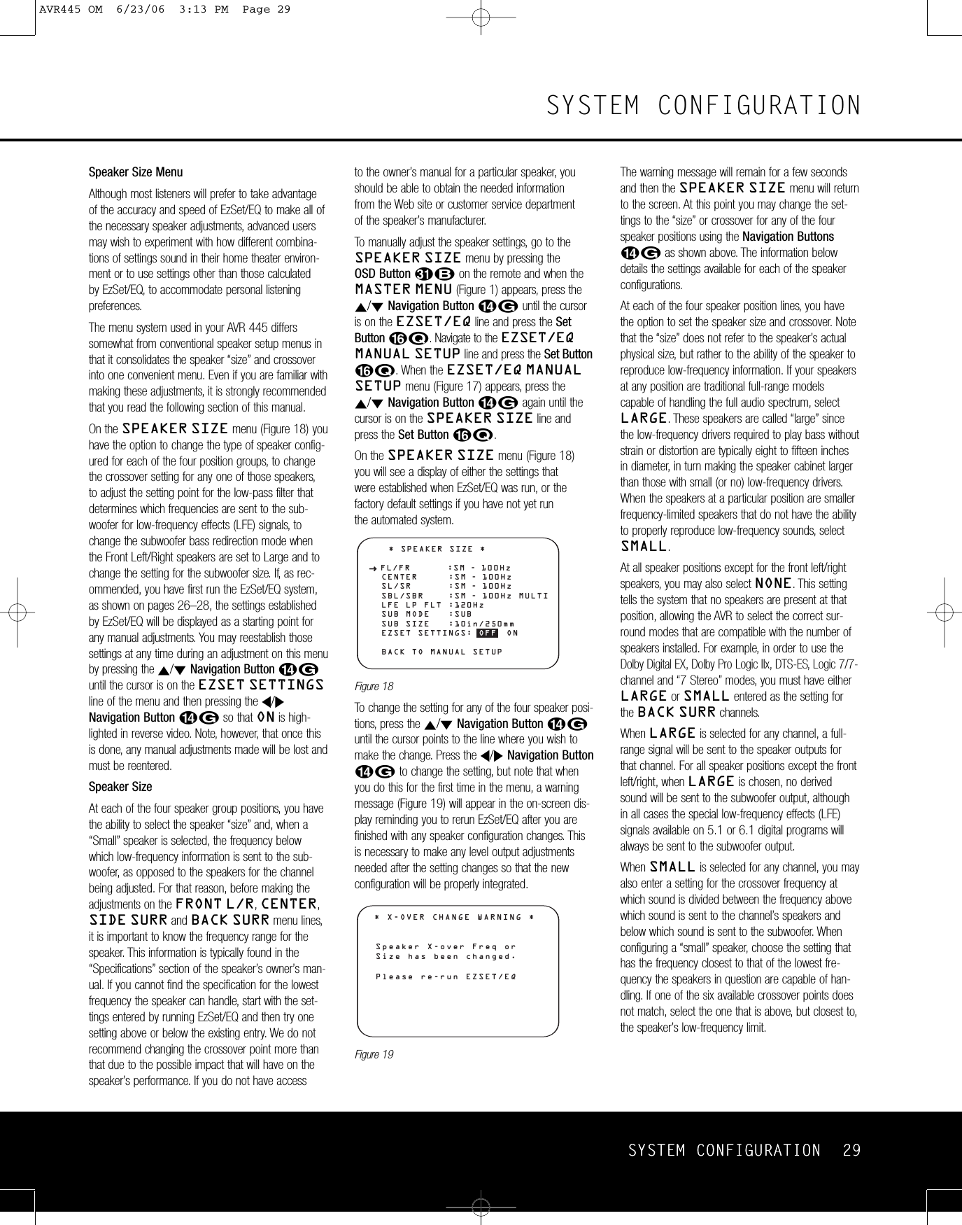
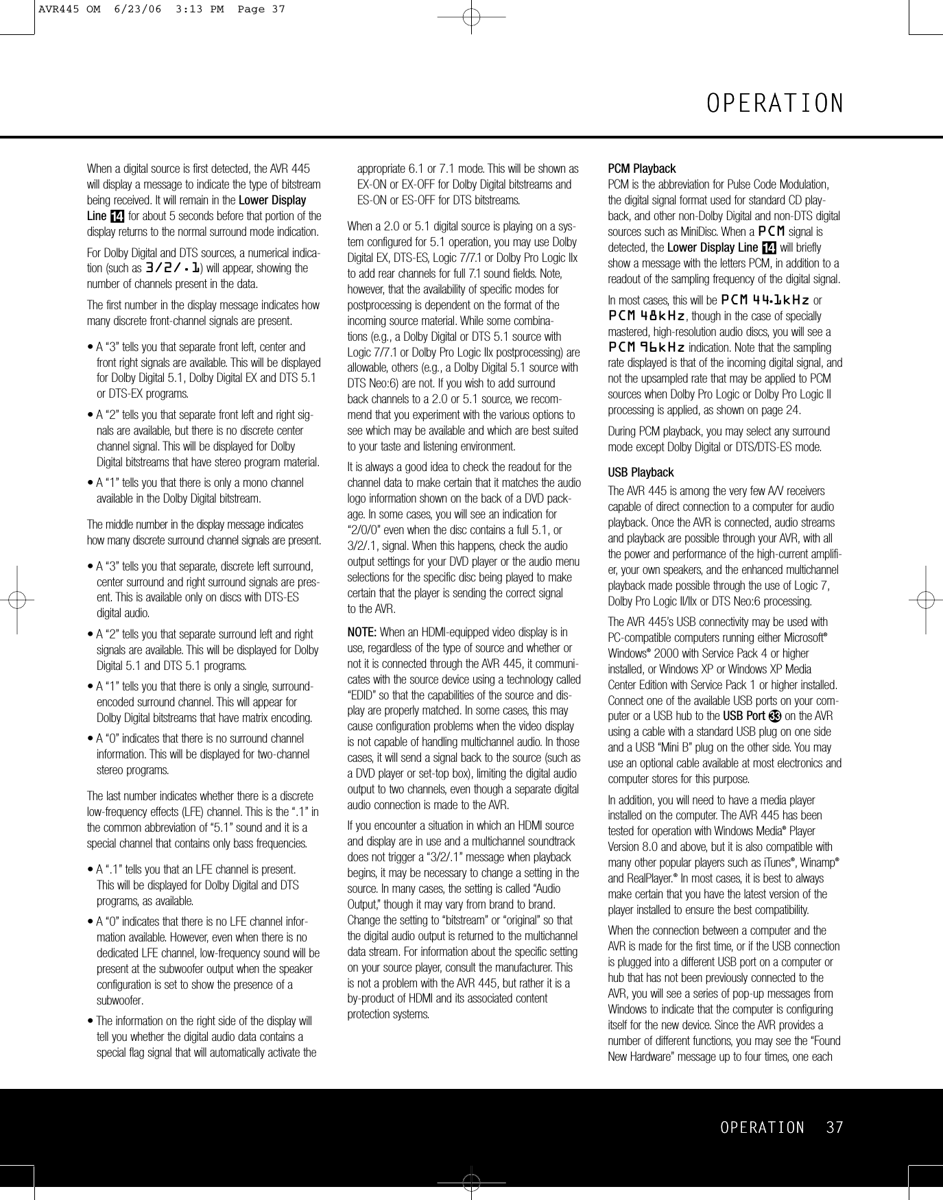
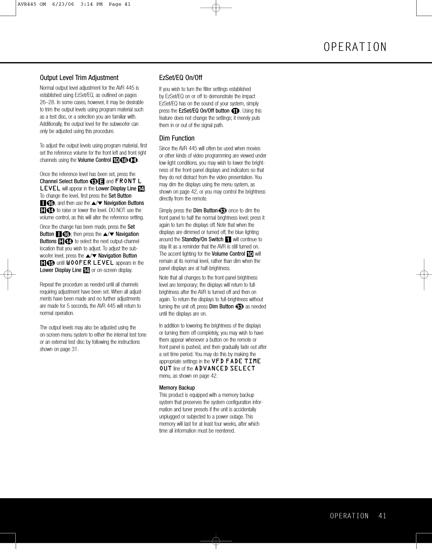
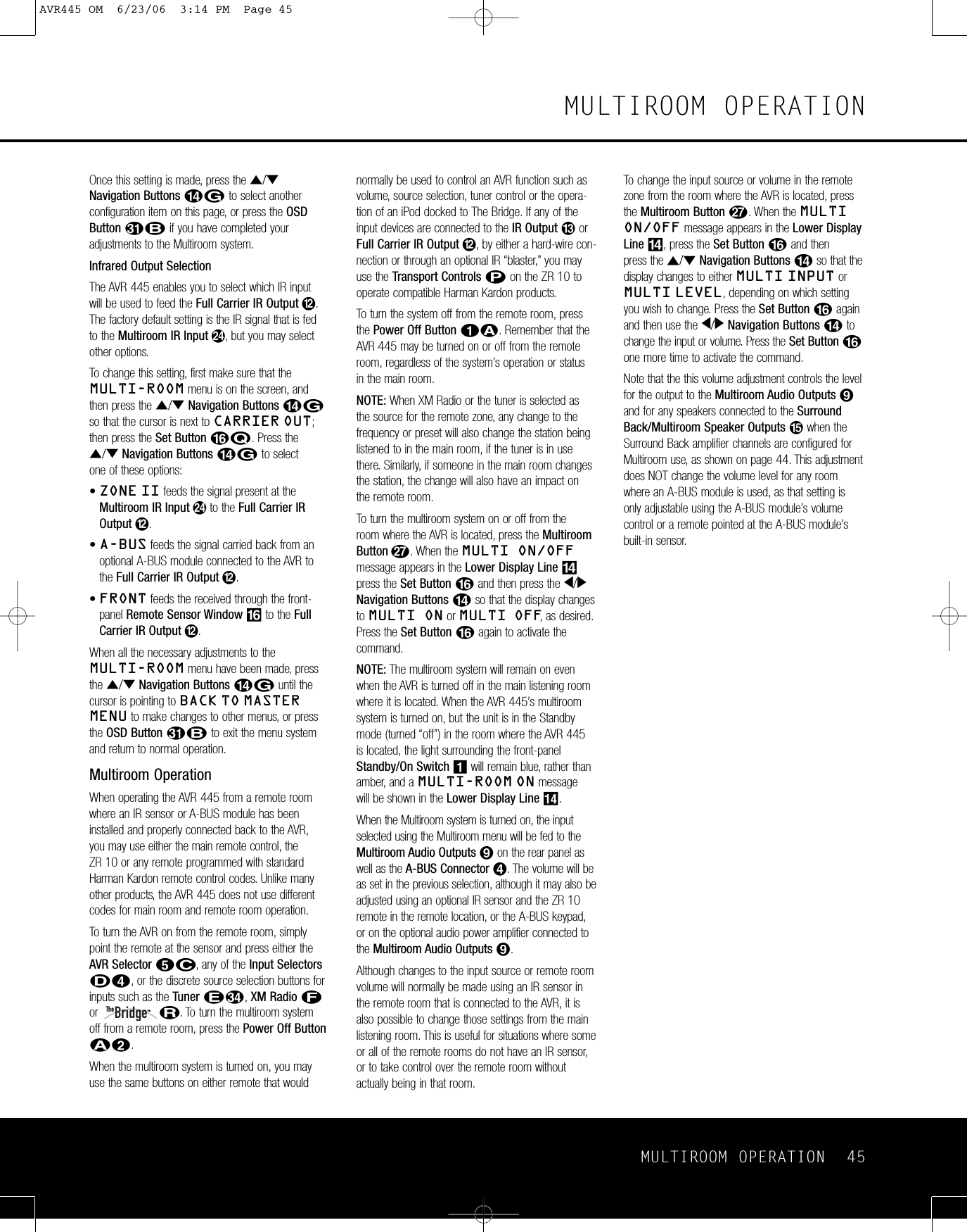
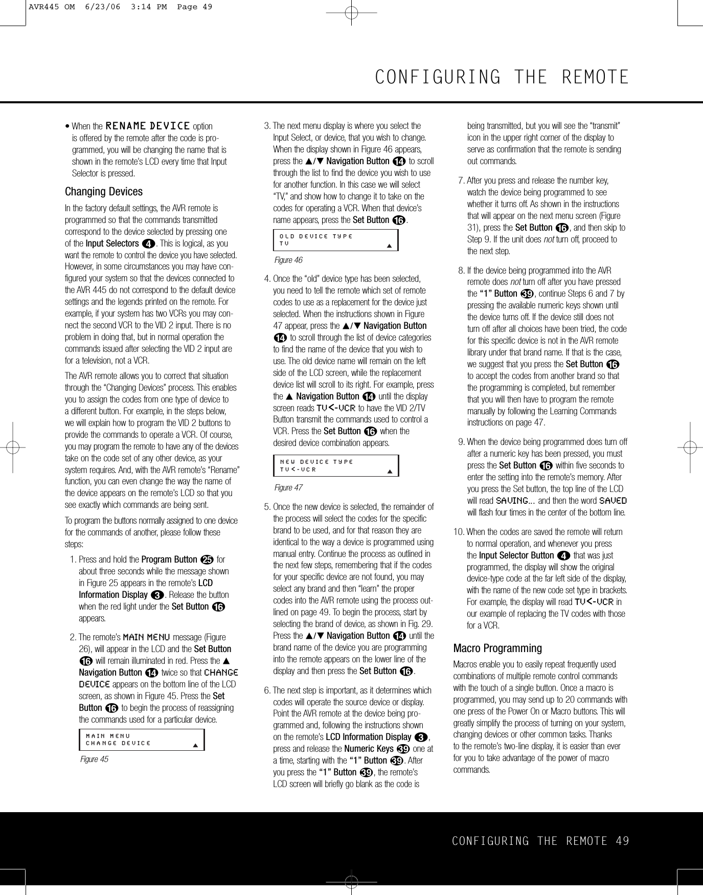
![52 CONFIGURING THE REMOTECONFIGURING THE REMOTEChannel Punch-ThroughChannel punch-through allows the Channel Up/Downbuttons to send commands to a different device thanthe one selected for other commands. For example,you may wish to use a cable box or satellite receiveras the source for a VCR, so you would want theChannel Up/Down Buttons Yto transmit com-mands to the cable box even though the other buttoncommands are programmed to operate the VCR.To program the remote for channel punch-through,follow these steps. This example will show how to program channel punch-through so that the com-mands programmed for Channel Up/Down for theVID 3/Cable device will be transmitted when the VID 1/VCR device has been selected as the current device.1. Press and hold the Program ButtonOforabout 3 seconds while the message shown in Figure 25 appears in the remote’s LCDInformation Display2. Release the buttonwhen the red light under the Set Button Fappears.2. The remote’s MAIN MENU message (Figure26), will appear in the LCD and the Set ButtonFwill remain illuminated in red. Press the⁄/¤Navigation Button Duntil PUNCH-THROUGH appears on the bottom line of theLCD screen, as shown in Figure 59. Press theSet Button Fto enter the main punch-throughmenu branch.3. At the next menu screen, press the ⁄/¤Navigation Button Duntil CHANNELappears on the bottom line of the LCD screen,as shown in Figure 65. Press the Set ButtonFto begin programming the remote forChannel punch-through.Figure 654. The next display screen (Figure 66) is where youselect the device that will receive the punch-through commands.In our example, that is theVID 2/TV button, as that is where we want thecable box’s channel controls to be active. Pressthe ⁄/¤Navigation Button Duntil thename of the base device appears and then press the Set Button F.Figure 665. At the next display screen (Figure 67), you willselect the device whose Channel Up/Down com-mands will be used. Press the ⁄/¤NavigationButton Duntil the desired device nameappears to the right of the device in use. In our example, that is the cable box. When thedesired combination of devices appears, press the Set Button F.Figure 676. When the Set button is pressed, the display willchange to show you that the new combination of control commands is being saved to the unit’smemory, as shown in Figure 68. The wordSAVED will flash four times and then the remote will return to normal operation.Figure 687. Once the punch-through is programmed, theChannel Up/Down Buttons of the second devicenamed will be used when those buttons Yarepressed while the master device is in use.Returning the Channel Control Settings to Default OperationIf you wish to remove the Channel Punch-Through so that the commands for Channel Up/Down arereturned to the factorydefault setting, follow the stepsshown above, except that in Steps 4 and 5, select the same device for both the DEVICE IN USE onthe left side of the bottom line and the PUNCH-THROUGH device. In the example used, the displayto return the remote to default settings will appear asshown in Figure 69.Figure 69Transport Punch-ThroughThe Play G,Stop J,Fast Forward/ReverseI, Pause J, RecordJand Skip Up/DownKTransport Controls are set at the factory to oper-ate your DVD player, or the controls of a specificdevice such as a VCR or CD player when they areselected. However, by using the Transport Punch-Through feature you may program these controls totransmit the commands for a different device. Forexample, you may wish to operate the transport of asecond VCR connected to the VID 2/TV input, asshown in the following example.1. Press and hold the Program ButtonOforabout 3 seconds while the message shown in Figure 25 appears in the remote’s LCDInformation Display2. Release the buttonwhen the light under the Set Button Fturns red.2. The remote’s MAIN MENU message (Figure26), will appear in the LCD and the Set ButtonFwill remain illuminated in red. Press the⁄/¤Navigation Button Duntil PUNCH-THROUGH appears on the bottom line of theLCD screen, as shown in Figure 59. Press theSet Button Fto enter the main punch-throughmenu branch.3. At the next menu screen, press the ⁄/¤Navigation Button Duntil TRANSPORTappears on the bottom line of the LCD screen, asshown in Figure 70. Press the Set Button Fto begin programming the remote for transportpunch-through.Figure 704. The next display screen (Figure 71) selects thedevice that will receive the punch-through com-mands. In our example, that is the TV button, asthat is where we want the VCR’s transport controlsto be active. Press the ⁄/¤Navigation ButtonDuntil the name of the base device appearsand then press the Set Button F.Figure 715. At the next display screen (Figure 72), select thedevice whose transport commands will be used.Press the ⁄/¤Navigation Button Duntil thedesired device name appears to the right of thedevice in use. In our example, that is the VCR.When the desired combination of devicesappears, press the Set Button F.Figure 726. When the Set button is pressed, the display willchange to show you that the new combination ofcontrol commands is being saved to the unit’smemory, as shown in Figure 73. The wordSAVED will flash four times and then the remote will returnto normal operation.Figure 737. Once the punch-through is programmed, the transport buttons of the second device named will be used when those buttons are pressedwhile the master device is in use.TV<-VCR [TRS] SAVEDPUNCH-THROUGHTV<-VCRDEVICE IN USETVPUNCH-THROUGHTRANSPORTPUNCH-THROUGHVCR<-VCRVCR<-CBL [CHAN] SAVEDPUNCH-THROUGHVCR<-CBLDEVICE IN USEVCRPUNCH-THROUGHCHANNELAVR445 OM 6/23/06 3:14 PM Page 52](https://usermanual.wiki/Woori-Technology/AVR445/User-Guide-683107-Page-52.png)
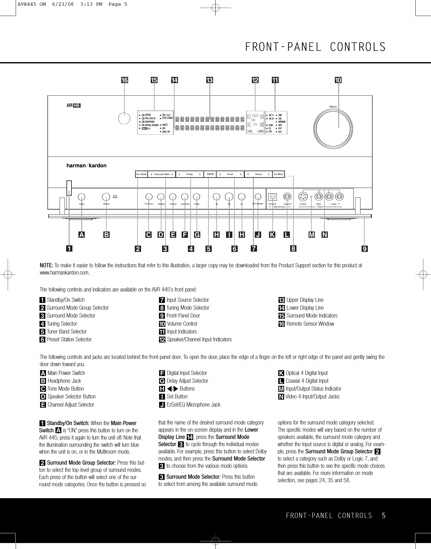
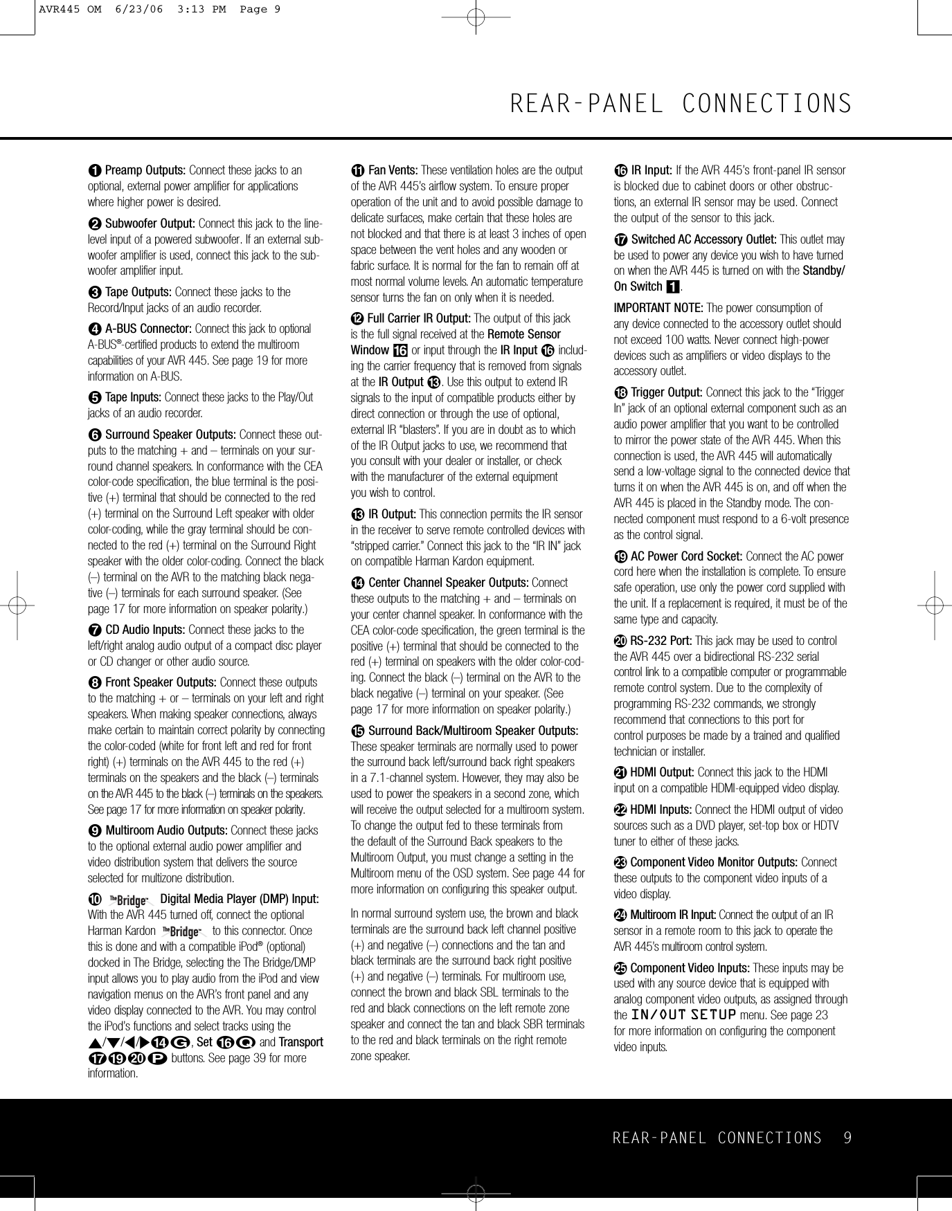
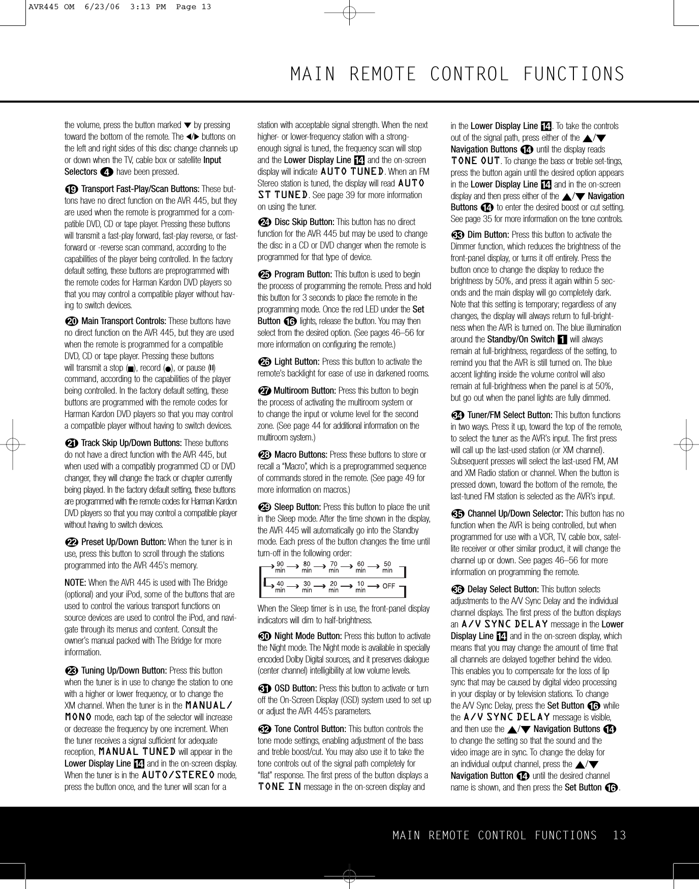
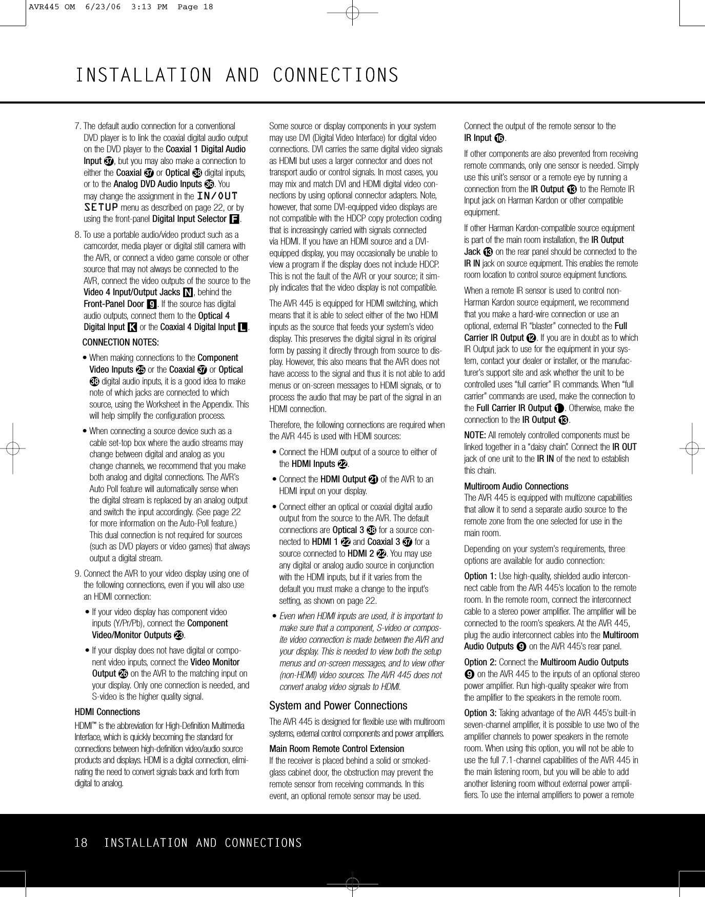
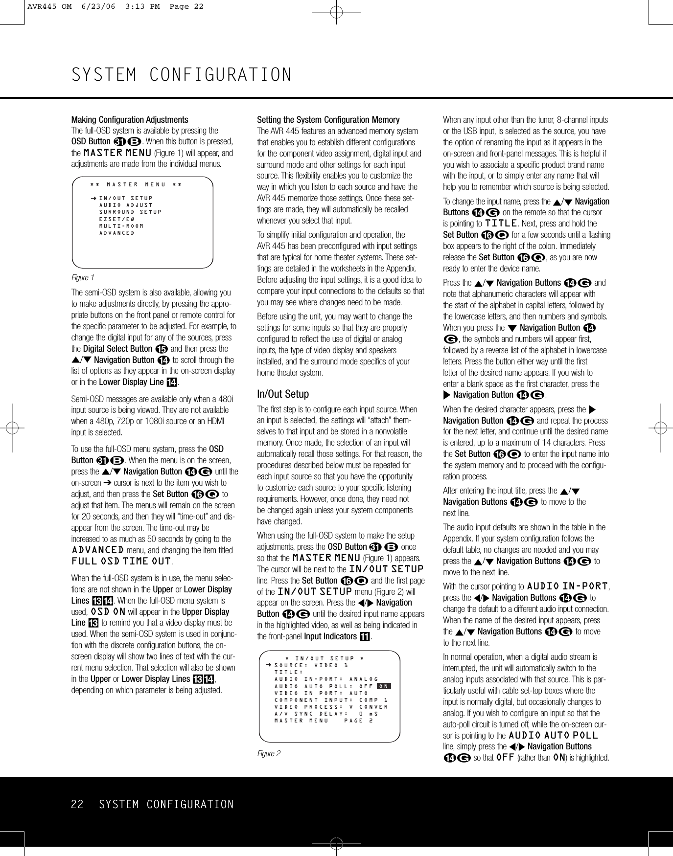
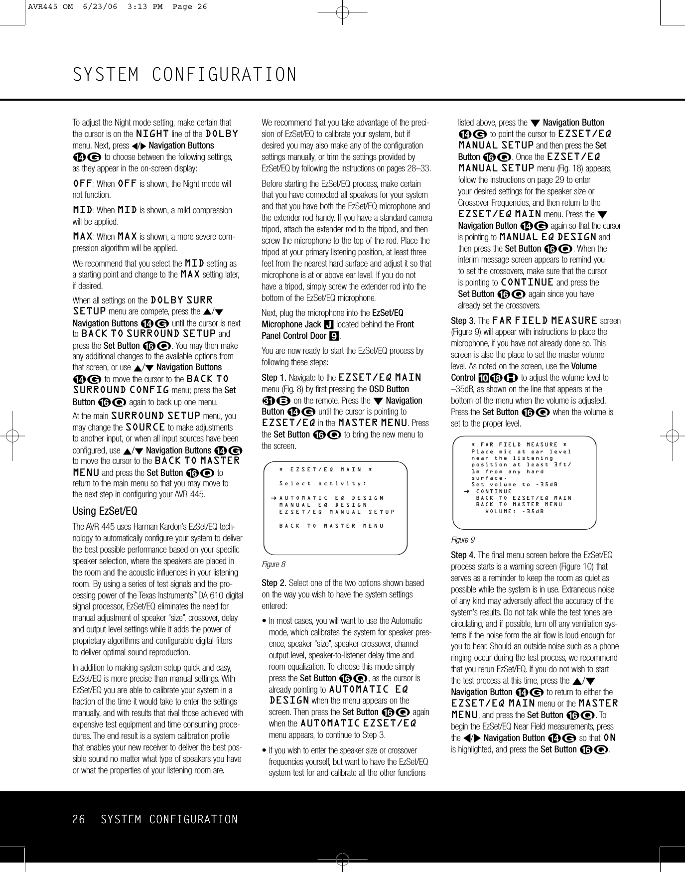
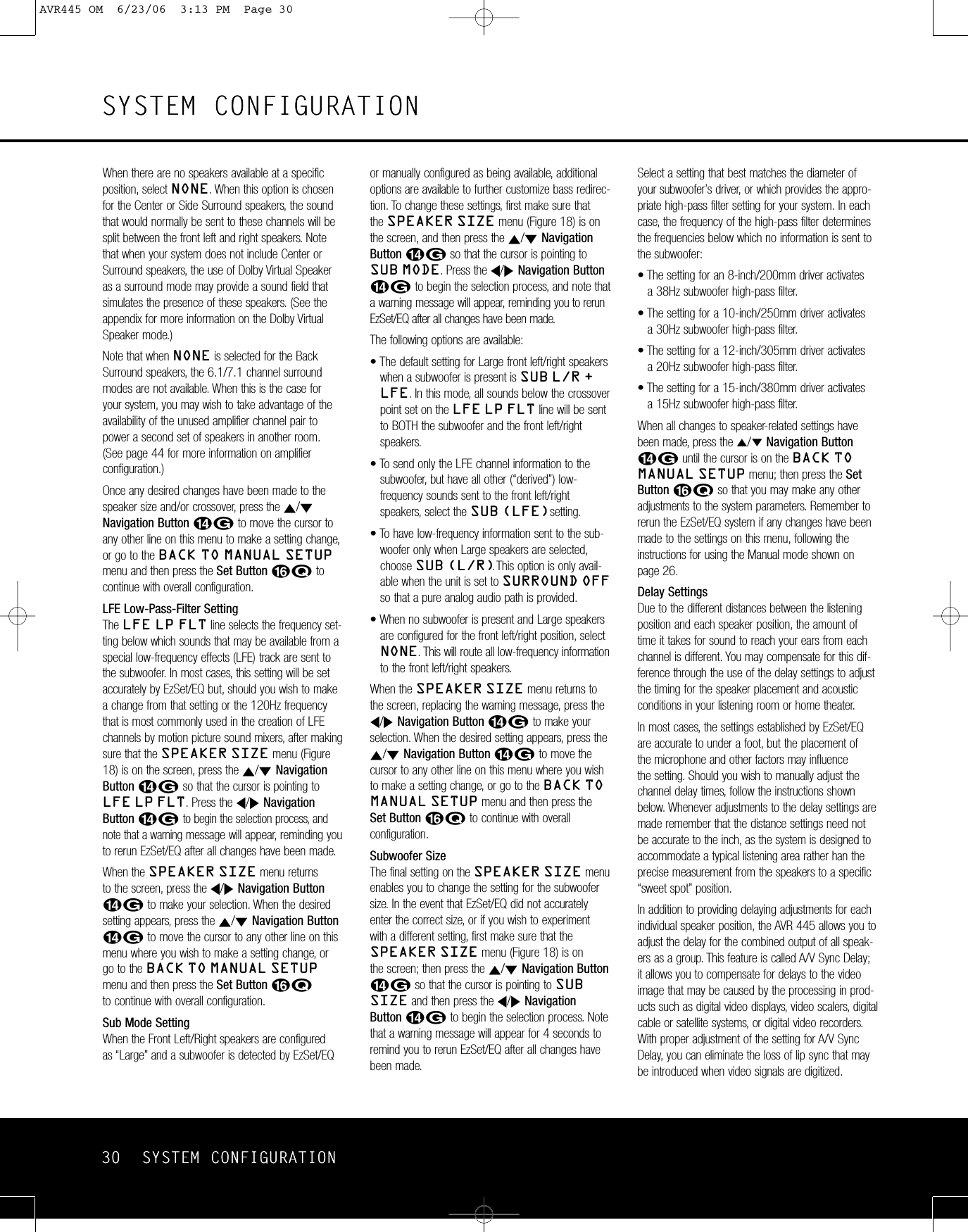
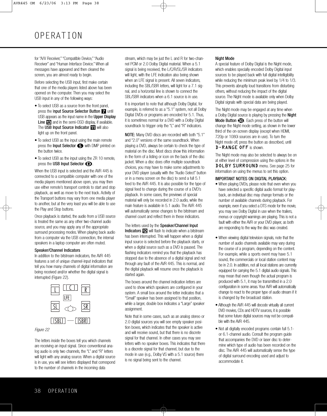
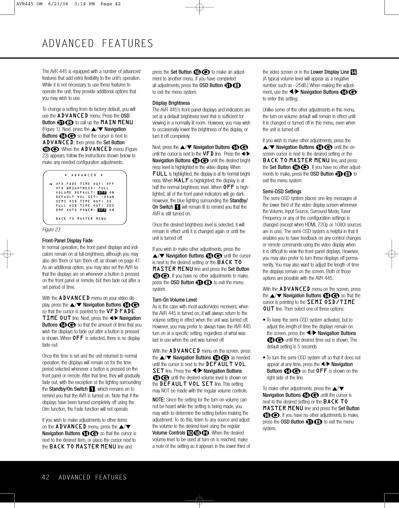
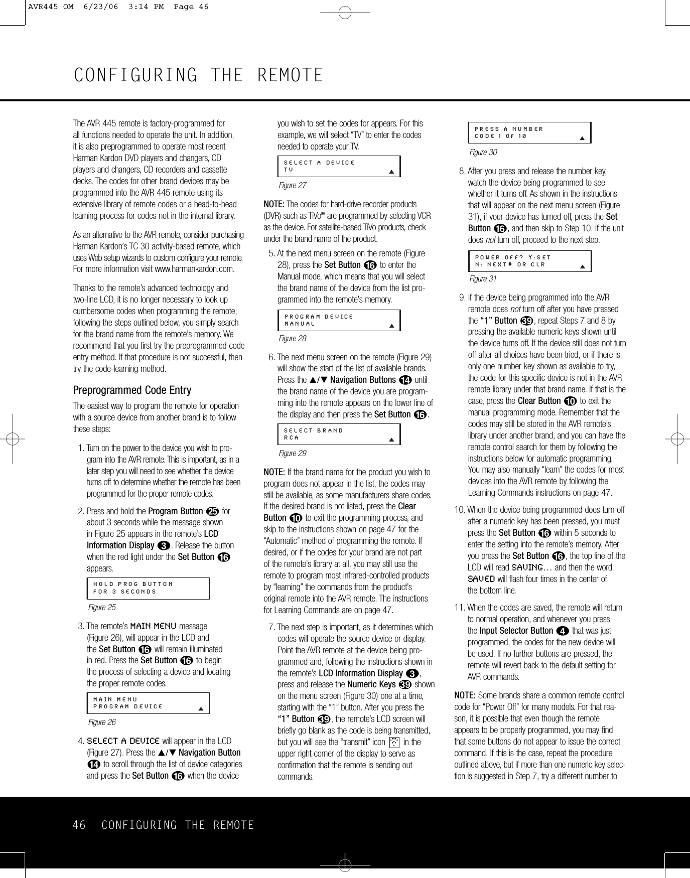
![CONFIGURING THE REMOTE 53CONFIGURING THE REMOTEReturning the Transport Control Settings toDefault OperationIf you wish to remove the Transport Punch-Through sothat the transport commands are returned to the fac-tory default setting, follow the steps shown above,except that in Steps 4 and 5, select the same devicefor both the DEVICE IN USE on the left side of thebottom line and the PUNCH-THROUGH device. Inthe example used, the display to return the remote todefault settings will appear as shown in Figure 74.Figure 74RenamingWhile the names given to the buttons and inputs on the remote represent recognizable categories ofaudio/video products, system operation may be easierif the displays shown in the remote’s LCD screen arecustomized to reflect the specific characteristics of aplayback source’s brand name or the new functiongiven to a specific button when one remote’s controlsare programmed into the AVR remote. The AVRremote allows you to change the name of either amaster device or any button on the remote using thefollowing steps.Renaming a DeviceTo rename a specific device/input source button, fol-low these steps. For this example, we will show youhow to rename the Device/Input Selector normallyshown as “TV” to “HDTV TUNER.”1. Press and hold the Program ButtonOforabout 3 seconds while the message shown in Figure 25 appears in the remote’sLCDInformation Display2. Release the buttonwhen the red light under the Set Button Fappears.2.The remote’sMAIN MENU message (Figure 26),will appear in the LCD and the Set Buttonqwill remain illuminated in red. Press the ⁄/¤Navigation Button Duntil RENAME appearson the bottom line of the LCD screen,as shown in Figure 75.Figure 753. At the next menu screen, press the ⁄/¤Navigation Button Duntil RENAMEDEVICE appears on the bottom line of the LCD screen, as shown in Figure 76. Press the Set Button Fto begin renaming a device.Figure 764. The next display screen (Figure 77) is where you select the device that will be renamed. In our example, that is the TV button. Press the⁄/¤Navigation Button Duntil the name ofthe base device appears and then press theSet Button F.Figure 775. At the next menu screen, you will see the devicename on the bottom line of the display with ablinking cursor box to the right of the devicename. Press the ‹Navigation Button Dtoreturn the blinking cursor to the far left side of thedisplay line. You may then retitle the device nameas shown in the next step.6. To enter the new name, press the Numeric Keysc. The letters above the numbered buttonsindicate which letter or symbol will appear whenthe button is pressed during the renamingprocess. The first press of the button will enter thefirst letter shown, subsequent presses of the samebutton will change the display to the other lettersabove that numbered key. For example, since thefirst letter we need to rename the input to HDTVTuner is an “H”, you would locate the “H” abovethe “4” button, and press the button twice. Thefirst press shows a “G,” the second press changesit to an “H.” Consult the table at the end of thissection to see which characters pressing a partic-ular button generates.7. After you enter the first letter of the new devicename,there are three options for entering the nextcharacter:a. To enter a letter that requires a different numeric key to be pressed, simply press thatbutton. The cursor will automatically move to the next position and the first letter accessed by the new button will appear. Following ourexample, the next letter needed is a “D,” so you would press the “3” button once.b. To enter a letter that uses the same numerickey, you must first press the ›NavigationButton Dto move the blinking cursor blockto the next position. Then press the NumericKey cas required to enter the desired letter.c.To enter a blank space, press the ›NavigationButton Dtwice.The first press will move thecursor to the right, and the second press willmove the cursor one more space to the right,leaving a blank space between the last letterand the next one.8. Repeat Step 7 as needed to enter all the neededletters, numbers, characters and spaces.9. When the text entry is complete, press the Set Button F. The LCD will blink DEVICERENAMED three times and then return to normal operation.Once a device is renamed you will see the new nameon the top line of the remote’s LCD whenever theInput//Device Selector3is pressed, or when anyother command/function button on the remote ispressed after the main Device Selector is pressed.Note that renaming a device in the remote will notchange the name of the input used by the on-screenmenu system of the AVR 445.NOTES ON RENAMING DEVICES:•To move the cursor to the right or left of the displayduring the renaming process, press the ‹/›Navigation Buttons Das required.• The table below shows the letters, numbers andcharacters that may be accessed by pressing theNumeric Keys:Key Characters Key Characters1 [,],/,1 6 M,N,O,62 A,B,C,2 7 P,Q,R,S,73 D,E,F,3 8 T,U,V,84 G,H,I,4 9 W,X,Y,Z,95 J,K,L,5 0 -,.,#,0•Renaming a device changes the name of the device only, not any of the individual key functionswithin that device memory. To change the name ofan individual device, follow the instructions in the next section.Renaming Individual KeysThanks to the programming flexibility of the AVRremote, an individual button on the remote may beassigned a feature or function that is different from thename that appears as the factorydefault when thebutton is pressed. However, with the Rename Keyfunction it is possible to rename almost any button onthe remote so that when the button is pressed you willsee a more descriptive or appropriate name displayed.Torename a specific button on the remote, followthese steps. For this example, we will show you how to rename the DSP Surround Mode Selector6,which is normally not used when DVD is selected,so that it reads ZOOM in the remote’sdisplay.1. Press and hold the Program ButtonOforabout 3 seconds while the message shown in Figure 25 appears in the remote’sLCDInformation Display2. Release the buttonwhen the red light under the Set Button Fappears.RENAME DEVICETVRENAMERENAME DEVICEMAIN MENURENAMEPUNCH-THROUGHTV<-TVAVR445 OM 6/23/06 3:14 PM Page 53](https://usermanual.wiki/Woori-Technology/AVR445/User-Guide-683107-Page-53.png)