Woori Technology AVR445 AV RECEIVER User Manual AVR 445 OM
Woori Technology Inc AV RECEIVER AVR 445 OM
USERS MANUAL
AVR 445
A
AVR 445
AUDIO/VIDEO RECEIVER
OWNER’S MANUAL
Designed to Entertain
.
™
®
AVR445 OM 6/23/06 3:13 PM Page 1
Typographical Conventions
In order to help you use this manual with the remote control, front-panel controls and rear-panel connections,
certain conventions have been used.
EXAMPLE –(bold type) indicates a specific remote control or front-panel button, or rear-panel
connection jack
EXAMPLE –(OCR type) indicates a message that is visible on screen, or on the front-panel
information display
1–(number in a square) indicates a specific front-panel control
A–(letter in a square) indicates a front-panel control that is normally concealed behind the drop-down door
¡–(number in a circle) indicates a rear-panel connection
a–(number in an oval) indicates a button or indicator on the main remote control
å
–(letter in an oval) indicates a button on the ZR 10 remote control
Important note about the instructions in this manual: The appearance of the menus, text and/or cursor in your
receiver’s on-screen menus may vary slightly from the illustrations in this manual. Whether the text appears in
all uppercase or upper- and lowercase characters, performance and operation remain the same.
Please register your product on our Web site at www.harmankardon.com. Note: You’ll need the serial
number of your new AVR. At the same time, you can choose to be notified about our new products
and/or special promotions.
AVR 445 AUDIO/VIDEO RECEIVER
3Introduction
4Important Safety Information
4Unpacking
5Front-Panel Controls
8Rear-Panel Connections
11 Main Remote Control Functions
15 ZR 10 Remote Control Functions
17 Installation and Connections
20 System Configuration
20Speaker Placement
22In/Out Setup
24 Audio Setup
24 Surround Setup
26 Using EzSet/EQ
28 Manual Setup
29 Speaker Size and Crossover
30 Delay Settings
31 Output Level Adjustment
34 Operation
34 Basic Operation
34 Source Selection
35 Volume and Tone Control
35 Surround Mode Selection
35 Digital Audio Playback
37 USB Playback
39 Using The Bridge
39 AM/FM Tuner Operation
39 XM Radio Operation
40 Recording
40 Front-Panel Connections
41 Output Level Trim Adjustment
41 Dim Function
42 Advanced Features
42 Front-Panel Display Fade
42 Display Brightness
42 Turn-On Volume
42 Semi-OSD Settings
43 Full-OSD Time-Out Adjustment
43 DMP/The Bridge Auto Power
44 Multiroom Operation
44 Multiroom Setup
44 Surround Channel Amplifier Assignment
45 Multiroom Operation
46 Configuring the Remote
46 Preprogrammed Code Entry
47 Automatic Code Entry
47 Learning Commands
48 Learning Codes for an Input Selector
49 Changing Devices
49 Macro Programming
51 Punch-Through Configuration
53 Renaming
54 Resetting the Remote
55 Device Priority Timing
57 Troubleshooting Guide
57 Processor Reset
58 Appendix
62 Technical Specifications
62 Trademark Acknowledgements
2 TABLE OF CONTENTS
For Canadian model
Modèle pour les Canadien
Cet appareil numérique de la classe B est conforme
àla norme NMB-003 du Canada.
Sur les modèles dont la fiche est polarisee:
ATTENTION: Pour éviter les chocs électriques, introduire
la lame la plus large de la fiche dans la borne
correspondante de la prise et pousser jusqu’au fond.
This class B digital apparatus complies with Canadian
ICES-003.
For models having a power cord with a polarized plug:
CAUTION: To prevent electric shock, match wide blade
of plug to wide slot, fully insert.
AVR445 OM 6/23/06 3:13 PM Page 2

INTRODUCTION
Thank you for choosing Harman Kardon! With the
purchase of a Harman Kardon®AVR 445, you are
about to begin many years of listening enjoyment.
The AVR 445 has the most extensive range of audio
and video processing, control and connectivity options
ever offered by Harman Kardon, enabling it to provide
the best possible audio and video reproduction with
any type of source material. Teaming advanced pro-
cessing circuitry with proprietary technologies such as
EzSet/EQ, the AVR 445 seamlessly integrates every
component in your entertainment system to deliver the
best possible sound and images.
Some of the leading-edge features that are available
with the AVR 445, such as HDMI™switching and
XM Ready®operation, are new to even the most
experienced home theater enthusiast. Although the
power of the AVR 445 makes them easy to use, we
strongly recommend that you take a few minutes to
read this owner’s manual to familiarize yourself with
how the full suite of AVR 445 features and capabilities
are configured and used in day-to-day operation. This
small investment of time will yield significant dividends
in taking the maximum advantage of this new addition
to your home theater system.
If you have any questions about this product, its instal-
lation or its operation, you may also access a wealth
of information and assistance by visiting our Web site
at www.harmankardon.com.
Description and Features
The AVR 445 serves as the hub of your home enter-
tainment system, providing a wide range of listening
possibilities for almost any audio or video program
source, whether it is the broadcast of a movie or
sporting event in HDTV or a vintage mono or stereo
recording. When playing digital audio sources, the
AVR 445 decodes Dolby®Digital, Dolby Digital EX,
DTS®and DTS-ES®data streams.Two-channel stereo
and matrix surround sources benefit from all current
Dolby Pro Logic®IIx modes and DTS Neo:6.
®The
latest version of our proprietary Logic 7®process is
on-board to create a wider, more enveloping sound
field and more defined surround channel positioning,
regardless of the type of source material. Additional
audio playback options include a direct connection to
compatible computer-based sources through a direct
USB connection.
The AVR 445 takes the “video” part of its name seri-
ously. Along with two HDMI inputs and three 60MHz
analog component video inputs, the AVR 445 converts
composite and S-video to component for single video
connections. The AVR 445 also provides A/V sync
delay so that lip sync errors – commonly seen when
digital video processing is used in a source, program
or video display – are eliminated.
Thanks to a wide range of multizone options and a
standard ZR 10 remote control, the AVR 445 makes
it possible to watch and listen to a separate source in
one room while the main home theater uses a differ-
ent source. Using the assignable rear surround chan-
nel amplifiers, you may create a basic remote listening
zone without any additional equipment, or the unit’s
multiroom outputs may be used to feed an optional,
external power amplifier and volume control. For
one-wire multiroom connectivity, the AVR 445 is
A-BUS/READY®, requiring only a single Category 5/5e
cable run and an optional remote module to power a
pair of remote speakers while controlling volume and
enabling full control over the program source and
connected IR-controlled devices.
Along with the latest advances in digital audio and
video technology, Harman Kardon recognizes that
some things remain constant, and in the case of the
AVR 445 that is a requirement for audio power best
served by our time-honored high-current, ultrawide-
bandwidth amplifier design. The AVR 445’s seven-
channel amplifier provides the power to reproduce the
loudest crescendos or cinema sound effects while
remaining virtually free from distortion or system noise.
With a combination of state-of-the-art circuitry, digital
technology and proven performance with an elegant
design that is compatible with the latest source com-
ponents and video displays, the AVR 445 represents
the culmination of Harman Kardon’s fifty-plus-year
historyof delivering the finest sonic performance.
Í
ÍAll popular digital and matrix surround modes,
including Dolby®Digital, Dolby Digital EX,
Dolby Pro Logic®II, DTS®, DTS-ES®Discrete and
Matrix, DTS Neo:6®and DTS 96/24®
Í
ÍSeven channels of high-current, ultrawide-band-
width amplification with the surround back channels
assignable to either main-room or remote-room use
Í
ÍTwo HDMI™inputs and three assignable high-band-
width analog component inputs for switching the
latest high-definition video sources
Í
ÍConverts composite and S-video sources to com-
ponent video
Í
ÍEzSet/EQ for quick and accurate system setup and
room correction
Í
ÍHarman Kardon’s Logic 7®processing brings a new
sense of reality to stereo and matrix surround
sources
Í
ÍDolby Virtual Speaker processing for use when less
than a full 5.1 or 7.1 speaker complement is
available
Í
ÍDolby Headphone for spacious, open sound when
using headphones
Í
ÍUSB connectivity for audio playback with compatible
computers and quick system upgrades
Í
ÍFull bass management for all inputs, including
the analog direct inputs for high-resolution DVDs,
DVD-Audio and SACD™players, including Quad
Crossover settings and individual settings for
each input
Í
ÍA/V sync delay adjustable for each video input
delivers perfect lip sync with digital programs or
video displays
Í
ÍFront-panel analog audio/video jacks may be used
as either inputs or outputs for connection to the
latest portable products or video game consoles
Í
ÍExtensive multiroom options, including a standard
ZR 10 remote, audio and video outputs to the
remote zone, assignable rear channel amplifier
channels and A-BUS/READY®capability for listening
to a separate source in a remote zone
INTRODUCTION 3
AVR445 OM 6/23/06 3:13 PM Page 3

SAFETY INFORMATION
Important Safety Information
Verify Line Voltage Before Use
Your AVR 445 has been designed for use with
120-volt AC current. Connection to a line voltage
other than that for which it is intended can create a
safety and fire hazard and may damage the unit.
If you have any questions about the voltage requirements
for your specific model, or about the line voltage in your
area, contact your selling dealer before plugging the unit
into a wall outlet.
Do Not Use Extension Cords
To avoid safety hazards, use only the power cord
attached to your unit. We do not recommend that
extension cords be used with this product. As with all
electrical devices, do not run power cords under rugs
or carpets, or place heavy objects on them. Damaged
power cords should be replaced immediately by an
authorized service center with a cord meeting factory
specifications.
Handle the AC Power Cord Gently
When disconnecting the power cord from an AC out-
let, always pull the plug; never pull the cord. If you do
not intend to use the unit for any considerable length
of time, disconnect the plug from the AC outlet.
Do Not Open the Cabinet
There are no user-serviceable components inside this
product. Opening the cabinet may present a shock
hazard, and any modification to the product will void
your guarantee. If water or any metal object such as a
paper clip, wire or a staple accidentally falls inside the
unit, disconnect it from the AC power source immedi-
ately, and consult an authorized service center.
CATV or Antenna Grounding
If an outside antenna or cable system is connected to
this product, be certain that it is grounded so as to pro-
vide some protection against voltage surges and static
charges.Section 810 of the National Electrical Code,
ANSI/NFPA No. 70-1984, provides information with
respect to proper grounding of the mast and supporting
structure, grounding of the lead-in wire to an antenna
discharge unit, size of grounding conductors, location
of antenna discharge unit, connection to grounding
electrodes and requirements of the grounding
electrode.
NOTE TO CATV SYSTEM INSTALLER: This reminder
is provided to call the CATV (cable TV) system
installer’s attention to article 820-40 of the NEC that
provides guidelines for proper grounding and, in par-
ticular, specifies that the cable ground shall be con-
nected to the grounding system of the building, as
close to the point of cable entryas possible.
Installation Location
Í
ÍTo ensure proper operation and to avoid the poten-
tial for safety hazards, place the unit on a firm and
level surface. When placing the unit on a shelf, be
certain that the shelf and any mounting hardware
can support the weight of the product.
Í
ÍMake certain that proper space is provided both
above and below the unit for ventilation. If this prod-
uct will be installed in a cabinet or other enclosed
area, make certain that there is sufficient air move-
ment within the cabinet. Under some circumstances,
afan may be required.
Í
ÍDo not place the unit directly on a carpeted
surface.
Í
ÍAvoid installation in extremely hot or cold locations,
or in an area that is exposed to direct sunlight or
heating equipment.
Í
ÍAvoid moist or humid locations.
Í
ÍDo not obstruct the ventilation slots on the top of
the unit, or place objects directly over them.
Í
ÍDue to the weight of the AVR 445 and the heat
generated by the amplifiers, there is the remote
possibility that the rubber padding on the bottom
of the unit’s feet may leave marks on certain wood
or veneer materials. Use caution when placing the
unit on soft woods or other materials that may be
damaged by heat or heavy objects.
Cleaning
When the unit gets dirty, wipe it with a clean, soft, dry
cloth. If necessary, wipe it with a soft cloth dampened
with mild soapy water, then a fresh cloth with clean
water. Wipe dry immediately with a dry cloth. NEVER
use benzene, aerosol cleaners, thinner, alcohol or any
other volatile cleaning agent. Do not use abrasive clean-
ers, as they may damage the finish of metal parts. Avoid
spraying insecticide near the unit.
Moving the Unit
Before moving the unit, be certain to disconnect any
interconnection cords with other components, and
make certain that you disconnect the unit from the
AC outlet.
Important Information for the User
This equipment has been tested and found to comply
with the limits for a Class B digital device,pursuant to
Part 15 of the FCC rules. The limits are designed to
provide reasonable protection against harmful inter-
ference in a residential installation. This equipment
generates,
uses and can radiate radio-frequency energy
and, if not installed and used in accordance with the
instructions,may cause harmful interference to radio
communication. However, there is no guarantee that
harmful interference will not occur in a particular instal-
lation.If this equipment does cause harmful interfer-
ence to radio or television reception, which can be
determined by turning the equipment off and on, the
user is encouraged to try to correct the interference
byone or more of the following measures:
Í
ÍReorient or relocate the receiving antenna.
Í
ÍIncrease the separation between the equipment and
receiver.
Í
ÍConnect the equipment into an outlet on a circuit
different from that to which the receiver is connected.
Í
ÍConsult the dealer or an experienced radio/TV tech-
nician for help.
This device complies with Part 15 of the FCC rules.
Operation is subject to the following two conditions:
(1) this device may not cause harmful interference,
and (2) this device must accept interference received,
including interference that may cause undesired
operation.
NOTE: Changes or modifications may cause this
unit to fail to comply with Part 15 of the FCC rules
and may void the user’s authority to operate the
equipment.
Unpacking
The carton and shipping materials used to protect your
new receiver during shipment were specially designed
to cushion it from shock and vibration. We suggest
that you save the carton and packing materials for
use in shipping if you move, or should the unit ever
need repair.
Tominimize the size of the carton in storage, you may
wish to flatten it. This is done by carefully slitting the
tape seams on the bottom and collapsing the carton.
Other cardboard inserts may be stored in the same
manner. Packing materials that cannot be collapsed
should be saved along with the carton in a plastic bag.
If you do not wish to save the packaging materials,
please note that the carton and other sections of the
shipping protection are recyclable.Please respect the
environment and discard those materials at a local
recycling center.
At this time,you should remove the protective plastic
film from the front-panel lens. Leaving the film in place
will affect the performance of your remote control.
4SAFETY INFORMATION4SAFETY INFORMATION
AVR445 OM 6/23/06 3:13 PM Page 4
FRONT-PANEL CONTROLS
1Standby/On Switch
2Surround Mode Group Selector
3Surround Mode Selector
4Tuning Selector
5Tuner Band Selector
6Preset Station Selector
7Input Source Selector
8Tuning Mode Selector
9Front-Panel Door
)Volume Control
!Input Indicators
@Speaker/Channel Input Indicators
#Upper Display Line
$Lower Display Line
%Surround Mode Indicators
^Remote Sensor Window
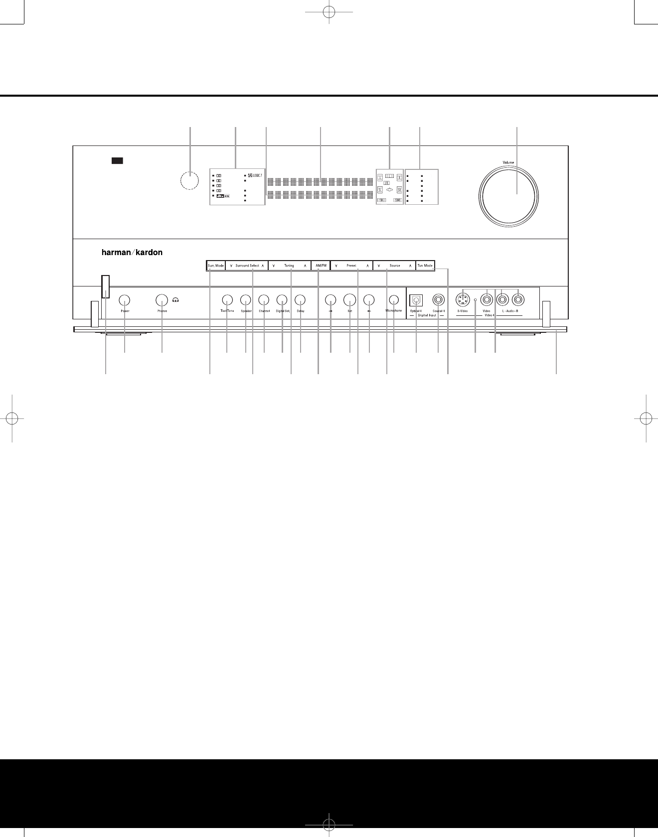
FRONT-PANEL CONTROLS
FRONT-PANEL CONTROLS 55
The following controls and indicators are available on the AVR 445’s front panel:
The following controls and jacks are located behind the front-panel door. To open the door, place the edge of a finger on the left or right edge of the panel and gently swing the
door down toward you.
AMain Power Switch
BHeadphone Jack
CTone Mode Button
DSpeaker Selector Button
EChannel Adjust Selector
FDigital Input Selector
GDelay Adjust Selector
H‹/›Buttons
ISet Button
JEzSet/EQ Microphone Jack
KOptical 4 Digital Input
LCoaxial 4 Digital Input
MInput/Output Status Indicator
NVideo 4 Input/Output Jacks
1Standby/On Switch: When the Main Power
Switch Ais “ON,” press this button to turn on the
AVR 445; press it again to turn the unit off. Note that
the illumination surrounding the switch will turn blue
when the unit is on, or in the Multiroom mode.
2Surround Mode Group Selector: Press this but-
ton to select the top-level group of surround modes.
Each press of the button will select one of the sur-
round mode categories.Once the button is pressed so
that the name of the desired surround mode category
appears in the on-screen display and in the Lower
Display Line $, press the Surround Mode
Selector 3to cycle through the individual modes
available. For example, press this button to select Dolby
modes, and then press the Surround Mode Selector
3to choose from the various mode options.
3Surround Mode Selector: Press this button
to select from among the available surround mode
options for the surround mode category selected.
The specific modes will vary based on the number of
speakers available, the surround mode category and
whether the input source is digital or analog. For exam-
ple, press the Surround Mode Group Selector 2
to select a categorysuch as Dolby or Logic 7,and
then press this button to see the specific mode choices
that are available. For more information on mode
selection, see pages 24, 35 and 58.
NOTE: Tomake it easier to follow the instructions that refer to this illustration, alarger copy may be downloaded from the Product Support section for this product at
www.harmankardon.com.
245679
!
@
#
%
38
ABDEFGH H
IJ K LN
M
)
$
^
1
C
AVR 445
XMFMAM
USB
DMP
TAPE
8CH
6CH
DVD
DIGITAL
PRO LOGIC IIx
HEADPHONE
VIRTUAL SPEAKER
57CH. STEREO
DIRECT
DSP
SURR. OFF
CDMI
HDMI
VID 34
VID 12
AVR445 OM 6/23/06 3:13 PM Page 5

FRONT-PANEL CONTROLS
6FRONT-PANEL CONTROLS
4Tuning Selector: Press the left side of the button
to tune lower-frequency stations and the right side of
the button to tune higher-frequency stations. When
the tuner is in the MANUAL/MONO mode,
each tap of the Selector will increase or decrease the
frequency by one increment. When the tuner receives
asignal strong enough for adequate reception,
MANUAL TUNED will appear in the Lower
Display Line $and in the on-screen display. When
the tuner is in the AUTO/STEREO mode,
press the button once, and the tuner will scan for a
station with acceptable signal strength. When the
next higher- or lower-frequency station is tuned, the
frequency scan will stop and the Lower Display Line
$and the on-screen display will indicate AUTO
TUNED. When an FM stereo station is tuned, the
display will read AUTO ST TUNED. See page
39 for more information on using the tuner. When an
XM Ready module is connected and activated, and
when there is sufficient signal strength for the XM
system to operate, pressing this button will also
change the XM Radio channel.
5Tuner Band Selector: Pressing this button will
automatically switch the AVR 445 to the Tuner mode.
Pressing it again will select the AM or FM frequency
band, or XM Radio. (See page 39 for more informa-
tion on the tuner.)
6Preset Station Selector: Press this button to
scroll up or down through the list of stations that have
been entered into the preset memory. (See page 39
for more information on tuner programming.)
7Input Source Selector: Press this button to
change the input by scrolling up or down through the
list of input sources.
8Tuning Mode Selector: Press this button to select
Auto or Manual tuning. When the button is pressed so
that AUTO/STEREO appears in the Upper
Display Line #,the tuner will search for the next
station with an acceptable signal when the Tuning
Selector 4
M
π
is pressed. When the button is
pressed so that MANUAL/MONO appears in the
Upper Display Line #, each press of the Tuning
Selector 4
M
π
will increase the frequency. (See
page 39 for more information on using the tuner.)
This button may also be used to switch between Stereo
and Mono modes for FM radio reception. When weak
reception is encountered, select the Manual/Mono
tuning mode. Press and hold again to switch back to
Stereo mode. (See pages 39 for more information on
using the tuner.)
When an optional XM Connect & Play module is con-
nected and activated, and when there is sufficient sig-
nal strength for the XM system to operate, this button
has a different set of functions than when traditional
AM or FM radio is in use. See page 39 for more infor-
mation on XM Radio operation.
9Front-Panel Door: To open the door so that the
front-panel jacks and controls behind this door may be
accessed, gently pull the door down and toward you,
using either upper corner of the door.
)Volume Control: Turn this knob clockwise to
increase the volume, counterclockwise to decrease the
volume. If the AVR 445 is muted, adjusting the volume
control will automatically release the unit from the
silenced condition.
!Input Indicators: One of these indicators will light
to identify the currently selected input. Note that the
entire list will light briefly each time the unit is turned
on, as a test.
@Speaker/Channel Input Indicators: These indi-
cators are multipurpose, indicating both the speaker
type selected for each channel and the incoming data-
signal configuration. The left, center, right, right surround
and left surround speaker indicators are composed of
three boxes, while the subwoofer is indicated by one
box. The center box lights when a “small” speaker is
selected, and the two outer boxes light when “large”
speakers are selected. When none of the boxes are
lit for the center, surround or subwoofer channels, no
speaker has been assigned that position. The letters
inside each box display the active input channels. For
standard analog inputs, only the L and R will light, indi-
cating a stereo input. For a digital source, the indicators
will light to display the channels being received at the
digital input. When the letters flash, the digital input has
been interrupted. (See page 38 for more information on
the Channel Indicators.)
#Upper Display Line: Depending on the unit’s
status, a variety of messages will appear here. In
normal operation, this line will show the current input
source and identify whether an analog or digital input
isin use. When the tuner is selected as the input, this
line will identify the station as AM or FM and show the
frequency and preset number, if any.
When an XM Connect & Play module is connected
and activated, and when there is sufficient signal
strength for the XM system to operate, the XM chan-
nel number and signal strength will appear here.
$Lower Display Line: Depending on the unit’s
status, a variety of messages will appear here. In nor-
mal operation, the current surround mode will appear
on this line. When an XM Ready module is connected
and activated, and when there is sufficient signal
strength for the XM system to operate, a variety of
messages and information, including the XM channel
title name, the current artist and track title, the XM
Radio channel category and, when available, local
traffic and weather information, will appear here.
%Surround Mode Indicators: One of these
indicators will light to show the surround mode in
use. Depending on the specific combination of input
sources and surround mode selected, more than
one indicator may light. (See page 36 for more
information.)
^Remote Sensor Window: The sensor behind
this window receives infrared signals from the remote
control.Aim the remote control at this area, and do not
block or cover it unless an external remote sensor
is installed.
AVR445 OM 6/23/06 3:13 PM Page 6
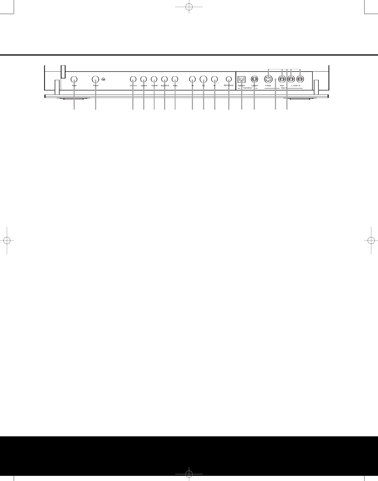
FRONT-PANEL CONTROLS
FRONT-PANEL CONTROLS 7
The following controls and jacks are located behind the front-panel door. To open the door, place the edge of a finger on the left or right edge of the panel and gently swing the
door down toward you.
AMain Power Switch: Press this switch to apply
power to the AVR 445. When the switch is pressed
in, the unit is placed in a Standby mode, as indicated
by the amber illumination surrounding the Standby/On
Switch 1. This button MUST be pressed in to
operate the unit. To turn the unit off and prevent the
use of the remote control, this switch should be
pressed until it pops out from the front panel so that
the word “OFF” may be read at the top of the switch.
NOTE: This switch is normally left in the “ON” position.
BHeadphone Jack: This jack may be used to lis-
ten to the AVR 445’s output through a pair of head-
phones. Be certain that the headphones have a stan-
dard 1/4" stereo phone plug, or that you use an
adapter, as needed, to convert the plug on your head-
phones to the 1/4" jack used on the AVR. When the
headphone jack is in use, the main room speakers
will automatically be turned off and the unit will
output a standard stereo signal. You may also use
the Dolby Headphone mode for an enhanced
listening experience.
CTone Mode Button: This button controls the tone
mode settings, enabling adjustment of the bass and
treble boost/cut. You may also use it to take the tone
controls out of the signal path completely for “flat”
response. The first press of the button displays a
TONE MODE message in the Lower Display
Line $and in the on-screen display. To take the
controls out of the signal path, press either of the
‹/›Buttons Huntil the display reads TONE
OUT. To change the bass or treble settings, press
the button again until the desired option appears in the
Lower Display Line $and in the on-screen display
and then press either of the ‹/›Buttons Hto
enter the desired boost or cut setting. See page 35
for more information on the tone controls.
DSpeaker Selector Button: Press this button
to begin the process of manually configuring the
AVR 445 for the type of speakers it is being used
with. For complete information on configuring the
speaker settings, see page 29.
EChannel Adjust Selector: Press the button to
begin the process of manually adjusting the channel
level outputs using the source currently playing
through your AVR. For complete information on
adjusting the channel output level, see page 41.
FDigital Input Selector: Press this button to begin
the process of selecting a digital source for use with
the currently selected input. Once the button has been
pressed, use the ‹/›Buttons Hto choose the
desired input and then press the Set Button Ito
enter the setting into the unit’smemory. See page 35
for more information on digital audio.
GDelay Adjust Selector: Press this button to begin
the process of adjusting the delay settings. See page
30 for more information on delay adjustments.
H‹/›Buttons: When making system configura-
tion changes using the front-panel controls, press
these buttons to scroll through the available choices
for the option being adjusted.
ISet Button: When making system configuration
changes using the front-panel controls, press this but-
ton to enter a setting into the unit’s memory.
JEzSet/EQ Microphone Jack: Before starting the
EzSet/EQ automated setup process, plug the micro-
phone into this jack. The microphone does not need
to be plugged in at other times.
KOptical 4 Digital Input: Connect the optical digital
output of an audio or video product to this jack.
LCoaxial 4 Digital Input: Connect the coaxial
digital output of a digital audio product such as a
portable audio player or video game to this jack.
MInput/Output Status Indicator: This LED
indicator will normally light green to show that the front-
panel Video 4 Input/Output Jacks Nare operating
as inputs. When these jacks are configured for use as
outputs, the indicator will turn red to show that the jack
may be used as an output for recording. (See pages 22
and 40 for more information on configuring the front-
panel jacks as outputs, rather than inputs.)
NVideo 4 Input/Output Jacks: These audio/video
jacks may be used as either inputs or outputs for
temporary connection to video games or portable
audio/video products such as camcorders and
portable audio players. (See pages 22 and 40 for
more information on switching these jacks between
inputs and outputs.)
ABDEFGH H
IJ K LN
M
C
AVR 445
XMFMAM
USB
DMP
TAPE
8CH
6CH
DVD
DIGITAL PLUS
PRO LOGIC IIx
HEADPHONE
VIRTUAL SPEAKER
57CH. STEREO
DIRECT
DSP
SURR. OFF
CDMI
HDMI 12
VID 34
VID 12
AVR445 OM 6/23/06 3:13 PM Page 7
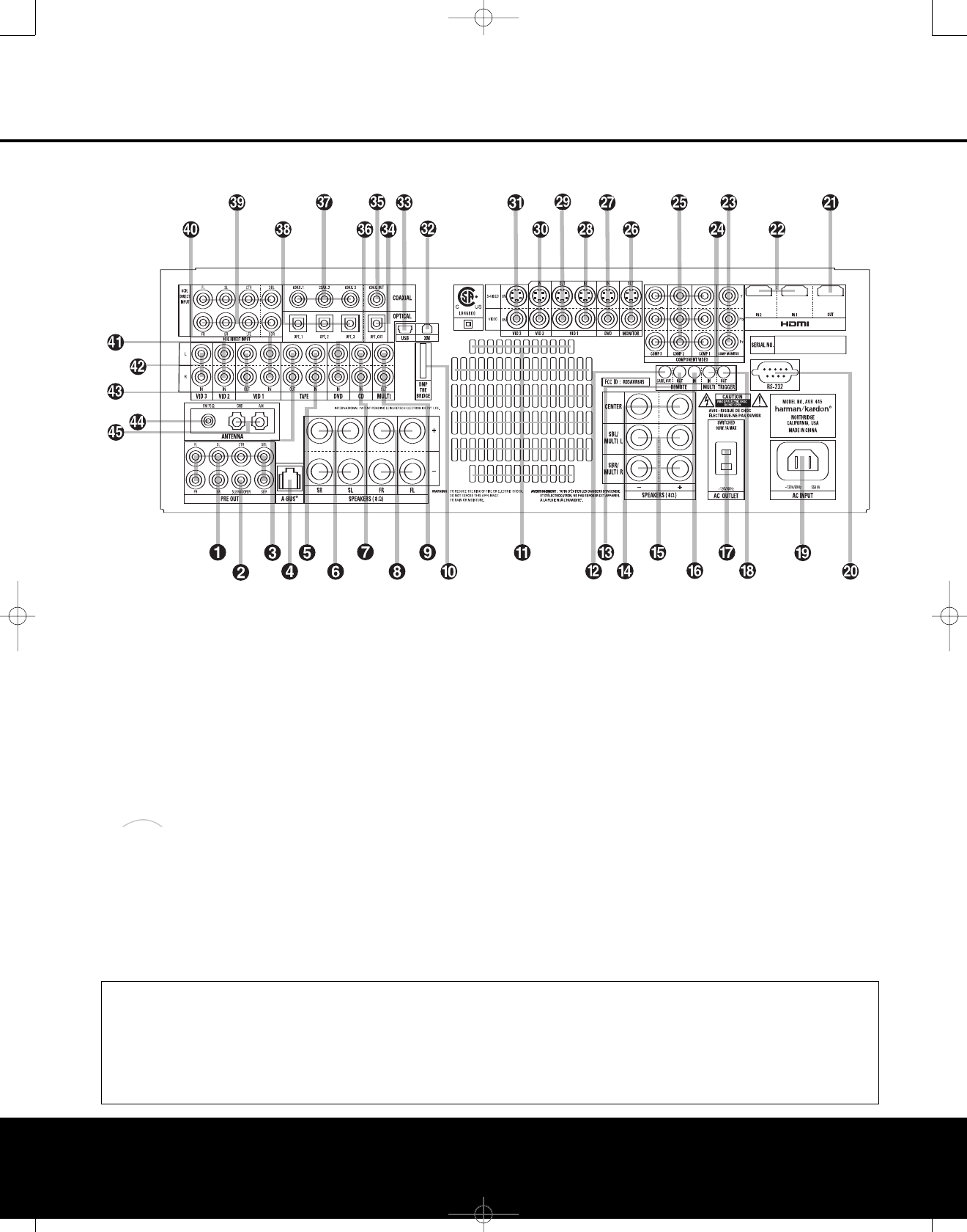
8REAR-PANEL CONNECTIONS
REAR-PANEL CONNECTIONS
0Preamp Outputs
1Subwoofer Output
2Tape Outputs
3A-BUS Connector
4Tape Inputs
5Surround Speaker Outputs
6CD Audio Input
7Front Speaker Outputs
8Multiroom Audio Outputs
9Digital Media Player (DMP) Input
AFan Vents
BFull Carrier IR Output
CIR Output
DCenter Channel Speaker Outputs
ESurround Back/Multiroom Speaker Outputs
FIR Input
GSwitched AC Accessory Outlet
HTrigger Output
IAC Power Cord Socket
JRS-232 Port
KHDMI Output
LHDMI Inputs
MComponent Video Monitor Outputs
NMultiroom IR Input
OComponent Video Inputs
PVideo Monitor Outputs
QDVD Video Inputs
RVideo 1 Video Inputs
SVideo 1 Video Outputs
TVideo 2 Video Inputs
UVideo 3 Video Inputs
VXM Ready Input
WUSB Connector
XOptical Digital Audio Output
YCoaxial Digital Audio Output
ZDVD Audio Inputs
aCoaxial Digital Audio Inputs
bOptical Digital Audio Inputs
c8-Channel Direct Inputs
dVideo 1 Audio Inputs
eVideo 2 Audio Inputs
fVideo 3 Audio Inputs
gVideo 1 Audio Outputs
hFM Antenna Jack
iAM Antenna Connections
The
Bridge
TM
NOTE: Toassist in making the correct connections for
multichannel input, output and speaker connections,
all connection jacks and terminals are color-coded
as follows:
Front Left: White
Front Right: Red
Center: Green
Surround Left: Blue
Surround Right: Gray
Surround Back Left: Brown
Surround Back Right: Tan
Subwoofer:Purple
Coaxial Digital Audio: Orange
Composite Video:Yellow
Component Video “Y”: Green
Component Video “Pr”: Red
Component Video “Pb”: Blue
Optical Digital In: Black
Optical Digital Out: Gray
REAR-PANEL CONNECTIONS
8REAR-PANEL CONNECTIONS
NOTE: To make it easier to follow the instructions that refer to this illustration, a larger copy may be downloaded from the Product Support section for this product at
www.harmankardon.com.
AVR445 OM 6/23/06 3:13 PM Page 8

REAR-PANEL CONNECTIONS 9
REAR-PANEL CONNECTIONS
0Preamp Outputs: Connect these jacks to an
optional, external power amplifier for applications
where higher power is desired.
1Subwoofer Output: Connect this jack to the line-
level input of a powered subwoofer. If an external sub-
woofer amplifier is used, connect this jack to the sub-
woofer amplifier input.
2Tape Outputs: Connect these jacks to the
Record/Input jacks of an audio recorder.
3A-BUS Connector:
Connect this jack to optional
A-BUS®-certified products to extend the multiroom
capabilities of your AVR 445. See page 19 for more
information on A-BUS.
4
Tape Inputs: Connect these jacks to the Play/Out
jacks of an audio recorder.
5Surround Speaker Outputs: Connect these out-
puts to the matching + and – terminals on your sur-
round channel speakers. In conformance with the CEA
color-code specification, the blue terminal is the posi-
tive (+) terminal that should be connected to the red
(+) terminal on the Surround Left speaker with older
color-coding, while the gray terminal should be con-
nected to the red (+) terminal on the Surround Right
speaker with the older color-coding. Connect the black
(–) terminal on the AVR to the matching black nega-
tive (–) terminals for each surround speaker. (See
page 17 for more information on speaker polarity.)
6CD Audio Inputs: Connect these jacks to the
left/right analog audio output of a compact disc player
or CD changer or other audio source.
7Front Speaker Outputs: Connect these outputs
to the matching + or – terminals on your left and right
speakers. When making speaker connections, always
make certain to maintain correct polarity by connecting
the color-coded (white for front left and red for front
right) (+) terminals on the AVR 445 to the red (+)
terminals on the speakers and the black (–) terminals
on the AVR 445 to the black (–) terminals on the speakers.
See page 17 for more information on speaker polarity.
8Multiroom Audio Outputs: Connect these jacks
to the optional external audio power amplifier and
video distribution system that delivers the source
selected for multizone distribution.
9Digital Media Player (DMP) Input:
With the AVR 445 turned off, connect the optional
Harman Kardon to this connector. Once
this is done and with a compatible iPod®(optional)
docked in The Bridge, selecting the The Bridge/DMP
input allows you to play audio from the iPod and view
navigation menus on the AVR’s front panel and any
video display connected to the AVR. You may control
the iPod’s functions and select tracks using the
⁄/¤/‹/›n
©
,Set
F
œ
and Transport
GIJ
π
buttons. See page 39 for more
information.
AFan Vents: These ventilation holes are the output
of the AVR 445’s airflow system. To ensure proper
operation of the unit and to avoid possible damage to
delicate surfaces, make certain that these holes are
not blocked and that there is at least 3 inches of open
space between the vent holes and any wooden or
fabric surface. It is normal for the fan to remain off at
most normal volume levels. An automatic temperature
sensor turns the fan on only when it is needed.
BFull Carrier IR Output: The output of this jack
is the full signal received at the Remote Sensor
Window ^or input through the IR Input Finclud-
ing the carrier frequency that is removed from signals
at the IR Output C.Use this output to extend IR
signals to the input of compatible products either by
direct connection or through the use of optional,
external IR “blasters”. If you are in doubt as to which
of the IR Output jacks to use, we recommend that
you consult with your dealer or installer, or check
with the manufacturer of the external equipment
you wish to control.
CIR Output: This connection permits the IR sensor
in the receiver to serve remote controlled devices with
“stripped carrier.” Connect this jack to the “IR IN” jack
on compatible Harman Kardon equipment.
DCenter Channel Speaker Outputs: Connect
these outputs to the matching + and – terminals on
your center channel speaker. In conformance with the
CEA color-code specification, the green terminal is the
positive (+) terminal that should be connected to the
red (+) terminal on speakers with the older color-cod-
ing. Connect the black (–) terminal on the AVR to the
black negative (–) terminal on your speaker. (See
page 17 for more information on speaker polarity.)
ESurround Back/Multiroom Speaker Outputs:
These speaker terminals are normally used to power
the surround back left/surround back right speakers
in a 7.1-channel system. However,they may also be
used to power the speakers in a second zone, which
will receive the output selected for a multiroom system.
To change the output fed to these terminals from
the default of the Surround Back speakers to the
Multiroom Output, you must change a setting in the
Multiroom menu of the OSD system. See page 44 for
more information on configuring this speaker output.
In normal surround system use, the brown and black
terminals are the surround back left channel positive
(+) and negative (–) connections and the tan and
black terminals are the surround back right positive
(+) and negative (–) terminals. For multiroom use,
connect the brown and black SBL terminals to the
red and black connections on the left remote zone
speaker and connect the tan and black SBR terminals
to the red and black terminals on the right remote
zone speaker.
FIR Input: If the AVR 445’s front-panel IR sensor
is blocked due to cabinet doors or other obstruc-
tions, an external IR sensor may be used. Connect
the output of the sensor to this jack.
GSwitched AC Accessory Outlet: This outlet may
be used to power any device you wish to have turned
on when the AVR 445 is turned on with the Standby/
OnSwitch 1.
IMPORTANT NOTE: The power consumption of
any device connected to the accessory outlet should
not exceed 100 watts. Never connect high-power
devices such as amplifiers or video displays to the
accessoryoutlet.
HTrigger Output: Connect this jack to the “Trigger
In” jack of an optional external component such as an
audio power amplifier that you want to be controlled
to mirror the power state of the AVR 445. When this
connection is used, the AVR 445 will automatically
send a low-voltage signal to the connected device that
turns it on when the AVR 445 is on, and off when the
AVR 445 is placed in the Standby mode. The con-
nected component must respond to a 6-volt presence
as the control signal.
IAC Power Cord Socket: Connect the AC power
cord here when the installation is complete. To ensure
safe operation, use only the power cord supplied with
the unit. If a replacement is required, it must be of the
same type and capacity.
JRS-232 Port: This jack may be used to control
the AVR 445 over a bidirectional RS-232 serial
control link to a compatible computer or programmable
remote control system. Due to the complexity of
programming RS-232 commands, we strongly
recommend that connections to this port for
control purposes be made by a trained and qualified
technician or installer.
KHDMI Output: Connect this jack to the HDMI
input on a compatible HDMI-equipped video display.
LHDMI Inputs: Connect the HDMI output of video
sources such as a DVD player, set-top box or HDTV
tuner to either of these jacks.
MComponent Video Monitor Outputs: Connect
these outputs to the component video inputs of a
video display.
NMultiroom IR Input: Connect the output of an IR
sensor in a remote room to this jack to operate the
AVR 445’smultiroom control system.
OComponent Video Inputs: These inputs may be
used with any source device that is equipped with
analog component video outputs, as assigned through
the IN/OUT SETUP menu. See page 23
for more information on configuring the component
video inputs.
The
Bridge
TM
The
Bridge
TM
AVR445 OM 6/23/06 3:13 PM Page 9

REAR-PANEL CONNECTIONS
10 REAR-PANEL CONNECTIONS
PVideo Monitor Outputs: Connect these jacks to
the composite or S-video input of a TV monitor or
video projector to view the on-screen menus and the
output of any standard video source selected by the
receiver’s video switcher.
QDVD Video Inputs: Connect the composite or
S-video outputs of a DVD player or other video source
tothese jacks.
RVideo 1 Video Inputs: Connect the composite or
S-video PLAY/OUT jacks of a VCR or other video
source to these jacks.
SVideo 1 Video Outputs: Connect the composite
or S-video REC/IN jacks of a VCR or other video
recording device such as a DVD recorder or PVR to
these jacks.
TVideo 2 Video Inputs: Connect the composite or
S-video PLAY/OUT jacks of a VCR or other video
source to these jacks.
UVideo 3 Video Inputs: Connect the composite or
S-video PLAY/OUT jacks of a VCR or other video
source to these jacks.
VXM Ready Input: When an optional XM Connect
&Play module is connected to this jack, and the XM
service activated, you will be able to enjoy the XM
Radio through your AVR 445. See page 39 for more
information.
WUSB Connector: Connect a cable with a USB
“Mini B” connector to the AVR and the other end to
acompatible computer running Windows®2000,
Windows XP or higher with the latest service packs
installed, to use this port to listen to audio from the
computer through the AVR 445. This connection is
also used to connect a compatible computer to the
AVR for system upgrades, when available. See page
37 for more information on playback of computer
audio with the AVR. Instructions for upgrades will
accompany the upgrade file download package.
XOptical Digital Audio Output: Connect this jack
to the optical digital input connector on a CD-R/RW,
MiniDisc or other compatible digital recorder.
YCoaxial Digital Audio Output: Connect this jack
to the coaxial digital input of a CD-R/RW,MiniDisc or
other compatible digital recorder.
ZDVD Audio Inputs: Connect the left/right analog
outputs of a DVD player or other audio source to
these jacks.
aCoaxial Digital Audio Inputs: Connect the coax
digital output from a DVD player, HDTV receiver,
LD
player
or CD player to these jacks. The signal may be a
Dolby Digital signal, DTS signal or a standard PCM digital
source. Do not connect the RF digital output of an LD
player to these jacks.
bOptical Digital Audio Inputs: Connect the optical
digital output from a DVD player, HDTV receiver, LD
player or CD
player to these jacks. The signal may be a
Dolby Digital signal, a DTS signal or a standard PCM
digital source.
c8-Channel Direct Inputs: These jacks are used
for connection to source devices such as high-resolu-
tion DVD players, DVD-Audio or SACD players with
discrete analog audio outputs. Depending on the
source device in use, all eight jacks may be used,
though in many cases only connections to the front
left/right, center, surround left/right and LFE (sub-
woofer input) jacks will be used for 5.1 audio signals.
dVideo 1 Audio Inputs: Connect the left/right
PLAY/OUT audio output jacks on a VCR or other video
source to these jacks.
eVideo 2 Audio Inputs: Connect the left/right
PLAY/OUT audio output jacks on a VCR or other video
source to these jacks.
fVideo 3 Audio Inputs: Connect the left/right
PLAY/OUT audio output jacks on a VCR, PVR, cable
set-top, satellite receiver, HDTV receiver or other video
source to these jacks.
gVideo 1 Audio Outputs: Connect the left/right
REC/IN audio input jacks on a VCR or other video
source to these jacks.
hFM Antenna Jack: Connect the supplied indoor or
an optional external FM antenna to this terminal.
iAM Antenna Connections: Connect the AM loop
antenna supplied with the receiver to these terminals. If
an external AM antenna is used, make connections to
the AM and GND terminals in accordance with the
instructions supplied with the antenna.
AVR445 OM 6/23/06 3:13 PM Page 10
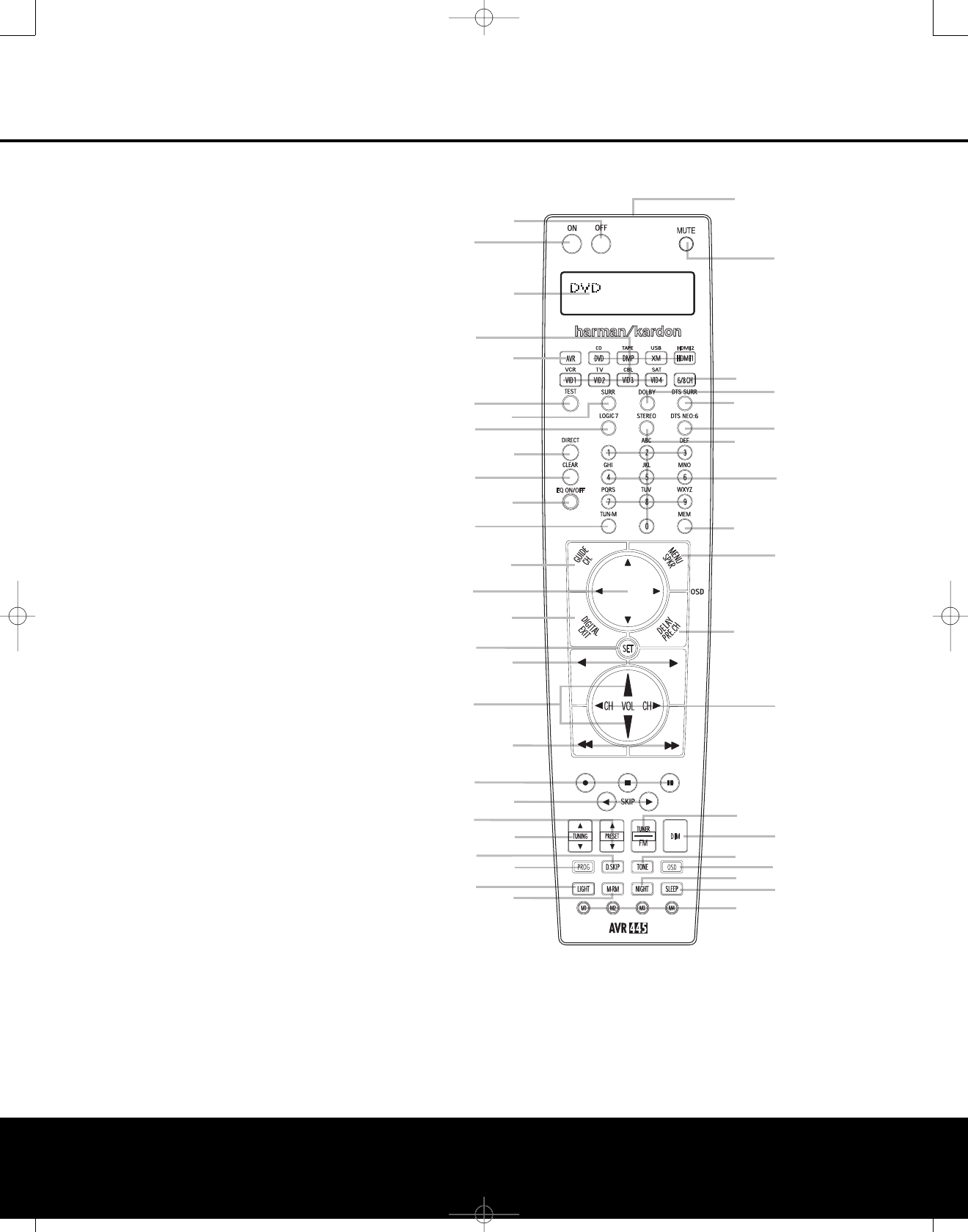
MAIN REMOTE CONTROL FUNCTIONS
MAIN REMOTE CONTROL FUNCTIONS 11
3
D
Y
Z
a
b
G
B
e
f
h
c
I
g
1
2
0
4
56
7
8
9
A
C
E
F
H
J
L
NO
PQ
M
K
S
TU
V
W
R
X
d
i
j
0
Power Off Button
1
Power On Button
2
LCD Information Display
3
Input Selectors
4
AVR Selector
5
Test Button
6
DSP Surround Mode Selector
7
Logic 7 Mode Select Button
8
Direct Button
9
Clear Button
A
EzSet/EQ On/Off Button
B
Tuning Mode Button
mChannel Select Button
nNavigation Button
oDigital Select Button
F
Set Button
G
Transport Play Buttons
H
Volume Up/Down Selectors
I
Transport Fast-Play/Scan Buttons
J
Main Transport Controls
K
Track Skip Up/Down Buttons
L
Preset Up/Down Button
M
Tuning Up/Down Button
N
Disc Skip Button
O
Program Button
P
Light Button
Q
Multiroom Button
R
Macro Buttons
S
Sleep Button
T
Night Mode Button
U
OSD Button
V
Tone Control Button
W
Dim Button
X
Tuner/FM Select Button
Y
Channel Up/Down Selector
Z
Delay Select Button
a
Speaker Select Button
b
Memory Button
cNumeric Keys
dStereo Mode Select Button
eDTS Neo:6 Mode Select Button
fDTS Digital Mode Select Button
g
Dolby Mode Select Button
h
6-Channel/8-Channel Input Select
iMute Button
jLens
NOTES:
•The function names shown here are each button’s feature when used with the AVR 445.
Most buttons have additional functions when used with other devices.When a button is pressed,
the function name will appear in the bottom line of the LCD Information Display c.
•The jack on the upper right side of the remote is reserved for future use. Do not remove the
plug provided or connect any device to the jack.
• To make it easier to follow the instructions that refer to this illustration, a larger copy may be
downloaded from the Product Support section for this product at www.harmankardon.com.
MAIN REMOTE CONTROL FUNCTIONS 11
AVR445 OM 6/23/06 3:13 PM Page 11

MAIN REMOTE CONTROL FUNCTIONS
IMPORTANT NOTE: The AVR 445’s remote may
be programmed to control up to thirteen devices,
including the AVR 445. Before using the remote,
itis important to remember to press the Input
Selector Button
3
that corresponds to the unit
you wish to operate. In addition, the AVR 445’s
remote is shipped from the factory to operate the
AVR 445 and most Harman Kardon brand products.
The remote is also capable of operating a wide variety
of other products using the control codes that are part
of the remote. Before using the remote with other
products, follow the instructions on pages 46–49
toprogram the proper codes for the products in
your system.
It is also important to remember that many of the
buttons on the remote take on different functions,
depending on the product selected using the Input
Selectors d. The descriptions shown here primarily
detail the functions of the remote when it is used to
operate the AVR 445.
aPower Off Button: Press this button to place
the AVR 445 or a selected device in the Standby
mode. Note that this will turnoff the main room
functions, but if the Multiroom system is activated,
it will continue to function.
1
Power On Button: Press this button to turn on
the power to a device selected by first pressing one of
the Input Selectors
3
.
2
LCD Information Display: This two-line screen
displays various information, depending on the com-
mands that have been entered into the remote.
3
Input Selectors: Pressing one of these buttons
will performthree actions at the same time.First, if the
AVR 445 is not turned on, this will power up the unit.
Next, it will select the source shown on the button as
the input to the AVR 445. Finally, it will change the
remote control so that it controls the device selected.
The buttons labeled DVD, DMP, XM and HDMI 1 are
each used to select either of two input sources:
•The first press of the DVD Button selects the compo-
nent connected to the DVD inputs.Asecond press
of this button selects the component connected to
the CD inputs.
• The first press of the button labeled DMP selects
The Bridge as the input. A second press of this button
selects the device connected to the Tape inputs.
•The first press of the XM button selects XM Radio
as the input. Asecond press selects the source
connected to the USB jack as the input.
•The first press of the HDMI 1 button selects the
device that is connected to the HDMI 1 jack.
Asecond press selects the device connected to
the HDMI 2 jack.
In normal operation, the remote will revert to control-
ling the AVR when no button is pressed for 6 seconds.
This allows the remote to automatically return to con-
trol of important functions such as volume, mute and
surround mode selection after you have used the
remote to control another device. If you wish to
change the length of time that the remote operates
another device, or to have the remote remain active
for control of the other device (such as a DVD player
or set-top box) until you manually return control to the
AVR by pressing the AVR Selector
4
, follow the
instructions on page 55.
4
AVR Selector: Pressing this button will switch the
remote so that it will operate the AVR 445’s functions. If
the AVR 445 is in the Standby mode, it will also turn the
AVR 445 on.
5
Test Button: Press this button to begin the
sequence used to manually calibrate the AVR 445’s
output levels. (See page 31 for more information on
manually calibrating the AVR 445.)
gDSP Surround Mode Selector: Press this
button to select one of the DSP surround modes, such
as Hall 1, Hall 2 or Theater. Each press of the button
selects another mode. (See page 58 for more infor-
mation on surround modes.)
7
Logic 7 Mode Select Button: Press this button
to select from among the available Logic 7 surround
modes.(See page 58 for available Logic 7 options.)
8
Direct Button: Press this button when the tuner
is in use to start the sequence for direct entryof a
station’s frequency. After pressing the button, simply
press the proper Numeric Keys
c
to select a
station. (See page 39 for more information on the tuner.)
9
Clear Button: When programming the remote
or using the EzSet feature, press this button to cancel
the current function. When using the remote to enter
frequencies for direct tuner access, press this button
to clear previous entries.
A
EzSet/EQ Button: Press this button to turn the
filters used by EzSet/EQ on or off. This allows you to hear
the difference in system performance when EzSet/EQ is
engaged or out of the signal path.
B
Tuning Mode Button: When using listening to
AM or FM stations, press this button to change the
tuner mode between manual and automatic. When the
button is pressed so that AUTO/STEREO
appears in the Upper Display Line Cand in the
on-screen display,only stations with acceptable signal
quality will be tuned, and the tuner will play FM sta-
tions in stereo, when available. In the AUTO mode,
when the Tuning Up/Down Buttons 3M
π
are pressed, the unit will automatically search for the
next available station with good signal strength. When
this button is pressed so that MANUAL/MONO
appears in the Upper Display Line Cand in the
on-screen display, each press of the Tuning Up/Down
Buttons 3M
π
will move the frequency up or
down in single-step increments. When the FM band is
inuse, pressing the button so that the MANUAL
mode is activated will enable you to tune stations with
weak signals by changing to monaural reception. (See
page 39 for more information on AM/FM tuner opera-
tion.) When listing to XM Radio, press this button to
scroll through the following display options for the
Lower Display Line D: Channel Name ➔Channel
Category ➔Artist ➔Title. (See pages 39–40 for
more information on XM Radio operation.)
CChannel Select Button: This button is used
to start the process of manually setting the AVR 445’s
output levels to an external source. Once this button is
pressed, press the ⁄/¤Navigation Button Dto
select the
channel being adjusted, then press the Set
Button
p
,
followed by the ⁄/¤Navigation Button
Dagain, to change the level setting. (See page 41 for
more information.)
DNavigation Button: This disc-like button is
used to navigate through the on-screen configuration
menus, to scroll through option lists and to select
choices for the various settings such as delay, speakers,
surround modes, digital inputs, etc. To use the button,
simply press it left, right, up or down in the direction
indicated by the ⁄/¤/‹/›icons printed on the
button disc. Depending on the specific task, pressing
the button will either change the menu or a configura-
tion choice, or change the option shown in the on-
screen or front-panel display. The sections in this man-
ual describing the unit’sindividual features and config-
uration options contain specific information on how
navigation controls are used.
E
Digital Select Button: Press this button to
assign
one of the digital inputs abKL to a source.
p
Set Button: This button is used to enter settings
into the AVR 445’s memory. It is also used in the
setup procedures for delay time, speaker configuration
and channel output level adjustment.
G
Transport Play Buttons: These buttons have
no direct function on the AVR 445, but they are used
when the remote is programmed for a compatible
DVD, CD or tape player. Pressing these buttons will
transmit a forward- or reverse-play command,
according to the capabilities of the player being
controlled. In the factory default setting, these buttons
are programmed for Harman Kardon DVD players so
that you may control a compatible player without
having to switch devices.
H
Volume Up/Down Selectors: These controls
share the common disc in the lower section of the
remote. To raise the volume, press the button marked
⁄by pressing toward the top of the remote. To lower
12 MAIN REMOTE CONTROL FUNCTIONS12 MAIN REMOTE CONTROL FUNCTIONS
AVR445 OM 6/23/06 3:13 PM Page 12
the volume, press the button marked ¤by pressing
toward the bottom of the remote. The ‹/›buttons on
the left and right sides of this disc change channels up
ordown when the TV, cable box or satellite Input
Selectors
3
have been pressed.
sTransport Fast-Play/Scan Buttons: These but-
tons have no direct function on the AVR 445, but they
are used when the remote is programmed for a
com-
patible DVD, CD or tape player. Pressing these buttons
will transmit a fast-play forward, fast-play reverse, or fast-
forward or -reverse scan command, according to the
capabilities of the player being controlled. In the factory
default setting, these buttons are preprogrammed
with
the remote codes for Harman Kardon DVD players
so
that you may control a compatible player without hav-
ing to switch devices.
J
Main Transport Controls: These buttons have
no direct function on the AVR 445, but they are used
when the remote is programmed for a compatible
DVD, CD or tape player. Pressing these buttons
will transmit a stop (Í), record (Î), or pause (
±
)
command, according to the capabilities of the player
being controlled. In the factory default setting, these
buttons are programmed with the remote codes for
Harman Kardon DVD players so that you may control
acompatible player without having to switch devices.
K
Track Skip Up/Down Buttons: These buttons
do not have a direct function with the AVR 445, but
when used with a compatibly programmed CD or DVD
changer, they will change the track or chapter currently
being played. In the factory default setting, these buttons
are programmed with the remote codes for Harman Kardon
DVD players so that you may control a compatible player
without having to switch devices.
L
Preset Up/Down Button: When the tuner is in
use, press this button to scroll through the stations
programmed into the AVR 445’s memory.
NOTE: When the AVR 445 is used with The Bridge
(optional) and your iPod, some of the buttons that are
used to control the various transport functions on
source devices are used to control the iPod, and navi-
gate through its menus and content. Consult the
owner’smanual packed with The Bridge for more
information.
MTuning Up/Down Button: Press this button
when the tuner is in use to change the station to one
with a higher or lower frequency, or to change the
XM channel. When the tuner is in the MANUAL/
MONO mode, each tap of the selector will increase
or decrease the frequency by one increment. When
the tuner receives a signal sufficient for adequate
reception, MANUAL TUNED will appear in the
Lower Display Line $and in the on-screen display.
When the tuner is in the AUTO/STEREO mode,
press the button once,and the tuner will scan for a
station with acceptable signal strength. When the next
higher- or lower-frequency station with a strong-
enough signal is tuned, the frequency scan will stop
and the Lower Display Line $and the on-screen
display will indicate AUTO TUNED.When an FM
Stereo station is tuned, the display will read AUTO
ST TUNED. See page 39 for more information
on using the tuner.
N
Disc Skip Button: This button has no direct
function for the AVR 445 but may be used to change
the disc in a CD or DVD changer when the remote is
programmed for that type of device.
O
Program Button: This button is used to begin
the process of programming the remote. Press and hold
this button for 3 seconds to place the remote in the
programming mode. Once the red LED under the Set
Button
p
lights, release the button. You may then
select from the desired option. (See pages 46–56 for
more information on configuring the remote.)
P
Light Button: Press this button to activate the
remote’sbacklight for ease of use in darkened rooms.
Q
Multiroom Button: Press this button to begin
the process of activating the multiroom system or
to change the input or volume level for the second
zone. (See page 44 for additional information on the
multiroom system.)
R
Macro Buttons: Press these buttons to store or
recall a “Macro”, which is a preprogrammed sequence
of commands stored in the remote. (See page 49 for
more information on macros.)
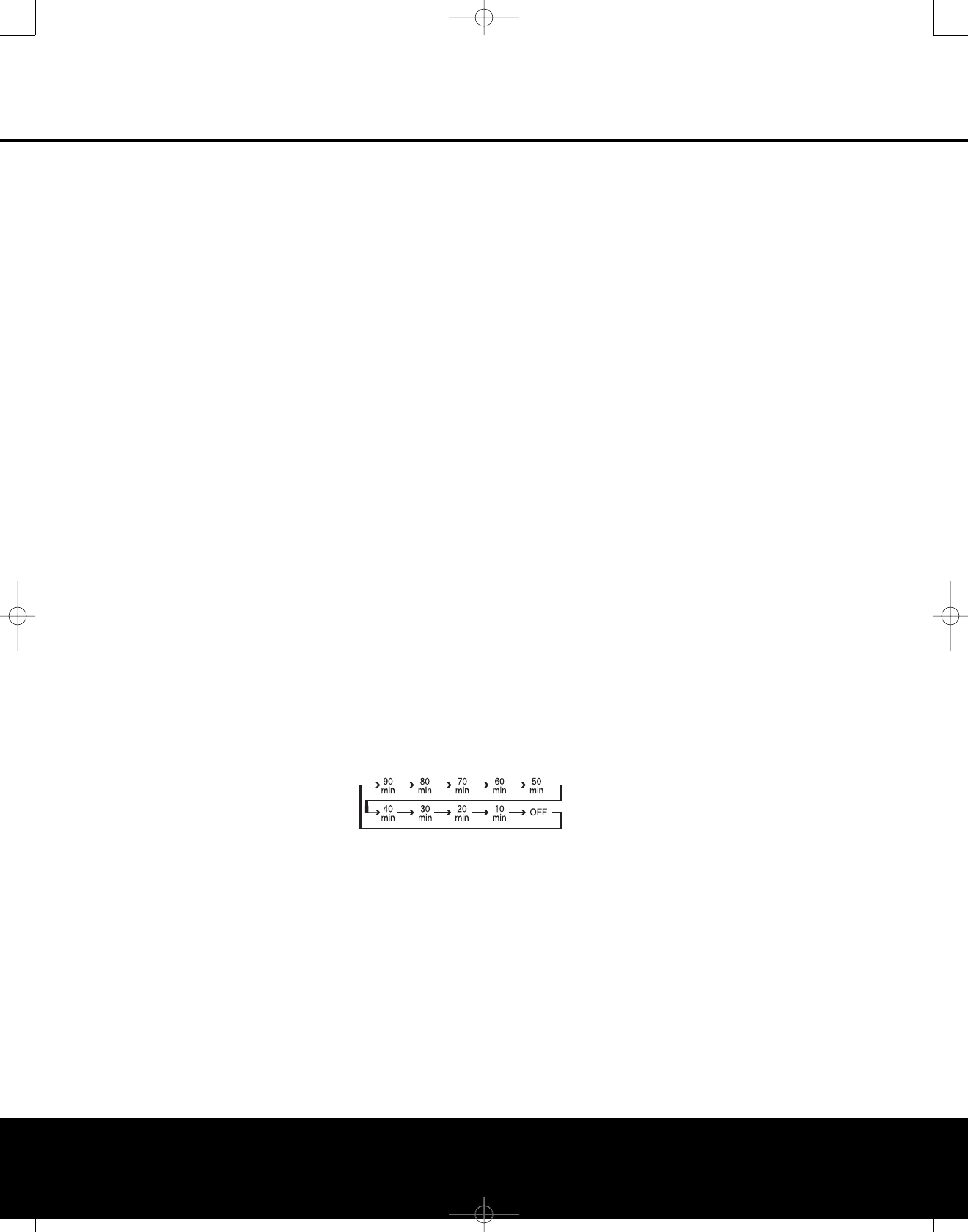
SSleep Button: Press this button to place the unit
in the Sleep mode. After the time shown in the display,
the AVR 445 will automatically go into the Standby
mode.Each press of the button changes the time until
turn-off in the following order:
When the Sleep timer is in use, the front-panel display
indicators will dim to half-brightness.
T
Night Mode Button: Press this button to activate
the Night mode.The Night mode is available in specially
encoded Dolby Digital sources, and it preserves dialogue
(center channel) intelligibility at low volume levels.
U
OSD Button: Press this button to activate or turn
off the On-Screen Display (OSD) system used to set up
or adjust the AVR 445’s parameters.
V
Tone Control Button: This button controls the
tone mode settings, enabling adjustment of the bass
and treble boost/cut. You may also use it to take the
tone controls out of the signal path completely for
“flat” response. The first press of the button displays a
TONE IN message in the on-screen display and
inthe Lower Display Line $.To take the controls
out of the signal path, press either of the ⁄/¤
Navigation Buttons nuntil the display reads
TONE OUT. To change the bass or treble set-tings,
press the button again until the desired option appears
in the Lower Display Line $and in the on-screen
display and then press either of the ⁄/¤Navigation
Buttons nto enter the desired boost or cut setting.
See page 35 for more information on the tone controls.
WDim Button: Press this button to activate the
Dimmer function, which reduces the brightness of the
front-panel display, or turns it off entirely. Press the
button once to change the display to reduce the
brightness by 50%, and press it again within 5 sec-
onds and the main display will go completely dark.
Note that this setting is temporary; regardless of any
changes, the display will always return to full-bright-
ness when the AVR is turned on. The blue illumination
around the Standby/On Switch 1will always
remain at full-brightness, regardless of the setting, to
remind you that the AVR is still turned on. The blue
accent lighting inside the volume control will also
remain at full-brightness when the panel is at 50%,
but go out when the panel lights are fully dimmed.
XTuner/FM Select Button: This button functions
in two ways. Press it up, toward the top of the remote,
to select the tuner as the AVR’s input. The first press
will call up the last-used station (or XM channel).
Subsequent presses will select the last-used FM, AM
and XM Radio station or channel. When the button is
pressed down, toward the bottom of the remote, the
last-tuned FM station is selected as the AVR’s input.
Y
Channel Up/Down Selector: This button has no
function when the AVR is being controlled, but when
programmed for use with a VCR, TV, cable box, satel-
lite receiver or other similar product, it will change the
channel up or down. See pages 46–56 for more
information on programming the remote.
ZDelay Select Button: This button selects
adjustments to the A/V Sync Delay and the individual
channel displays.The first press of the button displays
an A/V SYNC DELAY message in the Lower
Display Line $and in the on-screen display,which
means that you may change the amount of time that
all channels are delayed together behind the video.
This enables you to compensate for the loss of lip
sync that may be caused by digital video processing
in your display or by television stations. To change
the A/V Sync Delay, press the Set Button pwhile
the A/V SYNC DELAY message is visible,
and then use the ⁄/¤Navigation Buttons n
to change the setting so that the sound and the
video image are in sync. To change the delay for
an individual output channel, press the ⁄/¤
Navigation Button nuntil the desired channel
name is shown, and then press the Set Button p.
MAIN REMOTE CONTROL FUNCTIONS
MAIN REMOTE CONTROL FUNCTIONS 13
AVR445 OM 6/23/06 3:13 PM Page 13

Use the ⁄/¤Navigation Buttons ntochange
the delay amount. (See page 30 for more information
on delay options.)
a
Speaker Select Button: Press this button
to begin the process of manually configuring the
AVR 445’s bass management system. Then press
the ⁄/¤Navigation Buttons nto select the
channel you wish to set up. Press the Set Button
pand then select another channel to configure.
When all adjustments have been completed, press
the Set Button ptwice to exit the settings and
return to normal operation. (See page 28 for more
information on manual speaker setup.)
b
Memory Button: Press this button to enter a
radio station in the AVR 445’s preset memory. First,
tune the desired station, and then press this button.
Within 5 seconds of when you see the station’s
frequency flash in the Upper Display Line #and
in the on-screen display, press the numeric keys
for the preset number between 01 and 30 that you
wish to assign to the station. (See page 39 for more
information on the tuner, and see page 40 for infor-
mation on storing XM channel numbers in the preset
memory.)
c
Numeric Keys: These buttons serve as a 10-
button numeric keypad to enter tuner preset positions.
They are also used to select channel numbers when
TV, Cable or SAT has been selected on the remote, or
to select track numbers on a CD, DVD or LD player,
depending on how the remote has been programmed.
These buttons are also used to enter letters and num-
bers when renaming devices in the LCD Information
Display. (See page 53 for more information on renam-
ing devices and keys.)
d
Stereo Mode Select Button: Press this button
to select a stereo listening mode. When the button is
pressed so that SURROUND OFF appears in
the Lower Display Line $,the AVR will operate
in a bypass mode with true, fully analog, two-channel
left/right stereo mode with no surround processing or
bass management, as opposed to other modes where
digital processing is used. When the button is pressed
so that SURROUND OFF appears in the Lower
Display Line $, and both the DSP and Surround
Off
Surround Mode Indicators %are lit, you will enjoy
atwo-channel presentation of the sound, along with
the benefits of bass management. Depending on
whether your system is configured for 5.1 or 6.1/7.1
channels, the next press of the button will cause either
5CH STEREO or 7CH STEREO to
appear, and the stereo signal will be routed to all five
(or seven) speakers. (See page 58 for more informa-
tion on stereo playback modes.)
e
DTS Neo:6 Mode Select Button: Press this
button to select a DTS Neo:6 mode. (See page 58
for the available DTS Neo:6 options.)
f
DTS Digital Mode Select Button: When a
DTS-encoded digital source is playing, each press of
this button will scroll through the available DTS modes.
The specific choice of modes will vary according to
the type of encoding on the disc and your system’s
speaker configuration. When a DTS source is not in
use, this button has no function. (See page 58 for the
available DTS digital options.)
g
Dolby Mode Select Button: This button is used
to select from the available Dolby Surround modes.
Each press of this button selects
aDolby Pro Logic II,
Dolby Pro Logic IIx or Dolby Virtual Speaker mode, as
available for the number of speakers in your system.
When a Dolby Digital-encoded source is in use, the
Dolby Digital mode may also be selected. (See page
58 for the available Dolby surround mode options.)
h
6-Channel/8-Channel Input Select: Press this
button to select the device connected to the 8-Channel
Direct Inputs c.
i
Mute Button: Press this button to momentarily
silence the AVR 445 or TV set being controlled,
depending on which device has been selected.
j
Lens: The infrared emitters behind the plastic
lens at the top of the remote communicate the remote
codes to the AVR 445. Be certain that the lens is not
covered when using the remote, and point the lens
toward the AVR for best results. In learning mode, the
remote receives IR codes to be learned through a
sensor behind the lens.
NOTE: DO NOT remove the rubber plug that covers the
jack on the upper right side of the remote. The jack is
not active and is reserved for future use.
14 MAIN REMOTE CONTROL FUNCTIONS
MAIN REMOTE CONTROL FUNCTIONS
AVR445 OM 6/23/06 3:13 PM Page 14
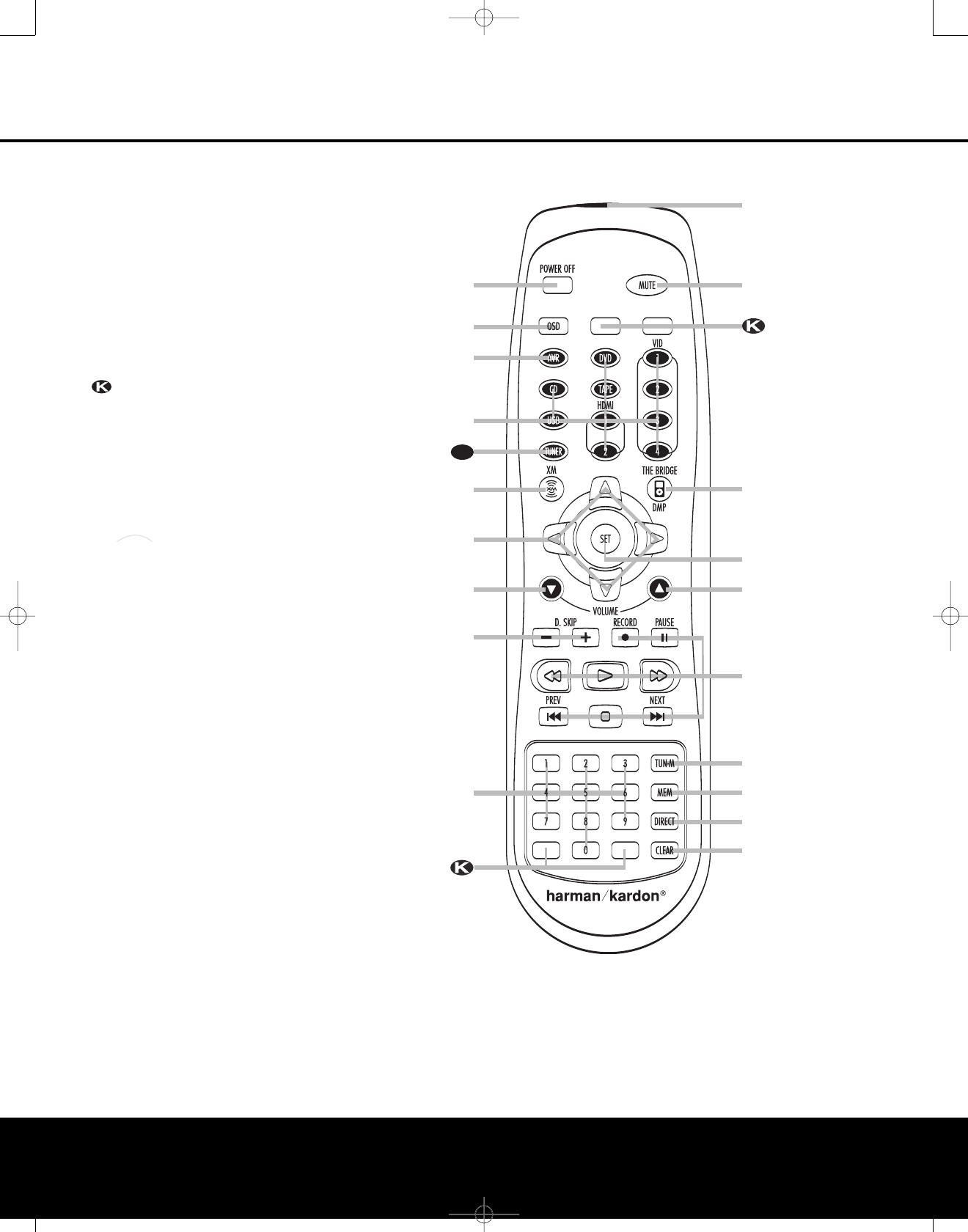
ZR 10 REMOTE CONTROL FUNCTIONS
å
Power Off Button
∫
OSD Button
ç
AVR Selector Button
∂
Input Selectors
≠
Tuner Selector
ƒ
XM Radio Selector
©
Navigation Controls
˙
Volume Up/Down Buttons
î
Disc Skip Buttons
∆
Numeric Keys
Blank Buttons
¬
Clear Button
µ
Direct Button
ñ
Memory Button
ø
Tuning Mode Button
π
Transport Controls
œ
Set Button
®
/DMP Selector
ß
Mute Button
†
IR Transmitter Lens
The
Bridge
TM
E
å
∫
ç
∂
ƒ
©
˙
î
∆
¬
µ
ñ
ø
π
œ
®
ß
†
E
˙
NOTES:
•The ZR 10 remote may be used either in the same room
where the AVR 445 is located or in a separate room
with an optional infrared sensor or A-BUS®product that
is connected to the AVR 445’s Multiroom IR Input
Jack N. When it is used in the same room as the
AVR 445, it will control the functions of the AVR 445
or any compatible Harman Kardon products in that
room. When it is used in a separate room via a sensor
connected to the Multiroom IR Input Jack e, the
buttons for Power, Input Source, Volume and Mute will
control the source and volume for the second zone, as
connected to the Multiroom Audio Output Jacks
ª. (See page 44 for complete information on using
the Multiroom system.)
• To make it easier to follow the instructions that refer to
the controls and connectors in this illustration, alarger
copy may be downloaded from the Product Support
section for this product at www.harmankardon.com.
ZR 10 REMOTE CONTROL FUNCTIONS 15
AVR445 OM 6/23/06 3:13 PM Page 15

16 ZR 10 REMOTE CONTROL FUNCTIONS
å
Power Off Button: When used in the room
where the AVR 445 is located, press this button
to place the unit in Standby. When it is used in a
remote room with a sensor that is connected to the
Multiroom IR Input Jack e,this button turns the
Multiroom system on and off.
∫
OSD Button: Press this button to activate or
turn off the On-Screen Display (OSD) menu system,
used to set up or adjust the AVR 445’s configuration
settings.
ç
AVR Selector Button: Press this button to turn
on the AVR 445. The input in use when the unit was
last on will be selected.
∂
Input Selectors: When the AVR 445 is off,
press one of these buttons to select a specific input
and turn the unit on. When the unit is already in use,
pressing one of these buttons will change the input.
≠
Tuner Selector: Press this button to select the
Tuner as the input source and listen to the tuner band
last used. Press the button again to change between
AM, FM and, if an XM Connect & Play module is con-
nected and activated, XM Radio.
ƒ
XM Radio Selector: Press this button to select
XM Radio as the input source when an XM Connect &
Play module is connected and activated.
©
Navigation Controls: Depending on the menu
or function in use, pressing these buttons will navigate
through menus, scroll through option lists or configura-
tion choices, or move the cursor position. Press the
left, right, up or down button, as appropriate to the
adjustment being made.
˙
Volume Up/Down Buttons: When the ZR 10
remote is used in the room where the AVR 445 is
located, press this button to raise or lower the volume
in that room. When it is used in a remote room with a
sensor that is connected to the Multiroom IR Input
Jack e,this button will raise or lower the volume in
the remote room.
î
Disc Skip Buttons: Press these buttons to
change discs on compatible Harman Kardon CD or
DVD changers or players.
∆
Numeric Keys: Press these buttons to enter a
station’s frequency or an XM Radio channel number
after the Direct Button
µ
is pressed, or when pro-
gramming the tuner memories.These buttons may
also be used for numeric entries when appropriate
with other compatible sources.
Blank Buttons: These buttons are not active.
Pressing them will not change or control any function
on the AVR 445 or other IR devices.
¬
Clear Button: When programming the tuner
memory, press this button to clear the current entry.
µ
Direct Button: Press this button when the tuner
isin use to start the entry of a station’s frequency or
an XM channel number for direct access to that sta-
tion or channel. After pressing this button, press the
appropriate Numeric Keys
∆
.
ñ
Memory Button: Press this button to enter a
station or XM channel number into the AVR 445’s
memory. First, tune to, or select, the desired station
or channel, and then press this button. Within five
seconds, while you see the station or channel flash in
the Upper Display Line Cand in the on-screen
display, press the Numeric Keys
∆
for the preset
number between 01 and 30 that you wish to assign
to the station or channel. (See page 39 for more
information.)
ø
Tuning Mode Button: When listening to AM or
FM stations, press this button to change the tuner
mode between manual and automatic. When the
button is pressed so that AUTO/STEREO
appears in the Upper Display Line Cand in the
on-screen display, only stations with acceptable signal
quality will be tuned, and the tuner will play FM sta-
tions in stereo, when available. In the AUTO mode,
when the Tuning Up/Down Buttons 3M
π
are pressed, the unit will automatically search for the
next available station with good signal strength. When
this button is pressed so that MANUAL/MONO
appears in the Upper Display Line Cand in the
on-screen display, each press of the Tuning Up/Down
Buttons 3M
π
will move the frequency up or
down in single-step increments. When the FM band is
in use, pressing the button so that the MANUAL
mode is activated will enable you to tune stations with
weak signals by changing to monaural reception. (See
page 41 for more information on AM/FM tuner opera-
tion.) When listing to XM Radio,press this button to
scroll through the following display options for the
Lower Display Line D: Channel Name ➛Channel
Category➛Artist ➛Title. (See pages 39–40 for
more information on XM Radio operation.)
π
Transport Controls: Press these buttons to
control the operation of a compatible Harman Kardon
DVD or CD player when the AVR 445 is connected
to the source unit via the IR Input Jack F. When
the AVR 445’s tuner or XM Radio is in use, the
❙‹‹/››❙Prev/Next Buttons
π
are used to
tune up or down through the list of preset stations,
station frequencies or channel numbers.
œ
Set Button: When using the configuration
menus, press this button to enter a setting to the
AVR’s memory.
®
Digital Media Player Selector: When
Harman Kardon’s (optional) is connected to
Digital Media Player (DMP) Input 9and
acompatible iPod is docked in , pressing this
selector will select the iPod as the audio source input
device for the AVR 445. In addition, if a video display
is connected to one of the Video Monitor Outputs
MP, the iPod’s messages will appear on screen,
and in the Upper and Lower Display Lines CD.
The ⁄
/
¤
/
‹
/
›Buttons
©
,the Set Button
œ
and the Transport Controls
π
may be used
to navigate the iPod and to operate many functions.
See page 39, and the manuals for The Bridge and
your iPod for more information.
ß
Mute Button: When the ZR 10 remote is used
in the room where the AVR 445 is located, press this
button to temporarily silence the unit. When it is used
in a remote room with a sensor that is connected
to the Multiroom IR Input Jack e, this button
will temporarily silence the feed to the remote room
only. Press the button again to return to the previous
volume level.
†
IR Transmitter Lens: The infrared code com-
mands from the remote are sent to the AVR from the
components behind this lens. To ensure proper opera-
tion, do not block this area when holding the remote.
The
Bridge
TM
The
Bridge
TM
The
Bridge
TM
The
Bridge
TM
E
ZR 10 REMOTE CONTROL FUNCTIONS
AVR445 OM 6/23/06 3:13 PM Page 16

INSTALLATION AND CONNECTIONS
System Installation
After unpacking the unit, locating it in a place with ade-
quate ventilation and placing it on a solid surface capable
of supporting its weight, you will need to make the con-
nections to your audio and video equipment.
IMPORTANT NOTE: For your personal safety and to
avoid possible damage to your equipment and speakers,
it is always good practice to turn off and unplug the AVR
and ALL source equipment from the AC output before
making any audio or video system connections.
Audio Equipment Connections
We recommend that you use high-quality interconnect
cables when making connections to source equipment
and recorders to preserve the integrity of the signals.
1. Connect the analog output of a CD player to the
CD Audio Inputs 6.
NOTE: If your CD player has both fixed and variable
audio outputs, it is best to use the fixed output unless
you find that the input to the receiver is so low that the
sound is noisy, or so high that it is distorted.
2. Connect the analog Play/Out jacks of a cassette
deck, MD, CD-R or other audio recorder to the
Tape Inputs 4. Connect the analog Record/In
jacks on the recorder to the Tape Outputs 2
on the AVR 445.
3. Connect the output of a digital source such as
aCD or DVD changer or player, a video game, a
digital satellite receiver,an HDTV tuner or digital
cable set-top box or the output of a compatible
computer sound card to the Optical and Coaxial
Digital Audio Inputs abKL.
4. Connect the coaxial or optical Digital Audio Outputs
XY on the rear panel of the AVR 445 to the match-
ing digital input connections on a CD-R, MiniDisc or
other digital recorder.
5. Assemble the AM loop antenna supplied with the
unit so that the tabs at the bottom of the antenna
loop snap into the holes in the base.Connect it to
the AM Antenna Connections i.
6. Connect the supplied FM antenna to the FM
Antenna Jack h.The FM antenna may be
an external roof antenna, an inside powered or
wire-lead antenna or a connection from a cable
TV system. If the antenna or connection uses
300-ohm twin-lead cable, you must use an optional
300-ohm-to-75-ohm adapter to make the
connection.
7. Connect the front, center, surround and surround
back speaker outputs 57DE to the respec-
tive speakers.
To ensure that all the audio signals are carried to your
speakers without loss of clarity or resolution, we sug-
gest that you use high-quality speaker cable. Many
brands of cable are available and the choice of cable
may be influenced by the distance between your
speakers and the receiver, the type of speakers you
use, personal preferences and other factors. Your
dealer or installer is a valuable resource to consult in
selecting the proper cable.
Regardless of the brand of cable selected, werecom-
mend that you use cable
with a gauge of 14 or smaller.
Remember that when specifying cable, the lower the
number, the thicker the cable.
Cable with a gauge of 16 may be used for short runs
of less than 10 feet. We do not recommend that you
use cables with an AWG equivalent of 18 or higher,
due to the power loss and degradation in performance
that will occur.
Cables that are run inside walls should have the appro-
priate markings to indicate listing with UL, CSA or other
appropriate testing agency standards. Questions about
running cables inside walls should be referred to your
installer or a licensed electrician who is familiar with
the NEC and/or the applicable building codes in
your area.
When connecting wires to the speakers,be certain
to observe proper polarity.Note that the positive (+)
terminal of each speaker connection has a specific color
code, as noted on page 8. However, most speakers still
use a red terminal for the positive (+) connection.
Connect the “negative” or “black” wire to the same
terminal on both the receiver and the speaker.
NOTE: While most speaker manufacturers adhere to
an industry convention of using black terminals for
negative and red ones for positive,some may vary
from this configuration. To ensure proper phase and
optimal performance, consult the identification label on
your speaker or the speaker’s manual to verify polarity.
If you do not know the polarity of your speaker, ask
your dealer for advice before proceeding, or consult
the speaker’s manufacturer.
We also recommend that the length of cable used
to connect speaker pairs be identical. For example,
use the same length piece of cable to connect the
front-left and front-right or surround-left and sur-
round-right speakers, even if the speakers are a
different distance from the AVR 445.
8. Connections to a subwoofer are normally made via
aline-level audio connection from the Subwoofer
Output 1to the line-level input of a subwoofer
with a built-in amplifier. When a passive subwoofer
is used, the connection first goes to a power
amplifier, which will be connected to one or more
subwoofer speakers. If you are using a powered
subwoofer that does not have line-level input con-
nections, follow the instructions furnished with the
speaker for connection information.
9. If an external audio source such as a DVD-Audio,
SACD or high-definition optical disc player with 5.1
or7.1 analog audio outputs is part of your system,
connect the outputs of the source to the 8-Channel
Direct Inputs c.
Analog Video Equipment Connections
Analog video components are connected in the same
manner as audio components.Again, the use of high-
quality interconnect cables is recommended to preserve
signal quality.
1. Connect the Video Play/Out jacks of a standard
(composite) video (or S-video outputs of a digital
video) recorder or conventional VCR to the Video 1
Video Inputs Ron the AVR 445. Connect the
Record/In jacks from that device to the Video 1
Video Outputs Son the AVR.
2. Connect the analog Audio Left/Right Play/Out jacks
of the device connected to the Video 1 Inputs to
the Video 1 Audio Inputs don the AVR. Connect
the analog Audio Left/Right Record/In jacks from
that device to the Video 1 Audio Outputs gon
the AVR. If the device has a digital audio output,
connect it to one of the Coaxial aor Optical b
digital audio inputs.
3. Connect the Play/Out jacks of a standard (composite)
video or (S-video outputs of a digital video) playback
source such as a set-top box or video game console
to the Video 2 Video Inputs Tor Video 3 Video
Inputs U. If the device has analog component
video (Y/Pr/Pb) outputs, connect them to one of
the Component Video Inputs O.
4. Connect the analog audio outputs from the source
to the matching Video 2 Audio Inputs eor
Video 3 Audio Inputs f. If the device has a digi-
tal audio output, connect it to one of the Coaxial
aor Optical bdigital audio inputs.
5. If any of the video source devices has analog
component video (Y/Pr/Pb) outputs, but not HDMI,
connect them to Component Video Inputs O.
The chart on page 59 has the default settings for
various source devices, but you may make any
connection and change the configuration setting
using the IN/OUT SETUP menu, as
described on page 23.
6. The default video connection for a DVD player is to
use the Component Video Input 3 Jacks Oon
the AVR, but you may change this assignment in
the IN/OUT SETUP menu (see page 23).
ADVD player’s composite and S-video outputs may
also be connected to the DVD Video Inputs Q.
Only one connection type is required.
INSTALLATION AND CONNECTIONS 17
AVR445 OM 6/23/06 3:13 PM Page 17

18 INSTALLATION AND CONNECTIONS18 INSTALLATION AND CONNECTIONS
INSTALLATION AND CONNECTIONS
7. The default audio connection for a conventional
DVD player is to link the coaxial digital audio output
on the DVD player to the Coaxial 1 Digital Audio
Input a, but you may also make a connection to
either the Coaxial aor Optical bdigital inputs,
or to the Analog DVD Audio Inputs Z. You
may change the assignment in the IN/OUT
SETUP menu as described on page 22, or by
using the front-panel Digital Input Selector F.
8. To use a portable audio/video product such as a
camcorder, media player or digital still camera with
the AVR, or connect a video game console or other
source that may not always be connected to the
AVR, connect the video outputs of the source to the
Video 4 Input/Output Jacks N, behind the
Front-Panel Door 8. If the source has digital
audio outputs, connect them to the Optical 4
Digital Input Kor the Coaxial 4 Digital Input L.
CONNECTION NOTES:
•When making connections to the Component
Video Inputs Oor the Coaxial aor Optical
bdigital audio inputs, it is a good idea to make
note of which jacks are connected to which
source, using the Worksheet in the Appendix. This
will help simplify the configuration process.
• When connecting a source device such as a
cable set-top box where the audio streams may
change between digital and analog as you
change channels, we recommend that you make
both analog and digital connections. The AVR’s
Auto Poll feature will automatically sense when
the digital stream is replaced by an analog output
and switch the input accordingly. (See page 22
for more information on the Auto-Poll feature.)
This dual connection is not required for sources
(such as DVD players or video games) that always
output a digital stream.
9. Connect the AVR to your video display using one of
the following connections, even if you will also use
an HDMI connection:
• If your video display has component video
inputs (Y/Pr/Pb), connect the Component
Video/Monitor Outputs M.
•If your display does not have digital or compo-
nent video inputs, connect the Video Monitor
Output Pon the AVR to the matching input on
your display. Only one connection is needed, and
S-video is the higher quality signal.
HDMI Connections
HDMI™is the abbreviation for High-Definition Multimedia
Interface, which is quickly becoming the standard for
connections between high-definition video/audio source
products and displays. HDMI is a digital connection, elimi-
nating the need to convert signals back and forth from
digital to analog.
Some source or display components in your system
may use DVI (Digital Video Interface) for digital video
connections. DVI carries the same digital video signals
as HDMI but uses a larger connector and does not
transport audio or control signals. In most cases, you
may mix and match DVI and HDMI digital video con-
nections by using optional connector adapters. Note,
however, that some DVI-equipped video displays are
not compatible with the HDCP copy protection coding
that is increasingly carried with signals connected
via HDMI. If you have an HDMI source and a DVI-
equipped display, you may occasionally be unable to
view a program if the display does not include HDCP.
This is not the fault of the AVR or your source; it sim-
ply indicates that the video display is not compatible.
The AVR 445 is equipped for HDMI switching, which
means that it is able to select either of the two HDMI
inputs as the source that feeds your system’s video
display. This preserves the digital signal in its original
formby passing it directly through from source to dis-
play. However, this also means that the AVR does not
have access to the signal and thus it is not able to add
menus or on-screen messages to HDMI signals, or to
process the audio that may be part of the signal in an
HDMI connection.
Therefore, the following connections are required when
the AVR 445 is used with HDMI sources:
• Connect the HDMI output of a source to either of
the HDMI Inputs L.
•Connect the HDMI Output Kof the AVR to an
HDMI input on your display.
• Connect either an optical or coaxial digital audio
output from the source to the AVR. The default
connections are Optical 3 bfor a source con-
nected to HDMI 1 Land Coaxial 3 afor a
source connected to HDMI 2 L. You may use
any digital or analog audio source in conjunction
with the HDMI inputs, but if it varies from the
default you must make a change to the input’s
setting, as shown on page 22.
•Even when HDMI inputs are used, it is important to
make sure that a component, S-video or compos-
ite video connection is made between the AVR and
your display. This is needed to view both the setup
menus and on-screen messages, and to view other
(non-HDMI) video sources. The AVR 445 does not
convert analog video signals to HDMI.
System and Power Connections
The AVR 445 is designed for flexible use with multiroom
systems, external control components and power amplifiers.
Main Room Remote Control Extension
If the receiver is placed behind a solid or smoked-
glass cabinet door, the obstruction may prevent the
remote sensor from receiving commands.In this
event, an optional remote sensor may be used.
Connect the output of the remote sensor to the
IR Input fl.
If other components are also prevented from receiving
remote commands, only one sensor is needed. Simply
use this unit’s sensor or a remote eye by running a
connection from the IR Output ‹to the Remote IR
Input jack on Harman Kardon or other compatible
equipment.
If other Harman Kardon-compatible source equipment
is part of the main room installation, the IR
Output
Jack ‹on the rear panel should be connected
to the
IRIN jack on source equipment. This enables the remote
room location to control source equipment functions.
When a remote IR sensor is used to control non-
Harman Kardon source equipment, we recommend
that you make a hard-wire connection or use an
optional, external IR “blaster” connected to the Full
Carrier IR Output B. If you are in doubt as to which
IR Output jack to use for the equipment in your sys-
tem, contact your dealer or installer, or the manufac-
turer’s support site and ask whether the unit to be
controlled uses “full carrier” IR commands. When “full
carrier” commands are used, make the connection to
the Full Carrier IR Output ¤. Otherwise, make the
connection to the IR Output ‹.
NOTE: All remotely controlled components must be
linked together in a “daisy chain.” Connect the IR OUT
jack of one unit to the IR IN of the next to establish
this chain.
Multiroom Audio Connections
The AVR 445 is equipped with multizone capabilities
that allow it to send a separate audio source to the
remote zone from the one selected for use in the
main room.
Depending on your system’s requirements, three
options are available for audio connection:
Option 1: Use high-quality, shielded audio intercon-
nect cable from the AVR 445’s location to the remote
room. In the remote room, connect the interconnect
cable to a stereo power amplifier. The amplifier will be
connected to the room’s speakers. At the AVR 445,
plug the audio interconnect cables into the Multiroom
Audio Outputs 8on the AVR 445’srear panel.
Option 2: Connect the Multiroom Audio Outputs
8on the AVR 445 to the inputs of an optional stereo
power amplifier. Run high-quality speaker wire from
the amplifier to the speakers in the remote room.
Option 3: Taking advantage of the AVR 445’s built-in
seven-channel amplifier, it is possible to use two of the
amplifier channels to power speakers in the remote
room. When using this option, you will not be able to
use the full 7.1-channel capabilities of the AVR 445 in
the main listening room, but you will be able to add
another listening room without external power ampli-
fiers. To use the internal amplifiers to power a remote
INSTALLATION AND CONNECTIONS
AVR445 OM 6/23/06 3:13 PM Page 18

INSTALLATION AND CONNECTIONS
zone, connect the speakers for the remote room loca-
tion to the Surround Back/Multiroom Speaker
Outputs fi. Before using the remote room, you will
need to configure the amplifiers for surround operation
bychanging a setting in the MULTIROOM
menu, following the instructions shown on page 44.
NOTE: For all options, you may connect an optional
IRsensor in the remote room to the AVR 445 via an
appropriate cable. Connect the sensor’s cable to the
Multiroom IR Input eon the AVR 445 and use
the ZR 10 remote to control the room volume. You may
install an optional volume control between the output of
the amplifiers and the speakers in options 1 and 2.
A-BUS®Installation Connections
The AVR 445 is among the few receivers available
that offer built-in A-BUS/READY operation. When used
with an optional A-BUS product, you have all the ben-
efits of remote zone operation without the need for an
external power amplifier.
To use the AVR 445 with an approved A-BUS prod-
uct, simply connect it to the AVR 445 using standard
Category 5 wiring that is properly rated for the specific
in-wall installation. Terminate the wiring at the receiver
end to a standard RJ-45 connector in compliance
with the instructions furnished with the A-BUS product.
No further installation or adjustment is needed, as the
A-BUS jack on the AVR 445 routes the signals to their
proper destination for power, signal source and control.
The output fed to the A-BUS jack is determined by the
AVR 445’smultiroom system and menus.
RS-232 Connections
The AVR 445 is equipped with an RS-232 Serial
Connection Port athat may be connected to a
compatible,optional, external computer, keypad or
control system for bidirectional communications that
enable the external system to control the AVR, and for
the AVR to report status and handshake data back to
the controller.Use of the RS-232 port for this type of
control requires specific technical knowledge, and we
recommend that any connection and programming for
control be made by a trained installer or technician
familiar with the equipment being used.
The physical connection to the AVR 445’sRS-232
port is a standard D-SUB 9 connection, but to ensure
compatible and proper operation, specific software
commands and pin wiring schemes may be required.
USB Connections
The AVR 445 is one of the few A/V receivers to offer
aUSB connection that may be used for both playback
of compatible audio content from a computer and for
loading of system updates (when available).
The physical connection between a computer and the
AVR is a simple one, requiring only a cable with a USB
“A” type connector on one side and a USB “Mini B” on
the other.
Connect the larger, “A” connector on the cable to your
computer or a USB hub and the end with the “Mini”
USB connector to the USB Port Won the AVR’s
rear panel.
NOTES ON USB:
•The USB port on the AVR 445 is to be used only
for connection to a computer or a hub connected
directly to a computer. DO NOT connect it to other
devices such as portable audio players, card readers,
USB memory storage devices, external hard drives,
USB accessories, digital cameras or cellular phones.
Connection to these devices may cause damage to
the device and/or the AVR that is not covered by
the AVR’s warranty.
•The AVR 445’s USB connection may only be used
for audio playback and system upgrades. It may not
be used for other purposes, such as system control,
video or still-image playback.
Trigger Connection
The AVR 445 is equipped with a low-voltage trigger
that may be used to control a wide variety of compati-
ble, optional devices that respond to voltage actuation
commands. This includes external audio power amplifiers,
video screens, motorized blinds and other compatible
products in a home theater or automation system.
Due to the complexity of interfacing with power-
controlled devices, we strongly recommend that
they be installed by a qualified professional.
The Trigger Output Hdelivers 6 volts DC when
activated, and removes the voltage when the AVR
is turned off. The connection is a 3.5mm mono mini
plug with the signal on the center pin (“tip”) and the
outer shaft (“ring”) acting as the negative or ground
connection.
The Trigger Output His for use with devices such as
power amplifiers that you wish to activate whenever the
AVR is turned on, regardless of the input selected.
After checking for voltage, current and polarity com-
patibility between the device being controlled and the
AVR, simply connect one end of the trigger cable to
the device being controlled and the other end to the
Trigger Output Hon the AVR.
IMPORTANT NOTE ON THE TRIGGER CONNECTION:
The current draw from the trigger jack cannot
exceed 1.0mA.
XM Radio Connections
XM Radio is a satellite-delivered, subscription-based,
programming service that provides a wide range of
music, sports, news and information programming with
digital audio quality. The AVR 445 is XM Connect &
Play-ready,which means that you can easily add the
XM service to your home audio system by purchasing
an XM antenna module,activating an account with XM
and then making a simple, single-cable connection to
your AVR.
To purchase an XM antenna module, consult your
dealer, or contact XM Radio at www.xmradio.com.
After following the instructions packed with the mod-
ule, place the XM antenna near a south-facing window
and run the cable to the AVR. Connect the plug at the
end of the cable to the XMReady Input V.Once
the connection is made, follow the instructions on page
39 for more information on listening to XM Radio.
NOTES on XM Radio:
•XM Radio requires the purchase of additional,
optional hardware and a separate subscription to
the XM service.
•XM Radio is available only in the continental United
States and Canada. It is not available in Alaska
or Hawaii.
•XM reception requires that the antenna be able to
“see” the XM satellites or receive a signal from one
of the XM ground-based repeaters. Depending on
your installation and location, XM service may not
be available in some areas.
AC Power Connections
This unit is equipped with an accessory AC outlet
that may be used to power accessorydevices, but it
should not be used with high-current draw equipment
such as power amplifiers. The total power draw may
not exceed 100 watts.
This Switched AC Accessory Outlet ‡is powered
only when the unit is on. This is recommended only
for devices that have a mechanical power switch that
may be left in the “ON” position.
NOTE: Many audio and video products go into a
Standby mode when they are used with switched out-
lets. This type of product may not operate properly
when used with the switched outlet.
The AVR 445 features a removable power cord
that allows wires to be run in advance to a complex
installation so that the unit itself need not be installed
until it is ready for connection. When all needed
connections have been made, connect the AC
power cord to the AC Power Cord Jack ·.
The AVR 445 draws significantly more current than
other household devices, such as computers, that use
removable power cords. For that reason, it is important
that only the cord supplied with the unit (or a direct
replacement of identical capacity) be used.
Once the power cord is connected, you are almost
ready to enjoy the AVR 445’s incredible power
and fidelity!
INSTALLATION AND CONNECTIONS 19
AVR445 OM 6/23/06 3:13 PM Page 19
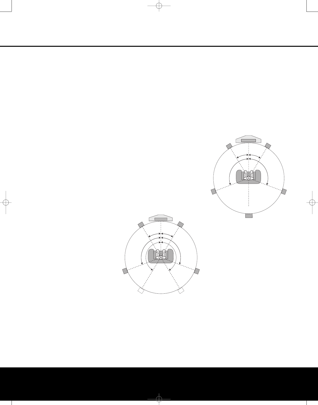
When all audio, video and system connections have
been made, the final steps before listening to your new
AVR are to make the configuration adjustments that
tailor the unit to the other components in your system,
aswell as accommodate your personal listening pref-
erences. A few minutes spent to correctly calibrate and
configure your system will greatly add to your listening
pleasure.
Speaker Selection and Placement
While the most seamless surround sound reproduction
comes from the use of speakers with identical or care-
fully matched driver elements at each position, no
matter which brand or type of speakers you prefer, it
is always best to use the same model or series for
the left front, center and right front speakers. Similarly,
it is also desirable to use the same model or series
for the surround speakers. This ensures that the sound-
stage will be relatively seamless when a sound moves
from one side of the room to the other.
Speaker Placement
Once you have selected your speakers, it is important
that they be placed in positions that enable them to do
the best job of reproducing the sound as it was meant
to be heard, regardless of the program content. The
placement of speakers can have a noticeable impact
on the accuracy of the surround process, particularly in
multichannel systems.
When placing your speakers in a listening room, pic-
ture an imaginary circle starting at the center of your
video screen that arcs around the room with the prime
listening position, or “sweet spot,” at the center of the
circle. Depending on the number of speakers in your
system, there is a recommended placement along the
circle for each speaker, though the specific construc-
tion of your room, taking into account the available
walls, bookcases, or floor space at which the speakers
may be placed will obviously have some impact on
where the speakers are ultimately located. As a general
rule, try to place all speakers so that they are posi-
tioned at the same height as your ears when you are
seated at the prime listening position.
Use the following suggestions as a guide,and make
the changes needed to fit the speakers to your room.
Don’t be afraid to experiment a bit until you find the
right combination of locations that works for you. At
the end of the day, there is no real “right” or “wrong”
place to put the speakers; work to optimize their loca-
tions so that audio moves across the front of the room
smoothly, without seeming to jump from one speaker
to another.
Front Left/Right Speakers
The recommended placement for front left/right
speakers is at the 30-degree position with reference
to the center channel speaker. The distance between
them should be about the same as the distance from the
center channel speaker to the prime listening position.
Although the natural tendency is to place the speakers
so they are parallel to the wall behind them, and thus
in line with the video screen, the preferred placement
isto angle the speakers slightly (“toe in”) so that they
point at the prime listening position.
Center Channel Speaker
The ideal location for the center channel speaker is at
“0 degrees” in our circle, directly in front of the prime
listening position. Place the center channel speaker as
close to the top (or bottom) of the video screen as
possible so that when you position the front left/right
speakers the tweeters of all three front channel speak-
ers are within 24" of one another.
Surround Speakers for 5.1 Systems
In a 5.1 surround system, an additional pair of
left/right speakers is added. Although many believe
that these speakers should be placed at the rear of
the room, the preferred position for them is at the
sides of the room, with rear placement a second
option when room conditions prevent the use of side-
mounted surround speakers.
When side-wall placement is possible, place the
left/right surround speakers at a point that is 110
degrees along our circle from the center of the video
screen. This translates to placing them to the side and
slightly behind your preferred listening position. If pos-
sible, angle the speakers in slightly so that they are
pointing toward the listener’s ears.
5.1 Placement Diagram
If it is not possible to place the surround speakers at
the sides of the room, the alternate position is at the
back of the room, at a spot that is about 150 degrees
around our circle from the center of the video screen.
Another way to spot the optimal, alternate rear-wall
mounting position is to place the left surround speaker
on the back wall so that it points directly at the front
right speaker, and to have the right surround speaker
point directly at the front left speaker.If possible,
aim the surround speakers so that they point inward,
toward the listening area, rather than perpendicular
to the walls.
Surround Speakers for 6.1 Systems
A6.1 surround system adds an additional speaker in
the center back surround position. We do not recom-
mend this configuration, as it will not deliver a full sur-
round sound field when any 7.1-channel mode is
used, since some signals will be sent to an output
(either left or right) where no speaker is present.
If a 6.1 system is to be used, first place the speakers
for a 5.1 system, and place the “sixth” speaker at the
center of the back of the room, pointing directly
toward the front center channel speaker.
6.1 Placement Diagram
Do not connect the center back surround speaker at
this time, as you must first run EzSet/EQ as shown on
page 26 so that the system configures the five main
channel speakers only. After completing the EzSet/EQ
process, connect the center surround back speaker to
one of the Surround Back Speaker Outputs E
and manually configure the system for surround back
speakers, as shown on pages 29–30. DO NOT run
EzSet/EQ
with only a single surround back speaker
connected, as a failure message will result.
We recommend that you consider adding a second
surround back speaker for a full 7.1 system, as soon
as possible.
Surround Speakers for 7.1 Systems
For the ultimate home theater experience,a7.1
surround system uses both traditional surround
left/right channels and a surround back left/right
speaker pair. In a 7.1 system, the front left/center/right
speakers remain in the same place as they would be
for a 5.1 or 6.1 system, but due to the number of
speakers involved, the placement of the surround
speakers is different.
In a 7.1 system, you should place the main surround
left/right speakers at the 90-degree point on our cir-
Center Speaker
Video Screen
Front Right
Speaker
Front Left
Speaker
Side Surround
Left Speaker
Side Surround
Right Speaker
Back Surround
Speaker
Listening Position
110° 110°
30° 30°
Center Speaker
Video Screen
Front Right
Speaker
Front Left
Speaker
Side Surround
Left Speaker
Alternate placement
for Side Surround
Left Speaker
Side Surround
Right Speaker
Alternate placement
for Side Surround
Right Speaker
110 °
150°
110 °
150°
30° 30°
20 SYSTEM CONFIGURATION
SYSTEM CONFIGURATION
AVR445 OM 6/23/06 3:13 PM Page 20
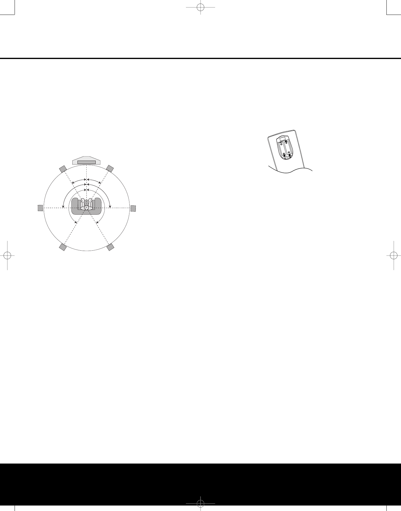
SYSTEM CONFIGURATION
SYSTEM CONFIGURATION 21
cle. A good way to visualize proper surround speaker
positioning for 7.1 is to place the speakers directly to
the left and right of the ears of someone sitting in the
prime listening spot. The two speakers should ideally
face toward each other.
The additional Surround Back Left/Right speakers are
placed at about 150 degrees on the circle, pointing
inward, toward the listening area. The easiest way to
visualize the placement of these speakers is to place
the surround back left speaker directly opposite the
right front speaker and to place the surround back left
speaker directly opposite the left front speaker.
7.1 Placement Diagram
Subwoofer Placement
Since subwoofers produce nondirectional sound, they
may be placed almost anywhere in a room. Actual
placement should be based on room size and shape
and the type of subwoofer used. One method of find-
ing the optimal location for a subwoofer is to begin by
placing it in the front of the room, about six inches
from a wall, or near the front corner of the room.
Another method is to temporarily place the subwoofer
at your normal listening position, and then walk
around the room until you find a spot where the sub-
woofer sounds best. Place the subwoofer in that spot.
You should also follow the instructions of the subwoofer’s
manufacturer,or you may wish to experiment with
the best location for a subwoofer in your particular
listening room.
For more information on subwoofer placement, as well
as a variety of topics relating to audio and home the-
ater, visit the Technology section of our Web site at
www.harmankardon.com. Links are provided there to
informative white papers written by the acoustic and
electronics experts at Harman Kardon and at our par-
ent company, Harman International Industries, Inc.
NOTES ON SPEAKER PLACEMENT:
1. The limitations of your listening room, including the
placement of walls and furniture, may make it diffi-
cult to follow the speaker placement suggestions
shown above. Depending on the specific layout of
the room, here are some ways to compensate for
unusual conditions:
• Try to follow the suggested placement, but move
the speakers within a few feet from the preferred
locations.
•Regardless of where they are placed, always try
to make certain that the main surround speakers
are the same distance from the front speakers.
(For example, try not to have the right surround
speaker further back into the room than the left
surround speaker.)
• If it is not possible to wall-mount or place speak-
ers on a shelf, consider the use of optional floor
stands, available for many speakers.
2. When using ceiling-mounted in-wall speakers, fol-
low the same guidelines shown for conventional
floorstanding or shelf-mounted speakers.
System Setup
Once the speakers have been placed in the room and
connected, the remaining steps in the setup process
are to assign input and output connections, make any
video or audio adjustments, select a surround mode,
program the AVR 445’sbass management system for
the type of speakers used in your system, calibrate
the output levels and set the delay times used by the
surround sound processor.
Although it is necessary to assign input/output settings
and surround mode choices manually,we recommend
that you take advantage of the power and precision of
EzSet/EQ to automatically select and enter the settings
for all other audio parameters. This will not only
save
you time; it will ensure that your room is calibrated
and
equalized with an accuracy not possible when these
settings are made manually.
You are now ready to power up the AVR 445 to begin
these final adjustments.
1. Make certain that the AC power cord is firmly
inserted into the AC Power Cord Socket I
and plug the cord into an unswitched AC outlet.
Tomaintain the unit’ssafety rating, DO NOT
substitute the power cord for one with lower
current capacity.
2. Press the Main Power Switch Alocated
behind the Front-Panel Control Door 9in
until it latches and the word “OFF” on the top of
the switch disappears inside the front panel. Note
that the illumination around the Standby/On
Switch 1will turn amber, indicating that the
unit is in the Standby mode.
3. Carefully remove the protective plastic film from
the front-panel lens. If left in place, the film will
prevent proper operation of the remote control.
4. Install the four supplied AAA batteries in the
main remote as shown. Be certain to follow the
(+) and (–) polarity indicators that are in the
battery compartment. (The ZR10 remote
requires two AAA batteries.)
5. Turn the AVR 445 on either by pressing the
Standby/On Switch 1on the front panel, or
via the remote by pressing the Power On Button
b, the AVR Selector e
ç
or any of the
Input Selectors
3Xh
ç∂ƒ
≠®
on the remote. The lighting around the
Standby/On Switch 1will turn blue to confirm
that the unit is on.
Using the On-Screen Display
When making the following adjustments, you may
find it easier to use the AVR 445’s on-screen display
system. These easy-to-read displays give you a clear
picture of the current status of the unit and make it
easy to see which speaker, delay, input or digital
selection you are making.
Toview the on-screen menus, make certain that you
have made a video connection to the appropriate
matching input of your TV or projector. In order to view
the AVR 445’s displays, the correct video source must
be selected on the video display. On-screen menus
may be viewed through component, S-video or com-
posite video connections, but they are not available
when an HDMI source is selected as the input or
through the HDMI Output K.
IMPORTANT NOTE: When viewing the on-screen
menus using a CRT-based projector, plasma display or
direct-view CRT monitor or television, it is important that
they not be left on for an extended period of time.The
constant display of a static image such as these menus
may cause the image to be permanently “burned into”
the projection tubes, plasma screen or CRT display.
This type of damage is not covered by the AVR 445
warranty and may not be covered by the projector/TV
set’s warranty.
The AVR 445 has two on-screen display modes,
“Semi-OSD” and “Full-OSD.” When making configura-
tion adjustments,it is recommended that the full-OSD
mode be used. This will place an easily viewed list of
the available options on the screen.
Center Speaker
Video Screen
Front Right
Speaker
Front Left
Speaker
Side Surround
Left Speaker
Back Surround
Left Speaker
Side Surround
Right Speaker
Back Surround
Right Speaker
90°
150°
90°
150°
30° 30°
AVR445 OM 6/23/06 3:13 PM Page 21
Making Configuration Adjustments
The full-OSD system is available by pressing the
OSD Button U
∫
. When this button is pressed,
the MASTER MENU (Figure 1) will appear, and
adjustments are made from the individual menus.
Figure 1
The semi-OSD system is also available, allowing you
to make adjustments directly, by pressing the appro-
priate buttons on the front panel or remote control for
the specific parameter to be adjusted. For example, to
change the digital input for any of the sources, press
the Digital Select Button oand then press the
⁄/¤Navigation Button
n
to scroll through the
list of options as they appear in the on-screen display
or in the Lower Display Line $.
Semi-OSD messages are available only when a 480i
input source is being viewed. They are not available
when a 480p, 720p or 1080i source or an HDMI
input is selected.
To use the full-OSD menu system, press the OSD
Button U
∫
.When the menu is on the screen,
press
the ⁄/¤Navigation Button n
©
until the
on-screen
➔cursor is next to the item you wish to
adjust, and then press the Set Button p
œ
to
adjust that item. The menus will remain on the screen
for 20 seconds, and then they will “time-out” and dis-
appear from
the screen. The time-out may be
increased to as much as 50 seconds by going to the
ADVANCED menu, and changing the item titled
FULL OSD TIME OUT.
When the full-OSD system is in use,the menu selec-
tions are not shown in the Upper or Lower Display
Lines #$. When the full-OSD menu system is
used, OSD ON will appear in the Upper Display
Line #to remind you that a video display must be
used. When the semi-OSD system is used in conjunc-
tion with the discrete configuration buttons, the on-
screen display will show two lines of text with the cur-
rent menu selection. That selection will also be shown
in the Upper or Lower Display Lines #$,
depending on which parameter is being adjusted.
Setting the System Configuration Memory
The AVR 445 features an advanced memory system
that enables you to establish different configurations
for the component video assignment, digital input and
surround mode and other settings for each input
source. This flexibility enables you to customize the
way in which you listen to each source and have the
AVR 445 memorize those settings. Once these set-
tings are made, they will automatically be recalled
whenever you select that input.
To simplify initial configuration and operation, the
AVR 445 has been preconfigured with input settings
that are typical for home theater systems. These set-
tings are detailed in the worksheets in the Appendix.
Before adjusting the input settings, it is a good idea to
compare your input connections to the defaults so that
you may see where changes need to be made.
Before using the unit, you may want to change the
settings for some inputs so that they are properly
configured to reflect the use of digital or analog
inputs, the type of video display and speakers
installed, and the surround mode specifics of your
home theater system.
In/Out Setup
The first step is to configure each input source. When
an input is selected,
the settings will “attach” them-
selves to that input and be stored in a nonvolatile
memory. Once made, the selection of an input will
automatically recall those settings. For that reason, the
procedures described below must be repeated for
each input source so that you have the opportunity
to customize each source to your specific listening
requirements. However, once done, they need not
be changed again unless your system components
have changed.
When using the full-OSD system to make the setup
adjustments, press the OSD Button U
∫
once
so that the MASTER MENU (Figure 1) appears.
The cursor will be next to the IN/OUT SETUP
line. Press the Set Button p
œ
and the first page
of the IN/OUT SETUP menu (Figure 2) will
appear on the screen. Press the ‹/›Navigation
Button D
©
until the desired input name appears
in the highlighted video, as well as being indicated in
the front-panel Input Indicators !.
Figure 2
When any input other than the tuner, 8-channel inputs
or the USB input, is selected as the source, you have
the option of renaming the input as it appears in the
on-screen and front-panel messages. This is helpful if
you wish to associate a specific product brand name
with the input, or to simply enter any name that will
help you to remember which source is being selected.
To change the input name, press the ⁄/¤Navigation
Buttons D
©
on the remote so that the cursor
ispointing to TITLE.Next, press and hold the
Set Button p
œ
for a few seconds until a flashing
box appears to the right of the colon. Immediately
release the Set Button p
œ
, as you are now
ready to enter the device name.
Press the ⁄/¤Navigation Buttons D
©
and
note that alphanumeric characters will appear with
the start of the alphabet in capital letters, followed by
the lowercase letters, and then numbers and symbols.
When you press the ¤Navigation Button D
©
, the symbols and numbers will appear first,
followed by a reverse list of the alphabet in lowercase
letters. Press the button either way until the first
letter of the desired name appears. If you wish to
enter a blank space as the first character, press the
›Navigation Button D
©
.
When the desired character appears, press the ›
Navigation Button D
©
and repeat the process
for the next letter, and continue until the desired name
is entered, up to a maximum of 14 characters. Press
the Set Button p
œ
to enter the input name into
the system memory and to proceed with the configu-
ration process.
After entering the input title, press the ⁄/¤
Navigation Buttons D
©
to move to the
next line.
The audio input defaults are shown in the table in the
Appendix. If your system configuration follows the
default table,no changes are needed and you may
press the ⁄/¤Navigation Buttons D
©
to
move to the next line.
With the cursor pointing to AUDIO IN-PORT,
press the ‹/›Navigation Buttons D
©
to
change the default to a different audio input connection.
When the name of the desired input appears, press
the ⁄/¤Navigation Buttons D
©
to move
to the next line.
In normal operation, when a digital audio stream is
interrupted, the unit will automatically switch to the
analog inputs associated with that source. This is par-
ticularly useful with cable set-top boxes where the
input is normally digital, but occasionally changes to
analog. If you wish to configure an input so that the
auto-poll circuit is turned off, while the on-screen cur-
sor is pointing to the AUDIO AUTO POLL
line, simply press the ‹/›Navigation Buttons
D
©
so that OFF (rather than ON)is highlighted.
*IN/OUT SETUP *
SOURCE: VIDEO 1
TITLE:
AUDIO IN-PORT: ANALOG
AUDIO AUTO POLL: OFF ON
VIDEO IN PORT: AUTO
COMPONENT INPUT: COMP 1
VIDEO PROCESS: V CONVER
A/V SYNC DELAY: 0 mS
MASTER MENU PAGE 2
→→
** MASTER MENU **
IN/OUT SETUP
AUDIO ADJUST
SURROUND SETUP
EZSET/EQ
MULTI-ROOM
ADVANCED
→→
SYSTEM CONFIGURATION
22 SYSTEM CONFIGURATION22 SYSTEM CONFIGURATION
AVR445 OM 6/23/06 3:13 PM Page 22

SYSTEM CONFIGURATION 23
SYSTEM CONFIGURATION
When the desired auto-poll setting is entered, press
the ⁄/¤Navigation Button D
©
to move to
the next line.
When the cursor is at the VIDEO IN-PORT
line, you are able to select an alternative to the default
input setting for the video input associated with any
source except HDMI 1 and HDMI 2. For the Video 1
and Video 4 inputs, the factory default of AUTO will
select either composite or S-video, depending on
which has an active signal. For the Video 2, Video 3
and DVD inputs, the AUTO setting will normally
select the default component input, but if it is not
in use, the system will revert to a composite or
S-video output if either one is active. You may set
COMPONENT INPUT to OFF if you
aren’t using component video, and the AVR will not
select the component video inputs.
To have the AVR always look to a specific source con-
nection when an input is selected, make certain that
the on-screen cursor is pointing to the VIDEO
IN-PORT line; then press the ‹/›Navigation
Buttons D
©
until the name of the desired input
appears. Note that this setting is not available when
the HDMI inputs are selected. The choice of available
inputs may vary according to whether an audio-only
source (such as the tuner, CD or tape) or an audio/
video source (such as Video 1–Video 4 or DVD) is
selected.
When the desired video input setting has been made,
press the ⁄/¤Navigation Buttons D
©
to
move to the next line.
If your system includes any sources that are equipped
with Y/Pr/Pb component video outputs, the AVR 445
is able to switch them to send the proper signals to
your video display. Each of the Component Video
Inputs Ois assigned to a default source,as shown
in the table in the Appendix, but if you have connected
your system differently than the factory settings, you
may select any of the three inputs for any source
except the HDMI inputs or the Tuner. If you do not
need to change these defaults, press the ¤
Navigation Button Dto go to the next setting.
Tochange the Component Video assignment, first
make certain that the cursor is pointing to the
COMPONENT INPUT line on the menu
screen, and then press the ‹/›Navigation Button
D
©
until the desired input is highlighted.
When the desired component input has been selected,
or component video has been disabled by selecting
OFF
, press the ¤Navigation Button D
©
to go to the next setting.
At the VIDEO PROCESS line, you are able
to select whether video format conversion is to be
used with the input source being configured. If you
do not need to change the setting, simply press the
⁄/¤Navigation Buttons D
©
to continue.
The default setting of V-CONVERSION will
output the incoming video in one of the following ways,
depending on the input source.
•Astandard-definition (480i) analog signal (composite,
S-video or component) will be converted so that it is
available at its input resolution, at the standard com-
posite, S-video or component analog video outputs.
The signal will also be available at the record outputs.
•An analog component high-definition signal will
be output at its input resolution as an analog com-
ponent signal, but not through the analog composite
or S-video monitor, or HDMI or record outputs.
• HDMI input signals, regardless of their resolution, will
be output through the HDMI outputs only.
The BYPASS setting will not apply any video
conversion to the incoming video signal, but it will
output it in one of the following ways, depending on
the input source.
• Analog signals (composite, S-video or component)
will output only in the resolution and format that
matches the input for both the main “Monitor” con-
nection as well as for the record outputs.
• HDMI input signals, regardless of their resolution, will
be output through the HDMI outputs only.
After any needed change to the video conversion set-
ting has been made, press the ⁄/¤Navigation
Buttons D
©
to move to the next line.
At the A/V SYNC DELAY line, you are able
to enter a setting that delays the audio output slightly
behind the video so that the loss of lip sync that may
occur due to digital video processing in the transmis-
sion of a program, in the playback unit or in the dis-
play is corrected. This lack of lip sync is not a fault of
the sources; rather,it is a by-product of video signal
processing. In most cases, we recommend that the
delay adjustment be made using the direct-access
controls on the remote so that you may more accu-
rately adjust the delay while viewing the on-screen
image, following the instructions shown on page 30,
but you may also make it here using the menu sys-
tem. As the amount of delay needed may varyfrom
one source to another, we strongly recommend that
you adjust it for each input.
To adjust the A/V sync delay time from the
IN/OUT SETUP menu, make certain that the
cursor is pointing to the A/V SYNC DELAY
line, and then press the ‹/›Navigation Buttons
D
©
until the desired amount of delay is applied
so that the on-screen video matches the audio.
When all configuration adjustments on this menu
screen have been made, press the ⁄/¤Navigation
Buttons D
©
until the on-screen cursor is point-
ing to PAGE 2and then press the Set Button
p
œ
to move to the second screen of input/out-
put settings. If all settings for input configuration are
complete, press the ⁄/¤Navigation Buttons
D
©
until the on-screen cursor is pointing to
MASTER MENU and then press the Set Button
p
œ
toreturn to the main menu screen.
The second page of the IN/OUT SETUP
menu (Figure 3) allows you to further configure the
AVR 445 for special custom features.
Figure 3
An exclusive Harman Kardon feature is the ability to
switch the front-panel analog audio/video jacks from
their normal use as inputs to output connections
so that portable recording devices may easily be
connected.
The front-panel analog Video 4 Jacks Nare nor-
mally set as inputs for use with camcorders, video
games and other portable audio/video products, but
they may be switched to outputs. First, make certain
that you are at the second page of the IN/OUT
SETUP menu. Press the ¤Navigation Buttons
D
©
until the cursor points to the VIDEO 4
line. Press the ‹/›Navigation Buttons D
©
so that the word OUT is highlighted. The Input/
Output Status Indicator Mbetween the S- and
composite video jacks will turn red, indicating that the
analog Video 4 jacks are now record outputs.
NOTE: Selection of the front-panel jacks as outputs
will remain effective as long as the AVR 445 is on.
Once the unit is turned off,the jacks will revert to their
normal use as inputs when the unit is turned on again.
The REC OUT line enables you to select the
audio output at the analog record outputs for the input
source being configured. Press the ‹/›Navigation
Buttons D
©
to choose one of the following (the
default setting is ANALOG):
•ANALOG selects an unprocessed pass-through
of an analog source and is the default setting for
most inputs.
•DSP DOWNMIX selects a two-channel down-
mix of a multichannel digital input.
*IN/OUT SETUP *
VIDEO 4 :IN OUT
REC OUT :ANALOG
MASTER MENU PAGE 1
➔
AVR445 OM 6/23/06 3:13 PM Page 23
When all settings on this page are complete, press
the ⁄/¤Navigation Buttons D
©
until the
on-screen cursor is pointing to PAGE 1 and then
press the Set Button p
œ
to return to the main
IN/OUT SETUP menu to configure another
input, or if no further input configuration adjustments
are needed, press the ⁄/¤Navigation Buttons
D
©
until the on-screen cursor is pointing to
MASTER MENU and then press the Set Button
p
œ
toreturn to the main menu screen.
Audio Setup
This menu allows you to configure the tone controls.
If you do not wish to change any of those settings at
this time, proceed to the next menu screen. To make
configuration changes to those parameters, first make
certain that the MASTER MENU is on screen
with the cursor pointing to the AUDIO SETUP
line, and press the Set Button p
œ
. The
AUDIO SETUP menu (Figure 4) will appear.
Figure 4
The first line controls whether or not the bass/treble
tone controls are in the signal path. The normal default
is for them to be in-line, but if you wish to remove
them from the circuit for “flat” response, first make
certain that the cursor is pointing to the TONE
line on the menu and press the ‹/›Navigation
Buttons D
©
so that OUT is highlighted.
If you wish to leave the tone controls in the signal
path, the amount off boost or cut for bass and treble
may be adjusted up to ±10dB in 2dB steps by press-
ing the ⁄/¤Navigation Buttons D
©
so
that the cursor is next to BASS or TREBLE,
depending on which setting you wish to adjust. Next,
press the ‹/›Navigation Buttons D
©
until
the desired setting is shown.
When all desired changes have been made on this
menu, press the ⁄/¤Navigation Buttons
D
©
so that the cursor is next to the BACK
TO
MASTER MENU line; press the
Set
Button p
œ
.
Surround Setup
T
he next step is to set the surround mode you wish
touse with the input that was previously selected in
the IN/OUT SETUP menu. Since surround
modes are a matter of personal taste, feel free to
select any mode you wish – you may change it later.
However, to make it easier to establish the initial
parameters for the AVR 445, we suggest Logic 7
(Cinema or Music) for most analog inputs. For inputs
such as a CD Player, Tape Deck or Tuner, you may
wish to set the mode to Stereo (“Surround Off”), as
they are not typically used with multichannel program
material, and it is unlikely that sur
round-encoded mate-
rial will be used. Alternatively, the
Logic 7 Music
mode
is a good choice for stereo-only source material.
See
page 58 for information on surround modes.
For digital program material, the AVR will always exam-
ine the data stream and automatically select a Dolby
Digital or DTS mode, as applicable.
To begin the surround setup process, from the
MASTER MENU (Figure 1), press the ⁄/¤
Navigation Buttons D
©
until the cursor is next
to the SURROUND SETUP line. Press the
Set Button p
œ
until the SURROUND
SETUP menu (Figure 5) is on the screen.
Figure 5
The first line on the menu allows you to select the
input for which the specific surround settings will
be applied. Press the ‹/›Navigation Buttons
D
©
to select the input source to be configured.
The AUDIO IN-PORT and AUDIO IN
lines are for display only and may not be changed
through the SURROUND SETUP menu. The
AUDIO IN-PORT displays the physical con-
nection source for the current active input, and the
AUDIO IN line shows the signal type present.
Note that an UNLOCK message in the AUDIO
IN line indicates that a digital input has been selected
for that source,but that no data stream is present.
When the input selection has been made, press the
⁄/¤Navigation Buttons D
©
to move to
the next configuration line.
The ADC SAMPLING line is where you deter-
mine whether the unit’supsampling feature is turned
on or off. The default setting of 48kHz puts the
feature in a bypass, or “off,” mode and will pass digital
audio data through the DSP at its native sample rate.
To process incoming 44.1kHz signals at a higher
resolution, upsampled 96kHz sample rate, press the
‹/›Navigation Buttons D
©
once so that
96kHz appears.
When the desired setting has been made, or if no
adjustment is required at this line, press the ⁄/¤
Navigation Buttons D
©
tomove to the next
configuration line.
The SURR MODE and SURR SELECT
lines are related, as they guide you to the choice of
the surround mode that will be activated whenever the
input being configured is selected.
At the SURR MODE line, press the ‹/›
Navigation Buttons D
©
to select the surround
mode group (such as Dolby modes, DTS modes,
Logic 7 modes, and DSP or Stereo modes) that is
applicable to the input source. After making a selec-
tion, press the ⁄/¤Navigation Buttons D
©
to move to the SURR SELECT line.
At the SURR SELECT line, you are able to
choose the specific mode to be used from within the
major surround mode group. The choice of modes is
governed by the input type (as some modes such as
Dolby Digital or DTS-ES are not available for analog
sources), as well as by the speaker configuration,
since some modes are only available when a full 7.1
speaker complement is present. The full list of avail-
able modes is detailed in the surround mode chart on
page 60. Also, you may also use the settings in the
SURROUND CONFIG menus to delete modes
you do not normally use from the available choices.
When both a surround mode group and a specific
surround mode have been selected, press the ⁄/¤
Navigation Buttons D
©
to move to the next
configuration line.
The DEFAULT SURR mode line is where you
choose the mode that is activated when a digital
source is selected. LAST will activate the last-used
mode for any digital source. If you prefer to always
have a digital source switch to the specific mode
encoded by digital data flags in the incoming audio
data stream, press the ‹/›Navigation Buttons
D
©
so that ORIGINAL appears.
Before proceeding to the SURROUND CONFIG
line, it is worth noting that the settings in the sub-
menus attached to that line may require a consider-
able amount of time to complete.Although they are
useful in that they allow you to customize the list of
surround modes that appear in normal use of the AVR,
you may wish to bypass those settings at this time so
that you may complete the configuration process. You
may returnto this menu line at a later time, once you
have had a chance to listen to the various surround
modes and determine which you want to “keep” and
which you do not want to use. The settings in this line
*SURROUND SETUP *
SOURCE: VIDEO 1
AUDIO IN PORT: ANALOG
AUDIO IN: PCM 44.1kHz
ADC SAMPLING: 48kHz
SURR MODE: LOGIC 7
SURR SELECT: MUSIC 5.1
DEFAULT SURR: ORIGINAL
SURROUND CONFIG
DOLBY SURR SETUP
BACK TO MASTER MENU
➔
*AUDIO SETUP *
TONE : IN OUT
BASS : 0
TREBLE: 0
BACK TO MASTER MENU
→→
24 SYSTEM CONFIGURATION24 SYSTEM CONFIGURATION
SYSTEM CONFIGURATION
AVR445 OM 6/23/06 3:13 PM Page 24
SYSTEM CONFIGURATION
SYSTEM CONFIGURATION 25SYSTEM CONFIGURATION 25
are not primary controls and do not impact the way
the AVR “sounds.”
Toproceed to the SURROUND CONFIG line,
press the ⁄/¤Navigation Buttons D
©
to
move to that line; otherwise, press it again to move
to the DOLBY SURR SETUP line and skip
to the instructions for that setting.
The SURROUND CONFIG line is your gate-
way to a broad range of surround mode configurations.
To continue, press the Set Button p
œ
to go
to the main SURROUND CONFIG menu
(Figure 6).
Figure 6
The LOGIC 7 GLOBAL line is the only item
on this menu page that is menu-specific, and it allows
you to select whether or not Logic 7 will be the default
surround mode for any incoming audio signal. The
default setting is OFF, which chooses the native
mode. Press the ‹/›Navigation Buttons D
©
so that ON appears, to activate the global Logic 7
setting for this input.
The remaining five items in this menu each take you
to a submenu listing the individual surround modes
available within the selected mode group. To select
asurround mode list, press the ⁄/¤Navigation
Buttons D
©
until the on-screen cursor is point-
ing to the desired mode, and then press the Set
Button p
œ
. Within each menu, press the
⁄/¤Navigation Buttons D
©
to move the
cursor up and down through the list, and then press
the ‹/›Navigation Buttons D
©
to turn the
mode “ON”or “OFF.”
•When a mode is ON, the mode will appear in all
menu selections whenever you are changing the
surround mode.
• When a mode is OFF, the mode will not appear
and may not be selected for any source.
•Some modes (e.g., Dolby Digital, DTS and the
Stereo mode in the PCM menus) should never be
disabled.
Acomplete list of the AVR 445’s surround modes is
found on page 58, but here are some items that will
help you decide which modes you want included in
your setup, and which modes you may wish to turn off.
•The DOLBY MULTI CONFIG group
contains the surround modes available when a mul-
tichannel Dolby Digital, encoded source is present.
This includes both the discrete Dolby Digital modes,
which cannot be turned off, as well as other modes
which may be applied as post-processing on the
source and system speaker configuration.
•The DOLBY 2.0 CONFIG group contains
the surround modes available when a two-channel
Dolby Digital-encoded source is present. This includes
both the discrete Dolby Digital modes, which cannot
beturned off, as well as other modes which may
be applied as post-processing on the source and
system speaker configuration.
•The DTS CONFIG group contains the sur-
round modes available when a DTS-encoded digital
source is present. This includes both the discrete
DTS Digital mode, which cannot be turned off, as
well as other modes which may be applied as post-
processing on the source and system speaker
configuration.
• The PCM 44.1/48kHz CONFIG
group contains the surround modes available when
aPCM digital data stream is present. This includes
not only PCM sources from DVD or CD players, but
also all two-channel analog sources that are in use,
as they are converted to PCM within the AVR 445.
The modes available include the proprietaryDolby
modes (including Dolby Headphone and Dolby
Virtual Speaker), DTS processing, our own Logic 7
modes, the conventional “DSP” modes (such as
“Hall” and “Theater”) and the “Stereo” modes.
•The PCM 96kHz CONFIG group contains
the surround modes available when a PCM digital
data stream is present. This includes not only 96kHz
PCM sources from DVD or CD players, but also all
two-channel analog sources when 96kHz is
chosen in the ADC SAMPLING mode line in
the SURROUND SETUP menu. Available
modes include proprietary Dolby modes (including
Dolby Headphone and Dolby Virtual Speaker), DTS
processing,our own Logic 7 modes, the conven-
tional “DSP” modes (such as “Hall” and “Theater”)
and the “Stereo” modes.
When all surround modes that are not required
have been turned off, press the ⁄/¤Navigation
Buttons D
©
until the on-screen cursor is point-
ing to BACK TO SURROUND CONFIG;
then press the Set Button p
œ
.
The final item on the SURROUND SETUP
menu is the DOLBY SURR SETUP line.
When the on-screen cursor is at this line, press
the Set Button p
œ
to bring the DOLBY
SURROUND menu (Figure 7) up on
the screen.
Figure 7
With the exception of the Night mode setting, which
is global and applies to all inputs, the settings on
this page may be set individually for each input, but
they are only active when the Dolby Pro Logic II or
Dolby Pro Logic IIx Music modes are in use. Press the
‹/›Navigation Buttons D
©
to select the
desired Dolby Pro Logic mode for adjustment, and
then press the ⁄/¤Navigation Buttons D
©
to move through the three choices. Press the ‹/›
Navigation Buttons D
©
to adjust the settings,
as desired.
The three Dolby surround settings are:
•CENTER WIDTH: This setting adjusts the
balance of the vocal information in the front sound-
stage between the center and front left/right speak-
ers. The lower settings spread the center channel
sound more broadly into the left and right channels.
Ahigher number (up to “7”) produces a tighter cen-
ter channel presentatioin.
•DIMENSION: This setting alters the perceived
depth of the surround field by creating a shallower
presentation that appears to move sounds toward
the front of the room, or a deeper presentation
that appears to move the center of the sound field
toward the back of the room. The setting of “O” is a
neutral default, with the range of adjustment shown
as “R-3” for a deeper, rear-oriented sound to “F-3”
for a shallower,front-oriented sound.
•PANORAMA:Switch this setting to ON to
add an enveloping presentation that increases the
perception of sound along the sides of the room.
When any needed adjustments to the parameter set-
tings for the Dolby Pro Logic II and Dolby Pro Logic IIx
Music modes have been made, or if no adjustment
to those settings are required, press the ⁄/¤
Navigation Buttons D
©
to move to the
last line on the menu.
The NIGHT line adjusts the settings for the Night
mode, which is only available when specially encoded
Dolby Digital sources are being played.
The Night mode is a feature of Dolby Digital that uses
special processing to preserve the dynamic range and
full intelligibility of a movie soundtrack, while reducing
the peak level. This prevents abruptly loud transitions
from disturbing others, without reducing the sonic
impact of a digital source.
*DOLBY SURR SETUP *
MODE: DOLBY PLIIx
MUSIC
CENTER WIDTH : 3
DIMENSION: 0
PANORAMA: OFF ON
NIGHT: OFF MID MAX
BACK TO SURROUND SETUP
➔
** SURROUND CONFIG **
LOGIC 7 GLOBAL:OFF
DOLBY MULTI CONFIG
DOLBY 2.0 CONFIG
DTS CONFIG
PCM 44.1/48kHz CONFIG
PCM 96kHz CONFIG
BACK TO SURROUND SETUP
➔
AVR445 OM 6/23/06 3:13 PM Page 25

To adjust the Night mode setting, make certain that
the cursor is on the NIGHT line of the DOLBY
menu. Next, press ‹/›Navigation Buttons
D
©
tochoose between the following settings,
asthey appear in the on-screen display:
OFF: When OFF is shown, the Night mode will
not function.
MID: When MID is shown, a mild compression
will be applied.
MAX: When MAX is shown, a more severe com-
pression algorithm will be applied.
We recommend that you select the MID setting as
astarting point and change to the MAX setting later,
if desired.
When all settings on the DOLBY SURR
SETUP menu are compete, press the ⁄/¤
Navigation Buttons D
©
until the cursor is next
to BACK TO SURROUND SETUP and
press the Set Button p
œ
. You may then make
any additional changes to the available options from
that screen, or use ⁄/¤Navigation Buttons
D
©
to move the cursor to the BACK TO
SURROUND CONFIG menu; press the Set
Button p
œ
again to back up one menu.
At the main SURROUND SETUP menu, you
may change the SOURCE to make adjustments
to another input, or when all input sources have been
configured, use ⁄/¤Navigation Buttons D
©
to move the cursor to the BACK TO MASTER
MENU and press the Set Button p
œ
to
returnto the main menu so that you may move to
the next step in configuring your AVR 445.
Using EzSet/EQ
The AVR 445 uses Harman Kardon’s EzSet/EQ tech-
nology to automatically configure your system to deliver
the best possible performance based on your specific
speaker selection, where the speakers are placed in
the room and the acoustic influences in your listening
room. By using a series of test signals and the pro-
cessing power of the Texas Instruments™DA 610 digital
signal processor, EzSet/EQ eliminates the need for
manual adjustment of speaker “size”, crossover, delay
and output level settings while it adds the power of
proprietaryalgorithms and configurable digital filters
to deliver optimal sound reproduction.
In addition to making system setup quick and easy,
EzSet/EQ is more precise than manual settings. With
EzSet/EQ you are able to calibrate your system in a
fraction of the time it would take to enter the settings
manually, and with results that rival those achieved with
expensive test equipment and time consuming proce-
dures.The end result is a system calibration profile
that enables your new receiver to deliver the best pos-
sible sound no matter what type of speakers you have
or what the properties of your listening room are.
We recommend that you take advantage of the preci-
sion of EzSet/EQ to calibrate your system, but if
desired you may also make any of the configuration
settings manually, or trim the settings provided by
EzSet/EQ by following the instructions on pages 28–33.
Before starting the EzSet/EQ process, make certain
that you have connected all speakers for your system
and that you have both the EzSet/EQ microphone and
the extender rod handy. If you have a standard camera
tripod, attach the extender rod to the tripod, and then
screw the microphone to the top of the rod. Place the
tripod at your primary listening position, at least three
feet from the nearest hard surface and adjust it so that
microphone is at or above ear level. If you do not
have a tripod, simply screw the extender rod into the
bottom of the EzSet/EQ microphone.
Next, plug the microphone into the EzSet/EQ
Microphone Jack Jlocated behind the Front
Panel Control Door 9.
You are now ready to start the EzSet/EQ process by
following these steps:
Step 1. Navigate to the EZSET/EQ MAIN
menu (Fig. 8) by first pressing the OSD Button
U
∫
on the remote. Press the ¤Navigation
Button n
©
until the cursor is pointing to
EZSET/EQ in the MASTER MENU. Press
the Set Button p
œ
to bring the new menu to
the screen.
Figure 8
Step 2. Select one of the two options shown based
on the way you wish to have the system settings
entered:
•In most cases, you will want to use the Automatic
mode,which calibrates the system for speaker pres-
ence, speaker “size”, speaker crossover, channel
output level, speaker-to-listener delay time and
room equalization. To choose this mode simply
press the Set Button p
œ
,as the cursor is
already pointing to AUTOMATIC EQ
DESIGN when the menu appears on the
screen. Then press the Set Button p
œ
again
when the AUTOMATIC EZSET/EQ
menu appears, to continue to Step 3.
•
If you wish to enter the speaker size or crossover
frequencies
yourself, but want to have the EzSet/EQ
system test for and calibrate all the other functions
listed above, press the ¤Navigation Button
n
©
to point the cursor to EZSET/EQ
MANUAL SETUP and then press the Set
Button p
œ
.Once the EZSET/EQ
MANUAL SETUP menu (Fig. 18) appears,
follow the instructions on page 29 to enter
your desired settings for the speaker size or
Crossover Frequencies, and then return to the
EZSET/EQ MAIN menu. Press the ¤
Navigation Button n
©
again so that the cursor
is pointing to MANUAL EQ DESIGN and
then press the Set Button p
œ
. When the
interim message screen appears to remind you
to set the crossovers, make sure that the cursor
is pointing to CONTINUE and press the
Set Button p
œ
again since you have
already set the crossovers.
Step 3. The FAR FIELD MEASURE screen
(Figure 9) will appear with instructions to place the
microphone, if you have not already done so. This
screen is also the place to set the master volume
level. As noted on the screen, use the Volume
Control )r
˙
to adjust the volume level to
–35dB, as shown on the line that appears at the
bottom of the menu when the volume is adjusted.
Press the Set Button p
œ
when the volume is
set to the proper level.
Figure 9
Step 4. The final menu screen before the EzSet/EQ
process starts is a warning screen (Figure 10) that
serves as a reminder to keep the room as quiet as
possible while the system is in use. Extraneous noise
of any kind may adversely affect the accuracy of the
system’sresults. Do not talk while the test tones are
circulating, and if possible, turn off any ventilation sys-
tems if the noise formthe air flow is loud enough for
you to hear. Should an outside noise such as a phone
ringing occur during the test process, we recommend
that you rerun EzSet/EQ. If you do not wish to start
the test process at this time,press the ⁄/¤
Navigation Button n
©
to return to either the
EZSET/EQ MAIN menu or the MASTER
MENU,and press the Set Button p
œ
.To
begin the EzSet/EQ Near Field measurements, press
the ‹/›Navigation Button n
©
so that ON
is highlighted, and press the Set Button p
œ
.
* FAR FIELD MEASURE *
Place mic at ear level
near the listening
position at least 3ft/
1m from any hard
surface.
Set volume to -35dB
CONTINUE
BACK TO EZSET/EQ MAIN
BACK TO MASTER MENU
VOLUME: -35dB
→
* EZSET/EQ MAIN *
Select activity:
AUTOMATIC EQ DESIGN
MANUAL EQ DESIGN
EZSET/EQ MANUAL SETUP
BACK TO MASTER MENU
→
→
26 SYSTEM CONFIGURATION26 SYSTEM CONFIGURATION
SYSTEM CONFIGURATION
AVR445 OM 6/23/06 3:13 PM Page 26
SYSTEM CONFIGURATION
SYSTEM CONFIGURATION 27SYSTEM CONFIGURATION 27
NOTE: Once the EzSet/EQ process starts, the volume
control and Standby/Off switches are temporarily dis-
abled while the tests are in progress. Do not adjust the
volume or turn the unit off until you see the on-screen
message change to indicate that EzSet/EQ is finished.
Figure 10
Step 5. At this point, a series of test tones will circu-
late among all the speakers in your system. While this
is happening, the AVR 445 is reading the signal to
determine which speaker positions are active, what
type of speaker is present at each active position,
what the distance is from the listening position to each
speaker, and to begin to build a pro
file of the impact of
the room’s acoustics on the quality
of audio reproduc-
tion. When the tones stop, the system will pause for as
long as a minute while the processor makes its calcu-
lations based on the results of the signal measure-
ments. Do not be alarmed if the “WARNING” message
remains on the screen after tones stop until a results
message is displayed, as shown in Step 6 or 7.
NOTE: While these tests detect whether a speaker is
connected to a particular output, they cannot deter-
mine whether the speaker is in the correct position.
(For example, it can tell whether a speaker is connected
to the Surround Right output, but it cannot tell whether
the speaker is on the right or left side of your listening
room.) For that reason, we strongly recommend that
you try to listen carefully to make sure that the test
tone circulates in a clockwise rotation, starting with the
front left speaker, to the center, to the front right, and
so on to the subwoofer. If the tone is heard from a
speaker that seems as though it is out of sequence,
such as the tone coming from the surround left speaker
when the next speaker in the sequence should be the
surround right speaker, exit the EzSet/EQ system when
the test sequence is completed and use the manual
output level tone adjustment process, as outlined on
page 31, to determine which, if any, speaker is incor-
rectly connected.
When the test process stops, you will see a message
indicating that the Far Field measurements are
complete. If there is an error, follow the instructions
in Step 7a or Step 7b.
Step 6. When the Far Field tests are complete, a
message screen will appear to indicate whether the
procedure was successful or not. In most cases,there
will not be any problems and you will see the mes-
sage shown in Figure 11 on your screen.
Figure 11
If the speaker positions shown match the actual
speaker layout in your system, confirm that the cursor
is pointing to DO NEAR FIELD and press the
Set Button p
œ
to take the Near Field measure-
ments from the front left, center and right speakers.
Continue these instructions with Step 8.
Step 7a. If the measurements are not successful due
to a missing or malfunctioning speaker, the FAR
FIELD EQ ERROR message will appear as
shown in Figure 12. EzSet/EQ is programmed to look
for speaker pairs at the front left/front right, surround
left/surround right and surround back left/surround
back right positions. If the test results indicate that one,
but not both of the speakers in any of these pairs is
present, the menu will show NO next to the speaker
position where the tests did not report back that a
speaker is present. Should this message appear, make
note of the suspect speaker location, exit the menus
and turnthe receiver off. Check all speaker wire con-
nections and then rerun EzSet/EQ.
Figure 12
Step 7b. In some cases, the system may not function
properly, due to overly high output levels. When this
occurs, you will see the message shown in Figure 13.
If you see this message, verify that the microphone is
in the correct position, and is not too close to any one
speaker. Then press the Set Button p
œ
to go
back to the MASTER MENU. From there, return
to the EzSet/EQ system and when you are once again
at the FAR FIELD MEASURE screen,
reduce the system volume level by 3dB before trying
EzSet/EQ again.
Figure 13
Step 8. When the Far Field measurements are com-
pleted, the next step is to take three Near Field meas-
urements, one at each front speaker position. These
measurements enable EzSet/EQ to produce the most
accurate settings for high-frequency equalization. The
Near Field measurements are similar to the Far Field
tests, except that the system will “listen” to only one
speaker at a time, rather than sending the test signals
to all speakers in rotation.
At the NEAR FIELD EQ SELECT menu
(Figure 14) that should be on your screen after com-
pleting the instructions in Step 6, press the Set
Button p
œ
to start the near field measure-
ments with the front left speaker. If you are repeating
the setup process, you may also use the ⁄/¤
Navigation Buttons n
©
to select any of the
three speaker positions shown.
Figure 14
At the NEAR FIELD MESSAGE menu,
you will see an instruction to place the microphone
in a different position than the one used for the initial
Far Field measurements. This time, place the micro-
phone close to the speaker to be measured, at a
distance of about 2 feet. The top of the microphone
should be pointed toward the speaker, rather than
pointing up as was done for the Far Field tests.
Press the Set Button p
œ
to continue.
Step 9. You will now see a WARNING message
similar to the one shown in Figure 10 except that it will
contain an option to return to the NEAR FIELD
EQ SELECT menu (Figure 14) as well as the
ability to return to the MASTER MENU. If you
are ready to proceed with the test, make certain
that the microphone is properly pointed toward the
speaker selected for calibration, at a distance of about
2feet. Press the ›Navigation Button n
©
* NEAR FIELD EQ SELECT *
Please select
1. FL Speaker
2. CEN Speaker
3. FR Speaker
BACK TO MASTER MENU
→→
* EZSET/EQ ERROR *
An overload was
detected. Please
verify mic position.
Reduce the volume by
6dB and repeat the
procedure.
BACK TO MASTER MENU
→
* FAR FIELD EQ ERROR *
Detected speaker config
FL : YES SBR: NO
CEN : YES SBL: YES
FR : YES SL : YES
SR : NO SUB: YES
Verify spkr connections
Verify mic position
Reduce background noise
BACK TO MASTER MENU
→→
* FAR FIELD COMPLETE *
EQ successful.
Speaker config detected
FL : YES SBR: YES
CEN : YES SBL: YES
FR : YES SL : YES
SR : YES SUB: YES
DO NEAR FIELD
BACK TO MASTER MENU
→→
WARNING !!
During measurement,
please maintain silence
while several sound
bursts are heard.
START : OFF ON
BACK TO EZSET/EQ MAIN
→
AVR445 OM 6/23/06 3:13 PM Page 27
sothat ONishighlighted and then press the
Set Button p
œ
.
Step 10. One short test signal will be sent to
the speaker position being calibrated and after a
slight pause from the system to calculate the test
results, you will see either a NEAR FIELD
COMPLETE message (Figure 15) or a NEAR
FIELD ERROR message (Figure 16). In most
cases, the COMPLETE message will appear, in
which case you should proceed to Step 11; if an
ERROR message appears, go to Step 12.
Step 11. If the test results were successful, the
message shown in Figure 15 will appear. To properly
calibrate the system, you will need to run the Near
Field tests for all three front channel speakers (left,
center and right). After running the test for the front
left speaker, make certain that the cursor is pointing
toward BACK TO NEAR FIELD and press
the Set Button p
œ
. You will return to the
NEAR FIELD EQ SELECT menu (Figure
14), where you should repeat Steps 8 through 11
until all three front speakers have been calibrated.
When that is done, the EzSet/EQ process is complete.
Press the ¤Navigation Button n
©
to return
to the MASTER MENU.
Figure 15
Step 12. If a NEAR FIELD ERROR mes-
sage appears, as shown in Figure 16, make certain
that the microphone is about 2 feet from the speaker
being tested and that the top of the microphone unit
is pointing toward the speaker. You may also have to
raise or lower the master volume to achieve accurate
readings. After checking these two items, as needed,
make certain that the cursor is pointing to the
BACK TO NEAR FIELD line and press
the Set Button p
œ
. This will return you to
the NEAR FIELD EQ SELECT menu
(Figure 14) where you should repeat Steps 8 through
11, adjusting the mike placement and volume level
as needed until the NEAR FIELD COMPLETE
menu (Figure 15) appears after the test tone stops.
Figure 16
When the measurements have been successfully
completed, your system is ready for use. Thanks to
EzSet/EQ, the settings for speaker “size,” speaker
crossover, channel output and individual channel delay
time have been automatically set and require no fur-
ther adjustment. In addition, EzSet/EQ also performs a
complete room equalization that tailors the system’s
performance for the best possible sound with your
combination of speakers, speaker placement and
room acoustics. The next few pages in this manual
detail the procedure for manually entering system
data, but unless you want to view the setting informa-
tion and make an adjustment, you are now ready to
enjoy the finest in home theater and music reproduc-
tion. Go to page 34 for complete information on
operating your AVR 445.
Manual Setup
In most cases it is simpler, easier and more accurate
to let EzSet/EQ take care of entering the system
parameters for speaker “size”, speaker crossover,
channel output and individual channel delay time.
However, if you feel that your listening room or system
components are best suited to manual entry of these
settings, the AVR 445 also allows you to enter or trim
any of these system parameters. Even if you do make
the settings manually, we recommend that you run the
EzSet/EQ tests first so that a baseline setting is estab-
lished, and then make your adjustments from there.
Note that once EzSet/EQ has been run you do not
need to adjust all system settings, only those that
you want to change.
Toview or change the current settings, press the
OSD Button U
∫
on the remote to bring up
the MASTER MENU (Figure 1). Next, press
the ¤Navigation Button n
©
as needed
until the cursor is on the EZSET/EQ line,
and press the Set Button p
œ
. Navigate
to the EZSET/EQ MANUAL SETUP
line. Press the Set Button p
œ
to view the
EZSET/EQ MANUAL SETUP menu
(Figure 17).
Figure 17
If you have already run the EzSet/EQ calibration sys-
tem, the first line of the menu enables you to hear
the difference between the settings established by
EzSet/EQ. The default setting is ON, which plays
the incoming source with the EzSet/EQ settings. To
hear the system in a Bypass mode, with none of the
equalization filters in the circuit path, press the ‹/›
Navigation Button n
©
so that OFF is high-
lighted. Once changed, this setting will remain until
you change it again in this menu. While you may want
to use this menu option to hear the difference that
EzSet/EQ makes, we recommend that you leave
the setting on to take advantage of the benefits of
EzSet/EQ’s advanced room correction technology.
The EZSET ADJUST line on the menu
enables you to set the system’s Tilt, or high-frequency
boost. To make this adjustment, first make sure that
EZSET EQ line is set to ON,as this item is not
available when EzSet/EQ is not in the signal path.
To adjust the tilt setting, make sure that the cursor
is on the EZSET ADJUST line, and press
the Set Button p
œ
. Then press the ‹/›
Navigation Button n
©
to enter the desired
setting. When you have completed your adjustment,
press the ›Navigation Button n
©
to move
the cursor down to the BACK TO MANUAL
SETUP line and press the Set Button p
œ
.
Note on Manual Setup Menus:Each manual setup
menu (Speaker Size, Delay Adjust and Channel Adjust)
includes a line that reads EZSET SETTINGS.
When the default setting of OFF is shown, you are
able to make any required adjustments that are avail-
able on that menu. However, you may change the
setting to ON at any time to recall the settings estab-
lished when EzSet/EQ was last run. It is also important
to note that when the EzSet/EQ settings are in use, the
AVR will not allow any changes to be made. To trim
the settings, press the ‹/›Navigation Button
n
©
until the cursor is on the EZSET
SETTINGS line on the menu in use and press
the ‹/›Navigation Button n
©
to change the
setting to OFF. This will allow you to make changes
to the settings on that menu.
*EZSET/EQ MANUAL SETUP *
→→EZSET EQ : OFF ON
EZSET ADJUST
SPEAKER SIZE
DELAY ADJUST
CHANNEL ADJUST
BACK TO EZSET/EQ MAIN
*NEAR FIELD ERROR *
Near Field EQ was not
successful.
Please check mic
placement and volume
setting
BACK TO NEAR FIELD
BACK TO MASTER MENU
→→
* NEAR FIELD COMPLETE *
EZSET/EQ has success-
fully performed
Near Field EQ for
the selected speaker.
BACK TO NEAR FIELD
BACK TO MASTER MENU
→
28 SYSTEM CONFIGURATION28 SYSTEM CONFIGURATION
SYSTEM CONFIGURATION
AVR445 OM 6/23/06 3:13 PM Page 28
SYSTEM CONFIGURATION
SYSTEM CONFIGURATION 29SYSTEM CONFIGURATION 29
Speaker Size Menu
Although most listeners will prefer to take advantage
of the accuracy and speed of EzSet/EQ to make all of
the necessary speaker adjustments, advanced users
may wish to experiment with how different combina-
tions of settings sound in their home theater environ-
ment or to use settings other than those calculated
byEzSet/EQ, to accommodate personal listening
preferences.
The menu system used in your AVR 445 differs
somewhat from conventional speaker setup menus in
that it consolidates the speaker “size” and crossover
into one convenient menu. Even if you are familiar with
making these adjustments, it is strongly recommended
that you read the following section of this manual.
On the SPEAKER SIZE menu (Figure 18) you
have the option to change the type of speaker config-
ured for each of the four position groups, to change
the crossover setting for any one of those speakers,
to adjust the setting point for the low-pass filter that
determines which frequencies are sent to the sub-
woofer for low-frequency effects (LFE) signals, to
change the subwoofer bass redirection mode when
the Front Left/Right speakers are set to Large and to
change the setting for the subwoofer size. If, as rec-
ommended, you have first run the EzSet/EQ system,
as shown on pages 26–28, the settings established
by EzSet/EQ will be displayed as a starting point for
any manual adjustments. You may reestablish those
settings at any time during an adjustment on this
menu
by pressing the ⁄/¤Navigation Button
n
©
until the cursor is on the EZSET SETTINGS
line of the menu and then pressing the ‹/›
Navigation Button n
©
so that ON is high-
lighted in reverse video. Note, however, that once this
is done, any manual adjustments made will be lost and
must be reentered.
Speaker Size
At each of the four speaker group positions, you have
the ability to select the speaker “size” and, when a
“Small” speaker is selected, the frequency below
which low-frequency information is sent to the sub-
woofer, as opposed to the speakers for the channel
being adjusted. For that reason, before making the
adjustments on the FRONT L/R,CENTER,
SIDE SURR and BACK SURR menu lines,
it is important to know the frequency range for the
speaker. This information is typically found in the
“Specifications” section of the speaker’s owner’s man-
ual. If you cannot find the specification for the lowest
frequency the speaker can handle, start with the set-
tings entered by running EzSet/EQ and then tryone
setting above or below the existing entry. We do not
recommend changing the crossover point more than
that due to the possible impact that will have on the
speaker’s performance. If you do not have access
to the owner’s manual for a particular speaker, you
should be able to obtain the needed information
from the Web site or customer service department
ofthe speaker’s manufacturer.
To manually adjust the speaker settings, go to the
SPEAKER SIZE menu by pressing the
OSD Button U
∫
on the remote and when the
MASTER MENU (Figure 1) appears, press the
⁄/¤Navigation Button n
©
until the cursor
is on the EZSET/EQ line and press the Set
Button p
œ
. Navigate to the EZSET/EQ
MANUAL SETUP line and press the Set Button
p
œ
. When the EZSET/EQ MANUAL
SETUP menu (Figure 17) appears, press the
⁄/¤Navigation Button n
©
again until the
cursor is on the SPEAKER SIZE line and
press the Set Button p
œ
.
On the SPEAKER SIZE menu (Figure 18)
you will see a display of either the settings that
were established when EzSet/EQ was run, or the
factory default settings if you have not yet run
the automated system.
Figure 18
Tochange the setting for any of the four speaker posi-
tions, press the ⁄/¤Navigation Button n
©
until the cursor points to the line where you wish to
make the change.Press the ‹/›Navigation Button
n
©
to change the setting, but note that when
you do this for the first time in the menu, a warning
message (Figure 19) will appear in the on-screen dis-
play reminding you to rerun EzSet/EQ after you are
finished with any speaker configuration changes.This
is necessary to make any level output adjustments
needed after the setting changes so that the new
configuration will be properly integrated.
Figure 19
The warning message will remain for a few seconds
and then the SPEAKER SIZE menu will return
to the screen. At this point you may change the set-
tings to the “size” or crossover for any of the four
speaker positions using the Navigation Buttons
n
©
as shown above. The information below
details the settings available for each of the speaker
configurations.
At each of the four speaker position lines, you have
the option to set the speaker size and crossover. Note
that the “size” does not refer to the speaker’s actual
physical size, but rather to the ability of the speaker to
reproduce low-frequency information. If your speakers
at any position are traditional full-range models
capable of handling the full audio spectrum, select
LARGE. These speakers are called “large” since
the low-frequency drivers required to play bass without
strain or distortion are typically eight to fifteen inches
in diameter, in turn making the speaker cabinet larger
than those with small (or no) low-frequency drivers.
When the speakers at a particular position are smaller
frequency-limited speakers that do not have the ability
to properly reproduce low-frequency sounds, select
SMALL.
At all speaker positions except for the front left/right
speakers, you may also select NONE. This setting
tells the system that no speakers are present at that
position, allowing the AVR to select the correct sur-
round modes that are compatible with the number of
speakers installed. For example, in order to use the
Dolby Digital EX, Dolby Pro Logic IIx, DTS-ES, Logic 7/7-
channel and “7 Stereo” modes, you must have either
LARGE or SMALL entered as the setting for
the BACK SURR channels.
When LARGE is selected for any channel, a full-
range signal will be sent to the speaker outputs for
that channel. For all speaker positions except the front
left/right, when LARGE is chosen, no derived
sound will be sent to the subwoofer output, although
in all cases the special low-frequency effects (LFE)
signals available on 5.1 or 6.1 digital programs will
always be sent to the subwoofer output.
When SMALL is selected for any channel, you may
also enter a setting for the crossover frequency at
which sound is divided between the frequency above
which sound is sent to the channel’s speakers and
below which sound is sent to the subwoofer. When
configuring a “small” speaker, choose the setting that
has the frequency closest to that of the lowest fre-
quency the speakers in question are capable of han-
dling.If one of the six available crossover points does
not match, select the one that is above, but closest to,
the speaker’s low-frequency limit.
*X-OVER CHANGE WARNING *
Speaker X-over Freq or
Size has been changed.
Please re-run EZSET/EQ
*SPEAKER SIZE *
→→FL/FR :SM - 100Hz
CENTER :SM - 100Hz
SL/SR :SM - 100Hz
SBL/SBR :SM - 100Hz MULTI
LFE LP FLT :120Hz
SUB MODE :SUB
SUB SIZE :10in/250mm
EZSET SETTINGS: OFF ON
BACK TO MANUAL SETUP
AVR445 OM 6/23/06 3:13 PM Page 29

When there are no speakers available at a specific
position, select NONE. When this option is chosen
for the Center or Side Surround speakers, the sound
that would normally be sent to these channels will be
split between the front left and right speakers. Note
that when your system does not include Center or
Surround speakers, the use of Dolby Virtual Speaker
as a surround mode may provide a sound field that
simulates the presence of these speakers. (See the
appendix for more information on the Dolby Virtual
Speaker mode.)
Note that when NONE is selected for the Back
Surround speakers, the 6.1/7.1 channel surround
modes are not available. When this is the case for
your system, you may wish to take advantage of the
availability of the unused amplifier channel pair to
power a second set of speakers in another room.
(See page 44 for more information on amplifier
configuration.)
Once any desired changes have been made to the
speaker size and/or crossover, press the ⁄/¤
Navigation Button n
©
to move the cursor to
any other line on this menu to make a setting change,
or go to the BACK TO MANUAL SETUP
menu and then press the Set Button p
œ
to
continue with overall configuration.
LFE Low-Pass-Filter Setting
The LFE LP FLT line selects the frequency set-
ting below which sounds that may be available from a
special low-frequency effects (LFE) track are sent to
the subwoofer. In most cases, this setting will be set
accurately by EzSet/EQ but, should you wish to make
achange from that setting or the 120Hz frequency
that is most commonly used in the creation of LFE
channels by motion picture sound mixers, after making
sure that the SPEAKER SIZE menu (Figure
18) is on the screen, press the ⁄/¤Navigation
Button n
©
so that the cursor is pointing to
LFE LP FLT. Press the ‹/›Navigation
Button n
©
to begin the selection process, and
note that a warning
message will appear,reminding you
to rerun EzSet/EQ after all changes have been made.
When the SPEAKER SIZE menu returns
to the screen, press the ‹/›Navigation Button
n
©
to make your selection. When the desired
setting appears, press the ⁄/¤Navigation Button
n
©
to move the cursor to any other line on this
menu where you wish to make a setting change, or
go to the BACK TO MANUAL SETUP
menu and then press the Set Button p
œ
to continue with overall configuration.
Sub Mode Setting
When the Front Left/Right speakers are configured
as “Large” and a subwoofer is detected by EzSet/EQ
or manually configured as being available, additional
options are available to further customize bass redirec-
tion. To change these settings, first make sure that
the SPEAKER SIZE menu (Figure 18) is on
the screen, and then press the ⁄/¤Navigation
Button n
©
so that the cursor is pointing to
SUB MODE. Press the ‹/›Navigation Button
n
©
to begin the selection process, and note that
awarning message will appear, reminding you to rerun
EzSet/EQ after all changes have been made.
The following options are available:
•The default setting for Large front left/right speakers
when a subwoofer is present is SUB L/R +
LFE. In this mode, all sounds below the crossover
point set on the LFE LP FLT line will be sent
to BOTH the subwoofer and the front left/right
speakers.
•To send only the LFE channel information to the
subwoofer, but have all other (“derived”) low-
frequency sounds sent to the front left/right
speakers, select the SUB (LFE)setting.
•To have low-frequency information sent to the sub-
woofer only when Large speakers are selected,
choose SUB (L/R).This option is only avail-
able when the unit is set to SURROUND OFF
so that a pure analog audio path is provided.
• When no subwoofer is present and Large speakers
are configured for the front left/right position, select
NONE.This will route all low-frequency information
to the front left/right speakers.
When the SPEAKER SIZE menu returns to
the screen, replacing the warning message, press the
‹/›Navigation Button n
©
to make your
selection. When the desired setting appears,press the
⁄/¤Navigation Button n
©
to move the
cursor to any other line on this menu where you wish
to make a setting change, or go to the BACK TO
MANUAL SETUP menu and then press the
Set Button p
œ
to continue with overall
configuration.
Subwoofer Size
The final setting on the SPEAKER SIZE menu
enables you to change the setting for the subwoofer
size. In the event that EzSet/EQ did not accurately
enter the correct size, or if you wish to experiment
with a different setting,first make sure that the
SPEAKER SIZE menu (Figure 18) is on
the screen; then press the ⁄/¤Navigation Button
n
©
so that the cursor is pointing to SUB
SIZE and then press the ‹/›Navigation
Button n
©
to begin the selection process. Note
that a warning message will appear for 4 seconds to
remind you to rerun EzSet/EQ after all changes have
been made.
Select a setting that best matches the diameter of
your subwoofer’s driver, or which provides the appro-
priate high-pass filter setting for your system. In each
case, the frequency of the high-pass filter determines
the frequencies below which no information is sent to
the subwoofer:
• The setting for an 8-inch/200mm driver activates
a38Hz subwoofer high-pass filter.
• The setting for a 10-inch/250mm driver activates
a30Hz subwoofer high-pass filter.
•The setting for a 12-inch/305mm driver activates
a20Hz subwoofer high-pass filter.
• The setting for a 15-inch/380mm driver activates
a15Hz subwoofer high-pass filter.
When all changes to speaker-related settings have
been made, press the ⁄/¤Navigation Button
n
©
until the cursor is on the BACK TO
MANUAL SETUP menu; then press the Set
Button p
œ
so that you may make any other
adjustments to the system parameters. Remember to
rerun the EzSet/EQ system if any changes have been
made to the settings on this menu, following the
instructions for using the Manual mode shown on
page 26.
Delay Settings
Due to the different distances between the listening
position and each speaker position, the amount of
time it takes for sound to reach your ears from each
channel is different. You may compensate for this dif-
ference through the use of the delay settings to adjust
the timing for the speaker placement and acoustic
conditions in your listening room or home theater.
In most cases, the settings established by EzSet/EQ
are accurate to under a foot, but the placement of
the microphone and other factors may influence
the setting. Should you wish to manually adjust the
channel delay times, follow the instructions shown
below. Whenever adjustments to the delay settings are
made remember that the distance settings need not
be accurate to the inch, as the system is designed to
accommodate a typical listening area rather han the
precise measurement from the speakers to a specific
“sweet spot” position.
In addition to providing delaying adjustments for each
individual speaker position, the AVR 445 allows you to
adjust the delay for the combined output of all speak-
ers as a group. This feature is called A/V Sync Delay;
it allows you to compensate for delays to the video
image that may be caused by the processing in prod-
ucts such as digital video displays, video scalers, digital
cable or satellite systems, or digital video recorders.
With proper adjustment of the setting for A/V Sync
Delay, you can eliminate the loss of lip sync that may
be introduced when video signals are digitized.
SYSTEM CONFIGURATIONSYSTEM CONFIGURATION
30 SYSTEM CONFIGURATION30 SYSTEM CONFIGURATION
AVR445 OM 6/23/06 3:13 PM Page 30

SYSTEM CONFIGURATIONSYSTEM CONFIGURATION
SYSTEM CONFIGURATION 31
SYSTEM CONFIGURATION 31
To make any changes to the delay settings, go
to the DELAY ADJUST submenu within the
EZSET/EQ MANUAL SETUP menu
(Figure 17). To do this, first press the OSD Button
U
∫
sothat the MASTER MENU (Figure 1)
appears. Next, press the ⁄/¤Navigation Button
n
©
until the cursor is on the EZSET/EQ
line and press the Set Button p
œ
. Navigate
toEZSET/EQ MANUAL SETUP and
then press the Set Button p
œ
. When the
MANUAL SETUP menu is shown, press the
⁄/¤Navigation Button n
©
again until the
cursor is on the DELAY ADJUST line and
press the Set Button p
œ
to view the
DELAY ADJUST menu (Figure 20).
Figure 20
Once the DELAY ADJUST menu is on your
screen, note that the default for distance settings is in
feet. If your measurements are in feet, proceed to the
next step; if your measurements are made in meters,
press the ¤Navigation Button n
©
until the
on-screen cursor is at the UNIT line on the menu.
Then, press the ‹/›Navigation Button n
©
so that METER is highlighted. When the change
in measurement units is made, press the ⁄/¤
Navigation Button n
©
to return the cursor
to the FL position.
If you wish to reset all delay settings to the factory
defaults, as shown in Figure 20, press the ⁄/¤
Navigation Button n
©
until the cursor is point-
ing to the DELAY RESET line.Next, press the
‹/›Navigation Button n
©
so that ON is
highlighted. The settings will reset, and you may now
continue to make any needed changes, following the
instructions shown below. Once you make the first
change to the default settings, the setting on the
DELAY RESET line will returnto OFF,indi-
cating that the factory defaults are no longer in effect.
Tochange the setting, first make sure that the on-
screen cursor is pointing to FL, and press the ‹/›
Navigation Button n
©
until the distance from
the center speaker to the preferred listening position
is entered. Next, press the ¤Navigation Button
n
©
to move the cursor to the next line and use
the ‹/›Navigation Button n
©
again to enter
the distance from the main listening position to the
center speaker. Repeat the procedure for all active
speaker positions, first using the ¤Navigation
Button n
©
to change to the next position; then
use the ‹/›Navigation Button n
©
to change
the setting. Note that only the speaker positions that
have been set to LARGE orSMALL inthe
SPEAKER SETUP menu, as shown on
page 30, may be adjusted. The appearance of three
dashes next to a speaker position in place of a dis-
tance setting indicates that you have not configured an
active speaker for that location.
If you have already run EzSet/EQ, return to the settings
established by the automated system by pressing the
⁄/¤Navigation Button n
©
until the cursor is
pointing to the EZSET SETTINGS line. Next,
press the ‹/›Navigation Button n
©
so that
ON is highlighted in reverse video. The settings will
be resent to the values calculated by EzSet/EQ, and
the menu will be locked so that the settings may not
be changed. To go back into the menu and make any
manual changes to one or more channels, you must first
return the cursor to the EZSET SETTINGS
line and press the ‹/›Navigation Button n
©
so that OFF is highlighted in reverse video. This will
unlock the menu to allow changes.
When the delay time for all speaker positions has
been set, you may return to manual setup by pressing
the ⁄/¤Navigation Button n
©
until the
cursor is pointing to BACK TO MANUAL
SETUP; then press the Set Button p
œ
.
The delay settings may also be adjusted at any time
using the main remote control and while viewing an
on-screen image by pressing the Delay Select
Button Z. The A/V Sync Delay setting is first, and
it may be adjusted by pressing the Set Button p
within five seconds of when the A/V SYNC
DELAY message appears in the on-screen display
and the Lower Display Line $. Then, press the
‹/›Navigation Button nto enter the desired
delay setting that brings the video and sound back
in sync. Press the Set Button pagain to enter
the setting.
Note that the A/V Sync Delay setting is unique to each
video input source,so you may enter a different set-
ting to compensate for the differences between any
product attached to the different inputs.
Tochange one of the individual speaker positions
directly, press the Speaker Select Button a,
followed by the ⁄/¤Navigation Button nto
select the desired position as that name appears in
the on-screen display and the Lower Display Line
$. When the name of the speaker position to be
adjusted appears press the Set Button pwithin 5
seconds. Press the ‹/›Navigation Button nto
enter the desired delay setting for that speaker and
then press the Set Button ptoenter the setting.
The ⁄/¤Navigation Button nmay be used to
select another position, or you may simply wait 5 sec-
onds for the system to time out and return to normal
operation.
When all changes to the Delay settings have been
made press the ⁄/¤Navigation Button n
©
until the cursor is on the BACK TO MANUAL
SETUP menu and then pressing the Set Button
p
œ
sothat you may make any other adjust-
ments to the system parameters. If the changes just
made complete the manual adjustments needed,
press the OSD Button U
∫
to exit the menu
system and resume normal system operation.
Output Level Adjustment
Output level adjustment is a key part of the configura-
tion of any surround sound product. It is particularly
important for a digital receiver such as the AVR 445,
as correct outputs ensure that you hear soundtracks
with the proper directionality and intensity.
In most cases, you will not need to make any
adjustments to the output level, as the settings
made by running EzSet/EQ are as accurate as those
made manually. However, you are able to use the
CHANNEL ADJUST menu to trim the settings
to suit your personal preferences or to configure the
system so that the output settings are different from
one input source to another.
The ability to make individual output level adjustments
on a per-input basis is useful for listeners who may
prefer different settings for the subwoofer or an indi-
vidual channel group such as the front speakers
when playing musical selections via the CD input as
opposed to the movie soundtracks more frequently
used with the DVD input. This menu also allows you to
adjust the output levels using external sources such as
atest disc or other program material that you use as a
standard, rather than the system’stest tone.
IMPORTANT NOTE: Listeners are often confused
about the operation of the surround channels. While
some assume that sound should always be coming
from each speaker,most of the time there will be
little or no sound in the surround channels. This is
because they are only used when a movie director or
sound mixer specifically places sound there to create
ambience, a special effect or to continue action from
the front of the room to the rear.When the output
levels are properly set, it is normal for surround
speakers to operate only occasionally. Artificially
increasing the volume to the rear speakers may
destroy the illusion of an enveloping sound field that
duplicates the way
you hear sound in a movie theater
or concert hall, even when making manual adjustments.
*DELAY ADJUST *
→ → FL :12.0ft SBR:10.0ft
CEN:12.0ft SBL:10.0ft
FR :12.0ft SL :10.0ft
SR :10.0ft SUB:12.0ft
DELAY RESET: OFF ON
UNIT: FEET METER
EZSET SETTINGS : OFF ON
BACK TO MANUAL SETUP
AVR445 OM 6/23/06 3:13 PM Page 31

Before beginning the output level adjustment process,
make certain that all speaker connections have been
properly made. The system volume should be set to the
level that you will use during a typical listening session.
Werecommend that EzSet/EQ be used when the AVR
is first installed to establish the initial level settings.
To make changes to the channel output settings, go
to the CHANNEL ADJUST submenu within
the EZSET/EQ MANUAL SETUP menu
(Figure 17). To do this, first press the OSD Button
U
∫
so that the MASTER MENU (Figure 1)
appears. Next, press the ⁄/¤Navigation Button
n
©
until the cursor is on the EZSET/EQ
line, and press the Set Button p
œ
. Navigate to
EZSET/EQ MANUAL SETUP and press
the Set Button p
œ
. In the EZSET/EQ
MANUAL SETUP menu, press the ⁄/¤
Navigation Button n
©
again until the cursor is
on the CHANNEL ADJUST line; then press
the Set Button p
œ
to view the CHANNEL
ADJUST menu (Figure 21).
Figure 21
Toprovide the maximum flexibility, channel output level
adjustments may be made either with or without the
internal test tone, and when the tone is in use it may
be programmed to automatically circulate among the
active channels or to only move from one channel to
the next on your command. When the CHANNEL
ADJUST menu first appears we recommend that
you always run the test tone once the automatic mode
to verify that the speakers have been properly con-
nected. To do this, press the ⁄/¤Navigation Button
n
©
again until the cursor is on the TEST
TONE line and then press the ‹/›Navigation
Button n
©
until AUTO is in highlighted video.
This will cause the test tone to circulate among all of
the channels for five seconds at each position.
As the test tone circulates, the cursor will flash and
move next to each position to indicate where the tone
should be coming from. If the tone is coming from a
different speaker than the one indicated on the menu
screen turn the AVR 445 off using the Main Power
Switch Aand check the speaker wiring or connec-
tions to external power amplifiers to make certain that
each speaker is connected to the correct output ter-
minal. When you have verified that all speakers are
connected to the correct output terminal, turn the
AVR 445 back on and return to this menu to resume
the channel adjustment procedure. If any speaker con-
nections were changed we also recommend that you
rerun EzSet/EQ before making any manual calibration
adjustments.
After checking for speaker placement, let the test
noise circulate again, and listen to see which channels
sound louder than the others. Using the front left
speaker as a reference, press the ‹/›Navigation
Button n
©
on the remote to bring all speakers
to the same volume level. When the ‹/›Navigation
Button n
©
is pushed, the test noise circulation
will pause on the channel being adjusted to give you
time to make the adjustment. When you release the
button, the circulation will resume after five seconds.
Continue to adjust the individual channels until the
volume level sounds the same from each speaker.
Adjustments should be made with the ‹/›Navigation
Button n
©
on the remote control only, NOT
the main volume controls. If you are using a sound-
pressure level (SPL) meter for precise level adjustment,
set the volume so that the meter reads 75dB,
C-Weighting Slow.
When all channels have an equal volume level, the
adjustment is complete. To exit this menu, press the
⁄/¤Navigation Button n
©
until the cursor
is next to the BACK TO MANUAL SETUP
line, and then press the Set Button p
œ
to
return to the EZSET/EQ MANUAL
SETUP menu.
In addition to having the test tone circulate automati-
cally, you may also turn the test tone on, but advance
it from one channel to the next manually. This allows
you to make calibration adjustments, but to have more
control over the way the test tone is moved among
the channels.
To circulate the tone manually, first make certain that
the CHANNEL ADJUST menu is on the
screen, following the instructions shown above, and
then press the ⁄/¤Navigation Button n
©
until the cursor is on the TEST TONE line. Next,
press the ‹/›Navigation Button n
©
until
MANUAL appears.This will start the test tone from
the front left speaker position but, rather than circulat-
ing to the next channel every five seconds as is the
case in the automatic mode,you must press the
⁄/¤Navigation Button n
©
to change the
channel the test tone is being sent to. When you have
circulated through all channels the test tone will stop,
but you may restart it by returning to the TEST
TONE line again and activating manual sequencing.
The final option for output level adjustment using the
menu system does not use the internal test tone at all.
To do this, simply use the ⁄/¤Navigation Button
n
©
to change the channel and then use the
‹/›Navigation Button n
©
tochange the
output level. When making channel output adjustments
without the internal test tone we strongly recommend
that you use a test disc in the “repeat” mode on your
DVD or CD player so that the signal being used is
constant throughout the adjustment process.
The output levels may also be adjusted at any time
using the remote control and semi-OSD system. To
adjust the output levels in this fashion, press the Test
Button f. As soon as the button is pressed, the
test tone will begin to circulate as indicated earlier.
The correct channel from which the test noise should
be heard will be shown in the lower third of the video
screen and in the Lower Display Line $. While the
test noise is circulating, the proper channel position
will also be indicated in the Speaker/Channel
Input Indicators @by a blinking letter within
the correct channel.
To adjust the output level, press the ⁄/¤Navigation
Button n
©
until the desired level is shown in
the display or on the screen. Once the buttons are
released, the test noise will begin to circulate again in
five seconds. When all channels have the same output
level, press the Test Button fagain to complete
the process.
NOTE: Output level adjustment with the test tone is
not available in the Surround Off modes.
In addition to the controls for selecting channels and
the test tone operation, the settings on this menu
also allow you to reset the level settings to either the
factorydefault of 0dB or to reestablish the settings
that were entered by running EzSet/EQ.
Toreset all channel levels to 0dB, press the ⁄/¤
Navigation Button n
©
so that the cursor is
pointing to the LEVEL RESET line and then
press the ⁄/¤Navigation Button n
©
once
so that ON appears in highlighted video.
To return to the settings established by EzSet/EQ,
even if you have made manual changes to the output
trims using the steps shown above, press the ⁄/¤
Navigation Button n
©
so that the cursor is
pointing to the EZSET SETTINGS line and
then press the ‹/›Navigation Button n
©
once so ON appears in highlighted video. Remember
that after turning the EzSet/EQ settings back on you
must return to this menu line and change the
setting to OFF if you wish to make any manual
trim adjustments.
The last setting in this menu enables you to have the
output levels remain the same for all inputs or to be
adjusted differently for each (or any) input. While most
listeners prefer to keep the same output levels for all
sources, you may wish to raise or lower some channels,
particularly the subwoofer output for a specific source
such as a CD that is primarily used for music playback.
*CHANNEL ADJUST *
FL : 0dB SBR: 0dB
CEN: 0dB SBL: 0dB
FR : 0dB SL : 0dB
SR : 0dB SUB: 0dB
TEST TONE : AUTO OFF MAN
LEVEL RESET: OFF ON
CH ADJUST: GLOBAL
EZSET SETTINGS: OFF ON
BACK TO MANUAL SETUP
→→
32 SYSTEM CONFIGURATION
SYSTEM CONFIGURATIONSYSTEM CONFIGURATION
32 SYSTEM CONFIGURATION
AVR445 OM 6/23/06 3:13 PM Page 32

SYSTEM CONFIGURATIONSYSTEM CONFIGURATION
SYSTEM CONFIGURATION 33SYSTEM CONFIGURATION 33
To enter individual settings for a specific channel, first
make sure that you have either run EzSet/EQ and/or
made any desired manual trim adjustments to set a
baseline for all channels. After that is done, press the
OSD Button U
∫
toexit the menu system and
then select the input for which you wish to enter differ-
ent level settings by using either the Input Source
Selector 7on the front panel or the buttons on
the remote that are used to select an input source
deXh
ç∂
≠
Ĩ
. Next, return
to the CHANNEL ADJUST submenu using
the steps outlined above.
At the CHANNEL ADJUST menu, press the
⁄/¤Navigation Button n
©
until the cursor
is pointing to the CH ADJUST line and then
press the ‹/›Navigation Button n
©
once so
that INDEPENDENT appears in highlighted
video. When this setting is active you may change the
channel output levels for any input without changing
the settings previously established for another.
NOTE: With the default GLOBAL setting, output
levels are associated with the various surround modes.
As you spend time listening to various materials and
selecting a variety of surround modes, you may wish
to revisit the CHANNEL ADJUST menu to set
the output levels.
When all changes to the Channel Output levels and
the associated level trim settings have been made,
press the ⁄/¤Navigation Button n
©
until
the cursor is on the BACK TO MANUAL
SETUP menu and then pressing the Set Button
p
œ
so that you may make any other adjust-
ments to the system parameters. If the changes just
made complete the manual adjustments needed,
press the OSD Button U
∫
to exit the menu
system and resume normal system operation.
Additional Input Adjustments
After one input has been adjusted for Surround mode,
digital input (if any), speaker type, and output levels,
go back to the IN/OUT SETUP line on the
MASTER MENU (Figure 1) and enter the set-
tings for each input that you will use.In most cases,
only the digital input and surround mode will be differ-
ent from one input to the next, while the speaker type,
crossover frequency, Night mode and output level
settings will usually be the same and may be quickly
entered by entering the same data used for the
original input.
Once the settings outlined on the previous pages have
been made, the AVR 445 is ready for operation. While
there are some additional settings to be made, these
are best done after you have had an opportunity to lis-
ten to a variety of sources and different kinds of pro-
gram material. These advanced settings are described
on pages 42 and 43 of this manual. In addition, any
of the settings made in the initial configuration of the
unit may be changed at any time. As you add new or
different sources or speakers, or if you wish to change
asetting to better reflect your listening taste, simply
follow the instructions for changing the settings for that
parameter as shown in this section.
Having completed the setup and configuration process
for your AVR 445, you are about to experience the
finest in music and home theater listening. Enjoy!
AVR445 OM 6/23/06 3:13 PM Page 33

OPERATION
34 OPERATION
Basic Operation
Once you have completed the initial setup and configu-
ration, the AVR 445 is simple to operate and enjoy. The
following instructions will help you maximize the enjoy-
ment of your new receiver:
Turning the AVR 445 On or Off
•When using the AVR for the first time, you must press
the Main Power Switch Ain until it latches. This
places the unit in a Standby mode, as indicated by the
amber illumination surrounding the Standby/On
Switch 1.
•To turn the AVR on or off from the front panel, press
the Standby/On Switch 1.
•To turn the unit on and select the input source that
was in use the last time the AVR was on, press the
AVR Selector 4
ç
on either remote.
•To turn the unit on and select a specific source,
press any one of the Input Selectors 3Xh
on the main remote or
∂Ƀ®
on the
ZR 10 remote .
■When using the Input Selector Buttons 3
labeled DVD, DMP, XM or HDMI on the main
remote, remember that these are dual-input
selectors. The first press of any button will turn
the unit on and select the input name printed on
the button. Asecond press of the button will
select the input name printed above the button.
■Toturn the AVR on and select the Tuner as an
input, press the Tuner/FM Select Button X
by pressing the button up towards the top of the
remote. The first press of the button selects the
frequency band and station or XM channel that
was last tuned. Press the button again to select
between FM, AM and XM.
■To turn the AVR on and select the FM tuner as the
input, press the Tuner/FM Select Button X
down towards the bottom of the remote.
■When using any of the Input Selectors to turnthe
unit on (or when using them to change a source
at any time) press the AVR Selector 4
ç
after the unit turns on to use any of the buttons
on the remote to control AVR functions other than
volume or source selection.
Whenever the AVR is turned on, you will see all of the
front-panel indicators light up for a few seconds. This is
normal, and it is part of the unit’s power-on self-test
procedure.
Toturnthe unit off at the end of a listening session,
simply press the Standby/On Switch 1on the front
panel or the Power Off Button 0
å
on the
remote. Power will be shut off to any equipment
plugged into the rear-panel Switched AC Accessory
Outlet Gand the illumination around the Standby/
On Switch 1will turn amber.
When the remote is used to turn the unit “off,” it is
actually placing the system in a Standby mode, as indi-
cated by the amber lighting around the Standby/On
Switch 1.
•To put the AVR in the Sleep mode, press the
Sleep Button S.Each press of the button will
decrease the time before the AVR shuts down in
the following sequence.
Once you have set the desired Sleep Time, the front-
panel display will automatically dim to half-brightness.
The display will return to full-brightness when any but-
ton on the front panel or a remote is pressed, and
then return again to half-brightness. To view the time
remaining until the unit shuts down, press the Sleep
Button Sonce. To cancel the Sleep function,
press the Sleep Button Sas many times as needed
until the words SLEEP OFF appear in the
Lower Display Line D.
When you will be away from home for an extended
period of time, it is always a good idea to completely
turn the unit off with the front-panel Main Power
Switch A.
NOTE: All preset memories are lost if the unit is left
turned off by using the Main Power Switch Afor
more than four weeks.
Source Selection
•To select an input source from the front panel, press
the Input Source Selector Button 6. Each press
of the button will move the input selection through
the list of available choices. If the button is pressed
when the AVR is in the Standby mode,the first
press of the button will turn the unit on and select
the last used input.
• When the AVR is already turned on, you may select
the tuner directly by pressing the Tuner Band
Selector 4. The first press will select the last
tuned frequency band and station. Each subsequent
press will change the band to the last tuned station
or XM preset.
• To select a specific source using the main remote,
press any one of the Input Selectors 3Xh
on the main remote.Remember that the Input
Selector Buttons labeled DVD, DMP, XM or HDMI
are dual-input selectors. The first press of any button
will turnthe unit on and select the input name printed
on the button. A second press of the button will
select the input name printed above the button.
• To directly select the Tuner as an input, press the
Tuner/FM Select Button Xby pressing the button
up towards the top of the remote.The first press of
the button selects the frequency band and station or
XM channel that was last tuned. Press the button
again to select between FM, AM and XM.
• To directly select the FM tuner as the input, press
the Tuner/FM Select Button Xdown towards
the bottom of the remote.
• To select a specific source using the ZR 10 remote,
press any of the Input Selectors
∂Ƀ
®
. When selecting the Tuner as the input, each
press of the Tuner Selector
É
scrolls through
the choice of FM, AM or XM Radio (when an
optional XM Ready module is installed and the XM
service has been activated).
REMINDER: When using any of the Input Selectors
to change a source, you must press the AVR Selector
4
ç
to control AVR functions other than volume
or source selection.
• When a new input is selected, the AVR will automat-
ically switch to the digital input (if selected), surround
mode, component video input, A/V sync delay and
Night mode configurations that were in effect the
last time that input was used.
•The front-panel Video 4 Inputs N,Optical 4
Digital Input Kor Coaxial 4 Digital Input L
may be used to connect a device such as a video
game or camera to your home entertainment system
on a temporary basis.
• As the input source is changed, the new input name
will appear momentarily as an on-screen display in
the lower third of the video display (except when
HDMI, 720p or 1080i sources are in use). The input
name will also appear in the Upper Display Line
#and in the front-panel Input Indicators !.
•When an audio only source is selected, the last video
input used remains routed to the Video 1/Video
Monitor Outputs PS. This permits simultaneous
viewing and listening to different sources.
6-Channel/8-Channel Direct Input
There are four input choices available for use with
sources such as DVD-Audio SACD player or HD-DVD
or Blu-ray disc player that are connected to the
8-Channel Direct Inputs c.Select the appropriate
input according to the way your system and source
equipment is configured:
•The 6CH DIRECT input should be used
when the SBR and SBL inputs are NOT in use and
the input source device has its own internal bass
management system. This input passes the input
from the source directly through to the volume control
without any analog-to-digital conversion, and it
mutes the unused input jacks to prevent unwanted
noise from interfering with system performance.
•The 6 CH DVD AUDIO input should be used
when the SBR and SBL inputs are NOT in use and
when the input source does NOT have its own
AVR445 OM 6/23/06 3:13 PM Page 34

OPERATION 35
OPERATIONOPERATION
internal bass-management system. When this input
is in use, the analog source is converted to digital
so that you may use the same bass-management
options for the direct input as are used for all other
inputs. This input also mutes the unused input jacks
to prevent unwanted noise from interfering with
system performance.
•The 8CH DIRECT input should be used
when an input is connected to all eight 8-Channel
Direct Inputs cand when the input source device
has its own internal bass-management system. This
input passes the input from the source directly
through to the volume control without any analog-
to-digital conversion.
•The 8 CH DVD AUDIO input should be used
when an input is connected to all eight 8-Channel
Direct Inputs cand when the input source does
not have its own internal bass-management system.
When this input is in use, the analog source is con-
verted to digital so that you may use the same
bass-management options for the direct input as
are used for all other inputs.
Volume and Tone Control
•Adjust the volume to a comfortable level using the
front-panel Volume Control )or remote Volume
Up/Down Buttons H
˙
.
• Totemporarily silence all speaker outputs, press the
Mute Button i
ß
. This will interrupt the out-
put to all speakers and the headphone jack, but it
will not affect any recording or dubbing that may be
in progress. When the system is muted, the word
MUTE will flash in the on-screen display (except
when HDMI, 720p or 1080i sources are in use)
and in the Upper Display Line #; press the
Mute Buttons i
ß
again to return to
normal operation.
•The unit’s tone controls may be taken out of the
signal path by pressing the Tone Mode Button
CV. The first button press will show a message
in the on-screen display (except when HDMI, 720p
or 1080i sources are in use) and Lower Display
Line $with the current status of the tone
controls.The system default is TONE IN,which
indicates that the bass and treble controls are active.
Press the ⁄/¤Navigation Buttons D
©
on
the remote control or the ‹/›Buttons Hon the
front panel to change the setting to TONE
OUT, which is “flat” response without the tone
controls being active.
• When the tone controls are active, the amount of
bass and treble boost/cut may be adjusted up
to ±10dB in 2dB steps by pressing the Tone
Mode Button CVtwo or three times until the
desired setting (BASS MODE or TREBLE
MODE)appears in the on-screen display and in
the Lower Display Line $. Next, use the
‹/›Navigation Buttons D
©
on the remote
or the ‹/›Navigation Buttons on the front panel
Htochange the setting as desired. The unit will
return to normal operation within five seconds after
the setting is changed.
• For private listening, simply place a standard
1/4" stereo headphone plug or adapter into the
Headphone Jack Bbehind the door 9on the
front panel. The speakers will automatically mute
and a two-channel stereo signal will be sent to the
headphones. The Lower Display Line $will read
DOLBY H: BP, indicating that the headphone
output is in the Bypass mode, and to confirm that
no processing is being used. To listen through the
headphones using the Dolby Headphone mode,
simply press the buttons on the remote or front
panel as shown below for changing a Dolby mode.
DOLBY H: DH will appear in the Lower
Display Line when the Dolby Headphone mode
is in use.
Surround Mode Selection
One of the most important features of the AVR 445
is its ability to reproduce a full multichannel surround
sound field from digital sources, analog matrix
surround-encoded programs and standard stereo
programs.
Selection of a surround mode is based on personal
taste,as well as the type of program source material
being used. For example, motion pictures or TV pro-
grams bearing the logo of one of the major surround-
encoding processes, such as Dolby Surround or DTS
Stereo may be played in either the Dolby Digital,
Dolby Pro Logic II Cinema, DTS Neo:6 Cinema, or
Logic 7 Cinema surround modes, depending on the
source material.
NOTE: Once a program has been encoded with matrix
surround information, it retains the surround information
as long as the program is broadcast in stereo.Thus,
movies with surround sound may be decoded via any
of the analog surround modes (e.g., Dolby Pro Logic II
Cinema, Logic 7 Cinema or DTS Neo:6 Cinema) when
they are broadcast via conventional TV stations,cable,
pay-TV and satellite transmission. In addition, a growing
number of made-for-TV programs, sports broadcasts,
radio dramas and music CDs are also produced in sur-
round sound. You may view a list of these programs at
the Dolby Laboratories Web site at www.dolby.com.
Even when a program is not listed as carrying inten-
tional surround information, you may find that the Dolby
Pro Logic II, Dolby Pro Logic IIx, Logic 7 or DTS Neo:6,
and the Hall or Theater modes often deliver enveloping
surround presentations through the use of the natural
information present in all stereo recordings.
Surround modes may be changed at any time by
using either the front panel or remote control. To
select a new surround mode from the front panel, first
press the Surround Mode Group Selector Button
2until the desired major surround mode group such
as Dolby, DTS or Logic 7 is selected. Next, press the
Surround Mode Selector Button 3to choose the
specific individual surround mode.
To choose a surround mode using the remote, first
press the button for the major surround mode group
that includes the desired mode. These buttons are the
Dolby Mode Select g, the DTS Digital Model
Select f, the DTS Neo:6 Mode Select e, the
DSP Surround Mode Select 6and the Stereo
Mode Select dbuttons. The first press of a button
will show the current mode from that group if it is
already in use, or the first available mode if you are
currently using another mode. To cycle through the
available modes in that group, press the button again
until the desired mode appears in the Lower Display
Line $, the on-screen display (when a 480i source
is in use) and the front-panel Surround Mode
Indicators %.
The Dolby Digital, Dolby Digital EX, DTS 5.1, DTS-ES
Matrix and DTS-ES Discrete modes may only be
selected when a digital input is in use. In addition,
when a digital source is present, the AVR 445 will
automatically select and switch to the correct mode,
regardless of the mode that has been previously
selected. For more information on selecting digital
sources, see the Digital Audio Playback section below.
When the 6-channel/8-channel direct inputs are in
use,there is no surround processing, as these inputs
take the analog output signals from an external source
device and carrythem straight through to the volume
control without any further digital processing.
To listen to a program in traditional two-channel
stereo, using the front left and front right speakers
only (plus the subwoofer, if installed and configured),
press the Stereo Mode Select Button duntil
SURROUND
OFF appears in the Lower Display
Line $.From the front panel, press the Surround
Mode Group Selector 2until the Stereo
modes
appear in the on-screen display and Lower Display
Line $.Next, press the Surround Mode Selector
Button 3until SURROUND OFF appears in
the on-screen display and Lower Display Line $.
Digital Audio Playback
Digital audio is a major advancement over older analog
surround processing systems.It delivers up to six dis-
crete channels, and each channel reproduces a full-fre-
quency range (20Hz to 20kHz) and offers dramatically
improved dynamic range and significant improvements
to signal-to-noise ratios.In addition, digital systems have
the capability to deliver an additional channel that is
AVR445 OM 6/23/06 3:13 PM Page 35

OPERATION
36 OPERATION
specifically devoted to low-frequency information. This is
the “.1” channel referred to when you see these systems
described as “5.1,” “6.1” or “7.1.” The bass channel is
separate from the other channels, but since it is inten-
tionally bandwidth-limited, sound designers have given
it that unique designation. When a digital soundtrack
is playing, the number of channels available will
vary according to the way in which the program was
recorded. Although most movies recorded with digital
sound have 5.1 soundtracks, some have 6.1 or 7.1
sound, while others retain the original two-channel or
even monaural sound. When the program source is a
broadcast, cable or satellite delivered digital program,
only one type of soundtrack may be delivered at a
time, while optical sources such as DVD may provide
more than one audio option. In either case, the deci-
sion of what type of sound track and how many chan-
nels to offer is up to the program’s producer. With the
AVR 445 you are able to not only play back the origi-
nal compatible digital format, but using the processing
power of the Texas Instruments DSP processor, it is
possible to decode the basic digital track for 2.0 or
5.1 sound and then select an additional “post-pro-
cessing” mode to deliver additional channels.
Dolby Digital
Dolby Digital is the default format for DVD discs and
for the (ATSC) high-definition system used in the
United States and Canada. It is also used by the digital
satellite program services and is available on most
digital cable set-top boxes. When the AVR 445 is
connected to a blue-laser-based high-definition optical
disc player via a coaxial or optical digital audio con-
nection, the soundtrack may be available in the stan-
dard Dolby Digital or DTS format so that it may be
decoded by the AVR.
An optional, external RF demodulator is required to
use the AVR 445 to listen to the Dolby Digital sound-
tracks available on laser discs. Connect the RF output
of the LD player to the demodulator and then connect
the digital output of the demodulator to the Optical
or Coaxial Inputs KLab of the AVR 445. A
demodulator is not required for use with high-definition
optical disc or DVD players, or with DTS-encoded
laser discs.
In order to provide maximum playback compatibility
with DVDs, the AVR 445 receiver will always default
first to the playback mode embedded in a disc’sdigital
“flag” information. For Dolby Digital discs, the following
playback modes are initially selected after the AVR
locks on to the incoming digital audio data stream:
•When a Dolby Digital 5.1 data stream is detected,
the choice of which surround mode is activated is
determined by the setting on the DEFAULT
SURR line of the SURROUND SETUP
menu (Figure 5), as shown on page 24.
• When a disc with the Dolby Digital EX flag is played,
your system will automatically switch to the EX mode
when seven main speakers are available.
• When a disc with 2.0 Dolby Digital data is detected,
the default mode is Dolby Digital with Pro Logic II
postprocessing when you have a 5.1 speaker sys-
tem, or Dolby Digital with Dolby Pro Logic IIx post-
processing when you have a 7.1 speaker system.
• Depending on the number of speaker channels
available in your system, once the AVR locks on
to the digital signal, you may select any surround
mode or postprocessing option that is available,
based on the incoming data stream’spossible
restrictions and the number of speakers in your
system. For example, when a 5.1 or 2.0 audio
stream is in use, you may select alternate post-
processing such as Logic 7/7.1-channel Movie
mode postprocessing to create the rear surrounds
in 7.1 speaker systems.
DTS
DTS is another digital audio system that is capable
of delivering 5.1 or 6.1 discrete or matrix sound field
reproduction. Although both DTS and Dolby Digital are
digital, they use different methods of encoding the sig-
nals, and thus they require different decoding circuits
to convert the digital signals back to analog.
DTS-encoded soundtracks are available on select DVD
and LD discs, as well as on special audio-only DTS
discs. You may use any LD or CD player equipped
with a digital output to play DTS-encoded discs with
the AVR 445. All that is required is to connect the
player’s output to either an Optical or Coaxial Input
on the rear panel ab or front panel KL.
In order to listen to DVDs encoded with DTS sound-
tracks, the DVD player must be compatible with the
DTS signal, which is indicated by a DTS logo on the
player’s front panel. Early DVD players may not be
able to play DTS-encoded DVDs. If you are in doubt
as to the capability of your DVD player to handle DTS
discs, consult the player’s owner’s manual.
When the AVR 445 is connected to a blue-laser-
based high-definition optical disc player via an HDMI,
coaxial or optical digital connection, the soundtrack
from the player is also available in the standard DTS
format so that it may be decoded by the AVR.
NOTE:
•Some DVD players have a default setting that does
not pass through the DTS signal. Before playing
DVDs with a DTS soundtrack, make certain that
the
settings in your DVD player have been properly
adjusted
so that DTS audio is passed through.
Consult the owner’s manual for your DVD player for
more information on making these settings.
• When selecting surround modes, any mode where
the setting in its mode group (Dolby, DTS, Logic 7,
PCM, etc.) has been set to OFF in one of the
SURROUND CONFIG menus will not
appear and may not be selected. You may change
the settings in this list at any time by following the
instructions on pages 24–25.
Selecting a Digital Source
To utilize either digital mode, you must have properly
connected a digital source to the AVR 445. Connect
the digital outputs from DVD players, HDTV receivers,
satellite systems or CD players to the Optical orCoaxial
Inputs KLab.Inorder to provide a backup signal
and a source for analog stereo recording, the analog
outputs provided on digital source equipment should
also be connected to their appropriate inputs on the
AVR 445 rear panel (e.g., connect the analog stereo
audio output from a DVD to the DVD Audio Inputs Z
on the rear panel when you connect the source’s
digital outputs).
If you have not already configured an input for a
digital source using the on-screen menus, as shown
on page 22, first select the input using the remote or
front-panel controls, as outlined in this manual. Next,
press the Digital Select ButtonE,then press the
‹/›Navigation Buttons D
©
on the remote
or the ‹/›Button Hon the front panel to
choose
any of the OPTICAL or COAXIAL
inputs, as
they appear in the Upper Display Line #or on-
screen display. When the digital source is playing, the
AVR 445 will automatically detect which type of digital
data stream is being decoded and display that infor-
mation in the Upper Display Line #.
When both a digital and an analog connection are
made between a source device and the AVR, the digi-
tal input is the default. If the digital stream is not pres-
ent or is interrupted, the unit will automatically switch
over to the analog inputs for the selected source.
If you wish to disable the auto-polling feature, you
may do so by following the instructions shown for the
IN/OUT SETUP menu (Figure 2), as shown
on page 22
.
Digital Bitstream and Surround Mode Indications
When a digital source is playing,the AVR 445 senses
the type of bitstream data that is present, and auto-
matically selects the proper surround mode. For exam-
ple,DTS bitstreams will cause the unit to switch to
DTS decoding, and Dolby Digital bitstreams will enable
Dolby Digital decoding. When the unit senses PCM
data from CDs or LDs, you may select any of the stan-
dard Dolby or DTS surround modes or Logic 7. Since
the range of available surround modes is dependent
on the type of digital data that is present, the AVR 445
shows you what type of signal is present to help you
understand the choice of modes.
AVR445 OM 6/23/06 3:13 PM Page 36

OPERATION
OPERATION 37OPERATION 37
OPERATION
When a digital source is first detected, the AVR 445
will display a message to indicate the type of bitstream
being received. It will remain in the Lower Display
Line $for about 5 seconds before that portion of the
display returns to the normal surround mode indication.
For Dolby Digital and DTS sources, a numerical indica-
tion (such as 3/2/.1)will appear, showing the
number of channels present in the data.
The first number in the display message indicates how
many discrete front-channel signals are present.
•A“3” tells you that separate front left, center and
front right signals are available. This will be displayed
for Dolby Digital 5.1, Dolby Digital EX and DTS 5.1
or DTS-EX programs.
•A“2” tells you that separate front left and right sig-
nals are available, but there is no discrete center
channel signal. This will be displayed for Dolby
Digital bitstreams that have stereo program material.
•A“1” tells you that there is only a mono channel
available in the Dolby Digital bitstream.
The middle number in the display message indicates
how many discrete surround channel signals are present.
•A“3” tells you that separate, discrete left surround,
center surround and right surround signals are pres-
ent. This is available only on discs with DTS-ES
digital audio.
•A“2” tells you that separate surround left and right
signals are available. This will be displayed for Dolby
Digital 5.1 and DTS 5.1 programs.
•A“1” tells you that there is only a single, surround-
encoded surround channel. This will appear for
Dolby Digital bitstreams that have matrix encoding.
•A“0” indicates that there is no surround channel
information. This will be displayed for two-channel
stereo programs.
The last number indicates whether there is a discrete
low-frequency effects (LFE) channel. This is the “.1” in
the common abbreviation of “5.1” sound and it is a
special channel that contains only bass frequencies.
•A“.1” tells you that an LFE channel is present.
This will be displayed for Dolby Digital and DTS
programs, as available.
•A“0” indicates that there is no LFE channel infor-
mation available. However, even when there is no
dedicated LFE channel, low-frequency sound will be
present at the subwoofer output when the speaker
configuration is set to show the presence of a
subwoofer.
•The information on the right side of the display will
tell you whether the digital audio data contains a
special flag signal that will automatically activate the
appropriate 6.1 or 7.1 mode. This will be shown as
EX-ON or EX-OFF for Dolby Digital bitstreams and
ES-ON or ES-OFF for DTS bitstreams.
When a 2.0 or 5.1 digital source is playing on a sys-
tem configured for 5.1 operation, you may use Dolby
Digital EX, DTS-ES, Logic 7/7.1 or Dolby Pro Logic IIx
toadd rear channels for full 7.1 sound fields. Note,
however, that the availability of specific modes for
postprocessing is dependent on the format of the
incoming source material. While some combina-
tions (e.g., a Dolby Digital or DTS 5.1 source with
Logic 7/7.1 or Dolby Pro Logic IIx postprocessing) are
allowable,others (e.g., a Dolby Digital 5.1 source with
DTS Neo:6) are not. If you wish to add surround
back channels to a 2.0 or 5.1 source, we recom-
mend that you experiment with the various options to
see which may be available and which are best suited
to your taste and listening environment.
It is always a good idea to check the readout for the
channel data to make certain that it matches the audio
logo information shown on the back of a DVD pack-
age. In some cases, you will see an indication for
“2/0/0” even when the disc contains a full 5.1, or
3/2/.1, signal. When this happens, check the audio
output settings for your DVD player or the audio menu
selections for the specific disc being played to make
certain that the player is sending the correct signal
to the AVR.
NOTE: When an HDMI-equipped video display is in
use, regardless of the type of source and whether or
not it is connected through the AVR 445, it communi-
cates with the source device using a technology called
“EDID” so that the capabilities of the source and dis-
play are properly matched. In some cases, this may
cause configuration problems when the video display
is not capable of handling multichannel audio. In those
cases, it will send a signal back to the source (such as
aDVD player or set-top box), limiting the digital audio
output to two channels, even though a separate digital
audio connection is made to the AVR.
If you encounter a situation in which an HDMI source
and display are in use and a multichannel soundtrack
does not trigger a “3/2/.1” message when playback
begins, it may be necessary to change a setting in the
source. In many cases, the setting is called “Audio
Output,” though it may vary from brand to brand.
Change the setting to “bitstream” or “original” so that
the digital audio output is returned to the multichannel
data stream. For information about the specific setting
on your source player, consult the manufacturer. This
is not a problem with the AVR 445, but rather it is a
by-product of HDMI and its associated content
protection systems.
PCM Playback
PCM is the abbreviation for Pulse Code Modulation,
the digital signal format used for standard CD play-
back, and other non-Dolby Digital and non-DTS digital
sources such as MiniDisc. When a PCM signal is
detected, the Lower Display Line $will briefly
show a message with the letters PCM, in addition to a
readout of the sampling frequency of the digital signal.
In most cases, this will be PCM 44.1kHz or
PCM 48kHz,though in the case of specially
mastered, high-resolution audio discs, you will see a
PCM 96kHz indication. Note that the sampling
rate displayed is that of the incoming digital signal, and
not the upsampled rate that may be applied to PCM
sources when Dolby Pro Logic or Dolby Pro Logic II
processing is applied, as shown on page 24.
During PCM playback, you may select any surround
mode except Dolby Digital or DTS/DTS-ES mode.
USB Playback
The AVR 445 is among the very few A/V receivers
capable of direct connection to a computer for audio
playback. Once the AVR is connected, audio streams
and playback are possible through your AVR, with all
the power and performance of the high-current amplifi-
er, your own speakers, and the enhanced multichannel
playback made possible through the use of Logic 7,
Dolby Pro Logic II/IIx or DTS Neo:6 processing.
The AVR 445’s USB connectivity may be used with
PC-compatible computers running either Microsoft®
Windows®2000 with Service Pack 4 or higher
installed, or Windows XP or Windows XP Media
Center Edition with Service Pack 1 or higher installed.
Connect one of the available USB ports on your com-
puter or a USB hub to the USB Port Won the AVR
using a cable with a standard USB plug on one side
and a USB “Mini B” plug on the other side. You may
use an optional cable available at most electronics and
computer stores for this purpose.
In addition, you will need to have a media player
installed on the computer. The AVR 445 has been
tested for operation with Windows Media®Player
Version 8.0 and above, but it is also compatible with
many other popular players such as iTunes®, Winamp®
and RealPlayer.®In most cases,it is best to always
make certain that you have the latest version of the
player installed to ensure the best compatibility.
When the connection between a computer and the
AVR is made for the first time,or if the USB connection
is plugged into a different USB port on a computer
or
hub that has not been previously connected to the
AVR, you will see a series of pop-up messages from
Windows to indicate that the computer is configuring
itself for the new device. Since the AVR provides a
number of different functions,you may see the “Found
New Hardware” message up to four times, one each
AVR445 OM 6/23/06 3:13 PM Page 37
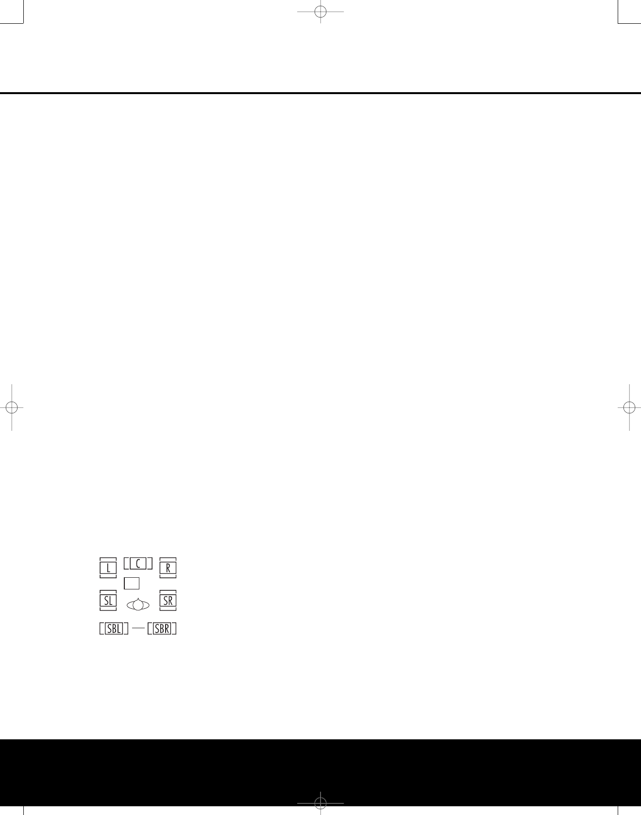
OPERATION
38 OPERATION
for “A/V Receiver,” “Compatible Device,” “Audio
Receiver” and “Human Interface Device.” When all
messages have appeared and then cleared the
screen, you are almost ready to begin.
Before selecting the USB input, first make certain
that one of the media players listed above has been
opened on the computer. Then you may select the
USB input in any of the following ways:
• To select USB as a source from the front panel,
press the Input Source Selector Button 7until
USB appears as the input name in the Upper Display
Line #and in the semi-OSD display, if available.
The USB Input Source Indicator !will also
light up on the front panel.
• To select USB as the input using the main remote
press the Input Selector 4with DMP printed on
the button twice.
• To select USB as the input using the ZR 10 remote,
press the USB Input Selector
∂
.
When the USB input is selected and the AVR 445 is
connected to a compatible computer with one of the
media players mentioned above open, you may then
use either remote’s transport controls to start and stop
playback, as well as move to the next track. Activity of
the Transport buttons may vary from one media player
to another, but at the very least you will be able to use
the Play and Stop buttons.
Once playback is started, the audio from a USB source
is treated the same as any other two-channel audio
source, and you may apply any of the appropriate
surround processing modes. When playing back audio
from a computer via the USB connection, the internal
speakers in a laptop computer are often muted.
Speaker/Channel Indicators
In addition to the bitstream indicators, the AVR 445
features a set of unique channel-input indicators that
tell you how many channels of digital information are
being received and/or whether the digital signal is
interrupted (Figure 22).
Figure 22
The letters inside the boxes tell you which channels
are receiving an input signal. Since conventional ana-
log audio is only two channels,the “L” and “R” letters
will light with any analog source. When a digital source
is in use, you will see letters displayed that correspond
to the number of channels in the incoming data
stream, which may be just the L and R for two-chan-
nel PCM or 2.0 Dolby Digital material. When a 5.1
signal is being received, the L/C/R/SL/SR indicators
will light, with the LFE indication also being shown
when an LFE signal is present. All seven indicators,
including the SBL/SBR letters, will light for a 7.1 sig-
nal, and a horizontal line is shown to connect the
SBL/SBR indicators when a 6.1 source is in use.
It is important to note that although Dolby Digital, for
example, is referred to as a “5.1” system, not all Dolby
Digital DVDs or programs are encoded for 5.1. Thus,
it is sometimes normal for a DVD with a Dolby Digital
soundtrack to trigger only the “L” and “R” indicators.
NOTE: Many DVD discs are recorded with both “5.1”
and “2.0” versions of the same soundtrack. When
playing a DVD, always be certain to check the type of
material on the disc. Most discs show this information
in the form of a listing or icon on the back of the disc
jacket. When a disc does offer multiple soundtrack
choices, you may have to make some adjustments to
your DVD player (usually with the “Audio Select” button
or in a menu screen on the disc) to send a full 5.1
feed to the AVR 445. It is also possible for the type of
signal feed to change during the course of a DVD’s
playback. In some cases, the previews of special
material will only be recorded in 2.0 audio, while the
main feature is available in 5.1 audio. The AVR 445
will automatically sense changes to the bitstream and
channel count and reflect them in these indicators.
The letters used by the Speaker/Channel Input
Indicators @will flash to indicate when a bitstream
has been interrupted. This will happen when a digital
input source is selected before the playback starts,or
when a digital source such as a DVD is paused. The
flashing indicators remind you that the playback has
stopped due to the absence of a digital signal and not
through any fault of the AVR 445. This is normal, and
the digital playback will resume once the playback is
started again.
The boxes around the channel indication letters are
used to show which speakers are configured in your
system. A small box around the letter indicates that a
“Small” speaker has been assigned to that position,
while a larger, double box indicates a “Large” speaker
assignment.
Note that in some cases, such as an analog stereo or
2.0 digital sources you will see empty speaker posi-
tion boxes, which indicates that the speaker is active
and will receive sound, but that there is no discrete
signal for that channel. In other cases you may see
letters with no speaker boxes. This indicates that there
is a discrete signal for that channel, but due to the
mode in use (e.g., Dolby VS with a 5.1 source) there
is no signal being sent to the channel.
Night Mode
Aspecial feature of Dolby Digital is the Night mode,
which enables specially encoded Dolby Digital input
sources to be played back with full digital intelligibility
while reducing the minimum peak level by 1/4 to 1/3.
This prevents abruptly loud transitions from disturbing
others, without reducing the impact of the digital
source. The Night mode is available only when Dolby
Digital signals with special data are being played.
The Night mode may be engaged at any time when
aDolby Digital source is playing by pressing the Night
Mode Button T
.
Each press of the button will
change the Night mode setting, as shown in the lower
third of the on-screen display (except when HDMI,
720p or 1080i sources are in use). To turn the
Night mode off, press the button as described, until
D-RANGE OFF is shown.
The Night mode may also be selected to always be on
at either level of compression using the options in the
DOLBY SURROUND menu. See page 25 for
information on using the menus to set this option.
IMPORTANT NOTES ON DIGITAL PLAYBACK:
•When playing DVDs, please note that even when you
have selected a specific digital audio format for play-
back, an individual disc may change formats or the
number of available channels during playback. For
example, even if you select a DTS mode for the movie,
you may see Dolby Digital in use when the trailers,
menus or copyright warnings are playing. This is not a
fault with either the AVR or your DVD player, as both
are responding to the way the disc was created.
•When viewing digital television signals, note that the
number of audio channels available may vary during
the course of a program, depending on the content.
For example, while a sports event may have 5.1
sound, the commercials or local station content may
be in 2.0. In addition, not all local stations are currently
equipped for carrying the 5.1 digital audio signals. This
may mean that even though the actual program is
produced with 5.1, it may be transmitted in a 2.0
configuration in some areas. Your AVR will automatically
change to react to the proper type of audio stream if it
is changed by the broadcast station.
•Although the AVR 445 will decode virtually all current
DVD movies, CDs and HDTV sources, it is possible
that some future digital sources may not be compati-
ble with the AVR 445.
• Not all digitally encoded programs contain full 5.1-
or 6.1-channel audio. Consult the program guide
that accompanies the DVD or laser disc to deter-
mine which type of audio has been recorded on the
disc. The AVR 445 will automatically sense the type
of digital surround encoding used and adjust to
accommodate it.
LFE
AVR445 OM 6/23/06 3:13 PM Page 38

OPERATION
OPERATION 39OPERATION 39
•When a digital source is playing, you may not be
able to select some of the analog surround modes
such as Dolby Pro Logic II, Dolby Pro Logic IIx,
Stereo, Hall, Theater or Logic 7.
•When a Dolby Digital or DTS source is playing,
tomake an analog recording using the Tape
Outputs 2and Video 1 Audio Outputs g,
you must change the REC OUT setting on
the second page of the IN/OUT SETUP
menu (Fig. 3) to DSP DWNMIX.The digital
signals will be passed through to the Digital Audio
Outputs XY.
Using
The AVR 445 is equipped for use with Harman Kardon’s
optional iPod docking station.
When The Bridge is connected to the AVR and an
iPod properly docked, you may use either remote to
control the iPod for audio playback while using the
front-panel display and on-screen semi-OSD mes-
sages to help you locate tracks or view information
about the track being played. In addition, connecting
an iPod to the AVR 445 through The Bridge also
charges the iPod’sbattery. You may even have the
AVR 445 automatically turn on with your iPod as a
playback source whenever the iPod is turned on, by
using the DMP AUTO POWER menu option,
described on page 43.
To select The Bridge as the AVR’s input source:
• From the front panel, press the Input Source
Selector 6on the front panel as needed.
• From the main remote, press the DMP Input
Selector 3.
•From the ZR 10 remote, press the /DMP S
®
.
When The Bridge is connected and a compatible iPod
properly docked, the iPod’smenu will be replaced with
“harman/kardon” at the top of the iPod’s screen and
the front-panel display and semi-OSD message will
show messages that will guide you through the menu
and content selection. If the Lower Display Line D
shows an UNPLUGGED…message, please
check to see that the correct iPod adapter is used in
The Bridge and that the iPod is properly seated.
The AVR’sfront-panel controls may also be used to
access a limited number of iPod functions. Press the
Tuning Mode Button 7to play or pause the cur-
rent track. The Tuning Selector 3may be used to
search in reverse (left side of button) or forward (right
side of button) through the tracks.Press the Tuner
Band Selector 4to call up the iPod’smenu. Press
the Preset Station Selectors 5to scroll and the
Set Button Ito select. For complete information
on using the remote or front-panel controls to operate
an iPod, see the instructions that are included with
The Bridge.
AM/FM Tuner Operation
The AVR 445’s AM/FM tuner is capable of tuning AM,
FMand FM Stereo broadcast stations. Stations may be
tuned manually, or they may be stored as favorite sta-
tion presets and recalled from a 30-position memory.
Tuner and Station Selection
The AVR 445’s AM/FM tuner may be selected as the
unit’s source, and stations changed, by following one
of these steps:
• From the front panel, press the Input Source
Selector 6until the desired tuner frequency band
(AM, FM or XM) appears. To change stations within
afrequency band, press the Tuning Selection 3.
•You may also press the front panel’s Tuner Band
Selector 4to select the tuner. The first press
will select the last used frequency band and station.
Subsequent presses will change the frequency
bands, selecting the last used station or XM pro-
gram used. Press the Tuning Selection 3to
change stations within a frequency band.
• From the main remote, press the Tuner/FM Select
Button Xby pressing the button up towards
the top of the remote. The first press of the button
selects the frequency band and station or XM
channel that was last tuned. Press the button
again to select between FM, AM and XM. You may
also directly select the FM tuner by pressing the
Tuner/FM Select Button Xdown toward the
bottom of the remote. To change stations, press
the Tuning Up/Down Button M.
•To select the tuner from the ZR 10 remote, press
the Tuner Selector
É
, or for XM Radio press
the XM Radio Selector Button
ƒ
(when an
optional XM Connect & Play module is connected
and the programming service has been activated).
•To change the tuning mode, press the Tuning Mode
Button 7B
ø
.
When the button is pressed so that AUTO/
STEREO appears in the Upper Display Line #,
each press will put the tuner in a scan mode that
seeks the next higher or lower frequency station with
acceptable signal strength. An AUTO ST
TUNED indication will momentarily appear when
the station stops at a stereo FM station, and an
AUTO TUNED indication will momentarily appear
when an AM or monaural FM station is tuned. Press
the Tuning buttons again to scan to
the next receivable station.
When the button is pressed so that MANUAL/
MONO appears in the Upper Display Line #,
each tap of the Selector will increase or decrease
the frequency by one increment. When the tuner
receives a strong-enough signal for adequate recep-
tion, MANUAL TUNED will appear in the
Lower Display Line $.
•Stations may also be tuned directly in either the
automatic or manual mode. To enter a station’s
frequency directly, first select the AM or FM band
as shown above. Next, press the Direct Button
8
µ
.Within 5 seconds of when
DIRECT IN scrolls in the Upper Display
Line #, enter the station frequency by pressing
the Numeric Keys k
∆
. If you press an
incorrect button while entering a direct frequency,
press the Clear Button 9
¬
to start over.
NOTE: When FM reception of a station is weak, audio
quality will be increased by switching to Mono mode
by switching to the MANUAL/MONO mode.
Preset Tuning
Using the remote, up to 30 AM or FM stations may be
stored in the AVR 445’s memory for easy recall, using
the front-panel controls or the remote.
Toenter a station into the memory, first tune the station
using the steps outlined above.Then:
1. Press the MemoryButton b
ñ
;the station’s
frequency will flash.
2. Within 5 seconds, press the Numeric Keys
c
∆
corresponding to the location where you
wish to store this station’s frequency. Once entered,
the preset number will appear in the Upper Display
Line #.
3. Repeat the process after tuning any additional
stations to be preset.
Recalling Preset Stations
•To manually select a station previously entered
in the preset memory,press the Numeric Keys
c
∆
that correspond to the desired station’s
memory location.
•Tomanually tune through the list of stored preset stations
one by one, press the Preset Buttons 6v on
the front panel or the main remote, or the Prev/Next
Transport Controls
π
on the ZR 10 remote.
XM Radio Operation
XM Radio is a satellite-delivered service that offers
hundreds of program channels, as well as local traffic
and weather information for select cities.The AVR 445
is “XM Ready,” which means that the unit is able to
receive the XM service when an optional XM Connect
&Play module is connected and the service activated.
You may purchase the antenna module needed for
XM Radio from many electronics or online retailers, or
directly from XM Radio through the “Home Receivers”
section of the XM Radio Store at www.xmradio.com.
The
Bridge
TM
The
Bridge
TM
The
Bridge
TM
AVR445 OM 6/23/06 3:14 PM Page 39

OPERATION
40 OPERATION
Once you have purchased the XM module, follow
the instructions accompanying it to activate the XM
Service. Connect the plug on the XM module to the
XMReady Input Vonthe rear panel of the AVR
445. For best results, point the antenna module out a
window, again, following the instructions packed with
the XM product. If a window view is not available for
the antenna, XM Radio operates a series of terrestrial
repeater stations that may be able to provide recep-
tion, though this service is not available everywhere.
IMPORTANT NOTE: XM Radio requires both the
optional, external antenna module and a sub-
scription to the XM Radio service. Antenna and
service sold separately; XM Radio is not avail-
able in Alaska or Hawaii.
If you need to view the antenna module’snumber,
connect it to the AVR and then follow one of the steps
shown below to select XM Radio as the input source.
Tune to “000” to get a readout of the number.
Once you have an activated module connected, follow
one of these steps to select XM Radio as your sys-
tem’saudio source:
• From the front panel, press the Input Source
Selector 6. If XM was the last-used tuner source,
it will appear; or press the button again until XM
Radio is heard. Press the Tuning Selector 3to
change stations within a frequency band. Press the
Tuning Selector 3to select a different XM channel.
• From the main remote, press the Tuner/FM Select
Button Xby pressing the button up towards the
top of the remote as needed until XM Radio is
shown as the source. To change stations, press the
Tuning Up/Down Button M.
•Toselect the tuner from the ZR 10 remote control,
press the XM Radio Selector Button
ƒ
.
Channels are selected using the Prev/Next
Transport Controls
π
.
While using XM Radio is similar in many ways to
AM/FM terrestrial radio, the wide range of program
choices available, as well as the ability of the XM serv-
ice to add special data and information tags into the
digital audio data stream, means that some of the
front-panel and remote controls traditionally used
for tuner operation have different functions with
XM Radio.
• When XM Radio is the AVR’s source, the channel
number will appear in the Upper Display Line C,
along with an indication of the Preset number, if any,
and a series of bars at the far right end of the dis-
play. These bars (not shown in the semi-OSD mes-
sage), show the current signal strength similar to the
signal strength displays on a cellular phone.
• The current channel’s name will normally appear in
the Lower Display Line D. For local traffic infor-
mation, the name of a city will be shown in place of
the channel name. You may change this display to
show the current artist and track title information by
pressing the Tuning Mode Selector 7B
ø
.
When you are listening to a channel with local traffic
information in the “200” series of channel numbers,
these buttons change the display to show the tem-
perature and current weather for the selected city.
•To tune a channel number directly, simply press the
Numeric Keys c
∆
. Unlike standard AM/FM
tuner operation, it is not necessary to press the
Direct button first.
•The AVR 445 has five banks of preset memories
for XMRadio, each with eight memory positions
and designated by a letter (“A” through “E”). To
store a channel into a memory group, first press
the Set Button F
œ
until PRESET
SEARCH appears in the Upper Display Line
Cand on the top line of the semi-OSD display.
Next, press the ‹/›Navigation Buttons D
©
until the desired preset memory bank letter
appears in the Lower Display Line Dand in the
bottom line of the semi-OSD display. Next, press the
MemoryButton b
ñ
and note that a dash
will start to flash next to the preset memory bank
letter. Within five seconds, press the Numeric
Button c
∆
from 1 to 8 for the memory slot
you wish to use.
• Totune up or down through a list of channels stored
in the currently active preset memory, press the
Preset Up/Down Buttons L. You may also
use the Preset Station Selector 5on the front
panel, or the Prev/Next Transport Controls
π
on the ZR 10 remote. To change to another preset
bank, press the Set Button FI
œ
and then
press the ‹/›Navigation Buttons HD
©
until the desired preset memory bank letter appears
in the Lower Display Line Dand in the bottom
line of the semi-OSD display.
•Each XM Radio channel is assigned a category,
which may be viewed by pressing the Tuning
Mode Selector B7
ø
. You may search for
an XM channel in any of the categories by first
pressing the Set ButtonFI
œ
and then
pressing the ‹/›Navigation Buttons HD
©
until the desired categoryname appears in the
Lower Display Line Dand in the bottom line
of the semi-OSD display. Press the Set Button
FI
œ
again to start the search for the next
channel in that category.
• Note that you may see a LOADING message,
indicating that the XM tuner is downloading content
and may not be able to operate.If the message
continues to appear, check to see whether the XM
antenna is properly positioned toward a south-facing
window, experiment with the antenna position, or
change to another input and then reselect XM Radio.
Recording
In normal operation, the audio or video source
selected for listening through the AVR 445 is sent to
the record outputs. This means that any program you
are watching or listening to may be recorded simply
by placing machines connected to the outputs for
Tape Outputs £orVideo 1 Audio and Video
Outputs Sgin the record mode. Remember that
if your source is Dolby Digital or DTS, and you wish
to make an analog recording, you must change
the REC OUT setting on the second page of
the IN/OUT SETUP menu (Figure 3) to
DSP DWNMIX.
When a digital audio recorder is connected to the
Digital Audio Outputs XY, you are able to record
the digital signal using a CD-R, MiniDisc or other digi-
tal recording system.
NOTES:
•The digital outputs are active only when a digital sig-
nal is present, and they do not convert an analog
input to a digital signal, or change the format of the
digital signal. In addition, the digital recorder must
be compatible with the output signal. For example,
the PCM digital input from a CD player may be
recorded on a CD-R or MiniDisc, but Dolby Digital
or DTS signals may not.
•The Front-Panel Video 4 Njacks may be config-
ured for use as outputs, allowing connection to a
recorder, when the steps shown in the section below
are followed.
• Please make certain that you are aware of any
copyright restrictions on any material you copy.
Unauthorized duplication of copyrighted materials
is prohibited by federal law.
Front-Panel Connections
In addition to the rear-panel digital and analog outputs,
the AVR 445 offers Harman Kardon’s exclusive config-
urable front-panel output-jack feature. For easy con-
nection of portable devices, you may switch the front-
panel Video 4 Jacks Nfrom an input to an output
by changing the VIDEO 4 setting on the second
page of the IN/OUT SETUP menu (Figure 3)
from IN to OUT.
Once the setting is made, the Input/Output Status
Indicator Mwill turn red, indicating that the jacks are
now outputs, instead of the default setting as inputs.
Once changed to an output, the setting will remain as
long as the AVR 445 is turned on, unless the setting
is changed in the OSD menu system. However, once
the AVR 445 is turned off, the setting is canceled.
When the unit is turned on again, the front-panel jacks
will return to their normal default setting as inputs.
AVR445 OM 6/23/06 3:14 PM Page 40

OPERATION 41
OPERATIONOPERATION
Output Level Trim Adjustment
Normal output level adjustment for the AVR 445 is
established using EzSet/EQ, as outlined on pages
26–28. In some cases, however, it may be desirable
to trim the output levels using program material such
asatest disc, or a selection you are familiar with.
Additionally, the output level for the subwoofer can
only be adjusted using this procedure.
To adjust the output levels using program material, first
set the reference volume for the front left and front right
channels using the Volume Control )H
˙
.
Once the reference level has been set, press the
Channel Select Button CEand FRONT L
LEVEL will appear in the Lower Display Line $.
To change the level, first press the Set Button
IF, and then use the ⁄/¤Navigation Buttons
HDto raise or lower the level. DO NOT use the
volume control, as this will alter the reference setting.
Once the change has been made, press the Set
Button IF;then press the ⁄/¤Navigation
Buttons HDto select the next output-channel
location that you wish to adjust. Toadjust the sub-
woofer level, press the ⁄/¤Navigation Button
Ho until WOOFER LEVEL appears in the
Lower Display Line $or on-screen display.
Repeat the procedure as needed until all channels
requiring adjustment have been set. When all adjust-
ments have been made and no further adjustments
are made for 5 seconds, the AVR 445 will return to
normal operation.
The output levels may also be adjusted using the
on-screen menu system to either the internal test tone
or an external test disc by following the instructions
shown on page 31.
EzSet/EQ On/Off
Ifyou wish to turn the filter settings established
by EzSet/EQ on or off to demonstrate the impact
EzSet/EQ has on the sound of your system, simply
press the EzSet/EQ On/Off button A. Using this
feature does not change the settings; it merely puts
them in or out of the signal path.
Dim Function
Since the AVR 445 will often be used when movies
orother kinds of video programming are viewed under
low-light conditions, you may wish to lower the bright-
ness of the front-panel displays and indicators so that
they do not distract from the video presentation. You
may dim the displays using the menu system, as
shown on page 42, or you may control the brightness
directly from the remote.
Simply press the Dim ButtonWonce to dim the
front panel to half the normal brightness level; press it
again to turn the displays off. Note that when the
displays are dimmed or turned off, the blue lighting
around the Standby/On Switch 1will continue to
stay lit as a reminder that the AVR is still turned on.
The accent lighting for the Volume Control )will
remain at its normal level, rather than dim when the
panel displays are at half-brightness.
Note that all changes to the front-panel brightness
level are temporary; the displays will return to full-
brightness after the AVR is turned off and then on
again. Toreturnthe displays to full-brightness without
turning the unit off, press Dim Button Was needed
until the displays are on.
In addition to lowering the brightness of the displays
or turning them off completely, you may wish to have
them appear whenever a button on the remote or
front panel is pushed, and then gradually fade out after
aset time period. You may do this by making the
appropriate settings in the VFD FADE TIME
OUT line of the ADVANCED SELECT
menu, as shown on page 42.
Memory Backup
This product is equipped with a memorybackup
system that preserves the system configuration infor-
mation and tuner presets if the unit is accidentally
unplugged or subjected to a power outage.This
memory will last for at least four weeks, after which
time all information must be reentered.
AVR445 OM 6/23/06 3:14 PM Page 41

ADVANCED FEATURES
42 ADVANCED FEATURES
The AVR 445 is equipped with a number of advanced
features that add extra flexibility to the unit’s operation.
While it is not necessary to use these features to
operate the unit, they provide additional options that
you may wish to use.
To change a setting from its factory default, you will
use the ADVANCED menu. Press the OSD
Button U
∫
to call up the MAIN MENU
(Figure 1). Next, press the ⁄/¤Navigation
Buttons D
©
so that the cursor is next to
ADVANCED; then press the Set Button
p
œ
.When the ADVANCED menu (Figure
23) appears,follow the instructions shown below to
make any needed configuration adjustments.
Figure 23
Front-Panel Display Fade
In normal operation, the front-panel displays and indi-
cators remain on at full-brightness, although you may
also dim them or turn them off, as shown on page 41.
As an additional option, you may also set the AVR so
that the displays are on whenever a button is pressed
on the front panel or remote, but then fade out after a
set period of time.
With the ADVANCED menu on your video dis-
play, press the ⁄/¤Navigation Buttons D
©
so that the cursor is pointed to the VFD FADE
TIME OUT line. Next, press the ‹/›Navigation
Buttons D
©
so that the amount of time that you
wish the displays to fade out after a button is pressed
is shown. When OFF is selected, there is no display
fade-out.
Once this time is set and the unit returned to normal
operation, the displays will remain on for the time
period selected whenever a button is pressed on the
front panel or remote. After that time, they will gradually
fade out, with the exception of the lighting surrounding
the Standby/On Switch 1,which remains on to
remind you that the AVR is turned on. Note that if the
displays have been turned completely off using the
Dim function, the Fade function will not operate.
If you wish to make adjustments to other items
on the ADVANCED menu,press the ⁄/¤
Navigation Buttons D
©
so that the cursor is
next to the desired item, or place the cursor next to
the BACK TO MASTER MENU line and
press the Set Button F
œ
tomake an adjust-
ment to another menu. If you have completed
all adjustments, press the OSD Button U
∫
to exit the menu system.
Display Brightness
The AVR 445’s front-panel displays and indicators are
set at a default brightness level that is sufficient for
viewing in a normally lit room. However, you may wish
to occasionally lower the brightness of the display, or
turn it off completely.
Next, press the ⁄/¤Navigation Buttons D
©
until the cursor is next to the VFD line. Press the ‹/›
Navigation Buttons D
©
until the desired bright-
ness level is highlighted in the video display. When
FULL is highlighted, the display is at its normal bright-
ness. When HALF is highlighted, the display is at
half the normal brightness level. When OFF is high-
lighted, all of the front-panel indicators will go dark.
However, the blue lighting surrounding the Standby/
On Switch 1will remain lit to remind you that the
AVR is still turned on.
Once the desired brightness level is selected, it will
remain in effect until it is changed again or until the
unit is turned off.
If you wish to make other adjustments, press the
⁄/¤Navigation Buttons D
©
until the cursor
is next to the desired setting or the BACK TO
MASTER MENU line and press the Set Button
F
œ
. If you have no other adjustments to make,
press the OSD Button U
∫
to exit the menu
system.
Turn-On Volume Level
As is the case with most audio/video receivers,when
the AVR 445 is turned on, it will always returnto the
volume setting in effect when the unit was turned off.
However, you may prefer to always have the AVR 445
turnon at a specific setting, regardless of what was
last in use when the unit was turned off.
With the ADVANCED menu on the screen, press
the ⁄/¤Navigation Buttons D
©
as needed
until the cursor is next to the DEFAULT VOL
SET line. Press the ‹/›Navigation Buttons
D
©
until the desired volume level is shown on
the DEFAULT VOL SET line. This setting
may NOT be made with the regular volume controls.
NOTE: Since the setting for the turn-on volume can-
not be heard while the setting is being made,you
may wish to determine the setting before making the
adjustment. To do this, listen to any source and adjust
the volume to the desired level using the regular
Volume Controls )H
˙
. When the desired
volume level to be used at turn-on is reached, make
anote of the setting as it appears in the lower third of
the video screen or in the Lower Display Line $.
(A typical volume level will appear as a negative
number such as –25dB.) When making the adjust-
ment, use the ‹/›Navigation Buttons D
©
toenter this setting.
Unlike some of the other adjustments in this menu,
the turn-on volume default will remain in effect until
itis changed or turned off in this menu, even when
the unit is turned off.
Ifyou wish to make other adjustments, press the
⁄/¤Navigation Buttons D
©
until the on-
screen cursor is next to the desired setting or the
BACK TO MASTER MENU line, and press
the Set Button F
œ
. If you have no other adjust-
ments to make, press the OSD Button U
∫
to
exit the menu system.
Semi-OSD Settings
The semi-OSD system places one-line messages at
the lower third of the video display screen whenever
the Volume, Input Source, Surround Mode, Tuner
Frequency or any of the configuration settings is
changed (except when HDMI, 720p or 1080i sources
are in use). The semi-OSD system is helpful in that it
enables you to have feedback on any control changes
or remote commands using the video display when
it is difficult to view the front-panel displays. However,
you may also prefer to turnthese displays off perma-
nently. You may also want to adjust the length of time
the displays remain on the screen. Both of those
options are possible with the AVR 445.
With the ADVANCED menu on the screen, press
the ⁄/¤Navigation Buttons D
©
so that the
cursor is pointing to the SEMI OSD/TIME
OUT line.Then select one of these options:
• To keep the semi-OSD system activated, but to
adjust the length of time the displays remain on
the screen, press the ‹/›Navigation Buttons
D
©
until the desired time-out is shown. The
default setting is 5 seconds.
• To turn the semi-OSD system off so that it does not
appear at any time, press the ‹/›Navigation
Buttons D
©
so that OFF is shown on the
right side of the line.
To make other adjustments, press the ⁄/¤
Navigation Buttons D
©
until the cursor is
next to the desired setting or the BACK TO
MASTER MENU line and press the Set Button
F
œ
.If you have no other adjustments to make,
press the OSD Button U
∫
to exit the menu
system.
* ADVANCED *
VFD FADE TIME OUT: OFF
VFD BRIGHTNESS: FULL
VOLUME DEFAULT: OFF ON
DEFAULT VOL SET: -25dB
SEMI OSD TIME OUT: 5S
FULL OSD TIME OUT: 20S
DMP AUTO POWER: OFF ON
BACK TO MASTER MENU
→→
AVR445 OM 6/23/06 3:14 PM Page 42

ADVANCED FEATURES
ADVANCED FEATURES 43
Full-OSD Time-Out Adjustment
The FULL OSD menu system is used to simplify
the setup and adjustment of the AVR 445 by using a
series of on-screen menus. The factory default setting
for these menus leaves them on the screen for 20
seconds after a period of inactivity before they disap-
pear from the screen (Time-Out). Time-Out is a safety
measure to prevent image retention of the menu text
inyour monitor or projector, which might happen if it
were left on indefinitely. However, some viewers may
prefer a slightly longer or shorter period before the
on-screen display disappears.
With the ADVANCED menu on the screen
(Figure 23) make certain that the cursor is next to the
FULL OSD TIME OUT line by pressing the
⁄/¤Navigation Buttons D
©
as needed.
Next, press the ‹/›Navigation Buttons D
©
until the desired time is displayed in seconds. Unlike
most of the other options in this menu, this is a per-
manent setting change, and the Time-Out entry will
remain in effect until it is changed, even if the unit is
turned off.
If you wish to make other adjustments, press the
⁄/¤Navigation Buttons D
©
until the cursor
is next to the desired setting or the BACK TO
MASTER MENU line and press the Set Button
œ
. If you have no other adjustments to make, press
the OSD Button U
∫
to exit the menu system.
DMP/ Auto Power
When using Harman Kardon’soptional
iPod docking station, the normal operation is to have
the iPod selected as the input source only when it is
specifically chosen. However, you may set the AVR so
that whenever the iPod is turned on, the AVR will also
turn on automatically and set The Bridge as the input.
To change the setting, first make certain that the
ADVANCED menu (Figure 23) is on the screen,
and then press the ⁄/¤Navigation Buttons
D
©
until the cursor is pointing to DMP
AUTO POWER. Press the ⁄/¤Navigation
Buttons D
©
so that ON is highlighted to have
the AVR turn on in sync with an iPod, or OFF for
standard operation.
The
Bridge
TM
The
Bridge
TM
AVR445 OM 6/23/06 3:14 PM Page 43

44 MULTIROOM OPERATION
The AVR 445 is fully equipped to operate as the con-
trol center for a complete multiroom system that is
capable of sending one audio source to a second
zone in the house while a separate source is listened
toin the main room. In addition to providing for con-
trol over the selection of the remote source and its
volume, the AVR 445 offers a comprehensive range of
options for powering the speakers in the second zone.
• Using the line-level Multiroom Audio Outputs 8,
the selected source may be fed to optional, external
power amplifiers that may be matched to the
specifics of the installation.
• When the main room system is configured for 5.1
operation, the Surround Back Left/Right amplifier
channels may be used to power the remote zone so
that no additional amplifiers are required.
• Using built-in A-BUS/READY technology, optional
A-BUS modules may be connected to the AVR 445
via a single Category 5/5e or higher cable, so that
remote zone speakers may be powered directly
from the A-BUS module without the need for addi-
tional power, IR sensor or volume control wires to
be run to the second zone.
In addition, the AVR 445 includes a remote IR sensor
input so that remote control commands from the
ZR 10 remote included with the unit may be transmitted
to the unit, while standard IR input/output jacks allow
the remote zone’scommands to be sent to compatible
IR-controlled source devices.
Installation
Although simple remote room systems may be
installed by the average do-it-yourself hobbyist,
the complexity of your multizone/multiroom system
involves running wires inside of walls where the ser-
vices
of a specially trained installer may be required.
Regardless of who does the work, please remember
that local building codes may governin-wall electrical
work, including proper specification of any wiring used
and the way in which it is connected. You are respon-
sible for making certain that all multiroom installation
work is done properly and in compliance with all appli-
cable codes and regulations.
For standard installations, follow the instructions shown
on pages 18–19 for the connection of speaker wire
and IR remote wiring to the AVR 445.
For installations where the Surround Back Left/Right
amplifier channels are used to power the remote zone,
make certain that the system is configured for that
type of operation, as shown on this page.
For installations where A-BUS modules are used, fol-
low the instructions provided with the A-BUS remote
modules or keypads. Additional information will also be
made available through the Harman Kardon Web site
atwww.harmankardon.com.
RS-232 Control
The AVR 445 provides the capability for full bidirec-
tional remote control from compatible computers or
specialized remote control systems. RS-232 program-
ming requires specialized programming knowledge
and for that reason we recommend that it only be
done by qualified professionals. For more information
on using the RS-232 port for remote control, visit the
Harman Kardon Web site at www.harmankardon.com
or contact our customer service department.
Multiroom Setup
Once the audio and IR link connections have been made,
the AVR 445 needs to be configured for multiroom
operation. To change a setting from its factory default,
use the MULTI-ROOM menu. First, press
the OSD Button U
∫
to call up the MAIN
MENU (Figure 1). Next, press the ⁄/¤Navigation
Buttons D
©
so that the cursor is next to
MULTI-ROOM,then press the Set Button
F
œ
.When the MULTI-ROOM menu
(Figure 24) appears, follow the instructions shown below
to make any needed configuration adjustments.
Figure 24
When the MULTI-ROOM menu appears, the
cursor will be at the MULTI-ROOM line.Since
this line is used to turn the system on and off, don’t
make an adjustment here unless you wish to turn the
system on at this time. To turn the system on, press the
›Navigation Button D
©
so that ON is high-
lighted. If you do not wish to turn the system on at this
time,or to proceed to the next step,press the ⁄/¤
Navigation Buttons D
©
so that the on-screen
cursor is next to the MULTI IN line.
Atthe MULTI IN line, press the ‹/›Navigation
Buttons D
©
until the desired input to the multi-
room system appears in the highlighted video. In addi-
tion to direct selection of any active input source, you
may also select the DSP DWNMIX mode, which
outputs a two-channel down-mixed version of multi-
channel digital sources. When the selection has been
made, press the ¤Navigation Button D
©
once so that the cursor is next to MR VOL.
At the MR VOL line, press the ‹/›Navigation
Buttons D
©
until the desired volume level for
the multiroom system is entered. DO NOT use the
regular volume control knobs for this setting. When
all settings for the multiroom setup have been made,
press the ⁄/¤Navigation Buttons D
©
until
the cursor is next to the BACK TO MASTER
MENU line. If you have no other adjustments to
make, press the OSD Button U
∫
to exit the
menu system.
Surround Channel Amplifier Assignment
The AVR 445 is equipped with seven full-power
amplifier channels to allow for complete 7.1-channel
operation. However, if your system is only configured
for 5.1 channels in the main listening room, you may
take advantage of the “extra” two channels by using
them to power speakers placed in a second-zone
location. This enables you to use the multiroom capabili-
ties of the AVR 445 without the cost of an additional,
external power amplifier.
Tochange the setting so that the Surround Back
amplifiers are fed by the source selected through
the Multiroom system rather than the SBL/SBR
channels of the main room, make certain that the
MULTI-ROOM menu (Figure 24) is on the
screen; then press the ⁄/¤Navigation Buttons
D
©
so that the cursor is pointing to the SB
AMPS line. Press the ‹/›Navigation Buttons
D
©
so that MULTI is shown in highlighted
video. When this change is made, connect the wires
feeding the remote zone speakers to the Surround
Back/Multiroom Speaker Outputs E.
When the SBL/SBR speakers are set for multiroom
operation, you may still configure the AVR 445 for 7.1
modes in the main listening room by making certain
that the SURR BACK line in the SPEAKER
SIZE menu (Figure 18) is set to SMALL or
LARGE, as shown in the instructions on pages
29–30. When that is done, the word MULTI will
appear next to the large or small designator to alert
you to the fact that the internal SBL/SBR amplifiers
are assigned to the multiroom system, and that an
optional, external two-channel power amplifier must be
connected to the SBL/SBR Preamp Outputs ¡in
order to use surround back channel speakers.
*MULTI-ROOM *
MULTI-ROOM:OFF ON
MULTI IN:FM PRESET 01
MR VOL:Ð25dB
SB AMPS:MAIN MULTI
CARRIER OUT: ZONE II
BACK TO MASTER MENU
→→
MULTIROOM OPERATION
AVR445 OM 6/23/06 3:14 PM Page 44

MULTIROOM OPERATION
MULTIROOM OPERATION 45
Once this setting is made, press the ⁄/¤
Navigation Buttons D
©
to select another
configuration item on this page, or press the OSD
Button U
∫
if you have completed your
adjustments to the Multiroom system.
Infrared Output Selection
The AVR 445 enables you to select which IR input
will be used to feed the Full Carrier IR Output B.
The factory default setting is the IR signal that is fed
tothe Multiroom IR Input N,but you may select
other options.
To change this setting, first make sure that the
MULTI-ROOM menu is on the screen, and
then press the ⁄/¤Navigation Buttons D
©
so that the cursor is next to CARRIER OUT;
then press the Set Button F
œ
. Press the
⁄/¤Navigation Buttons D
©
to select
one of these options:
•ZONE II feeds the signal present at the
Multiroom IR Input Nto the Full Carrier IR
Output B.
•A-BUS feeds the signal carried back from an
optional A-BUS module connected to the AVR to
the Full Carrier IR Output B.
•FRONT feeds the received through the front-
panel Remote Sensor Window ^to the Full
Carrier IR Output B.
When all the necessaryadjustments to the
MULTI-ROOM menu have been made, press
the ⁄/¤Navigation ButtonsD
©
until the
cursor is pointing to BACK TO MASTER
MENU to make changes to other menus, or press
the OSD Button U
∫
to exit the menu system
and return to normal operation.
Multiroom Operation
When operating the AVR 445 from a remote room
where an IR sensor or A-BUS module has been
installed and properly connected back to the AVR,
you may use either the main remote control, the
ZR 10 or any remote programmed with standard
Harman Kardon remote control codes. Unlike many
other products, the AVR 445 does not use different
codes for main room and remote room operation.
To turn the AVR on from the remote room, simply
point the remote at the sensor and press either the
AVR Selector 4
ç
, any of the Input Selectors
∂
3,or the discrete source selection buttons for
inputs such as the Tuner
É
X,XM Radio
ƒ
or
®
. To turn the multiroom system
off from a remote room, press the Power Off Button
å
1.
When the multiroom system is turned on, you may
use the same buttons on either remote that would
normally be used to control an AVR function such as
volume, source selection, tuner control or the opera-
tion of an iPod docked to The Bridge. If any of the
input devices are connected to the IR Output Cor
Full Carrier IR Output B, by either a hard-wire con-
nection or through an optional IR “blaster,” you may
use the Transport Controls
π
on the ZR 10 to
operate compatible Harman Kardon products.
To turn the system off from the remote room, press
the Power Off Button 0
å
. Remember that the
AVR 445 may be turned on or off from the remote
room, regardless of the system’s operation or status
in the main room.
NOTE: When XM Radio or the tuner is selected as
the source for the remote zone, any change to the
frequency or preset will also change the station being
listened to in the main room, if the tuner is in use
there. Similarly, if someone in the main room changes
the station, the change will also have an impact on
the remote room.
To turn the multiroom system on or off from the
room where the AVR is located, press the Multiroom
Button Q.When the MULTI ON/OFF
message appears in the Lower Display Line $
press the Set Button Fand then press the ‹/›
Navigation Buttons Dso that the display changes
to MULTI ON or MULTI OFF,as desired.
Press the Set Button Fagain to activate the
command.
NOTE: The multiroom system will remain on even
when the AVR is turned off in the main listening room
where it is located. When the AVR 445’s multiroom
system is turned on, but the unit is in the Standby
mode (turned “off”) in the room where the AVR 445
is located, the light surrounding the front-panel
Standby/On Switch 0will remain blue, rather than
amber, and a MULTI-ROOM ON message
will be shown in the Lower Display Line D.
When the Multiroom system is turned on, the input
selected using the Multiroom menu will be fed to the
Multiroom Audio Outputs 8on the rear panel as
well as the A-BUS Connector ¢. The volume will be
as set in the previous selection, although it may also be
adjusted using an optional IR sensor and the ZR 10
remote in the remote location, or the A-BUS keypad,
or on the optional audio power amplifier connected to
the Multiroom Audio Outputs 8.
Although changes to the input source or remote room
volume will normally be made using an IR sensor in
the remote room that is connected to the AVR, it is
also possible to change those settings from the main
listening room. This is useful for situations where some
or all of the remote rooms do not have an IR sensor,
or to take control over the remote room without
actually being in that room.
To change the input source or volume in the remote
zone from the room where the AVR is located, press
the Multiroom Button Q.When the MULTI
ON/OFF message appears in the Lower Display
Line $, press the Set Button Fand then
press the ⁄/¤Navigation Buttons Dso that the
display changes to either MULTI INPUT or
MULTI LEVEL,depending on which setting
you wish to change. Press the Set Button Fagain
and then use the ‹/›Navigation Buttons Dto
change the input or volume. Press the Set Button F
one more time to activate the command.
Note that the this volume adjustment controls the level
for the output to the Multiroom Audio Outputs 8
and for any speakers connected to the Surround
Back/Multiroom Speaker Outputs Ewhen the
Surround Back amplifier channels are configured for
Multiroom use, as shown on page 44. This adjustment
does NOT change the volume level for any room
where an A-BUS module is used, as that setting is
only adjustable using the A-BUS module’svolume
control or a remote pointed at the A-BUS module’s
built-in sensor.
The
Bridge
TM
AVR445 OM 6/23/06 3:14 PM Page 45

46 CONFIGURING THE REMOTE
The AVR 445 remote is factory-programmed for
all functions needed to operate the unit. In addition,
it is also preprogrammed to operate most recent
Harman Kardon DVD players and changers, CD
players and changers, CD recorders and cassette
decks. The codes for other brand devices may be
programmed into the AVR 445 remote using its
extensive library of remote codes or a head-to-head
learning process for codes not in the internal library.
As an alternative to the AVR remote, consider purchasing
Harman Kardon’s TC 30 activity-based remote, which
uses Web setup wizards to custom configure your remote.
Formore information visit www.harmankardon.com.
Thanks to the remote’s advanced technology and
two-line LCD, it is no longer necessary to look up
cumbersome codes when programming the remote;
following the steps outlined below, you simply search
for the brand name from the remote’s memory. We
recommend that you first try the preprogrammed code
entry method. If that procedure is not successful, then
trythe code-learning method.
Preprogrammed Code Entry
The easiest way to program the remote for operation
with a source device from another brand is to follow
these steps:
1. Turn on the power to the device you wish to pro-
gram into the AVR remote. This is important, as in a
later step you will need to see whether the device
turns off to determine whether the remote has been
programmed for the proper remote codes.
2. Press and hold the Program Button yfor
about 3 seconds while the message shown
in Figure 25 appears in the remote’sLCD
Information Display c.Release the button
when the red light under the Set Button F
appears.
Figure 25
3. The remote’s MAIN MENU message
(Figure 26), will appear in the LCD and
the Set Button Fwill remain illuminated
in red. Press the Set Button Fto begin
the process of selecting a device and locating
the proper remote codes.
Figure 26
4. SELECT A DEVICE will appear in the LCD
(Figure 27). Press the
⁄
/
¤
Navigation Button
Dto scroll through the list of device categories
and press the Set Button Fwhen the device
you wish to set the codes for appears. For this
example, we will select “TV” to enter the codes
needed to operate your TV.
Figure 27
NOTE: The codes for hard-drive recorder products
(DVR) such as TiVo®are programmed by selecting VCR
as the device. For satellite-based TiVo products, check
under the brand name of the product.
5. At the next menu screen on the remote (Figure
28), press the Set Button Ftoenter the
Manual mode, which means that you will select
the brand name of the device from the list pro-
grammed into the remote’s memory.
Figure 28
6. The next menu screen on the remote (Figure 29)
will show the start of the list of available brands.
Press the
⁄
/
¤
Navigation Buttons Duntil
the brand name of the device you are program-
ming into the remote appears on the lower line of
the display and then press the Set Button F.
Figure 29
NOTE: If the brand name for the product you wish to
program does not appear in the list, the codes may
still be available, as some manufacturers share codes.
If the desired brand is not listed, press the Clear
Button jto exit the programming process, and
skip to the instructions shown on page 47 for the
“Automatic” method of programming the remote. If
desired, or if the codes for your brand are not part
of the remote’s library at all, you may still use the
remote to program most infrared-controlled products
by “learning” the commands from the product’s
original remote into the AVR remote. The instructions
for Learning Commands are on page 47.
7. The next step is important, as it determines which
codes will operate the source device or display.
Point the AVR remote at the device being pro-
grammed and, following the instructions shown in
the remote’s LCD Information Display c,
press and release the Numeric Keys cshown
on the menu screen (Figure 30) one at a time,
starting with the “1” button. After you press the
“1” Button c,the remote’sLCD screen will
briefly go blank as the code is being transmitted,
but you will see the “transmit” icon in the
upper right corner of the display to serve as
confirmation that the remote is sending out
commands.
Figure 30
8. After you press and release the number key,
watch the device being programmed to see
whether it turns off. As shown in the instructions
that will appear on the next menu screen (Figure
31), if your device has turned off, press the Set
Button F,and then skip to Step 10. If
the unit
does not turn off, proceed to the next step.
Figure 31
9. If the device being programmed into the AVR
remote does not turn off after you have pressed
the “1” Button c, repeat Steps 7 and 8 by
pressing the available numeric keys shown until
the device turns off. If the device still does not turn
off after all choices have been tried, or if there is
only one number key shown as available to try,
the code for this specific device is not in the AVR
remote library under that brand name. If that is the
case, press the Clear Button jto exit the
manual programming mode. Remember that the
codes may still be stored in the AVR remote’s
libraryunder another brand, and you can have the
remote control search for them by following the
instructions below for automatic programming.
You may also manually “learn” the codes for most
devices into the AVR remote by following the
Learning Commands instructions on page 47.
10. When the device being programmed does turn off
after a numeric key has been pressed, you must
press the Set Button Fwithin 5 seconds to
enter the setting into the remote’smemory. After
you press the Set Button F, the top line of the
LCD will read SAVING… and then the word
SAVED will flash four times in the center of
the bottom line.
11. When the codes are saved, the remote will return
to normal operation, and whenever you press
the Input Selector Button dthat was just
programmed, the codes for the new device will
be used. If no further buttons are pressed, the
remote will revert back to the default setting for
AVR commands.
NOTE: Some brands share a common remote control
code for “Power Off” for many models. For that rea-
son, it is possible that even though the remote
appears to be properly programmed, you may find
that some buttons do not appear to issue the correct
command. If this is the case, repeat the procedure
outlined above,
but if more than one numeric key selec-
tion is suggested
in Step 7, try a different number to
POWER OFF? Y:SET
N: NEXT#OR CLR
PRESS A NUMBER
CODE 1 OF 10
SELECT BRAND
RCA
PROGRAM DEVICE
MANUAL
SELECT A DEVICE
TV
MAIN MENU
PROGRAM DEVICE
HOLD PROG BUTTON
FOR 3 SECONDS
CONFIGURING THE REMOTE
AVR445 OM 6/23/06 3:14 PM Page 46

CONFIGURING THE REMOTE 47
CONFIGURING THE REMOTE
see whether the remote operates correctly. Although
the AVR remote is preprogrammed with an extensive
library of codes for many major brands, it is also possi-
ble that you may have attempted to program a product
that is too new or too old, and thus not all of its com-
mands will be in
the code library. You may fill in the
codes for any button
that does not operate properly
by using the learning technique shown on this page.
Automatic Code Entry
In addition to manual code selection using the brand
name list, it is also possible to automatically search
through all the codes that are stored in the AVR remote’s
library to see whether a device will respond even if it
is not listed among the brands that appear when you
program the remote manually. To automatically search
through the codes that are available for a specific device
type (e.g., DVD, VCR), follow these steps:
1. Turn on the power to the device you wish to
program into the AVR remote. This is important
because in a later step you will need to see whether
the device turns off to determine whether the remote
has been programmed for the proper remote codes.
2. Press and hold the Program Button yfor
about 3 seconds while the message shown
in Figure 25 appears in the remote’s LCD
Information Display c. Release the button
when the red light under the Set Button F
appears.
3. The remote’sMAIN MENU message (Fig. 26)
will appear in the LCD and the Set Button F
will remain illuminated in red. Press the Set
Button Fto begin the process of selecting a
device and locating the proper remote codes.
4. SELECT A DEVICE will appear in the LCD
(Figure 27). Press the
⁄
/
¤
Navigation Button
Dto scroll through the list of device categories
and press the Set Button Fwhen the device
for which you wish to set the codes appears.
For this example, we will select “TV” to enter
the codes needed to operate your TV.
5. At the next menu screen on the remote, press the
⁄
Navigation Button Dso that the bottom
line of the LCD reads AUTO (Figure 32) and then
press the Set Button Fto enter the
Automatic programming mode.
Figure 32
6. As instructed on the next menu screen, press
the
⁄
Navigation Button Dto begin the
automatic code search process.Your confirmation
that the remote is sending out commands is the
movement of a square block across the top line
of the LCD screen while the bottom line reads
PLEASE WAIT…. You will also see the transmit
icon in the upper right corner of the LCD’s top
line to remind you that the remote is working even
though you may not see anything happening to
the device being programmed.
7. It will take a few seconds for the remote to send
out the first group of commands, after which
you will see a new display in the LCD screen, as
shown in Figure 33. Following the instructions, if
the device being programmed has not turned off,
press the
⁄
Navigation Button Dagain to
send another group of codes. If the device being
programmed has turned off, skip to Step 9.
Figure 33
8. By pressing the
⁄
Navigation Button D
again, the remote will send out a new set of
commands. When it pauses, follow the instructions
shown in Step 7. Depending on how many codes
are stored for a specific device type, you may
have to repeat this process as many as 15 times.
Remember, if the device turns off, skip to Step 9.
When all the codes for the device being pro-
grammed have been tried, the instruction shown
in Figure 34 will appear. This means that the
codes for the product you are trying to program
are not in the AVR remote library and you will
have to “learn” them into the remote following the
instructions shown in the next section. Press the
Set Button Fas instructed to exit the
programming process.
Figure 34
9. If the device being programmed does turnoff
after following the instructions in Step 7, you
will need to verify the code set by pressing the
Numeric Keys cin sequence, as instructed in
Figure 33. Point the remote at the device being
programmed, and press the “1” Button cto
see whether the device turns back on.
10. After pressing and releasing the “1” Button c,
check to see whether the device has turned back
on. If it has, skip to Step 12. If it does not turn off,
press the “2” Button c, or the next button in
the numeric sequence if you are repeating the
procedure, as instructed by the LCD screen in
Figure 35.
Figure 35
11. When pressing the “1” button does not turn
the device being programmed back on, repeat
the procedure by trying the remainder of the
Numeric Keys cin sequence, each time
pressing and then releasing the button to see
whether the new device turns back on. When it
does, skip to the next step. However, if you try all
10 numeric keys and find that the unit will not turn
on, you won’t be able to use this method to pro
gram
the device. Press the Clear Button jto exit
the programming process. You’ll need to follow
the Learning Commands instructions below to enter
the codes for this device into the AVR remote.
12. When pressing one of the numeric keys in Step
10 or 11 causes the device being programmed
to turn back on, follow the instructions shown in
Figure 33 and press the Set Button Fwithin
five seconds of the device turning on. After you
press the Set button, the top line of the LCD will
read SAVING… and then the word SAVED will
flash four times in the center of the bottom line.
13. When the codes are saved, the remote will return
to normal operation, and whenever you press
the Input Selector Button dthat was just
programmed, the codes for the new device will
be used. If no further buttons are pressed, the
remote will revert back to the default setting for
AVR commands.
Learning Commands
On occasions when the AVR remote does not contain
the codes for a particular product’sremote in its built-
in library, or when you wish to program a missing or
special function into one button of a device, the AVR
remote’s learning capability allows you to do that. To
teach commands from one product’s remote into the
AVR remote:
The AVR 445’s remote not only allows you to “learn”
in the commands from any compatible remote; it also
allows you to learn a separate code into the Input
Selector Buttons d. This unique capability allows
you to configure the remote so that whenever one of
these buttons is pressed, the remote will not only
select the codes for that device for itself, but it will
transmit a separately programmed remote code. By
programming the display’sinput selection remote
code for the specific device, you can, for example,
press the VID 3/Cable Input Selector Button d
and not only have the AVR switch to a cable set-top
for audio selection and have the AVR remote use
remote codes for the cable box, but you can send a
code to the display that selects the input used for a
direct connection between the set-top and your display.
Before learning codes, note that all buttons on the
remote may have a command “learned” except for
Clear j,Program y,Light zand the
Macro Buttons R.
POWER ON?
Y->SET N->1~0
REACH END POINT
EXIT ->SET KEY
POWER OFF?
Y->1~0N->
PROGRAM DEVICE
AUTO
AVR445 OM 6/23/06 3:14 PM Page 47
CONFIGURING THE REMOTE
48 CONFIGURING THE REMOTE 48 CONFIGURING THE REMOTE
The learning process requires that both the device’s
original remote and the AVR remote be available.
Before pressing any buttons on either remote, place
them so that the IR transmitter on the remote from the
device to be programmed is facing the Infrared Lens
j
on the AVR remote. The two remotes should be
no more than an inch apart, and there should not be
any direct sunlight or other bright light source near
the remotes.
Learning Keys for an Entire Device Remote
1. Press and hold the Program Button yfor
about three seconds while the message shown
in Figure 25 appears in the remote’s LCD
Information Display c. Release the button
when the red light under the Set Button F
appears.
2. The remote’s MAIN MENU message (Fig. 26),
will appear in the LCD and the Set Button F
will remain illuminated in red. Press the
⁄
Navigation Button Dso that LEARN appears
on the bottom line of the LCD screen, as shown
in Figure 36. Press the Set Button Fto begin
the process of learning commands from another
device’s remote into the AVR remote.
Figure 36
3. To program the codes for a device’s remote into
the AVR remote, press the
⁄
/
¤
Navigation
Buttons Duntil the words LEARN KEY
appear in the bottom line of the LCD, as shown
in Figure 37. Press the Set Button Fto
continue. If you wish to program one of the
Input Selector buttons for a special code,
follow the instructions shown below for
“Device Selector Programming”.
Figure 37
4. The SELECT A DEVICE message will appear
in the LCD (Figure 27). Press the
⁄
/
¤
Navigation
Buttons Dto scroll through the list of device
categories and press the Set Button Fwhen
the device for which you wish to set the codes
appears.For this example, we will select “TV” to
enter the codes needed to operate your TV.
5. The next menu screen (Figure 38) will prompt you
to select the button, or “key,” on the AVR remote
that you wish to program. Press that button on
the AVR remote.
Figure 38
6. Once you press the button to be programmed on
the AVR remote, press and hold the button on the
remote control for the device to be programmed
within 5 seconds, as instructed on the next menu
screen (Figure 39).
Figure 39
7. Continue to hold the button on the original remote
until the menu on the AVR remote’s LCD screen
changes. If the code is successfully learned, you will
see the display shown in Figure 40. Ifyou see that
message, proceed to Step 10. If the code is not
successfully learned, you will see the display shown
in Figure 41. If that menu appears, proceed to
Steps 8 and 9.
Figure 40
Figure 41
8. If the message shown in Figure 41 appears in
the display, press the Set Button Fto try
programming the button again. When the remote
prompts you to press and hold the key on the
original remote again by showing the display
shown in Figure 39, immediately press the button
on the source remote again. To avoid another
failed attempt, make certain that the windows on
the two remotes are facing one another.
9. Continue to hold the button on the original remote
until the LCD changes again. If the code was
successfully learned, you will see the display
shown in Figure 40. In that case, go to Step 10.
If the LEARN FAILED display (Figure 41)
appears again, you may either try to program the
key again, or press the
⁄
Navigation Button
Dto stop the process. It is possible that some
remotes may use code sequences or infrared
frequencies that are not compatible with the
AVR remote, and those codes cannot be learned.
When the display shown in Figure 42 appears,
press the Set Button Fto exit the Learning
system.
Figure 42
10. When a code has been learned successfully, you
have a number of options. When the display
shown in Figure 40 is on the LCD screen on the
AVR remote,you may press the Set Button F
to learn additional codes from the buttons on a
source remote into the AVR remote. Follow Steps
5through 9 as often as needed to complete the
code-learning process.
11. If you wish to change the name that appears in
the LCD when the button that has just had a new
code learned is pressed, press the
⁄
Navigation
Button Dsothat the display shown in Figure
43 appears in the LCD. Press the Set Button
Fto be taken to a RENAME KEY display.
Enter the new name for the key following the
instructions shown in the Renaming Individual
Keys section of this manual on pages 53–54. If
you find it more convenient to rename the buttons
at a later time, you may do that separately by
following the instructions on page 53.
Figure 43
12. When you have programmed all keys for the
desired device, press the
⁄
Navigation Button
Dwhen LEARN MENU (Figure 40) appears
so that you see the display shown in Figure 44.
Press the Set Button Fto return the remote to
normal operation.
Figure 44
13. If you wish to program the codes for another
device, repeat the procedure outline above, but
select a different device in Step 4.
Learning Codes for an Input Selector
The AVR 445’s remote allows you to learn a specific
code to be attached to one of the Input Selectors
dso that whenever that button is pressed, you will
not only be selecting that device as the AVR’s input and
telling the remote to use the remote codes that
have
been programmed to belong to that device, it also
allows
you to have that special code transmitted, as well. This
allows you to have an input (or other command) sent to
adisplay so that when video sources are directly con-
nected to the display,you can automatically command it
to switch to the same input selected for the AVR.
To learn a remote code into one of the Input
Selectors d, follow the same steps shown above
for learning the keys for an entire device remote with
the following exceptions:
• In Step 3, press the ⁄/¤Navigation Buttons
Duntil LEARN DEVICE appears in the
bottom line of the LCD.
• When the SELECT A DEVICE message
(Figure 27) appears,as described in Step 4, press
the specific Input Selector Button dthat you
wish to have transmit a special code when it is
pressed.
LEARN MENU
END LEARNING
LEARN MENU
RENAME KEY
LEARN FAILED
EXIT
LEARN FAILED
RETRY
LEARN MENU
LRN ANOTHER KEY
PRESS KEY ON
ORIGINAL REMOTE
SELECT A KEY
TO PROGRAM
LEARN
LEARN KEY
MAIN MENU
LEARN
AVR445 OM 6/23/06 3:14 PM Page 48

CONFIGURING THE REMOTE 49
CONFIGURING THE REMOTE
•When the RENAME DEVICE option
is offered by the remote after the code is pro-
grammed, you will be changing the name that is
shown in the remote’s LCD every time that Input
Selector is pressed.
Changing Devices
Inthe factory default settings, the AVR remote is
programmed so that the commands transmitted
correspond to the device selected by pressing one
of the Input Selectors
3
. This is logical, as you
want the remote to control the device you have selected.
However, in some circumstances you may have con-
figured your system so that the devices connected to
the AVR 445 do not correspond to the default device
settings and the legends printed on the remote. For
example, if your system has two VCRs you may con-
nect the second VCR to the VID 2 input. There is no
problem in doing that, but in normal operation the
commands issued after selecting the VID 2 input are
for a television, not a VCR.
The AVR remote allows you to correct that situation
through the “Changing Devices” process. This enables
you to assign the codes from one type of device to
adifferent button. For example, in the steps below,
we will explain how to program the VID 2 buttons to
provide the commands to operate a VCR. Of course,
you may program the remote to have any of the devices
take on the code set of any other device, as your
system requires. And, with the AVR remote’s “Rename”
function, you can even change the way the name of
the device appears on the remote’s LCD so that you
see exactly which commands are being sent.
To program the buttons normally assigned to one device
for the commands of another,please follow these
steps:
1. Press and hold the Program Button
O
for
about three seconds while the message shown
in Figure 25 appears in the remote’sLCD
Information Display
2
. Release the button
when the red light under the Set Button F
appears.
2. The remote’s MAIN MENU message (Figure
26), will appear in the LCD and the Set Button
Fwill remain illuminated in red. Press the
⁄
Navigation Button Dtwice so that CHANGE
DEVICE appears on the bottom line of the LCD
screen, as shown in Figure 45. Press the Set
Button Fto begin the process of reassigning
the commands used for a particular device.
Figure 45
3. The next menu display is where you select the
Input Select, or device, that you wish to change.
When the display shown in Figure 46 appears,
press the
⁄
/
¤
Navigation Button Dtoscroll
through the list to find the device you wish to use
for another function. In this case we will select
“TV,” and show how to change it to take on the
codes for operating a VCR. When that
device’s
name appears, press the Set Button
F
.
Figure 46
4. Once the “old” device type has been selected,
you need to tell the remote which set of remote
codes
to use as a replacement for the device just
selected.
When the instructions shown in Figure
47 appear, press the
⁄
/
¤
Navigation Button
Dto scroll through the list of device categories
to find the name of the device that you wish to
use. The old device name will remain on the left
side of the LCD screen, while the replacement
device list will scroll to its right. For example, press
the
⁄
Navigation Button Duntil the display
screen reads TV<-VCR to have the VID 2/TV
Button transmit the commands used to control a
VCR. Press the Set Button Fwhen the
desired device combination appears.
Figure 47
5. Once the new device is selected, the remainder of
the process will select the codes for the specific
brand to be used, and for that reason they are
identical to the way a device is programmed using
manual entry.Continue the process as outlined in
the next few steps, remembering that if the codes
for your specific device are not found, you may
select any brand and then “learn” the proper
codes into the AVR remote using the process out-
lined on page 49. To begin the process, start by
selecting the brand of device,as shown in Fig.29.
Press the
⁄
/
¤
Navigation Button Duntil the
brand name of the device you are programming
into the remote appears on the lower line of the
display and then press the Set Button F.
6. The next step is important, as it determines which
codes will operate the source device or display.
Point the AVR remote at the device being pro-
grammed and, following the instructions shown
on the remote’s LCD Information Display
2
,
press and release the Numeric Keys cone at
atime, starting with the “1” Button c. After
you press the “1” Button c, the remote’s
LCD screen
will briefly go blank as the code is
being transmitted,
but you will see the “transmit”
icon in the upper right corner of the display to
serve as confirmation that the remote is sending
out commands.
7. After you press and release the number key,
watch the device being programmed to see
whether it turns off. As shown in the instructions
that will appear on the next menu screen (Figure
31),
press the Set Button F, and then skip to
Step 9. If the unit does not turn off, proceed to
the next step.
8. If the device being programmed into the AVR
remote does not turn off after you have pressed
the “1” Button c, continue Steps 6 and 7 by
pressing the available numeric keys shown until
the device turns off. If the device still does not
turn off after all choices have been tried, the code
for this specific device is not in the AVR remote
library under that brand name. If that is the case,
we suggest that you press the Set Button F
to accept the codes from another brand so that
the programming is completed, but remember
that you will then have to program the remote
manually by following the Learning Commands
instructions on page 47.
9. When the device being programmed does turn off
after a numeric key has been pressed, you must
press the Set Button Fwithin five seconds to
enter the setting into the remote’s memory. After
you press the Set button, the top line of the LCD
will read SAVING... and then the word SAVED
will flash four times in the center of the bottom line.
10. When the codes are saved the remote will return
to normal operation, and whenever you press
the Input Selector Button
3
that was just
programmed, the display will show the original
device-type code at the far left side of the display,
with the name of the new code set type in brackets.
For example, the display will read TV<-VCR in
our example of replacing the TV codes with those
for a VCR.
Macro Programming
Macros enable you to easily repeat frequently used
combinations of multiple remote control commands
with the touch of a single button. Once a macro is
programmed, you may send up to 20 commands with
one press of the Power On or Macro buttons. This will
greatly simplify the process of turning on your system,
changing devices or other common tasks. Thanks
to the remote’s two-line display, it is easier than ever
for you to take advantage of the power of macro
commands.
NEW DEVICE TYPE
TV<-VCR
OLD DEVICE TYPE
TV
MAIN MENU
CHANGE DEVICE
AVR445 OM 6/23/06 3:14 PM Page 49
50 CONFIGURING THE REMOTE
CONFIGURING THE REMOTE
Recording a Macro
To record a macro into the remote’s memory, follow
these steps:
1. Press and hold the Program Button
y
for
about three seconds while the message shown
in Figure 25 appears in the remote’s LCD
Information Display
2
.Release the button
when the red light under the Set Button F
appears.
2. The remote’s MAIN MENU message (Figure
26), will appear in the LCD and the Set Button
Fwill remain illuminated in red. Press the
⁄
Navigation Button Dso that MACRO
appears on the bottom line of the LCD, as shown
in Figure 48. Press the Set Button Fto enter
the main macro menu branch.
Figure 48
3. At the next menu screen (Figure 49) press the
Set Button Fto begin recording a macro.
Figure 49
4. The next display screen (Figure 50) is where you
select the button that will be used to recall the
macro. The choices are the Power On Button
1
or one of the discrete Macro Buttons
R
.
Press the
⁄
/
¤
Navigation Button Duntil
the name of the button you wish to program the
macro into is shown. For this example we will
show how to program a series of commands that
will automatically be sent out every time the
Power button is pressed.
Figure 50
5. The next screen that appears (Figure 51) is where
you select the device for the first command that
will be sent out as part of the macro. Press the
⁄
/
¤
Navigation Button Duntil the name of
the device appears on the left side of the lower
line in the LCD. For this example, the first button
we want to have the macro “press” is the Power
On button, so the AVR device is selected. Press the
Set Button Fwhen the desired device name
appears to move to the next programming step.
Figure 51
6. The next display (Figure 52) is where you begin
entering the individual commands for the macro,
in the order you wish them to be transmitted.
Remember that when you want to change devices,
you must first press the Input Selectors d
for that button, and then press the Command or
Function key. Since we want to pro
gram a series
of events that occur each time the Power On
button is pressed, press the AVR button. In your
specific macro, this is the first command button.
Figure 52
7. The next display (Figure 53) and the subsequent
screens are where the actual macro programming
takes place. The words at the left side of the top
line of the display show the button that is being
programmed (e.g., the Power On Button
1
or
one of the Macro Buttons
R
)and the indica-
tion at the right side of the top line shows the
number of macro steps available of 20 possible
steps. Following the instructions on the remote’s
LCD screen, press the first key you wish to be
transmitted in the macro. In our example, we first
want the AVR 445 to turn on, so the Power
Button
1
should be pressed.
Figure 53
8. Once the first command button for the macro has
been pressed, continue to press the buttons you
wish to be part of the macro, in the order they will
be used. Press each button within five seconds
of the last button, remembering to press the
Input Selector
3
when you are changing
device
functions. As the buttons on the remote
are pressed,
the remote’s display screen will
show the steps in the macro as they are
programmed (Figure 54).
Figure 54
9. For our example, we first want the AVR Power
On button pressed, followed by the TV Power On,
followed by the Cable Box On, followed by the
selection of the Logic 7 mode. To do that, press
the buttons in this order:
•Power On
1
•VID 2/TV
3
•Power On
1
•VID 3/Cable
3
•Power On
1
•AVR
4
•Logic 7
h
As each button is pressed to enter it into the
macro, you will see the button names appear and
then scroll up on the LCD as your confirmation of
the key entry (Figure 54).
10. When all commands for the macro have been
entered, press the Set Button Fto save the
macro. The display screen will show the button
to which the macro has been programmed and
the number of steps used, and the word SAVED
will blink four times in the lower line of the LCD.
When the display returns to normal, the macro
has been entered and the remote is ready for
operation.
11. If a macro has been programmed into the Power
On Button
1
, it will play back anytime the
Power On button is pressed. As the macro plays,
you will see the steps appear in the remote’s LCD.
Macros programmed into one of the four discrete
Macro buttons may be activated at any time by
pressing the appropriate button.
Erasing a Macro
Once a macro has been created and stored in the
AVR remote’s memory, you have the option of
erasing it. You may do this at any time by following
these steps:
1. Press and hold the Program Button
O
for
about three seconds while the message shown
in Figure 25 appears in the remote’sLCD
Information Display
2
. Release the button
when the red light under the Set Button F
appears.
2. The remote’sMAIN MENU message (Figure
26), will appear in the LCD and the Set Button
Fwill remain illuminated in red. Press the
⁄
Navigation Button Dso that MACRO
appears on the bottom line of the LCD screen, as
shown in Figure 48. Press the Set Button Fto
enter the main macro menu branch.
3. At the next menu screen (Figure 55), press the
⁄
/
¤
Navigation Button Duntil the bottom
line in the remote’sLCD reads ERASE A MACRO.
Press the Set Button Fto begin the process
of erasing a macro.
Figure 55
4. The next display screen (Figure 56) is where you
select which macro will be erased. Press the
⁄
/
¤
Navigation Button Duntil the number
of the macro you wish to erase appears. For
this example, we will erase the Power On macro
created in the previous section. When the name
MACRO
ERASE A MACRO
[AVR]
[AVR] POWER ON
POWER ON 00/20
SELECT KEY PRESS
SELECT A DEVICE
AVR
SELECT A DEVICE
AVR
RECORD A MACRO
POWER ON
MACRO
RECORD A MACRO
MAIN MENU
MACRO
AVR445 OM 6/23/06 3:14 PM Page 50
CONFIGURING THE REMOTE 51
CONFIGURING THE REMOTE
of the macro to be erased appears, press the
Set Button F.
Figure 56
5. The word ERASED will flash four times in the
bottom line of the remote’s LCD, and then the
display will return to its normal condition. When
that happens, the macro is erased and the remote
is returned to normal operation.
Read a Macro
Tocheck the commands stored in the remote’s memory
for one of the buttons, follow these steps:
1. Press and hold the Program Button
O
for
about 3 seconds while the message shown
in Figure 25 appears in the remote’s LCD
Information Display
2
. Release the button
when the red light under the Set Button F
appears.
2. The remote’s MAIN MENU message (Fig. 26),
will appear in the LCD and the Set Button F
will remain illuminated in red. Press the
⁄
Navigation Button Dso that MACRO
appears on the bottom line of the LCD screen, as
shown in Figure 48. Press the Set Button F
to enter the main macro menu branch.
3. At the next menu screen (Figure 57), press the
⁄
/
¤
Navigation Button Duntil the bottom
line in the remote’sLCD shows READ A MACRO.
Press the Set Button Fto begin the process
of erasing a macro.
Figure 57
4. The next display screen (Figure 58) is where you
select the macro to be read. Press the
⁄
/
¤
Navigation Button Duntil the name of the
macro you wish to read appears. For this example,
we will read back the Power On macro created in
aprevious section. When the name of the macro
to be erased appears, press the Set Button F.
Figure 58
5. As soon as the Set button is pressed, the first two
steps in the macro will be appear in the remote’s
LCD screen. You may then use the
⁄
/
¤
Navigation Button Dto step up or down
through the list of commands stored as the
macro. As you read the display, you will see Input
Selector Buttons
3
appear in brackets (e.g.,
[AVR]). When the step in the macro is a func-
tion, navigation or any other button, it will appear
next to the bracketed readout of the underlying
device (e.g., [AVR] POWER ON).
6. When you are finished reviewing the macro’s
contents, press the Set Button Fto return
the remote to normal operation.
Punch-Through Configuration
Punch-through is a capability of the remote that
allows the Volume controls, Channel Up/Down buttons
or Transport keys (Play, Stop, Record, Fast Forward
and Reverse, and Skip Up/Down) to link to a different
device. For example, if your TV, cable box or satellite
receiver is connected through the AVR 445, you will
most likely want to use the AVR 445’s volume control
commands even when the remote has been set to
issue all other commands for the video device.
“Punch-through” enables you to easily program the
remote to do this.
Volume Punch-Through
Follow these steps to enable the Volume Up/Down
and Mute controls from one device to be used when
the remote is otherwise programmed for a different
device.
NOTE FOR VOLUME PUNCH-THROUGH: The
remote’s default settings are for the AVR 445’s vol-
ume controls, to be used when any input or device is
selected, with the exception of the VID 2/TV button.
There is no need to program the remote for volume
punch-through for the AVR 445’scontrols with other
sources, such as DVD. To have the AVR 445’s volume
commands used when the TV device is selected, fol-
low these steps:
1. Press and hold the Program Button
O
for
about 3 seconds while the message shown
in Figure 25 appears in the remote’s LCD
Information Display
2
.Release the button
when the red light under the Set Button F
appears.
2. The remote’s MAIN MENU message (Figure
26), will appear in the LCD and the Set Button
Fwill remain illuminated in red. Press the
⁄
/
¤
Navigation Button Duntil PUNCH-
THROUGH appears on the bottom line of the
LCD screen, as shown in Figure 59. Press the
Set Button Fto enter the main punch-through
menu branch.
Figure 59
3. At the next menu screen (Figure 60), press the
Set Button Fto begin programming the
remote for Volume punch-through.
Figure 60
4. The next display screen (Figure 61) is where
you select the device that will receive the punch-
through commands. In our example, that is the
VID 2/TV button, as that is where we want the
AVR 445’s volume controls to be active. Press
the
⁄
/
¤
Navigation Button Duntil the
name of the base device appears and then
press the Set Button F.
Figure 61
5. At the next display screen (Figure 62), you will
select the device whose Volume Up/Down and
Mute commands will be used. Press the
⁄
/
¤
Navigation Button Duntil the desired device’s
name appears to the right of the device in use.
In our example, that is the AVR 445 (indicated by
AVR). When the desired combination of devices
appears, press the Set Button F.
Figure 62
6. When the Set button is pressed, the display will
change to show you that the new combination of
control commands is being saved to the unit’s
memory, as shown in Figure 63. The word
SAVED will flash four times and then the
remote will return to normal operation.
Figure 63
7. Once the punch-through is programmed, the
Volume Up/Down and Mute buttons of the second
device named will be used when those buttons
Hi
are pressed while the master device
is in use.
Returning the Volume Control Settings to
Default Operation
If you wish to remove the Volume punch-through so
that the commands for Volume and Mute are returned
to the factory default setting, follow the steps shown
above, except that in Steps 4 and 5, select the same
device for both the DEVICE IN USE on the left
side of the bottom line and the PUNCH-THROUGH
device. In the example used, the display to return the
remote to default settings will appear as shown in
Figure 64.
Figure 64
PUNCH-THROUGH
TV<-TV
TV<-AVR [VOL]
SAVED
PUNCH-THROUGH
TV<-AVR
DEVICE IN USE
TV
PUNCH-THROUGH
VOLUME
MAIN MENU
PUNCH-THROUGH
READ A MACRO
POWER ON
MACRO
READ A MACRO
ERASE A MACRO
POWER ON
AVR445 OM 6/23/06 3:14 PM Page 51
52 CONFIGURING THE REMOTE
CONFIGURING THE REMOTE
Channel Punch-Through
Channel punch-through allows the Channel Up/Down
buttons to send commands to a different device than
the one selected for other commands. For example,
you may wish to use a cable box or satellite receiver
as the source for a VCR, so you would
want the
Channel Up/Down Buttons Yto transmit com-
mands to the cable box even though the other button
commands are programmed to operate the VCR.
To program the remote for channel punch-through,
follow these steps. This example will show how to
program channel punch-through so that the com-
mands programmed for Channel Up/Down for the
VID 3/Cable device will be transmitted when the
VID 1/VCR device has been selected as the
current device.
1. Press and hold the Program Button
O
for
about 3 seconds while the message shown
in Figure 25 appears in the remote’s LCD
Information Display
2
. Release the button
when the red light under the Set Button F
appears.
2. The remote’s MAIN MENU message (Figure
26), will appear in the LCD and the Set Button
Fwill remain illuminated in red. Press the
⁄
/
¤
Navigation Button Duntil PUNCH-
THROUGH appears on the bottom line of the
LCD screen, as shown in Figure 59. Press the
Set Button Fto enter the main punch-through
menu branch.
3. At the next menu screen, press the
⁄
/
¤
Navigation Button Duntil CHANNEL
appears on the bottom line of the LCD screen,
as shown in Figure 65. Press the Set Button
Fto begin programming the remote for
Channel punch-through.
Figure 65
4. The next display screen (Figure 66) is where you
select the device that will receive the punch-
through commands.In our example, that is the
VID 2/
TV button, as that is where we want the
cable box’s channel controls to be active. Press
the
⁄
/
¤
Navigation Button Duntil the
name of the base device appears and then
press the Set Button F.
Figure 66
5. At the next display screen (Figure 67), you will
select the device whose Channel Up/Down com-
mands will be used. Press the
⁄
/
¤
Navigation
Button Duntil the desired device name
appears to the right of the device in use. In
our example, that is the cable box. When the
desired combination of devices appears, press
the Set Button F.
Figure 67
6. When the Set button is pressed, the display will
change to show you that the new combination
of control commands is being saved to the unit’s
memory, as shown in Figure 68. The word
SAVED will flash four times and then the
remote will return to normal operation.
Figure 68
7. Once the punch-through is programmed, the
Channel Up/Down Buttons of the second device
named will be used when those buttons
Y
are
pressed while the master device is in use.
Returning the Channel Control Settings to
Default Operation
If you wish to remove the Channel Punch-Through
so that the commands for Channel Up/Down are
returned to the factorydefault setting, follow the steps
shown above, except that in Steps 4 and 5, select
the same device for both the DEVICE IN USE on
the left side of the bottom line and the PUNCH-
THROUGH device. In the example used, the display
to return the remote to default settings will appear as
shown in Figure 69.
Figure 69
Transport Punch-Through
The Play
G
,Stop
J
,Fast Forward/Reverse
I
, Pause
J
, Record
J
and Skip Up/Down
K
Transport Controls are set at the factory to oper-
ate your DVD player, or the controls of a specific
device such as a VCR or CD player when they are
selected. However, by using the Transport Punch-
Through feature you may program these controls to
transmit the commands for a different device. For
example, you may wish to operate the transport of a
second VCR connected to the VID 2/TV input, as
shown in the following example.
1. Press and hold the Program Button
O
for
about 3 seconds while the message shown
in Figure 25 appears in the remote’s LCD
Information Display
2
. Release the button
when the light under the Set Button F
turns red.
2. The remote’s MAIN MENU message (Figure
26), will appear in the LCD and the Set Button
Fwill remain illuminated in red. Press the
⁄
/
¤
Navigation Button Duntil PUNCH-
THROUGH appears on the bottom line of the
LCD screen, as shown in Figure 59. Press the
Set Button Fto enter the main punch-through
menu branch.
3. At the next menu screen, press the
⁄
/
¤
Navigation Button Duntil TRANSPORT
appears on the bottom line of the LCD screen, as
shown in Figure 70. Press the Set Button F
to begin programming the remote for transport
punch-through.
Figure 70
4. The next display screen (Figure 71) selects the
device that will receive the punch-through com-
mands. In our example, that is the TV button, as
that is where we want the VCR’s transport controls
to be active. Press the
⁄
/
¤
Navigation Button
Duntil the name of the base device appears
and then press the Set Button F.
Figure 71
5. At the next display screen (Figure 72), select the
device whose transport commands will be used.
Press the
⁄
/
¤
Navigation Button Duntil the
desired device name appears to the right of the
device in use. In our example, that is the VCR.
When the desired combination of devices
appears, press the Set Button F.
Figure 72
6. When the Set button is pressed, the display will
change to show you that the new combination of
control commands is being saved to the unit’s
memory, as shown in Figure 73. The word
SAVED will flash four times and then the
remote will returnto normal operation.
Figure 73
7. Once the punch-through is programmed, the
transport buttons of the second device named
will be used when those buttons are pressed
while the master device is in use.
TV<-VCR [TRS]
SAVED
PUNCH-THROUGH
TV<-VCR
DEVICE IN USE
TV
PUNCH-THROUGH
TRANSPORT
PUNCH-THROUGH
VCR<-VCR
VCR<-CBL [CHAN]
SAVED
PUNCH-THROUGH
VCR<-CBL
DEVICE IN USE
VCR
PUNCH-THROUGH
CHANNEL
AVR445 OM 6/23/06 3:14 PM Page 52

CONFIGURING THE REMOTE 53
CONFIGURING THE REMOTE
Returning the Transport Control Settings to
Default Operation
If you wish to remove the Transport Punch-Through so
that the transport commands are returned to the fac-
tory default setting, follow the steps shown above,
except that in Steps 4 and 5, select the same device
for both the DEVICE IN USE on the left side of the
bottom line and the PUNCH-THROUGH device. In
the example used, the display to return the remote to
default settings will appear as shown in Figure 74.
Figure 74
Renaming
While the names given to the buttons and inputs
on the remote represent recognizable categories of
audio/video products, system operation may be easier
if the displays shown in the remote’s LCD screen are
customized to reflect the specific characteristics of a
playback source’s brand name or the new function
given to a specific button when one remote’s controls
are programmed into the AVR remote. The AVR
remote allows you to change the name of either a
master device or any button on the remote using the
following steps.
Renaming a Device
To rename a specific device/input source button, fol-
low these steps. For this example, we will show you
how to rename the Device/Input Selector normally
shown as “TV” to “HDTV TUNER.”
1. Press and hold the Program Button
O
for
about 3 seconds while the message shown
in Figure 25 appears in the remote’sLCD
Information Display
2
. Release the button
when the red light under the Set Button F
appears.
2.
The remote’sMAIN MENU message (Figure 26),
will appear in the LCD and the Set Button
q
will remain illuminated in red. Press the
⁄
/
¤
Navigation Button Duntil RENAME appears
on the bottom line of the LCD screen,
as shown in Figure 75.
Figure 75
3. At the next menu screen, press the
⁄
/
¤
Navigation Button Duntil RENAME
DEVICE appears on the bottom line of the
LCD screen, as shown in Figure 76. Press the
Set Button Fto begin renaming a device.
Figure 76
4. The next display screen (Figure 77) is where
you select the device that will be renamed. In
our example, that is the TV button. Press the
⁄
/
¤
Navigation Button Duntil the name
ofthe base device appears and then press the
Set Button F.
Figure 77
5. At the next menu screen, you will see the device
name on the bottom line of the display with a
blinking cursor box to the right of the device
name. Press the ‹Navigation Button Dto
return the blinking cursor to the far left side of the
display line. You may then retitle the device name
as shown in the next step.
6. To enter the new name, press the Numeric Keys
c. The letters above the numbered buttons
indicate which letter or symbol will appear when
the button is pressed during the renaming
process. The first press of the button will enter the
first letter shown, subsequent presses of the same
button will change the display to the other letters
above that numbered key. For example, since the
first letter we need to rename the input to HDTV
Tuner is an “H”, you would locate the “H” above
the “4” button, and press the button twice. The
first press shows a “G,” the second press changes
it to an “H.” Consult the table at the end of this
section to see which characters pressing a partic-
ular button generates.
7. After you enter the first letter of the new device
name,there are three options for entering the next
character:
a. To enter a letter that requires a different
numeric key to be pressed, simply press that
button. The cursor will automatically move to
the next position and the first letter accessed
by the new button will appear. Following our
example, the next letter needed is a “D,” so
you would press the “3” button once.
b. To enter a letter that uses the same numeric
key, you must first press the ›Navigation
Button Dto move the blinking cursor block
to the next position. Then press the Numeric
Key cas required to enter the desired letter.
c.
To enter a blank space, press the ›Navigation
Button Dtwice.The first press will move the
cursor to the right, and the second press will
move the cursor one more space to the right,
leaving a blank space between the last letter
and the next one.
8. Repeat Step 7 as needed to enter all the needed
letters, numbers, characters and spaces.
9. When the text entry is complete, press the
Set Button F. The LCD will blink DEVICE
RENAMED three times and then return to
normal operation.
Once a device is renamed you will see the new name
on the top line of the remote’s LCD whenever the
Input//Device Selector
3
is pressed, or when any
other command/function button on the remote is
pressed after the main Device Selector is pressed.
Note that renaming a device in the remote will not
change the name of the input used by the on-screen
menu system of the AVR 445.
NOTES ON RENAMING DEVICES:
•To move the cursor to the right or left of the display
during the renaming process, press the ‹/›
Navigation Buttons Das required.
• The table below shows the letters, numbers and
characters that may be accessed by pressing the
Numeric Keys:
Key Characters Key Characters
1 [,],/,1 6 M,N,O,6
2 A,B,C,2 7 P,Q,R,S,7
3 D,E,F,3 8 T,U,V,8
4 G,H,I,4 9 W,X,Y,Z,9
5 J,K,L,5 0 -,.,#,0
•Renaming a device changes the name of the
device only, not any of the individual key functions
within that device memory. To change the name of
an individual device, follow the instructions in the
next section.
Renaming Individual Keys
Thanks to the programming flexibility of the AVR
remote, an individual button on the remote may be
assigned a feature or function that is different from the
name that appears as the factorydefault when the
button is pressed. However, with the Rename Key
function it is possible to rename almost any button on
the remote so that when the button is pressed you will
see a more descriptive or appropriate name displayed.
Torename a specific button on the remote, follow
these steps. For this example, we will show you how
to rename the DSP Surround Mode Selector
6
,
which is normally not used when DVD is selected,
so that it reads ZOOM in the remote’sdisplay.
1. Press and hold the Program Button
O
for
about 3 seconds while the message shown
in Figure 25 appears in the remote’sLCD
Information Display
2
. Release the button
when the red light under the Set Button F
appears.
RENAME DEVICE
TV
RENAME
RENAME DEVICE
MAIN MENU
RENAME
PUNCH-THROUGH
TV<-TV
AVR445 OM 6/23/06 3:14 PM Page 53
54 CONFIGURING THE REMOTE
CONFIGURING THE REMOTE
2.
The remote’s MAIN MENU message (Figure 26),
will appear in the LCD and the Set Button F
will remain illuminated in red. Press the
⁄
/
¤
Navigation Button Duntil RENAME appears
onthe bottom line of the LCD screen, as shown
in Figure 75.
3. At the next menu screen press the
⁄
/
¤
Navigation Button Duntil RENAME KEY
appears on the bottom line of the LCD screen, as
shown in Figure 78. Press the Set Button F
to continue.
Figure 78
4. The next display screen (Figure 79) selects the
device within which the key to be renamed exists.
Press the
⁄
/
¤
Navigation Buttons Duntil
the name of the base device appears. In our
example, since we want to rename a button within
the DVD device memory, DVD should appear
in the lower line of the LCD. When the desired
device name appears, press the Set Button F.
Figure 79
5. At the next menu screen, select the first button
within the device to be renamed, as instructed in
the display shown in Figure 80. Select the button
by simply pressing it on the remote.
Figure 80
6. Depending on whether or not the button pressed
already has a named function within the device
selected, one of two things will happen.
a. If the button to be renamed already has a pre-
programmed, or previously renamed title in the
remote’s memory, you will see that name on
the top line of the LCD,and a blinking block
cursor will appear on the far left side of the bottom
line of the display, as shown in Figure 81.
Figure 81
b.If the button to be renamed does not have a
function in the device selected, the top line of
the LCD screen will be blank, and a blinking
block cursor will appear on the far left side
of the bottom line of the display, as shown
in Figure 82.
Figure 82
7. To enter the new name for the key, press the
Numeric Keys c. The letters above the
numbered buttons indicate which letters or sym-
bols will appear when the button is pressed during
the renaming process. The first press of the button
will enter the first character shown, subsequent
presses will change the display to the other letters
above that numbered key. For example, since the
first letter we need to rename the Tone button to
Zoom is a “Z,” so you would locate the “Z” above
the “9” button, and press the button four times.
The first press shows a “W,” the subsequent
presses step through the other letters available
until the “Z” appears. Consult the table on this
page to see which characters are available
by pressing a particular button.
8. After you enter the first letter of the new device
name, there are three options for entering the
next character:
a.
To enter a letter that requires a different numeric
key to be pressed, simply press that button.
The cursor will automatically move to the next
position and the first letter accessed by the new
button will appear. Following our example, the
next letter needed is an “O,” so you would press
the “6” button once.
b. Toenter a letter that uses the same numeric
key, you must first press the ›Navigation
Button Dto move the blinking cursor block
to the next position. Then press the Numeric
Key cas required to enter the desired letter.
This is the way you would enter the second “O”
in the word ZOOM, and again for the letter “M.”
c.Toenter a blank space, press the ›Navigation
Button Dtwice. The first press will move the
cursor to the right, and the second press will
move the cursor one more space to the right,
leaving a blank space between the last letter
and the next one.
9. Repeat Steps 7 and 8 as needed to complete
entering the needed letters, numbers, characters
and spaces.
10. When the text entryis complete,press the Set
Button F. The new name will be entered into
the remote’s memory, replacing the default name.
11. At this point, you have two options:
a. If you wish to program an additional key within
the same device,press the Set Button Fas
instructed by the bottom line of the LCD reading
ANOTHER KEY. The remote will return to
the SELECT A KEY menu option as shown
in Step 6. Repeat the instructions in Steps 6
though 11 to rename the next key.
b. If you have no additional keys to rename, press
the
⁄
Navigation Button Donce so that
the menu screen displays EXIT on the bottom
line of the display. Press the Set Button F
toreturn the remote to normal operation.
NOTES ON RENAMING KEYS:
•Renaming a key does not change its function. You
may change the function of an individual key by
learning a new code into the remote. See page 45
for more information.
•When a key is renamed it will only apply to the
specific device selected in Step 4. The same key
may be renamed as needed for each individual
device with which it is used.
Resetting the Remote
Depending on the way in which the remote has been
programmed, there may be a situation where you wish
to totally erase all changes that have been made to
the remote and returnit to the factory defaults. You
may do that by following the steps shown below, but
remember that once the remote is reset, ALL changes
that have been made, including programming for use
with other devices, learned keys, macros, punch-
through settings and key names, will be erased and
any settings you had previously made will have
to be reentered.
Toerase all settings and reset the remote to the
original factory default settings and displays, follow
these steps:
1. Press and hold the Program Button
O
for
about 3 seconds while the message shown
in Figure 25 appears in the remote’s LCD
Information Display
2
. Release the button
when the red light under the Set Button F
appears.
2.
The remote’sMAIN MENU message (Figure 26),
will appear in the LCD and the Set Button F
will remain illuminated in red. Press the
⁄
/
¤
Navigation Button Duntil USER RESET
appears on the bottom line of the LCD screen,
as shown in Figure 83.
Figure 83
3. Press the Set Button Fto reset the remote.
Note that once the Set Button is pressed the
process may not be stopped. While the remote’s
memoryis being cleared, aRESETTING...
message will appear in the upper line of the
remote’s LCD screen, as shown in Figure 84.
It may take a few minutes for the reset process
to take place,and the length of time will vary
MAIN MENU
USER RESET
DISC SKIP
SELECT A KEY
SELECT A DEVICE
DVD
RENAME
RENAME KEY
AVR445 OM 6/23/06 3:14 PM Page 54
CONFIGURING THE REMOTE 55
CONFIGURING THE REMOTE
depending on how much customization and program-
ming has taken place. Please be patient; as long as
the message appears in the display, the remote is
functioning properly.
Figure 84
4. When the remote has been totally reset and
returned to the factory default condition, a
REMOTE RESET COMPLETE message will
appear (Figure 85) briefly, and then the remote
will return to normal operation.
Figure 85
Device Priority Timing
The remote’s Device Priority mode allows you to
select the length of time that the remote continues to
issue codes for a device other than the AVR once you
use the remote to control a source or other product.
The default operation for the remote is to have all
buttons on the remote returnto their AVR functions
5seconds after the last button press. However, you
may program the AVR remote to remain active as the
source device remote for 12 seconds, or to keep the
source device’s codes active until another Input
Selector dis pressed. If you wish to keep the
default setting of a 5-second return, no changes
are needed.
To change the device priority timing, follow
these steps:
1. Press and hold the Program Button yfor
about 3 seconds while the message shown
in Figure 25 appears in the remote’s LCD
Information Display c. Release the button
when the red light under the Set Button F
appears.
2. The remote’sMAIN MENU message (Fig.26)
will appear in the LCD and the Set Button F
will remain illuminated in red. Press the
⁄
/
¤
Navigation Buttons Duntil DEVICE
PRIORITY appears in the bottom line of the
LCD, as shown in Figure 86, and press the
Set Button F.
Figure 86
3. When the DEVICE PRIORITY message
appears in the remote’sLCD (Figure 87), press the
⁄
/
¤
Navigation Buttons Dto select the
option that best suits your needs.
Figure 87
• When NORMAL appears on the bottom line of
the LCD, the AVR remote will revert to AVR control
5seconds after the last button press, when you
are controlling a source device.
•When EXTENDED appears on the bottom line of
the LCD, the AVR remote will revert to AVR control
12 seconds after the last button press, when you
are controlling a source device.
•When LAST USED appears on the bottom
line of the LCD, once you press one of the Input
Selectors d, the AVR remote will continue to
operate as with the codes for the selected source
device, until another device is selected. If you
choose this option, please remember that you will
have to press the AVR Selector ein order to
use the remote to operate the AVR for functions
such as surround mode selection, but the Volume
and Mute controls will continue to remain active in
their AVR modes at all times.
4. Press the Set Button Fone more time. The
LCD will show the word SAVING on the top line
for about 2 seconds and then flash SAVED four
times on the bottom line to indicate that the setting
has been accepted by the remote’smemory.
Backlight Options
The AVR 445’sremote has a built-in backlight system
that makes it easier to use the remote when the room
lighting is dimmed for an optimal home theater experi-
ence. To turn the backlighting on, simply press the
Light Button z.That button is made from a spe-
cial “glow” material that makes it easier to find in dark
rooms. This glow feature does not use any battery
power,so the glow will fade when the remote is kept
in a dark room for an extended period of time. You
may “recharge” it by placing the remote in normal
room lighting for a few hours.
Once the Light Button zis pressed, the remote’s
backlighting will remain on for approximately 7 sec-
onds, and when you press any button on the remote
while the backlighting is on, the light will stay on for
another 7 seconds. However, the remote’s “Couch”
function will conserve battery power by turning both
the backlighting and the LCD off when any button is
pressed for more than 30 seconds.
You may also configure the remote so that the back-
lighting will come on, any time a button is pressed.
Toset this option, follow these steps:
1. Press and hold the Program Button yfor
about 3 seconds while the message shown in
Figure 25 appears in the remote’s LCD. Release
the button when the red light under the Set
Button Fappears.
2. When the remote’s MAIN MENU message
(Figure 26) appears in the LCD and the Set Button
Fremains illuminated in red, press the
⁄
/
¤
Navigation Button Duntil BACK LIGHT
appears in the bottom line of the LCD screen,
as shown in Figure 88.
Figure 88
3. Press the Set Button Fand then press the
⁄
/
¤
Navigation Buttons Dagain so that
ON FULL appears in the bottom line of the LCD,
as shown in Figure 89.
Figure 89
4. Press the Set Button Fone more time. The
LCD will show the word SAVING on the top line
for about 2 seconds and then flash SAVED four
times on the bottom line to indicate that the setting
has been accepted by the remote’s memory.
5.
The remote’s backlighting will now turn on whenever
abutton is pressed. Torevert to the original setting,
follow the four steps shown above, but in Step 3,
select the option that has the word NORMAL on
the bottom line of the LCD.
Additional Notes on Configuring and Operating
the Remote
•When the remote is being programmed, it will auto-
matically time-out if no button is pressed within a
30-second period. The message shown in Figure 90
will appear briefly, and the remote will then exit the
feature being programmed and any data entered will
be lost.
Figure 90
•The programming or configuration process may
also be stopped at any time by pressing the Clear
Button
9
. The message shown in Figure 90
will appear,the data entered in the current process
will be lost and the remote will returnto normal
operation. Any process that was underway when
the button will be pressed must be restarted.
TIME OUT OR
CLR KEY PRESSED
BACK LIGHT
ON FULL
MAIN MENU
BACK LIGHT
DEVICE PRIORITY
NORMAL
MAIN MENU
DEVICE PRIORITY
REMOTE RESET
COMPLETE
RESETTING...
AVR445 OM 6/23/06 3:14 PM Page 55

CONFIGURING THE REMOTE
56 CONFIGURING THE REMOTE
CONFIGURING THE REMOTE
•Extensive use of the programming, learning and
configuration functions of the remote may consume
significantly more battery power than normal remote
operation. While the batteries should last for four to
six months in normal operation, you may find that
they need to be changed sooner after the remote is
programmed for the first time.
•When the batteries approach a level below which
the remote will not function, the remote’s LCD
screen will display a LOW BATTERY warning,
as shown in Figure 91. We strongly recommend
replacing the batteries as soon as this message
appears to avoid the loss of programming and
configuration settings. These settings are not lost
when the batteries are changed quickly.
Figure 91
AVR
LOW BATTERY
AVR445 OM 6/23/06 3:14 PM Page 56

TROUBLESHOOTING GUIDE
TROUBLESHOOTING GUIDE 57
SYMPTOM CAUSE SOLUTION
Unit does not function when Main • No AC Power • Make certain that AC power cord firmly connected to the AC Power Cord
Power Switch is pushed Socket Iand is plugged into a live outlet
•Check to see whether outlet is switch-controlled
Display lights, but there is no sound • Intermittent input connections • Make certain that all input and speaker connections
or picture are secure
•Mute is on • Press Mute Button i
ß
•Volume control is down • Turn up volume control
Unit turns on, but front-panel • Display brightness is turned off • Follow the instructions in the Dim and Display Brightness sections
display does not light up on pages 41 and 42 so that the display is set to VFD FULL
No sound from any speaker; • Amplifier is in protection mode • Check speaker wire connections for shorts at receiver and
light around power switch is red due to possible short speaker ends
• Amplifier is in protection mode • Contact your local Harman Kardon service center
due to internal problems
No sound from surround or • Incorrect surround mode • Select a mode other than Stereo
center speakers • Input is monaural • There is no surround information from mono sources
•Incorrect configuration • Check speaker mode configuration
•Stereo or Mono program material • The surround decoder may not create center- or rear-channel
information from nonencoded programs
Unit does not respond to • Weak batteries in remote • Change remote batteries
remote commands • Wrong device selected • Press the AVR selector
•Remote sensor is obscured • Make certain front-panel sensor is visible to remote
or connect remote sensor
Intermittent buzzing in tuner • Local interference • Move unit or antenna away from computers, fluorescent
lights, motors or other electrical appliances
Letters flash in the channel indicator • Digital audio feed paused • Resume play for DVD
display and digital audio stops • Check that Digital Input is selected
Fan does not appear to operate • Additional cooling may not be required • The fan is activated only when additional cooling is required due to
high internal temperature, it is normal for the fan to be inactive at
normal volume levels
In addition to the items shown above, additional information on troubleshooting possible problems with your AVR 445, or installation-related issues, may be found in the list of
“Frequently Asked Questions” which is located in the Product Support section of our Web site at www.harmankardon.com.
Processor Reset
In the rare case where the unit’s operation or the dis-
plays seem abnormal, the cause may involve the erratic
operation of the system’s memory or microprocessor.
Tocorrect this problem, first unplug the unit from the
AC wall outlet and wait at least 3 minutes. After the
pause, reconnect the AC power cord and check the
unit’s operation. If the system still malfunctions, a
system reset may clear the problem.
To clear the AVR 445’s entire system memory includ-
ing tuner presets, output level settings, delay times and
speaker configuration data, first put the unit in the
Standby mode by pressing the Standby/On Switch
1. Next, press and hold the Surround Mode Group
Selector 2and the Tuning Mode Selector 8
buttons for 3 seconds.
The unit will turn on automatically and display the
RESET message in the Upper Display Line #.
NOTE: Resetting the processor will erase any configu-
ration settings you have made for speakers, output
levels, surround modes, and digital input assignments,
as well as the tuner presets. After a reset, the unit will
be returned to the factory presets, and all settings for
these items must be reentered.
If the system is still operating incorrectly, there may
have been an electronic discharge or severe AC line
interference that has corrupted the memory or
microprocessor.
If these steps do not solve the problem, consult an
authorized Harman Kardon service center.
AVR445 OM 6/23/06 3:14 PM Page 57

APPENDIX
58 APPENDIX
MODE FEATURES
Dolby Digital Available only with digital input sources encoded with Dolby Digital data. It provides up to five separate main audio channels and
aspecial dedicated low-frequency effects channel.
Dolby Digital EX Available when the receiver is configured for 6.1/7.1-channel operation, Dolby Digital EX is the latest version of Dolby Digital. When used with
movies or other programs that have special encoding, Dolby Digital EX reproduces specially encoded soundtracks so that a full 6.1/7.1 sound
field is available. Even if a source does not contain specific EX encoding, the special algorithms may be used to derive a 6.1/7.1 output.
DTS 5.1 When the speaker configuration is set for 5.1-channel operation, the DTS 5.1 mode is available when DVD, audio-only music or laser discs encoded
with DTS data are played. DTS 5.1 provides up to five separate main audio channels and a special dedicated low-frequency channel.
DTS-ES 6.1 Matrix When the speaker configuration is set for 6.1/7.1 operation, playback of a DTS-encoded program source will automatically trigger the selection
DTS-ES 6.1 Discrete of one of the two DTS-ES modes. Newer discs with special DTS-ES discrete encoding will be decoded to provide six discrete, full-bandwidth
channels plus a separate low-frequency channel. All other DTS discs will be decoded using the DTS-ES Matrix mode, which creates a 6.1-channel
sound field from the original 5.1-channel soundtrack.
Dolby Pro Logic II Dolby Pro Logic II decodes full-range, discrete, left, center right, right surround and left surround channels from either matrix surround-encoded
Movie programs and conventional stereo sources when an analog input is in use. The Dolby Pro Logic II Movie mode is optimized for movie soundtracks,
Music while the Pro Logic II Music mode should be used with musical selections. The Pro Logic II Game mode is designed to enhance the soundtrack
Game of video games from either dedicated consoles or computers.The Pro Logic mode re-creates original Pro Logic processing for those who
Pro Logic prefer that presentation.
Dolby Pro Logic IIx Dolby Pro Logic IIx is the latest extension of Dolby Laboratory’s benchmark matrix surround technology which creates a discrete 7.1 sound field from
Movie matrix surround or two-channel stereo sources when your system is configured for surround back speakers. Movie, Music and Game versions are
Music available that customize the processing to the type of source in use. These modes may also be used to create 7.1 sound fields from 5.1 digital
Game soundtracks.
Logic 7 Cinema Exclusive to Harman Kardon for A/V receivers, Logic 7 is an advanced mode that extracts the maximum surround information from either
Logic 7 Music surround-encoded programs or conventional stereo material. When your system has been configured for use with Surround Back speakers
(see page 41), you may choose between either 7.1 or 5.1 versions of the Logic 7 modes, while only the 5.1 versions are available when
there are no Surround Back speakers. The Logic 7 C (or Cinema) mode should be used with any source that contains Dolby Surround or similar
matrix encoding. Logic 7 C delivers increased center channel intelligibility, and more accurate placement of sounds with fades and pans. The
Logic 7 M(or Music) mode enhances the listening experience by presenting a wider front soundstage and greater rear ambience. Both Logic 7
modes also direct low-frequency information to the subwoofer (if installed and configured) to deliver maximum bass impact. Logic 7 adds
additional bass enhancement that circulates low frequencies in the 40Hz to 120Hz range to the front and surround speakers to deliver a less
localized soundstage that seems broader and wider than when the subwoofer is the sole source of bass energy. Logic 7/7 may also be used
to add surround back channels to many 5.1 digital soundtracks.
DTS Neo:6 Cinema These two modes are available when any analog source is playing to create a three-channel, five-channel or six-channel surround presentation from
DTS Neo:6 Music conventional Matrix-encoded and traditional Stereo sources. Select the Cinema version of Neo:6 when a program with any type of analog Matrix
surround encoding is present. Select the Music version of Neo:6 for optimal processing when a nonencoded, two-channel stereo program is
being played.
DTS 96/24 DTS 96/24 is available on specially encoded (and labeled) optical discs that offer five channels of audio with a 96kHz sampling rate that delivers
greatly improved audio performance.When a DTS 96/24 disc is in use and the player is connected with a digital link, this mode is selected
automatically.
Theater The Theater mode creates a sound field that resembles the acoustic feeling of a standard live-performance theater.
Hall 1, Hall 2 The two Hall modes create sound fields that resemble a small- (Hall 1) or medium-sized (Hall 2) concert hall.
Dolby Virtual Speaker Dolby Virtual Speaker technology uses a next-generation advanced algorithm to reproduce the dynamics and surround sound effects of a precisely
Reference placed 5.1-channel speaker system using only front left and right speakers. In the Reference mode, the apparent width of the sound across the front
Wide image is defined by the distance between the two speakers. The Wide mode provides a wider, more spacious front image when the two speakers are
close together. Depending on the number of speakers available in your system, a variety of different sound field options are available for both the
Reference and Wide modes.
5-Channel Stereo This mode takes advantage of multiple speakers to place a stereo signal at both the front and back of a room. Depending on whether the AVR
7-Channel Stereo has been configured for either 5.1 or 6.1/7.1 operation, one of these modes, but not both, is available at any time. Ideal for playing music in
situations such as a party, it places the same signal at the front-left and surround-left, and front-right and surround-right speakers.
The center channel is fed a summed mono mix of the in-phase material of the left and right channels.
Surround This mode turns off all surround processing and presents the pure left- and right-channel presentation of two-channel stereo programs.
Off (Stereo)
Dolby Headphone (DH) Dolby Headphone enables ordinary stereo headphones to portray the sound of a five-speaker surround-playback system.
For additional information on the specifics of surround modes and processing, information about Dolby modes may be found at www.dolby.com. Information about DTS modes
is available at www.dtsonline.com.
Surround Mode Chart
AVR445 OM 6/23/06 3:14 PM Page 58
APPENDIX 59
APPENDIXAPPENDIX
SYSTEM DEFAULTS
The two tables in this section show the factory default settings for all inputs to give you a picture of the AVR 445’s initial settings. You may then decide whether any item needs
to be changed so that it is more appropriate for your specific installation. Any of the settings shown may be changed as shown in the pages of the System Configuration section
ofthis manual (pages 20–33).
TABLE 1: INPUT DEFAULTS
INPUT AUDIO VIDEO COMPONENT RECORD
INPUT INPUT VIDEO INPUT OUTPUT
Video 1 ANALOG AUTO OFF ANALOG
Video 2 ANALOG AUTO OFF ANALOG
Video 3 OPTICAL 1 AUTO COMPONENT 1 ANALOG
Video 4 ANALOG AUTO COMPONENT 2 ANALOG
DVD COAX 1 AUTO COMPONENT 3 ANALOG
HDMI 1 OPTICAL 3 HDMI 1 --- DSP DOWNMIX
HDMI 2 COAX 3 HDMI 2 --- DSP DOWNMIX
Tuner ANALOG AUTO OFF ANALOG
XM --- AUTO OFF ANALOG
CD ANALOG AUTO OFF ANALOG
Tape ANALOG AUTO OFF ANALOG
DMP/The Bridge ANALOG AUTO OFF ANALOG
6/8 CH Direct ANALOG AUTO OFF ANALOG
USB --- AUTO OFF DSP DOWNMIX
System Default and Personal Settings Worksheets
The worksheets in this section show the system defaults for the global settings on your AVR 445. Once your system is configured manually, or through the use of EzSet/EQ II,
where applicable, we recommend that you use the “Your System Settings” column to record your personal preferences so that they may be restored in the event the AVR’s
memoryis lost due to an extended power outage, system upgrade, processor reset, or other major service to your unit. Additional copies of this worksheet may be downloaded
from the Harman Kardon Web site at www.harmankardon.com.
Worksheet A: Surround Configuration Defaults and Settings
Feature System Default Your System Settings
Logic 7 Global Off
Default Surround Original
Dolby Pro Logic II Music Center Width 3
Dolby Pro Logic II Music Dimension 0
Dolby Pro Logic II Panorama Off
Dolby Pro Logic IIx Music Center Width 3
Dolby Pro Logic IIx Music Dimension 0
Dolby Pro Logic IIx Panorama Off
Night Mode Off
AVR445 OM 6/23/06 3:14 PM Page 59
APPENDIX
60 APPENDIX
Worksheet B: Delay Defaults and Setting
Feature System Default Your System Settings
Front Left 12.0 Feet
Center 12.0 Feet
Front Right 12.0 Feet
Surround Right 10.0 Feet
Surround Back Right 10.0 Feet
Surround Back Left 10.0 Feet
Surround Left 10.0 Feet
Subwoofer 12.0 Feet
Worksheet C: System Defaults and Settings
Feature System Default Your System Settings
Front L/R Speaker Size & X-Over Small – 100Hz
Center Speaker Size & X-Over Small – 100Hz
Surround L/R Speaker Size & X-Over Small – 100Hz
Surround Back Speaker Size & X-Over None
LFE LP Filter 100Hz
Sub Mode Sub
Channel Adjust Global
Sub Size 10 in/250mm
VFD Fade Time Out Off
VFD Brightness Full
Volume Default Off
Volume Default Set –25dB
Semi-OSD Time Out 5 Sec
Full-OSD Time Out 20 Sec
DMP Auto Power Off
Surround Back Amps Main
Carrier Out Zone II
System Default and Personal Settings Worksheets
AVR445 OM 6/23/06 3:14 PM Page 60

APPENDIX
APPENDIX 61
FEATURE DVD Video 1 Video 2 Video 3 Video 4 HDMI 1HDMI 2CD Tape Tuner The Bridge USB 6/8 Ch Direct
Input Title
Surround Mode
Audio In Port
Audio Auto Poll
Video In Port
Component Video Input
Video Processing
A/V Sync Delay
Record Output
Auto Poll
ADC Sampling
Tone In/Out
Bass
Treble
System Default and Personal Settings Worksheets
Worksheet D: Input Settings
AVR445 OM 6/23/06 3:14 PM Page 61

62 TECHNICAL SPECIFICATIONS
AVR 445 TECHNICAL SPECIFICATIONS
Audio Section
Stereo Mode
Continuous Average Power (FTC)
80 Watts per channel, 20Hz–20kHz,
@<0.07% THD, both channels driven into 8 ohms
Seven-Channel Surround Modes
Power per Individual Channel
Front L & R channels:
65 Watts per channel
@<0.07% THD, 20Hz–20kHz into 8 ohms
Center channel:
65 Watts @ <0.07% THD, 20Hz–20kHz into 8 ohms
Surround (L & R Side, L & R back) channels:
65 Watts per channel
@<0.07% THD, 20Hz–20kHz into 8 ohms
Input Sensitivity/Impedance
Linear (High-Level) 200mV/47k ohms
Signal-to-Noise Ratio (IHF-A) 100dB
Surround System Adjacent Channel Separation
Dolby Pro Logic 40dB
Dolby Digital 55dB
DTS 55dB
Frequency Response
@1W (+0dB, –3dB) 10Hz –130kHz
High Instantaneous
Current Capability (HCC) ±40 Amps
Transient Intermodulation
Distortion (TIM) Unmeasurable
Slew Rate 40V/µsec
FM Tuner Section
Frequency Range 87.5–108.0MHz
Usable Sensitivity IHF 1.3µV/13.2dBf
Signal-to-Noise Ratio Mono/Stereo 70/68dB
Distortion Mono/Stereo 0.2/0.3%
Stereo Separation 40dB @ 1kHz
Selectivity ±400kHz, 70dB
Image Rejection 80dB
IF Rejection 90dB
Supplied Accessories
The AVR 445 is supplied with the following accessory items. If any
item is missing, please contact Harman Kardon customer service
at www.harmankardon.com.
•Six AAA batteries • Extender rod for microphone
•System remote control •AM loop antenna
•ZR 10 remote control • FM wire antenna
•microphone • AC power cord
Please register your product on our Web site at www.harmankardon.com. NOTE: You’ll need the serial number of your AVR. At the same time, you can choose
to be notified about our new products and/or special promotions.
AMTuner Section
Frequency Range 520–1720kHz
Signal-to-Noise Ratio 45dB
Usable Sensitivity Loop 500µV
Distortion 1kHz, 50% Mod 0.8%
Selectivity ±10kHz, 30dB
Video Section
Television Format NTSC
Input Level/Impedance 1V p-p/75 ohms
Output Level/Impedance 1V p-p/75 ohms
Video Frequency Response
(Composite and S-Video) 10Hz–8MHz (–3dB)
Video Frequency Response
(Component Video) 10Hz–60MHz (–3dB)
General
Power Requirement AC 120V/60Hz
Power Consumption 120W at Power On, idle; 1,025W at rated power output
(7 channels driven)
Dimensions Product Shipping
Width 17-5/16 inches (440mm) 20-1/16 inches (510mm)
Height 6-1/2 inches (165mm) 10 inches (254mm)
Depth 17-1/16 inches (435mm) 22-3/16 inches (565mm)
Weight 39 lb (17.7kg) 46 lb (20.9kg)
Depth measurement includes knobs, buttons and terminal connections.
Height measurement includes feet and chassis.
All features and specifications are subject to change without notice.
Harman Kardon, Harman International and Logic 7 are registered trademarks of
Harman International Industries, Incorporated.
and are trademarks of Harman International Industries, Incorporated.
Dolby, Pro Logic and the Double-D symbol are registered trademarks of Dolby Laboratories.
Manufactured under license from Dolby Laboratories.
DTS, DTS Surround, DTS-ES, DTS 96/24 and DTS Neo:6 are registered trademarks of DTS, Inc.
A-BUS and A-BUS/READY are registered trademarks of Leisure Tech Electronics Pty Ltd Australia.
SACD is a trademark of Sony Corporation.
iPod and iTunes are registered trademarks of Apple Computer, Inc.
HD-DVD is a trademark of the DVD Format/Logo Licensing Corporation (DVD FLLC).
HDMI, the HDMI logo and High-Definition Multimedia Interface are trademarks or registered trademarks
of HDMI Licensing, LLC.
Microsoft, Windows and Windows Media are registered trademarks of Microsoft Corporation in
the United States and other countries.
XM Ready is a registered trademark of XM Satellite Radio, Inc.
RealPlayer is a registered trademark of RealNetworks.
Winamp is a registered trademark of America Online,Inc.
TiVois a registered trademark of TiVo Inc.
The
Bridge
TM
AVR445 OM 6/23/06 3:14 PM Page 62

AVR445 OM 6/23/06 3:14 PM Page 63

®
250 Crossways Park Drive, Woodbury, New York 11797
www.harmankardon.com
©2006 Harman International Industries, Incorporated. All rights reserved.
Part No.ZKD3101HA00
AVR445 OM 6/23/06 3:14 PM Page 64