Woori Technology MV-5 AV Processor Preamplifier User Manual MV5
Woori Technology Inc AV Processor Preamplifier MV5
UserManual.wiki
>
Woori Technology
>
MV 5 User Manual
User Manual
Navigation menu
Upload a User Manual
Namespaces
Wiki Guide
HTML
PDF
Info
Views
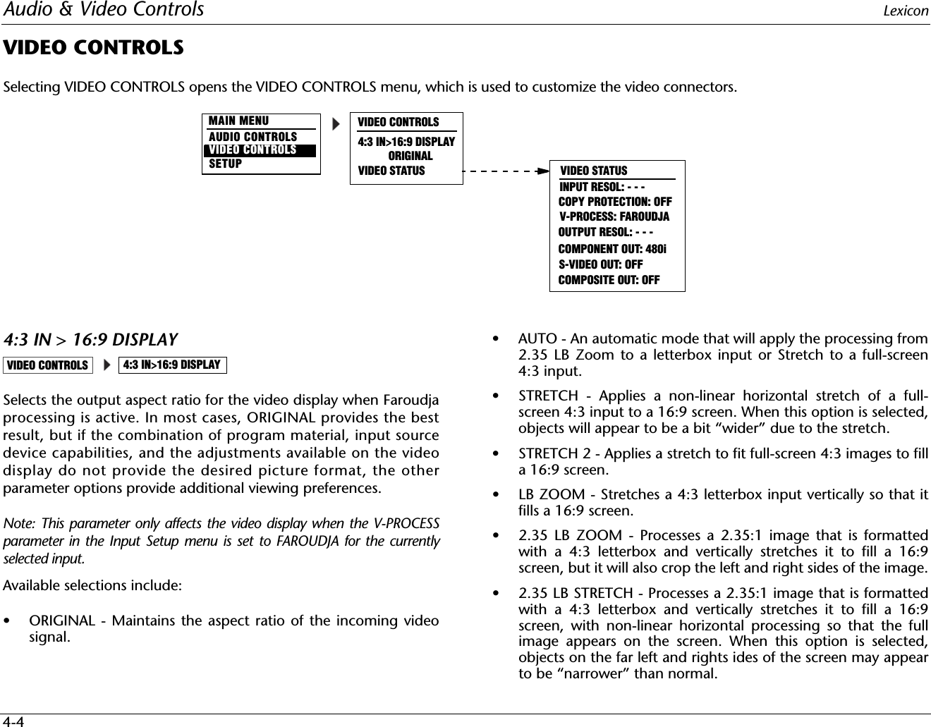
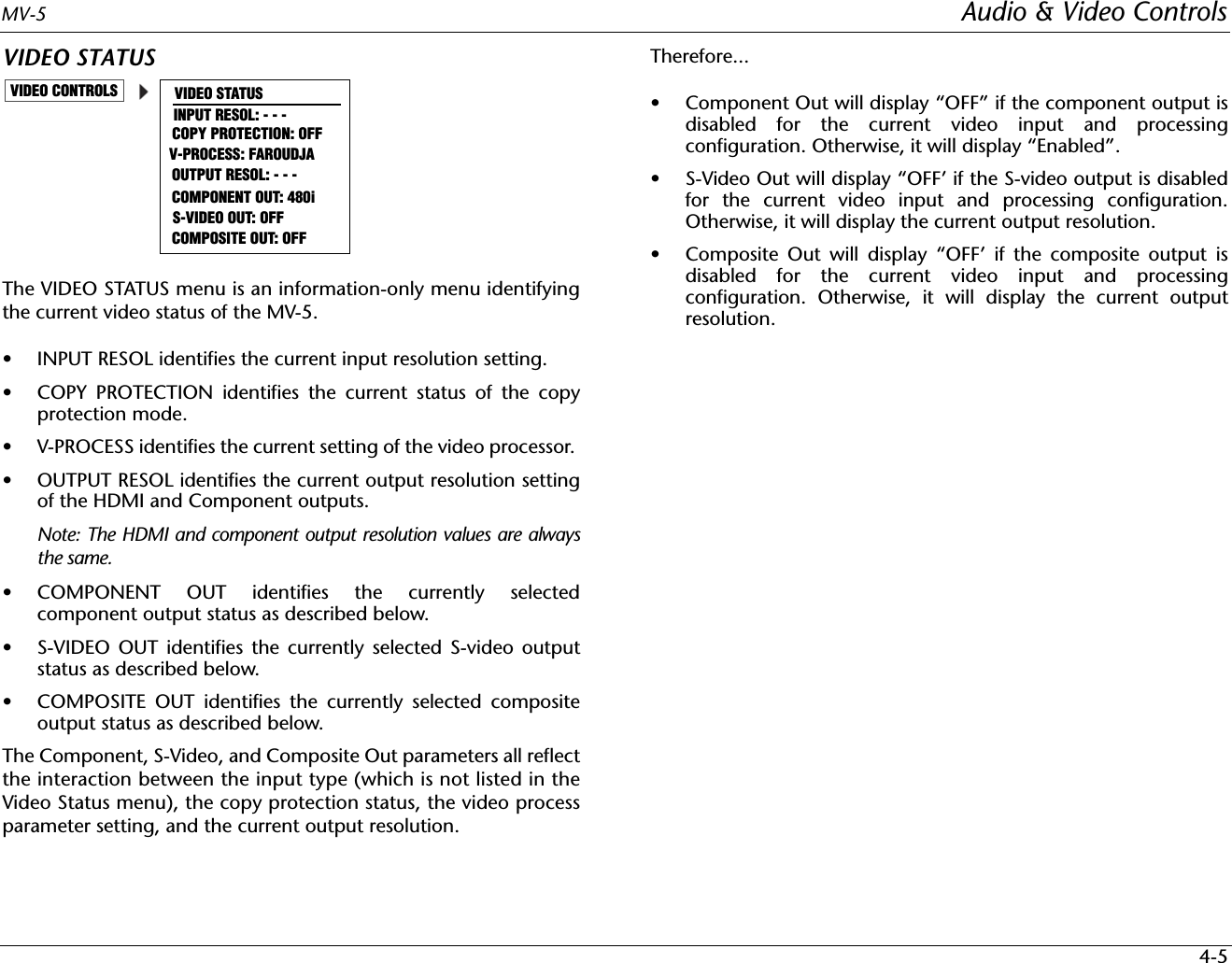
User Manual
Discussion / Help
Navigation