Woori Technology MV-5 AV Processor Preamplifier User Manual MV5
Woori Technology Inc AV Processor Preamplifier MV5
User Manual

MV-5 Processor
User Guide

Lexicon Inc.
3 Oak Park Drive
Bedford, MA 01730-1413 USA
Tel 781-280-0300
Fax 781-280-0490
www.lexicon.com
Customer Service
Telephone: 781-280-0300
Sales Fax: 781-280-0495
Service Fax: 781-280-0499
Part No. 070-18137 | Rev 0 | 6/07
Lexicon, “Logic 7”, and the L7 logo are registered trademarks of Harman International Industries, Inc.
Manufactured under license from Dolby Laboratories. “Dolby”, “Pro Logic”, and the double-D symbol are trademarks of Dolby
Laboratories.
“DTS” and “DTS-ES | Neo:6” are registered trademarks of DTS, Inc. and “96/24” is a trademark of DTS, Inc.
“Faroudja” and “DCDi by Faroudja” are trademarks of Genesis Microchip, Inc.
“HD-DVD” is a trademark of the DVD Format/Logo Licensing Corporation (DVD FLLC).
“HDMI”, the HDMI logo, and “High-Definition Multimedia Interface” are trademarks or registered trademarks of HDMI Licensing
LLC.
“iPod” and “iTunes” are trademarks of Apple Computer, Inc.
“SACD” is a trademark of Sony Electronics, Inc.
“Windows” is a trademark of Microsoft, Inc.
“TOSLINK” is a trademark of Toshiba America Electronic Components, Inc.
“DLP” and “Digital Light Processing” are trademarks of Texas Instruments, Inc.
Other company and product names may be trademarks of the respective companies with which they are associated.
© 2007 Harman Specialty Group and Harman International Industries, Incorporated. All rights reserved.
Lexicon is a division of Harman Specialty Group, which is a wholly-owned company of Harman International, Inc.
This document should not be construed as a commitment on the part of Harman Specialty Group. The information it contains is
subject to change without notice. Harman Specialty Group assumes no responsibility for errors that may appear within this
document.

Introduction Lexicon
ii
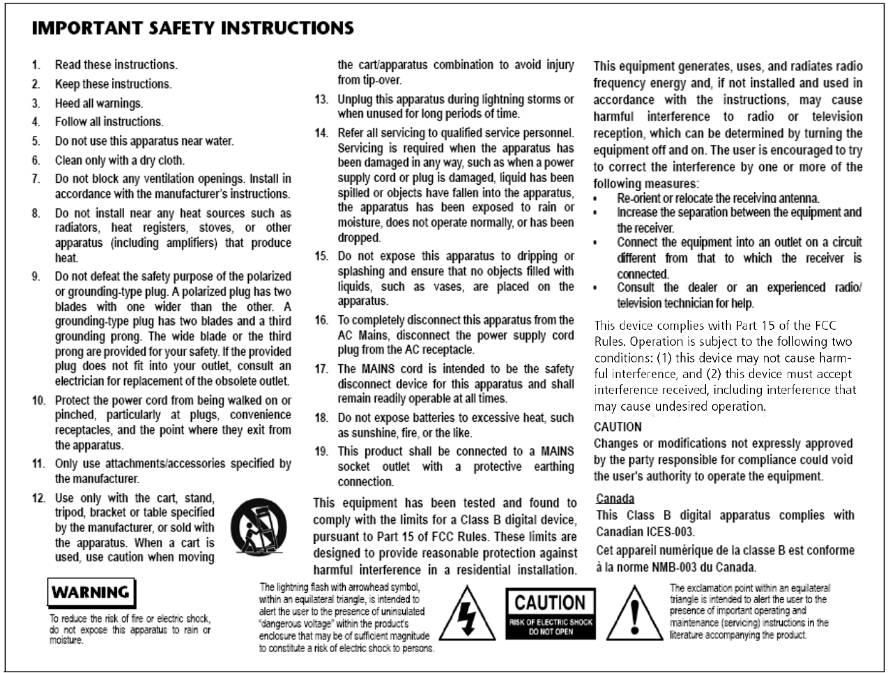
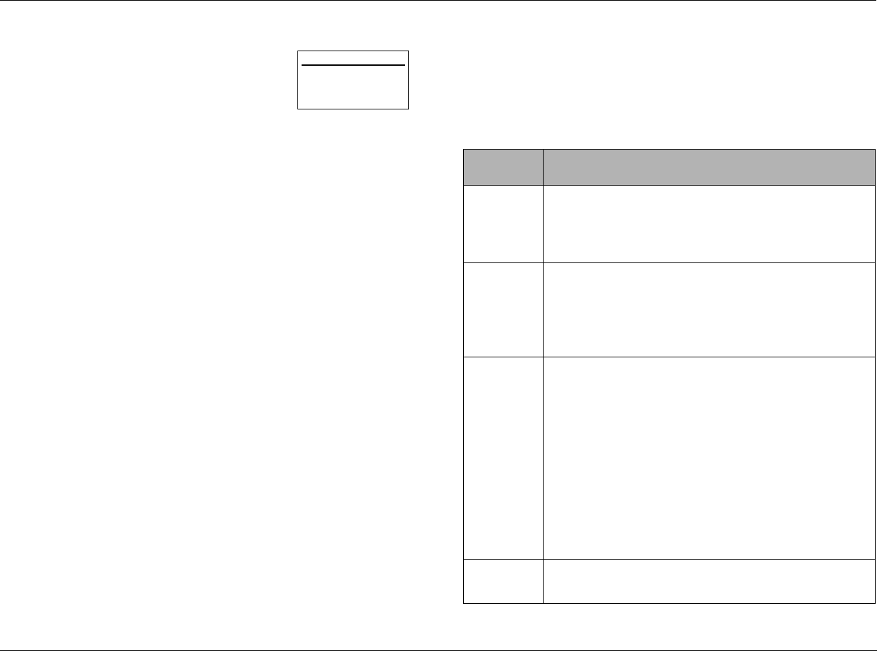
DOCUMENTATION CONVENTIONS
This document contains general safety, installation and operation instructions for the MV-5 Processor. It is important to read this user guide
before attempting to use the product. Pay particular attention to safety instructions.
All graphics of the product are included for reference only and may not completely reflect the physical product that is shipped.
The following symbols are used in the document:
Appears on the component to indicate the
presence of uninsulated, dangerous voltage
inside the enclosure – voltage that may be
sufficient to constitute a risk of shock.
Appears on the component to indicate important
operating and maintenance instructions in the
accompanying literature.
Calls attention to a procedure, practice,
condition or the like that, if not correctly
performed or adhered to, could result in injury or
death.
Calls attention to a procedure, practice,
condition or the like that, if not correctly
performed or adhered to, could result in damage
or destruction to part or all of the product.
Calls attention to information that is essential to
highlight.
WARNING
CAUTION!
Note:

MV-5 Introduction
iii
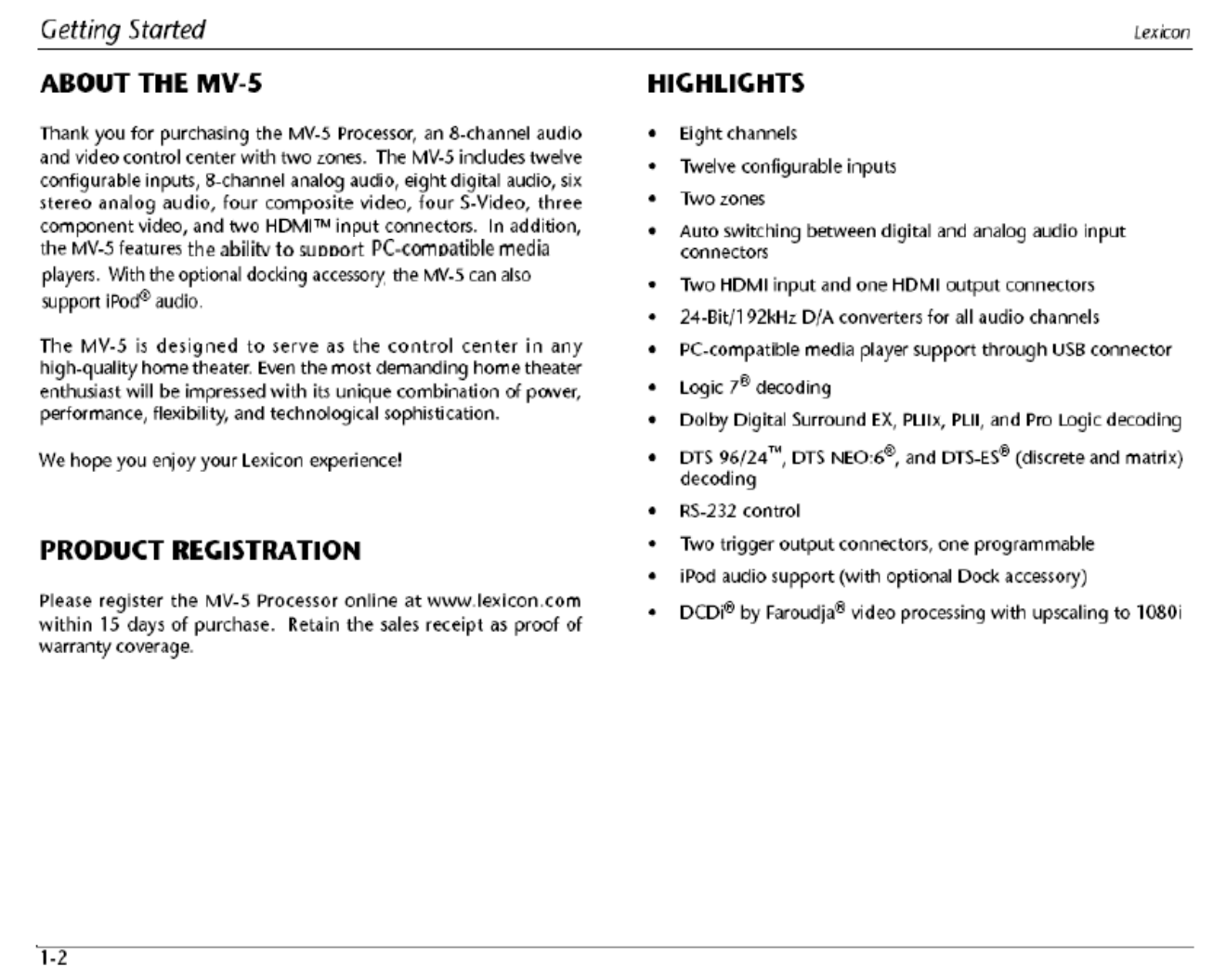
Getting Started
About the MV-5 ........................................................................ 1-2
Product Registration .................................................................. 1-2
Highlights ................................................................................. 1-2
What’s in the Box......................................................................1-3
Available Options ......................................................................1-3
Optional D-1 Dock Accessory ................................................ 1-3
Optional RF-1 Receiver .......................................................... 1-3
Installation Considerations......................................................... 1-4
Remote Control Battery Installation ........................................... 1-4
Basic Operation
Front-Panel Overview ................................................................2-2
Rear Panel Overview.................................................................. 2-5
PC & Dock Overview................................................................. 2-8
Remote Control Overview ......................................................... 2-8
Operation Considerations ...................................................... 2-8
MV-5 Menu Overview ........................................................... 2-9
Menu Navigation .................................................................. 2-9
Remote Control Buttons ...................................................... 2-10
Menu Options ..................................................................... 2-11
Menu Item Selection ........................................................... 2-11
Remote Control Light Button .............................................. 2-11
Command Matrix ............................................................... 2-11
Setup
Setup ........................................................................................ 3-2
Display Setup ............................................................................ 3-3
Speaker/EQ Setup ..................................................................... 3-6
Rear Amp ............................................................................... 3-7
Manual ................................................................................. 3-7
Semi Autocal ......................................................................... 3-7
Full Autocal ........................................................................... 3-7
Manual Speaker Setup............................................................... 3-9
Speakers Menu .................................................................... 3-10
Speaker Distances Menu ..................................................... 3-11
Output Levels Menu ............................................................ 3-12
Input Setup ............................................................................. 3-14
Advanced Video .................................................................. 3-20
Listening Modes...................................................................... 3-23
Selecting a Listening Mode ................................................. 3-23
DTS + Dolby Listening Modes ............................................. 3-23
Available Listening Modes ................................................... 3-24
Listening Mode Descriptions ............................................... 3-27
5.1-channel & 7.1-channel Direct Inputs ............................. 3-28
DTS & Dolby Status Displays ............................................... 3-29
Surround Configuration .......................................................... 3-30
Dolby Configuration ............................................................... 3-32
Mute Levels............................................................................. 3-33
Power On Settings .................................................................. 3-33
Audio & Video Controls
Audio Controls .......................................................................... 4-2
Video Controls .......................................................................... 4-4
PC & Dock Controls
PC & Dock Overview................................................................. 5-2
PC Controls............................................................................... 5-2
Setting Up to Play ................................................................. 5-2
Playing PC Media .................................................................. 5-3
Dock Functionality .................................................................... 5-4
Connecting the Dock to the MV-5 ........................................ 5-4
Selecting the correct iPod insert ............................................ 5-4
Docking the iPod .................................................................. 5-5
Dock 2-line Display Characteristics ........................................ 5-5
Controlling the iPod with the MV-5 ...................................... 5-6
Charging the iPod ................................................................. 5-7
Removing the iPod ................................................................ 5-7
Zone 2 iPod Controls ............................................................ 5-7

Introduction Lexicon
iv
Troubleshooting & Maintenance
Troubleshooting ........................................................................6-2
MV-5 Error Messages.................................................................6-6
Video Error Messages .............................................................6-6
Autocal Error Messages .......................................................... 6-7
Video Resolutions Table .............................................................6-9
Routine Maintenance...............................................................6-11
Restore Factory Default Settings...............................................6-11
Appendix A
Specifications.............................................................................A-2
Declaration of Conformity .........................................................A-4
Appendix B
Main Menu: Audio Controls ......................................................B-2
Main Menu: Video Controls.......................................................B-2
Main Menu: Setup.....................................................................B-3
Setup Menu: Display Setup ................................................... B-4
Setup Menu: Surround Config ............................................... B-4
Setup Menu: Speaker/EQ Setup ............................................. B-5
Setup Menu: Input Setup ...................................................... B-6
Appendix C
Remote Control Programming.................................................. C-2
Remote Control Light Button .................................................C-2
Transmitting Icon ..................................................................C-2
Setting Up the Remote Control .............................................C-3
Lock Feature ..........................................................................C-6
Advanced Customizing Tools .................................................C-6
Erasing Commands .............................................................C-13
Restoring Factory Default Settings .......................................C-14
Optional RF-1 Receiver ........................................................... C-14
Using the 3-Digit Code Library ............................................... C-15
Three-digit Pre-programmed Codes ....................................C-15
Appendix D
Installation Worksheet ............................................................ D-2
3-Digit Pre-programmed Codes Worksheet .............................. D-6
Index

1
Getting Started
About the MV-5 ......................................................................... 1-2
Product Registration................................................................... 1-2
Highlights .................................................................................. 1-2
What’s in the Box....................................................................... 1-3
Available Options ....................................................................... 1-3
Optional D-1 Dock Accessory .................................................................... 1-3
Optional RF-1 Receiver .............................................................................. 1-3
Installation Considerations.......................................................... 1-4
Remote Control Battery Installation ............................................ 1-4

MV-5 Getting Started
1-3
WHAT’S IN THE BOX
The following accessories are included with the MV-5 Processor:
One User Guide (this document)
One Remote Control
Four AAA Batteries (for use with Remote Control)
One Microphone
One Microphone Extender Rod
One 115V Power Cord
Two 220V Power Cords
AVAILABLE OPTIONS
The following accessories are available for purchase as options to
the MV-5 Processor:
• D-1 Dock Station, Part No. 021-18138, allows an iPod to be
connected and controlled by the MV-5 Processor.
• RF-1 RF Receiver Part No. 021-18005, allows the remote control
to operate via RF (Radio Frequencies) and hence gives the
remote a broader operating range.
OPTIONAL D-1 DOCK ACCESSORY
The D-1 Dock optional accessory allows you to enter a new world of
listening enjoyment made possible by combining the increased
storage capacity and playback flexibility of an iPod® (not included)
with the sonic power of your Lexicon receiver. Operation is easy,
you can use your Lexicon remote control or the front panel Tuner
section of the MV-5 to access and control your iPod selections. Just
one simple connection and you’re ready to go!
• Single connection to your Lexicon receiver
• Plays audio from an iPod through your Lexicon receiver
• Controls your iPod through your Lexicon receiver
• Easy track selection with on-screen navigation
• Charges the iPod
OPTIONAL RF-1 RECEIVER
The optional RF-1 Receiver provides a boost to the Lexicon remote
control, allowing multi-directional RF signals to pass through walls,
doors, and floors - both indoors and outdoors. The RF-1 Receiver used
in conjunction with the MV-5 Processor allows you to control
components that are completely out-of-sight, up to 100-feet away.
Since the RF-1 Receiver picks up multi-directional radio frequency
signals, the MV-5 remote control no longer needs to be pointed
directly at the component to control it. Now you can close your
entertainment center doors, hide your components, and still control
them with ease.
The RF-1 Receiver accessory requires no setup to the Lexicon remote
control in order for the feature to work - you need only plug the
optional device into the IR port of the MV-5 rear panel. Every time a
command is sent from the remote control, it sends both a standard IR
and an RF signal. The RF-1 Receiver automatically receives the remote’s
radio signals and translates them into the infrared commands that
control the components.

Getting Started Lexicon
1-4
INSTALLATION CONSIDERATIONS
The MV-5 requires special care during installation to ensure optimal
performance. Pay particular attention to instructions below and to
other precautions that appear throughout this user guide.
DO install the MV-5 on a solid, flat, level surface such as a table or
shelf.
DO select a dry, well-ventilated location out of direct sunlight.
DO NOT expose the MV-5 to high temperatures, humidity, steam,
smoke, dampness or excessive dust. Avoid installing the MV-5 near
radiators or stacking the MV-5 over other heat-producing
equipment such as a power amplifier.
DO NOT place the MV-5 on a thick rug or carpet, or cover the RV-5
with a cloth, as this might prevent proper cooling.
DO NOT place the MV-5 on a windowsill or any location exposed
to direct sunlight.
DO NOT obstruct the front-panel IR receiver window. The remote
control must be in line of sight with the IR receiver for proper
operation (unless using the optional RF-1 RF Receiver).
DO NOT install the MV-5 on a surface that is unstable or unable to
support all four feet.
CAUTION!
Before moving the MV-5, power the unit off using the
rear-panel power switch and unplug the power cord from
the wall outlet.
REMOTE CONTROL BATTERY
INSTALLATION
The remote control requires four AAA batteries. The batteries
should be replaced as needed. Alkaline batteries, which last longer
without leaking, are recommended. When battery power is low, the
remote control enters a low-voltage condition, preventing it from
operating the RV-5. When this occurs, replace the batteries. Normal
operation will resume when new batteries are installed.
To replace the remote control batteries:
1. Locate the battery compartment on the back of the remote
control. Press the tab and lift the cover away from the remote
control.
2. Remove old batteries, if applicable.
3. Observing the proper polarity, insert four AAA batteries.
4. Align the cover over the battery compartment and gently press
down until it snaps back into place.
5. Properly dispose of the old batteries (if applicable).
Note: The Remote Control will not lose any custom settings if the batteries
run out. All custom settings are stored in non-volatile FLASH memory.

2
Basic Operation
Front-Panel Overview ................................................................. 2-2
Rear Panel Overview................................................................... 2-5
PC & Dock Overview.................................................................. 2-8
Remote Control Overview .......................................................... 2-8
Operation Considerations.......................................................................... 2-8
MV-5 Menu Overview ............................................................................... 2-9
Menu Navigation ...................................................................................... 2-9
Remote Control Buttons.......................................................................... 2-10
Menu Options......................................................................................... 2-11
Menu Item Selection ............................................................................... 2-11
Remote Control Light Button .................................................................. 2-11
Command Matrix ................................................................................... 2-11
Lexicon
2-2
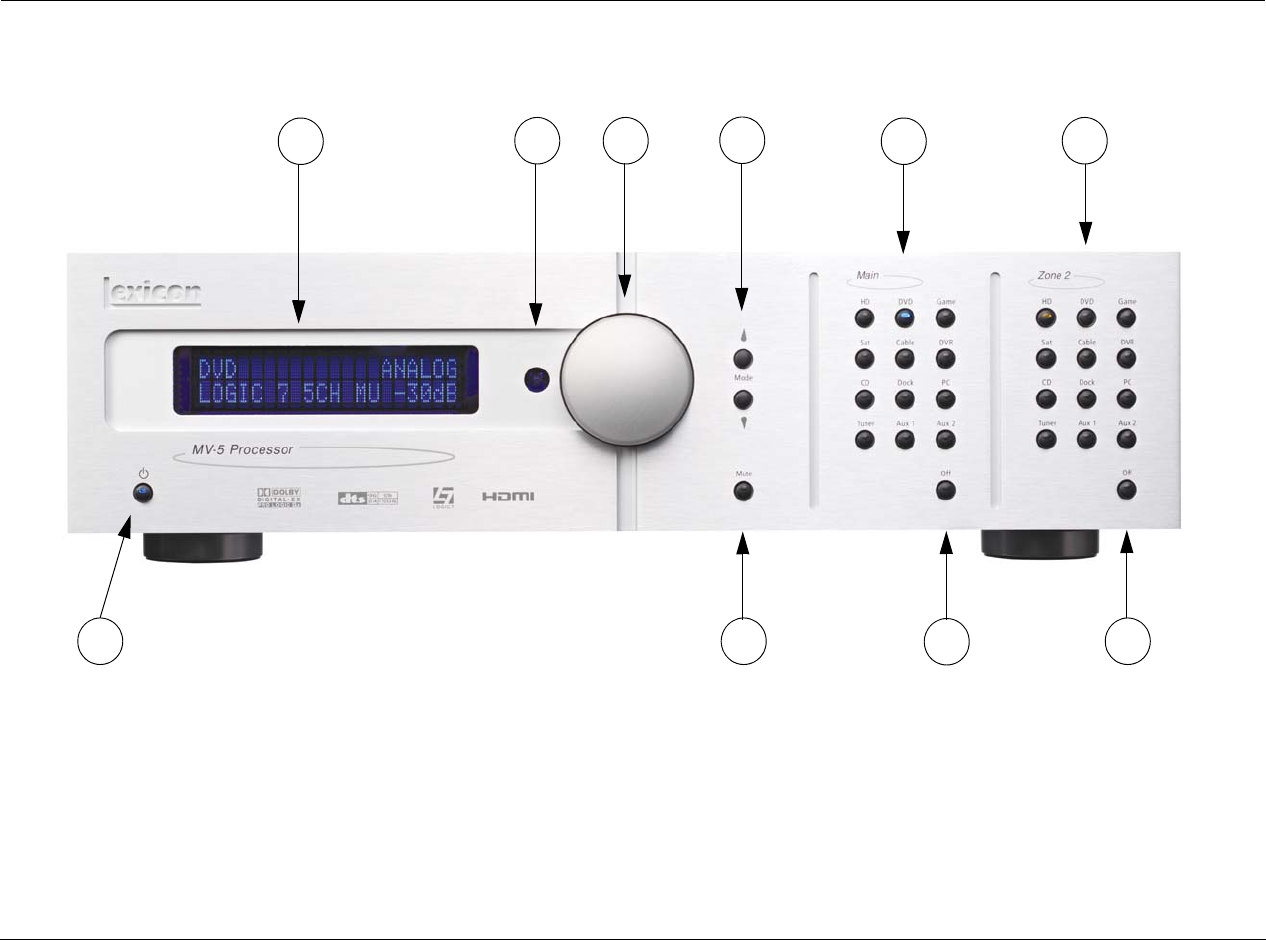
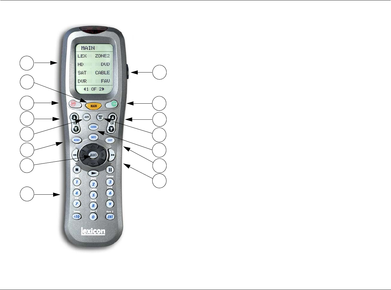
FRONT-PANEL OVERVIEW
The MV-5 is shown below. The numbers in the front-panel illustration correspond with the numbered items in the text.
1. Front Panel Display
2. IR Receiver
3. Volume Knob
4. Mode and Buttons
5. Main Zone Input Selection Buttons
6. Zone 2 Input Selection Buttons
7. Zone 2 Off Button
8. Main Zone Off Button
9. Mute Button
10. Standby Button
1 2 3 5 6
4
10 9 8 7

MV-5
2-3
1 FRONT-PANEL DISPLAY
Use the front-panel display to view the current input source, input
type, listening mode, and volume level. If the built-in tuner is active,
the display will show the frequency band, selected frequency,
preset location, listening mode, and volume level. The 2 x 20
character display also functions as a display for messages and
menus, one line at a time.
2 IR RECEIVER
The IR receiver receives infrared commands from the MV-5 remote
control. Blocking the IR receiver will prevent the remote control
from functioning properly (unless using the optional RF-1 RF
Receiver).
3 VOLUME KNOB
Use the volume knob to adjust the volume level. The adjustable volume
range is -80 dB to +10 dB in 1 dB increments.
Note: The maximum volume level may be lower than +10 dB due to the
output level settings of the speakers. Refer to Section 3: Setup for more
information on setting the speaker output levels.
To adjust the Main Zone volume level:
Rotate the volume knob clockwise to increase or counter-clockwise
to decrease the volume level in 1dB increments. The current
volume level is indicated on the bottom right side of the 2-line front
panel display.
To adjust the Zone 2 volume level:
1. Press and hold the front-panel Zone 2 input selection button that
corresponds with the current input source. For instance, if DVD is
the current Zone 2 input source, press and hold the DVD input
selection button in the Zone 2 area of the front panel.
2. While holding down the input Zone 2 button, rotate the volume
knob clockwise to increase the volume or counter-clockwise to
decrease the volume. On the front panel 2-line display, the
bottom left side displays that Zone 2 is selected and the bottom
right side indicates the current volume level.
Note: If you attempt to set the volume higher than the maximum or lower
than the minimum volume levels, the volume parameter flashes on the
2-line front panel and OSD (On-Screen Display) displays.
4 MODE and BUTTONS
Use the Mode buttons to scroll to the previous () or next ()
available listening mode. Scrolling the mode button reveals the
entire list of listening modes available for the currently selected
input and mode family. For more information on selecting listening
modes, refer to Section 3: Setup.
5 MAIN ZONE INPUT SELECTION BUTTONS
Individually selects each of the twelve inputs available in the Main
Zone. When an input is selected, a blue LED lights in the
corresponding input selection button. When the Main Zone is
deactivated, pressing a Main Zone input selection button activates
the corresponding input in the Main Zone.
When the MV-5 is in Standby, pressing a Main Zone input selection
button powers on the MV-5, selects the input in the Main Zone,
and turns off Zone 2.

Lexicon
2-4
6 ZONE 2 INPUT SELECTION BUTTONS
Individually selects each of the twelve inputs available in Zone 2.
When an input is selected, an amber LED lights on the
corresponding input selection button. When Zone 2 is deactivated,
pressing a Zone 2 input selection button activates the
corresponding input in Zone 2.
When the MV-5 is in Standby, pressing a Zone 2 input selection
button powers on the MV-5, selects the input in Zone 2, and turns
off the Main Zone.
7 ZONE 2 OFF BUTTON
Deactivates Zone 2. When Zone 2 is off, the Zone 2 OFF button on
the front panel lights red.
8 MAIN ZONE OFF BUTTON
Deactivates the Main Zone. When the Main Zone is off, the Main
Zone OFF button on the front panel lights red.
Note: Activating the Main Zone off button on the front panel turns off the
audio, however the video continues to be output through both the analog
and HDMI video outs. If using the HDMI Video In connection, only the
HDMI video is output. If the analog Video In is used, then both analog
and HDMI video is output. Main Zone OSD menus are also still available.
9 MUTE BUTTON
Mutes the Main Zone and Zone 2 volumes. Press the MUTE button to
mute the Main Zone volume level; “MUTE ON” appears in the 2-line
and OSD displays, and the MUTE button lights red. Press the MUTE
button again to restore the volume to its original level; the LED in the
MUTE button turns off. If a front panel Zone 2 input button is held
down, then pressing the MUTE button on the front panel will mute the
Zone 2 output and the MUTE button lights green.
Pressing the volume button once on the remote while the volume is
muted, turns off mute. Pressing and holding the Volume button,
while the sound is muted, resets to the original pre-mute volume
level and then increases or decreases the volume from that point,
turning off mute.
The LED in the MUTE button lights red when the Main Zone mute is
active, green when the Zone 2 mute is active, and amber when
both Zones are muted. The volume can also be muted by using the
MUTE button on the remote control, which functions in the same
manner.
10 ON/STANDBY BUTTON
Toggles the MV-5 between On and Standby. The rear panel Power
Switch must be set to the ON position for the Standby button to be
active. When the MV-5 is in the standby mode, pressing the
Standby button turns the unit on and changes the light in the
Standby button from red to blue. Power is still supplied to the MV-
5 when standby mode is activated.
When the rear panel Power Switch is initially set to the ON position,
the MV-5 automatically enters the standby mode.
Note: When taken out of standby, the MV-5 activates the Zones that were
active in the previous operating session.
Lexicon
2-5
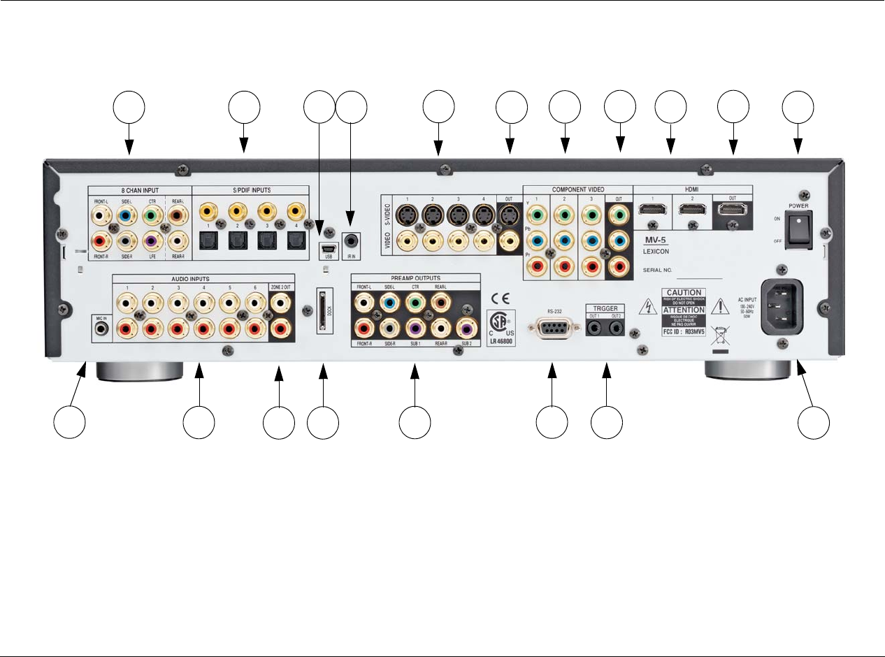
REAR PANEL OVERVIEW
The MV-5 rear panel is shown below. The numbers in the rear-panel illustrations correspond with the numbered items in the text.
1. 8-CH Analog Audio Input Connectors
2. Digital Audio Input Connectors
3. USB Connector
4. IR In Connector
5. S-Video/Composite Input Connectors
6. S-Video/Composite Ouput Connectors
7. Component Video Input Connectors
8. Component Video Output Connector
9. HDMI Input Connectors
10. HDMI Output Connector
11. Power Switch
12. AC Input Connector
13. Trigger Output Connectors
14. RS-232 Connector
15. Preamplifier Outputs
16. Dock Connector
17. Zone 2 Audio Output Connectors
18. Stereo Analog Audio Input Connectors
19. Microphone Input Connector
19
1 2 5 6
3
18 15
16 13
7 8
17
9 10 11
12
14
4

Lexicon
2-6
CAUTION!
Never make or break connections to the MV-5 unless the
MV-5 and all associated components are powered off.
1 8-CH ANALOG AUDIO INPUT CONNECTORS
Provides 8-channel analog audio inputs via eight connectors
labeled Front L/R, Center, LFE, Side L/R and Rear L/R. These inputs
are used to connect source devices such as high-resolution DVD
players, DVD-Audio, or SACD players with discrete analog audio
outputs. Depending on the source device in use, all eight
connectors may be used, though only the Front L/R, Center, Side L/
R, and LFE are required for 5.1 audio signals.
2 DIGITAL AUDIO INPUT CONNECTORS
Provides digital audio input via four S/PDIF optical (TOSLINK) and
four S/PDIF coaxial (RCA) input connectors. Connectors are
compatible with PCM, Dolby Digital, and DTS(-ES) sources.
3 USB CONNECTOR
Provides a USB port to connect to a PC-compatible computer,
enabling the user to listen to audio from the computer through the
MV-5 Processor. The USB connector port is a “mini B” connector
and requires a USB cable (not included). See Section 5: PC & Dock
Controls for more information on the playback of computer audio.
4 IR IN CONNECTOR
Accepts input of IR signals from infrared distribution equipment.
One 3.5mm jack that accepts a stereo plug (Tip/Ring/Sleeve
connection) or mono plug (Tip/Sleeve connection) is available.
5 S-VIDEO/COMPOSITE INPUT CONNECTORS
Provides the S-Video & Composite analog video inputs. Four
composite video connectors labeled 1 to 4 and four S-Video
connectors labeled 1 to 4 are available.
6 S-VIDEO/COMPOSITE OUTPUT CONNECTORS
Provides the S-Video & Composite video outputs. One composite
video connector and one S-Video connector are available.
7 COMPONENT VIDEO INPUT CONNECTORS
Provides inputs that can be used with any source device that is
equipped with analog Y/Pr/Pb or RGB component video outputs.
Three inputs, labeled Component Video 1 to 3, are supplied.
8 COMPONENT VIDEO OUTPUT CONNECTORS
Provides one component output that can be used with any device that
is equipped with analog Y/Pr/Pb or RGB component video intputs.
9 HDMI INPUT CONNECTORS
Provides two HDMI inputs for devices such as a DVD player or
HDTV tuner.
10 HDMI OUTPUT CONNECTOR
Provides one HDMI output for HDMI-equipped video monitors.

MV-5
2-7
11 POWER SWITCH
Use the Power Switch to connect or disconnect power from the AC
Input connector to the MV-5 Processor. When the MV-5 is powered
on, the front-panel Standby button or remote control ON & OFF
buttons can be used to activate and deactivate standby mode. When
the MV-5 is powered off, the standby and ON modes are not
available.
12 AC INPUT CONNECTOR
Provides power to the MV-5 through the supplied power cord.
13 TRIGGER OUTPUT CONNECTORS
Provides a 12V DC output to control connected components. Two
trigger output connectors are available as 3.5 mm mono mini
phone jacks. The OUT 1 connector, or power trigger, is not
configurable; it is activated when the MV-5 is powered on, and
deactivated when the MV-5 is powered off, either from the rear
panel or by putting the MV-5 into Standby mode. The OUT 2
connector can be configured independently for each input, refer to
Section 3: Setup for more information on how to configure the OUT
2 trigger.
Note: The OUT 2 trigger is referred to as “TRIGGER 2” in the Input Setup
menu.
14 RS-232 CONNECTOR
The RS-232 serial connector provides serial remote control through a
standard RS-232 connection. Refer to the Lexicon website
(www.lexicon.com) for more details on controlling the MV-5 Processor
via the RS-232 connection.
15 PREAMPLIFIER OUTPUTS
Provides outputs for optional, external power amplifiers for
applications that require them.
16 DOCK CONNECTOR
Provides an interface for an iPod, which can then be accessed
through the MV-5. To use this feature, the D-1 Dock option must
be installed to the DOCK connector. With a compatible iPod
connected to the MV-5, selecting the DOCK input allows you to
play audio files from the iPod. You can navigate the iPod using the
MV-5 remote and view any of the iPod menus through the MV-5
front panel and any video monitor connected to the MV-5. For
more information on the Dock option and how to use your MV-5
with an iPod, refer to Section 5: PC & Dock Controls.
17 ZONE 2 AUDIO OUTPUT CONNECTORS
Provides preamplifier audio outputs for Zone 2.
18 STEREO ANALOG AUDIO INPUT CONNECTORS
Provides stereo analog audio inputs. Six stereo analog audio input
connectors labeled 1 to 6 are available.
19 MICROPHONE INPUT CONNECTOR
Provides a microphone input for speaker calibration. The
microphone input is only for use with the supplied microphone
during the auto-calibration process.

Lexicon
2-8
PC & DOCK OVERVIEW
The PC & Dock inputs are the only “hard-wired” inputs in the MV-5
Processor. Unlike the other inputs, both have very specific
functionality.
The PC input is tied to the USB input on the rear panel and is for use
with media player software. The Dock input is for use with the
optional D-1 Dock accessory and is tied to the DOCK input on the
rear panel. This input is only for use with iPod players.
While both of these inputs have devoted Remote Control menu
controls, there are NO front panel controls for use with the PC and
DOCK inputs.
For more information about the PC and Dock operation, refer to
Section 5: PC & Dock Controls.
REMOTE CONTROL OVERVIEW
The MV-5 Processor remote control provides full operation of the
MV-5, including commands, such as menu navigation, that are not
available from the front panel. It is also designed to provide control
for the entire home theater system. This section provides a brief
overview of the remote control functions used to control the MV-5
Processor. For detailed universal remote control operation,
programming instructions, and manufacturing codes, refer to
Appendix C.
OPERATION CONSIDERATIONS
The following factors can improve or impede remote control
operation.
Note the following before operating the MV-5 remote control:
• The remote control must be in line-of-sight with the front panel
IR receiver (unless using the optional RF-1 RF Receiver).
Eliminate obstructions between the remote control and the IR
receiver. The remote control may become unreliable if strong
sunlight or fluorescent light shines on the IR receiver.
• For optimal performance, position the remote control at a
30-degree angle no more than 40 to 60 feet (12.2m to 18.3m)
from the MV-5. Placing the MV-5 inside a smoked glass cabinet
will reduce the remote control range.
• Remote controls for different components can interfere with
one another. Avoid using remote controls for different
components at the same time.
• Remote-control batteries should be replaced as needed.
MV-5
2-9
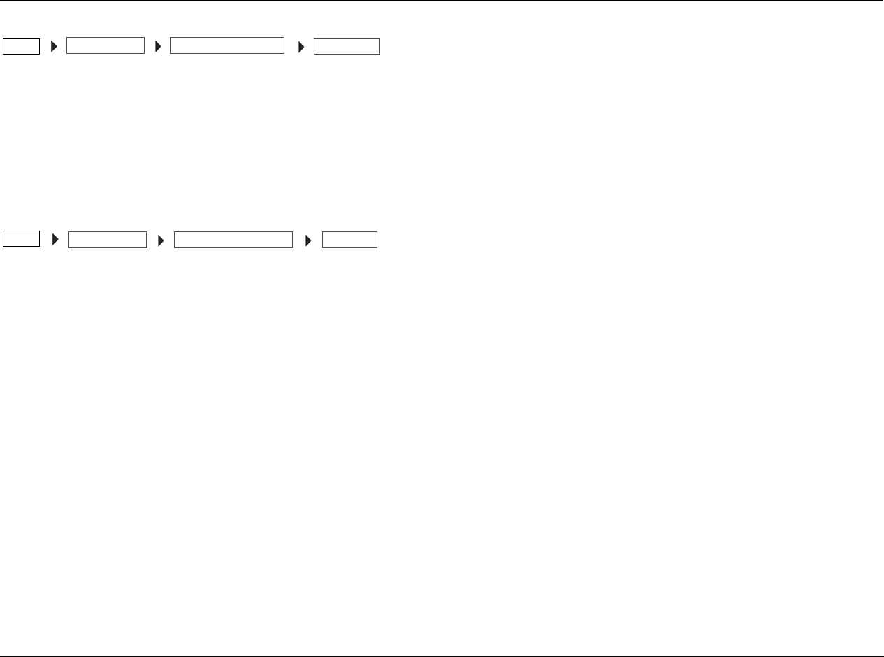
MV-5 MENU OVERVIEW
When the remote control touch screen is in the
“LEX”, “TUNER”, or “ZONE 2” menus, pressing
MENU or SELECT on the Remote Control
accesses the menu controls for the MV-5
Processor. The MAIN MENU is the root
directory of the MV-5 menu tree and has three
branches: AUDIO CONTROLS, VIDEO
CONTROLS, and SETUP.
Note: When the MV-5 menu structure is entered, most front panel buttons
and the remote control buttons are disabled until the menu structure is
exited. The exceptions are the Volume Knob and Standby Button on the
front panel and the remote control Volume, Mute, and OFF buttons. Note
also that the disabled condition of the remote control only affects the
“LEX”, “TUNER”, and “ZONE 2” menu layers.
MENU NAVIGATION
Use the remote control arrow buttons to navigate the MV-5 menu
structure, shown in detail in Appendix B. The Command Matrix
Table indicates the navigation commands that the remote control
buttons perform when the MV-5 command bank is activated by
selecting the “LEX”, “TUNER”, or “ZONE 2” options on the remote
control touch screen.
MAIN MENU
AUDIO CONTROLS
VIDEO CONTROLS
SETUP
Arrow Navigation Functions
When a menu is open, press the remote control
Menu arrow to select the highlighted menu
parameter. The menu parameter will blink to
indicate that it is selected.
When a menu is open, press the Menu arrow to
close the menu and, in most cases, open the
previous menu. Subsequent presses continue to
close the current menu and open the previous
menu until the MAIN MENU is closed.
When a menu is open, press the Menu and
arrow buttons to scroll upward and downward
through the complete list of menu parameters. The
highlighted menu item appears in the front panel
display. All menu items appear in the OSD. The
cursor automatically wraps to the next menu
parameter when the first or last menu item is passed.
When a menu parameter is selected and blinking,
press the Menu and arrow buttons to scroll
through the available parameter options.
SELECT Press the SELECT button to open the menu structure,
open a menu branch, or select a menu parameter.
Lexicon
2-10
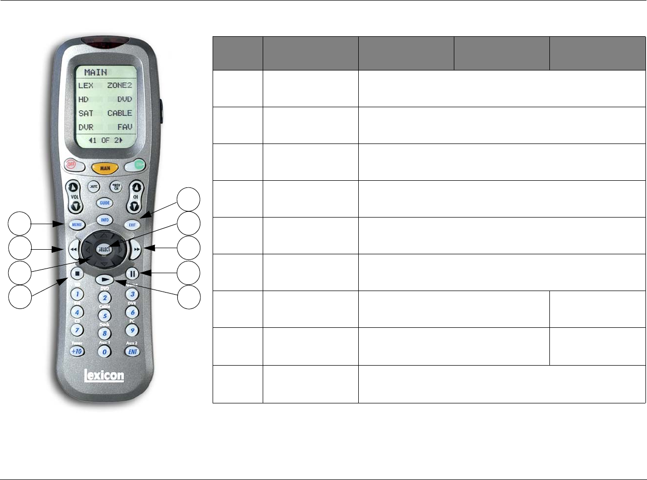
REMOTE CONTROL BUTTONS
1. Touch Screen (component and function buttons)
2. MAIN remote control touch screen menu
3. OFF
4. VOLUME (+/-)
5. MUTE
6. MENU
7. SELECT & Navigation (left, right, up, down & center press)
8. MV-5 Input buttons/ Number Keypad & Enter
9. LIGHT
10. ON
11. CHANNEL/Listening Mode (+/-)
12. Previous Channel
13. GUIDE & INFO
14. EXIT
15. Transport functions (PLAY, STOP, RW, PAUSE, and FF) for VCR,
DVD and CD
Note: The number call-outs on the figure above
correlate with the numbers listed to the right.
1
9
2
3 10
4 11
5 12
6
7
13
14
8
15

MV-5
2-11
MENU OPTIONS
Selecting a menu option can open another menu within the menu
structure. For example, selecting SETUP from the MAIN MENU opens
the SETUP menu.
MENU ITEM SELECTION
Use the remote control Menu arrows to navigate menus.
To select a menu item on the open menu:
1. Press the remote control and arrows to highlight the desired
menu item.
2. When the desired menu item is highlighted, press the Menu
arrow to select the highlighted item. If an option is selected,
another menu opens. When an adjustable parameter is selected,
the current selection will blink to indicate that it is selected. Use
the and arrows to scroll through the available options for the
selected parameter. When the desired parameter option is
highlighted, press the cursor on the remote control to select the
option.
REMOTE CONTROL LIGHT BUTTON
The remote control is fully back lit, making it very useful in low
lighting conditions. Press the LIGHT button on the right side of the
remote to back light all of the buttons and the LCD touch screen.
To turn off the back light, press the LIGHT button again or wait. Ten
seconds after the last button is pressed, the back light will
automatically shut off.
COMMAND MATRIX
The command matrix table, starting on the next page, lists the
commands that each remote control button performs in each menu
setting.
Note: A brief description of each function is given in the table but refer to
the Table of Contents for additional information on each function. For
additional information on using and programming the remote control,
refer to Appendix C.
MAIN MENU
AUDIO CONTROLS
VIDEO CONTROLS
DISPLAY SETUP
SPEAKER/EQ SETUP
INPUT SETUP
SURROUND CONFIG
DOLBY CONFIG
MUTE LEVELS
POWER ON SETTINGS
SETUP
SETUP
Lexicon
2-12
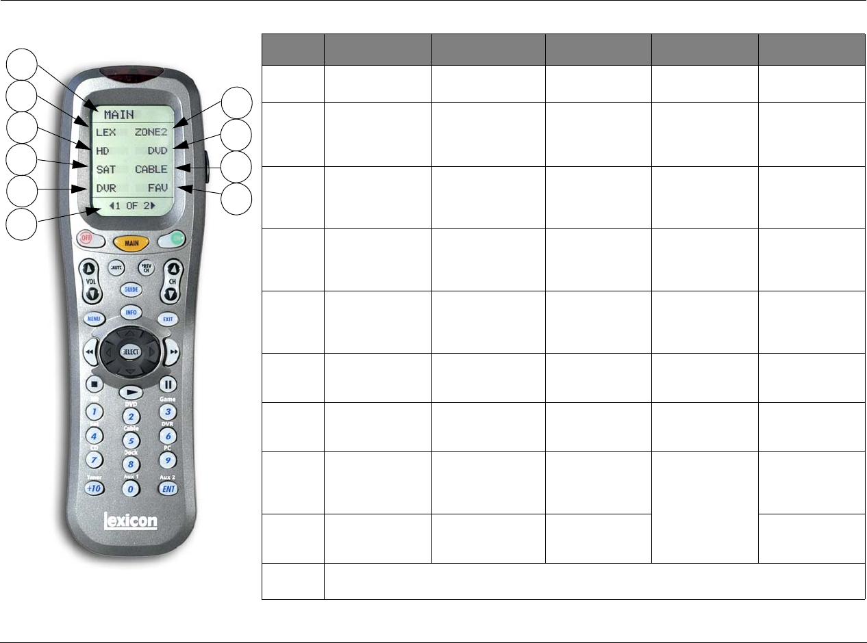
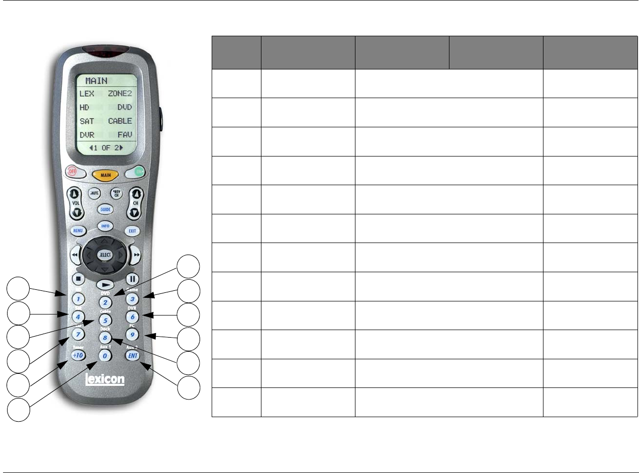
*The Menu Name is not a functional command. It is simply a label identifying which menu or sub-menu the touch screen currently
MAIN LEX PAGE1 LEX PAGE2 LEX PAGE3 LEX PAGE4
1Menu Name -
MAIN*
Menu Name - LEX Menu Name - LEX Menu Name - LEX
(iPod controls)
Menu Name - LEX
(PC controls)
2LEX
Enters the Lexicon
MV-5 menu layer
L7
Selects the Logic 7
listening mode family
EQ
Toggles the Auto EQ
parameter between
ON & OFF.
IPOD-
iPod
PC-
PC
3ZONE2
Enters the MV-5
Zone 2 menu layer
STER
Selects the Stereo
listening mode family
PRE1
Sets the MV-5 to the
Autocal Preset 1
saved values
IPOD+
iPod
PC+
PC
4TUNER
Enters the MV-5
Tuner menu layer
DOLBY
Selects the Dolby
listening mode family
PRE2
Sets the MV-5 to the
Autocal Preset 2
saved values
CLIK
iPod wheel click,
counterclockwise
PCII
PC Play/Pause
5TV
(Does not affect the
MV-5)
DTS
Selects the DTS
listening mode family
PRE3
Sets the MV-5 to the
Autocal Preset 3
saved values
CLIK
iPod wheel click,
clockwise
(unused)
6HD
(Does not affect the
MV-5)
DSP
Selects the DSP
listening mode family
TREB-
Lowers the Treble
parameter
MENU
iPod MENU button
(unused)
7DVD
Enters the Lexicon
RT-10/RT-20 menu
AUDIN
Selects either Digital
or Analog Audio.
TREB+
Raises the Treble
parameter
SEL
iPod SELECT button
(unused)
8GAME
(Does not affect the
MV-5)
TONE
Toggles the Tone
Control parameter
between ON & OFF.
BASS-
Lowers the Bass
parameter
II
iPod Play/Pause
button
(unused)
9FAV
(Does not affect the
MV-5)
ZOOM
Adjusts the Video
Zoom.
BASS+
Raises the Bass
parameter
(unused)
10 MENU PAGE - <ACTIVE PAGE> OF <TOTAL PAGES>
Touch or to scrolll between the menu pages
1
2
4
6
8
10
3
5
7
9
Note: The number call-outs on the figure above
correlate with the numbers in the adjoining table.
MV-5
2-13
displays.
*The MAIN menu level does NOT control the MV-5. The remote control touch screen heading must read “LEX”, “TUNER”, or
“ZONE 2” in order to control the MV-5 Processor.
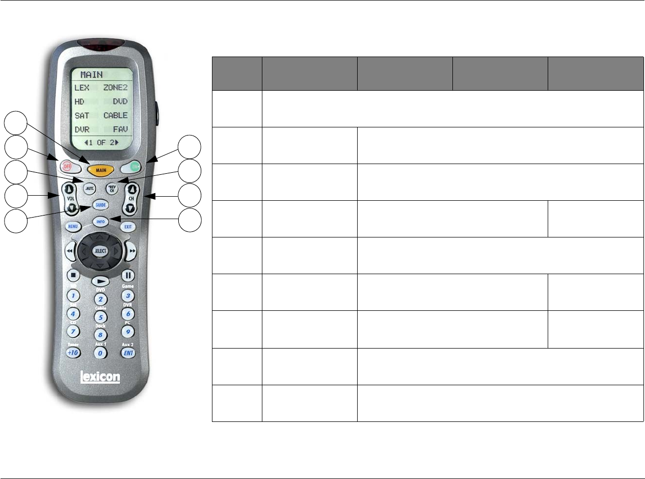
Note: The number call-outs on the figure above
correlate with the numbers in the adjoining table.
11
12
14
16
18
13
15
17
19
MAIN* LEX
PAGE1-4
TUNER
PAGE 1-3
ZONE 2
PAGE 1-3
11 MAIN*
Returns to the Main layer of the remote control
12 ON Turns on the MV-5 Processor from Standby
13 OFF Puts the MV-5 Processor into Standby
14 MUTE Mutes the Main Zone Volume Mutes the Zone 2
Volume
15 PREV CH (unused)
16 VOL or VOL Main Zone
VOL or VOL
Zone 2
VOL or VOL
17 CH or CH Main Zone
MODE or MODE
(unused)
18 GUIDE Steps through the VIDEO STATUS menu
19 INFO Steps through the AUDIO STATUS menu
Lexicon
2-14
*The MAIN menu level does NOT control the MV-5. The remote control touch screen heading must read “LEX”, “TUNER”, or
“ZONE 2” in order to control the MV-5 Processor.
Note: The number call-outs on the figure above
correlate with the numbers in the adjoining table.
20
22
24
26
21
23
25
27
28
MAIN* LEX
PAGE1-4
TUNER
PAGE 1-3
ZONE 2
PAGE 1-3
20 MENU Enters OSD menu
21 EXIT Exits OSD menu
22
REWIND
(unused)
23 SELECT Enters OSD menu,
While in OSD menu, selects menu items
24
Arrows
Used for OSD menu navigation
If not in the OSD menu structure, no function.
25
FAST FORWARD
(unused)
26
STOP
Main Zone OFF Zone 2 OFF
27 ||
PAUSE
Changes Front panel display illumination (unused)
28
PLAY
(unused)
MV-5
2-15
*The MAIN menu level does NOT control the MV-5. The remote control touch screen heading must read “LEX”, “TUNER”, or
“ZONE 2” in order to control the MV-5 Processor.
Note: The number call-outs on the figure above
correlate with the numbers in the adjoining table.
39
38
35
33
32
29
40
36
37
34
31
30
MAIN* LEX
PAGE1-4
TUNER
PAGE 1-3
ZONE 2
PAGE 1-3
29 1Main Zone
HD input
Zone 2
HD input
30 2Main Zone
DVD input
Zone 2
DVD input
31 3Main Zone
Game input
Zone 2
Game input
32 4Main Zone
Sat input
Zone 2
Sat input
33 5Main Zone
Cable input
Zone 2
Cable input
34 6Main Zone
DVR input
Zone 2
DVR input
35 7Main Zone
CD input
Zone 2
CD input
36 8Main Zone
Dock input
Zone 2
Dock input
37 9Main Zone
PC input
Zone 2
PC input
38 +10 Main Zone
Tuner input
Zone 2
Tuner input
39 0Main Zone
Aux 1 input
Zone 2
Aux 1 input
40 ENT
Enter
Main Zone
Aux 2 input
Zone 2
Aux 2 input

Lexicon
2-16

3
Setup
Setup ......................................................................................... 3-2
Display Setup ............................................................................. 3-3
Speaker/EQ Setup ...................................................................... 3-6
Rear Amp .................................................................................................. 3-7
Manual ..................................................................................................... 3-7
Semi Autocal............................................................................................. 3-7
Full Autocal ............................................................................................... 3-7
Manual Speaker Setup................................................................ 3-9
Speakers Menu........................................................................................ 3-10
Speaker Distances Menu ......................................................................... 3-11
Output Levels Menu................................................................................ 3-12
Input Setup .............................................................................. 3-14
Advanced Video ...................................................................................... 3-20
Listening Modes....................................................................... 3-23
Selecting a Listening Mode ..................................................................... 3-23
DTS + Dolby Listening Modes ................................................................. 3-23
Available Listening Modes ....................................................................... 3-24
Listening Mode Descriptions ................................................................... 3-27
5.1-channel & 7.1-channel Direct Inputs................................................. 3-28
DTS & Dolby Status Displays................................................................... 3-29
Surround Configuration ........................................................... 3-30
Dolby Configuration................................................................. 3-32
Mute Levels.............................................................................. 3-33
Power On Settings ................................................................... 3-33
Setup Lexicon
3-2
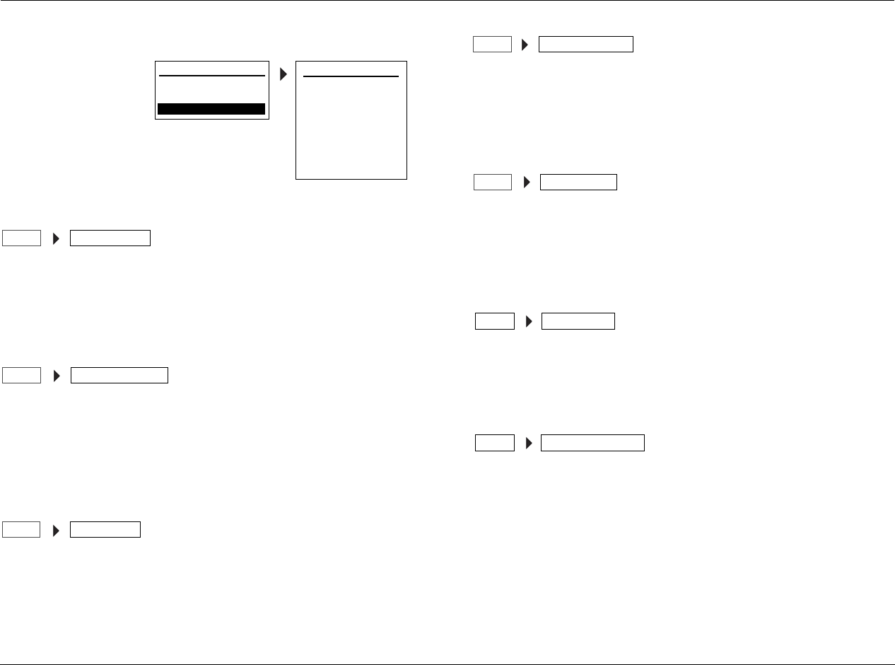
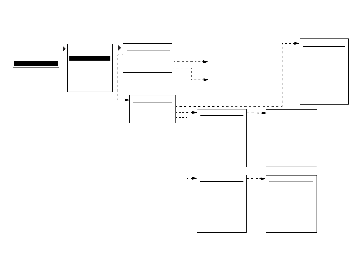
SETUP
Selecting SETUP from
the MAIN MENU
opens the SETUP
menu.
DISPLAY SETUP
Opens the DISPLAY SETUP menu, which is used to customize the
on-screen and front panel displays, identify display connection types,
and set the aspect ratio. See the “Display Setup” section found later
in this chapter for more information.
SPEAKER/EQ SETUP
Opens the SPEAKER/EQ SETUP menu, which is used to configure the
Main Zone audio output connectors for the desired speaker setup,
set speaker cross-overs, and calibrate distances and output levels. See
the “Speaker Setup” section found later in this chapter for more
information.
INPUT SETUP
Opens the INPUT SETUP menu, which is used to change input
names, assign audio and video input connectors, select preferred
listening modes and configure Main Zone and Zone 2 settings. See
the “Input Setup” section found later in this chapter for more
information.
SURROUND CONFIGURATION
Opens the SURROUND CONFIG menu, which is used to customize
the listening modes that are available for the currently selected input.
See the “Surround Configuration” section found later in this chapter
for more information.
DOLBY CONFIGURATION
Opens the DOLBY CONFIG menu, which is used to customize the Dolby
listening modes to your personal preferences. See the“Dolby
Configuration” section found later in this chapter for more
information.
MUTE LEVELS
Opens the MUTE LEVELS menu, which is used to set the mute level
controls. See the “Mute Levels” section found later in this chapter for
more information.
POWER ON SETTINGS
Opens the POWER ON SETTINGS menu, which is used to configure
the power on volume level and the Dock auto power feature. See
the “Power On Settings” section found later in this chapter for more
information.
Note: When a source is active, changing some audio or video parameters
may cause the Main Zone audio to briefly mute the incoming source. If
Zone 2 is set to DOWNMIX, the Zone 2 audio will also briefly mute.
MAIN MENU
AUDIO CONTROLS
VIDEO CONTROLS
DISPLAY SETUP
SPEAKER/EQ SETUP
INPUT SETUP
SURROUND CONFIG
DOLBY CONFIG
MUTE LEVELS
POWER ON SETTINGS
SETUP
SETUP
SETUP DISPLAY SETUP
SPEAKER/EQ SETUPSETUP
INPUT SETUPSETUP
SURROUND CONFIGSETUP
DOLBY CONFIGSETUP
MUTE LEVELSSETUP
POWER ON SETTINGS
SETUP
MV-5 Setup
3-3
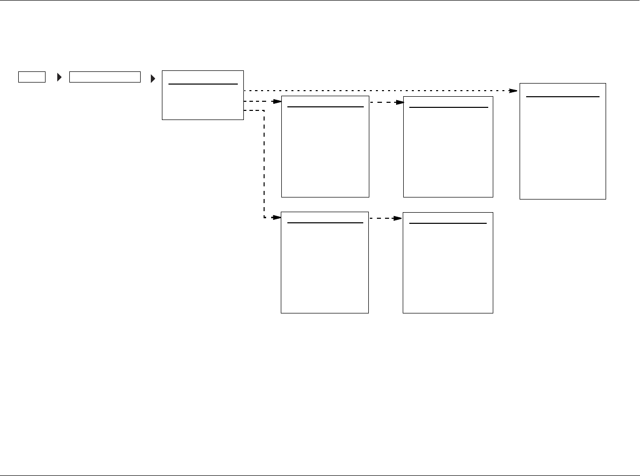
DISPLAY SETUP
Selecting the SETUP menu DISPLAY SETUP option opens the DISPLAY SETUP menu, which is used to customize the on-screen and front panel
displays, identify the preferred video aspect ratio, and setup other display-related features.
DISPLAY TYPE CRT, DLP, F-PRJ, LCD, PLASMA, R-PRJ
Selects the DISPLAY TYPE parameter, which assigns the video display
type. The different options provide slight differences to the video
enhancement level and aspect ratio for optimum performance of
different displays.
• CRT: The CRT (Cathode Ray Tube) setting is for use with
displays that use CRTs to display images. For the purposes of
this setting, it does not matter whether the display is a single
tube, direct view CRT TV or a three-tube front or rear projector.
The default aspect ratio is 4:3 but you may change that setting
via the ASPECT RATIO parameter, as described on the following
page.
• R-PRJ: The R-PRJ (Rear Project) setting is optimized for rear
projectors, regardless of the imaging technology used.
• F-PRJ: The F-PRJ (Front Project) setting is optimized for front
projectors, regardless of the imaging technology used.
• PLASMA: The Plasma setting is optimized for plasma displays,
regardless of whether they are true high-definition or ED
displays that are HD-compatible.
• DLP: The DLP (Digital Light Processing™) setting is for use with
projectors that use light engines with Texas Instruments’ DLP®
technology. For the purposes of this settings, it does not matter
whether the display uses one or three chips, or whether the
display is front or rear projection.
• LCD: The LCD (Liquid Crystal Display) setting is optimized for
use with LCD displays. For the purposes of this setting, it does
not matter whether the display is a direct-view LCD flat panel,
or front/rear projector.
ON-SCREEN DISPLAY
2-LINE OSD: 3s
MENU TIME OUT: 30s
FRONT PANEL DISPLAY
BRIGHTNESS: FULL
TIME OUT: NONE
DISPLAY SETUP
DISPLAY TYPE: PLASMA
ASPECT RATIO: 16:9
CONNECTION: HDMI/DVI
HDMI AUDIO OUT: NO
ON-SCREEN DISPLAY
FRONT PANEL DISPLAY
MAIN MENU
AUDIO CONTROLS
VIDEO CONTROLS
DISPLAY SETUP
SPEAKER/EQ SETUP
INPUT SETUP
SURROUND CONFIG
DOLBY CONFIG
MUTE LEVELS
POWER ON SETTINGS
SETUP
SETUP
DISPLAY SETUPSETUP DISPLAY TYPE

Setup Lexicon
3-4
ASPECT RATIO 4:3, 16:9
Selects the ASPECT RATIO parameter, which assigns the appropriate
aspect ratio for the display device. The 4:3 aspect ratio is almost
square and most commonly used for television. The 16:9 aspect
ratio, also referred to as Widescreen, is almost twice as wide as it is
high.
Note: This parameter does not affect the OSD menus, which will always
be output to the monitor in 4:3 aspect ratio.
CONNECTION ANALOG, HDMI/DVI
Selects the CONNECTION parameter, which identifies the active
video output connectors on the MV-5 rear panel. The following list of
conditions identify the behavior of this parameter.
• If ANALOG is selected, only the analog video connectors are
available and will output the video signal.
• If HDMI/DVI is selected, both the analog and HDMI video
connectors are available and will output the video signal.
• If the video input is set to HDMI and the CONNECTION
parameter is set to ANALOG, then no video is output.
• If the HDMI video input is copy-protected (HDCP), no video is
output on the analog output connectors. This is a requirement
of HDCP and not a limitation of the MV-5 Processor
HDMI AUDIO OUT YES, NO
Selects the HDMI AUDIO OUT parameter, which identifies if audio is
sent on the HDMI output. If the HDMI Audio Out parameter is set to
YES, then a two-channel downmix of the source audio is sent over
the HDMI connection at the maximum bit rate of the display’s audio
system. This audio stream is in addition to the normal audio outputs.
If the parameter is set to NO, this audio is not sent.
2-LINE OSD OFF, 3, 4, 5, 6 SECONDS
Selects the 2-LINE OSD parameter from the On-Screen Display (OSD)
menu. The 2-Line OSD parameter identifies the length of time that
the 2-line OSD is displayed. The 2-Line OSD can be displayed from
three to six seconds in one-second increments. If OFF is selected,
then the 2-line OSD is not displayed.
MENU TIME OUT NONE, 30, 40, 50, 60 SECONDS
Selects the MENU TIME OUT parameter from the On-Screen Display
(OSD) menu. This parameter identifies the length of time before the
OSD menu times out. The parameter can be set from 30 to 60
seconds in ten-second increments. If NONE is selected, then the OSD
is always on when the MV-5 is on.
CAUTION!
The NONE selection should only be used with caution. If
the system includes a plasma screen, or other monitor
types sensitive to image burn-in, and the OSD Menu Time
Out parameter is set to NONE, the OSD menu image can be
burned into the plasma screen.
DISPLAY SETUPSETUP ASPECT RATIO
DISPLAY SETUP
SETUP CONNECTION
DISPLAY SETUPSETUP HDMI AUDIO OUT
DISPLAY SETUPSETUP ON-SCREEN DISPLAY 2-LINE OSD
DISPLAY SETUPSETUP ON-SCREEN DISPLAY MENU TIME OUT
MV-5 Setup
3-5
BRIGHTNESS FULL, HALF, OFF
Selects the BRIGHTNESS parameter from the Front Panel Display
menu, which selects the brightness of the 2-line front panel display.
The parameter can be set to FULL, HALF, or OFF. If set to OFF, then
the front panel display is off.
On the remote control, this parameter is controlled by the || (Pause)
button while in the touch screen LEX or TUNER menus.
TIME OUT NONE, 1 TO 10 SECONDS
Selects the TIME OUT parameter from the Front Panel Display menu.
This parameter identifies the length of time before the front panel
2-line display times out. The parameter can be set from 1 to 10
seconds in one-second increments. If NONE is selected, then the
2-line front panel display is always on when the MV-5 is on.
DISPLAY SETUP
SETUP FRONT PANEL DISPLAY BRIGHTNESS
DISPLAY SETUP
SETUP FRONT PANEL DISPLAY TIME OUT
Setup Lexicon
3-6
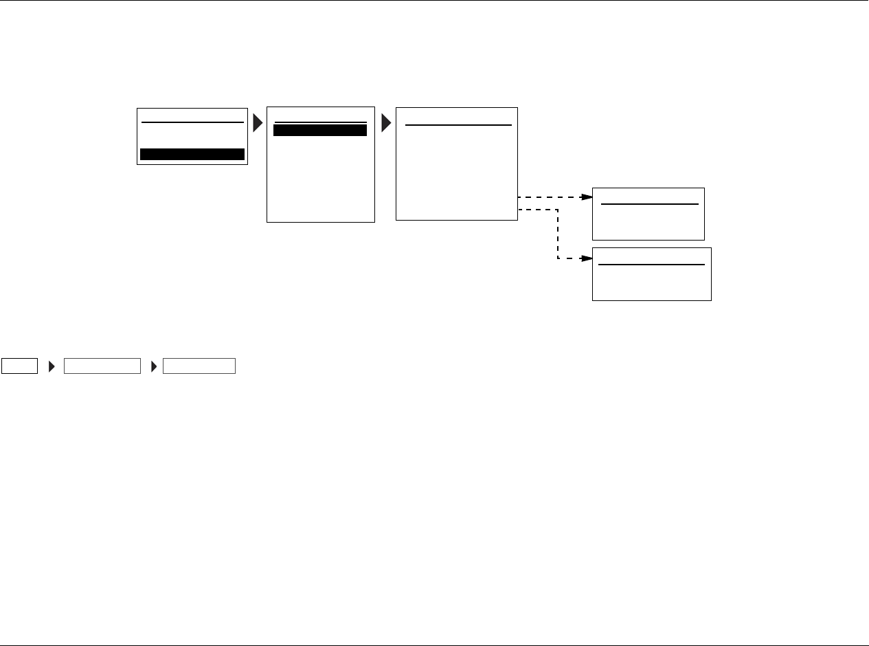
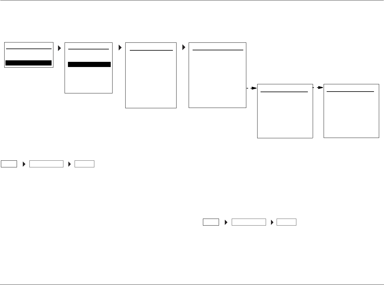
SPEAKER/EQ SETUP
Select the SPEAKER/EQ SETUP menu to configure the Main Zone audio output connectors for the desired speaker setup. The Main Zone includes eight
audio output connectors labeled Front L/R, Center, Subwoofer, Side L/R and Rear L/R.
MANUAL
SPEAKERS
SPEAKER DISTANCES
OUTPUT LEVELS
SPEAKERS
AUTO SETTINGS: OFF
FRONT L/R: 80Hz
CENTER: 80Hz
SIDE L/R: 80Hz
REAR/Z2 L/R: 80Hz
SUB/LFE LPF: 80Hz
SUBWOOFERS: 1
SUB HPF: 20Hz
SUB MODE: NORMAL
PERFORMS FULL AUTOMATIC
CALIBRATION
PERFORMS SEMI-AUTOMATIC
CALIBRATION
MAIN MENU
AUDIO CONTROLS
VIDEO CONTROLS
DISPLAY SETUP
SPEAKER/EQ SETUP
INPUT SETUP
SURROUND CONFIG
DOLBY CONFIG
MUTE LEVELS
POWER ON SETTINGS
SETUP
SETUP SPEAKER/EQ SETUP
MANUAL
SEMI AUTOCAL
FULL AUTOCAL
SPEAKER DISTANCES 1
AUTO SETTINGS: OFF
UNITS: FEET
FRONT LEFT: 0.0 ft
CENTER: 0.0 ft
FRONT RIGHT: 0.0 ft
SIDE RIGHT: 0.0 ft
REAR RIGHT: 0.0 ft
REAR LEFT: 0.0 ft
SPEAKER DISTANCES 2
SIDE LEFT: 0.0ft
SUBWOOFERS: 0.0 ft
OUTPUT LEVELS 1
AUTO SETTINGS: OFF
INPUT: ALL
TEST TONE: OFF
FRONT LEFT: 0dB
CENTER: 0dB
FRONT RIGHT: 0dB
SIDE RIGHT: 0dB
REAR RIGHT: 0dB
OUTPUT LEVELS 2
RIGHT LEFT: 0dB
SIDE LEFT: 0dB
SUBWOOFER1: 0dB
SUBWOOFER2: 0dB

MV-5 Setup
3-7
MANUAL
Opens the MANUAL speaker setup menu, which allows the manual
selection of the speaker distances, cross-over points, and output
levels. See the next section, “Manual Speaker Set-Up”, for more
details.
SEMI AUTOCAL
Selects the SEMI AUTOCAL procedure, which automatically sets the
speaker distances and output levels, as well as performing system
equalization adjustments. The cross-over points for each speaker
must be manually set before this procedure can be run. See the next
section, “Manual Speaker Set-Up”, for more information on how to
set the cross-over points.
Performing the Semi Autocal Procedure:
In order to perform this test, the following initial setup is required:
• All of the speakers are connected to the MV-5 and positioned in
the listening space.
• The cross-over points for each speaker are set through the
MANUAL setup menu.
Note: See the following section, “Manual Speaker Setup”, for
information on how to manually set the cross-over points.
• A monitor is connected to the MV-5 for viewing the OSD
during the procedure.
• The microphone, included with the MV-5, must be connected
to the rear panel Microphone connector and positioned in the
primary listening position.
Note: For best results, install the microphone onto the accompanying
rod by threading the two parts together and hold or place in the
primary listening position. Use a microphone stand or tripod if
necessary.
The Semi Autocal procedure is performed in the same manner as the
Full Autocal procedure. Refer to the “Performing the Full Autocal
Procedure” for more details.
CAUTION!
DO NOT place the microphone too close to the speakers
during the autocal procedure. If the microphone is within
one foot of the speaker, the test tones that are output
during the autocal procedure could cause a feedback loop
which may damage the speaker. Lexicon assumes no
responsibility for speaker damage.
FULL AUTOCAL
Selects the FULL AUTOCAL procedure, which automatically sets the
speaker distances, cross-over points, and output levels, as well as
performing system equalization adjustments.
Note: The Full or Semi Autocal settings that are saved to the Preset
locations include the system equalization adjustment values. However,
even if the Auto EQ setting is active, the autocal settings for the system EQ
do NOT apply to certain high bit-rate incoming data streams, such as 176
kHz and 192 kHz PCM.
Performing the Full Autocal Procedure:
In order to perform this test, the following initial setup is required:
• All of the speakers are connected to the MV-5 and positioned in
the listening space.
• A monitor is connected to the MV-5 for viewing the OSD
during the procedure.
• The microphone, included with the MV-5, must be connected
to the rear panel Microphone connector and positioned in the
primary listening position.

Setup Lexicon
3-8
Note: For best results, install the microphone onto the accompanying rod
by threading the two parts together and hold or place in the primary
listening position. Use a microphone stand or tripod if necessary.
The Full Autocal procedure is comprised of three parts, the Far Field
Test, the Near Field Test, and the Subwoofer Test. Each part provides
on-screen directions at the start of the test, for volume level and
microphone positioning, and each test sends test tones to the
speakers.
Note: Before activating the calibration, ensure that the MV-5 is NOT
muted. If Mute is active, then the test tone calibrations will not be
accurate.
For the Far Field test, the test tones sent to each speaker follow a
specific order. The order of testing is Front Left, Front Right, Center,
Side Left, Side Right, Rear Left, and Rear Right.
Note: The test tones may be loud. Be prepared before starting the Full or
Semi Autocal procedures.
The Far Field test sets the speaker distances, cross-over points, and
output levels. The microphone is stationed in the center of the
preferred listening area and a test tone is sent to each speaker.
Note: If the Far Field test is skipped, the Near Field test must also be
skipped.
The Near Field test adjusts the MV-5, performing system equalization
to compensate for speaker performance and placement. The
procedure seeks to give the system a consistent tonal balance
between the front left, front right, center, side left, side right, rear left,
and rear right speakers, if applicable. The test calibrates each speaker
separately, and the user individually selects each speaker to calibrate.
The microphone should be held within two feet of the speaker front
as a test tone is sent to the speaker.
The Subwoofer test is done in two parts. The user is instructed to
hold the microphone to the left of the primary listening position and
then to the right of the primary listening position. Two test tones are
sent out to all connected subwoofers during each of the two test
phases. Two tones are sent to ensure that subwoofers with auto
power settings are active during the procedure.
Note: If there are no subwoofers in the system, then this test will not pass
and must be skipped.
For optimum results, all noise generators in the room should be
removed before performing the full or semi autocal procedure.
However, air conditioners and similar steady-state background noise
should have minimum impact on the test.
When the procedure is complete, the user will be prompted to save
the settings. These settings can be saved in one of three Preset
locations. See Section 4: Audio & Video Controls for more information
on the Preset locations.
CAUTION!
DO NOT place the microphone too close to the speakers
during the autocal procedure. If the microphone is within
one foot of the speaker, the test tones that are output
during the autocal procedure could cause a feedback loop
which may damage the speaker. Lexicon assumes no
responsibility for speaker damage.
MV-5 Setup
3-9
MANUAL SPEAKER SETUP
Selecting the SETUP menu SPEAKER/EQ SETUP menu MANUAL option opens the MANUAL menu, which is used to manually set the speaker
distances, cross-over points, and output levels.
AUTO SETTINGS OFF, ON
Loads the values from the active preset into the speaker cross-over
points, distances, or output level parameters. The Speakers
(cross-over points), Speaker Distances, and Output Levels menus all
have an Auto Settings parameter. All three are the same parameter,
but each affects the individual sub-menus separately and
independently of each other.
If the Auto Settings parameter is set to ON, the parameters in that
menu cannot be manually changed until the Auto Settings
parameter is set to OFF.
Note: Any manual settings will be lost if the active preset settings are
loaded; if Auto Settings is set to ON in the Speakers, Speaker Distances, or
Output Levels menus, then previous parameter values will be overwritten.
MANUAL
SPEAKERS
SPEAKER DISTANCES
OUTPUT LEVELS
SPEAKERS
AUTO SETTINGS: OFF
FRONT L/R: 80Hz
CENTER: 80Hz
SIDE L/R: 80Hz
REAR/Z2 L/R: 80Hz
SUB/LFE LPF: 80Hz
SUBWOOFERS: 1
SUB HPF: 20Hz
SUB MODE: NORMAL
SPEAKER DISTANCES 1
AUTO SETTINGS: OFF
UNITS: FEET
FRONT LEFT: 0.0 ft
CENTER: 0.0 ft
FRONT RIGHT: 0.0 ft
SIDE RIGHT: 0.0 ft
REAR RIGHT: 0.0 ft
REAR LEFT: 0.0 ft
SPEAKER DISTANCES 2
SIDE LEFT: 0.0ft
SUBWOOFERS: 0.0 ft
OUTPUT LEVELS 1
AUTO SETTINGS: OFF
INPUT: ALL
TEST TONE: AUTO
FRONT LEFT: 0dB
CENTER: 0dB
FRONT RIGHT: 0dB
SIDE RIGHT: 0dB
REAR RIGHT: 0dB
OUTPUT LEVELS 2
RIGHT LEFT: 0dB
SIDE LEFT: 0dB
SUBWOOFER1: 0dB
SUBWOOFER2: 0dB
SPEAKER/EQ SETUPSETUP

Setup Lexicon
3-10
SPEAKERS MENU
Selecting the MANUAL SETUP menu SPEAKERS option opens the SPEAKERS menu, which assigns independent crossover points for each Main Zone
audio output connector. Front cross-over selections affect the Sub Mode parameter options.
Manual Speaker Setup Considerations:
• Select the crossover point closest to the -3dB low frequency
rating of the associated speakers. For example, set the FRONT
L/R parameter to the crossover point closest to the -3dB
low-frequency rating of the front speakers.
• Select the subwoofer crossover point equal to the lowest
crossover point of any of the other speakers.
Manual Subwoofer Speaker Setup Considerations:
All low frequencies below the speaker’s cross-over point are
redirected from the speaker to the subwoofer(s). If the cross-over
point is FULL, low-frequency signals, excluding LFE information, are
not redirected to the subwoofer.
Low frequencies between the Subwoofer and Front L/R speaker
channels can be duplicated, commonly called “Duplicate Bass”.
However, making this selection can result in excessive bass. Refer to
the “Sub Mode” description found later in this chapter for more
information.
Note: The Semi Autocal and Full Autocal procedures leave the Subwoofer
distance value at a default of 0.0 feet. Refer to the “Speaker Distances”
section found later in this chapter to manually set the correct Speaker
Distance for the subwoofers.
FRONT L/R FULL, 40 to 120HZ
Allows the manual selection of a crossover point for the Main Zone
audio output connectors labeled Front L/R. Available selections
include FULL, 120 Hz, 100 Hz, and 80 Hz to 40 Hz in 10 Hz
increments.
Select FULL to send a full-range signal to the front speakers.
Otherwise, select the cross-over point closest to the -3dB
low-frequency rating of the front speakers.
CENTER FULL, 40 to 120HZ, NONE
Allows the manual selection of a crossover point for the Main Zone
audio output connector labeled Center. Available selections include
NONE, FULL, 120 Hz, 100 Hz, and 80 Hz to 40 Hz in 10 Hz
increments.
• Select FULL to send a full-range signal to the center speaker.
Otherwise, select the crossover point closest to the -3dB
low-frequency rating of the center speaker.
• When the speaker setup does not include a center speaker, select
NONE to redirect center channel signals to the Front L/R output
connectors.
SIDE L/R FULL, 40 to 120Hz, NONE
Allows the manual selection of a crossover point for the Main Zone
audio output connectors labeled Side L/R. Available selections
include NONE, FULL, 120 Hz, 100 Hz, and 80 Hz to 40 Hz in 10 Hz
increments.
• Select FULL to send a full-range signal to the Side L/R speakers.
Otherwise, select the crossover point closest to the -3dB
low-frequency rating of the Side L/R speakers.
• When the speaker setup does not include side speakers, select
NONE to redirect side channel signals to the Front L/R output
connectors. If the Rear/Z2 L/R parameter is also set to NONE,
the MV-5 will redirect surround channel signals to the Front L/R
output connectors.

MV-5 Setup
3-11
REAR/Z2 L/R FULL, 40 to 120Hz, NONE
Allows the manual selection of a crossover point for the Main Zone
audio output connectors labeled REAR/Z2 L/R. Available selections
include NONE, FULL, 120 Hz, 100 Hz, and 80 Hz to 40 Hz in 10 Hz
increments.
• Select FULL to send a full-range signal to the Rear/Zone2 L/R
speakers. Otherwise, select the crossover point closest to the
-3dB low- frequency rating of the Rear/Zone2 L/R speakers.
• When the speaker setup does not include rear speakers, select
NONE to redirect rear channel signals to the Side L/R output
connectors. If the Side L/R parameter is also set to NONE, the
MV-5 will redirect surround channel signals to the Front L/R
output connectors.
Note: When the Rear/Z2 L/R parameter is set to NONE, Dolby Digital
PLIIx modes and DTS(-ES) decoding are not available.
SUB/LFE LPF (LOW-PASS FILTER) 40 to 120 Hz
Identifies the cross-over frequency setting below which sounds that
may be available from a special LFE track are sent to the subwoofer.
Available selections are 120 Hz, 100 Hz, and 80 Hz to 40 Hz in 10 Hz
increments.
SUBWOOFERS 0, 1, 2
Selects the number of subwoofers in the system. Available selections
are 0, 1, or 2. The 0 selection is only available if the Front Left &
Right speakers are set to FULL.
SUB HPF (HIGH-PASS FILTER) 15, 20, 30, 38 Hz
Identifies the cross-over frequency setting above which sounds are
sent to the subwoofer. Available selections include 15, 20, 30, and 38
Hz. As a general rule of thumb, the larger the subwoofer driver, the
lower the frequency should be of the Sub HPF parameter.
SUB MODE NORMAL, LFE+FL/FR, LFE ONLY
Selects additional options that are available to further control bass
redirection. Available settings are NORMAL, LFE+FL/FR and LFE
ONLY.
NORMAL is the default setting when Front L/R crossovers are set to
any value other than FULL, and it is not user adjustable. In this mode,
all frequencies below the crossover point of any main speakers (Front,
Center, Side, or Rear) are sent to the subwoofer. In addition, if the
incoming audio stream contains an LFE (.1) channel, all frequencies
in that channel which are below the SUB/LFE LPF crossover point are
also sent to the subwoofer(s).
When the Front L/R crossover is set to FULL, the user has the choice
of LFE+FL/FR or LFE ONLY.
The default setting, LFE+FL/FR, steers all Front L/R sounds below a
fixed crossover point of 80Hz to BOTH the subwoofer(s) and the
front left/right speakers. In addition, it redirects all frequencies below
the crossover points of the Center, Side, and Rear speakers to the
subwoofer(s). Finally, if the incoming audio stream contains an LFE
(.1) channel, all frequencies in that channel which are below the
SUB/LFE LPF crossover point are also sent to the subwoofer(s).
The LFE ONLY setting does not send any sound to the subwoofer(s)
other than the LFE (.1) channel, if available.
SPEAKER DISTANCES MENU
Selecting the MANUAL SETUP menu SPEAKER DISTANCES option
opens the SPEAKER DISTANCES menu, which allows the user to
manually set the distances for each speaker. The adjustable range is
0.0 ft (0.0 m) to 30.0 ft (9.00 m) at 0.2 ft (0.06 m) increments.

Setup Lexicon
3-12
The distances for each speaker - Front Left, Center, Front Right, Side
Right, Rear Right, Rear Left, Side Left, and Subwoofers - can be set
individually.
Note: When the speaker distance for the Front Left speaker is adjusted
above 20.0 feet from the shortest speaker distance, all speaker distances
will move in conjunction from the 20.2-feet parameter point. When the
Front Left speaker is adjusted to 20.2 feet, all other speaker distances that
are set to 0 feet will now move to 0.2 feet. If the Front Left speaker
distance is increased to 22 feet, all other speaker distances will move to 2
feet (unless they are set to a higher value). If the Front Left speaker
distance is then decreased, all other speaker distances will not change.
UNITS FEET, METERS
Identifies the units of measure of the speaker distances. Feet and
Meters are the available selections.
OUTPUT LEVELS MENU
Selecting the MANUAL SETUP menu OUTPUT LEVELS option opens
the OUTPUT LEVELS menu, which allows the user to manually set the
output levels for each speaker. The output levels can be set
independently for each input. The adjustable range is -15 dB to +5 dB
in 1 dB increments.
The output levels for each speaker - Front Left, Center, Front Right,
Side Right, Rear Right, Rear Left, Side Left, Subwoofer1, and
Subwoofer2 - can be set individually.
Note: The speaker output level settings may affect the maximum volume
level of the MV-5 Processor. The maximum volume level is +10 dB minus
the maximum output level setting of any speaker. Thus, if your Front L/R
output levels are set to +3.0 dB, then the maxium allowable volume level
is +10 dB minus +3 dB, or +7.0 dB.
INPUT
Identifies to which input the currently displayed output levels will be
applied. The Input selection toggles between the currently selected
front panel input and ALL. If the front panel input is selected, then
only that input’s output levels are adjusted.
Note: To set a specific input’s output levels, the input front panel button
must be selected before the Input selection in the Output Levels menu is
available for that specific input.
The ALL selection functions as a virtual input – it holds values that can
be assigned to all inputs. Each input can override the ALL value with
its own custom settings. To assign the ALL input, it must be selected
individually for each front panel input selection.
Note: If the input is set to ALL and the auto settings are turned to ON,
then ALL takes the preset values for its settings. The Auto Settings, if set to
ON, apply to whatever INPUT is currenly selected.
TEST TONE OFF, AUTO, MANUAL
Provides a pink noise signal to each speaker through either the AUTO
or MANUAL setting. Automatic sends rotating pink noise to each
speaker, in the order listed in the menu. If set to AUTO, the test tone
moves in a clockwise order around the speakers, starting from the
front left. Manual sends the pink noise signal only to the speaker
selected by the user. The OFF selection turns off the noise signal
generator. Any active input source is muted while the Test Tone
parameter is active and until the Test Tone parameter is set to OFF.
The available test tones are dependent upon the current listening
mode. For example, if a 5.1 channel listening mode is active, then
the rear speakers are not accessible to the Test Tone parameter.

MV-5 Setup
3-13
Note: Before activating the test tones, ensure that the MV-5 is NOT
muted. If Mute is active, then the test tone calibrations will not be
accurate.
Setup Lexicon
3-14
INPUT SETUP
Selecting the SETUP menu INPUT SETUP option opens the INPUT SETUP menu, a two-screen menu which sets up the input type and name, the
digital and analog inputs for both audio and video, the listening mode, and other advanced input settings.
INPUT
Selects between the twelve different inputs available. The input
selected in this parameter identifies the input that is currently being
setup or modified. Inputs can be scrolled through and modified
without leaving the input setup menu. However, most input setup
changes do not take affect until after the OSD menu is exited.
Note: Selecting a different input in the input setup menu will also change
the front panel input selection to match. For example, if the Tuner is
selected on the front panel and you change the Input parameter to HD,
the front panel HD input is also selected.
Most of the inputs are interchangeable, with the exception of the
Dock, PC, and Tuner inputs. These three inputs are “hard-wired” and
do not allow for user selection of the Audio In parameters. For more
information on these three inputs, refer to Section 5: Tuner, PC, and
Dock Controls.
Note: When a source is active, changing some audio or video parameters
may cause the Main Zone audio to briefly mute the incoming source. If
Zone 2 is set to DOWNMIX, the Zone 2 audio will also briefly mute.
NAME
Allows the user to customize the name of the selected input. Custom
input names can include up to eight characters.
Note: A custom name cannot be assigned to the Tuner input.
INPUT TYPE: VCR
SHARPNESS: 32
NOISE REDUCTION: ON
X-COLOR SUPPRESS: ON
DCDi INTERPOL: ON
FILM DETECTION: ON
FILM EDIT DETECT: ON
ADVANCED VIDEO 1
INPUT SETUP 1
INPUT: HD
NAME: ________
DIG AUDIO: HDMI 1
ANLG AUDIO: NONE
DIG/ANLG AUTO: ON
A/D SAMPLE RATE: 48kHz
MODE FAMILY: STEREO
MODE: 2-CHANNEL
INPUT SETUP 2
DEFAULT SUR: USE LAST
VIDEO IN: HDMI 1
V-PROCESS: FAROUDJA
VIDEO OUT: AUTO
ADVANCED VIDEO
A/V SYNC DELAY: 0 ms
TRIGGER 2: ON
ZONE-2 OUT: ANALOG
MAIN MENU
AUDIO CONTROLS
VIDEO CONTROLS
DISPLAY SETUP
SPEAKER/EQ SETUP
INPUT SETUP
SURROUND CONFIG
DOLBY CONFIG
MUTE LEVELS
POWER ON SETTINGS
SETUP
SETUP
FLESHTONE NR: ON
COMPNT ENHANCE: ON
BRIGHTNESS: 100
CONTRAST: 100
COLOR: 100
TEST PAT: OFF
ADVANCED VIDEO 2
INPUT SETUPSETUP INPUT
INPUT SETUPSETUP NAME
MV-5 Setup
3-15
To Customize the Name of the Selected Input:
1. Select the input and enter the Input Setup menu.
2. Select the Name parameter. Note that a blinking dot or square
appears in the first letter position.
3. Using the and arrows, scroll through the letter list until you
find the first desired letter.
The letter list is arranged with Uppercase letters > lowercase
letters > numbers > symbols. The letters are listed in alphabetical
order and the numbers in numerical order. All standard ASCII
characters are included.
4. Press the SELECT button or arrow to save the first letter and
move to the next letter. A blinking dot appears in the second letter
position.
5. Repeat Steps 2 through 4 until the complete name is entered.
Note: The arrow saves the custom name. The arrow allows you to
move forward, one space per one button press. To add a space to your
custom name, press the SELECT button or arrow without choosing a
letter.
Use the same procedure to edit a previously saved name.
VIDEO IN
Selects the VIDEO IN parameter, which assigns one of the rear panel
video input connectors to the current input. Available selections
include NONE, HDMI 1-2, Component 1-3, S-Video 1-4, and
Composite 1-4.
The HDMI Audio & Video inputs, HDMI 1 and HDMI 2, are mutually
exclusive inputs - only one input is available at a time for each input
location. For example, while setting up the DVD input, if HDMI 2 is
selected for the Video Input, then HDMI 1 is not a selectable option
for the Digital Audio Input.
V-PROCESS FAROUDJA, CONV ONLY, BYPASS
Selects the V-PROCESS parameter, which identifies the type of video
processing or conversion, if any, which is applied to the selected
input source. Explanations of the available selections are listed below.
Faroudja - The video signals can be handled in several different ways,
depending upon the input source.
• A standard-definition (480i or 576i) analog signal
(composite, S-video, or component) will be digitized and
sent to the Faroudja video processor for enhancement.
The signal will be available as both an analog component
and an HDMI signal.
• An analog component high-definition signal will be
digitized and sent to the Faroudja video processor for
enhancement. The signal will be available as both an
analog component and an HDMI signal, but not at the
analog composite or S-video monitor outputs.
• Any HDMI signal other than 1080i will be sent to the
Faroudja video processor for enhancement and it will be
available as an output at both the HDMI and analog
component outputs. Program material that carries HDCP
(High-Bandwidth Digital Content Protection) encoding
will only be available through the HDMI output.
• HDMI signals in 1080i resolution will be sent directly to
the HDMI and analog component outputs without
processing. Program material that carries HDCP
encoding will only be available through the HDMI
output.
The Faroudja selection delivers the best image quality when a digital
video display is in use but it requires the use of a video display
capable of accepting high-resolution (480p and above) signals
through either an HDMI or component video connection.
INPUT SETUPSETUP VIDEO IN
INPUT SETUPSETUP V-PROCESS

Setup Lexicon
3-16
Conv Only - Does not apply any video enhancement or processing
to the incoming video signal, but will output the signal in one of the
following ways, depending on the input source.
• A standard-definition (480i or 576i) analog signal
(composite, S-video, or component) will be converted
so that it is available as an HDMI signal at its input
resolution, as well as at the standard S-video,
composite, or component analog video outputs.
• An analog component high-definition signal will be
digitized and output at its input resolution through the
HDMI outputs and as an analog component signal, but
not through the analog composite or S-video monitor
outputs.
• HDMI signals, regardless of their resolution, will be
output through both the HDMI and analog component
outputs. Program material that carries HDCP encoding
will only be available through the HDMI output.
Bypass – Does not apply any video enhancement or processing to
the incoming video signal, but will output the signal in one of the
following ways, depending on the input source.
• Analog signals (composite, S-video, or component) will
output only in the resolution and format that matches
the input.
• HDMI input signals, regardless of their resolution, will
be output through the HDMI and analog component
outputs. Program material that carries HDCP encoding
will only be available through the HDMI output.
Note: If you are not getting the expected resolution options for your video
monitor, it may be caused by an incompability between the input setup
selections and the incoming signal. Refer to the Video Resolutions Table in
Section 6: Troubleshooting and Maintenance for more detailed
information.
VIDEO OUT
VIDEO OUT is a multi-purpose parameter; the function of the
parameter depends upon the input source and the setting of the
V-PROCESS parameter.
When the V-PROCESS parameter is set to BYPASS or CONV ONLY, the
VIDEO OUT parameter is a non-adjustable status display of the video
resolution of the output signal, as determined by the input.
When the Faroudja video processing is selected for the V-PROCESS
parameter and the output is a digital format, VIDEO OUT becomes
an active user-selectable parameter which identifies the video output
resolution. Available selections are AUTO, 1080i, 720p, and 480p.
The AUTO option, which is only applicable for HDMI configurations,
automatically selects the highest output resolution supported by an
HDMI-equipped monitor.
DIG AUDIO
Selects the DIG AUDIO parameter, which assigns one of the rear
panel digital audio input connectors to the current input. Available
selections include None, Optical 1-4, Coaxial 1-4, and HDMI 1-2.
The HDMI Audio & Video inputs, HDMI 1 and HDMI 2, are mutually
exclusive inputs - only one input is available at a time for each input
location. For example, while setting up the DVD input, if HDMI 2 is
selected for the Video Input, then HDMI 1 is not a selectable option
for the Digital Audio Input.
Note: Digital audio is not selectable for the Tuner, PC, and Dock inputs.
Refer to Section 5: Tuner, PC, and Dock Controls for more information.
INPUT SETUPSETUP VIDEO OUT
INPUT SETUPSETUP DIG AUDIO
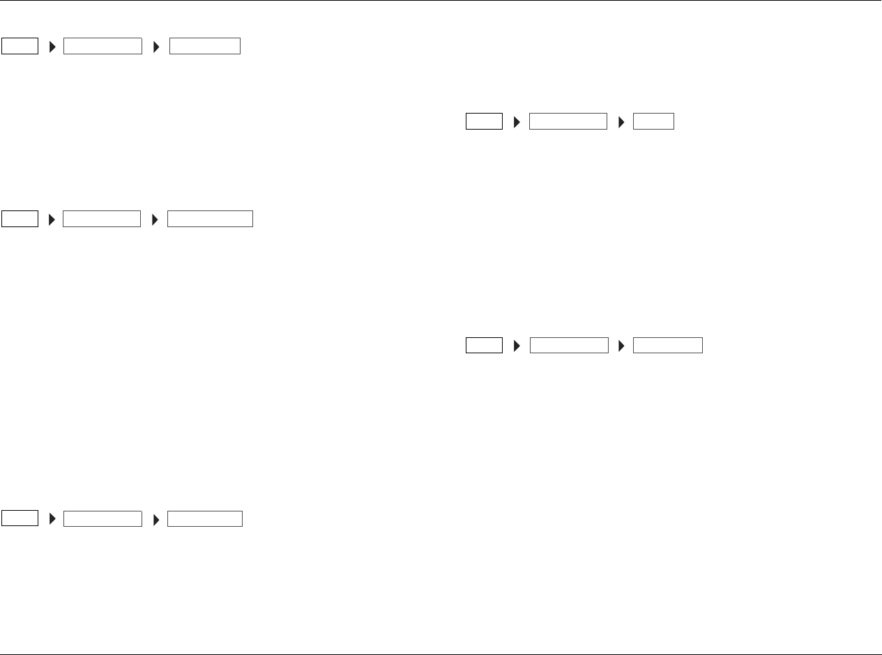
MV-5 Setup
3-17
ANLG AUDIO
Selects the ANLG AUDIO parameter, which assigns one of the rear
panel analog audio input connectors to the current input. Available
selections include None, Analog 1-6, 7.1 Analog, and 5.1 Analog.
Note: Analog audio is not selectable for the Tuner, Dock, and PC inputs.
Refer to Section 5: Tuner, PC, and Dock Controls for more information.
DIG/ANLG AUTO OFF, ON
Selects the DIG/ANLG AUTO parameter, which identifies if the MV-5
should switch to an analog signal source for an input where the
digital input source has been interupted. This feature is particularly
useful with certain cable set-top boxes where the signal is normally
digital but occasionally changes to analog.
The parameter, when set to ON, identifies if there is both a digital
and analog signal present to the input. If this condition is true, then
the MV-5 prioritizes the digital signal over the analog signal. When
the digital signal is interupted, then it switches to the analog signal.
Note: Digital/analog auto switching is not selectable for the Tuner, Dock,
and PC inputs. Refer to Section 5: Tuner, PC, and Dock Controls for more
information.
MODE FAMILY LOGIC 7, DOLBY, DTS, DSP, STEREO
Identifies the surround mode family that is initially applied to the
incoming audio streams for the currently selected input. Other
surround mode families may still be applied. For more information,
refer to the “Listening Modes” section found later in this chapter.
Note: The Mode Family and Mode parameters are connected. The modes
are driven by the mode family selection as well as by the incoming audio
source. The current running data stream dictates what mode family
options are available for selection.
MODE
Identifies the listening mode that is initially applied to the incoming
audio streams for the currently selected mode family. Other listening
modes may still be applied. For more information, refer to the
“Listening Modes” section found later in this chapter.
Note: The Mode Family and Mode parameters are connected. The modes
are driven by the mode family selection as well as by the incoming audio
source. The current running data stream dictates what mode family
options are available for selection.
DEFAULT SUR STANDARD, USE LAST
Identifies the default surround mode that is activated when a digital
source is selected. The STANDARD parameter activates the specific
surround mode encoded by the source input. The USE LAST selection
allows the MV-5 software to “remember” the last used listening
mode for any given input source. Once selected, that mode will
always be active on the corresponding input until another listening
mode is selected. This parameter affects all inputs.
Note: If the LOGIC 7 DEFAULT parameter in the SURROUND CONFIG
menu is set to ON, the USE LAST selection is defeated and the listening
mode will always switch to a LOGIC 7 mode. For normal functionality
with the USE LAST selection, make sure that the LOGIC 7 DEFAULT
parameter is set to OFF.
INPUT SETUPSETUP ANLG AUDIO
INPUT SETUPSETUP DIG/ANLG AUTO
INPUT SETUP
SETUP MODE FAMILY
INPUT SETUPSETUP MODE
INPUT SETUPSETUP DEFAULT SUR
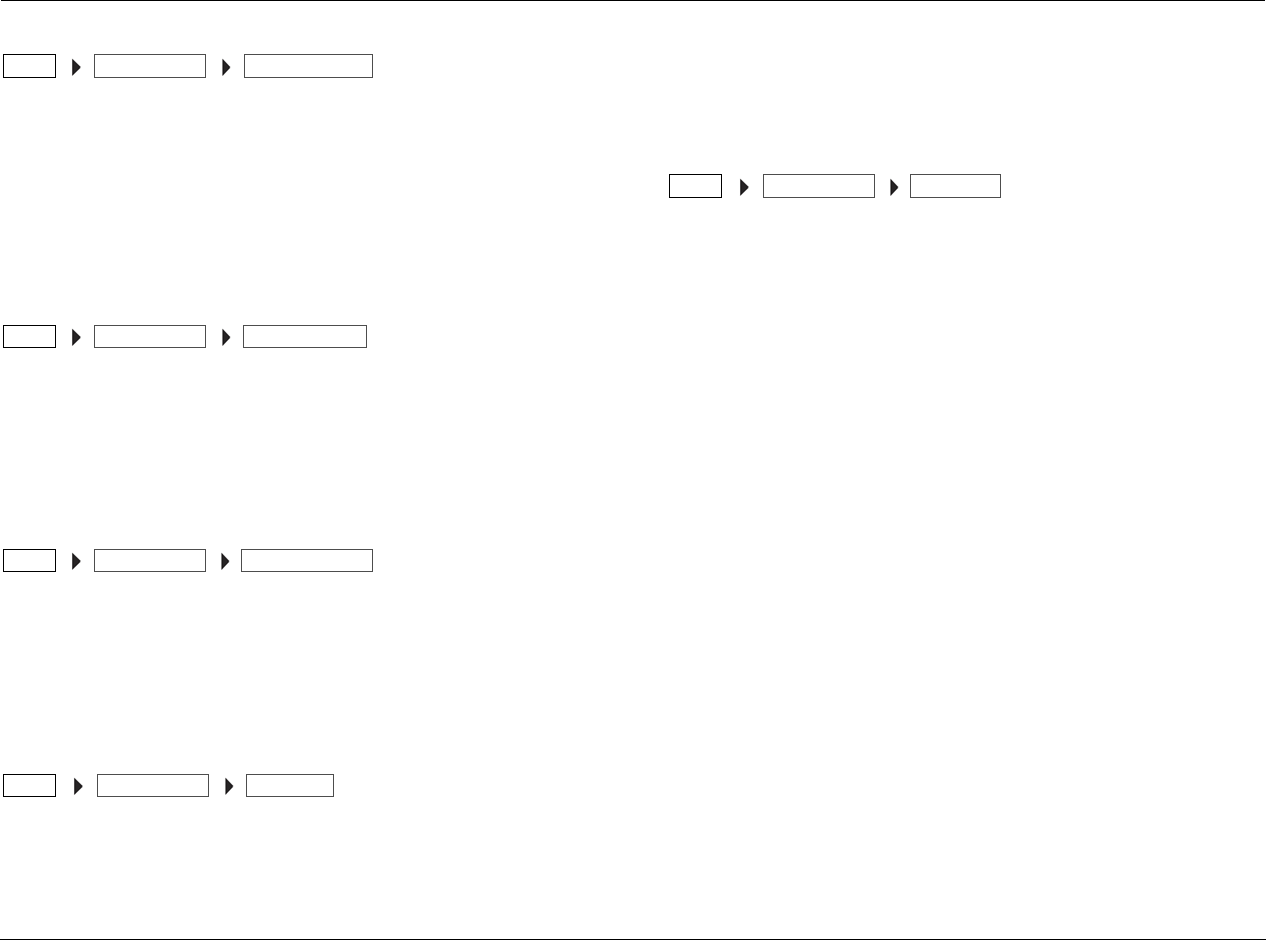
Setup Lexicon
3-18
A/D SAMPLE RATE 48 KHZ, 96 KHZ
The MV-5 converts the incoming analog audio signals to digital audio
for all audio processing. The A/D SAMPLE RATE parameter allows you
to select the sample rate of the A/D converters. Some surround
processing modes, such as those in the DSP Mode Family, are only
available at the 48 kHz sampling rate. This setting is only available for
incoming analog audio streams and does not apply to any of the
ANALOG BYPASS modes.
A/V SYNC DELAY 1 TO 180 mS
Delays the audio until it matches the on-screen video. Select a value
to activate an audio signal delay to compensate for video that is
delayed relative to the audio. The A/V sync delay range is 1 to 180 ms
in 1 ms increments. Each input has an independent A/V Sync Delay
parameter.
ADVANCED VIDEO
Selects the ADVANCED VIDEO menu, which provides fine-tuning
adjustments to the video output. For more information, refer to the
next section, “Advanced Video”.
Note: Most of the advanced video parameters are only available when the
V-Process parameter is set to FAROUDJA.
TRIGGER 2 OFF, ON
Selects the TRIGGER 2 parameter, which configures the Trigger
OUT 2 connector on the rear panel. This trigger output can be
configured independently for each input so that a trigger voltage
signal is sent to the Trigger Out 2 connector when a specific input is
selected. If the Trigger 2 parameter is set to ON, it will output its
voltage when the associated input is activated in the Main Zone. It
is not activated by Zone 2 input switching. The default for the
Trigger 2 parameter is OFF.
ZONE-2 OUT ANALOG, DOWN MIX
Identifies the type of audio that is sent to the Zone 2 outputs. The
ANALOG setting is a straight bypass of the Main Zone stereo analog
audio to the Zone 2 outputs. DOWNMIX provides a stereo
downmix of the incoming audio to the Zone 2 outputs.
DOWNMIX, which should be selected for digital or multi-channel
analog sources, is only available if the Main Zone has an input
selected that will accept a downmixed source. The ZONE 2 OUT
parameter is NOT input-specific; a selection made for one input will
be reflected in ALL inputs.
Note: If you have 5.1-channel or 7.1-channel ANALOG AUDIO assigned
to an Input using the BYPASS listening mode, only the Front Left and Front
Right channels will be sent to Zone 2 OUT with the ANALOG setting. In
this condition, DOWNMIX is not available.
The Main Zone and Zone 2 inputs are inter-related. For example,
there is only one HD input that is accessible in both Main Zone and
Zone 2; there are NOT two separate HD inputs. Therefore, to set
the ZONE 2 OUT in a Main Zone input, the same Zone 2 input
must also be selected.
DOWNMIX is only available if the following conditions exist:
• Zone 2 is ON (or the Zone 2 OFF button is not lit).
• Zone 2 has the same input selected as the Main Zone.
• If the Main Zone audio is ANALOG, it is not set to a BYPASS
listening mode.
INPUT SETUPSETUP A/D SAMPLE RATE
INPUT SETUPSETUP A/V SYNC DELAY
INPUT SETUPSETUP ADVANCED VIDEO
INPUT SETUPSETUP TRIGGER 2
INPUT SETUPSETUP ZONE-2 OUT

MV-5 Setup
3-19
If the Zone-2 OUT parameter is set to ANALOG and an input has
stereo analog audio assigned to it (ANALOG 1 to ANALOG 6
connectors), then choosing that input in Zone 2 will allow it to play
the assigned ANALOG audio, regardless of what is playing in the
Main Zone.
If the ZONE-2 OUT parameter is set to DOWNMIX, selecting an
input in Zone 2 will have one of the following results:
• If the Zone 2 input is the same as the Main Zone input, then
Zone 2 will output a downmix of the Main Zone audio.
• If the Zone 2 input is NOT the same as the Main Zone input,
but the Zone 2 DIG AUDIO IN parameter is the same as the
selected Main Zone input, then Zone 2 will output a downmix
of the Main Zone audio.
• If the Zone 2 input is NOT the same as the Main Zone input,
but the Zone 2 ANLG AUDIO IN parameter is set to 5.1
ANALOG or 7.1 ANALOG, then Zone 2 will output a downmix
of the Main Zone audio.
• If the Zone 2 input is NOT the same as the Main Zone input,
but the Zone 2 ANLG AUDIO IN parameter is set to any of the
six stereo analog input connectors, then Zone 2 will output the
independent analog audio for that input.
The PC, & DOCK inputs are special cases that do not quite function
exactly as noted above. The ZONE-2 OUT parameter is preset to
ANALOG and cannot be changed to DOWNMIX.
Since the PC & Dock inputs all operate independently of all other
inputs...
• Either may be selected in Zone 2 regardless of what is playing in
the Main Zone.
• Any combination of these two inputs can be selected in the
Main Zone and Zone 2, including selecting any one them for
both zones simultaneously.
• If either of these inputs is playing in the Main Zone, the other
ANALOG input can be chosen for Zone 2.
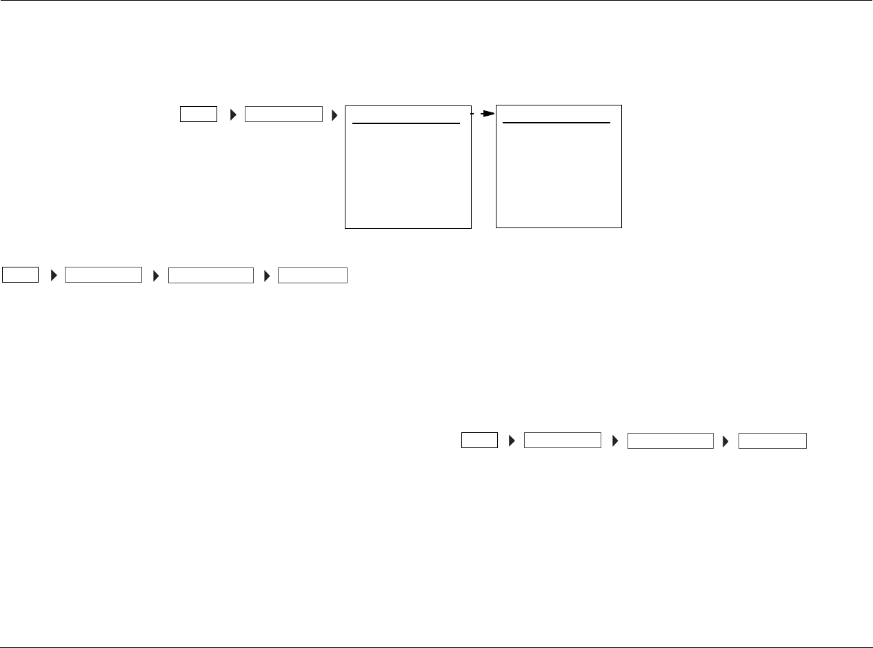
Setup Lexicon
3-20
ADVANCED VIDEO
Selecting the SETUP menu INPUT SETUP menu ADVANCED VIDEO option opens the ADVANCED VIDEO menu, a two-screen menu which
provides user-adjustable controls for sharpness, noise reduction, brightness, and other video fine-tuning.
Note: Most of the advanced video parameters are only available when the V-Process parameter is set to FAROUDJA.
INPUT TYPE
Identifies the type of device being used for the input source. Once
the selection is made, the advanced video settings will change to
default settings that are best suited for that type of device. Manual
changes to these settings may also be made. The input types
available for selection are:
• DVD – This setting is optimized for use with the output signal of
a typical DVD player.
• VCR – This setting is optimized for use with the output signal of
an analog videocassette recorder.
• DIG CABLE – This setting is optimized for use with digital cable
set-top boxes. Note: Even when a digital cable system is in use,
there may be a mix of digital and analog channels. Start with
this configuration and then change the advanced video options
as needed to tailor the output to your preferences.
• DIG SAT – This setting is optimized for use with digital satellite
system set-top boxes.
• ANLG CABLE – This setting is optimized for use with analog
cable set-top boxes.
• ANLG SAT – This setting is optimized for use with analog
satellite system set-top boxes.
• DIG CAM – This setting is optimized for use with digital
camcorders or still-image cameras.
• ANLG CAM – This setting is optimized for use with analog
camcorders.
Refer to the table on the following page for the default video source
settings.
SHARPNESS 0 TO 100
Adjusts the degree to which the enhancement circuits that adjust the
high-frequency content of the signal are applied. The setting acts on
the vertical and horizontal as well as luminance and chrominance
parameters to offer an enhanced depth in the picture as well as
greater small object detail. In general, the lower settings are appli-
cable for digital displays and sources, while the higher settings may
be preferred for CRT-based displays and digital sources. The
Sharpness adjustment range is 0 to 100 in single increments.
INPUT TYPE: VCR
SHARPNESS: 32
NOISE REDUCTION: ON
X-COLOR SUPPRESS: ON
DCDi INTERPOL: ON
FILM DETECTION: ON
FILM EDIT DETECT: ON
ADVANCED VIDEO 1
FLESHTONE NR: ON
COMPNT ENHANCE: ON
BRIGHTNESS: 100
CONTRAST: 100
COLOR: 100
TEST PAT: OFF
ADVANCED VIDEO 2
INPUT SETUPSETUP
INPUT SETUPSETUP ADVANCED VIDEO INPUT TYPE
INPUT SETUPSETUP ADVANCED VIDEO SHARPNESS
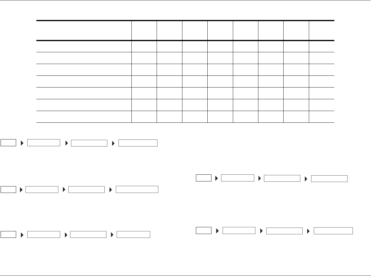
MV-5 Setup
3-21
NOISE REDUCTION OFF, ON
Reduces the video noise often present in analog input sources, when
ON is selected.
X-COLOR SUPPRESS OFF, ON
Reduces the cross-color interference that typically appears in
composite video sources as moire’ in finely detailed objects.
DCDi INTERPOL OFF, ON
Directional Correlation De-interlacing (DCDi) Interpolation is a
Faroudja technology that examines each pixel for the optimal
direction from which to interpolate the video information, with
regard to local edges. This adaptive process prevents the appearance
of staircasing and the jagged edges that are often visible with other
means of de-interlacing. This parameter toggles between ON and
OFF.
FILM DETECTION OFF, ON
Detects the presence of film-originated material so that the original
film-frame sequence may be recovered by weaving together the
appropriate video fields.
FILM EDIT DETECT OFF, ON
Applies additional processing when film-based material is detected
so that any disruption in the frame sequence of film-based material
FEATURE DVD VCR DIG
CABLE
DIG
SAT
ANLG
CABLE
ANLG
SAT
DIG
CAM
ANLG
CAM
Noise Reduction OFF ON OFF OFF ON ON OFF ON
X-Color Suppressor ONONONONONONONON
DCDi Interpolation ONONONONONONONON
Film Mode Detect ON ON ON ON ON ON ON ON
Film Mode Edit Detect ON ON ON ON ON ON ON ON
Composite Video Enhancement ONONONONONONONON
VCR Sync Time Enhancement ONONONONONONONON
INPUT SETUPSETUP ADVANCED VIDEO NOISE REDUCTION
INPUT SETUPSETUP ADVANCED VIDEO X-COLOR SUPPRESS
INPUT SETUPSETUP ADVANCED VIDEO DCDi INTERPOL
INPUT SETUPSETUP ADVANCED VIDEO FILM DETECTION
INPUT SETUPSETUP ADVANCED VIDEO FILM EDIT DETECT
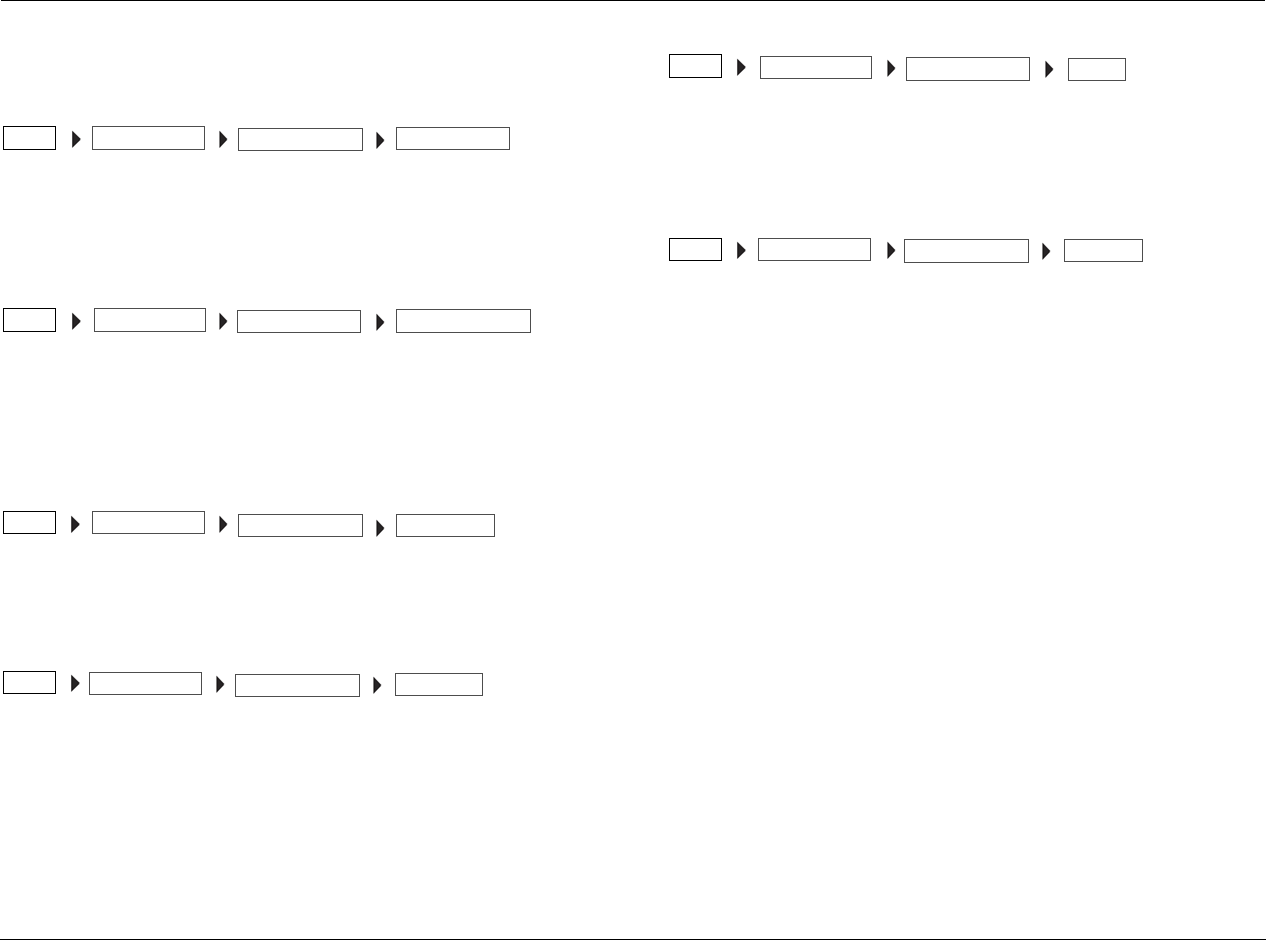
Setup Lexicon
3-22
due to video edits or overlay of video text over film is compensated
for by processing, before artifacts such as feathering may appear.
FLESHTONE NR OFF, ON
Selects the Fleshtone Noise Reduction parameter, which preserves
the detail in faces and flesh tones while reducing noise in the total
picture.
COMPONENT ENHANCE OFF, ON
Selects the Component Video Enhance parameter, which processes
incoming component video signal to adjust the high-frequency
content of the signal resulting in enhanced depth in the picture as
well as greater small object detail.
BRIGHTNESS 50 TO 150
Changes the video level to a darker or brighter setting. The
BRIGHTNESS adjustment range is 50 to 150 in single increments.
CONTRAST 50 TO 150
Changes the black level of the video to compensate for poor
contrast. The CONTRAST adjustment range is 50 to 150 in single
increments.
COLOR 50 TO 150
Changes the color of the video to compensate for over- or under-
color saturation conditions. The Color adjustment range is 50 to 150
in single increments.
TEST PATTERN
Selects the Test Patterns parameter, which provides a series of
standard test signals that are used during the factory testing of the
MV-5. While these test patterns can be viewed, they are not
designed for user adjustment and will not show any visible signs of
adjustment to the video display or to the MV-5 settings. The test
patterns are:
• Color Bars – these are a variation of the traditional split-field
color bars used to check the internal settings for luminance/
chrominance voltage levels with respect to the eight basic
colors.
• Triangle Fixed – this test pattern puts two opposing triangles on
the screen, with a black triangle on the right and a white
triangle on the left, to test aspects of the pull-down logic
software.
• Triangle Flashing – this test pattern also puts two opposing
black and white triangles on the screen, but it flashes them at a
high frame rate, to test the 3/2 pull-down edit detection and
other aspects of the processor and interpolation software.
• Ramp/Square – this complex pattern uses a variety of fixed and
pulsating gray-scale images to test different aspects of the 3/2
pull-down edit detection and other aspects of the processor
and interpolation software.
Note: If a test pattern is selected, the menu cannot be viewed on the
display until the test pattern is turned off. Exiting the menu structure will
INPUT SETUPSETUP ADVANCED VIDEO FLESHTONE NR
INPUT SETUPSETUP ADVANCED VIDEO COMPNT ENHANCE
INPUT SETUPSETUP ADVANCED VIDEO BRIGHTNESS
INPUT SETUP
SETUP ADVANCED VIDEO CONTRAST
INPUT SETUP
SETUP ADVANCED VIDEO COLOR
INPUT SETUPSETUP ADVANCED VIDEO TEST PAT
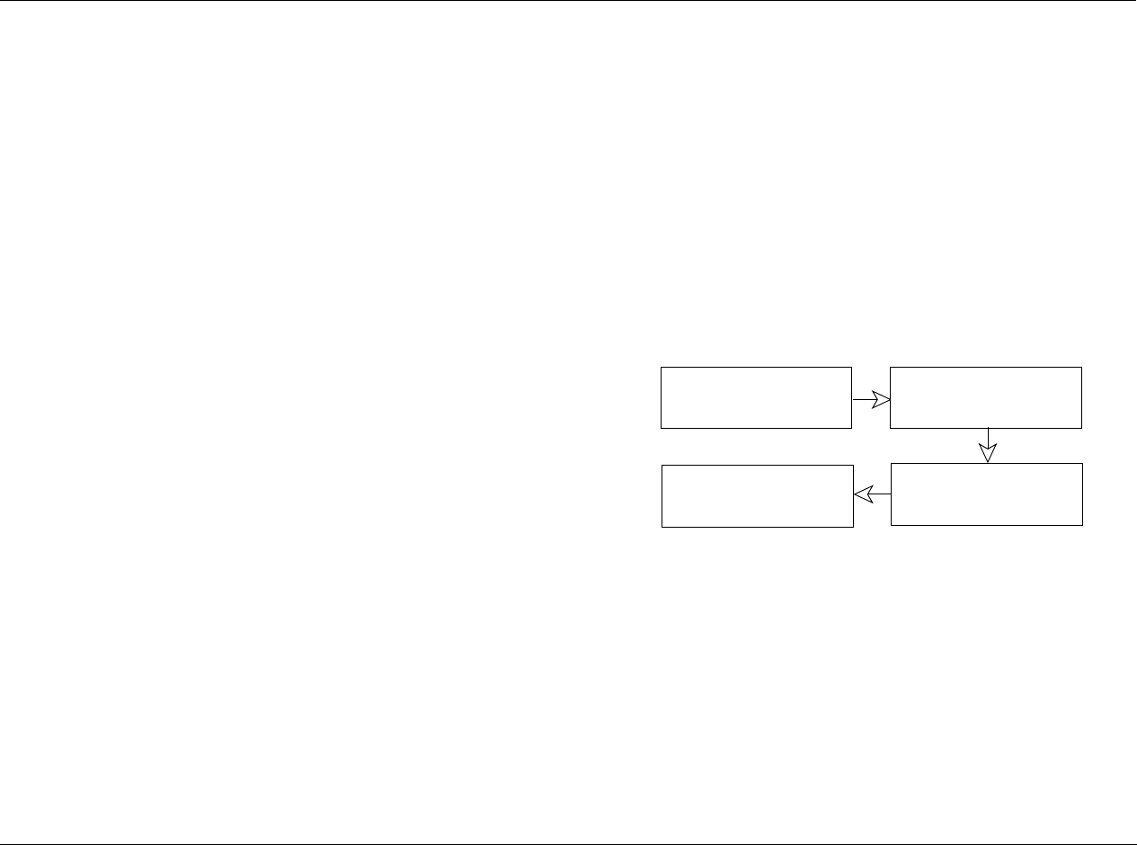
MV-5 Setup
3-23
clear the test pattern. While test patterns are active, the advanced video
settings can be changed even though the OSD is off.
The MV-5 has a large selection of listening modes to choose from. The list of available listening modes is broken into two parts - the Mode Family
and the Mode. The available listening modes vary depending upon the Mode Family selections, the input setup, and the incoming data stream.
The MV-5 also features the ability to turn off selected listening mode families so that those options do not appear in the list of available listening
modes. See the following section, “Surround Configuration”, for more information. The MV-5 also features the ability to modify elements of the
Dolby listening modes, PLIIx and PLII, to better suit your listening preference. See the “Dolby Configuration” section found later in this chapter for
more information.
SELECTING A LISTENING MODE
The Input Setup menu allows the user to select the initial listening
mode and mode family that will be applied to any incoming data
stream on that specific input. However, setting the input Mode
Family and Mode parameters does not prevent other listening modes
from being available through the Mode buttons.
The Front Panel Mode and buttons allow the user to quickly
scan through the available listening modes in the selected family for a
given input or incoming data stream. The Remote Control Channel
and buttons perform the same function.
To select a different Mode Family, the Remote Control touch screen
must be set to the first page of the LEX menu. Then selecting the
DOLBY, DTS, DSP, or STER soft button on the remote control switches
the Mode button selections to any listening modes available for each
of those families, respectively.
The MV-5 process of signal identification and listening mode
selection is shown below:
DTS + DOLBY LISTENING MODES
When a DTS soundtrack is playing, the Mode Family menu for DTS
contains two options. The DTS selection provides the currently
available DTS listening modes. The Dolby selection contains two
additional listening modes: DTS + PLIIx Film and DTS + PLIIx Music.
Note: These DTS + Dolby listening modes are ONLY available when the
incoming data stream is DTS.
Incoming Signal MV-5 identifies
incoming signal
MV-5 identifies which
been turned off
surround modes have
MV-5 builds the
available mode list
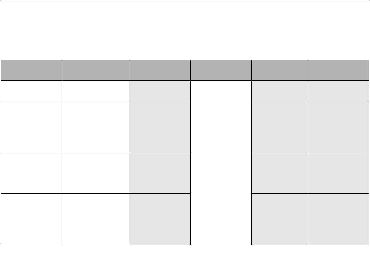
Setup Lexicon
3-24
AVAILABLE LISTENING MODES
The following table provides a complete listing of the listening modes available for each of the incoming audio or video formats currently available.
Shaded out cells indicate that there are no available modes in that Mode Family for that specific incoming data stream.
Note: The table identifies all of the possible formats, but depending upon the Input setup and the Surround Configuration of the MV-5, all of these modes may
not be available for selection.
Incoming DOLBY
Datastream Dolby DTS Logic 7 DSP Stereo
Dolby Digital 1.0 VS 2-SP REF & WIDE
DOLBY DIGITAL
DOLBY D STEREO
Logic 7 7CH FILM
Logic 7 7CH MUSIC
Logic 7 5CH FILM
Logic 7 5CH MUSIC
Dolby Digital 2.0 PLIIx Film, Music, & Game
PLII Film, Music, & Game
Pro Logic
VS 2-SP REF & WIDE
VS 3-SP REF & WIDE
VS 4-SP WIDE
VS 5-SP WIDE
DOLBY DIGITAL
Dolby Digital 4.1 PLIIx Film & Music
Digital EX
DOLBY DIGITAL
DOLBY D STEREO
VS 2-SP REF & WIDE
VS 4-SP WIDE
Dolby Digital 5.1 D+PLIIX Film & Music
Digital EX
DOLBY DIGITAL
DOLBY D STEREO
VS 2-SP REF & WIDE
VS 3-SP REF & WIDE
VS 4-SP WIDE
VS 5-SP WIDE
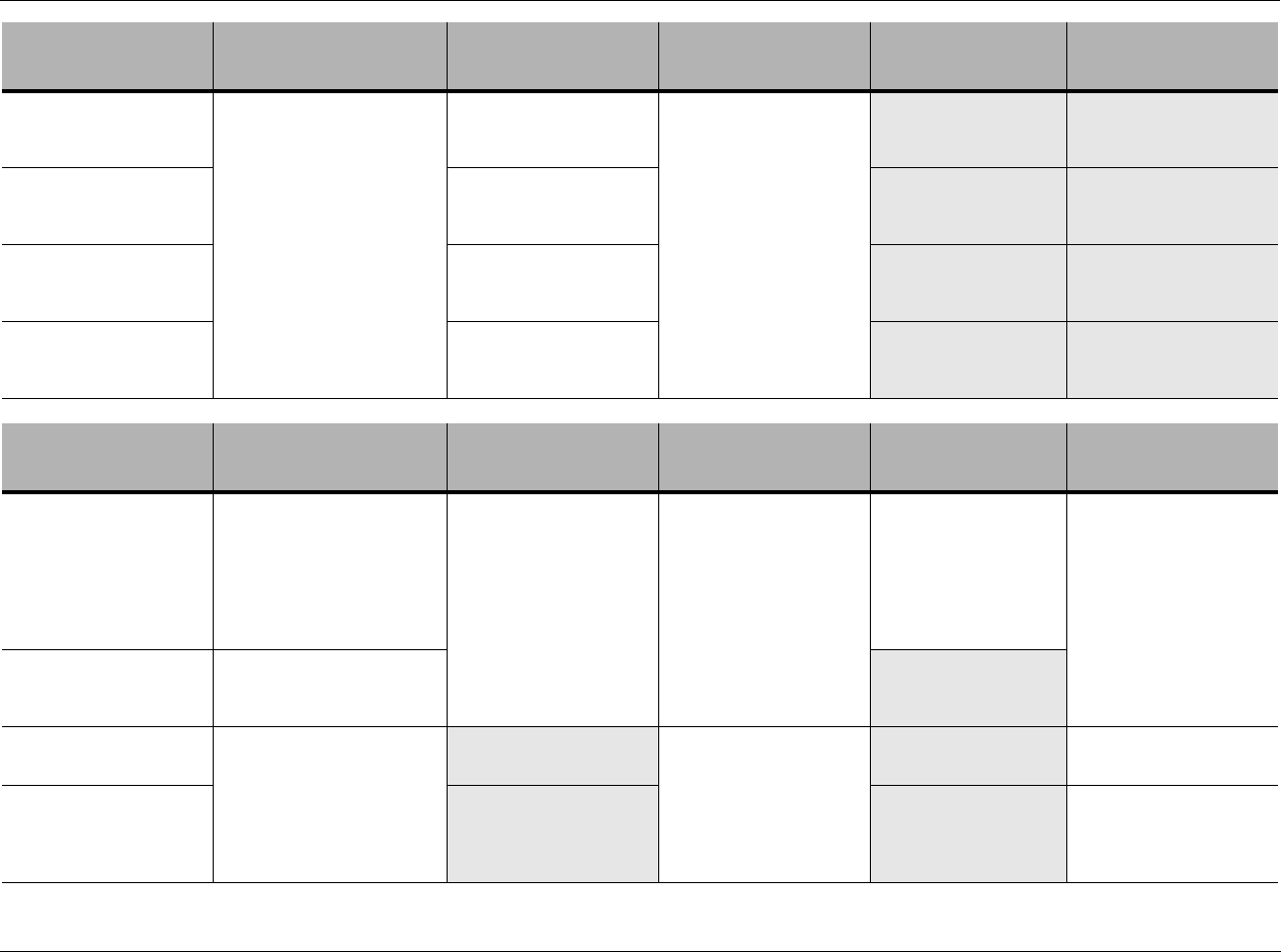
MV-5 Setup
3-25
*The 2-ch Bypass mode is ONLY available if the Tone Controls parameter is set to OFF.
Incoming DTS
Datastream Dolby DTS Logic 7 DSP Stereo
DTS 5.1 MATRIX
DTS+PLIIx Film & Music*
*These modes are only
available when a DTS source is
playing and the Dolby Mode
Family button is pressed on
the remote.
DTS-ES MATRIX
DTS
DTS STEREO
Logic 7 7CH FILM
Logic 7 7CH MUSIC
Logic 7 5CH FILM
Logic 7 5CH MUSIC
DTS 96/24 DTS 96/24
DTS 96/24 ST
DTS NEO:6
DTS 6.1 DISCRETE DTS-ES DISCRETE
DTS
DTS STEREO
DTS 5.1 and
DTS 20-bit 5.1 ch CD
DTS NEO:6
DTS
DTS STEREO
Incoming ANALOG
Datastream Dolby DTS Logic 7 DSP Stereo
Analog, 2-channel
48kHz sample rate
PLIIx Film, Music, & Game
PLII Film, Music, & Game
P r o L o g i c
V S 2- S P RE F & WI D E
VS 3 - SP R E F & W I DE
V S 4 - S P W I D E
VS 5-SP WIDE
Neo 6: 6ch Cinema
Neo 6: 6ch Music
Neo 6: 5ch Cinema
Neo 6: 5ch Music
Neo 6: 3ch Cinema
Logic 7 7CH FILM
Logic 7 7CH MUSIC
Logic 7 5CH FILM
Logic 7 5CH MUSIC
Hall 1 5ch
Hall 1 6ch
Hall 2 5ch
Hall 2 6ch
2-ch Stereo
2-ch Bypass*
5-ch Stereo
7-ch Stereo
Analog, 2-channel
96kHz sample rate
PLIIx Film, Music, & Game
PLII Film, Music, & Game
Pro Logic
Analog, 5-channel
48kHz & 96kHz sample rate
PLIIx Film & Music Logic 7 7CH FILM
Logic 7 7CH MUSIC
5-CHANNEL
5.1-ch Bypass
Analog, 7-channel
48kHz & 96kHz sample rate
5-CHANNEL
5.1-ch Bypass
7-CHANNEL
7.1-ch Bypass
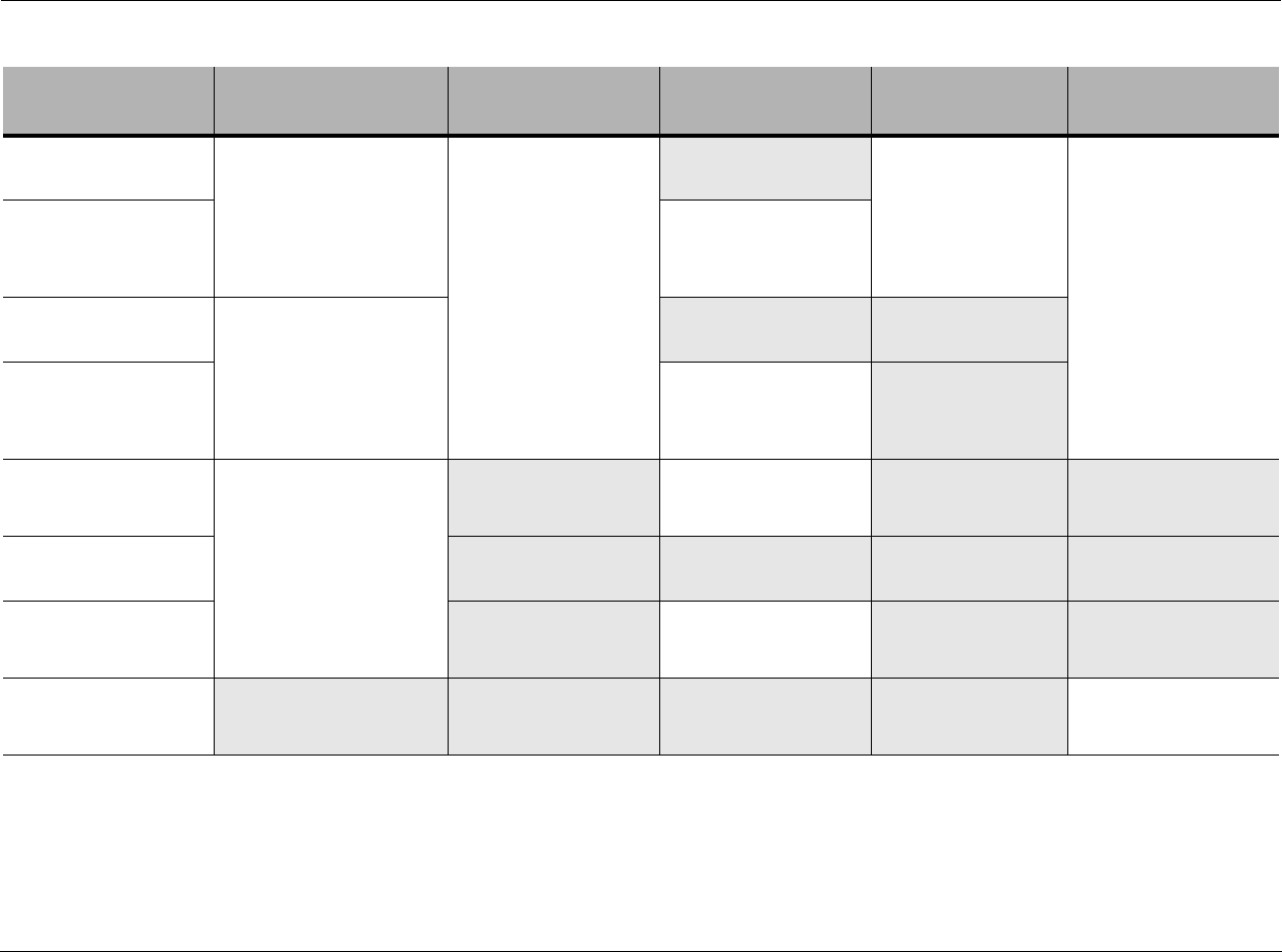
Setup Lexicon
3-26
**With PCM 5.1 audio input, one additional listening mode is available - the AUDIO STATUS menu indicates that the audio is PCM 3/2.1, the mode family is PCM MULTI, and the mode is
STANDARD, which applies only bass management and tone controls to the incoming PCM 5.1 audio.
Incoming PCM
Datastream Dolby DTS Logic 7 DSP Stereo
PCM 32kHz PLIIx Film, Music, & Game
PLII Film, Music, & Game
Pro Logic
VS 2-SP REF & WIDE
VS 3-SP REF & WIDE
VS 4-SP WIDE
VS 5-SP WIDE
Neo 6: 6ch Cinema
Neo 6: 6ch Music
Neo 6: 5ch Cinema
Neo 6: 5ch Music
Neo 6: 3ch Cinema
Hall 1 5ch
Hall 1 6ch
Hall 2 5ch
Hall 2 6ch
2-ch Stereo
5-ch Stereo
7-ch Stereo
PCM 44.1/48kHz
2-channel
Logic 7 7CH FILM
Logic 7 7CH MUSIC
Logic 7 5CH FILM
Logic 7 5CH MUSIC
PCM 88.2kHz
2-channel PLIIx Film, Music, & Game
PLII Film, Music, & Game
Pro Logic
PCM 96kHz
2-channel
Logic 7 7CH FILM
Logic 7 7CH MUSIC
Logic 7 5CH FILM
Logic 7 5CH MUSIC
PCM 44.1/48kHz
5.1-channel**
PLIIx Film & Music
PCM MULTI**
Logic 7 7CH FILM
Logic 7 7CH MUSIC
PCM MULTI**
PCM 88.2kHz
5.1-channel**
PCM 96kHz
5.1-channel**
Logic 7 7CH FILM
Logic 7 7CH MUSIC
PCM MULTI**
PCM 176.4/192kHz 2-ch Stereo
5-ch Stereo
7-ch Stereo

MV-5 Setup
3-27
LISTENING MODE DESCRIPTIONS
The following table provides a brief description of each listening mode.
Logic 7 Film
Logic 7 Music
A proprietary Harman International format, Logic 7 is an advanced mode that extracts the maximum surround information from either surround-
encoded programs or conventional stereo material. Film 7.1 and Music 7.1 are tailored specifically for use with rear speakers, while Film 5.1 and Music
5.1 are specifically formatted for use without rear speakers. The Film modes should be used with any source that contains Dolby Surround or similar
matrix encoding to experience increased center channel intelligibility and more accurate placement of sounds with fades and pans. The Music modes
enhance the listening experience by presenting a wider front soundstage and greater rear ambience. Both Logic 7 modes also direct low-frequency
information to the subwoofer (if installed and configured) to deliver maximum bass impact. Logic 7 adds additional bass enhancement that circulates
low frequencies in the 40 Hz to 120 Hz range to the front and surround speakers to deliver a less localized soundstage that seems broader and wider
than when the subwoofer is the sole source of bass energy.
Dolby Digital Available only with digital input sources encoded with Dolby Digital data. It provides up to five separate main audio channels and a special dedicated
low-frequency effects channel. This mode does not use the rear speakers.
Dolby Digital EX Available when the receiver is configured for 7.1-channel operation, Dolby Digital EX is an extended version of Dolby Digital. When used with movies
or other programs that have special encoding, Dolby Digital EX reproduces specially-encoded soundtracks so that a full 7.1 sound field is available.
Even if a source does not contain specific EX encoding, the special algorithm may be used to derive a 7.1-channel output.
Dolby Pro Logic II
Film
Music
Game
Pro Logic
Dolby Pro Logic II decodes full-range, discrete, left, center, right, right surround, and left surround cannels from matrix surround-encoded programs
and conventional stereo sources. The Dolby Pro Logic II Film mode is optimized for movie soundtracks, while the Pro Logic II Music mode should be
used with musical selections. The Pro Logic II Game mode is designed to enhance the soundtrack of video games for either dedicated consoles or com-
puters. The Pro Logic mode re-creates the original Pro Logic processing for those who prefer that presentation format.
Dolby Pro Logic IIx
Film
Music
Game
Dolby Pro Logic IIx is the latest extension of Dolby Laboratory’s benchmark matrix surround technology, which creates a discrete 7.1 sound field from
matrix surround or two-channel stereo sources when your system is configured for surround back speakers. Film, Music, and Game versions are
available that customize the processing to the type of source in use. These modes may also be used to create 7.1 sound fields from 5.1 digital
soundtracks.
Dolby Virtual Speaker
Reference
Wide
Dolby Virtual Speaker technology uses a next-generation advanced algorithm to reproduce the dynamics and surround sound effects of a precisely
placed 5.1-channel speaker system using only front left and right speakers. In the Reference mode, the apparent width of the sound across the front
image is defined by the distance between the two speakers. The Wide mode provides a wider, more spacious front image when the two speakers are
close together. Depending upon the number of speakers available in your system, a variety of different sound field options are available for both the
Reference and Wide modes.
DTS 5.1 When the speaker configuration is set for 5.1-channel operation, the DTS 5.1 mode is available when DVD, audio-only music, or laser discs encoded
with DTS data are played. DTS 5.1 provides up to five separate main audio channels and a special dedicated low-frequency effects channel.
DTS-ES 6.1 Matrix
DTS-ES 6.1 Discrete
When the speaker configuration is set for 7.1-channel operation, playback of a DTS-encoded program source will automatically trigger the selection of
one of the two DTS-ES modes. Newer discs with special DTS-ES Discrete-encoding will be decoded to provide six discrete, full-bandwidth channels
plus a separate low-frequency effects channel. All other DTS discs will be decoded using the DTS-ES Matrix mode, which creates a 6.1-channel sound
field from the original 5.1-channel soundtrack.
Setup Lexicon
3-28
5.1-CHANNEL & 7.1-CHANNEL DIRECT INPUTS
There are four listening modes available for use with surround
sources such as DVD-Audio, SACD, HD-DVD, or Blue-ray players.
These listening modes are for use when the MV-5 8-channel input is
in use. We recommend you use these listening modes under the
following conditions:
• 5.1 BYPASS - Use this listening mode when the Surround Back
L/R inputs are NOT in use and the input source device has its
own internal bass management system. The incoming audio
stream passes from the source directly through to the volume
control without any analog-to-digital conversion. This mode
also mutes the unusued input jacks to prevent unwanted noise
from interfering with the system performance.
• 5-CHANNEL - Use this listening mode when the Surround Back
L/R inputs are NOT in use and the input source device does
NOT have its own internal bass management system. In this
mode, the analog source is converted to digital so that it uses
the same bass management options for the direct input as used
for all other inputs. This mode also mutes the unusued input
jacks to prevent unwanted noise from interfering with the
system performance.
• 7.1 BYPASS - Use this listening mode when all eight channels
direct inputs are in use and the input source device has its own
internal bass management system. The incoming audio stream
passes from the source directly through to the volume control
without any analog-to-digital conversion.
• 7-CHANNEL - Use this listening mode when all eight channels
direct inputs are in use and the input source device does NOT
have its own internal bass management system. In this mode,
the analog source is converted to digital so that it uses the same
bass management options for the direct input as used for all
other inputs.
DTS Neo:6 Cinema
DTS Neo:6 Music
These two modes are available when any analog source is playing to create a three-channel, five-channel, or six-channel surround presentation from
conventional Matrix-encoded and traditional Stereo sources. Select the Cinema version of the Neo:6 when a program with any type of Matrix sur-
round encoding is present. Select the Music version of Neo:6 for optimal processing when a non-encoded, two-channel stereo program is being
played.
DTS Neo:6 The DTS Neo:6 mode is designed for use with matrix-encoded digital signals. This mode is available when Digital DTS 96/24, DTS 5.1, and DTS 20-bit
5.1 CH CD data streams are active. DTS Neo:6 derives six channels when both side and rear speakers are present (rear speakers will be in parallel). It
derives five channels when only side speakers are present.
DTS 96/24 DTS 96/24 is available on specially-encoded (and labeled) optical discs that offer five channels of audio with a 96kHz sampling rate that delivers greatly
improved audio performance. When a DTS 96/24 disc is in use and the player is connected with a digital link, the mode is selected automatically.
Hall 1 & Hall 2 The Hall modes, for both 5-channel and 7-channel systems, create sound fields that resemble a small-(Hall 1) or medium-sized (Hall 2) concert hall.
5-Channel Stereo
7-Channel Stereo
This mode takes advantage of multiple speakers to place a stereo signal at both the front and back of a room. Ideal for playing music in situations such
as a party, it places the same signal at the front-left and surround-left, and front-right and surround-right speakers. The center channel is fed a summed
mono mix of the in-phase material of the left and right channels. If the MV-5 has been configured for 6.1-/7.1-channel operation, both of these options
are available for selection. If the MV-5 has been configured for 5.1-channel operation, only the 5-Channel Stereo option is available.
2-Channel Stereo This mode turns off all surround processing and presents pure left- and right-channel stereo programs. The bass management processing that routes
low frequencies to the subwoofers is still active.

MV-5 Setup
3-29
DTS & DOLBY STATUS DISPLAYS
The upper right-hand corner of the front panel 2-line display may
indicate status information regarding the incoming source. If a
Dolby or DTS source in input and the MV-5 is configured to a
surround system, the following status indicators may be displayed
to indicate the state of the incoming source:
• ES-ON: Indicates when an encoded DTS signal, discrete or
matrix, is input to the surround back channels. “ON” indicates
that the condition exists, or is active; “OF” indicates that the
condition does not exist, or is off.
• DS-ON: Indicates when the input signal is encoded with Dolby
Surround under the Dolby 2.0 standard. “ON” indicates that
the condition exists, or is active; “OF” indicates that the
condition does not exist, or is off.
• EX-ON: Indicates when Dolby Surround EX is input with the
digital stream, if a surround channel (3/2 or 2/2) exists. “ON”
indicates that the condition exists, or is active; “OF” indicates
that the condition does not exist, or is off.
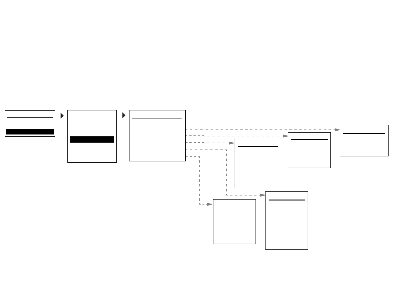
Setup Lexicon
3-30
SURROUND CONFIGURATION
Selecting the SETUP menu SURROUND CONFIG option opens the Surround Configuration menu, which is used to customize the list of available
listening modes that can be applied to incoming signals. Each Mode Family has a subset of available listening modes that can be turned off. If the
listening mode is set to OFF, then the applicable listening modes in that family are not available for selection from the mode buttons. If the listening
mode is ON, then the applicable listening modes in that family are available for selection.
These are not input-specific settings, if a Mode Family option is turned off, it is removed from the list of available listening modes for ALL inputs, and
regardless of the incoming data stream. Some modes, such as Dolby Digital, DTS, and the Stereo modes in the PCM menus, cannot be excluded
from the mode selections.
Note: The Logic 7 Default parameter is the one exception in the Surround Configuration menu - this parameter has different functionality, as described on the
following page.
DOLBY VIRTUAL: OFF
STEREO DOWNMIX: ON
DOLBY MULTI-CHANNEL
LOGIC 7: ON
HALL: ON
5/7 CH STEREO: ON
DTS-ES DISCRETE: ON
LOGIC 7: ON
SURROUND CONFIG
LOGIC 7 DEFAULT: ON
DOLBY MULTI-CHANNEL
DOLBY 2.0
DTS
PCM 44.1/48 kHz
PCM 96kHz
MAIN MENU
AUDIO CONTROLS
VIDEO CONTROLS
DISPLAY SETUP
SPEAKER/EQ SETUP
INPUT SETUP
SURROUND CONFIG
DOLBY CONFIG
MUTE LEVELS
POWER ON SETTINGS
SETUP
SETUP
DOLBY PLII: ON
DOLBY VIRTUAL: OFF
DOLBY 2.0
DOLBY PLIIx: ON
DTS 96/24: ON
DTS-ES MATRIX: ON
DTS
DTS NEO:6: ON
LOGIC 7: ON
STEREO DOWNMIX: ON
DOLBY VIRTUAL: OFF
LOGIC 7: ON
DOLBY PLIIx: ON
PCM 44.1/48 kHz
DOLBY PLII: ON
DTS NEO:6: ON
5/7 CH STEREO: ON
LOGIC 7: ON
DOLBY PLIIx: ON
PCM 96kHz
DOLBY PLII: ON
DTS NEO:6: ON

MV-5 Setup
3-31
LOGIC 7 DEFAULT OFF, ON
Allows the user to choose Logic 7 as the default surround mode for
all incoming audio signals. If this parameter is OFF, then the MV-5
selects the native format of the incoming signal as the default
listening mode. If set to ON, then all incoming audio signals are
defaulted to the Logic 7 listening modes.
Setting the Logic 7 Default to ON does not prevent other listening
modes from being available through the mode buttons. Selecting
the DOLBY, DTS, DSP, or STER soft button on the remote control
switches the Mode menu selections to any listening modes available
for those families.
Note: The Logic 7 Default is the only menu item in the Surround Config
menu that has different functionality.
SURROUND CONFIGSETUP LOGIC 7 DEFAULT
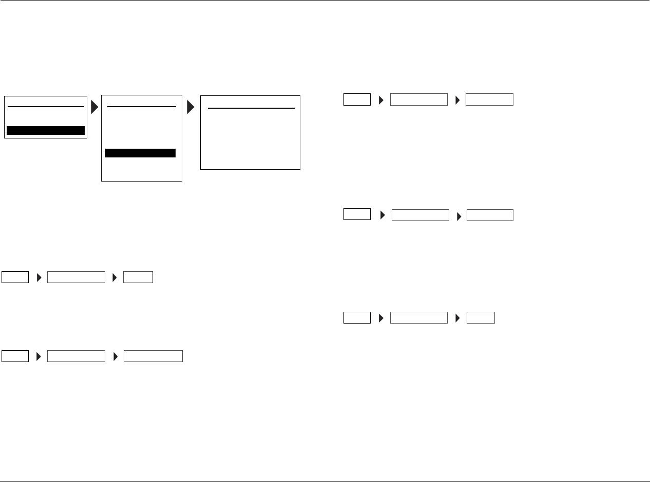
Setup Lexicon
3-32
DOLBY CONFIGURATION
Selecting the SETUP menu DOLBY CONFIG option opens the Dolby Configuration menu, which is used to configure the Dolby surround modes for
optimum performance.
Note: The Dolby Configuration only applies to the Dolby PLII Music and
Dolby PLIIx Music listening modes. The Dolby Pro Logic IIx mode requires
a 7.1-channel configured system.
MODE PLII, PLIIx
Selects the MODE parameter, which chooses between the Dolby PLII
Music and Dolby PLIIx Music listening modes.
CENTER WIDTH 0 TO 7
Adjusts the balance of the vocal information in the front soundstage
between the center and front left/right speakers. The higher settings
spread the center channel sound more broadly into the left and right
channels while a lower number produces a tigher center channel
presentation. The Center Width range is 0 to 7 in single increments.
DIMENSION R-1, R-2, R-3, O, F-1, F-2, F-3
Alters the perceived depth of the surround field by creating a
shallower presentation (F-1 to F-3) that appears to move the center
of the sound field towards the front of the room or a deeper
presentation (R-1 to R-3) that appears to move the sound field
towards the rearof the room.
PANORAMA OFF, ON
Appears to increase the sound presentation along the sides of the
room by extending the stereo image to include surround channel
signals, which enhances the sense of surround sound by creating a
“wraparound” effect with side wall imaging.
NIGHT OFF, MID, MAX
Adjusts the audio settings for Night mode. The Night mode uses
special processing to preserve the dynamic range and full intelligibility
of a movie soundtrack while reducing the peak level. This prevents
abruptly loud transitions from disturbing others, without reducing the
sonic impact of a digital source. Use the MID setting for mild
compression and the MAX setting for more severe compression.
MAIN MENU
AUDIO CONTROLS
VIDEO CONTROLS
DISPLAY SETUP
SPEAKER/EQ SETUP
INPUT SETUP
SURROUND CONFIG
DOLBY CONFIG
MUTE LEVELS
POWER ON SETTINGS
SETUP
SETUP DOLBY CONFIGURATION
MODE: DOLBY PLII MUSIC
CENTER WIDTH:3
DIMENSION: 0
PANORAMA: OFF
NIGHT: OFF
DOLBY CONFIGSETUP MODE
DOLBY CONFIGSETUP CENTER WIDTH
DOLBY CONFIGSETUP DIMENSION
DOLBY CONFIG
SETUP PANORAMA
DOLBY CONFIGSETUP NIGHT
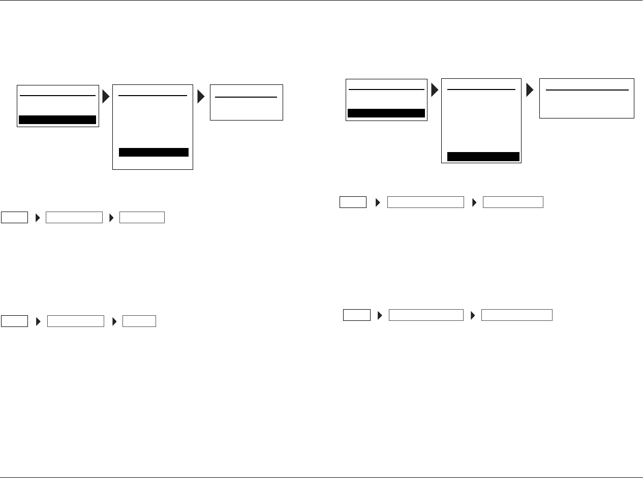
MV-5 Setup
3-33
MUTE LEVELS
Selecting the SETUP menu MUTE LEVELS option opens the Mute
Levels menu, which is used to adjust the mute levels of both the Main
Zone and Zone 2 audio outputs.
MAIN ZONE FULL, -10, -20, -30, -40dB
Allows you to choose different levels of attenuation for Main Zone
audio muting. The FULL setting completely mutes the box. The
other available settings perform incremental muting. The display
volume value does not change when mute is activated.
ZONE 2 FULL, -10, -20, -30, -40dB
Allows you to choose different levels of attenuation for Zone 2 audio
muting. The FULL setting completely mutes the box. The other
available settings perform incremental muting. The display volume
value does not change when mute is activated. On the remote
control, Zone 2 mute is only available when the soft button for Zone
2 is selected.
POWER ON SETTINGS
Selecting the SETUP menu POWER ON SETTINGS option opens the
Power On Settings menu, which provides user preferences to the
power on volume and dock auto power settings.
POWER ON VOL LAST, -80dB TO -10dB IN 1dB INCREMENTS
Identifies the starting volume level when the MV-5 is powered on.
The Last parameter sets the volume to the same volume that existed
when the unit was put into stand-by or powered off from the rear
panel switch. The Power On Volume can be set from –80dB to –10dB
in 1dB increments.
DOCK AUTO POWER OFF, ON
If the Dock Auto Power parameter is set to ON, then if an iPod is
playing when plugged into the Dock, it will take the MV-5 out of
Stand-by mode and select the Dock input. If the Dock Auto Power
parameter is set to OFF, then the MV-5 does not respond when a
running iPod is plugged into the Dock.For more information about
the Dock, refer to the Section 5: Tuner, PC, and Dock Controls.
Note: If the Main Zone is OFF when the RV-5 is put into Standby, when
the iPod is plugged into the Dock, the RV-5 will power up but the Main
Zone will remain OFF. The user will need to manually select the DOCK
input at that point.
MAIN MENU
AUDIO CONTROLS
VIDEO CONTROLS
DISPLAY SETUP
SPEAKER/EQ SETUP
INPUT SETUP
SURROUND CONFIG
DOLBY CONFIG
MUTE LEVELS
POWER ON SETTINGS
SETUP
SETUP MUTE LEVELS
MAIN ZONE: -30dB
ZONE-2: -30dB
MUTE LEVELSSETUP MAIN ZONE
MUTE LEVELSSETUP ZONE-2
MAIN MENU
AUDIO CONTROLS
VIDEO CONTROLS
DISPLAY SETUP
SPEAKER/EQ SETUP
INPUT SETUP
SURROUND CONFIG
DOLBY CONFIG
MUTE LEVELS
POWER ON SETTINGS
SETUP
SETUP POWER ON SETTINGS
POWER ON VOL: -30dB
DOCK AUTO POWER: ON
POWER ON SETTINGSSETUP POWER ON VOL
POWER ON SETTINGSSETUP DOCK AUTO POWER

Setup Lexicon
3-34

4
Audio & Video Controls
Audio Controls............................................................................4-2
Video Controls ............................................................................4-4
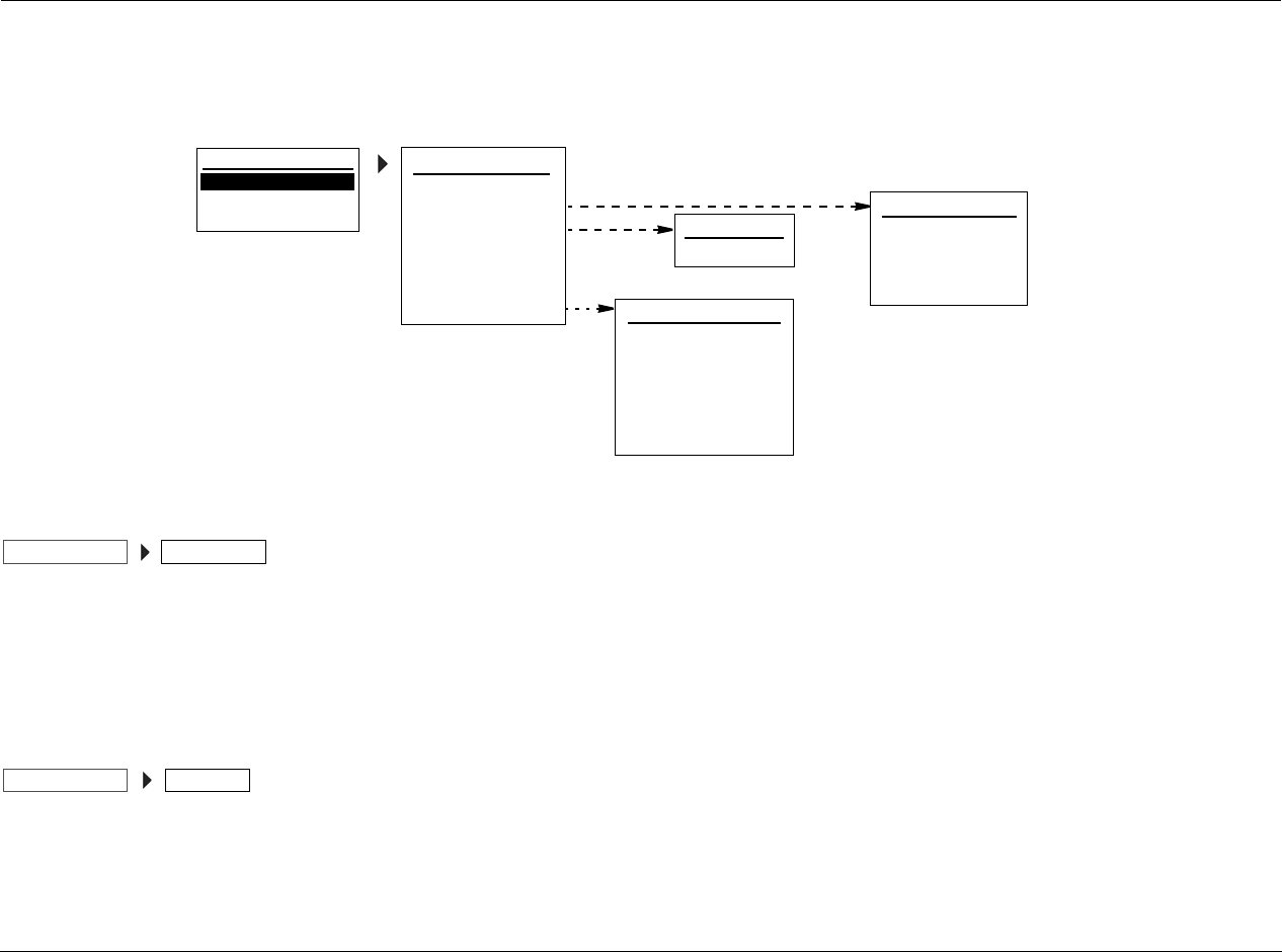
Audio & Video Controls Lexicon
4-2
AUDIO CONTROLS
Selecting AUDIO CONTROLS opens the AUDIO CONTROLS menu. All of the Audio Controls interact with the autocalibration settings, except for
the Audio Status parameter.
AUTO EQ OFF, ON
If the AUTOCAL process is performed and the settings are saved,
then the Auto EQ parameter identifies if the saved AUTOCAL
settings are being actively applied to the system. When the Auto EQ
parameter is OFF, the AUTOCAL settings are not applied. The EQ
Adjust parameter is also not applied.
EQ PRESET PRESET 1, PRESET 2, PRESET 3, USER
Identifies the three preset locations where the AUTOCAL settings
are saved, and displays the state of each preset (saved or unused).
The Active PS, or Active Preset, identifies the preset location that is
currently active if the AUTO EQ parameter is set to ON for any
input. The Active Preset can be set to any of the three saved preset
locations. The preset location listed under the Active Preset
parameter indicates which of the saved autocal settings are
currently in use.
To load a different saved preset into the system:
1. Decide which saved Preset location you want to load.
2. Select ACTIVE PS from the EQ PRESET menu.
3. Use the or cursors to select the Preset location you want
to load.
4. Press the cursor to save the selection.
AUDIO CONTROLS
EQ PRESET
TONE CONTROLS: OFF
BASS: 0dB
TREBLE: 0dB
AUDIO STATUS
EQ PRESET
PRESET 1: FACTORY
ACTIVE PS: USER
PRESET 2: FACTORY
PRESET 3: FACTORY
AUDIO STATUS
INPUT: HD
MODE FAMILY: LOGIC 7
AUDIO: - - -
NAME:
MODE: MUSIC 5.1
CONNECTOR: ANALOG 3
MAIN MENU
AUDIO CONTROLS
VIDEO CONTROLS
SETUP EQ ADJUST
HF SHELF: 0dB
AUTO EQ: ON
EQ ADJUST
AUDIO CONTROLS AUTO EQ: ON
AUDIO CONTROLS EQ PRESET
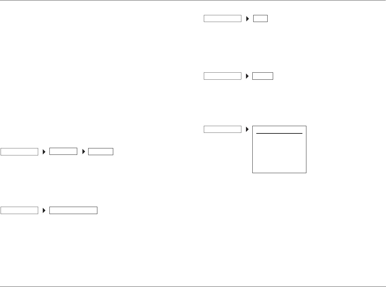
MV-5 Audio & Video Controls
4-3
When the Active PS is set to “USER”, this indicates a factory default
condition.
Note: Once a Preset location has been selected and saved, the factory
default “USER” condition is not longer available for selection.
The Preset locations cannot be selected and are present only to
identify the current state of each location. If the location indicates
“SET” then the preset location has AUTOCAL settings saved to it. If
the location indicates “FACTORY”, then the preset location has not
been used and remains at the default factory settings.
Note: If all three Preset locations indicate “FACTORY”, then the AUTOCAL
procedure has not yet been done, or at the least, the settings have not been
saved.
For more information on the AUTOCAL process, refer to Section 3:
Setup.
HF SHELF +8dB to -8dB in 1dB increments
Located in the EQ ADJUST menu, the HF SHELF control acts as a
high-frequency shelf filter, which boosts or cuts frequencies above
1kHz.
TONE CONTROLS OFF, ON
Actives or deactivates the Bass and Treble Tone Controls. Bass and
Treble controls are only active when the Tone Control is set to ON.
Note: When the incoming audio datastream is stereo analog, the Tone
Controls are OFF, and the Mode Family is set to STEREO, four different
listening modes are available: 7CH STEREO, 5CH STEREO, 2CH STEREO,
and 2CH BYPASS.
BASS +6dB to -6dB in 1dB increments
Controls the amount of low-frequency boost or cut applied to all of
the audio outputs. Bass is an independent setting for each input,
NOT a global setting.
TREBLE +6dB to -6dB in 1dB increments
Controls the amount of high-frequency boost or cut applied to all
of the audio outputs except for the subwoofers. Treble is an
independent setting for each input, NOT a global setting.
AUDIO STATUS
The AUDIO STATUS menu is an information-only menu identifying
the current audio status of the MV-5.
• INPUT identifies the currently selected input.
• NAME identifies the customer-chosen name for the currently
selected input.
• CONNECTOR identifies the current audio connector in use.
• AUDIO identifies what type of audio signal is in use.
• MODE FAMILY identifies the selected mode family.
• MODE identifies the currently selected listening mode.
Note: The Audio line is dashed out if the audio input is analog.
AUDIO CONTROLS EQ ADJUST HF SHELF
AUDIO CONTROLS TONE CONTROLS: OFF
AUDIO CONTROLS BASS
AUDIO CONTROLS TREBLE
AUDIO CONTROLS AUDIO STATUS
INPUT: HD
MODE FAMILY: LOGIC 7
AUDIO: - - -
NAME:
MODE: MUSIC 5.1
CONNECTOR: ANALOG 3
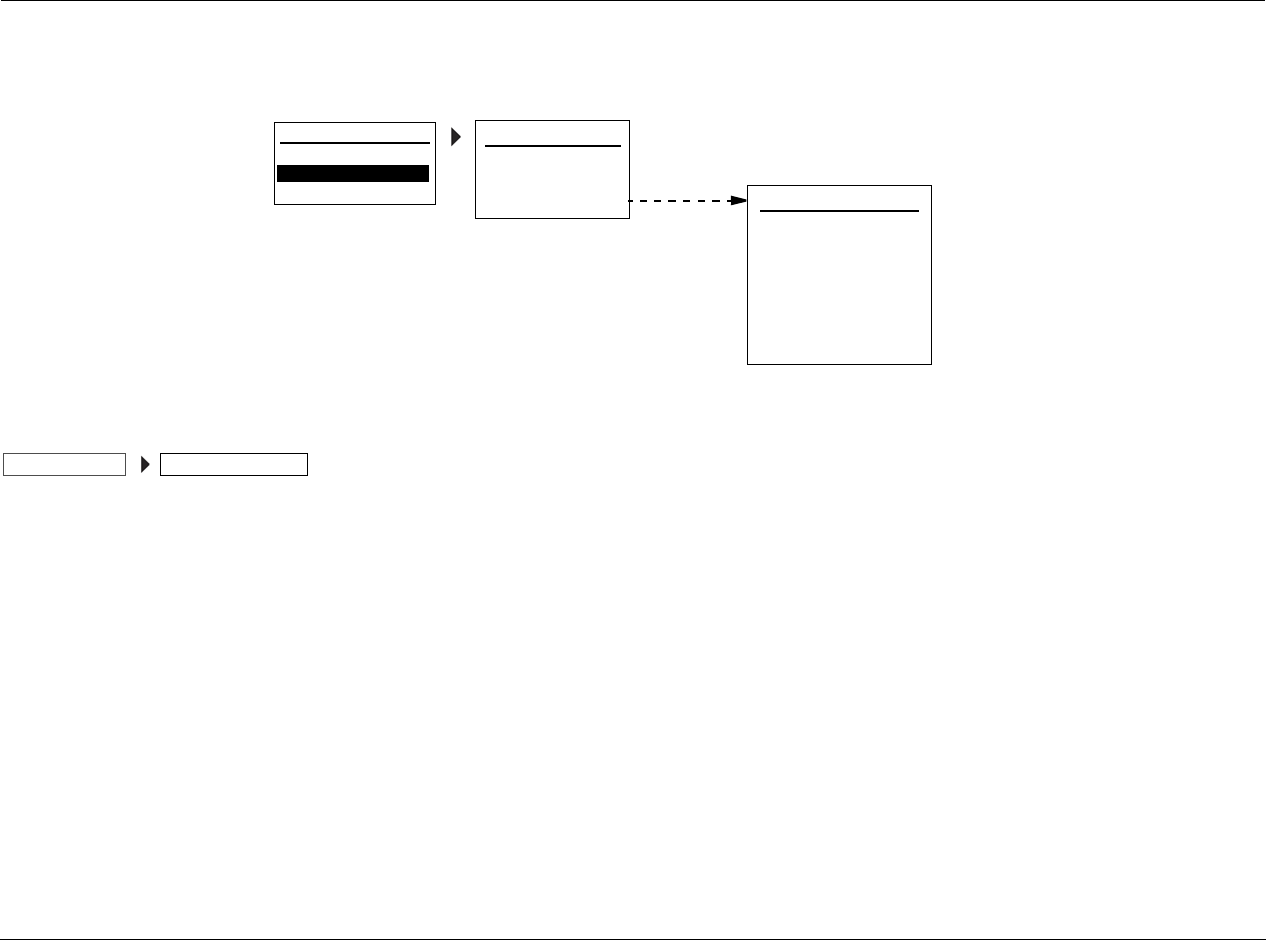
Audio & Video Controls Lexicon
4-4
VIDEO CONTROLS
Selecting VIDEO CONTROLS opens the VIDEO CONTROLS menu, which is used to customize the video connectors.
4:3 IN > 16:9 DISPLAY
Selects the output aspect ratio for the video display when Faroudja
processing is active. In most cases, ORIGINAL provides the best
result, but if the combination of program material, input source
device capabilities, and the adjustments available on the video
display do not provide the desired picture format, the other
parameter options provide additional viewing preferences.
Note: This parameter only affects the video display when the V-PROCESS
parameter in the Input Setup menu is set to FAROUDJA for the currently
selected input.
Available selections include:
• ORIGINAL - Maintains the aspect ratio of the incoming video
signal.
• AUTO - An automatic mode that will apply the processing from
2.35 LB Zoom to a letterbox input or Stretch to a full-screen
4:3 input.
• STRETCH - Applies a non-linear horizontal stretch of a full-
screen 4:3 input to a 16:9 screen. When this option is selected,
objects will appear to be a bit “wider” due to the stretch.
• STRETCH 2 - Applies a stretch to fit full-screen 4:3 images to fill
a 16:9 screen.
• LB ZOOM - Stretches a 4:3 letterbox input vertically so that it
fills a 16:9 screen.
• 2.35 LB ZOOM - Processes a 2.35:1 image that is formatted
with a 4:3 letterbox and vertically stretches it to fill a 16:9
screen, but it will also crop the left and right sides of the image.
• 2.35 LB STRETCH - Processes a 2.35:1 image that is formatted
with a 4:3 letterbox and vertically stretches it to fill a 16:9
screen, with non-linear horizontal processing so that the full
image appears on the screen. When this option is selected,
objects on the far left and rights ides of the screen may appear
to be “narrower” than normal.
4:3 IN>16:9 DISPLAY
VIDEO STATUS
ORIGINAL
VIDEO CONTROLS
INPUT RESOL: - - -
V-PROCESS: FAROUDJA
OUTPUT RESOL: - - -
COMPONENT OUT: 480i
S-VIDEO OUT: OFF
COMPOSITE OUT: OFF
VIDEO STATUS
COPY PROTECTION: OFF
MAIN MENU
AUDIO CONTROLS
VIDEO CONTROLS
SETUP
VIDEO CONTROLS 4:3 IN>16:9 DISPLAY

MV-5 Audio & Video Controls
4-5
VIDEO STATUS
The VIDEO STATUS menu is an information-only menu identifying
the current video status of the MV-5.
• INPUT RESOL identifies the current input resolution setting.
• COPY PROTECTION identifies the current status of the copy
protection mode.
• V-PROCESS identifies the current setting of the video processor.
• OUTPUT RESOL identifies the current output resolution setting
of the HDMI and Component outputs.
Note: The HDMI and component output resolution values are always
the same.
• COMPONENT OUT identifies the currently selected
component output status as described below.
• S-VIDEO OUT identifies the currently selected S-video output
status as described below.
• COMPOSITE OUT identifies the currently selected composite
output status as described below.
The Component, S-Video, and Composite Out parameters all reflect
the interaction between the input type (which is not listed in the
Video Status menu), the copy protection status, the video process
parameter setting, and the current output resolution.
Therefore...
• Component Out will display “OFF” if the component output is
disabled for the current video input and processing
configuration. Otherwise, it will display “Enabled”.
• S-Video Out will display “OFF’ if the S-video output is disabled
for the current video input and processing configuration.
Otherwise, it will display the current output resolution.
• Composite Out will display “OFF’ if the composite output is
disabled for the current video input and processing
configuration. Otherwise, it will display the current output
resolution.
VIDEO CONTROLS
INPUT RESOL: - - -
V-PROCESS: FAROUDJA
OUTPUT RESOL: - - -
COMPONENT OUT: 480i
S-VIDEO OUT: OFF
COMPOSITE OUT: OFF
VIDEO STATUS
COPY PROTECTION: OFF

Audio & Video Controls Lexicon
4-6

5
PC & Dock Controls
PC & Dock Overview ..................................................................5-2
PC Controls.................................................................................5-2
Setting Up to Play..................................................................................... 5-2
Playing PC Media...................................................................................... 5-3
Dock Functionality ......................................................................5-4
Connecting the Dock to the MV-5 ............................................................ 5-4
Selecting the correct iPod insert................................................................ 5-4
Docking the iPod ...................................................................................... 5-5
Dock 2-line Display Characteristics............................................................ 5-5
Controlling the iPod with the MV-5 .......................................................... 5-6
Charging the iPod..................................................................................... 5-7
Removing the iPod ................................................................................... 5-7
Zone 2 iPod Controls ................................................................................ 5-7

PC & Dock Controls Lexicon
5-2
PC & DOCK OVERVIEW
Unlike the other ten inputs of the MV-5 Processor, the PC and Dock
inputs are NOT interchangeable. These two inputs have specific
functionality that is exclusive to these individual inputs.
The PC input is tied to the USB jack on the rear panel and is only for
use with media software on a computer. The PC controls and
features are discussed in later sections of this chapter. The Dock
input is tied to the DOCK connector on the rear panel and is only
for use with iPod players connected to the DOCK input using the
optional D-1 Dock accessory. The Dock controls and features are
discussed in later sections of this chapter.
While both of these inputs have devoted touch screen menu
controls using the remote control, there are NO front panel
controls for use with the DOCK or PC inputs.
Note: The audio controls for the PC and Dock inputs are not user-adjustable
and are tied to specific functions. However the video inputs for these two
locations can be set to any of the available rear panel video inputs and are
as fully customizable as any of the other ten video inputs available.
In addition to these Main Zone differences, the PC and DOCK
inputs also behave differently in Zone 2 operation. Unlike the other
inputs, the PC and DOCK inputs operate independently of both
each other and the other ten inputs, regardless of what is playing in
the Main Zone. Any combination of these two inputs may be
selected in the Main Zone and Zone 2, including the selection of
one input playing simultaneously in both zones. In addition, if one
of these inputs is playing in the Main Zone, you can freely choose
any other Analog input in Zone 2.
PC CONTROLS
The MV-5 is capable of direct connection to a computer for audio
playback. Once connected, playback of audio streams from a
computer are possible through your MV-5 Processor, with all the
power and performance of the high-current amplifier, your own
speakers, and the enhanced multi-channel playback made possible
through the use of Logic 7, Dolby Pro Logic II/IIx, or DTS Neo:6
processing.
SETTING UP TO PLAY
The MV-5 Processor connects to a PC-compatible computer
through the USB jack on the rear panel. Connect one of the
available USB jacks on your computer to the USB jack on the MV-5
rear panel using a cable with a standard USB plug on one side and
a USB “Mini B” plug on the other side. Only the PC input can be
used with computer media players, as the PC input is “hard-wired”
to the USB jack.
Note: The PC Input setup displays Digital Audio as USB, Analog Audio as
NONE, and the Dig/Anlg Auto parameter is dashed out. These three
parameters cannot be changed for the PC Input.
The MV-5 may be used with PC-compatible computers running
Microsoft Windows 2000® with Service Pack 4 or higher installed,
Vista®, Windows XP®, or Windows XP Media Center Edition with
Service Pack 1 or higher installed. In addition, you will need to have
a media player installed on the computer. The MV-5 has been
tested for operation with Windows Media Player® Version 8.0 and
above, but it is also compatible with many other popular players
such as iTunes®, WinAmp®, and Real Player®. Always verify that you
have the latest version of the player installed to ensure the best
compatibility and performance.

MV-5 PC & Dock Controls
5-3
When the connection between a computer and the MV-5 is made
for the first time, or if the USB connection is plugged into a different
USB jack on a computer or hub that has not been previously
connected to the MV-5, you will see a series of pop-up messages
from Windows to indicate that the computer is configuring itself for
the new device. Since the MV-5 provides a number of different
functions, you may see the “Found New Hardware” message up to
four times, one each for “A/V Receiver,” “Compatible Device,”
“Audio Receiver”, and “Human Interface Device.”
CAUTION!
Do NOT power cycle the computer while connected to the
MV-5 with the PC input selected. The computer MUST be
on and connected to the MV-5 rear panel USB jack BEFORE
selecting the PC input on the MV-5. Selecting the PC input
first may cause a burst of loud noise that may be
damaging to the speakers or the listener’s hearing.
PLAYING PC MEDIA
Before selecting the PC input on the MV-5, make certain that
one of the media players listed above has been opened on
the computer and is the “top” or active screen. The remote
control PC input commands will not operate the media player if it is
minimized or “behind” other programs.
You are now ready to begin playing music. The MV-5 remote
control or the computer media player program can be used to
control the play, pause, skip forward, and skip back features of the
media player.
Using the MV-5 remote control:
• Page 4 of the “Lex” touch screen menu provides media player
controls for use with the PC input.
•The PC|| option mimics the Pause/Play control. If the playlist
is not active, pressing this option will start the playlist. If the
playlist is already playing, then pressing this option will pause
it.
•The PC- option mimics the Skip Back control. Pressing this
option will cause the media player to skip back a track in the
playlist.
•The PC+ option mimics the Skip Forward control. Pressing this
option will cause the media player to skip forward a track in the
playlist.
Once playback is started, the audio from a USB source is treated the
same as any other two-channel audio source, and you may apply
any of the appropriate surround processing modes.

PC & Dock Controls Lexicon
5-4
DOCK FUNCTIONALITY
The D-1 Dock optional accessory allows you to enter a new world of
listening enjoyment made possible by combining the increased
storage capacity and playback flexibility of an iPod® (not included)
with the sonic power of your Lexicon receiver. Operation is easy,
you can use your Lexicon remote control or the front panel Tuner
section of the MV-5 to access and control your iPod selections. Just
one simple connection and you’re ready to go!
Note: This functionality is ONLY available if you have purchased the D-1
Dock optional accessory.
CONNECTING THE DOCK TO THE MV-5
Before connecting the Dock, turn your receiver off using either the
main power switch or the Standby button.
With the receiver off, press the button on each side of the
connector at the end of the Dock cable and insert this plug into the
DOCK connector on the receiver’s rear panel. The connector is
keyed to only connect in one way. If you inadvertently try to plug
the connector in the wrong way, do not force it. Simply invert the
connector and try again.
When the DOCK connector is attached to the D-1 Dock accessory
and the current input is DOCK, the MV-5 2-line display indicates
that the input is “Unplugged...”. The status will remain as
“Unplugged” until an iPod is actually docked.
Note: The DOCK Input setup displays Digital Audio as NONE, Analog Audio
as DOCK (or “Unplugged” if there is no iPod connected to the MV-5), and
the Dig/Anlg Auto parameter is dashed out. These three parameters cannot
be changed for the DOCK Input.
When the iPod is initially plugged into the MV-5, the iPod goes to
the top of its music menu. When the iPod is removed, the iPod
menu goes to the root menu.
If the MV-5 is in Standby mode and the iPod is currently playing a
track when it is plugged into the Dock, the track will continue to
play and the 2-line display will show the current track information.
SELECTING THE CORRECT iPOD INSERT
Each iPod model is a slightly different size, making it necessary to
use an insert that matches your specific iPod to the D-1 Dock. The
Dock is shipped with the insert for the color screen and photo
models already installed; if you own one of those models, no further
changes are necessary.
If you own a different iPod, first select the insert that matches your
model. The model identification is printed on the back of each of
the four extra inserts supplied with the Dock.
Note: The iPod Shuffle is not supported by the D-1 Dock option.
Press buttons when inserting or removing the plug.
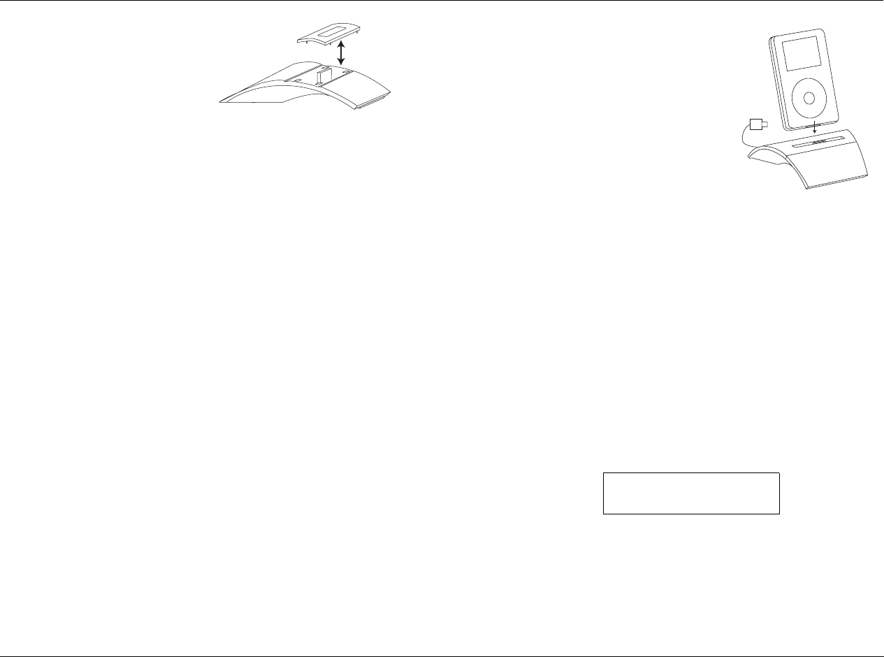
MV-5 PC & Dock Controls
5-5
To remove the factory installed
insert, hold the Dock with one
hand as you grab the edges of
the insert in the Dock with
your other hand, then pull
straight up. Use the following
as a guide to determine which
insert is correct for your iPod model:
• For any iPod with a color screen, including all iPod photo
models, use the insert with “COLOR/PHOTO” on the back.
This insert is already installed in the Dock at the factory.
• For 20GB or 30GB iPod photo models only, remove the insert
marked “COLOR/PHOTO” and attach the two included foam
pads to the rear inside wall in the well of the insert before
replacing it.
• For iPods with a black & white screen and a 10GB, 15GB, or
20GB hard drive, use the insert with “10GB/15GB/20GB” on
the back. (NOTE: The insert only says 10GB/15GB)
• For iPods with a black & white screen and a 30GB or 40GB
hard drive, use the insert with “30GB/40GB” on the back.
• Use the insert with “mini” on the back for all iPod mini models.
• Use the insert with “Universal” on the back for iPod models
that come with a special insert.
Once you have selected the correct insert, place it over the well in
the center of the Dock and gently press it down so that it snaps into
place.
Note: Do not place an iPod in the Dock unless an insert is installed;
otherwise the iPod will not connect properly and damage may occur to the
Dock and/or your iPod that is not covered by the warranty for either
product.
DOCKING THE iPOD
After placing the appropriate insert in the
center well of the Dock and connecting
the Dock to your receiver, dock your iPod
by placing it into the insert, gently
pressing it down until the connectors
mate between the iPod and the Dock.
Note: If you normally keep your iPod in a
protective case, or “skin”, you will need to
remove it before docking your iPod.
When the iPod is plugged into the D-1 DOCK accessory, the iPod
navigation controls are no longer accessible and the iPod screen will
read “Connected and ready to be unplugged“.
DOCK 2-LINE DISPLAY CHARACTERISTICS
When the DOCK input is selected, the 2-line front panel display
changes so that the left side of the display reflects the current iPod
information. Initially, the 2-line display on the MV-5 displays
“Menu” on the left side of the top line. “Playlists” and the number
of playlists available are displayed on the left side of the bottom
line. The ANLG signal type is identified on the top right side and
the current volume setting of the MV-5 is identified on the bottom
right side of the display, as shown:
As the menus on the iPod are scrolled through, the top left side
indicates the menu item selected and the bottom left side indicates
the menu items as they are scrolled through. When a song is
playing, the bottom of the 2-line display identifies the track
counter, the time left on the song, and whether the song is in PLAY
MENU
PLAYLISTS 11
ANLG
-39dB

PC & Dock Controls Lexicon
5-6
or PAUSE mode. The top left side of the display continuously scrolls
through the song, album, and artist information, as shown:
CONTROLLING THE iPOD WITH THE MV-5
There are two ways to control the iPod once it is docked and
connected to the MV-5. The Lexicon MV-5 remote control has a
touch screen menu, page 3 of the “LEX” menu, devoted to
controlling the iPod. In addition, the Tuner section of the MV-5
front panel is a multi-functional panel that also controls the iPod.
The remote control menu buttons and the front panel tuner
buttons provide identical controls.
Note: The following functionality is available only if there is a valid device
connected to the DOCK connector on the rear panel and the DOCK input
has been selected.
Using the MV-5 remote control:
• Page 3 of the “Lex” touch screen menu provides iPod controls
for use with the DOCK input.
• The IPOD- option mimics the Skip Back control. Pressing this
option will cause the iPod to skip back a track in the playlist.
• The IPOD+ option mimics the Skip Forward control. Pressing
this option will cause the iPod to skip forward a track in the
playlist.
•The CLIKoption mimics a counter-clockwise click on the
iPod.
•The CLIKoption mimics a clockwise click on the iPod.
• The MENU option mimics the MENU button on the iPod. The
Menu button backs out of the menu structure, one level at a
time, each time it is pressed.
• The SEL option mimics the SELECT button on the iPod. The
SELECT button acts as a play button at the song level. The
select button drills deeper into the menu structure, one level a
time, each time it’s pressed.
•The|| options mimic the Pause/Play control of the iPod. If the
playlist is not active, pressing either of these options will start
the playlist. If the playlist is already playing, then pressing this
option will pause it.
Using the Front Panel Tuner Controls:
• PRESET- and PRESET+ mimic the and the buttons on the
iPod, which Skip Back and Skip Forward. Pressing these buttons
will cause the iPod to skip back or skip forward one track in the
playlist.
• TUNE- and TUNE+ mimic a counter-clockwise or clockwise click
on the iPod.
• AUTO/MAN mimics the MENU button on the iPod. The MENU
button backs out of the menu structure, one level at a time,
each time it is pressed.
• SAVE mimics the SELECT button on the iPod. The SELECT but-
ton acts as a play button at the song level. The select button
drills deeper into the menu structure, one level at a time, each
time it’s pressed.
• ST/MON and FM/AM both mimic the Play/Pause (|| ) control
of the iPod. If the playlist is not active, pressing this option will
start the playlist. If the playlist is already playing, then pressing
this option will pause it.
Everybody Wants...
0:57 -2:08
ANLG
-32dB

MV-5 PC & Dock Controls
5-7
CHARGING THE iPOD
You may leave your iPod in the Dock even when you are not using
it as a playback source. Whenever the iPod is docked and your
receiver is turned on, the Dock will charge the battery in the iPod.
REMOVING THE iPOD
To remove an iPod from the Dock, grasp the sides of the iPod and
pull it straight up, away from the Dock.
ZONE 2 iPOD CONTROLS
The MV-5 Processor allows the DOCK input, and attached iPod, to
be accessed and output to either the Main Zone or the Zone 2
location. However, for the DOCK inputs, the OSD and front panel
display reflect ONLY the Main Zone activity. Therefore, if the iPod is
accessed in Zone 2, there is no visible indication on the MV-5 that a
change has been made.
To control the iPod in Zone 2 via the remote control:
1. From the Zone 2 menu layer, select the DOCK input (number
pad key 8).
2. Page 1 of the Zone 2 menu layer touch screen provides the
iPod controls.

PC & Dock Controls Lexicon
5-8

6
Troubleshooting & Maintenance
Troubleshooting......................................................................... 6-2
MV-5 Error Messages.................................................................. 6-6
Video Error Messages ................................................................................ 6-6
Autocal Error Messages ............................................................................. 6-7
Video Resolutions Table.............................................................. 6-9
Routine Maintenance ............................................................... 6-11
Restore Factory Default Settings ............................................... 6-11

Troubleshooting & Maintenance Lexicon
6-2
TROUBLESHOOTING
The MV-5 does not power on.
1. Make sure the rear-panel power switch is set to the ON
position.
2. Attempt to power on the MV-5 with the front-panel Standby
button and remote control ON button.
3. Examine the power cord to ensure a good connection between
the rear-panel AC input connector and the wall outlet.
4. Check the electrical circuit and breaker.
The remote control does not work.
1. Eliminate obstructions between the remote control and the
front-panel IR receiver. When the MV-5 is not using the rear
panel IR IN connector, the remote control must be in line of
sight with the front-panel IR receiver for proper operation. The
remote control might also become unreliable if strong sunlight
or fluorescent light is shining on the IR receiver.
2. Make sure the remote control batteries are correctly inserted
with the proper polarity.
3. Replace the remote control batteries. When the batteries are
low on power, the remote control enters a low-voltage
condition that prevents it from operating the MV-5.
4. Make sure that the remote control touchscreen is in the “LEX”,
“Zone 2”, or “Tuner” layers. The remote control is a universal
control designed to operate all of the home theater equipment
in your system. In order to control the MV-5, the remote
control must be in the “LEX”, “Zone 2”, or “Tuner” layers.
5. If using the optional RF-1 RF Receiver, ensure that it is properly
connected to the IR port on the MV-5 rear panel.
The MV-5 is powered on, but there is no audio.
1. Make sure the volume level is audible. Volume level can be
increased with the front-panel volume knob or the remote
control VOL and buttons.
2. Make sure the audio has not been muted. The message “MUTE
ON” is displayed on the on-screen and front-panel displays
when audio has been muted in the Main Zone or in Zone 2. In
addition, the MUTE button on the front panel lights red when
the Main Zone mute is active and green when the Zone 2 mute
is active. If both Zones are muted, the Mute button lights
amber. To deactivate mute, press the MUTE button or adjust
the volume level.
3. Check the INPUT SETUP menu DIGITAL IN and ANALOG IN
parameters to ensure the appropriate audio connector is assigned
to the selected input.
A humming sound is present in the audio.
1. If a cable TV connection is present, disconnect the cable from
the wall outlet. If this eliminates the humming sound, a ground
loop isolation device is required. Contact your dealer or the
cable provider for assistance.
2. Disconnect components one at a time to isolate the problem.
Once the problem is identified, make sure the associated
component is properly grounded and connected to the same
electrical circuit as the MV-5.
RF interference is present in the audio or video.
1. Make sure the MV-5 is not positioned near unshielded TV or FM
antennas, cable TV decoders and other RF-emitting devices.
2. Replace unshielded cables with shielded cables wherever possible.

MV-5 Troubleshooting & Maintenance
6-3
The MV-5 is powered on, but there is no video.
1. Examine the video cables – particularly the S-Video cables –
to ensure a good connection to the associated component.
2. Check the INPUT SETUP menu VIDEO IN parameter to ensure
the appropriate video connector is assigned to the selected
input.
3. Refer to the “Video Error Messages” section found later in this
chapter for more information about specific video-related error
messages.
Video is shifted to the left.
When the MV-5 has both component and HDMI cables connected to
a video monitor with the Faroudja processing active, the Faroudja
processing may cause the video to shift to the left when the
component output is selected, particularly at higher resolution
settings.
To correct the issue, change the Display CONNECTION parameter
from HDMI/DVI to ANALOG, or unplug the HDMI cable.
To change the CONNECTION parameter:
1. Enter the OSD Menu by pressing MENU on the remote control.
2. Use the or cursors to highlight SETUP and then press the
cursor or press the SELECT button to select the menu option.
3. Using the cursors, highlight and select DISPLAY SETUP.
4. Then select CONNECTION. The parameter selection starts to
flash.
5. Use the or cursors to select ANALOG and then press the
cursor to save the selection.
6. Press EXIT to close the OSD menu.
In the Semi Autocal Test, the Far Field Test keeps failing.
1. Ensure that the microphone is placed in the center of the room,
or in your preferred seating location.
2. Ensure that the volume is set to -15dB.
3. In the Speakers Menu, ensure that none of the speakers
connected to the system have a cross-over selection of NONE.
During the Far Field Test, test tones are sent to ALL speaker
locations, regardless of the settings identified in the Speakers
menu. Therefore, every speaker that is plugged in MUST have
a cross-over setting other than NONE for the Far Field test to be
successul. If a cross-over is set to NONE but the speaker is
plugged in, the test will fail because it will “see” a speaker that
is identified as having no cross-over point.
4. Refer to the “Autocal Error Messages” section found later in this
chapter for more information about specific autocal-related
error messages.
Audio sounds distorted when using analog audio inputs.
The likely cause for distorted audio while using the analog audio
inputs is that the input voltage is too high. The MV-5 analog inputs
have a maximum voltage rating of 2 Vrms. Any input voltages
higher than this limit will exhibit audible distortion.
To correct the problem, reduce the analog audio output from the
connected device using the volume or level control. If neither is
available, an intermediate device may be required. Contact your
Lexicon dealer for assistance.

Troubleshooting & Maintenance Lexicon
6-4
The volume won’t go to the specified +10 dB maximum level.
The speaker output level settings may affect the maximum volume
level of the MV-5 Processor. The maximum volume level is +10 dB
minus the maximum output level setting of any speaker. Thus, if
your front L/R output levels are set to +3 dB, the maxium allowable
volume level is +10 dB minus +3 dB, or +7 dB.
The MV-5 is exhibiting erratic behavior.
1. Set the rear-panel power switch to the OFF position. Wait 10
seconds. Then set the rear-panel power switch to the ON
position.
2. Document all user-defined settings on the Installation Worksheet
that begins on page D-2. Then, follow the instructions on the
next page to restore factory default settings.
No audio appears to be output from the MV-5.
• Verify that all rear panel input & output connections are
correct.
• Verify that the Input Setup is set to the correct rear panel input
connections.
• Verify that the incoming datastream is compatible with the
input chosen.
Note: The input connectors marked S/PDIF INPUTS (RCA & TOSLINK
connectors) are not compatible with MP3 sources.
The 2-line OSD display does not appear on the video monitor.
• Verify that the 2-line OSD parameter under the Setup -> Display
Setup -> On-Screen Display menu is not set to OFF.
• Verify the video input source. The 2-line OSD is supported only
at 480i and 576i resolutions when the incoming video source is
digital.
VIDEO IN is set to NONE, but the monitor has a video error, or
is showing a blue screen.
When the VIDEO IN parameter is set to NONE, the MV-5 outputs a
blue screen in 480i resolution. This blue screen cannot be disabled.
If the monitor does not support 480i resolution, the monitor may
display an error message.
Note: This condition can also exist when the VIDEO IN parameter
has been setup, but there is no active incoming signal.
The Subwoofer(s) distorts frequently.
The likely cause for the subwoofer(s) to distort is either an
incorrectly set output level or the subwoofer high-pass filter is set
too low. Verify that the Sub/LFE LPF setting (subwoofer cross-over
point) is set correctly. If correct, try setting the SUB HPF setting to a
higher value to resolve the issue. Refer to Section 3: Setup for more
information.
Both the 2-ch Stereo and 2-ch Stereo Bypass listening modes
pass audio to the subwoofer. What’s the difference?
Both listening modes turn off all surround processing, except for
bass management to the subwoofer, to present pure left- and right-
channel stereo programs. However, the 2-ch Stereo Bypass mode
does not allow any user modification of the audio, such as Tone
Control adjustments.
Note: The 2-ch Stereo Bypass mode is only available when the Tone
Controls are set to OFF.

MV-5 Troubleshooting & Maintenance
6-5
Using the PC input, the remote control commands on page 4 of
the LEX menu, page 3 of the TUNER menu, and page 2 of the
ZONE 2 menu do not work.
1. Make sure that the computer is properly connected to the USB
input of the MV-5 Processor.
2. Make sure that PC is selected as the active input on the RV-5
Receiver.
3. Make sure that the media player being used has been opened
on the computer and is the “top” or active screen. The remote
control PC input commands will not operate the media player if
it is minimized or “behind” other programs.
CAUTION!
Do NOT power cycle the computer while connected to the
MV-5 with the PC input selected. The computer MUST be
on and connected to the MV-5 rear panel USB jack BEFORE
selecting the PC input on the MV-5. Selecting the PC
input first may cause a burst of loud noise that may be
damaging to the speakers or the listener’s hearing.
The iPod does not play or respond to commands from the MV-
5 remote control.
1. Make sure that the Dock is properly connected to a compatible
Lexicon receiver.
2. Make sure that the Dock is selected as the active input on the
RV-5 receiver.
The iPod does not seem to be functioning correctly.
Verify the video input setting of the Dock input in use. If the video
input is set to an HDMI input source, the functionality of the iPod
may be hindered.
The iPod’s front panel display and controls do not operate
when the iPod is docked and the DOCK input is selected as the
MV-5’s active input.
This is normal behavior and does not indicate a problem with the
iPod, the Dock, or the MV-5 Processor. Use the MV-5 remote
control or front panel TUNER buttons to navigate the iPod
functions. Refer to Section 5: Tuner, PC, and Dock Controls, for
further information.
If all else fails...
1. Document all user-defined settings on the Installation
Worksheet that begins on page D-2. Then, refer to the “Restore
Factory Default Settings” section found later in this chapter to
reset the MV-5 to the factory settings.
Note: Unlike other Lexicon products, the MV-5 does NOT have
a configuration tool available at present. If you want to save
your settings before restoring the factory defaults, you must
save them manually. The Installation Worksheets in Appendix
D are provided to assist you.
2. Contact an authorized Lexicon dealer.
3. Contact Lexicon customer service at www.lexicon.com or
781-280-0300.
Note: Visit the knowledgebase at http://www.lexicon.com/kbase for
answers to frequently asked questions and additional troubleshooting
information.

Troubleshooting & Maintenance Lexicon
6-6
MV-5 ERROR MESSAGES
MV-5 error messages are displayed on the OSD when certain error
conditions exist. This section explains what each of these error
messages means and how to fix each problem.
VIDEO ERROR MESSAGES
The following error messages apply specifically to video issues.
VIDEO PROCESS ERROR
This error message will display
when the incoming datastream is
at a higher resolution than the
resolution of the VIDEO OUT
parameter. The MV-5 can
up-sample a lower resolution to a
higher resolution. However it can
not down-sample to a lower
resolution setting.
To correct the problem, right click to return to the VIDEO OUT
Setup parameter and change the VIDEO OUT parameter to AUTO
or to a resolution setting that is higher than that of the incoming
datastream.
VIDEO FORMAT OUTPUT
ERROR
This error message will display
when the MV-5 is connected to an
HDMI video monitor but the
VIDEO OUT parameter is set to a
resolution that is not supported by
the HDMI video monitor.
To correct the problem, right click
to return to the VIDEO OUT Setup
parameter and change the VIDEO
OUT parameter to AUTO or to a
resolution setting that is supported
by the video monitor.
HDCP VIDEO ERROR
This error message will display
when the video monitor is not
HDCP compliant and the
incoming datastream requires
HDCP compliance. Typically, any
HDMI source will require an HDCP
compliant video monitor.
To correct the problem, change
the incoming datastream to a
non-HDCP source or change the
video monitor to one that is HDCP
compliant.
VIDEO PROCESS NOTICE
Video input resolution
can not be higher than
video output resolution
when set to FAROUDJA.
Please adjust settings.
PRESS > TO CONTINUE
VIDEO OUTPUT NOTICE
Video output resolution
not supported by HDMI
monitor. Please select
a different VIDEO OUT
resolution.
PRESS > TO CONTINUE
Display is not
HDCP Capable
HDCP NOTICE

MV-5 Troubleshooting & Maintenance
6-7
CHANGE MONITOR
MESSAGE
This error message flashes on the
2-line front panel and OSD displays
when an analog signal is being sent
to an HDMI monitor.
To correct the problem, change the video monitor setting to an
analog input source.
AUTOCAL ERROR MESSAGES
The following error messages apply specifically to error conditions
that exist during the Autocal or Semi Autocal procedures, or that
pertain to the saved Autocal settings.
MICROPHONE OVERLOAD
ERROR
This error message will display
when the microphone is placed too
close to the speaker grille of the
speaker under test during the Far
Field, Near Field, or Subwoofer
Tests.
CAUTION!
If the microphone is too close to the speaker during test-
ing, damage to the speaker or microphone may result.
To correct the problem, move the microphone further away from
the speaker under test and repeat the test.
FAR FIELD ERROR
This error message will display
when the microphone does not
detect sound from a speaker that
has a crossover setting other than
“NONE” during the Far Field Test.
To correct the problem, check the
microphone position, verify the
speaker cables are connected
properly, verify that the volume
level is correct, and repeat the test.
NEAR FIELD ERROR
This error message will display
when the Near Field test has failed.
Typically, this failure occurs
because the microphone is not in
the proper position or the volume
setting is too low.
To correct the problem, verify that
the microphone is within two feet
of the speaker under test, verify the
speaker cables are connected
properly, verify that the volume
level is correct, and repeat the test.
CHANGE MONITOR TO
ANALOG IN
MICROPHONE OVERLOAD
Verify microphone
position and
lower volume 6dB.
BACK TO SPK/EQ SETUP
REPEAT TEST
FAR FIELD ERROR
FRT-L: NO SIDE-R: NO
CENTER: YES REAR-R: YES
FRT-R: YES REAR-L: YES
SIDE-L: YES
Verify mic position
and spkr connections.
Speakers detected:
If OK, raise volume 5dB.
BACK TO SPK/EQ SETUP
REPEAT TEST
NEAR FIELD AUTOCAL
Verify mic position
and spkr connections.
If OK, raise volume 5dB.
ERROR
BACK TO SPK/EQ SETUP
REPEAT TEST

Troubleshooting & Maintenance Lexicon
6-8
SUBWOOFER CAL ERROR
This error message will display
when the Subwoofer test has
failed. Typically, this failure occurs
because the microphone is not in
the proper position or the volume
setting is too low.
To correct the problem, check the
microphone position, verify the
subwoofer cables are connected
properly, verify that the volume
level is correct, and repeat the test.
Note: If you are using a powered subwoofer, verify that it is
powered on.
CROSS-OVER CHANGE
WARNING
This warning message will display
the first time each speaker or
subwoofer cross-over is manually
changed from the AUTOCAL or
SEMI AUTOCAL settings.
Press the cursor button on the
remote control to clear the
warning message. When cross-over
changes are complete, run the
SEMI AUTOCAL procedure.
SUBWOOFER CAL ERROR
SUBWOOFER 1: NO
SUBWOOFER 2: NO
Verify mic position
and sub connections.
If OK, raise volume 5dB.
Subwoofers detected:
BACK TO SPK/EQ SETUP
REPEAT TEST
CAUTION
Changing these
settings will affect
the autocalibration.
Run SEMI AUTOCAL
after changes are made.
RETURN TO MENU
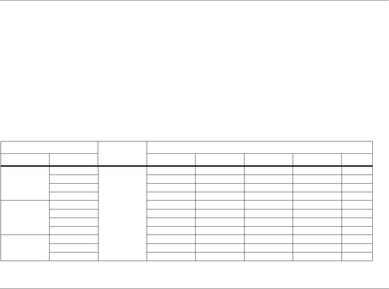
MV-5 Troubleshooting & Maintenance
6-9
VIDEO RESOLUTIONS TABLE
The MV-5 Processor is designed to allow flexibility in the selection of
video output resolutions. However, there are restrictions on what
resolutions can be made available due to incoming signal
limitations.
If you are not getting the expected resolution options for your
video monitor, it is possible that there is an incompability between
the input setup selections and the incoming signal. The table
below describes those formats that are possible, given a specific
input source and input setup conditions.
Notes:
The following notes refer to the “Note” column in the table.
1. If the HDMI video is copy-protected (HDCP), all analog video
output is blocked.
2. If the analog video signal is Macro-vision protected, the
component video output can only be set to 480i or 480p,
regardless of the output resolution setting.
3. The difference between BYPASS and CONVERSION modes is
where the video encoder is used (CONVERSION) or not
(BYPASS) when the S-video or composite video input is selected.
In CONVERSION mode, digital video from the analog input is
provided to the video encoder and the S-video and composite
video outputs are encoded. In BYPASS mode, the analog input
signal goes to the video output directly, with no encoding.
INPUT
Video Mode
OUTPUT
Source Format HDMI Component S-Video Composite Note
HDMI
480i
FAROUDJA ON
480p ~ 1080i 480p ~ 1080i 480i 480i 1
480p 480p ~ 1080i 480p ~ 1080i - - 1
720p 720p ~ 1080i 720p ~ 1080i - - 1
1080i 1080i 1080i - - 1
Component
Analog
480i 480p ~ 1080i 480p ~ 1080i 480i 480i 2
480p 480p ~ 1080i 480p ~ 1080i - - 2
720p 720p ~ 1080i 720p ~ 1080i - - 2
1080i 1080i 1080i - - 2
S-Video,
Composite
Analog
S-480i 480p ~ 1080i 480p ~ 1080i 480i (from S) 480i (from S) 2
C-480i 480p ~ 1080i 480p ~ 1080i 480i (from C) 480i (from C) 2
S&C - 480i 720p ~ 1080i 720p ~ 1080i 480i (from S) 480i (from S) 2
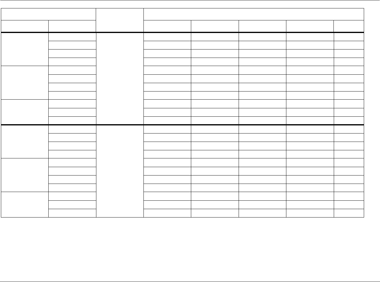
Troubleshooting & Maintenance Lexicon
6-10
HDMI
480i
BYPASS
480i 480i 480i 480i 1
480p 480p 480p - - 1
720p 720p 720p - - 1
1080i 1080i 1080i - - 1
Component
Analog
480i 480i 480i 480i 480i 2
480p 480p 480p - - 2
720p 720p 720p - - 2
1080i 1080i 1080i - - 2
S-Video,
Composite
Analog
S-480i 480i 480i 480i (from S) 480i (from S) 2, 3
C-480i 480i 480i - 480i (from C) 2, 3
S&C - 480i 480i 480i 480i (from S) 480i (from S) 2, 3
HDMI
480i
CONVERSION
480i 480i 480i 480i 1
480p 480p 480p - - 1
720p 720p 720p - - 1
1080i 1080i 1080i - - 1
Component
Analog
480i 480i 480i 480i 480i 2
480p 480p 480p - - 2
720p 720p 720p - - 2
1080i 1080i 1080i - - 2
S-Video,
Composite
Analog
S-480i 480i 480i 480i (from S) 480i (from S) 2, 3
C-480i 480i 480i 480i (from C) 480i (from C) 2, 3
S&C - 480i 480i 480i 480i (from S) 480i (from S) 2, 3
INPUT
Video Mode
OUTPUT
Source Format HDMI Component S-Video Composite Note

MV-5 Troubleshooting & Maintenance
6-11
ROUTINE MAINTENANCE
The bulleted items below describe routine maintenance that should
be performed on a periodic basis.
• Clean the MV-5 exterior surface with a soft, lint-free cloth. Do
not use alcohol, benzene, acetone-based cleaners or strong
commercial cleaners. Do not use a cloth made with steel wool
or metal polish. If the MV-5 is exposed to a dusty environment,
a low-pressure blower can be used to remove dust from its
exterior surface.
• Replace the remote control batteries as needed. The remote
control requires four AAA batteries. When these batteries are
low on power, the remote control enters a low-voltage
condition that prevents it from operating the MV-5. Normal
operation will resume when new batteries are installed.
RESTORE FACTORY DEFAULT SETTINGS
It is possible to reset the MV-5 Processor back to its factory settings.
However, doing do will permanently delete any user-defined or
manually-entered settings, including parameters such as speaker
setup changes, input names, and tuner presets.
Before performing a factory reset, be sure to use the
worksheets in Appendix D to record all of the input and setup
information. The factory reset WILL delete all custom settings
except for the saved EQ Presets.
To restore the factory default settings:
1. Record all parameters and user-defined settings on the
Installation Worksheet that begins on page D-2.
2. Put the MV-5 into Standby.
3. Press and hold the MUTE and ST/MON buttons at the same
time.
After several seconds, the MV-5 will turn on. The front panel display
will state “RESET” and then it will return to the normal display. All
parameters and user-defined values will now reflect the factory
default settings, with the exception of any saved EQ Presets.
Note: The MV-5 does NOT have a configuration tool available. If you
want to save your settings before restoring the factory defaults, you
must record them manually. The Installation Worksheets in Appendix
D are provided to assist you.

Troubleshooting & Maintenance Lexicon
6-12

A
Appendix
Specifications ............................................................................. A-2
Declaration of Conformity.......................................................... A-4
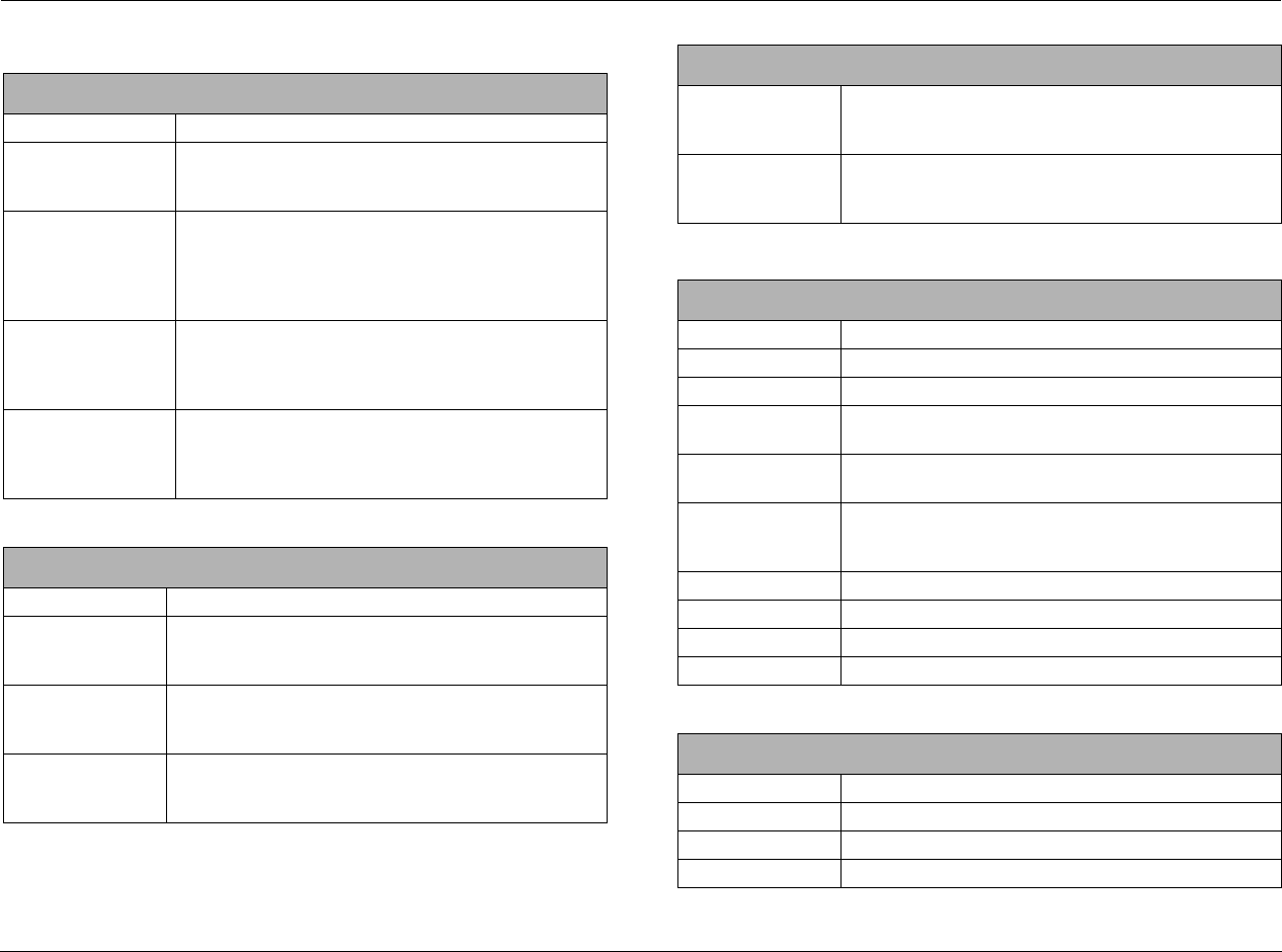
Appendix A Lexicon
A-2
SPECIFICATIONS
Inputs
HDMI (Version 1.1) 2 connectors, HDMI Type A, 19-pin
Analog Video • Three component video, RCA connectors
• Four S-Video connectors
• Four composite video, RCA connectors
Digital Audio • Four S/PDIF coaxial (RCA) and four S/PDIF optical
(Toslink) connectors
• Coaxial & optical input connectors conform to IEC-958,
S/PDIF standards
• One USB mini-B connector
Analog Audio • Eight-channel RCA connectors
• Six Stereo RCA connectors
• One microphone, 3.5mm mono mini plug
• 1 DOCK 30-pin connector (for optional docking station)
Control • One RS-232, 9-pin, D-sub connector
• One IR front panel lens
• One 3.5mm IR IN jack, accepts stereo plug (Tip/Ring/
Sleeve) or mono plug (Tip/Sleeve)
Outputs
HDMI (Version 1.1) One connector, HDMI Type A, 19-pin
Analog Video • One component video, RCA connector
• One S-Video connector
• One composite video, RCA connector
Analog Audio • one 8-channel preamplifier plus additional subwoofer,
RCA connectors
• Zone2 Analog Out: 1 RCA Stereo connector
Control Two triggers - one power on/off & one programmable
3.5mm mono mini plugs
12 VDC, 300mA maximum output draw
HDMI Performance
HDMI Input Video: 480i/p, 576i/p, 720p, or 1080i
Audio: Dolby Digital, DTS, & PCM (32, 44.1, 48, 88.2, 96 kHz,
176.4 kHz, and 192 kHz)
HDMI Output Video: 480i/p, 576i/p, 720p, or 1080i
Audio: Dolby Digital, DTS, & PCM (32, 44.1, 48, 88.2, 96 kHz,
176.4 kHz. and 192 kHz)
S-Video& Composite Video Performance
Compatibility NTSC, PAL, and SECAM
A/D converter 12-bit, 110 MHz
D/A converter 12-bit, 74.25 MHz
Input Level /
Impedance
1V peak-to-peak / 75 Ω
Output Level /
Impedance
1V peak-to-peak / 75 Ω
Frequency Response Composite: 10 Hz to 8 MHz, -3 dB
S-Video: 10 Hz to 8 MHz, -3 dB
Component: 10 Hz to 100 MHz, -3 dB
Signal-to-Noise Ratio >65 dB
Differential Gain <0.2%
Differential Phase <0.5 degrees
Gain +/- 0.15 dB
Component Video Performance
Compatibility 3-channel (Y, Pr, Pb), format-independent
Impedance 75 Ω
Insertion Loss <3 dB
Bandwidth >100 MHz
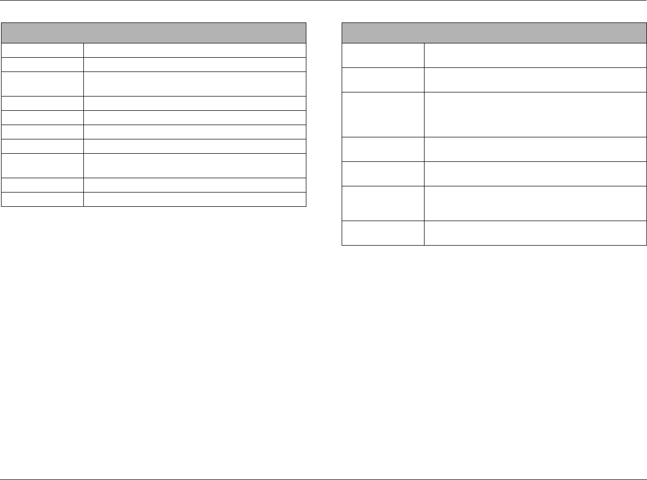
MV-5 Appendix A
A-3
*Depth measurement includes knobs, buttons, and terminal connections.
**For use with optional MRF-100B RF receiver.
Specifications are subject to change without notice.
Main Zone & Zone 2 Audio Performance
A/D conversion 24-bit, 96 kHz, dual-bit ΔΣ
D/A conversion 24-bit, 44.1 to 192 kHz, multi-bit ΔΣ
Input Sensitivity 200 mV for Analog 1 to 6, and 200 mV for 8ch input
max input level: 2 Vrms
Input Impedance 98.5 kΩ for Analog 1 to 6, and 32 kΩ for 8ch input
Frequency Response 10 Hz to 40 kHz, +0, -2 dB
THD + Noise <0.05%, 20 Hz to 20 kHz
Dynamic Range 100 dB typical, 22 kHz bandwidth
Signal-to-Noise Ratio 100 dB typical, 22 kHz bandwidth
min 100 dBA, 103 dBA typical
Output Level 200 mV typical, 6 Vrms maximum
Output Impedance 570 Ω
General
Power Requirements 90-250VAC, 50-60Hz, 50W (Universal line input)
IEC detachable power cords (supplied)
Power Consumption 2W at Power on, idle
46.3W at rated power output (HDMI in/out mode)
Dimensions • Height (with feet): 5.0 inches (127 mm)
• Height (without feet): 4.3 inches (109 mm)
• Width: 16.8 inches (426 mm)
• Depth*: 16.7 inches (423 mm)
Weight • Net Weight: ____ lb (____kg)
• Gross Weight: ____ lb (____kg)
Rack-Mounting Lexicon built rack mount kit not available.
Please seek alternative.
Operating
Environment
• Operating temperature: 0 to 45 C (32 to 113 F)
• Storage temperature: -20 to 60 C (-4 to 140 F)
• Relative humidity: 93% max without condensation
Remote Control Hand-held, back-lit, IR/RF** pre-programmed and learning
remote control (requires 4 AAA batteries – included)

Appendix A Lexicon
A-4
DECLARATION OF CONFORMITY
Application of Council Directive(s):
2004/108/EEC and 73/23/EEC as amended by 93/68/EEC
Standard(s) to Which Conformity is Declared:
EN 55013:2001 + A1:2003
EN 55020:2002 + A1:2003 + A2:2005
EN 61000-3-2:2000 + A2:2005
EN 61000-3-3:1995 + A1:2001
EN 60065:2002
Manufacturer: Harman Specialty Group
3 Oak Park
Bedford, MA 01730-1413 USA
The equipment identified here conforms to the
Directive(s) and Standard(s) specified above.
Type of Equipment: Digital Receiver
Model: Lexicon MV-5
Date: June 2007
Harman Specialty Group
Vice President of Engineering
3 Oak Park
Bedford, MA 01730-1413 USA
Tel: 781-280-0300
Fax: 781-280-0490

B
Appendix
Main Menu: Audio Controls ........................................................B-2
Main Menu: Video Controls ........................................................B-2
Main Menu: Setup ......................................................................B-3
Setup Menu: Display Setup....................................................................... B-4
Setup Menu: Surround Config .................................................................. B-4
Setup Menu: Speaker/EQ Setup ................................................................ B-5
Setup Menu: Input Setup.......................................................................... B-6
Note: All parameter values shown in the following menu trees indicate the
default parameter value if the MV-5 is restored to its factory default
state.
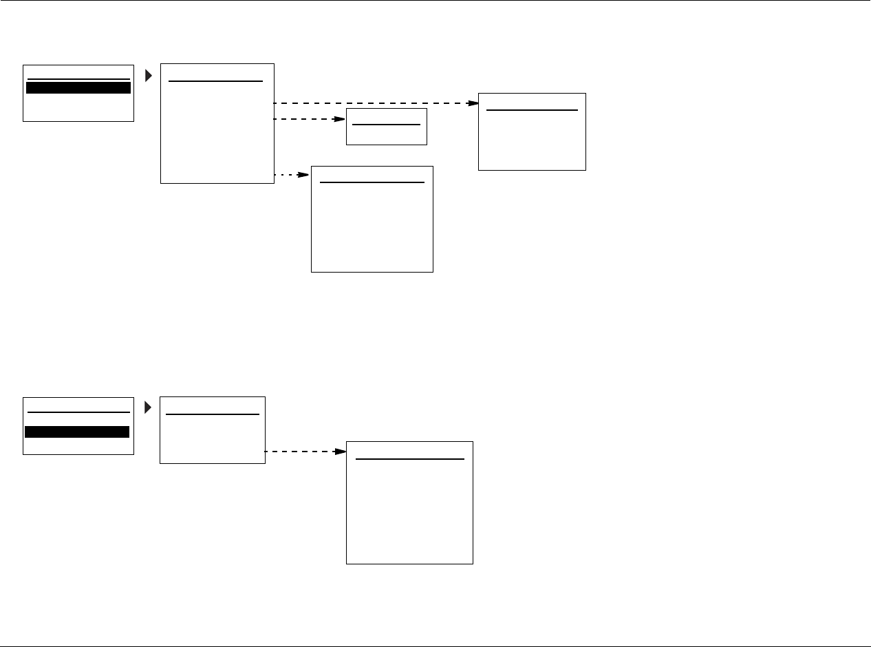
Appendix B Lexicon
B-2
MAIN MENU: AUDIO CONTROLS
MAIN MENU: VIDEO CONTROLS
AUDIO CONTROLS
EQ PRESET
TONE CONTROLS: OFF
BASS: 0dB
TREBLE: 0dB
AUDIO STATUS
EQ PRESET
PRESET 1: FACTORY
ACTIVE PS: USER
PRESET 2: FACTORY
PRESET 3: FACTORY
AUDIO STATUS
INPUT: SAT
MODE FAMILY: LOGIC 7
AUDIO: - - -
NAME:
MODE: MUSIC 5.1
CONNECTOR: ANALOG 3
MAIN MENU
AUDIO CONTROLS
VIDEO CONTROLS
SETUP EQ ADJUST
HF SHELF: 0dB
AUTO EQ: ON
EQ ADJUST
4:3 IN>16:9 DISPLAY
VIDEO STATUS
ORIGINAL
VIDEO CONTROLS
INPUT RESOL: - - -
V-PROCESS: FAROUDJA
OUTPUT RESOL: - - -
COMPONENT OUT: 480i
S-VIDEO OUT: OFF
COMPOSITE OUT: OFF
VIDEO STATUS
COPY PROTECTION: OFF
MAIN MENU
AUDIO CONTROLS
VIDEO CONTROLS
SETUP
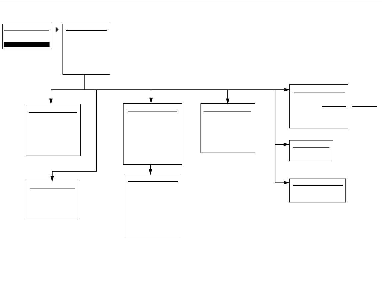
MV-5 Appendix B
B-3
MAIN MENU: SETUP
MAIN MENU
AUDIO CONTROLS
VIDEO CONTROLS
POWER ON SETTINGS
POWER ON VOL: -30dB
DOCK AUTO POWER: ON
INPUT SETUP 1
continued on page B-4
continued on page B-6
DISPLAY SETUP
SPEAKER/EQ SETUP
INPUT SETUP
SURROUND CONFIG
DOLBY CONFIG
MUTE LEVELS
POWER ON SETTINGS
DISPLAY SETUP
DISPLAY TYPE: PLASMA
ASPECT RATIO: 16:9
CONNECTION: HDMI/DVI
HDMI AUDIO OUT: NO
ON-SCREEN DISPLAY
FRONT PANEL DISPLAY
SETUP
continued on page B-4
SETUP
INPUT: HD
NAME: ________
DIG AUDIO: HDMI 1
ANLG AUDIO: NONE
DIG/ANLG AUTO: ON
A/D SAMPLE RATE: 48kHz
MODE FAMILY: LOGIC 7
MODE: FILM 5.1
INPUT SETUP 2
DEFAULT SUR: STANDARD
VIDEO IN: HDMI 1
V-PROCESS: FAROUDJA
VIDEO OUT: AUTO
ADVANCED VIDEO
A/V SYNC DELAY: 0 ms
TRIGGER 2: OFF
ZONE-2 OUT: ANALOG
SURROUND CONFIG
LOGIC 7 DEFAULT: ON
DOLBY MULTI-CHANNEL
DOLBY 2.0
DTS
PCM 44.1/48 kHz
PCM 96kHz
DOLBY CONFIGURATION
MODE: DOLBY PLII MUSIC
CENTER WIDTH: 3
DIMENSION: 0
PANORAMA: OFF
NIGHT: OFF
continued on page B-5
SPEAKER/EQ SETUP
REAR AMP: REAR SPK
MANUAL
SEMI AUTOCAL
FULL AUTOCAL
MUTE LEVELS
MAIN ZONE: -30dB
ZONE-2: -30dB
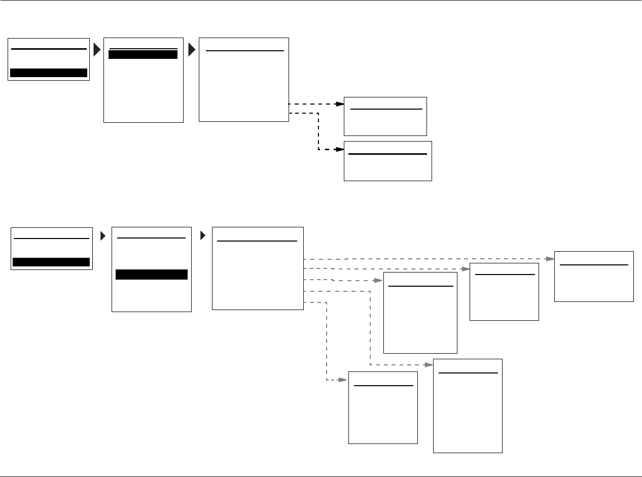
Appendix B Lexicon
B-4
SETUP MENU: DISPLAY SETUP
SETUP MENU: SURROUND CONFIG
ON-SCREEN DISPLAY
2-LINE OSD: 3s
MENU TIME OUT: 30s
FRONT PANEL DISPLAY
BRIGHTNESS: FULL
TIME OUT: NONE
DISPLAY SETUP
DISPLAY TYPE: PLASMA
ASPECT RATIO: 16:9
CONNECTION: HDMI/DVI
HDMI AUDIO OUT: N0
ON-SCREEN DISPLAY
FRONT PANEL DISPLAY
MAIN MENU
AUDIO CONTROLS
VIDEO CONTROLS
DISPLAY SETUP
SPEAKER/EQ SETUP
INPUT SETUP
SURROUND CONFIG
DOLBY CONFIG
MUTE LEVELS
POWER ON SETTINGS
SETUP
SETUP
DOLBY VIRTUAL: OFF
STEREO DOWNMIX: ON
DOLBY MULTI-CHANNEL
LOGIC 7: ON
HALL: ON
5/7 CH STEREO: ON
DTS-ES DISCRETE: ON
LOGIC 7: ON
SURROUND CONFIG
LOGIC 7 DEFAULT: ON
DOLBY MULTI-CHANNEL
DOLBY 2.0
DTS
PCM 44.1/48 kHz
PCM 96kHz
MAIN MENU
AUDIO CONTROLS
VIDEO CONTROLS
DISPLAY SETUP
SPEAKER/EQ SETUP
INPUT SETUP
SURROUND CONFIG
DOLBY CONFIG
MUTE LEVELS
POWER ON SETTINGS
SETUP
SETUP
DOLBY PLII: ON
DOLBY VIRTUAL: OFF
DOLBY 2.0
DOLBY PLIIx: ON
DTS 96/24: ON
DTS-ES MATRIX: ON
DTS
DTS NEO:6: ON
LOGIC 7: ON
STEREO DOWNMIX: ON
DOLBY VIRTUAL: OFF
LOGIC 7: ON
DOLBY PLIIx: ON
PCM 44.1/48 kHz
DOLBY PLII: ON
DTS NEO:6: ON
5/7 CH STEREO: ON
LOGIC 7: ON
DOLBY PLIIx: ON
PCM 96kHz
DOLBY PLII: ON
DTS NEO:6: ON
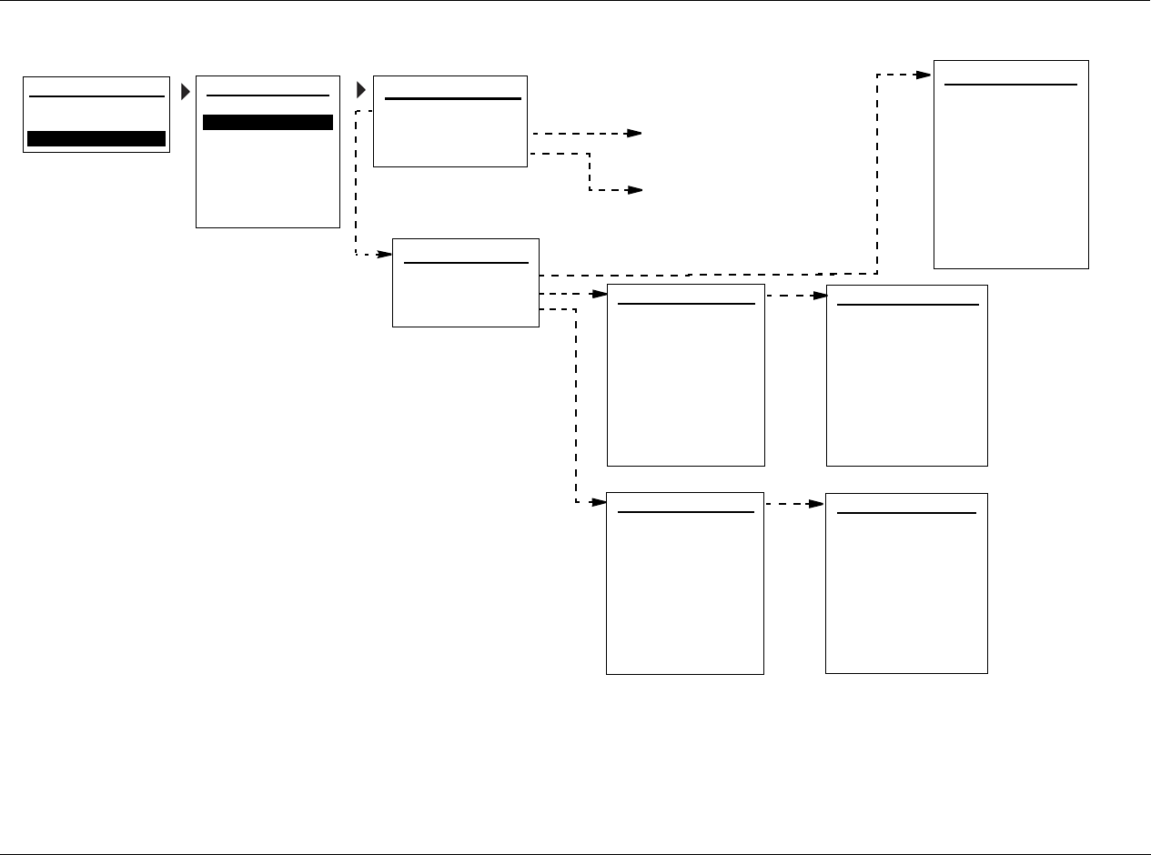
MV-5 Appendix B
B-5
SETUP MENU: SPEAKER/EQ SETUP
MANUAL
SPEAKERS
SPEAKER DISTANCES
OUTPUT LEVELS
SPEAKERS
AUTO SETTINGS: OFF
FRONT L/R: 80Hz
CENTER: 80Hz
SIDE L/R: 80Hz
REAR/Z2 L/R: 80Hz
SUB/LFE LPF: 80Hz
SUBWOOFERS: 1
SUB HPF: 20Hz
SUB MODE: NORMAL
PERFORMS FULL AUTOMATIC
CALIBRATION
PERFORMS SEMI-AUTOMATIC
CALIBRATION
MAIN MENU
AUDIO CONTROLS
VIDEO CONTROLS
DISPLAY SETUP
SPEAKER/EQ SETUP
INPUT SETUP
SURROUND CONFIG
DOLBY CONFIG
MUTE LEVELS
POWER ON SETTINGS
SETUP
SETUP SPEAKER/EQ SETUP
MANUAL
SEMI AUTOCAL
FULL AUTOCAL
SPEAKER DISTANCES 1
AUTO SETTINGS: OFF
UNITS: FEET
FRONT LEFT: 0.0 ft
CENTER: 0.0 ft
FRONT RIGHT: 0.0 ft
SIDE RIGHT: 0.0 ft
REAR RIGHT: 0.0 ft
REAR LEFT: 0.0 ft
SPEAKER DISTANCES 2
SIDE LEFT: 0.0ft
SUBWOOFERS: 0.0 ft
OUTPUT LEVELS 1
AUTO SETTINGS: OFF
INPUT: ALL
TEST TONE: OFF
FRONT LEFT: 0dB
CENTER: 0dB
FRONT RIGHT: 0dB
SIDE RIGHT: 0dB
REAR RIGHT: 0dB
OUTPUT LEVELS 2
RIGHT LEFT: 0dB
SIDE LEFT: 0dB
SUBWOOFER1: 0dB
SUBWOOFER2: 0dB
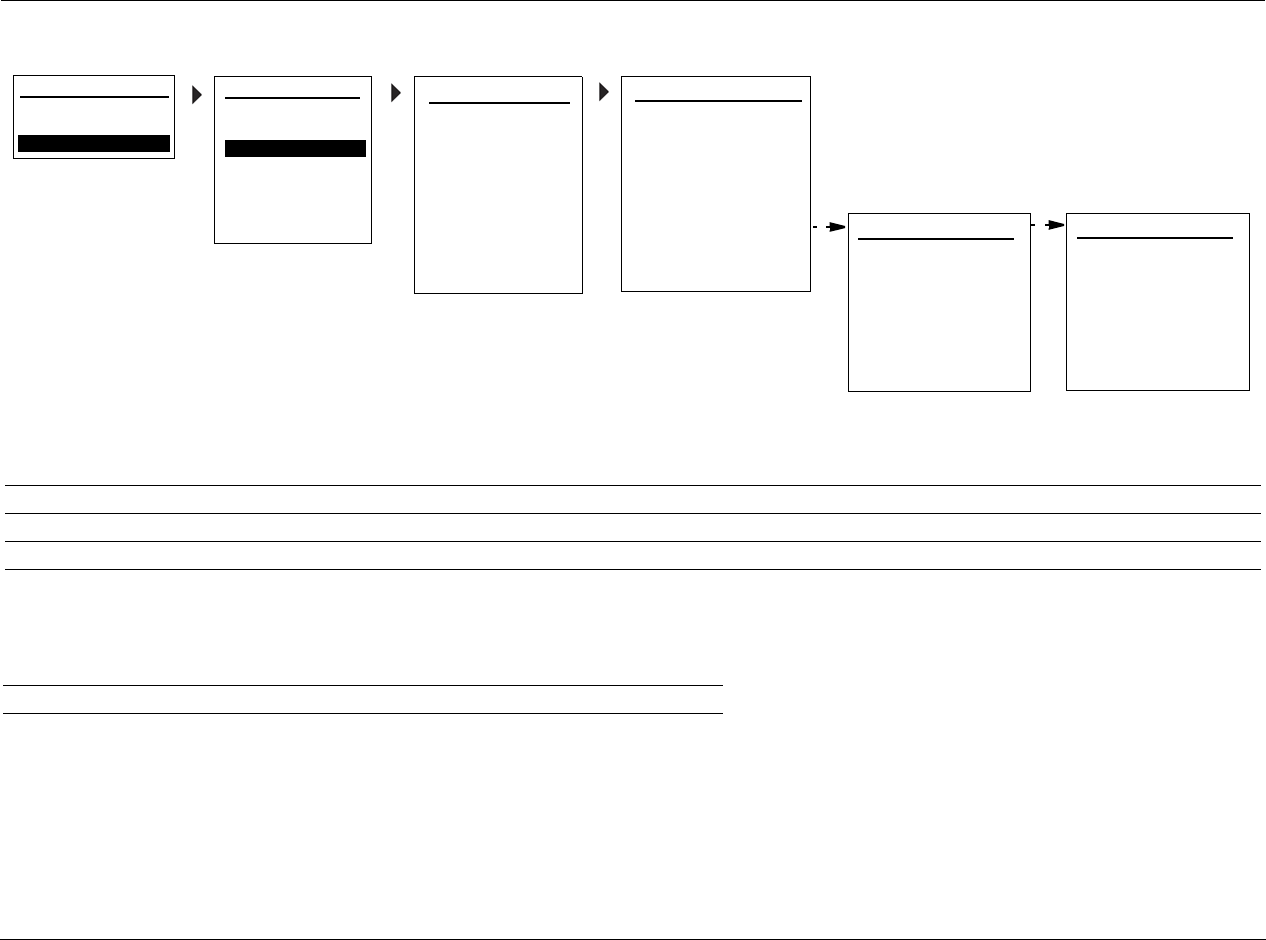
Appendix B Lexicon
B-6
SETUP MENU: INPUT SETUP
*Audio/Video Input Default Settings:
**Mode Input Default Settings for Each Mode Family:
INPUT TYPE: DVD
SHARPNESS: 32
NOISE REDUCTION: OFF
X-COLOR SUPPRESS: ON
DCDi INTERPOL: ON
FILM DETECTION: ON
FILM EDIT DETECT: ON
ADVANCED VIDEO 1
A/D SAMPLE RATE: 48kHz
MODE FAMILY: LOGIC 7
MODE: FILM 5.1**
INPUT SETUP 2
DEFAULT SUR: STANDARD
ADVANCED VIDEO
A/V SYNC DELAY: 0 ms
TRIGGER 2: OFF
ZONE-2 OUT: ANALOG
MAIN MENU
AUDIO CONTROLS
VIDEO CONTROLS
DISPLAY SETUP
SPEAKER/EQ SETUP
INPUT SETUP
SURROUND CONFIG
DOLBY CONFIG
MUTE LEVELS
POWER ON SETTINGS
SETUP
SETUP
FLESHTONE NR: ON
COMPNT ENHANCE: ON
BRIGHTNESS: 100
CONTRAST: 100
COLOR: 100
TEST PAT: OFF
ADVANCED VIDEO 2
INPUT SETUP 1
INPUT: HD*
NAME: ________
DIG AUDIO: HDMI 1*
ANLG AUDIO: NONE*
DIG/ANLG AUTO: ON
VIDEO IN: HDMI 1*
V-PROCESS: FAROUDJA
VIDEO OUT: AUTO
PARAMETER HD DVD GAME SAT CABLE DVR CD DOCK PC TUNER AUX 1 AUX 2
VIDEO IN HDMI 1 Component 1 S-Video 1 Component 2 HDMI 2 Component 3 None None None None S-Video 2 S-Video 3
DIG AUDIO IN HDMI 1 Coaxial 1Optical 1Coaxial 2 HDMI 2 Coaxial 3 Coaxial 4 None USB None Optical 2 Optical 3
ANLG AUDIO IN None None None None None None None Unplugged None None None None
LOGIC 7 (L7) DOLBY DSP STEREO (STER) DTS
FILM 5.1 PLII MOVIE HALL 1 5CH 2-CHANNEL NEO:6 5CH CINEMA

C
Appendix
Remote Control Programming ................................................... C-2
Remote Control Light Button ....................................................................C-2
Transmitting Icon......................................................................................C-2
Setting Up the Remote Control.................................................................C-3
Lock Feature ............................................................................................. C-6
Advanced Customizing Tools .................................................................... C-6
Erasing Commands................................................................................. C-13
Restoring Factory Default Settings...........................................................C-14
Optional RF-1 Receiver ............................................................. C-14
Using the 3-Digit Code Library................................................. C-15
Three-digit Pre-programmed Codes........................................................C-15
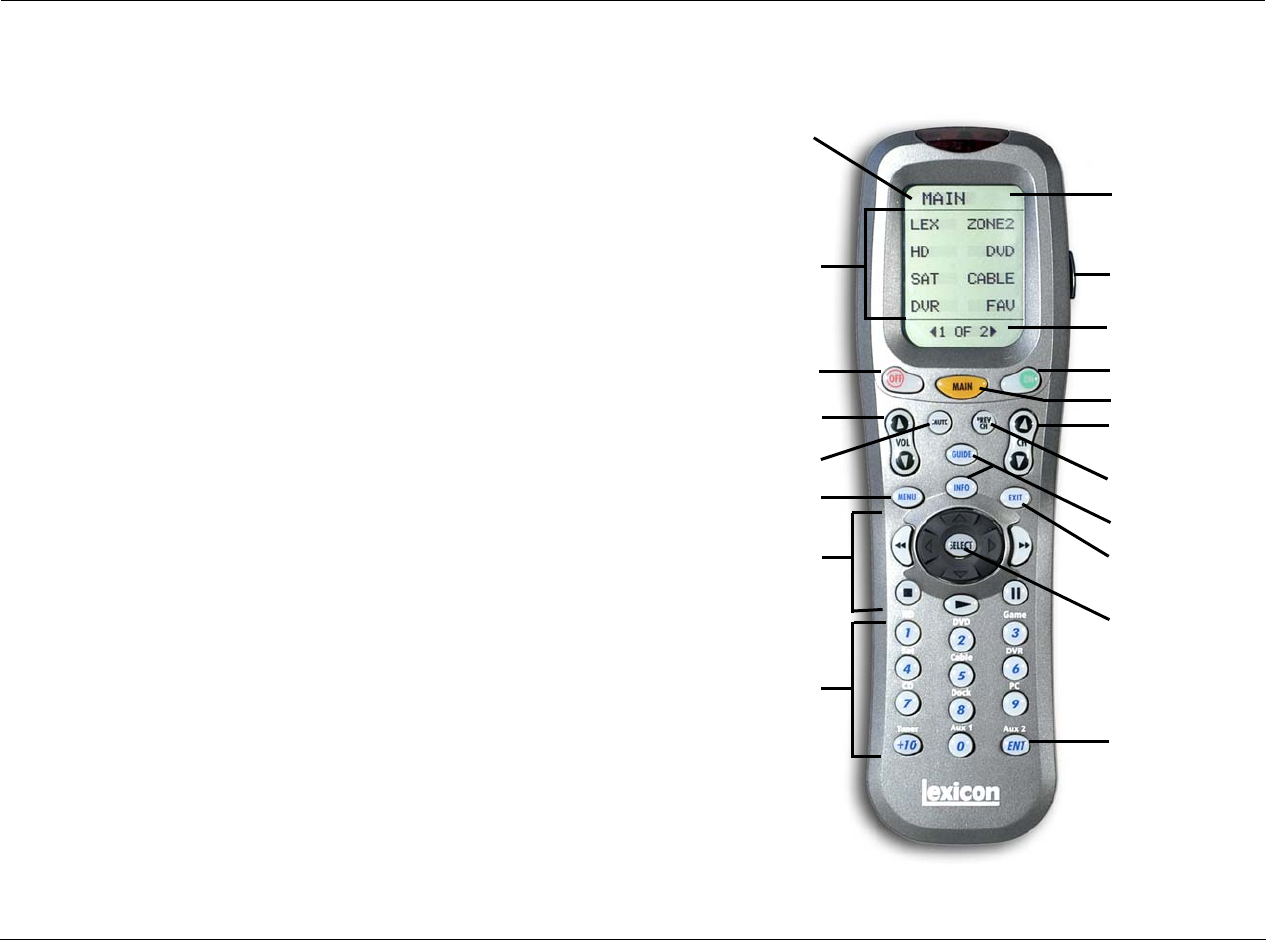
Appendix C Lexicon
C-2
REMOTE CONTROL PROGRAMMING
Designed to provide a new standard in remote control technology, the
MV-5 remote control offers a very powerful and flexible
pre-programmed and learning product. You now have the power to
control your entire home entertainment system with just one remote.
The MV-5 remote control can operate up to 15 home entertainment
and home automation components by using the remote control’s
pre-programmed code library, or by letting the remote control “learn”
from another remote, one button at a time. The MV-5 remote control
has many additional operating features to add convenience and
enjoyment to the operation of any home entertainment system. You
can create your own button labels on the LCD screen; program forty
favorite channel buttons; operate the volume, channel and transport
buttons from one device when you are in another device; and perform
multiple tasks with the press of a single button.
The MV-5 remote control features extensive pre-programmed IR codes
for practically all major audio and video equipment. It can set up and
operate various components by simply entering a 3-digit code.
REMOTE CONTROL LIGHT BUTTON
The remote control is fully back lit, making it easy to use in low
lighting conditions. Press the LIGHT button on the right side of the
remote to back light all of the keypad buttons and the LCD touch
screen. To turn off the back light, press the LIGHT button again or
just stop pushing buttons. Ten seconds after the last button or
touch screen selection, the back light automatically shuts off.
TRANSMITTING ICON
When a command is transmitted by the remote control, a transmit
icon appears in the top right corner of the LCD touch screen. This
indicates that a signal is being sent by the remote control.
ENT (Enter)
LIGHT
POWER ON
SELECT
EXIT
CHANNEL +/-
VOLUME +/-
LCD TOUCH
SCREEN
POWER OFF
MUTE PREV CH
MENU
TRANSPORT
FUNCTIONS
NUMBER
KEYPAD
GUIDE & INFO
MAIN
MENU NAME
MENU PAGES
MENU
OPTIONS

MV-5 Appendix C
C-3
SETTING UP THE REMOTE CONTROL
The MV-5 remote control can be set up so that it controls all of the
components of your home entertainment system, making remote
access simple and efficient. There are two ways to set up the remote
control:
• Pre-programmed Codes - Allows you to set up all of the but-
tons at once, by entering the pre-programmed 3-digit codes of
the component manufacturers.
• Button Learning - Allows you to transfer functions from other
remotes, both old and new, one button at a time.
Of the two methods, the pre-programmed codes method is the
fastest, since all functions are programmed at the same time. However,
it’s possible that a 3-digit code may not be available for your
component. We recommend that you start with the pre-programmed
code method and then perform the button learning method as
necessary.
Pre-Programming Your Remote Control:
Follow the steps below to set up your MV-5 remote control using the
pre-programmed manufacturers’ codes.
The pre-programmed 3-digit codes for each component and
manufacturer can be found at the back of this Appendix. The codes are
listed by Component Category (TV, VCR, DVD, etc) and then by brand
name (Lexicon, Samsung, etc).
1. Find the code listing for the component that you want to set up in
the Pre-Programmed Codes library, found later in this chapter. If
there is more than one code, be sure to note all of them as your
component will only fully respond to one of them, so you may
have to try multiple codes.
2. Turn on the component that you want to setup for remote
control.
3. On the remote control, press and hold the MAIN and ENT (Enter)
buttons at the same time. After about 3 seconds, “SETUP” is
displayed in the Menu name area at the top of the LCD touch
screen. This is the Setup mode of the remote control.
NOTE: You now have 30 seconds to perform the next step while the
remote is in the Setup mode. If a button is not pressed within 30
seconds, the SETUP menu name will revert to MAIN, indicating that
the remote control is no longer in Setup mode. If this occurs, you will
need to repeat this step to re-enter the Setup mode.
4. Touch the P-PRO option to select the Pre-Programmed Method.
The menu name changes to “P-PRO” and the menu options area
now contains seven component options.
Note: While in the Setup mode, the MAIN button acts as an escape
button. Each time the MAIN button is pushed, it will back out of one
menu layer.
5. Select the component that you want to program. If the
component you wish to setup is not on this page, touch the menu
page arrow to select from the components on page 2.
Once a selection is made, the bottom of the screen flashes
“FROM TABLE”.
6. Confirm your component selection by pressing the button again
for the type of component you want to program.
Note: This step is necessary because the selection may not be the
same for Steps 5 and 6. For example, if you are setting up the SAT
option to be a second TV, then the first press in Step 5 would have
been SAT and the second press in Step 6 would then be TV.
7. Point the remote control at the component you want to program
and enter the first of the 3-digit manufacturer’s codes using the
number keypad on the remote.
If the 3-digit code that you entered is the correct one, the
component will turn off. If the component does not turn off,
continue entering code numbers from your list until the
component turns off.
Note: The DOWN and UP buttons on the touch screen can be used to
scroll the code number one digit at a time. If you hold your finger over

Appendix C Lexicon
C-4
the UP or DOWN button, the code number will scroll until your finger
is removed.
8. When the component turns off, press the ON button on the
remote to turn the component back on. Test the volume, channel,
and transport functions to ensure that the component responds
correctly to the remote commands. If any of the buttons do not
work properly, you do not have the right code - enter the next
code option on your list until you find a perfect match for the
component.
Note: If you are unable to find a code that will accurately control your
component, then you’ll need to use the Button Learning procedure,
which follows this procedure, to program the component.
9. Once you’ve found the right code, touch the SAVE option on the
touch screen. The screen will blink “SAVED” two times, indicating
that the code has been successfully saved.
10. Exit the Setup mode by pressing the MAIN button until the touch
screen displays MAIN in the menu heading area. The remote
control is in normal operation mode again.
11. Repeat Steps 1 through 10 to program all other components in
your home theater system. For any components that do not have
a valid 3-digit code, continue to the Button Learning procedure to
program those components.
Recalling Pre-Programmed Setup Code Numbers:
In case you didn’t write down the pre-programmed code numbers
that you used when you set up your Lexicon remote controls, these
3-digit manufacturers’ numbers can be recalled. Perform the
following procedure to recall the pre-programmed 3-digit code for
any component.
1. On the remote control, press and hold the MAIN and ENT (Enter)
buttons at the same time. After about 3 seconds, “SETUP” is
displayed in the Menu name area at the top of the LCD touch
screen. This is the Setup mode of the remote control.
NOTE: You now have 30 seconds to perform the next step while the
remote is in the Setup mode. If a button is not pressed within 30
seconds, the SETUP menu name will revert to MAIN, indicating that
the remote control is no longer in Setup mode. If this occurs, you will
need to repeat this step to re-enter the Setup mode.
2. Touch the RECAL option. The touch screen now shows a four-page
menu that lists each component name and the 3-digit code that
was assigned to it.
3. Write down the code number for each component for future
reference. Appendix D of this manual provides a convenient table
for you to record the 3-digit pre-programmed code numbers.
4. Exit the Setup mode by pressing the MAIN button until the touch
screen displays MAIN in the menu heading area. The remote
control is in normal operation mode again.
Button Learning Procedure For Your Remote Control:
Follow the steps below to set up your MV-5 remote control using the
Button Learning procedure. The MV-5 remote control can “learn”
commands from other remote controls, both old and new, one button
at a time. Follow the steps below to allow your MV-5 remote control to
learn the button commands from other remote controls in your home
theater system.
Note: We recommend that you use this procedure only after you’ve
determined that no 3-digit manufacturers’ codes exist for the component
in question.
1. Line up the MV-5 remote control with the other remote control,
head-to-head, one or two inches apart.

MV-5 Appendix C
C-5
2. On the MV-5 remote control, press and hold the MAIN and ENT
(Enter) buttons at the same time. After about 3 seconds, “SETUP”
is displayed in the Menu name area at the top of the LCD touch
screen. This is the Setup mode of the remote control.
NOTE: You now have 30 seconds to perform the next step while the
remote is in the Setup mode. If a button is not pressed within 30
seconds, the SETUP menu name will revert to MAIN, indicating that
the remote control is no longer in Setup mode. If this occurs, you will
need to repeat this step to re-enter the Setup mode.
3. Touch the LEARN option to select the Button Learning Method.
The menu name changes to “LEARN” and the menu options area
now contains seven component options. The bottom of the
screen flashes “SELECT”.
4. Select the component that you want to program. If the
component you wish to setup is not on this page, touch the menu
page arrow to select from the components on page 2.
Once a selection is made, the menu name changes to the
selected component name.
If you want to teach any command to a component button on
the MV-5 remote control, press the component button when
the menu name says “LEARN”. The menu name will change to
“READY” and the menu page area indicates the button that you
pressed. If you pressed the wrong button, press the MAIN
button to return to the Setup menu where you can start again
(return to Step 3). Once “READY” is displayed, skip ahead to
Step 6.
5. Select the component option that you want to teach the
command to - everything except for the MAIN button and the
menu page arrows can be taught. The menu name will change
to “READY” and the menu page area indicates the button that
you pressed.
6. Press and hold the button on the other remote control that you
want to teach to the MV-5 remote. When the menu name on the
touch screen of the MV-5 remote control changes to “GOOD” or
“FAILD”, release the button.
If “GOOD” is displayed, the bottom of the screen flashes
“SAVED”. The learning procedure is complete and was
successful.
If “FAILD” is displayed, try teaching the same button once
again by repeating Steps 5 & 6.
7. Repeat Steps 4 through 6 to teach the MV-5 remote control any
additional button commands from the component’s remote. To
return to Step 4, press the MAIN button once.
8. When you are done teaching the Lexicon remote control, exit the
Setup mode by pressing the MAIN button until the touch screen
displays MAIN in the menu heading area. The remote control is in
normal operation mode again.
Test all your new commands. If any of them don’t work, try the button
learning procedure again, keeping in mind the following suggestions:
• Move to another room. Plasma TVs, sunlight, halogen, or
quartz lighting can interfere with the learning process.
• Even though the old remote seems to be working fine,
replace the current batteries with fresh alkaline batteries.
• Gradually vary the distance between the remote controls.
Try 1-inch, 2-inches, and so on up to 4-feet.
• Try tapping the button on your old remote instead of just
pressing and holding it during the learning process.
The following list provides additional information regarding the button
learning procedure and how the MV-5 remote control behaves when
taught.
•Learned functions override any existing pre-programmed
functions on the remote control.
• All buttons can be taught except for the menu page arrows,
MAIN button, and LIGHT button.

Appendix C Lexicon
C-6
• Learned functions are automatically erased when a new
function is learned on the same button.
• Learned functions are retained even after a different
pre-programmed 3-digit manufacterer’s code is entered and
saved to the remote.
• To return to an original pre-programmed function, the learned
function must be erased.
LOCK FEATURE
The MV-5 remote control has a locking feature, which prevents
unauthorized use of the remote control. When the locking feature is
active, all operations of the remote control are blocked. This feature
can be used as a “child-lock” to prevent children from having
unmonitored access to the home theater system.
To Activate the Lock Feature:
Press and hold the +10 and ENT (Enter) buttons at the same time. After
3 seconds, the bottom of the touch screen will blink “LOCKED” three
times and then “LOCKED” will remain displayed. The Lock is now
active.
To Return to Normal Operation:
While the remote is in the LOCKED condition, press and hold the +10
and ENT (Enter) buttons at the same time. After 3 seconds, the
“LOCKED” message is replaced by the last used mode is displayed. The
Lock is now deactivated.
ADVANCED CUSTOMIZING TOOLS
Once the basic setup to your remote is complete, you can use the
advanced features to further customize your MV-5 remote control. The
advanced customizing tools include:
• Backlight Options - Customize the backlight feature to suit your
preferences.
• Customize the Touch Screen - Customize the displayed text for
each component menu on the LCD touch screen
• Favorite Channels - Sets up your favorite channel list. Once this
list is set up, up to 40 favorite channels can be selected by the
press of a button. All without needing to remember or type in a
channel number.
• Macros - Enables you to power all of your components ON or
OFF at the same time, with the press of one button.
• Remote Cloning - Allows the user to clone other MV-5/RV-5
remote controls from an already setup remote.
• Punch Throughs - Customized feature controls that allow you
to control similar functions of multiple components at the same
time through the MV-5 remote control.
• Hiding & Adding Pages - Allows the user to customize the
visible pages on the touch screen display.

MV-5 Appendix C
C-7
Backlight Time Out:
The backlight feature lights the touch screen area and illuminates the
buttons whenver the LIGHT button is pressed. The amount of time the
backlight remains on before timing out can be adjusted to your
preferences. Follow the instructions below to change the backlight
time out setting.
1. On the remote control, press and hold the MAIN and ENT (Enter)
buttons at the same time. After about 3 seconds, “SETUP” is
displayed in the Menu name area at the top of the LCD touch
screen. This is the Setup mode of the remote control.
NOTE: You now have 30 seconds to perform the next step while the
remote is in the Setup mode. If a button is not pressed within 30
seconds, the SETUP menu name will revert to MAIN, indicating that
the remote control is no longer in Setup mode. If this occurs, you will
need to repeat this step to re-enter the Setup mode.
2. Touch the menu page arrow to access the second page of the
SETUP menu.
3. Press the LIGHT button to customize the backlight time out
setting. A new screen now displays ON, 10, SAVE, and EXIT. The
bottom of the touch screen says “SECOND” and there’s a flashing
box over the “1” digit. The current setting for the backlight time
out is “10” seconds.
4. Use the number keypad to enter a new time. The setting range is
01 to 99 seconds. To turn the backlight feature off, which saves
battery life, touch the ON option. The ON button changes to OFF
and the time is dashed out.
5. Touch the SAVE option to save the new setting. Touching the EXIT
option will leave the menu without saving any changes.
6. When finished, exit the Setup mode by pressing the MAIN button
until the touch screen displays MAIN in the menu heading area.
The remote control is in normal operation mode again.
Adjusting the Touch Screen Contrast:
You can make the text in the touch screen area darker by pressing the
MAIN and cursor buttons at the same time. To make the text
appear lighter, press the MAIN and cursor buttons at the same time.
Customizing the Touch Screen:
The LCD touch screen component names and commands can be
customized to your preferences. Follow the instructions below to
change the text in a selected touch screen menu.
1. On the remote control, press and hold the MAIN and ENT (Enter)
buttons at the same time. After about 3 seconds, “SETUP” is
displayed in the Menu name area at the top of the LCD touch
screen. This is the Setup mode of the remote control.
NOTE: You now have 30 seconds to perform the next step while the
remote is in the Setup mode. If a button is not pressed within 30
seconds, the SETUP menu name will revert to MAIN, indicating that
the remote control is no longer in Setup mode. If this occurs, you will
need to repeat this step to re-enter the Setup mode.
2. Touch the EDIT option to customize the touch screen option
names. The menu name changes to “EDIT” and the bottom of the
screen flashes “SELECT BUTTON”.
3. Touch the TEXT option. The menu name still reads “EDIT” but
now the component options are displayed.
Once the TEXT option is pressed, the bottom of the screen
flashes “SELECT”.
4. Navigate to the menu page where you want to EDIT the text. You
can edit either the component names or the specific component
controls. The menu name will reflect the actual menu heading,
“EDIT” will no longer be displayed.
5. When the menu to be edited is displayed, touch the PAGE option
until the desired screen is once again displayed.
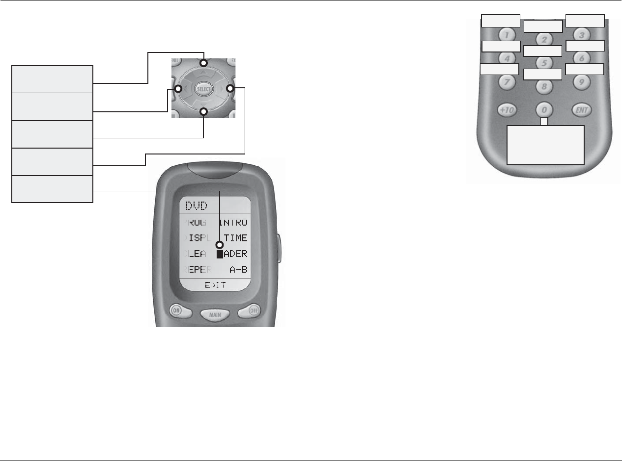
Appendix C Lexicon
C-8
6. Now touch the text that you want to edit. The first letter will start
flashing with a black box.
7. Changing the text requires
the dual use of the number
keypad and the up/down/
left/right cursors. The
number keypad has
specific letters, numbers,
and symbols defined for
each key, as shown.
Pressing the and
cursors will scroll through
the defined characters of
each number keypad
button. Pressing the and
cursors changes the
position of the cursors in
the text being edited.
8. When you are finished editing, touch the text that you just edited.
“SAVED” flashes at the bottom of the display and then “SELECT”
will blink again.
To edit any other menu options in the same menu, touch the
next button when “SELECT” is displayed again. Repeat Steps 6
through 8.
To edit a menu option in a different menu, press the MAIN
button once and then repeat Steps 4 to 8.
9. When finished, exit the Setup mode by pressing the MAIN button
until the touch screen displays MAIN in the menu heading area.
The remote control is in normal operation mode again.
50#523/2
"UTTONDELETESALLTEXT
,%&4#523/2
-OVESBLINKING
CHARACTERLEFT
$/7.#523/2
DELETESTHECURRENTLY
BLINKINGCHARACTER
2)'(4#523/2
-OVESBLINKING
CHARACTERRIGHT
",).+).'
#(!2!#4%2
*+,
$%&
-./
!"# '()
012
345 678 9:
__
?h

MV-5 Appendix C
C-9
Favorite Channel Access:
To access the Favorite Channel listings, press the MAIN button to
display page 1 of the Main menu. Touch the FAV (Favorite Channel)
button on the touch screen. A list of favorite TV & cable stations is now
displayed. Each option can be set to instantly select the channel on
your TV. There are five pages of eight favorite channels for a total of
forty buttons.
Favorite Channel Setup:
Before the Favorite Channels can be selected, they must be setup for
your home theater. Follow the instructions to setup your favorite
channel listing.
1. On the remote control, press and hold the MAIN and ENT (Enter)
buttons at the same time. After about 3 seconds, “SETUP” is
displayed in the Menu name area at the top of the LCD touch
screen. This is the Setup mode of the remote control.
NOTE: You now have 30 seconds to perform the next step while the
remote is in the Setup mode. If a button is not pressed within 30
seconds, the SETUP menu name will revert to MAIN, indicating that
the remote control is no longer in Setup mode. If this occurs, you will
need to repeat this step to re-enter the Setup mode.
2. Touch the FAV option to setup your favorite channels. The menu
name changes to “FAV” and the bottom of the screen flashes
“SELECT”.
3. Navigate through the FAV menus until you find the favorite
channel that you want to setup.
Note: You can customize the name of each favorite channel, if
desired. Refer to the “Customizing the Touch Screen” procedure,
found previously in this chapter.
4. Touch the favorite channel that you want to setup. The menu
name will change to display the channel name that was selected.
The bottom of the touch screen displays “STEP 0”, indicating that
you have not yet entered the channel number.
5. Touch the menu option for the component that you will use to
enter the channel number (typically either TV, SAT, or CABLE).
6. Enter the channel number using the number keypad buttons on
the remote.
Note: Some brands of televisions require an ENT (Enter) command
after the channel numbers are entered.
If a number is repeated when setting the channel, for example
channel 522, it is usually best to set a half second delay in
between the identical numbers by pressing the PAUSE (||)
button. Each press of the PAUSE button increases the delay by
half a second.
7. Press the LIGHT button after you enter the channel number. A new
screen now displays with the options: SAVE, UNDO, and EXIT.
8. To save the channel you just entered, touch the SAVE option. The
UNDO otion allows you to erase the last entry. The EXIT option
erases all entries for this channel.
9. To setup additional favorite channels, repeat Steps 3 through 6.
10. When finished, exit the Setup mode by pressing the MAIN button
until the touch screen displays MAIN in the menu heading area.
The remote control is in normal operation mode again.

Appendix C Lexicon
C-10
Macro Power ON Setup:
Any of the touch screen menu options can be setup as Macro buttons.
Follow the instructions below to setup a macro button that will power
ON several components at once.
1. On the remote control, press and hold the MAIN and ENT (Enter)
buttons at the same time. After about 3 seconds, “SETUP” is
displayed in the Menu name area at the top of the LCD touch
screen. This is the Setup mode of the remote control.
NOTE: You now have 30 seconds to perform the next step while the
remote is in the Setup mode. If a button is not pressed within 30
seconds, the SETUP menu name will revert to MAIN, indicating that
the remote control is no longer in Setup mode. If this occurs, you will
need to repeat this step to re-enter the Setup mode.
2. Touch the MACRO option to setup a macro to power ON several
components at the same time. The menu name changes to
“MACRO” and the bottom of the screen flashes “SELECT”.
3. Touch the ON option. The menu name changes to “ON” and the
bottom of the touch screen flashes “STEP 0”, indicating that no
macro steps have been entered yet.
4. Touch a component option that you want the macro to turn ON.
Use the menu page arrows to navigate to the other menu pages, if
required. The menu name changes to the name of the component
option that you touched and the bottom of the screen now flashes
“STEP 1”.
5. Press the ON button again to confirm the action. The Step
Indicator now displays “STEP 2”.
Note: The Step Indicator is a macro step counter. Every button that is
pressed will increase the Step Indicator by one. But don’t worry about
running out of steps, each macro can store up to 190 steps.
6. Press the MAIN button to return to the Main component listing.
7. Repeat Steps 4 through 6 until all of the components that you
want to power ON at once have been added to the macro.
Note: If desired, you can also program delays into the macro between
the commands, by pressing the PAUSE (||) button. Each press adds
half a second to the delay.
8. When all of the components have been added to the macro, press
the LIGHT button. The menu name changes to “MACRO” as a
new screen is displayed with the options: SAVE, UNDO, and EXIT.
9. To save the macro you just entered, touch the SAVE option. The
UNDO option allows you to erase the last step. The EXIT option
erases all steps for the macro.
10. When finished, exit the Setup mode by pressing the MAIN button
until the touch screen displays MAIN in the menu heading area.
The remote control is in normal operation mode again.
Note: There is no touch screen menu listing for the macro you just
saved. However, when you press the ON button on the remote for one
of the included components, MACRO is displayed in the bottom of the
touch screen area.
Macro Power OFF Setup:
To create a macro which will turn OFF several components at the same
time, just follow the same steps as listed above, but press the OFF
button instead of the ON button.
Macro Using Component Button Setup:
To setup a macro to use a component, in Step 2 of the procedure
above, after pressing MACRO, press the page button twice. The
menu name changes to MAIN. Touch the component option that you
want to set as the macro button. You can navigate to page 2 if
necessary. Now continue in the procedure to Step 3 and follow the rest
of the procedure to completion.
Setting a “Press & Hold” Macro:
Another option for the component button macros is to only send the
macro if the component button is held down. The advantage of this
option is that a normal press of the component button will simply

MV-5 Appendix C
C-11
switch components without triggering the macro. Only holding down
the component button will trigger the macro.
To set the “Press & Hold” macro, enter a delay as the first step of the
macro by pressing the PAUSE (||) button. Each press adds half a second
to the delay. The amount of delay determines how long the user must
hold down the button before the macro is sent.
Cloning other Lexicon MV-5 Remote Controls:
If you happen to own more than one MV-5 remote control, you can
copy and transfer the setup from one remote to the other. Follow the
instructions below to clone your MV-5 remote control.
1. On both the programmed remote control and the remote that
you want to program, press and hold the MAIN and ENT (Enter)
buttons at the same time. After about 3 seconds, “SETUP” is
displayed in the Menu name area at the top of the LCD touch
screen. This is the Setup mode of the remote control.
NOTE: You now have 30 seconds to perform the next step while the
remote is in the Setup mode. If a button is not pressed within 30
seconds, the SETUP menu name will revert to MAIN, indicating that
the remote control is no longer in Setup mode. If this occurs, you will
need to repeat this step to re-enter the Setup mode.
2. Touch the CLONE button on both remotes. The menu name
changes to “CLONE” and the bottom of the screen flashes
“SELECT BUTTON”. A new screen now displays with the options:
SEND, RECV, and EXIT.
Touching the EXIT option will leave the menu without making
any changes or triggering the cloning process.
3. Line up the programmed remote control with the unprogrammed
remote control, head-to-head, one or two inches apart.
4. On the unprogrammed remote, touch the RECV option. The
SEND/RECV options are replaced with “START” and the bottom of
the touch screen flashes “PRESS START”.
5. On the programmed remote, touch the SEND option. The SEND/
RECV options are replaced with “START” and the bottom of the
touch screen flashes “PRESS START”.
6. First on the unprogrammed remote and then on the programmed
remote, touch the START option to begin the cloning process.
Note: Cloning typically takes about 40 seconds. After a successful
cloning is complete, the newly cloned remote will flash “GOOD”.
7. When finished, exit the Setup mode by pressing the MAIN button
until the touch screen displays MAIN in the menu heading area.
The remote control is in normal operation mode again.
Setting System Volume Control & Other Punch Throughs:
The MV-5 remote control provides the option of setting up a total
volume control over all of the components in your home theater
system, even with components that don’t have their own built-in
volume controls, such as TiVo. This is a very powerful feature as, once
its setup, it will save you the constant hassle and inconvenience of
switching between component modes to individually adjust volume
controls. This feature is called a “Punch Through” and is not limited to
strictly volume control. Follow the instructions to set the system
volume control. Then see the note following the instructions to learn
what other punch through features are available.
1. Since a home theater system may use the TV for its sound source,
or a specific component such as a surround sound receiver or
home theater system, first you must identify which component
you want to use for the system sound/volume control.
2. On the remote control, press and hold the MAIN and ENT (Enter)
buttons at the same time. After about 3 seconds, “SETUP” is
displayed in the Menu name area at the top of the LCD touch
screen. This is the Setup mode of the remote control.
NOTE: You now have 30 seconds to perform the next step while the
remote is in the Setup mode. If a button is not pressed within 30
seconds, the SETUP menu name will revert to MAIN, indicating that

Appendix C Lexicon
C-12
the remote control is no longer in Setup mode. If this occurs, you will
need to repeat this step to re-enter the Setup mode.
3. Touch the PUNCH option to setup the system volume control. The
menu name changes to “PUNCH” and the bottom of the screen
flashes “SELECT BUTTON”. A new screen now displays with the
options: VOL, PLAY, CH, and VOD.
4. Touch the VOL (Volume) option. The menu name changes to
“VOL” and the component options are displayed. The VOL option
sets up the group of three buttons - Volume Up, Volume Down,
and Mute - all in one action.
The bottom of the touch screen flashes “PUNCH TO”. Touch
the option for the component that doesn’t have volume control
commands yet (like the DVD). This is the component you are
going to PUNCH TO for the volume and mute commands.
Note: If you want to PUNCH TO the MAIN component, press the
POWER OFF button at this time.
5. The bottom of the display will then flash “PUNCH FROM”. Now
select the MAIN component that has the volume commands that
you want to use (for example, “LEX” for the MV-5 Processor). The
bottom of the touch screen flashes “SAVED”.
6. Repeats Steps 4 & 5 to add all of the components that you’d like
to control through the system volume control.
7. When finished, exit the Setup mode by pressing the MAIN button
until the touch screen displays MAIN in the menu heading area.
The remote control is in normal operation mode again.
The Punch Through feature is NOT limited to volume and can also be
applied to channel selection and other functions. If you find yourself
switching to a particular component frequently to use a group of
controls, consider using Punch Through for another group. The
available punch through features, and the controls that the punch
through operates, are:
• VOL - Volume Up, Volume Down, and Mute
• CH - Channel Up, Channel Down, Previous Channel, and
Channel (0 to 9 Number Keypad) buttons
• PLAY - Play, Stop, Pause, Rewind, and Fast Forward
• VOD - Guide, Menu, Info, Exit, Up, Down, Left, Right, and
Select
To set any of the other punch through features, perform the Steps for
the System Volume control, but in Step 4, touch the desired alternate
control option (CH, PLAY, or VOD).
Hiding and Adding Pages:
Each of the component touch screen menus actually contains five
pages. However, in most cases, only two to four pages are visible in the
factory default settings; the rest of the menu pages are hidden. If you
wish to use the hidden pages, you can ADD them. If you don’t want to
use some of the existing pages, you can HIDE them. Follow the
instructions below to add or hide pages in both the component and
favorite menus.
1. On the remote control, press and hold the MAIN and ENT (Enter)
buttons at the same time. After about 3 seconds, “SETUP” is
displayed in the Menu name area at the top of the LCD touch
screen. This is the Setup mode of the remote control.
NOTE: You now have 30 seconds to perform the next step while the
remote is in the Setup mode. If a button is not pressed within 30
seconds, the SETUP menu name will revert to MAIN, indicating that
the remote control is no longer in Setup mode. If this occurs, you will
need to repeat this step to re-enter the Setup mode.
2. Touch the EDIT option to add and hide touch screen menu pages.
The menu name changes to “EDIT” and the bottom of the screen
flashes “SELECT BUTTON”.
A new screen now displays with the options: TEXT, PAGE, and
EXIT. Touching the EXIT option will leave the menu without
saving any changes.

MV-5 Appendix C
C-13
Note: The TEXT option allows the text of each menu to be changed.
Refer to the “Customizing the Touch Screen” procedure, found earlier
in this chapter, for instructions.
3. Touch the PAGE option. The menu name changes to “PAGE” and
the component options are displayed. The bottom of the touch
screen flashes “SELECT”.
4. Navigate to the menu and page that you want to HIDE or ADD.
When you select a page, the top of the screen indicates whether
you want to “ADD?” or “HIDE?” the displayed page.
5. When you’re ready to change a page’s visibility, to ADD or HIDE it,
press the LIGHT button.
6. Repeat Steps 4 and 5 to ADD or HIDE any menu pages desired on
other components or the favorites pages.
7. When finished, exit the Setup mode by pressing the MAIN button
until the touch screen displays MAIN in the menu heading area.
The remote control is in normal operation mode again.
ERASING COMMANDS
You can erase an individual button with a learned command, a macro,
or a favorite channel. You can erase an ENTIRE component’s learned
command or macro buttons. You can also erase ALL of your learned
commands on ALL components, or all your macros and favorite
channels everywhere.
Note: To erase everything and return the remote control to its factory
default settings, refer to the “Restoring Factory Default Settings”
procedure, which follows this secton.
1. On the remote control, press and hold the MAIN and ENT (Enter)
buttons at the same time. After about 3 seconds, “SETUP” is
displayed in the Menu name area at the top of the LCD touch
screen. This is the Setup mode of the remote control.
NOTE: You now have 30 seconds to perform the next step while the
remote is in the Setup mode. If a button is not pressed within 30
seconds, the SETUP menu name will revert to MAIN, indicating that
the remote control is no longer in Setup mode. If this occurs, you will
need to repeat this step to re-enter the Setup mode.
2. Touch the ERASE option to erase learned buttons, macros, or
favorite channels. The menu name changes to “ERASE” and the
bottom of the screen flashes “SELECT BUTTON”.
A new screen now displays with the options: LEARN, FAV,
MACRO, and EXIT. Touching the EXIT option will leave the
menu without making any changes.
3. Touch either the LEARN, MACRO, or FAV option. A new screen
now displays with the following options:
ALL - Erases ALL of the specified LEARNED, MACRO, or FAV
buttons everywhere in the remote.
DEVICE - Erases all the LEARNED or MACRO buttons in a
SINGLE component. This option is not available for FAV
(Favorite) channels since they are not tied specifically to a
component.
KEY - Erases one button only.
4. If you touch ALL, the remote will prompt you by displaying
“SURE?”. After the SURE prompt is touched, all the buttons will be
erased.
5. If you touch DEVICE, a list of component options are displayed.
Touch the component option that you wish to erase. The bottom
of the screen will flash “ERASE” twice, then “ERASED”.
6. If you touch KEY, you’ll need to navigate to the component that
you want. Touch a menu option to erase it. The bottom of the
screen will flash “ERASE” twice, then “ERASED”.
7. When finished, exit the Setup mode by pressing the MAIN button
until the touch screen displays MAIN in the menu heading area.
The remote control is in normal operation mode again.

Appendix C Lexicon
C-14
RESTORING FACTORY DEFAULT SETTINGS
If you’re afraid you’ve muddled up the settings, accidently overwritten
functions that you wanted, or want a “clean-slate” to start from, the
remote control can be reset to its factory default settings. Follow the
instructions below to restore the factory default settings.
Note: Restoring the Factory Default Settings will ERASE all customized
features, including renamed components, learned buttons, and
macros.
1. On the remote control, press and hold the MAIN and STOP
buttons at the same time. The bottom of the touch screen flashes
“WARNING!”.
NOTE: You now have 3 seconds to perform the next step. If a button
is not pressed within 3 seconds, the RESET heading will revert to
MAIN, indicating that the remote control is no longer in Reset mode. If
this occurs, you will need to repeat this step to re-enter the Reset
mode.
2. After about 10 seconds, “RESET” is displayed in the Menu name
section at the top of the LCD touch screen.
A new screen now displays with the options: ALL PROG and
EXIT. Touching the EXIT option will leave the menu without
making any changes.
3. Touch the ALL option. The remote will prompt you by displaying
“SURE?”. After the SURE prompt is touched, the factory default
settings are restored.
4. When the remote is done restoring the factory default settings, the
menu heading reverts to MAIN. When the touch screen displays
MAIN in the menu heading area, then the remote control is in
normal operation mode again.
OPTIONAL RF-1 RECEIVER
The Lexicon MV-5 remote control has an optional RF-1 Receiver that
may be purchased for use with the MV-5 Processor. This optional
device is plugged into the IR port of the MV-5 rear panel. The RF-1
Receiver provides a boost to the Lexicon remote control that allows
multi-directional RF signals to pass through walls, doors, and floors.
The RF-1 Receiver used in conjunction with the MV-5 Processor allows
you to control components that are completely out-of-sight, up to
100-feet away. Since the RF-1 Receiver picks up multi-directional radio
frequency signals, the MV-5 remote control no longer needs to be
pointed directly at the component to control it. Now you can close
your entertainment center doors, hide your components, and still
control them with ease.
The RF-1 Receiver accessory requires no setup to the Lexicon remote in
order for the feature to work. Every time a command is sent from the
remote, it sends both a standard IR and an RF signal. The RF-1 Receiver
automatically receives the remote’s radio signals and translates them
into the infrared commands that control the components.
Note: The Lexicon remote control radio signals will not control components
directly. You must have the RF-1 Receiver installed to receive the remote’s
radio signals. Components that came with “no pointing” radio remote
controls cannot be operated by the Lexicon remote unless the component
can be switched to standard IR via its internal menus. Some remote
control ceiling fans are radio only and cannot be operated by the Lexicon
remote.

MV-5 Appendix C
C-15
USING THE 3-DIGIT CODE LIBRARY
The following pages contain the code library for the 3-digit
pre-programmed manufacturers’ codes for most home theater
equipment. The code library is divided into categories (TV, VCR, etc).
Each category may include several different types of components.
The categories, and the types of components each category includes,
are:
•TV - TVs, Plasmas, Projectors, and Monitors
• CABLE - Cable TVs and Web TVs
• DVD - DVD Players and TV/DVD combos
• VCR - VCRs and TV/VCR combos
• AUDIO - Amps, Preamps, A/V Receivers, and XM Radios
• SAT - Satellite Receivers
• CD - CD Players and CD Changers
• DVR - TiVo, Replay, and other DVRs
• LDP - Laser Disc Players
• LIGHT - Lighting Systems and Dimmers
•TAPE - Tape Decks
• PHONO - Phonographs
• AUX - Multimedia PCs, Xbox, iPod Controls, and Custom
Installation Products
Within each category, the code numbers are listed in rows by brand
(Lexicon, Samsung, etc). Some brands have more than one 3-digit
code for you to try.
THREE-DIGIT PRE-PROGRAMMED CODES
AUDIO
Manufacturer Codes
ADC 007
ADCOM 082 092 161 225 269 355 356 366
AIWA 018 104 170 188 202 203 211 213
AKAI 138 189
AMC 038 125 126 127 128 258 281 282
AMEND 054
AMX 196
ANGSTROM 142
ANTHEM 335 336 337 338 339
ARCAM 141 418 419
ATLANTIC TECHNOLOGY 342
AUDIO ACCESS 147
AUDIO ALCHEMY 135
AUDIO DESIGN 011 194 221
AUDIO EASE 021 196 207
AUDIO FILE 071
AUDIO MATRIX 167
AUDIO SOURCE 273
AUDIO TECHNICA 134
B & K 096 097
BOSE 070 170 224 347 409 459 460 532
BOSTON ACOUSTICS 447
BRYSTON 023
CAMBRIDGE AUDIO 522
CARVER 006 022 028 029 061 071 077 180 185 201 214 226 284
CASIO 076
CHIRO 140
CINEMA SOUND 034 134
CITATION 148 272
CLARION 026
CLASSE 537
COMPAQ 382
CURTIS MATHES 076
DELPHI 415 515
DENON 002 027 034 037 109 215 229 230 234 259 330 340 341
349 350 400 401 402 444 564

Appendix C Lexicon
C-16
AUDIO
Manufacturer Codes
EAD 466
EIGER 149
ELAN 057 290
ENLIGHTENED AUDIO 099 098
ESCIENT 368 381 451 452 453 454
FANFARE 352
FISHER 047 180 182 214 297
FLEXTRONICS 378
FOSGATE 062 231
FOSGATE AUDIONICS 342
GE 056 260
GOLDSTAR 008
HAFLER 174
HARMAN KARDON 118 121 153 154 227 231 233 254 277 317 318 365
HITACHI 020
IMERGE 371
INKEL 197
INTEGRA 354 438
JAMO 398
JBL 263
JCPENNY 076 216
JEFF ROWLAND 206
JENSEN 058
JVC 114 163 191 240 266 279 291
KENWOOD 005 026 066 145 146 151 180 181 182 190 192 197 199 222
280 374 550
KINERGETICS 140 220
KLH 331
KOSS 216 573
KRELL 072 150 376 384
KYOCERA 007
LEXICON 120 235 236 237 357 358 359 360 361 362 363 364
LINN 124 377
LUXMAN 004 009 052 115 137 139 165
LXI 056 076
MAGNAVOX 086 152 164 208
MARANTZ 006 028 031 040 063 119 185 186 251 265 289 296 492
AUDIO
Manufacturer Codes
MCINTOSH 238 286
MCS 076
MERIDIAN 012 013 100
MITSUBISHI 204 242 243
MONDIAL 042 043 081 112 157 158
MYRYAD 276 293
NAD 113 186 283 478 479
NAKAMICHI 111 172 183 244 245 287
NEC 176
NIRO 343
NILES 403
ONKYO 017 046 064 079 080 090 107 108 187 179 209 270 275 438
OPTIMUS 026 041 138
OUTLAW 342
PANASONIC 032 177 195 219 292 383 516
PARASOUND 129 130 132 261 294 295 333 334
PHAST 196
PHILIPS 063 119 249 250 251
PIONEER 014 033 035 039 044 045 050 069 078 116 159 168 198 480
POLKAUDIO 029 515
PRIMARE 464
PROCEED 144 268
RCA 010 048 067 117 156 288
REALISTIC 019 056 073 075 095
REQUEST 351
REVOX 162
ROTEL 074 083 085
RUSSOUND 379 391 392
SAMSUNG 016 571
SANSUI 040 048 065 110 119 228
SANYO 047 059
SCOTT 019 091
SEARS 076
SHARP 026 094 131 175 181
SHERWOOD 024 030 038 051 055 102 103 105 106 447
SONY 015 018 093 101 160 166 184 218 223 247 248 271 353 369
372 380 417 421
SOUNDESIGN 036

MV-5 Appendix C
C-17
AUDIO
Manufacturer Codes
SOUNDMATTERS 375
SOUNDSTREAM 084 088
SSI 068
SUMO 171
SUNFIRE 344 345 346 494
TAEKWANG 138
TEAC 005 019 049 111 212 217
TECHNICS 122 176 177 178 193 200 219 257 262
THETA DIGITAL 136
TOSHIBA 060 087 198 278
WARDS 180
YAMAHA 026 067 089 169 173 205 232 253 264 274 285 332 373 432
433
ZENITH 143 210
AUDIO-XM Radios & Tuners
BOSE 170 532
DELPHI 415 515
FANFARE 352
KENWOOD 550
POLKAUDIO 515
SONY 380
CABLE/WEB TV
Manufacturer Codes
ABC 003 004 039 042 046 053 103
ADELPHIA 043 074
ADVANCED NEWHOUSE 043
ALTRIO 043
AMERICAST 099
ARCHER 005 007 014
ARMSTRONG 074
AT&T BROADBAND 074
ATLANTIC BROADBAND 043 074
BELL SOUTH 099
BLUE RIDGE 043 074
BRESNAN 074
BRIGHT HOUSE 043 110
BUCKEYE COMM 074
CABLEVISION 043 074 108
CENTURION 092
CENTURY 007
CHARTER 043 074
CITIZEN 007
COGECO 074
COMBANO 080 081
COMCAST 043 074 110
COMSAT 074
COX DIGITAL 043 074
DIGICABLE 101
EAGLE 020 030 040
EASTERN 057 066
ECHOSTAR 106
ELECTRICORD 032
GEMINI 008 054
GENERAL ELECTRIC 072
GENERAL INSTRUMENT 074 103 104
GNC 099

Appendix C Lexicon
C-18
CABLE/WEB TV
Manufacturer Codes
GOLDEN CHANNEL 030
HAMLIN 049 050 055
HITACHI 055 103
INSIGHT 074
JERROLD 002 003 004 008 009 010 069 074 103
MAGNAVOX 010 012 064 079 094 095
MASSILLON 074
MEDIA ONE 107
MEDICOM 074
MEMOREX 052
MITSUBISHI 102
MOTOROLA 074 109 110 111
MOVIE TIME 028 032
MOXI 111
NCTC 074
NSC 015 028 038 071
OAK 031 037 053
PACE 043 074
PANASONIC 044 047
PARAGON 052
PHILIPS 006 012 013 020 085 095
PIONEER 034 043 051 063 076 103 105
PRUCER 059
PULSAR 052
RCA 047
RCN 074
RECOTON 098
REGAL 049 050
REGENCY 057
RODGERS 043
SAMSUNG 030
SCIENTIFIC ATLANTA 003 011 041 042 043 045 046
SEREN 043
CABLE/WEB TV
Manufacturer Codes
SERVICE ELECTRIC 074
SHAW 074
SIGECOM 043
SONY 096 108
SPRUCER 047 078
STARCOM 002 004 008 009
STARGATE 008 030 097 104
SUSQUEHANNA 043 074
TIME WARNER 043 074
TOCOM 039 040 056
TOSHIBA 052
UNITED CABLE 004 053
UNIVERSAL 005 007 014 032 035
VIDEOTRON 043
VIEWSTAR 012 015 018 086 087 088 089
WIDE OPEN WEST 043 099
ZENITH 052 060 093 100

MV-5 Appendix C
C-19
CD
Manufacturer Codes
ADCOM 042 062
AIWA 059 065 088 089 105 122 170 187
AKAI 085 195 202
AMC 231 232
AMEND 118
ARCAM 238
AUDIO ACCESS 119 147
AUDIO EASE 165
AUDIO TECHNICA 046
BSR 037 057
CALIFORNIA AUDIO 008 103
CAPETRONIC 063
CARRERA 057 080
CARVER 041 044 050 086 107 130 134 135 138 139 167 185 203
204
CASIO 111 182
CLARINETTE 182
CREEK 159
CROWN 035
DENON 002 123
EMERSON 042 069 102
FISHER 008 050 134 185
FRABA 111
GENEXXA 010 069 102
GOLDSTAR 080
HAITAI 093
HARMAN KARDON 018 033 047 208
HITACHI 042 175
INKEL 130 143 144
JC PENNEY 014 061 092 141
JENSEN 158
JVC 004 022 136 163 213 214 242 243
KENWOOD 007 023 055 071 072 137 142 185 254
CD
Manufacturer Codes
KOSS 061
KRELL 241
KYOCERA 005
LOTTE 102
LUXMAN 011 028 070 076 249 252
LXI 059
MAGNAVOX 044 107
MARANTZ 027 041 044 051 077 107 209 246
MCINTOSH 212 247
MCS 014 073 092
MEMOREX 010
MISSION 044 107
MITSUBISHI 179
MITSUMI 153
MODULAIRE 182
MONDIAL 147
MYRYAD 155 244
NAD 005 006 067 178
NAKAMICHI 095 217 218 219
NEC 014 062
NIKKO 046
NSM 044 107
ONKYO 030 038 039 168 169
OPTIMUS 010 050 057 058 081 082 083 085 093 195
PANASONIC 008 068 103 172 201 248
PARASOUND 233 240
PHILIPS 041 044 107 246 253
PIONEER 010 020 025 056 174 175 176
PROCEED 239
PROTON 044 107 228
QUASAR 008 103
RADIO SHACK 182
RCA 017 042 150

Appendix C Lexicon
C-20
CD
Manufacturer Codes
REALISTIC 042 050 051 102 181 182 187
ROTEL 044 107 161 178 250
SAE 044 107
SANSUI 044 069 107 125 128 171 190
SANYO 050
SCOTT 069 102
SHARP 026 031 051 066
SHERWOOD 003 019 051 096 112 115 119 166
SIGNATURE 033
SONY 048 081 097 126 133 164 177 225 226
SOUNDESIGN 251
SUMO 155
SYLVANIA 044 107
SYMPHONIC 052 181
TAEKWANG 085 195
TANDY 010
TEAC 015 034 036 051 052 079 101 131 140
TECHNICS 008 060 068 103 172 184 200
TECHWOOD 076
THETA DIGITAL 234 235
TOSHIBA 006 067 091 148 160
VECTOR RESEARCH 080
VICTOR 004 022 114 124
WARDS 033 185
YAMAHA 024 046 054 183 186 245
YORX 182
DVD
Manufacturer Codes
AIWA 146
ALPINE 098
APEX DIGITAL 087 111 112 115 116
ARCAM 122
CAMBRIDGE AUDIO 215
CARY AUDIO DESIGN 174
CLASSE 167
COBY 258
DENON 007 080 173
FUNAI 143
GATEWAY 175
GE 026 027
GO VIDEO 137 218 220 221 222
HARMAN KARDON 084 140
HITACHI 101
ILO 268
INTEGRA 142 180
JVC 012
KENWOOD 151
KISS 179 279
KLH 135
KRELL 104
LEXICON 148
LG 057 074 091
LITEON 264 265
MAGNAVOX 066 096
MALATA 267
MARANTZ 083 095
MERIDIAN 153
MITSUBISHI 017
MYRYAD 102 134
NAD 088 155
NAKAMICHI 103

MV-5 Appendix C
C-21
DVD
Manufacturer Codes
ONKYO 035 076 180
OPPO 266
PANASONIC 021 042 138 139 144 150
PHILIPS 066 083 095 105 166
PIONEER 023 092 099 107 108 131
POLAROID 233 234 237
PRIMARE 193 194
PROCEED 086
PROSCAN 026 027
RCA 026 027
RJTECH 269
ROTEL 204
SAMSUNG 056 070 119 137 159 165 170
SANSUI 154
SANYO 147
SENSORY SCIENCE 222 223
SHARP 094
SONY 033 118 126 145 191
SYLVANIA 143
SYMPHONIC 143
TAG MCLAREN 156
TATUNG 102
TEAC 270
THOMPSON 026 027
THULE 177
TOSHIBA 034 035 130 141 164 188
VENTURER 149
VINC 161
YAMAHA 042 089 166 195 197
ZENITH 057 074 091
DVD
Manufacturer Codes
DVD-TV/DVD Combos
AIWA 146
FUNAI 143
SAMSUNG 165
SYLVANIA 143
SYMPHONIC 143
TOSHIBA 130
DVD-TV/DVD/VCR Combos
MAGNAVOX 143
PANASONIC 144
SYLVANIA 143
TOSHIBA 164
DVD-DVD/VCR Combos
GO VIDEO 137 218
PANASONIC 150
PHILIPS 105 (VCR Functions for VCR, 067)
POLAROID 234
SAMSUNG 137 159
SANSUI 154
SONY 145 191
TOSHIBA 141
ZENITH 091 (VCR Functions for VCR, 171)

Appendix C Lexicon
C-22
DVD
Manufacturer Codes
DVD-DVD Recorders
GATEWAY 175
GO VIDEO 220 221 222
ILO 268
KISS 279
LITEON 265
PANASONIC 139
SENSORY SCIENCE 222
SONY 191
TOSHIBA 188
DVR-PVR/TIVO
Manufacturer Codes
DISH 122
ECHOSTAR 122
HUGHES 108 117
HUMAX 117 118
JVC 122
PHILIPS 090 108 117
RCA 109
REPLAY NETWORKS 075
SONY 104 105
TIVO 090 117 118
TOSHIBA 117
LIGHT
Manufacturer Codes
LITE-TOUCH 208 212
LUTRON 077 158 159
X-10 093 183
LD
Manufacturer Codes
DENON 206 207
FUNAI 120
KENWOOD 013 152
MAGNAVOX 032 121
MARANTZ 211
MITSUBISHI 121
NAD 121
OPTIMUS 013 049
PANASONIC 113
PHILIPS 032
PIONEER 106 117 121
RADIO SHACK 120
RCA 002
REALISTIC 049
RUNCO 127
SANYO 075
SHARP 013 152
SONY 053 110
TECHNICS 113
THETA DIGITAL 032
TOSHIBA 106 152
YAMAHA 043 129
PHONO
Manufacturer Codes
JVC 004
KENWOOD 005
PIONEER 003
YAMAHA 001 002

MV-5 Appendix C
C-23
SAT
Manufacturer Codes
CABLEVISION/VOOM 148
DIRECTV 173
ECHOSTAR/DISH 122 167 168
EXPRESSVU 122
GENERAL ELECTRIC 106 150 151
GENERAL INSTRUMENT 148
GOI 122
HITACHI 139 140
HTS 122
HUGHES 068 108 117 154 161 162 165 166
JVC 122
LG 170
MAGNAVOX 136
MEMOREX 136
MITSUBISHI 068 154
MOTOROLA 148
NEXT LEVEL 148
PANASONIC 142 160
PANSAT 172
PAYSAT 136
PHILIPS 068 108 117 136 152 153 154 156
PROSCAN 106 150 151
RADIO SHACK 148
RCA 106 150 151
SAMSUNG 123 155 163 169 175
SKY 164
SONY 103
STAR CHOICE 148
TOSHIBA 068 127 154 157 158
UNIDEN 136
ZENITH 159
TAPE
Manufacturer Codes
AIWA 015 071 100 114
CARVER 006 008 024 027 036
DENON 105 227 229
FISHER 064
GOLDSTAR 011
HARMAN KARDON 233
JVC 106 116 239 240
KENWOOD 005 013 023 026 064 145 146 181 190
LINN 124
LUXMAN 035 137 139
MAGNAVOX 027
MARANTZ 014 027 056 065 087
MCINTOSH 238
MITSUBISHI 242 243
NAD 029 048
NAKAMICHI 025 244 245
ONKYO 002 012 016 017 018 019 115
OPTIMUS 026 054 055
PANASONIC 007 010 032 088 195
PHILIPS 027 087
PIONEER 003 039 047 050 066 098 222
QUASAR 007 088
SANSUI 027 113 119 224
SHARP 026 057 131 175 181
SHERWOOD 004 028 030 033 034 038
SONY 020 022 052 084 089
TEAC 009 059 212
TECHNICS 007 010 076 088 109 122 193
TOSHIBA 112
VICTOR 106
YAMAHA 021 026 031 040 067

Appendix C Lexicon
C-24
TV
Manufacturer Codes
ADMIRAL 072 081 160 161
ADVENT 247
AKAI 146 197 248
A MARK 112 143
AMPRO 073 157 167 183
AMSTRAD 052
ANAM 043 054 056 080 112 131
AOC 004 058 112 197
APEX DIGITAL 006 310
AUDIOVOX 076 273
BARCO 233
BLAUPUNKT 088
BROKSONIC 238
CAIRN 201
CANDLE 002 003 004 197
CAPEHART 058
CETRONIC 043
CITIZEN 002 003 004 043 101 103 143 197
CLASSIC 043
CONCERTO 004
CONTEC 043 050 051
CORONADO 143
CRAIG 043 054
CROWN 043 143
CURTIS MATHES 004 101 143 197
CXC 043
DAEWOO 004 016 043 044 076 103 114 125 127 143
DAYTRON 004 143
DELL 319 320 321
DREAMVISION 235 345
DWIN 177 257
DYNASTY 043
DYNATECH 062
TV
Manufacturer Codes
EIKI 187
ELECTROHOME 024 076 143 196
EMERSON 004 005 028 043 047 048 050 051 076 096 143 151
153 154 155 197
EPSON 324
ESA 323
FISHER 007 057
FUJITSU 198 246 346
FUNAI 028 043
FUTURETECH 043
GATEWAY 242 268
GE 004 008 009 034 056 073 074 091 130 144 155 157 160
161 165 183 197
GOLDSTAR 004 102 106 112 113 116 119 127 143
HALL MARK 004
HANNSPREE 381
HITACHI 004 009 010 011 012 023 072 075 143 158 163 166
HP 316 327 378
HYUNDAI 337 338
INFINITY 164
INFOCUS 230 330 333
INSIGNIA 350
JBL 164
JCPENNEY 004 008 009 024 030 065 101 143 156 160 197
JENSEN 013
JVC 034 038 070 083 145 199 210 240 241
KEC 043
KENWOOD 070 197
KLOSS 002 059
KMC 143
KTV 043 143 154 197
LG 004 102 106 112 113 116 119 127 143 243 284 363 365
LODGENET 072

MV-5 Appendix C
C-25
TV
Manufacturer Codes
LOEWE 164
LOGIK 072
LUXMAN 004
LXI 007 015 052 081 160 164 166
MAGNAVOX 003 004 022 059 060 061 063 064 094 127 160 164 197
226 239 273
MARANTZ 164 184 197
MATSUI 164
MAXENT 242
MEMOREX 004 007 072
METZ 088
MGA 004 024 028 042 197
MINERVA 088
MITSUBISHI 004 024 028 040 042 109 124 146 191
MTC 004 062 101 197
NAD 015 025
NEC 016 019 024 040 056 130 132 134 197 236 237 262 272
NIKEI 043
NUVISION 351
ONKING 043
ONWA 043
OPTOMA 265 270
OPTONICA 019 081
ORION 096
PANASONIC 034 056 080 092 164 208
PHILCO 003 004 024 056 059 060 063 064 164 197
PHILIPS 003 004 005 038 059 093 127 164 184 197 206 239 259
PIONEER 018 023 025 116 135 190 197 234 335
POLAROID 138 268 328 353 354 356 388
PORTLAND 004 143
PROSCAN 144 160 161 165 167
PROTON 004 058 131 143 171 173 193
QUASAR 034 056 092
TV
Manufacturer Codes
RADIO SHACK 004 019 043 127 143
RCA 004 023 024 056 065 074 144 152 156 160 161 165 197
333
REALISTIC 007 019 043 047
ROCTEC 186
RUNCO 073 157 168 169 178 179 180 181 182 183 340
SAMPO 004 058 197 202
SAMSUNG 004 050 089 101 105 127 143 160 228 229 258
SANYO 007 020 053 057 082 166 187
SCEPTRE 276
SCOTT 004 028 043 048 143
SEARS 004 007 015 028 030 057 082 094 143 160 165 166
SELECO 189 200 205 227
SHARP 004 014 019 022 028 029 081 143 170 175 251
SIEMENS 088
SIGNATURE 072
SIM2 189 200 205 227
SOLE 231 232
SONY 070 085 126 139 147 185 194 213 277 279
SOUNDESIGN 003 004 028 043
SPECTRICON 112
SSS 004 043
SUPRE MACY 002
SVA 328
SYLVANIA 003 044 059 060 063 064 127 160 164 197
SYNTAX OLEVIA 376
TANDY 081
TATUNG 056 062
TECHNICS 034 080
TECHWOOD 004
TEKNIKA 002 003 004 024 028 043 072 101 143
TELEFUNKEN 037 046 086 087
TELERENT 072

Appendix C Lexicon
C-26
TV
Manufacturer Codes
TERA 172
TMK 004
TOSHIBA 007 015 030 040 062 101 138 325
TOTEVISION 143
UNIVERSAL 008 009
VIDEO CONCEPTS 146
VIDIKRON 174 184 188 192 340
VIDTECH 004
VIEWSONIC 242
VIZIO 386 387
WARDS 004 008 009 019 028 034 060 061 063 064 072 074 143
164
WESTING HOUSE 076 280
WINBOOK 339
YAMAHA 004 197
YORK 004
YUPITERU 043
ZENITH 072 073 095 103 157 183 243 284
ZONDA 112
VCR
Manufacturer Codes
AIWA 034 161
AKAI 016 043 046 124 125 142 146
AMPRO 072
ANAM 031
AUDIO DYNAMICS 012 023 039 043
BROOKSONIC 035 037 129
CANON 028 031
CAPEHART 108
CRAIG 003 040 135
CURTIS MATHES 031 041
DAEWOO 005 007 010 065 108 110 111 112 116 117 119
DAYTRON 108
VCR
Manufacturer Codes
DBX 012 023 039 043
DYNATECH 034 053
ELECTROHOME 059
EMERSON 006 017 025 027 029 031 034 035 036 037 046 101 116
129 131 138 153 162
FISHER 003 008 009 010
FUNAI 034
GE 031 063 072 107 109 144 147
GO VIDEO 040 115 132 136 155
GOLDSTAR 012 013 020 101 106 114 123
HARMAN KARDON 012 045
HITACHI 004 013 018 026 034 043 063 137 150 160
INSTANTREPLAY 031
JCL 031
JCPENNY 012 013 015 040 066 101
JENSEN 043
JVC 012 031 043 048 050 055 060 130 150 152 166
KENWOOD 014 034 047 048
LG 012 013 020 101 106 114 123
LLOYD 034
LXI 003 009 017 034 106
MAGIN 040
MAGNAVOX 031 034 041 067 068 156 164
MARANTZ 012 031 067 069 156
MARTA 101
MATSUI 027 030
MEI 031
MEMOREX 003 010 014 031 034 053 072 101 102 134 139
MGA 045 046 059
MINOLTA 013 020
MITSUBISHI 013 020 045 046 049 051 059 061 142 151 168
MTC 034 040
MULTITECH 024 034
NEC 012 023 039 043 048
NORDMENDE 043
OPTONICA 053 054

MV-5 Appendix C
C-27
VCR
Manufacturer Codes
ORION 025
PANASONIC 066 070 074 083 133 140 145 157 163 167
PENTAX 013 020 031 063
PHILCO 031 034 067
PHILIPS 031 034 054 067 071 101 156
PILOT 101
PIONEER 013 021 048
PORTLAND 108
PULSAR 072
QUARTZ 002 014
QUASAR 066 075 145
RADIO SHACK 123
RCA 013 020 034 040 041 107 109 140 144 145 147 158
REALISTIC 003 008 010 014 031 034 040 053 054 101
RICO 058
RUNCO 148
SALORA 014
SAMSUNG 032 040 066 102 104 107 109 112 113 115 120 122 125
SANSUI 022 043 048 135
SANYO 003 007 010 014 102 134
SCOTT 017 037 112 129 131
SEARS 003 008 009 010 013 014 081 101 017 073 112
SHARP 031 054 149 159 165
SHINTOM 024
SIGNATURE 034
SONY 003 031 052 056 057 058 076 077 078 149 154
SOUNDESIGN 034
STS 013
SYLVANIA 031 034 059 067
SYMPHONIC 034
TANDY 010 034
TATUNG 039 043
TEAC 034 039 043
VCR
Manufacturer Codes
TECHNICS 031 070
TEKNIKA 019 031 034 101
THOMAS 034
TMK 006
TOSHIBA 008 013 042 047 059 079 081 082 112 131
TOTEVISION 040 101
UNITECH 040
VECTOR RESEARCH 012
VICTOR 048
VIDEO CONCEPTS 012 034 046 141
VIDEOSONIC 040
WARDS 003 013 017 024 031 034 040 053 054 131
YAMAHA 012 034 039 043
ZENITH 034 048 056 058 072 080 101
VCR-TV/VCR Combos
DAEWOO 005 117
EMERSON 153
FUNAI 034
GOLDSTAR 101 123
HITACHI 034
JCPENNEY 101
LG 101 123
LLOYD 034
MAGNAVOX 034 067
MEMOREX 101
PANASONIC 070 167
PHILIPS 034 067
RADIO SHACK 123
RCA 034
SEARS 101
SONY 057 154
SYLVANIA 067
SYMPHONIC 034
THOMAS 034
ZENITH 034

Appendix C Lexicon
C-28
AUX
Manufacturer Codes
3M 152
AIWA 164
APPLE 401
ARCHER 155
AURORA MULTIMEDIA 220
AUTON 191
BOSE 409
CELADON 221
CRESTRON 213 214 215 216 217 218
DELL 261 262
DMX 156
DRAPER SCREEN 204
DREAMVISION 097
DWIN 080 253
EVERQUEST 206
EXTRON 151
FAROUDJA 184
FUJI 209
GATEWAY 261 262
HAUPPAUGE 294 295
HP 261 262
HUNTERDOUGLAS 219
JERROLD 153
JVC 185
KENSINGTON 406
KENWOOD 185
KEYSPAN 297
MAKITA 186 201
MICROSOFT 107 408
MINDPATH 205
NILES 160 187
NSM 161
PIANO DISC PLUS 085
AUX
Manufacturer Codes
POLKAUDIO 162
RUSSOUND 081
SCIENTIFIC ATLANTA 156 163
SIMA 082
SOLO ELECTRONICS 207
SOMFY 078 079
SONY 164 165 166 261 262
STARCOM 153
TURBOSCAN 167
VELODYNE 203
XANTECH 168 169 170 171 172 188 189
AUX-Media PC Controls
DELL 261 262
GATEWAY 261 262
HAUPPAUGE 294 295
HP 261 262
KEYSPAN 297
SONY 261 262
TOSHIBA 261 262
WINBOOK 261 262
AUX-XBox Controls
MICROSOFT/XBOX 107 408
AUX-iPod Controls
APPLE/iPod 401
BOSE 409
KENSINGTON 406

D
Appendix
Installation Worksheet .............................................................. D-2
3-Digit Pre-programmed Codes Worksheet ................................ D-6
Appendix D Lexicon
D-2
INSTALLATION WORKSHEET
INPUT SETUP HD DVD GAME SAT CABLE DVR CD DOCK PC TUNER AUX1 AUX2
NAME
VIDEO IN
V-PROCESS
VIDEO OUT
HDMI LINK
DIG AUDIO NONE USB NONE
ANLG AUDIO DOCK NONE TUNER
DIG/ANLG AUTO N/A N/A N/A
MODE FAMILY**
MODE**
DEFAULT SUR**
A/D SAMPLE RATE
A/V SYNC DELAY
TRIGGER 2
ZONE2 OUT**
ADVANCED VIDEO
INPUT TYPE
SHARPNESS
NOISE REDUCTION
X-COLOR SUPPRESS
DCDi INTERPOL
FILM DETECTION
FILM EDIT DETECTION
FLESHTONE NR
MV-5 Appendix D
D-3
INPUT SETUP HD DVD GAME SAT CABLE DVR CD DOCK PC TUNER AUX1 AUX2
ADVANCED VIDEO (CONTINUED)
COMPNT ENHANCE
BRIGHTNESS
CONTRAST
COLOR
TEST PAT
SPEAKER SETUP
REAR AMP**: ____
AUTO
SETTING
**
FRONT
LEFT CENTER FRONT
RIGHT
SIDE
LEFT
SIDE
RIGHT
REAR
LEFT
REAR
RIGHT
SUB/
LFE LPF
SUB 1
SUB/
LFE HPF
SUB 2
CROSS-OVER POINTS**
DISTANCES (UNITS: ___)**
OUTPUT LEVELS
“ALL” INPUT**
HD INPUT
DVD INPUT
GAME INPUT
SAT INPUT
CABLE INPUT
DVR INPUT
CD INPUT
DOCK INPUT
PC INPUT
TUNER INPUT
AUX 1 INPUT
AUX 2 INPUT
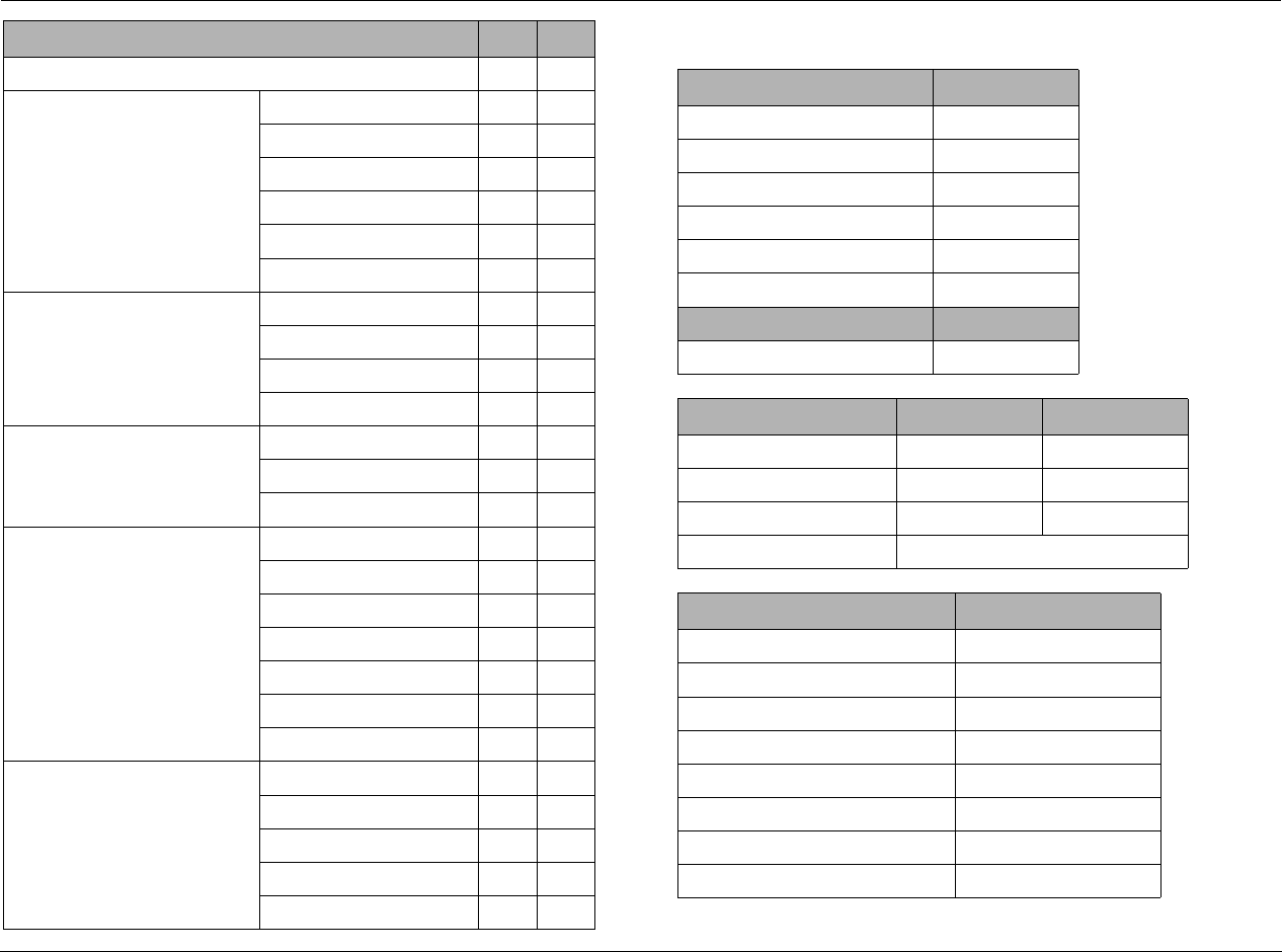
Appendix D Lexicon
D-4
SURROUND CONFIGURATION NO YES
LOGIC 7 DEFAULT**
DTS** DTS 96/24
DTS + NEO:6
DTS-ES MATRIX
DTS-ES DISCRETE
LOGIC 7
STEREO DOWNMIX
DOLBY 2.0** DOLBY PLII
DOLBY PLIIx
DOLBY VIRTUAL
LOGIC 7
DOLBY MULTI-CHANNEL** DOLBY VIRTUAL
LOGIC 7
STEREO DOWNMIX
PCM 44.1/48 kHz** LOGIC 7
DOLBY PLII
DOLBY PLIIx
DOLBY VIRTUAL
DTS NEO:6
HALL
5/7 CH STEREO
PCM 96 kHz** LOGIC 7
DOLBY PLII
DOLBY PLIIx
DTS NEO:6
5/7 CH STEREO
AUDIO CONTROLS SETTING
AUTO EQ**
ACTIVE EQ PRESET**
EQ ADJUST/HF SHELF**
TONE CONTROLS
BASS
TREBLE
VIDEO CONTROLS
4:3 IN >16:9 DISPLAY**
DOLBY CONFIG PLII** PLIIx**
CENTER WIDTH
DIMENSION
PANORAMA
NIGHT
DISPLAY SETUP** SETTING
DISPLAY TYPE
ASPECT RATIO
CONNECTION
HDMI AUDIO OUT
OSD: 2-LINE OSD
OSD: MENU TIME OUT
F/P DISPLAY: BRIGHTNESS
F/P DISPLAY: TIME OUT
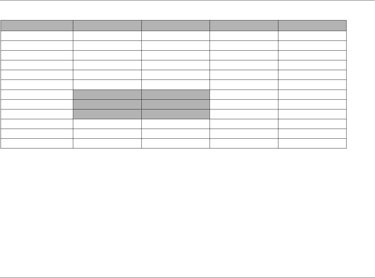
MV-5 Appendix D
D-5
R/P CONNECTIONS ANALOG AUDIO DIGITAL AUDIO ANALOG VIDEO DIGITAL VIDEO
HD INPUT
DVD INPUT
GAME INPUT
SAT INPUT
CABLE INPUT
DVR INPUT
CD INPUT DOCK NONE
DOCK INPUT NONE USB
PC INPUT TUNER NONE
TUNER INPUT
AUX 1 INPUT
AUX 2 INPUT
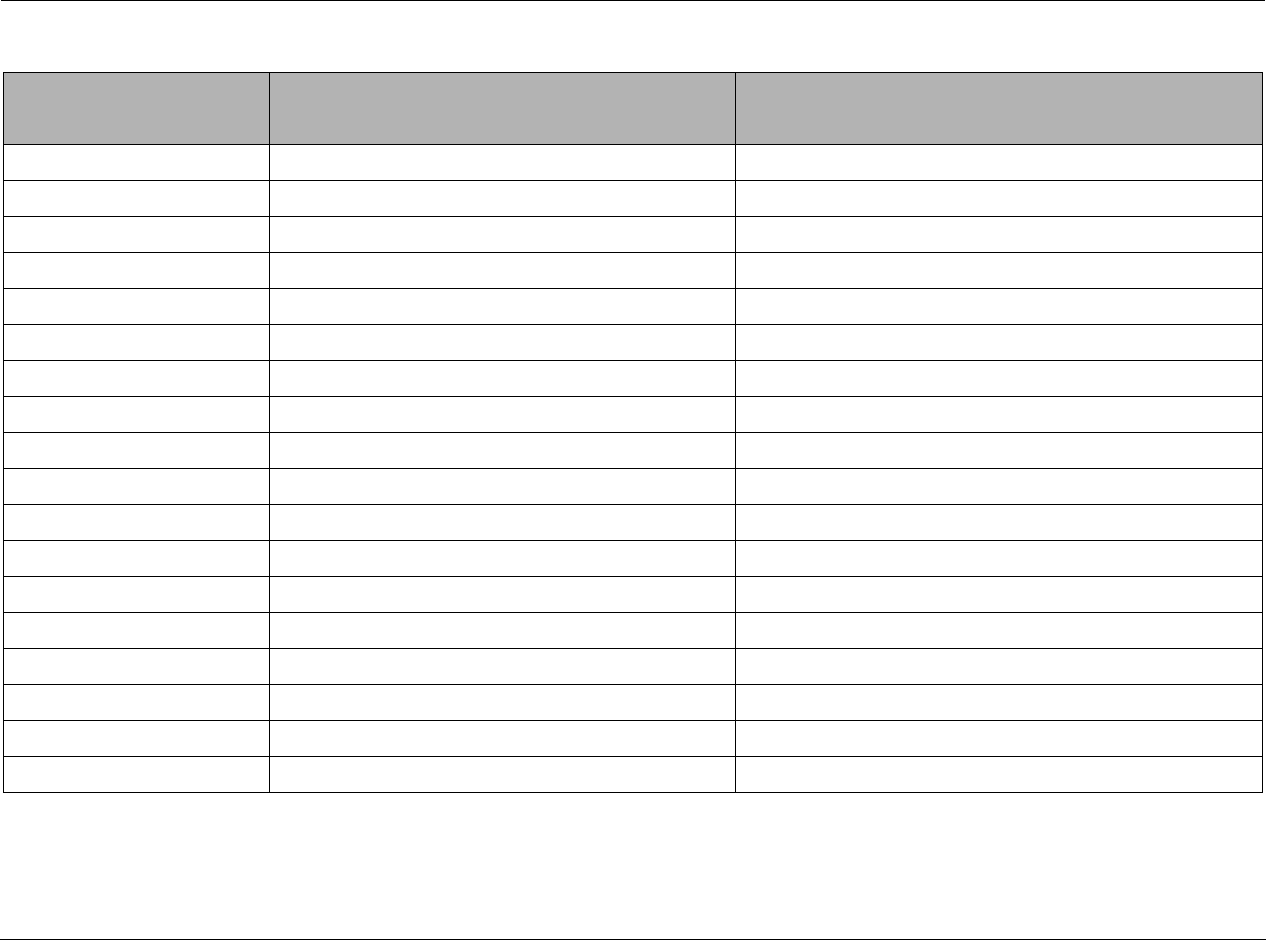
Appendix D Lexicon
D-6
3-DIGIT PRE-PROGRAMMED CODES WORKSHEET
COMPONENT MANUFACTURER CODE(S) USED
AUDIO
DVD
CD
SAT
TV
VCR
CABLE
AUX
LIGHT
TAPE
PHONO
TV2
VCR2
DVR
LDP
XM RADIO
IPOD
X-BOX

Numerics
2-channel listening modes, 3-25
2-LINE OSD parameter, 3-4
5.1-channel direct inputs, 3-28
5-channel listening modes, 3-25
7.1-channel direct inputs, 3-28
7-channel listening modes, 3-25
A
A/D SAMPLE RATE parameter, 3-18
A/V SYNC DELAY parameter, 3-18
advanced video
BRIGHTNESS parameter, 3-22
COLOR parameter, 3-22
COMPONENT ENHANCE parameter, 3-22
CONTRAST parameter, 3-22
DCDi INTERPOL parameter, 3-21
FILM DETECTION parameter, 3-21
FILM EDIT DETECT parameter, 3-21
FLESHTONE NR parameter, 3-22
INPUT TYPE parameter, 3-20
NOISE REDUCTION parameter, 3-21
SHARPNESS parameter, 3-20
TEST PATTERNS parameter, 3-22
X-COLOR SUPPRESS parameter, 3-21
ADVANCED VIDEO menu, 3-18, 3-20
ALL input parameter selection, 3-12
ANLG AUDIO parameter, 3-17
arrow buttons, 2-11
ASPECT RATIO parameter, 3-4
audio
analog audio input setup, 3-17
AUDIO CONTROLS menu, 4-2
AUDIO STATUS menu, 4-3
digital audio input setup, 3-16
HDMI AUDIO OUT parameter, 3-4
rear panel connectors, 2-6
TONE CONTROLS parameter, 4-3
AUTO EQ parameter, 4-2
AUTO SETTINGS parameter, 3-9
autocalibration
AUTO EQ parameter, 4-2
AUTO SETTINGS parameter, 3-9
EQ PRESET parameter, 4-2
FULL AUTOCAL menu, 3-7
MANUAL setup menu, 3-7, 3-9
microphone input connector, 2-6
SEMI AUTOCAL menu, 3-7
SPEAKER/EQ SETUP menu, 3-6
B
BASS parameter, 4-3
battery installation, 1-4
BRIGHTNESS parameter, 3-5, 3-22
C
CAL NOISE parameter, D-2–D-3
CENTER WIDTH parameter, 3-32
COLOR parameter, 3-22
command matrix, 2-11
COMPONENT ENHANCE parameter, 3-22
component rear panel connectors, 2-7
CONNECTION parameter, 3-4
CONTRAST parameter, 3-22
cross-color interference, 3-21
Customizing input names, 3-15
D
DCDi INTERPOL parameter, 3-21
Declaration of Conformity, A-4
default video source settings, 3-21
DIG AUDIO parameter, 3-16
DIG/ANLG AUTO parameter, 3-17
DIMENSION parameter, 3-32
DISPLAY SETUP menu, 3-2–3-3, 3-30, 3-32–3-33
DISPLAY TYPE parameter, 3-3
dock input
2-line display characteristics, 5-5
charging the iPod, 5-7
connecting to the RV-5, 5-4
controlling the iPod, 5-6
DOCK AUTO POWER parameter, 3-33
Dock Functionality, 5-4
docking the iPod, 5-5
front panel controls, 5-6
optional accessory, 1-3
overview, 2-8
rear panel connector, 2-7
remote control, 5-6
removing the iPod, 5-7
selecting the insert, 5-4
ZONE 2 OUT parameter, 3-19
documentation conventions, 1-ii
DOLBY
configuration menu, 3-2
Dolby
Dolby Digital modes, 3-24
DTS + DOLBY modes, 3-23
listening modes descriptions, 3-27
surround configuration menu, 3-30
DOWNMIX parameter selection, 3-18
DSP listening modes descriptions, 3-28
DTS
DTS + DOLBY modes, 3-23
Index

Index Lexicon
I-2
DTS modes, 3-25
listening modes descriptions, 3-27
surround configuration menu, 3-30
E
EQ ADJUST parameter, 4-3
EQ PRESET parameter, 4-2
F
favorite channel
access, C-9
setup, C-9
FILM DETECTION parameter, 3-21
FILM EDIT DETECT parameter, 3-21
FLESHTONE NR parameter, 3-22
front panel
display, 2-3
overview, 2-2
front panel display
BRIGHTNESS parameter, 3-5
TIME OUT parameter, 3-5
FULL AUTOCAL menu, 3-7
H
HDMI AUDIO OUT parameter, 3-4
HDMI connectors, 2-7
HF SHELF parameter, 4-3
horizontal bar graphs, 2-13–2-14
I
INPUT parameter, 3-12
input selection buttons, 2-3
INPUT SETUP menu, 3-2, 3-14, B-6, D-2–D-3
INPUT setup parameter, 3-14
INPUT TYPE parameter, 3-20
installation considerations, 1-4
iPod
iPod functionality, 5-4
Zone 2 iPod, 5-7
IR (Infra Red)
front panel receiver, 2-3
rear panel connector, 2-7
L
listening modes, 3-23
5.1-channel direct inputs, 3-28
7.1-channel direct inputs, 3-28
analog modes, 3-25
available listening modes, 3-24
descriptions, 3-27
DOLBY CONFIG menu, 3-2
Dolby Digital modes, 3-24
DSP listening modes, 3-28
DTS + DOLBY modes, 3-23
DTS modes, 3-25
LOGIC 7 DEFAULT parameter, 3-31
MODE FAMILY parameter, 3-17
MODE parameter, 3-17
PCM modes, 3-26
selecting, 3-23
SURROUND CONFIG menu, 3-2
surround configuration menu, 3-30
Logic 7
DEFAULT parameter, 3-31
listening modes descriptions, 3-27
surround configuration menu, 3-30
M
Main Zone
input selection buttons, 2-3
INPUT SETUP menu, 3-2
mute levels paramater, 3-33
OFF button, 2-4
maintenance, 6-11
MANUAL setup menu, 3-7, 3-9
menu
AUDIO CONTROLS menu, 4-2, B-2
DISPLAY SETUP menu, 3-2–3-3, B-4
DOLBY CONFIG menu, 3-2
INPUT SETUP menu, 3-2, B-6
menu arrows, 2-9, 2-11
menu item selection, 2-9, 2-11
menu options, 2-11
MUTE LEVELS menu, 3-2
navigation, 2-9
overview, 2-9
POWER ON SETTINGS menu, 3-2
SELECT button, 2-9
SETUP menu, 3-2, B-3
SPEAKER/EQ SETUP menu, 3-2, B-5
SURROUND CONFIG menu, 3-2, B-4
VIDEO CONTROLS menu, 4-4, B-2
MENU TIME OUT parameter, 3-4
microphone, 3-7
MODE buttons, 2-4
MODE FAMILY parameter, 3-17
MODE parameter, 3-17, 3-32
MUTE button, 2-4
MUTE LEVELS menu, 3-2, 3-33
N
NAME parameter, 3-14
NIGHT parameter, 3-32
NOISE REDUCTION parameter, 3-21
O
OSD (On-Screen Display)
2-LINE OSD parameter, 3-4
MENU TIME OUT parameter, 3-4
output aspect ratio, 4-4
OUTPUT LEVELS menu, 3-12

MV-5 Index
I-3
P
PANORAMA parameter, 3-32
PC input
controls, 5-2
overview, 2-8
playing PC media, 5-3
setting up to play, 5-2
USB connector, 2-6
ZONE 2 OUT parameter, 3-19
power
AC input connector, 2-7
POWER ON SETTINGS menu, 3-2, 3-33
rear panel switch, 2-7
standby button, 2-4
preamplifier rear panel connectors, 2-6– 2-7
R
rear panel
connectors, 2-6–2-7
overview, 2-5
remote control
adjusting the touch screen contrast, C-7
advanced customizing tools, C-6
backlight time out, C-7
battery installation, 1-4
button learning, C-4
buttons overview, 2-10
cloning, C-11
command matrix, 2-11–2-15
customizing the touch screen, C-7
erasing commands, C-13
favorite channel access, C-9
favorite channel setup, C-9
hiding and adding pages, C-12
LCD display overview, 2-10
light button, 2-11, C-2
lock feature, C-6
macro setup, C-10
operation considerations, 2-8
optional RF-1 receiver, 1-3, C-14
overview, 2-8
pre-programmed codes, C-3, C-15
pre-programmed codes worksheet, D-6
programming, C-2
punch through commands, C-11
recall pre-programming, C-4
restoring factory default settings, C-14
setup, C-3
system volume setup, C-11
transmitting icon, C-2
using the code library, C-15
restoring the factory defaults, 6-11
routine maintenance, 6-11
RS-232 connector, 2-6
RV-5
About, 1-2
Available Options, 1-3
Declaration of Conformity, A-4
installation considerations, 1-4
Product Registration, 1-2
routine maintenance, 6-11
specifications, A-2
What’s in the Box, 1-3
RV-5 error messages, 6-6
autocal errors, 6-7
video errors, 6-6
S
safety instructions, 1-ii
SELECT button, 2-9
SEMI AUTOCAL menu, 3-7
SETUP menu, 3-2
SHARPNESS parameter, 3-20
SPEAKER/EQ SETUP menu, 3-6
speakers
crossover setup, 3-10
FULL AUTOCAL menu, 3-7
MANUAL setup menu, 3-7, 3-9
manual TEST TONE, 3-12
output levels INPUT parameter, 3-12
OUTPUT LEVELS menu, 3-12
SEMI AUTOCAL menu, 3-7
SPEAKER DISTANCES menu, 3-11
SPEAKER/EQ SETUP menu, 3-2, 3-6
SPEAKERS manual setup menu, 3-10
SUB HPF parameter, 3-11
SUB MODE parameter, 3-11
SUB/LFE LPF parameter, 3-11
SUBWOOFERS parameter, 3-11
UNITS parameter, 3-12
specifications, A-2
Standby button, 2-4
SUB HPF parameter, 3-11
SUB MODE parameter, 3-11
SUB/LFE LPF parameter, 3-11
SUBWOOFERS parameter, 3-11
SURROUND CONFIG menu, 3-2, 3-30
T
TEST PATTERNS parameter, 3-22
TEST TONE parameter, 3-12
TIME OUT parameter, 3-5
tone controls, 4-3
BASS parameter, 4-3
TREBLE parameter, 4-3
TREBLE parameter, 4-3
trigger
output connectors, 2-6
TRIGGER 2 parameter, 3-18
troubleshooting, 6-2
U
UNITS parameter, 3-12
V
video
ADVANCED VIDEO menu, 3-18, 3-20
ASPECT RATIO parameter, 3-4
CONNECTION parameter, 3-4

Index Lexicon
I-4
default video source settings, 3-21
output aspect ratio, 4-4
rear panel connectors, 2-7
VIDEO CONTROLS menu, 4-4
VIDEO IN setup parameter, 3-15
VIDEO OUT parameter, 3-16
video resolutions table, 6-9
VIDEO STATUS menu, 4-5
V-PROCESS parameter, 3-15
volume
adjust Main Zone level, 2-3
adjust Zone 2 level, 2-3
knob, 2-3
MUTE LEVELS menu, 3-33
V-PROCESS parameter, 3-15
X
X-COLOR SUPPRESS parameter, 3-21
Z
Zone 2
input selection buttons, 2-3
INPUT SETUP menu, 3-2
iPod, 5-7
mute levels paramater, 3-33
OFF button, 2-4
rear panel connectors, 2-6
ZONE-2 OUT parameter, 3-18

Harman Specialty Group offers the following warranty
on this product:
What is the Duration of this Warranty?
This warranty will remain in effect for three (3) years
from the original date of purchase.
Who is Covered?
This warranty may be enforced by the original pur-
chaser and subsequent owners during the warranty
period, provided the original dated sales receipt or
other proof of warranty coverage is presented at time
of service.
What is Covered?
This warranty covers all defects in material and
workmanship on this product, except as specified
below. The following are not covered:
1. Damage resulting from:
A. Accident, misuse, abuse, or neglect.
B. Failure to follow instructions contained in the
user guide.
C. Repair or attempted repair unauthorized by
Harman Specialty Group.
D. Failure to perform recommended periodic
maintenance.
2. Causes other than product defects, including lack
of skill, competence, or experience on the part of
the owner.
3. Damage occurring during any shipment of this
product. Claims for shipping damages must be
made with the carrier.
4. Damage to a unit that has been altered, or on
which the serial number has been defaced, modi-
fied, or removed.
What Expenses will Harman Specialty Group
Assume?
Harman Specialty Group will pay all labor and material
expenses for covered items. Payment of shipping
charges is discussed in the next section of the warranty.
How is Service Obtained?
When this product needs service, write, telephone, or
fax Harman Specialty Group to request information
about where the unit should be taken or sent. When
making a written request, please include your name,
complete address, and daytime telephone number;
the product model and serial numbers; and a descrip-
tion of the problem. Do not return the unit to Harman
Specialty Group without prior authorization.
When Shipping a Product for Service . . .
1. Pay any initial shipping charges, which are the
responsibility of the owner. If necessary repairs are
covered by this warranty, Harman Specialty
Group will pay return shipping charges to any
destination in the United States using the carrier
of our choice.
2. Pack the unit securely. Package insurance is
strongly recommended.
3. Include a copy of the original dated sales receipt.
(A copy of the original dated sales receipt must be
presented whenever warranty service is required.)
4. Do not include accessories such as power cords or
user guides unless instructed to do so.
What are the Limitations of Implied
Warranties?
Any implied warranties, including warranties of mer-
chantability and fitness for a particular purpose, are
limited in duration to the length of this warranty.
What Certain Damages are Excluded?
Harman Specialty Group’s liability for a defective
product is limited to repair or replacement of that
product, at our option. Harman Specialty Group shall
not be liable for damages based on inconvenience;
loss of use of the product; loss of time; interrupted
operation; commercial loss; or any other damages,
whether incidental, consequential, or otherwise.
How do State Laws Relate to this Warranty?
Some states do not allow limitations on the duration of
implied warranties and/or the exclusion or limitation
of incidental or consequential damages. As such, the
above limitations may not apply.
This warranty is not enforceable outside of North
America. This warranty provides specific legal rights.
Additional rights may be provided by some states.
LIMITED WARRANTY
Harman Specialty Group
3 Oak Park
Bedford, MA 01730-1413
USA
Customer Service
Tel 781-280-0300
Fax 781-280-0495 (Sales)
Fax 781-280-0499 (Service)
Tel 781-280-0300
Fax 781-280-0490
www.lexicon.com

!ª(ARMANª)NTERNATIONALª#OMPANY
0ART.O\2EV\
0RODUCT3HIPMENTS
-IDDLESEX"LDG
"ILLERICA-!
#USTOMER3ERVICE
4ELEPHONE
3ALES&AX
3ERVICE&AX
/AK0ARK$RIVE
"EDFORD-!
4EL
&AX
WWWLEXICONCOM