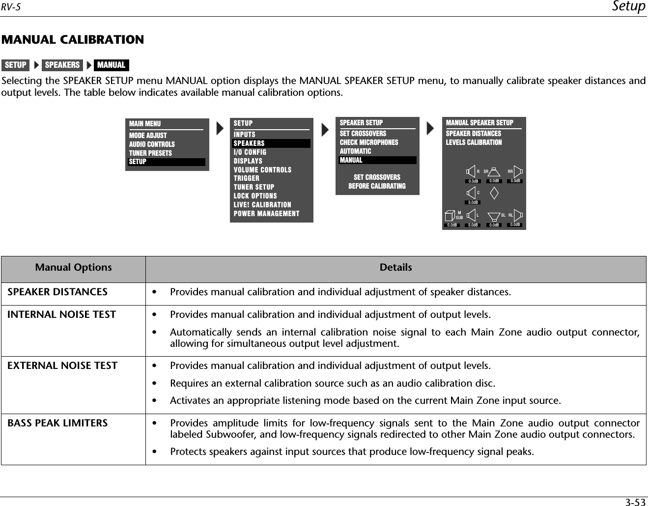
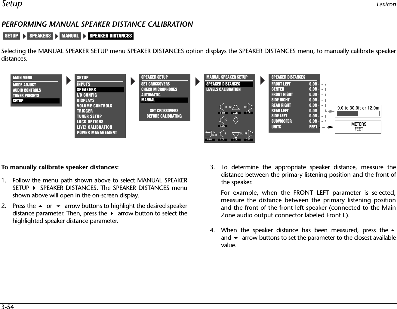
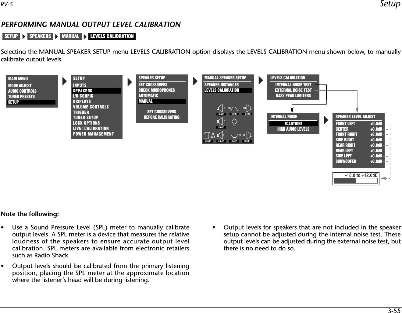
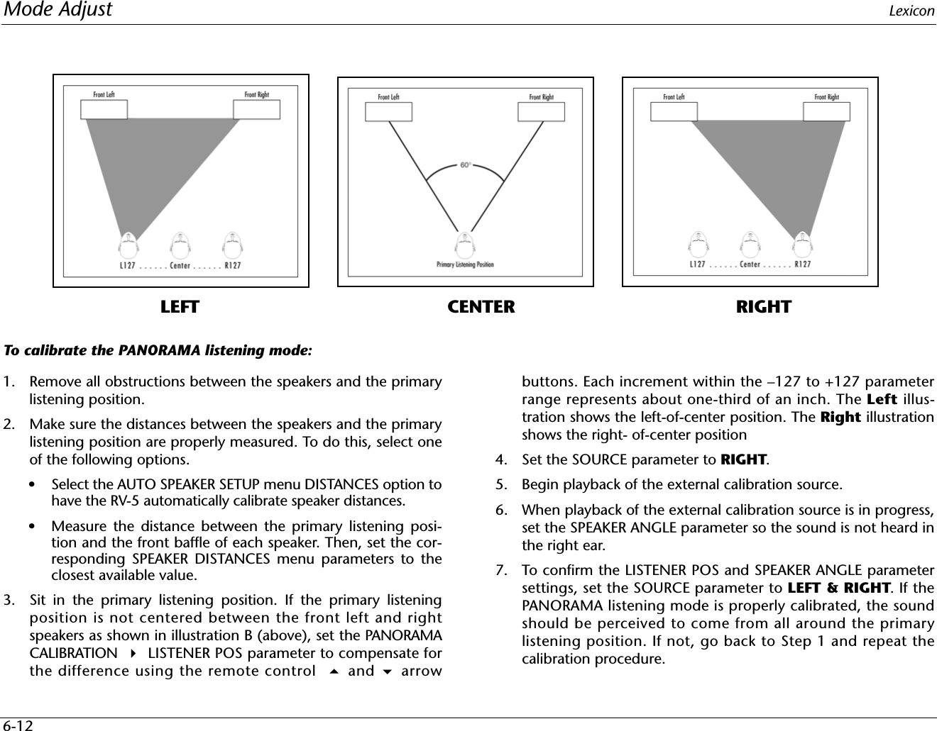
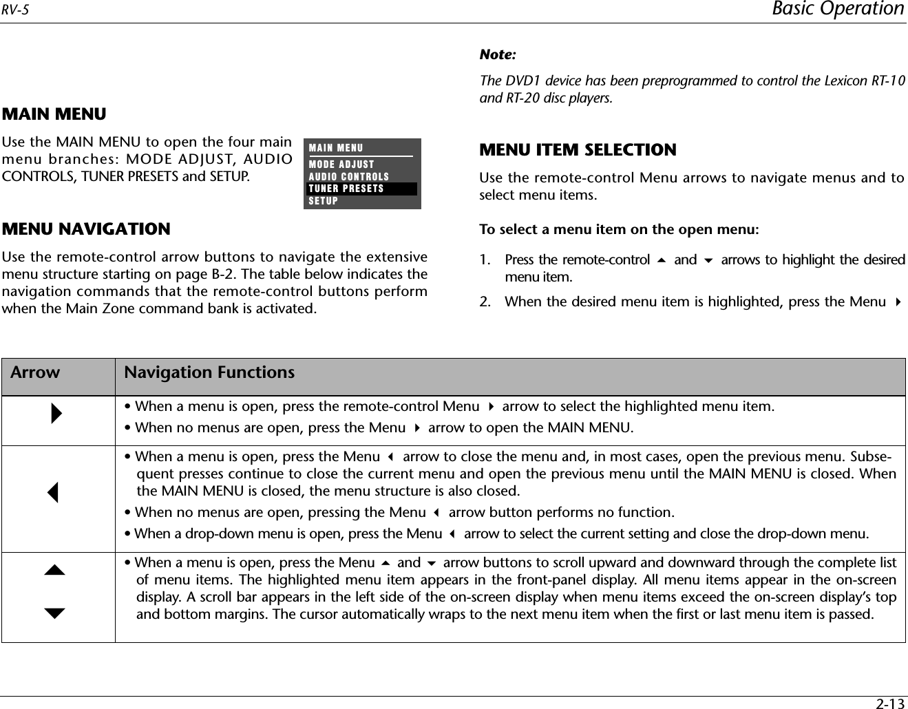
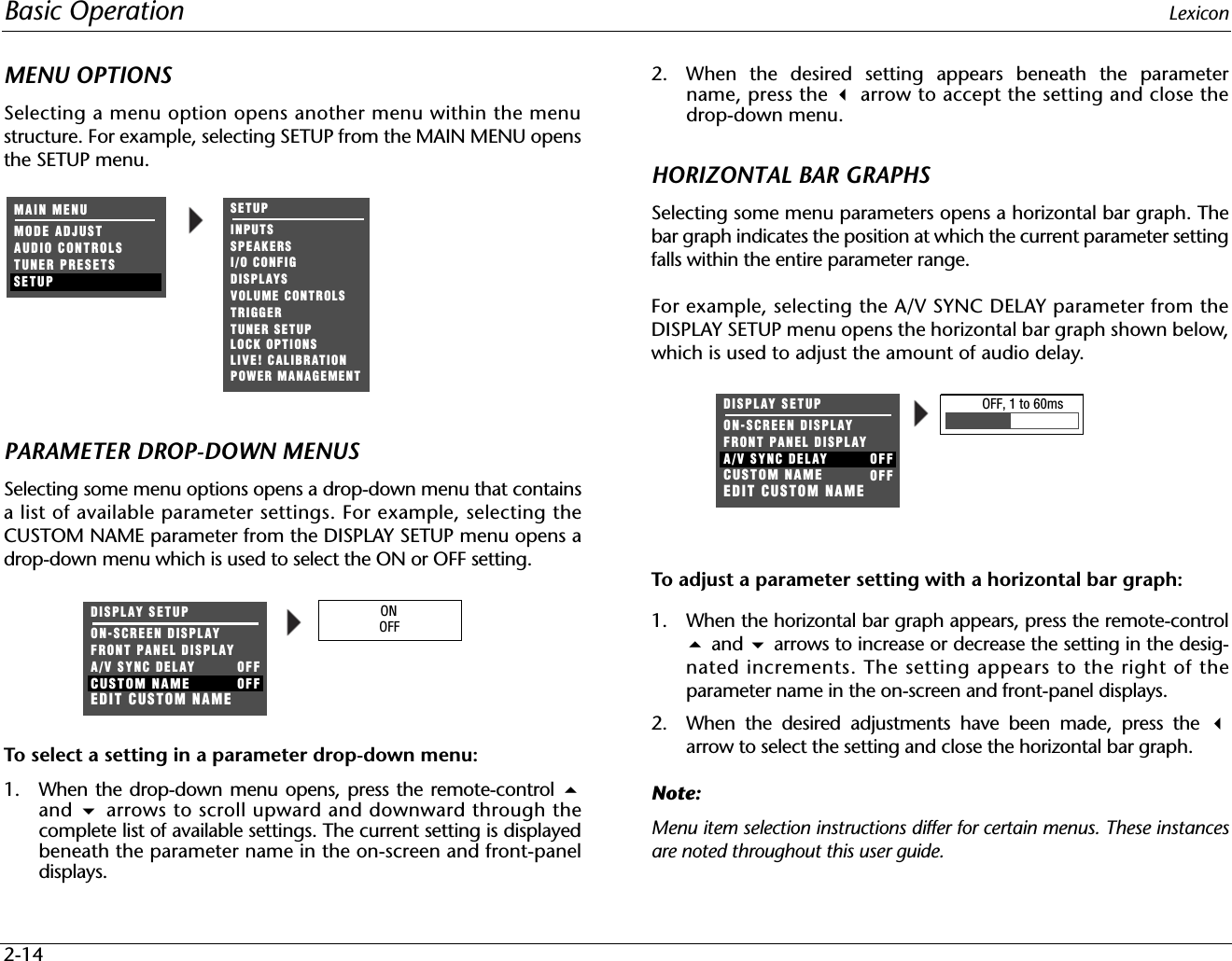
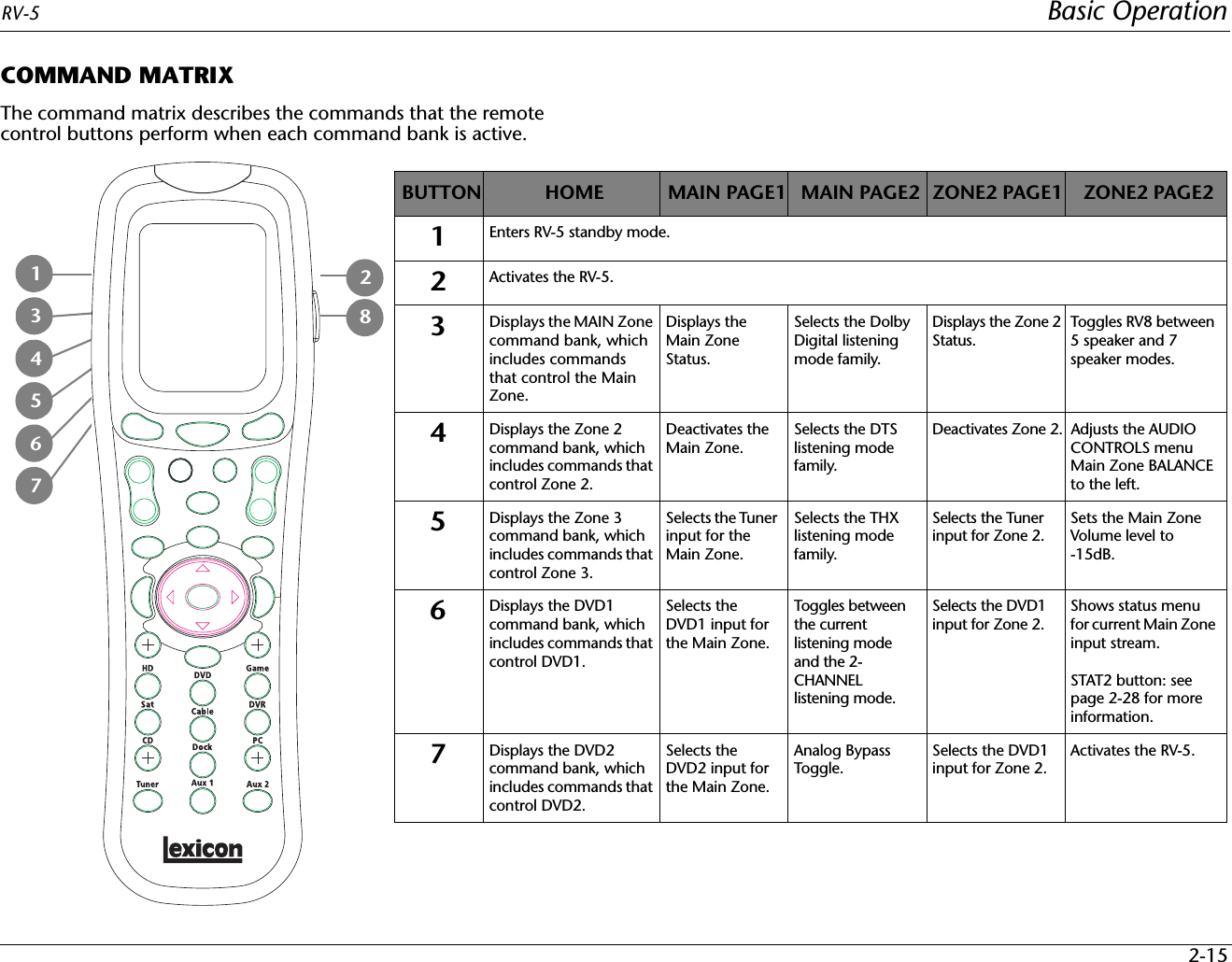
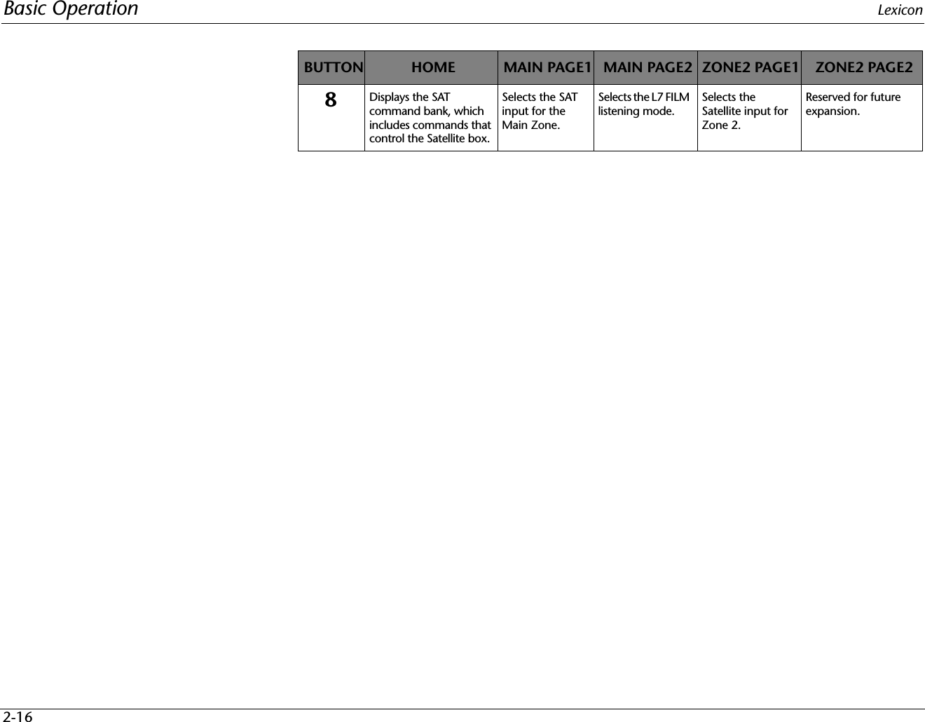
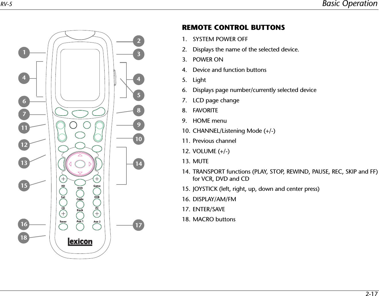
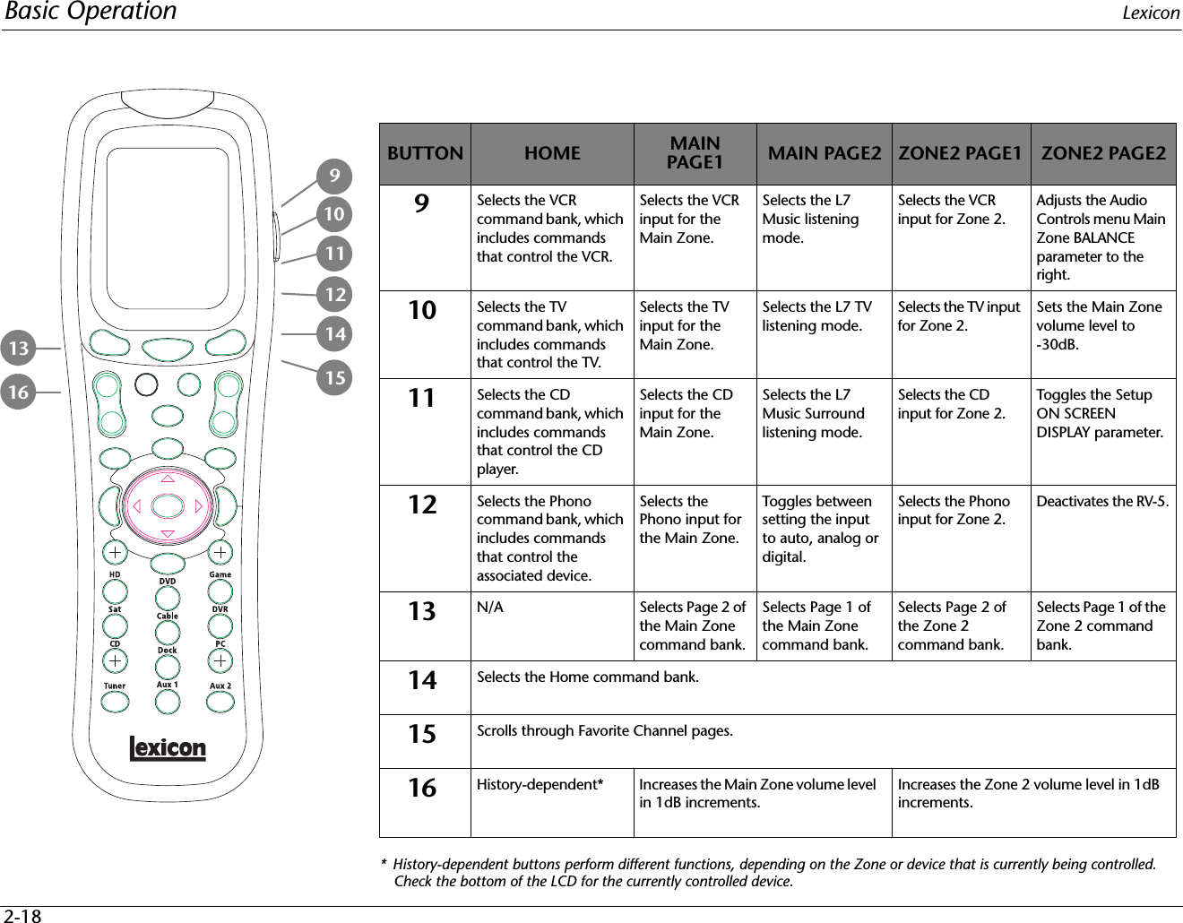
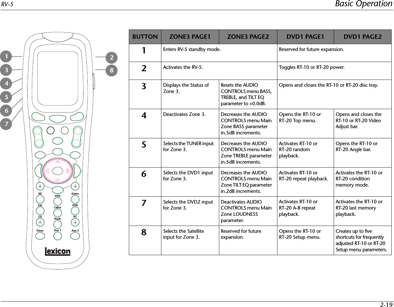
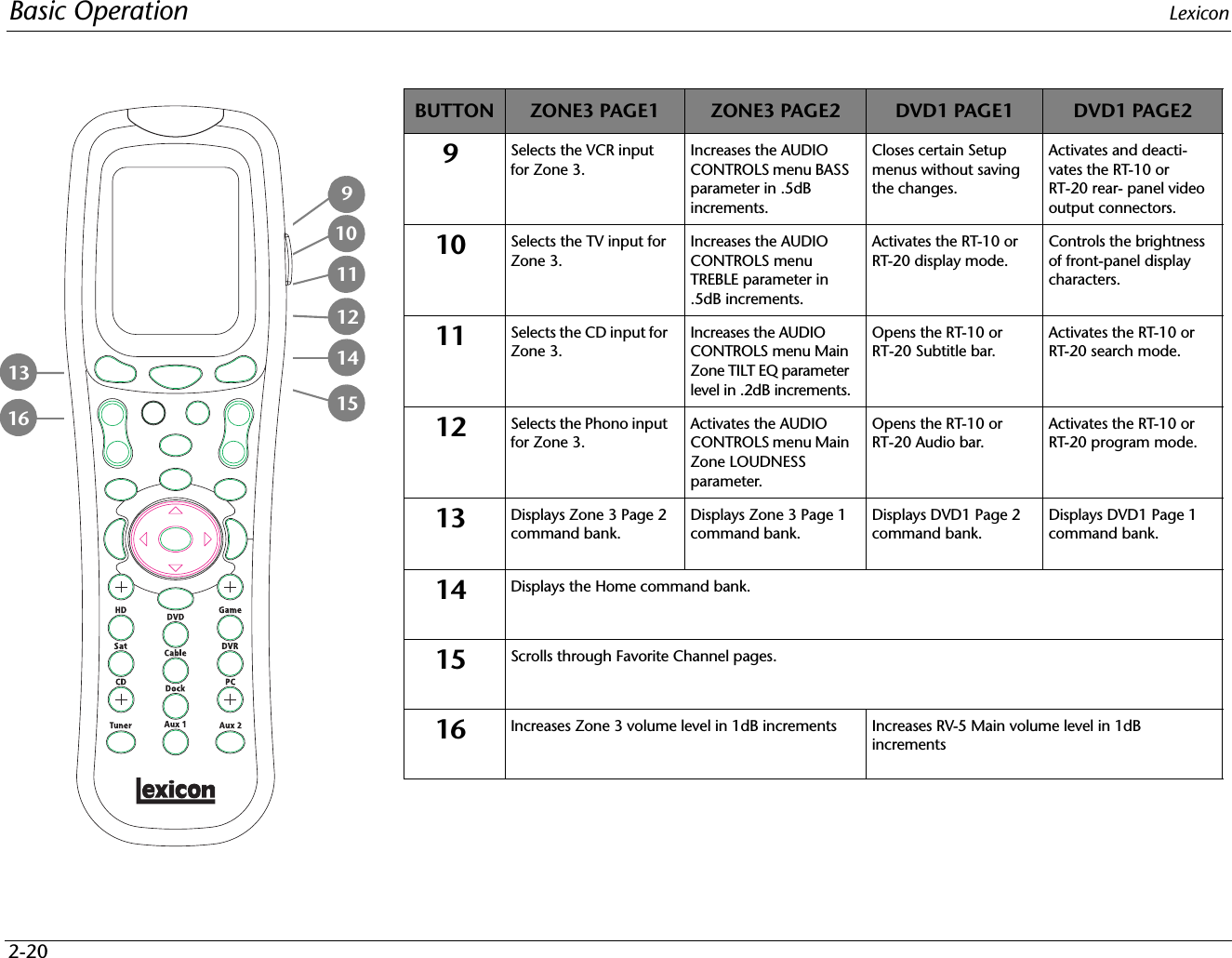
Woori Technology RV-5 AV RECEIVER User Manual RV5 Outside Front Cover
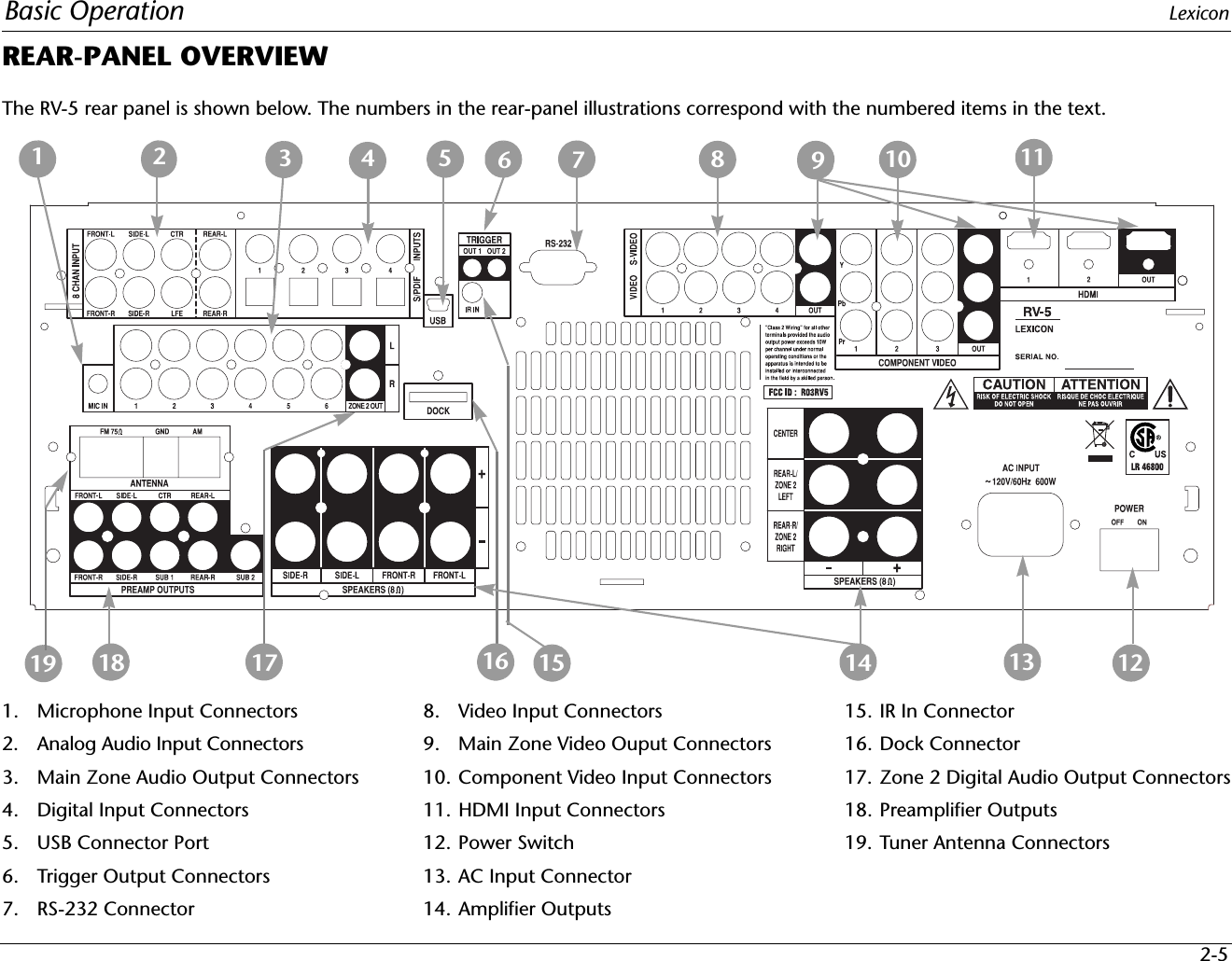
Woori Technology Inc AV RECEIVER RV5 Outside Front Cover
UserManual.wiki
>
Woori Technology
>
RV 5 User Manual
USERS MANUAL
Navigation menu
Upload a User Manual
Namespaces
Wiki Guide
HTML
PDF
Info
Views
User Manual
Discussion / Help
Navigation

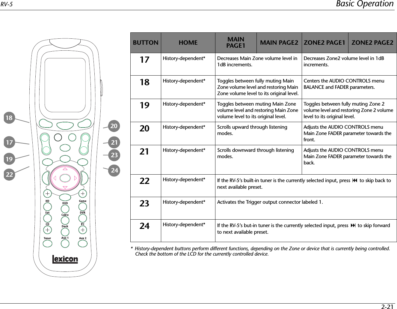
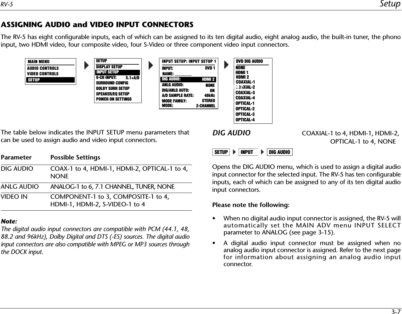
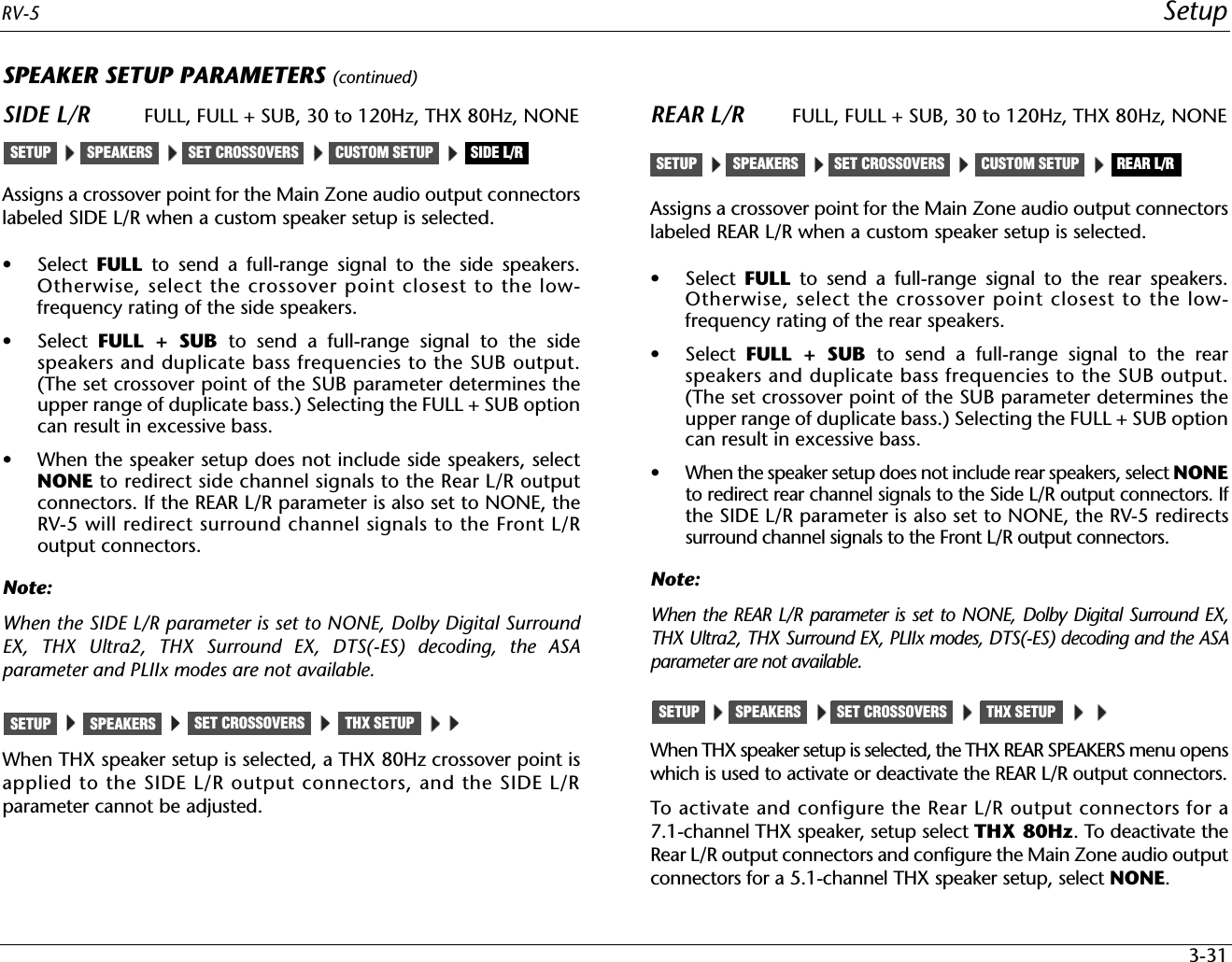
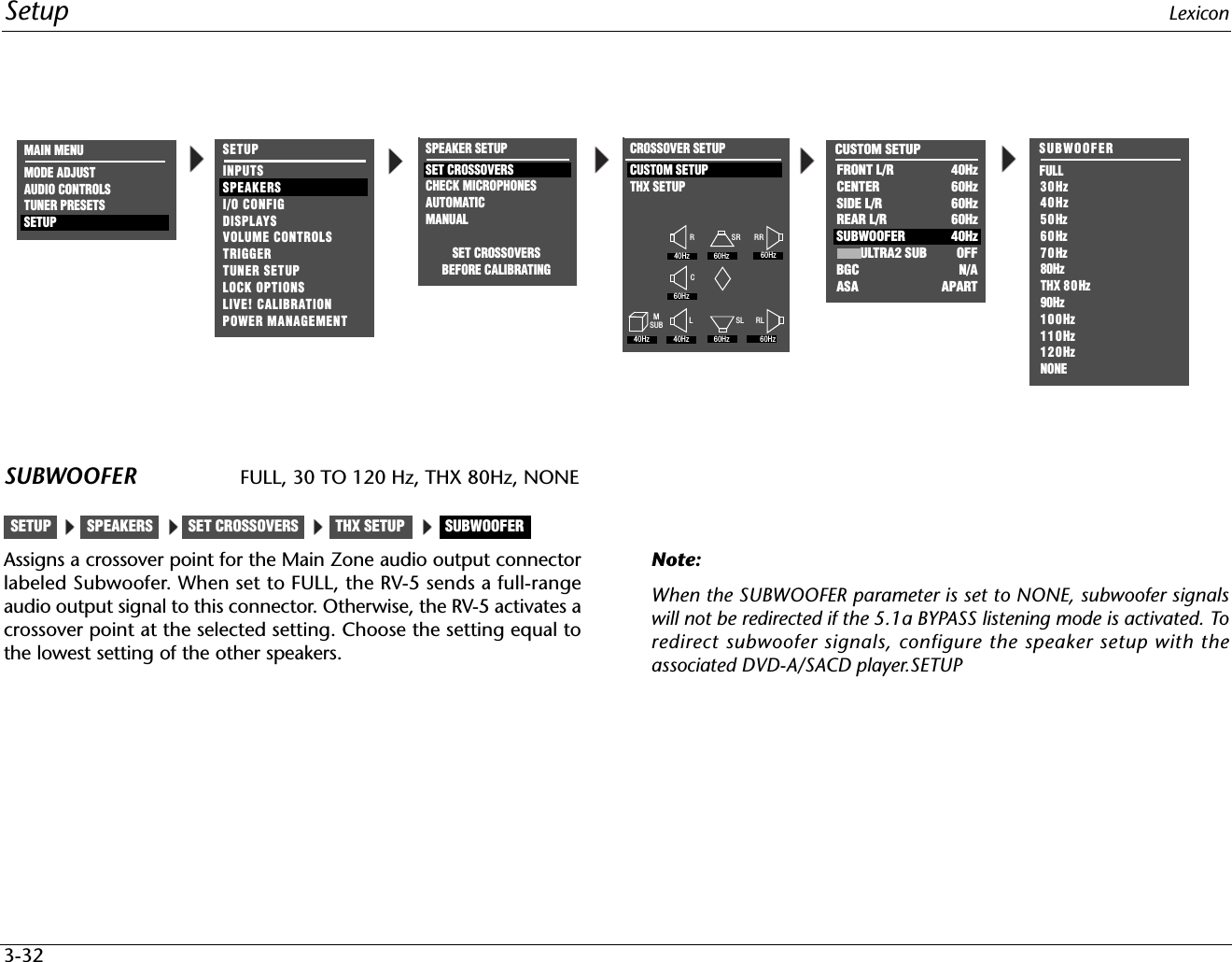
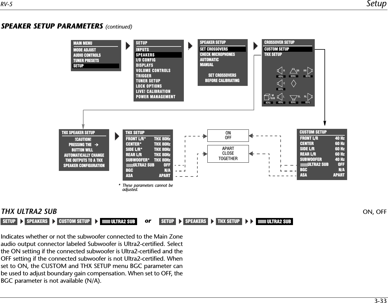
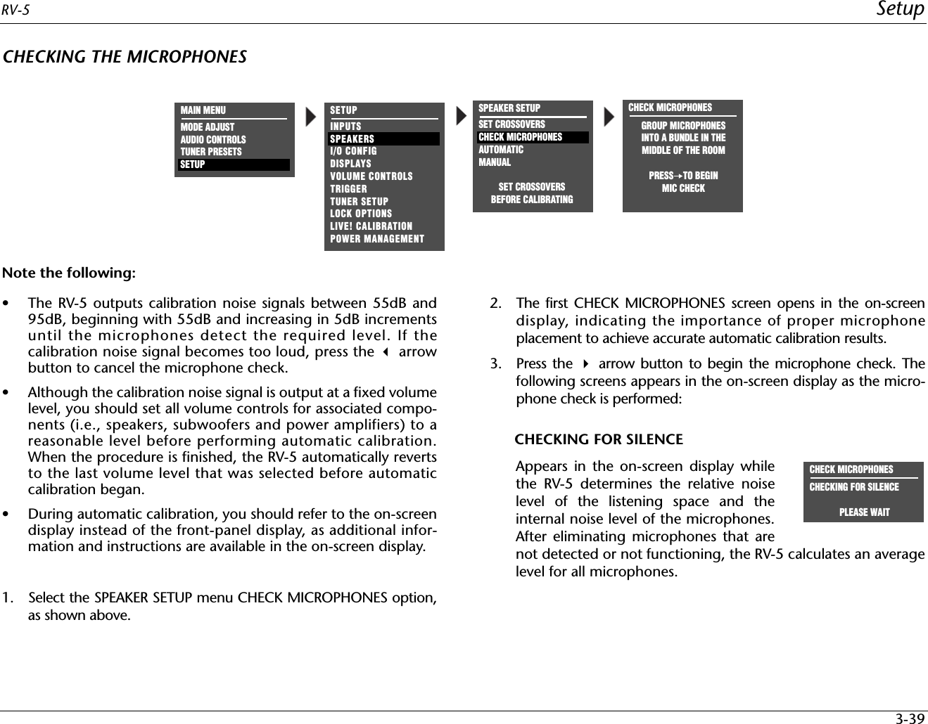
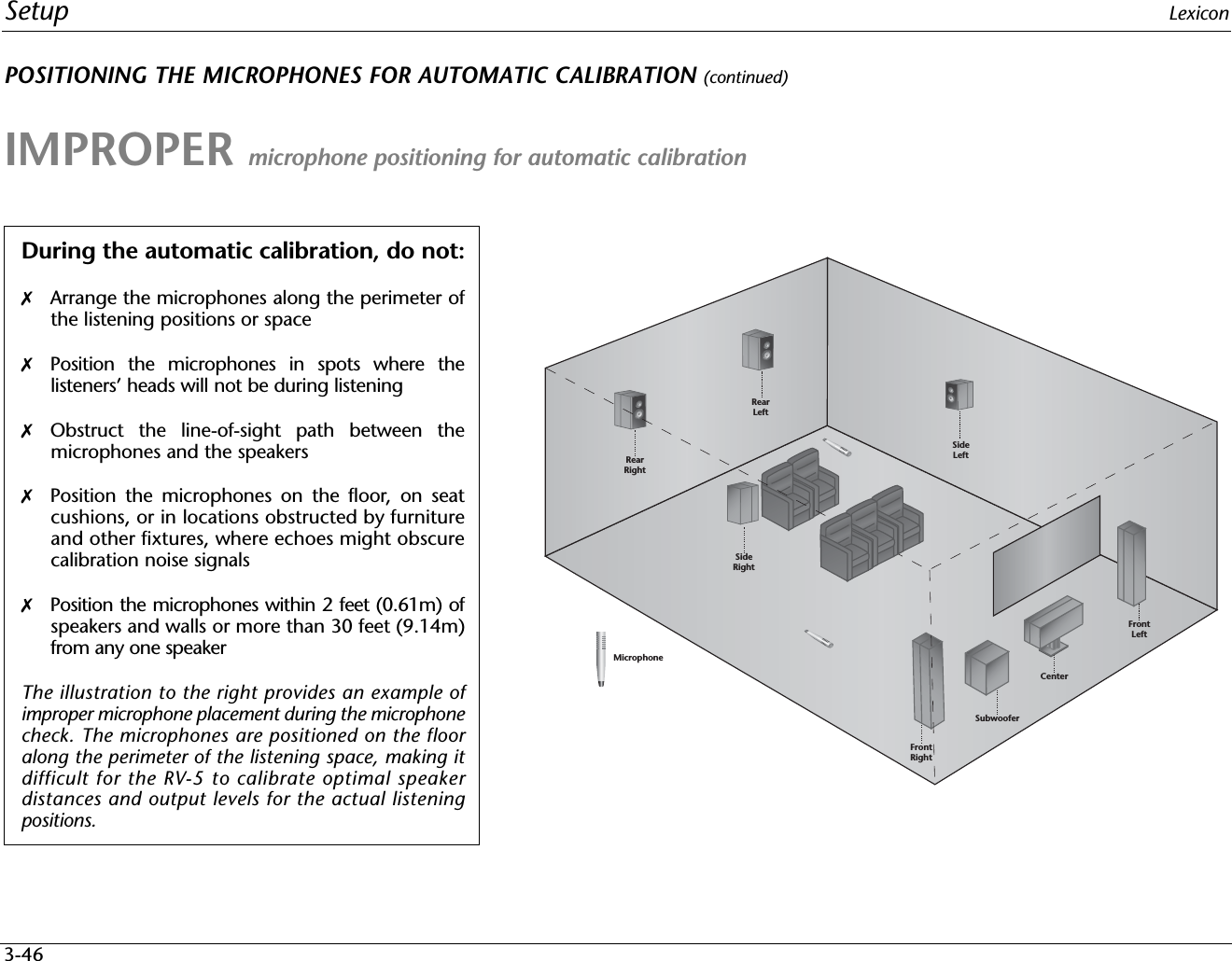
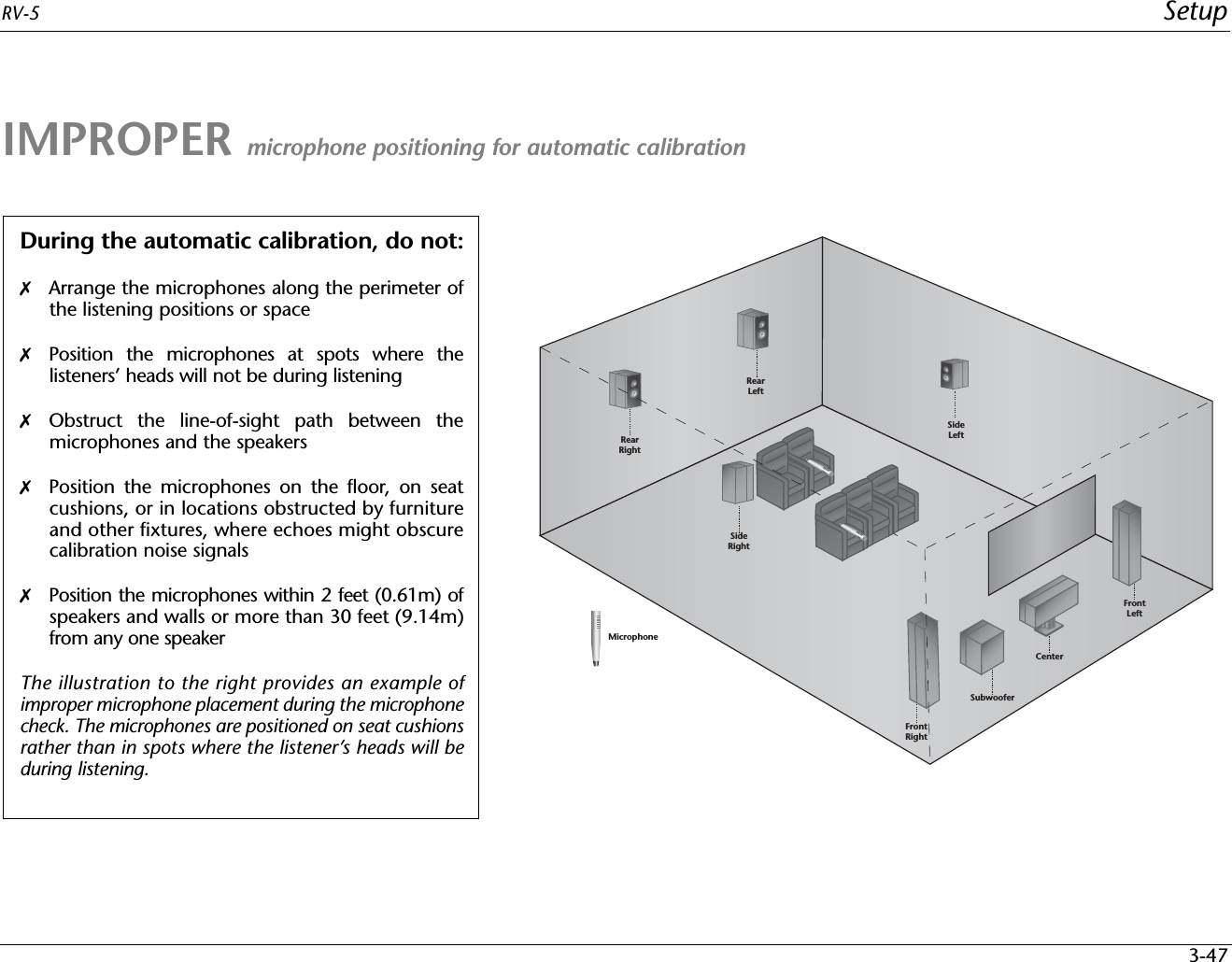
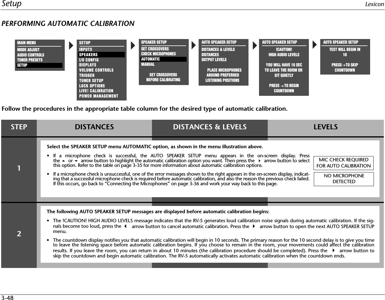
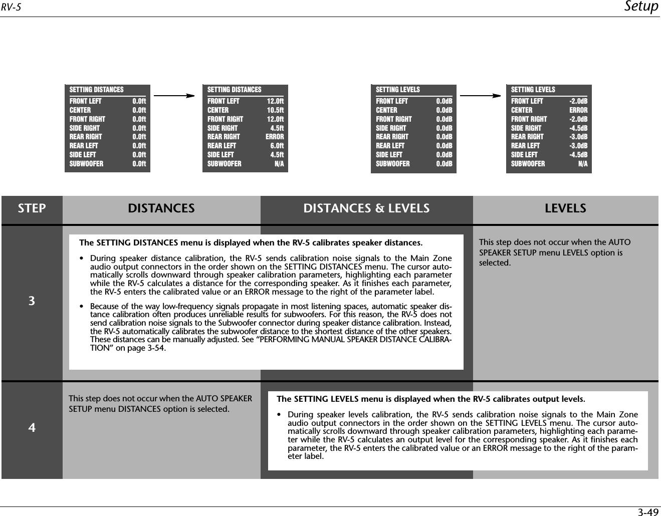
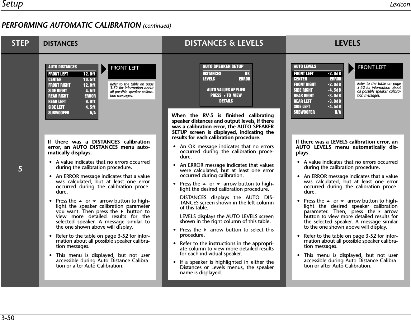
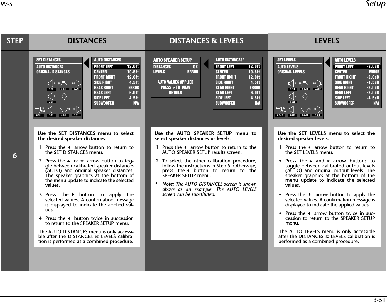
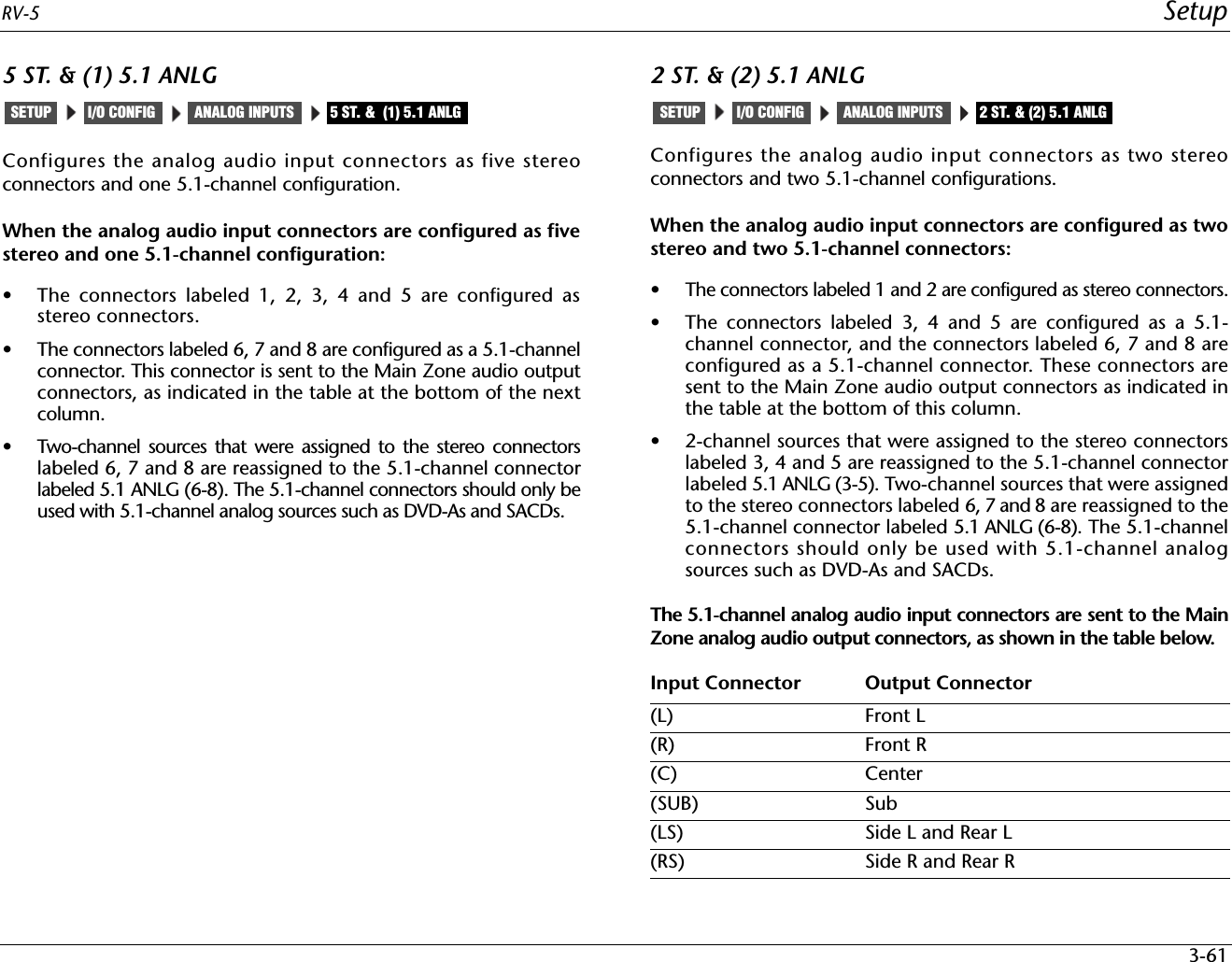
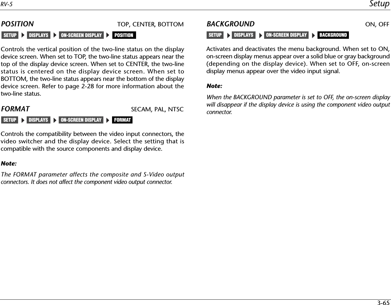
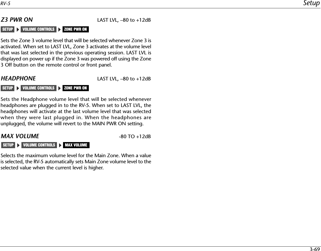
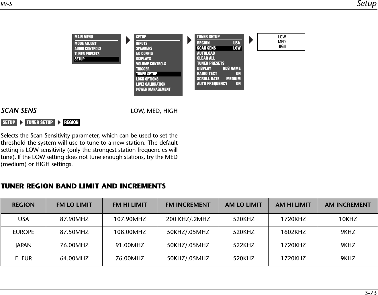
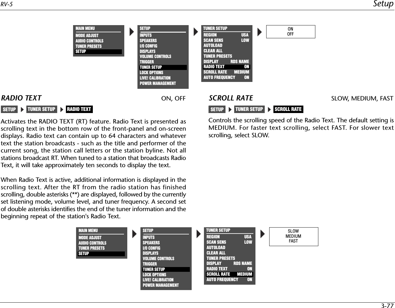
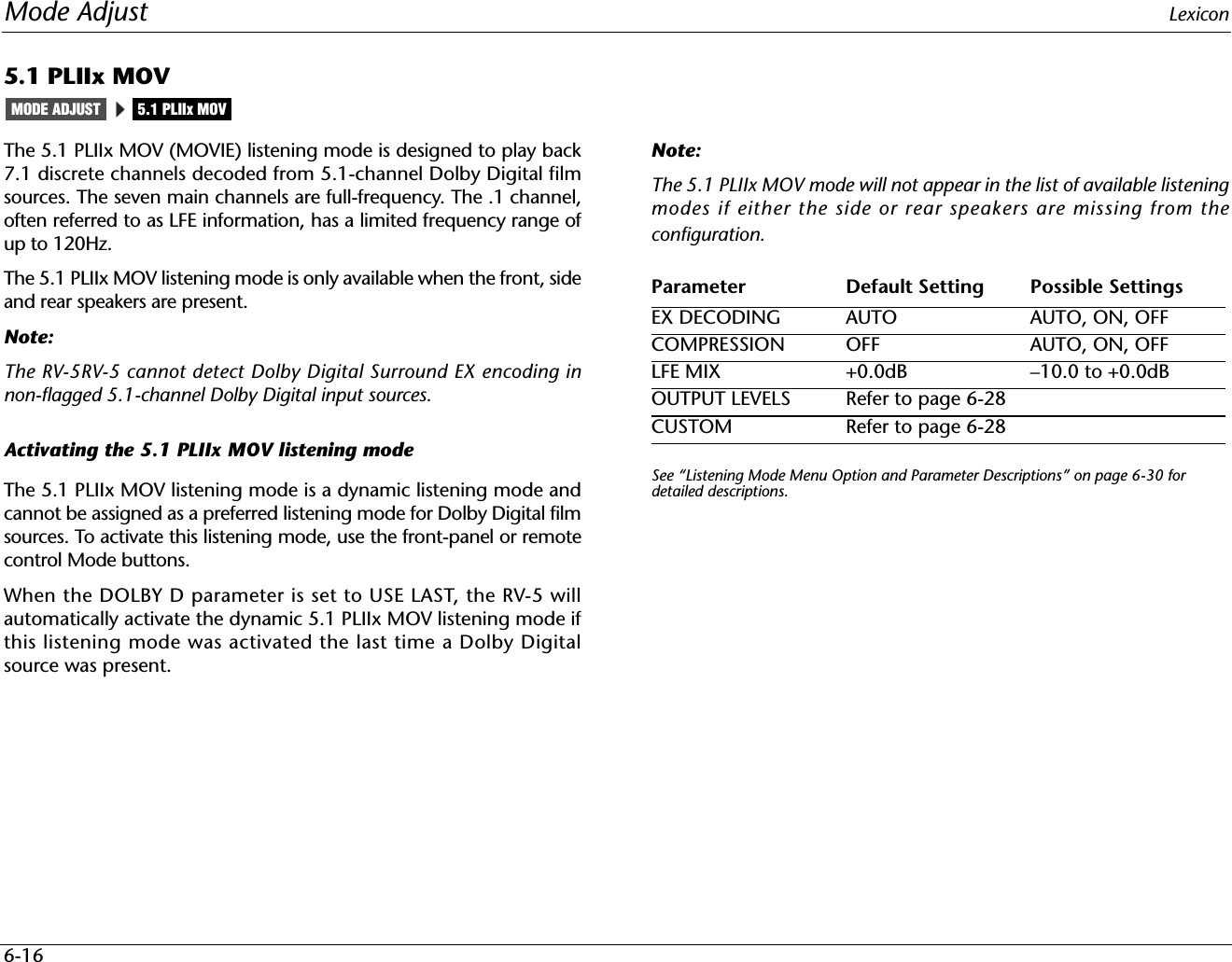
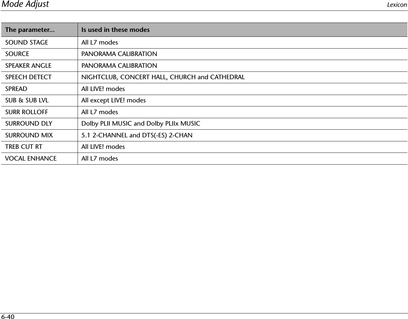
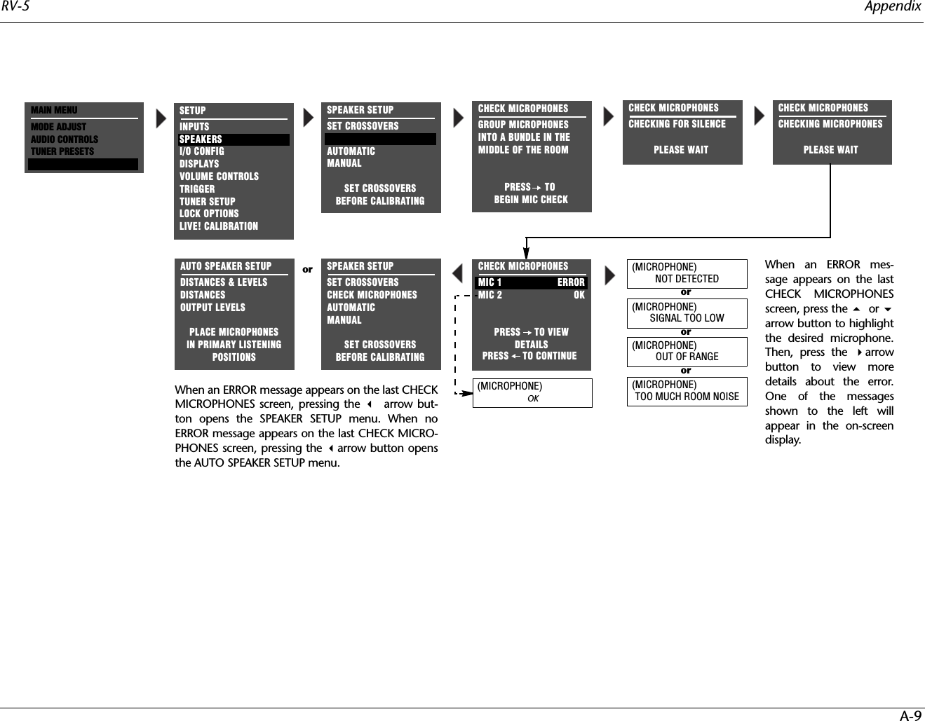
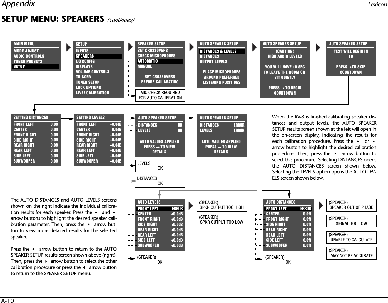
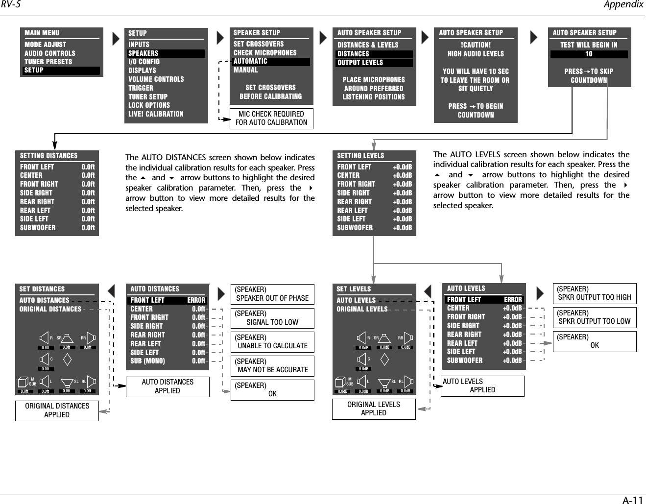
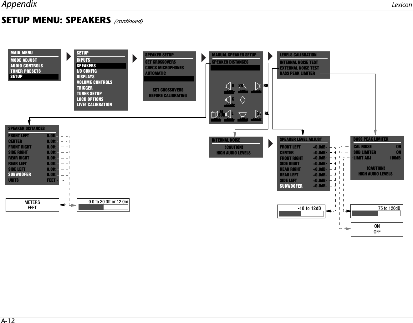
![Setup Lexicon3-52PERFORMING AUTOMATIC CALIBRATION (continued) Message Description TroubleshootingThe RV-5 successfully calibrated the value for the selected speaker without error.•N/AThe selected speaker is not present in the speaker setup.• Set the corresponding CUSTOM or THX SETUP menu parameter to include the selectedspeaker in the speaker setup. (The RV-5 only calibrates values for speakers that are included inthe speaker setup.)The microphones detected out-of-phase calibration noise signals, but the cali-brated value is still accurate.• Examine speaker/associated amplifier connections to ensure that speaker wires are not crossed.• Dipolar speakers could cause this error. However, the RV-5 does not report this error unless atleast half of the microphones detect out-of-phase calibration noise signals.• Reflections from room objects could cause this error.• Drivers intentionally wired out-of-phase could cause this error.The microphones detected calibration noise signals at an unusually low level.• The microphones might be positioned more than 30 feet (9.14m) from the selected speaker or in alocation where echoes obscure calibration noise signals. Refer to the placement examples on pages3-40 to 3-44 to confirm that the microphones are appropriately positioned for automatic calibration.• Examine microphone input connections to ensure that the microphones are properly con-nected to the RV-5 and that microphone cable plugs are fully inserted for a solid connection.The microphones did not detect calibra-tion noise signals or the RV-5 could not calculate a value.• Refer to the microphone placement examples on pages 3-41 to 3-45 to confirm that themicrophones are appropriately positioned for automatic calibration.• Examine microphone input connections to ensure that the microphones are properly con-nected to the RV-5 and that microphone cable plugs are fully inserted for a solid connection.One or more microphones did not detect calibration noise signals at a reasonable level. The calibrated value could be inac-curate.• Refer to the microphone placement examples on pages 3-41 to 3-45 to confirm that themicrophones are appropriately positioned for automatic calibration.The microphones detected calibration noise signals at an unusually high level.• Decrease associated amplifier volume levels – including (if applicable) powered subwoofer amplifiers.• The microphones may be positioned too close (within 2 feet [0.61m]) of the selected speaker.Refer to the microphone placement examples on pages 3-41 to 3-45 to confirm that the micro-phones are appropriately positioned for automatic calibration.The microphones detected calibration noise signals at an unusually low level.• Increase associated amplifier volume levels – including (if applicable) powered subwoofer amplifiers.• The microphones may be positioned too far away (more than 30 feet [9.14m]) from theselected speaker. See the microphone placement examples on pages 3-41 to 3-45 to confirmthat the microphones are appropriately positioned for automatic calibration.(SPEAKER) OK(SPEAKER)SPEAKER IS NOT ENABLED(SPEAKER)SPEAKER OUT OF PHASE(SPEAKER) SIGNAL TOO LOW(SPEAKER)UNABLE TO CALCULATE(SPEAKER)MAY NOT BE ACCURATE(SPEAKER)SPKR OUTPUT TOO HIGH(SPEAKER)SPKR OUTPUT TOO LOW](https://usermanual.wiki/Woori-Technology/RV-5/User-Guide-785230-Page-96.png)