Woori Technology RV-5 AV RECEIVER User Manual RV5 Outside Front Cover
Woori Technology Inc AV RECEIVER RV5 Outside Front Cover
USERS MANUAL

RV-5 Receiver
User Guide
IMPORTANT SAFETY INSTRUCTIONS
1. Read these instructions.
2. Keep these instructions.
3. Heed all warnings.
4. Follow all instructions.
5. Do not use this apparatus near water.
6. Clean only with a dry cloth.
7. Do not block any ventilation openings. Install in
accordance with the manufacturer’s instructions.
8. Do not install near any heat sources such as
radiators, heat registers, stoves, or other
apparatus (including amplifiers) that produce
heat.
9. Do not defeat the safety purpose of the polarized
or grounding-type plug. A polarized plug has two
blades with one wider than the other. A
grounding-type plug has two blades and a third
grounding prong. The wide blade or the third
prong are provided for your safety. If the provided
plug does not fit into your outlet, consult an
electrician for replacement of the obsolete outlet.
10. Protect the power cord from being walked on or
pinched, particularly at plugs, convenience
receptacles, and the point where they exit from
the apparatus.
11. Only use attachments/accessories specified by
the manufacturer.
12. Use only with the cart, stand,
tripod, bracket or table specified
by the manufacturer, or sold with
the apparatus. When a cart is
used, use caution when moving
the cart/apparatus combination to avoid injury
from tip-over.
13. Unplug this apparatus during lightning storms or
when unused for long periods of time.
14. Refer all servicing to qualified service personnel.
Servicing is required when the apparatus has
been damaged in any way, such as when a power
supply cord or plug is damaged, liquid has been
spilled or objects have fallen into the apparatus,
the apparatus has been exposed to rain or
moisture, does not operate normally, or has been
dropped.
15. Do not expose this apparatus to dripping or
splashing and ensure that no objects filled with
liquids, such as vases, are placed on the
apparatus.
16. To completely disconnect this apparatus from the
AC Mains, disconnect the power supply cord
plug from the AC receptacle.
17. The MAINS cord is intended to be the safety
disconnect device for this apparatus and shall
remain readily operable at all times.
18. Do not expose batteries to excessive heat, such
as sunshine, fire, or the like.
19. This product shall be connected to a MAINS
socket outlet with a protective earthing
connection.
This equipment has been tested and found to
comply with the limits for a Class B digital device,
pursuant to Part 15 of FCC Rules. These limits are
designed to provide reasonable protection against
harmful interference in a residential installation.
This equipment generates, uses, and radiates radio
frequency energy and, if not installed and used in
accordance with the instructions, may cause
harmful interference to radio or television
reception, which can be determined by turning the
equipment off and on. The user is encouraged to try
to correct the interference by one or more of the
following measures:
• Re-orient or relocate the receiving antenna.
• Increase the separation between the equipment and
the receiver.
• Connect the equipment into an outlet on a circuit
different from that to which the receiver is
connected.
• Consult the dealer or an experienced radio/
television technician for help.
Caution
Changes or modifications not expressly approved
by the party responsible for compliance could void
the user's authority to operate the equipment.
Canada
This Class B digital apparatus complies with
Canadian ICES-003.
Cet appareil numérique de la classe B est conforme
à la norme NMB-003 du Canada.
To reduce the risk of fire or electric shock,
do not expose this apparatus to rain or
moisture.
WARNING The lightning flash with arrowhead symbol, The exclamation point within an equilateral
triangle is intended to alert the user to the
presence of important operating and
maintenance (servicing) instructions in the
literature accompanying the product.
within an equilateral triangle, is intended to
alert the user to the presence of uninsulated
“dangerous voltage” within the product’s
enclosure that may be of sufficient magnitude
to constitute a risk of electric shock to persons.

Lexicon Inc.
3 Oak Park
Bedford, MA 01730-1413 USA
Tel 781-280-0300
Fax 781-280-0490
www.harmanspecialtygroup.com
Customer Service
Telephone: 781-280-0300
Sales Fax: 781-280-0495
Service Fax: 781-280-0499
Part No. 070-18144 | Rev 0 | 1/07
Lexicon, Logic 7, and the L7 logo are registered trademarks of Harman International Industries, Inc.
DLP and Texas Instruments are trademarks of Texas Instruments.
Dolby, Pro Logic, and the double-D symbol are registered trademarks of Dolby Laboratories, Inc.
DTS, DTS-ES, DTS Surround, and Neo:6 are registered trademarks of Digital Theater Systems, Inc. and DTS 96/24 is a trademark of
Digital Theater Systems, Inc.
Faroudja and DCDi by Faroudja are trademarks of Genesis Microchip, Inc.
HD-DVD is a trademark of the DVD Format/Logo Licensing Corporation (DVD FLLC).
HDMI, the HDMI logo and High-Definition Multimedia Interface are trademarks or registered trademarks of HDMI Licensing LLC.
iPod is a registered trademark of Apple Computer, Inc.
SACD is a trademark of Sony Electronics, Inc.
SHARC is a registered trademark of Analog Devices, Inc.
Other company and product names may be trademarks of the respective companies with which they are associated.
© 2007 Harman International Industries, Incorporated. All rights reserved.
This document should not be construed as a commitment on the part of Harman Specialty Group. The information it contains is
subject to change without notice. Harman Specialty Group assumes no responsibility for errors that may appear within this
document.
Introduction Lexicon
ii
DOCUMENTATION CONVENTIONS
This document contains general safety, installation and operation instructions for the RV-8 Receiver. It is important to read this user guide before
attempting to use the product. Pay particular attention to safety instructions.
The following symbols are used in the document:
Appears on the component to indicate the pres-
ence of uninsulated, dangerous voltage inside
the enclosure – voltage that may be sufficient to
constitute a risk of shock.
Appears on the component to indicate impor-
tant operating and maintenance instructions in
the accompanying literature.
Calls attention to a procedure, practice, condi-
tion or the like that, if not correctly performed
or adhered to, could result in injury or death.
Calls attention to a procedure, practice, condi-
tion or the like that, if not correctly performed
or adhered to, could result in damage or
destruction to part or all of the product.
Calls attention to information that is essential to
highlight.
Represents a menu path. The menu items in gray boxes must be
selected with the remote control Menu arrow to access the
menu or menu item in the black box. For example, the SETUP,
INPUTS, and DVD1 menu items must be selected to open the
DVD1 INPUT SETUP menu.
The DVD1 INPUT SETUP menu is used here as an example and will
continue to be used as an example throughout this document.
Whenever it appears, any other INPUT SETUP menu may be substi-
tuted. Likewise, whenever the DVD1 input appears as a step in a
menu path, any other input may be substituted.
WARNING
CAUTION!
Note:
DVD1
INPUTSSETUP NAME EDIT INPUT NAME
This document uses the term DTS(-ES) to indicate that DTS-ES encoding may or may not be present in the input source.

1
Getting Started
About the RV-8........................................................................... 1-2
Highlights . . . . . . . . . . . . . . . . . . . . . . . . . . . . . . . . . . . . . . . . . . . . . . . . . 1-4
Product Registration................................................................... 1-5
Installation Considerations.......................................................... 1-5
Remote Control Battery Installation ............................................ 1-6

Getting Started Lexicon
1-2
ABOUT THE RV-5
Thank you for purchasing the RV-5 Receiver, an 8-channel audio
and video control center with independent zone monitoring that
provides control of audio and video source selection in three zones
at the same time. The RV-5 includes eight configurable inputs, each
of which can be assigned to its built-in tuner, eight digital audio,
eight analog audio, phono, five composite video, five S-Video or
three component video input connectors. The analog connectors
can be configured for up to two 5.1-channel sources.
The RV-5 features an integrated 7-channel power amplifier that is
designed to achieve high levels of power and performance.
Equipped with a toroidal power transformer, the amplifier also
provides thermal and DC protection.
The RV-5 AM/FM stereo radio tuner features four tuning regions,
allows for the automatic or manual storing of up to 40 preset
stations, can receive elements of the Radio Data System (RDS)
broadcasts, and is fully configurable for ease of operation. The RV-5
also includes a phono input.
Inside and out, the RV-5 is designed for possible future develop-
ments. The rear panel houses one RS-232 connector capable of
performing configuration downloads and flash memory software
upgrades, and another capable of supporting future developments.
The rear panel also includes one removable access panel to accom-
modate connectors for emerging technologies.
More than just an audio and video control center, the RV-5 features
the latest version of Lexicon’s critically acclaimed Logic 7®
decoding, which creates 7.1-channel output from stereo, and
5.1-and 6.1-channel sources. Unlike other decoders, Logic 7 is
compatible with all input sources and requires no special encoding.
Because the improvement it provides is clearly audible, Logic 7
decoding is widely regarded as the finest available. A Logic
7-encoded downmix of multichannel source material is available
when using the Headphone listening mode. If a stereo source is
present, the HEADPHONE L7 listening mode processes it using
LOGIC7, then uses Head Related Transfer Functions to create a
headphone output that introduces a subtle sense of surround
sound, while preserving the original stereo image.
In addition to Logic 7, the RV-5 offers Dolby Digital Surround EX,
Dolby Pro Logic IIx, Dolby Pro Logic, DTS 96/24, DTS neo:6, and
DTS-ES.
The RV-5 is one of the most advanced audio and video control
centers available. High-precision 24-bit/96kHz A/D converters can
be used to convert stereo analog audio input signals to digital
signals, allowing the RV-5 to provide the benefits of precise digital
signal processing without sacrificing signal integrity. 24-bit/192kHZ
D/A converters are available for all output channels. Alternatively,
5.1-channel and stereo analog signals can bypass A/D conversion
and internal processing, following a pure signal path directly to the
output connectors.
Digital audio input signals are processed through a two-stage phase
lock loop for extremely low intrinsic jitter and high rejection.
Lexicon’s proprietary auto azimuth technology corrects timing and
level imbalances in stereo sources, ensuring exceptionally accurate
playback of surround-encoded sources. A digital audio pass-
through output is available for recording digital signals with a CD
recorder or a similar component.
Complementing its audio performance, the RV-5 features
broadcast-quality video switchers. An ultrawide-bandwidth
component video switcher accepts analog component or RGB
video signals, while a composite and S-Video switcher accepts high-

RV-5 Getting Started
1-3
quality NTSC, PAL or SECAM video signals. Composite and S-Video
sources can be converted to 480i NTSC (576i PAL) component
video. The component video switcher can pass high-definition TV
(HDTV) signals and standard-definition (SD) TV signals. Both
switchers are designed to pass video signals without alteration or
degradation.
Built to professional standards, the RV-5 is designed to serve as the
control center in any high-quality home theater. Even the most
demanding enthusiast will be impressed with its unique combi-
nation of power, performance, flexibility and technological
sophistication. With extensive expansion capabilities, the RV-5
represents a solid investment that will retain its value in the face of
rapidly emerging technologies.
Based on the decoding platform of the Lexicon processor line, the
RV-8 Receiver is an exceptional addition to any home theater
system. AM/FM tuner, powerful amplifier, three independent
zones, impressive digital processor – the RV-8 is truly two separate
products seamlessly integrated into an incredibly flexible, high-
performance, and sophisticated amplifier/processor system.
The RV-8 has enough raw power available to drive a 7-channel
system with room to spare thanks to a prodigious 140 watts per
channel. Even more impressive, it is capable of driving, difficult
speaker loads while retaining exceptional transparency, wide
dynamic range, and sonic neutrality.
Flexibility is a necessity in today’s home theater and the RV-8
delivers. The RV-8 can process all major formats from Dolby and
DTS, and features THX Ultra2 enhancements. These formats are
programmed into the RV-8 software as selectable preferred listening
modes. The listener can also program the RV-8 to a specific
listening mode by the input source selected, making favorite
settings simple and automatic. The AM/FM tuner also features the
Radio Data Systems (RDS) information, where available.
The RV-8 features Lexicon’s LOGIC 7 decoding. This technology is
based on decades of scientific research into how we hear and the
study of room acoustics. Lexicon Logic 7 processing intelligently
derives up to 7 channels from any 2-channel, 5.1-channel, or 6.1-
channel input source. LIVE, a unique system that transforms any
listening room into an ideal acoustic space, is also utilized in the RV-
8 receiver.
The RV-8 also features Bass Enhancement, another Lexicon propri-
etary technology developed specifically for surround systems.
During a live musical performance, bass envelops the listener;
however, when listening to the same performance from recorded
media in your home theater, the bass has more of an “in your head”
quality, instead of surrounding you. This phenomenon results from
low frequency sound waves and their interaction with the natural
acoustics of the room. The Lexicon Bass Enhancement system is
designed to reproduce the sense of bass envelopment that exists
during live performances.
Highly flexible, the RV-8 has three separate audio zones. Since all
three zones are wholly independent, it’s possible to watch a DVD in
the home theater while listening to a CD in the office and watching
satellite TV in the kitchen. These additional zones can be controlled
by IR or RS-232 based control systems.
With enormous flexibility, a powerful amplifier, superior processing,
and phenomenal sound quality, the RV-8 is truly in a class of its own
and would make a fine addition to any home theater. Contact your
local authorized Lexicon dealer to transform your listening
experience today.

Getting Started Lexicon
1-4
HIGHLIGHTS
• Eight channels
• Eight configurable inputs
• Three independent zones
• Integrated 7-channel amplifier with
thermal and DC protection and toroidal
power transformer
•Compatible with 2
Ω speaker
impedances
• AM/FM stereo radio tuner
•RDS
• Phono input with 2-channel analog
bypass path
• Up to two 5.1-channel analog audio input
connectors
• Analog bypass option for 5.1 analog
stereo audio input connectors
• Auto switching between digital and
analog audio input connectors
• Headphone output with LOGIC7
processing
• Two 32-bit DSP engines for custom
processing
• Separate DSP engine for decoding
compressed audio sources
• Four S/PDIF coaxial and four S/PDIF
optical (Toslink) digital audio input
connectors
• One S/PDIF coaxial and one S/PDIF
optical (Toslink) digital audio output
connectors
• 24-Bit/192kHz D/A converters for all
audio channels
• Two sets of analog A/V Zone 2 outputs;
one fixed, one variable
• Broadcast-quality video switching
• Video up conversion from S-video/
composite to component video
• Automatic and manual calibration of
speaker distances and output levels
• Three component video input
connectors with full HDTV compatibility
• Five composite video input connectors
•Five S-Video input connectors
• One component video output
• Logic 7 decoding
• Two 32-bit DSP engines
•
• Dolby Digital Surround EX, Dolby Pro
Logic IIx, and Dolby Pro Logic decoding
• DTS 96/24, DTS NEO:6, and DTS-ES
(discrete and matrix) decoding
• RS-232 control
• Two trigger output connectors
• Rear-panel IR input connector
• Two microphone input connectors
• Two internal expansion slots
• Removable access panel
• Flash memory software upgrade
capabilities
• Optional 19-inch rack-mount kit
• IR preprogrammed/learning remote
control with LCD display
• Maximum volume level

RV-5 Getting Started
1-5
PRODUCT REGISTRATION
Please register the RV-5 Receiver within 15 days of purchase.
Register online at www.lexicon.com or complete and return the
product registration card attached to the back cover of this user
guide. Retain the sales receipt as proof of warranty coverage.
INSTALLATION CONSIDERATIONS
The RV-5 requires special care during installation to ensure optimal
performance. Pay particular attention to instructions below and to
other precautions that appear throughout this user guide.
DO install the RV-5 on a solid, flat, level surface such as a table or
shelf. The RV-5 can also be installed in a standard 19-inch
equipment rack using an optional rack-mount kit available from an
authorized Lexicon dealer.
DO select a dry, well-ventilated location out of direct sunlight.
DO NOT expose the RV-5 to high temperatures, humidity, steam,
smoke, dampness or excessive dust. Avoid installing the RV-5 near
radiators or stacking the RV-5 over other heat-producing
equipment such as a power amplifier.
DO NOT install the RV-5 near unshielded TV or FM antennas, cable
TV decoders, or other RF-emitting devices that might cause
interference.
DO NOT place the RV-5 on a thick rug or carpet, or cover the RV-8
with a cloth, as this might prevent proper cooling.
DO NOT place the RV-5 on a windowsill or any location exposed to
direct sunlight.
DO NOT obstruct the front-panel IR receiver window. The remote
control must be in line of sight with the IR receiver for proper
operation.
DO NOT install the RV-5 on a surface that is unstable or unable to
support all four feet.
CAUTION!
Before moving the RV-5, power the unit off using the rear-
panel power switch and unplug the power cord from the
wall outlet.
Getting Started Lexicon
1-6
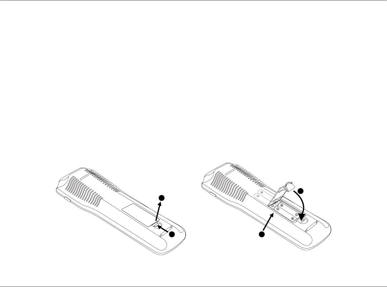
REMOTE CONTROL BATTERY INSTALLATION
The remote control requires four AAA batteries. The batteries should be replaced as needed. Alkaline batteries, which last longer without
leaking, are recommended. When battery power is low, the remote control enters a low-voltage condition, preventing it from operating the
RV-5. When this occurs, replace the batteries. Normal operation will resume when new batteries are installed.
To replace the remote control batteries:
1. Locate the battery compartment on the back of the remote control. Press the tab (1) and lift the cover (2) away from the remote control.
2. Remove old batteries (if applicable).
3. Observing the proper polarity, insert four AAA batteries (3).
4. Align the cover over the battery compartment and gently press down until it snaps back into place (4).
5. Dispose of the old batteries (if applicable).
1
2
3
4

2
Basic Operation
Front-Panel Overview ................................................................. 2-2
Rear-Panel Overview................................................................... 2-6
Tuner Overview ........................................................................ 2-10
Selecting a Station...................................................................................2-10
Direct Station Access ...............................................................................2-10
Tune/Seek Access ....................................................................................2-10
Scan Mode ..............................................................................................2-11
Loading Presets .......................................................................................2-11
Saving Presets..........................................................................................2-11
Editing Presets .........................................................................................2-12
Autoload .................................................................................................2-12
Amplifier Overview ................................................................... 2-12
Amplifier Channel Status .........................................................................2-13
Making Connections With the Amplifier Output ......................................2-13
Headphone Overview ............................................................... 2-13
Remote Control Overview......................................................... 2-14
Operation Considerations........................................................................2-14
MAIN Menu ............................................................................................2-14
Menu Navigation ....................................................................................2-14
Menu Item Selection ...............................................................................2-15
Remote Control Buttons ..........................................................................2-17
Command Matrix....................................................................................2-18
Understanding the Zones ......................................................... 2-28
Two-Line Status ........................................................................ 2-28
STATUS Menus ......................................................................... 2-29
STATUS Menu Parameter Descriptions.....................................................2-34
STATUS Menu Level Meters ...................................................... 2-35
Basic Operation Lexicon
2-2
FRONT-PANEL OVERVIEW
The RV-5 is shown below. The numbers in the front-panel illustrations correspond with the numbered items in the text.
1. Front Panel Display
2. IR Receiver
3. Volume Knob
4. Tuner
5. Main Zone Input Selection Buttons
6. Zone 2 Input Selection Buttons
7. Zone 2 Off Button
8. Main Zone Off Button
9. Mute Button
10. Mode and Buttons
11. Standby Button
8
7
1234
5
6
10 9
11

RV-5 Basic Operation
2-3
1 FRONT-PANEL DISPLAY
Use the front-panel display to view the current input, listening
mode, input source and volume level. If the built-in tuner is active,
the display will show the frequency, band, listening mode and
volume level. The 2 x 20 character display also functions as a display
for messages and menus, one line at a time.
Note:
Power is still supplied to the RV-5 when standby mode is activated.
2 IR RECEIVER
The IR receiver receives infrared commands from the RV-5 remote
control. There are three associated LEDs.
• The amber LED blinks when a remote control command is
received.
• The red LED lights when the A/D converters are overloading.
• The blue LED lights when the RV-5 is powered on and activated
– even if the FRONT PANEL DISPLAY menu STATUS parameter is
set to ALWAYS OFF.
3 VOLUME KNOB
Use the volume knob to adjust volume level in all Zones.
To adjust the Main Zone volume level:
Rotate the volume knob clockwise to increase
or counterclockwise to decrease volume level
in 1dB increments. A horizontal bar graph
indicating the current Main Zone volume level is displayed in the
on-screen and front-panel displays. The Main Zone volume range is
–80 to +12dB.
To adjust the Zone 2 volume level:
1. Press and hold the front-panel Zone 2 input selection button that
corresponds with the current input source. For instance, if the
current input source is using the DVD1 input, press and hold the
DVD1 input selection button in the desired zone.
2. While holding the desired zone input
selection button, rotate the volume knob
clockwise to increase or counterclockwise to
decrease volume level in 1dB increments.
The corresponding horizontal graph
appears in the on-screen and front-panel
displays, and indicates the position at which the current Zone 2
volume level falls within the –80 to +12dB volume range.
3. Release the selected Zone 2 input selection button when Zone 2
volume level has been set.
4 TUNER SELECTION BUTTONS
Tuner selection buttons allow for direct entry of station frequencies,
selection of AM or FM broadcast bands and the saving/recalling of
presets. See “Tuner Overview” on page 2-9 for additional
information.
Amber LED
Red LED
Blue LED
VOLUME -34db
ZONE 2 VOLUME -34db
ZONE 3 VOLUME -34db

Basic Operation Lexicon
2-4
FRONT-PANEL OVERVIEW (continued)
5 MAIN ZONE INPUT SELECTION BUTTONS
Selects the corresponding input in the Main Zone. When an input is
selected, a blue LED lights on the corresponding input selection
button. When the Main Zone is deactivated, pressing a Main Zone
input selection button activates the corresponding input in the
Main Zone. Zone 2 remains deactivated until a Zone 2 input is
selected.
6 ZONE 2 INPUT SELECTION BUTTONS
Selects the corresponding input in Zone 2. When an input is
selected, an amber LED lights on the corresponding input selection
button. When Zone 2 is deactivated, pressing a Zone 2 input
selection button activates the corresponding input in Zone 2. The
Main Zone remains deactivated until a Main Zone input is selected.
7 STANDBY BUTTON
Toggles the RV-5 between on and standby. When the RV-5 is
powered on, pressing this button places the RV-5 into standby and
lights the red LED on the button. Power is supplied to the RV-5
when in standby. When the RV-5 is in standby, pressing the button
turns the unit on and activates all zones that were active in the
previous operating session.
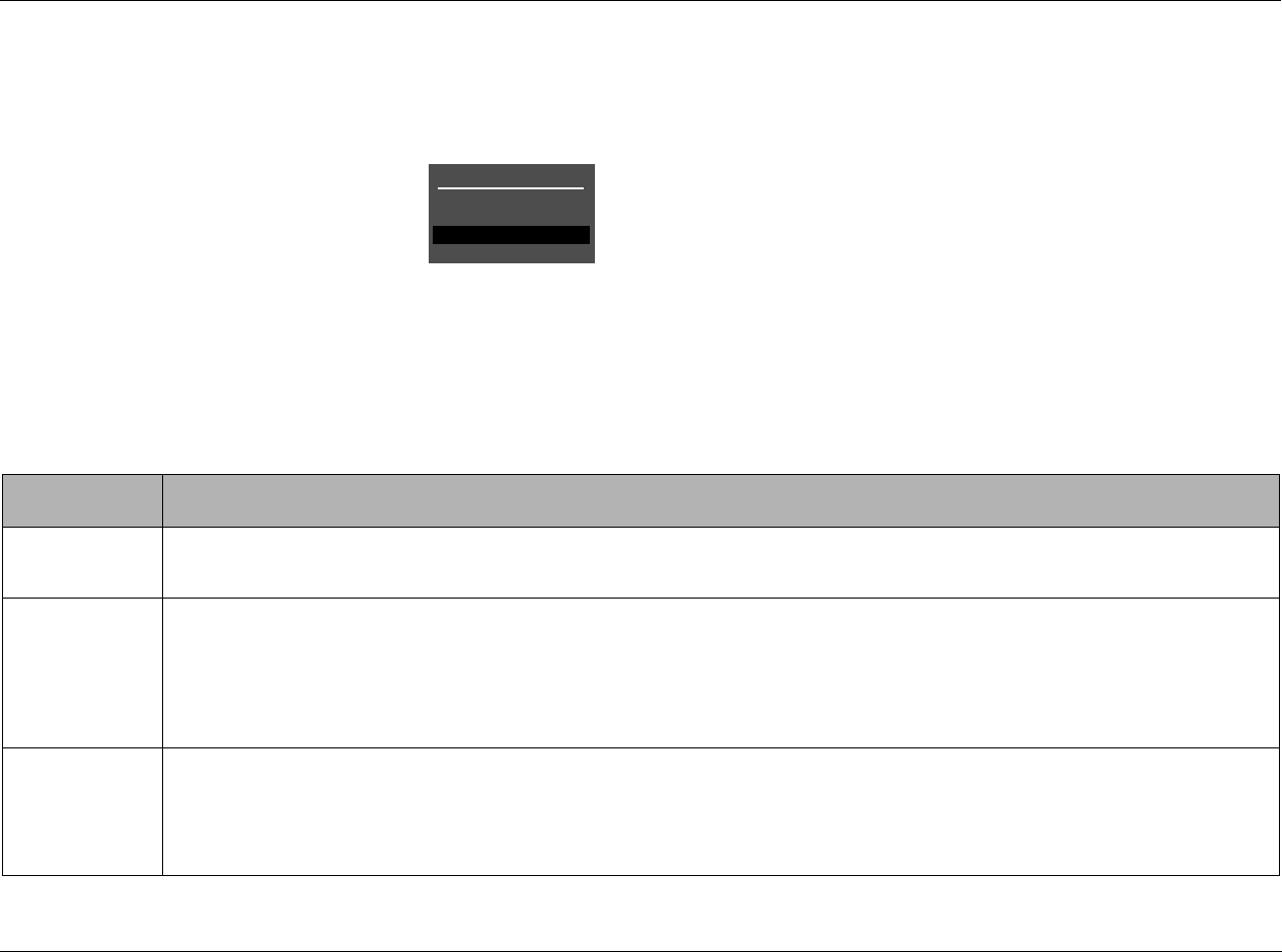
In the event of a power outage, the RV-5 will display a BROWN
OUT!! PRESS STANDBY message. To turn the unit on, use the
STANDBY button. For more information, see “POWER
MANAGEMENT” on page 3-3.
8 MODE and BUTTONS
Use the Mode buttons to scroll to the previous () or next ()
available listening mode. Scrolling occurs in the order shown in the
MODE ADJUST menu. Refer to “Listening Mode Activation” on
page 6-2 for more information.
9 MUTE BUTTON
Mutes or restores the RV-5 Main Zone volume to its original level. Press
the Mute button to mute volume level; “MUTE ON” appears in the
on-screen and front-panel displays. Press the Mute button again to
restore the volume to its original level. The VOLUME CONTROL SETUP
and MUTE LEVEL parameter can be used to set mute levels.
Mute may be activated automatically or manually. For example, the
RV-5 briefly activates mute when changing input sources or
listening modes. The amber Mute button LED lights whenever
mute is activated.
10 MAIN ZONE OFF BUTTON
Deactivates the Main Zone.
11 ZONE 2 OFF BUTTON
Deactivates Zone 2.
Basic Operation Lexicon
2-5
REAR-PANEL OVERVIEW
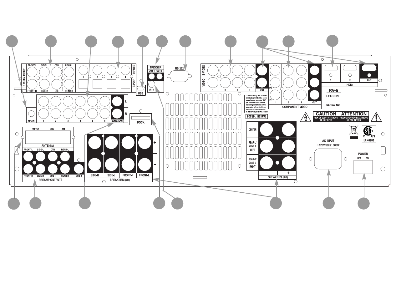
The RV-5 rear panel is shown below. The numbers in the rear-panel illustrations correspond with the numbered items in the text.
1. Microphone Input Connectors
2. Analog Audio Input Connectors
3. Main Zone Audio Output Connectors
4. Digital Input Connectors
5. USB Connector Port
6. Trigger Output Connectors
7. RS-232 Connector
8. Video Input Connectors
9. Main Zone Video Ouput Connectors
10. Component Video Input Connectors
11. HDMI Input Connectors
12. Power Switch
13. AC Input Connector
14. Amplifier Outputs
15. IR In Connector
16. Dock Connector
17. Zone 2 Digital Audio Output Connectors
18. Preamplifier Outputs
19. Tuner Antenna Connectors
2
5
4
136 7 8
9
10
13
19 14
16
18
11
12
15
17

Basic Operation Lexicon
2-6
REAR-PANEL OVERVIEW (continued)
CAUTION! Never make or break connections to the RV-5
unless the RV-5 and all associated components are
powered off.
1 MICROPHONE INPUT CONNECTOR
Provides a microphone input for speaker calibration.
2 ANALOG AUDIO INPUT CONNECTORS
Provides analog audio inputs. Eight connectors labeled Front L/R,
Center, LFE, Side L/R and Rear L/R are available.
3 MAIN ZONE AUDIO OUTPUT CONNECTORS
Provides analog audio outputs in the Main Zone. Six stereo analog
audio input connectors labeled 1 to 6 are available.
4 DIGITAL AUDIO INPUT CONNECTORS
Provides digital audio input in the Main Zone. Four S/PDIF coaxial
and four S/PDIF optical (Toslink) input connectors are available.
Connectors are compatible with PCM (44.1, 48, 88.2 and 96kHz),
Dolby Digital, and DTS(-ES) sources. Connectors are not compatible
with MPEG (MP3) sources.
5 USB CONNECTOR PORT
Provides a USB port to connect to a compatible computer running
Windows® 2000, Windows® XP, or higher with the latest service
packs installed to listen to audio from the computer through the RV-
5. The USB connector port is a “Mini B” connector and can also be
used to connect a compatible computer to the RV-5 for firmware
upgrades, when available. See page xxxx for more information on
playback of computer audio.
6 TRIGGER OUTPUT CONNECTORS
Provide 12V DC output to control connected components. Two
trigger output connectors are available on a removable terminal
block. The PWR connector (the power trigger output connector) is
not configurable. It is activated when the RV-5 is powered on, and
deactivated when the RV-5 is powered off from the rear panel or by
putting the RV-5 into standby. The trigger output connector
(labeled 1) can be configured for remote or program operation. See
“Trigger Setup” on page 3-70 for more information.
7 RS-232 CONNECTOR
The RS-232 serial connector provides serial control and is used to
perform configuration downloads and flash memory software
upgrades.
8 VIDEO INPUT CONNECTORS
Provides the Main Zone video inputs. Four composite video
connectors labeled 1 to 4 and four S-Video connectors labeled 1 to
4 are available.

RV-5 Basic Operation
2-7
9 MAIN ZONE VIDEO OUTPUT CONNECTORS
Provides the Main Zone video outputs. One composite video
connector, one S-Video connector, one component video
connector, and one HDMI video connector are available.
10 COMPONENT VIDEO INPUT CONNECTORS
Provides inputs that can be used with any source device that is
equipped with analog Y/Pr/Pb or RGB component video outputs.
Three inputs, labeled Component Video 1 to 3, are supplied.
11 HDMI INPUT CONNECTORS
Provides two HDMI inputs for devices such as DVD player or HDTV
tuner.
12 POWER SWITCH
Use the Power switch to connect or disconnect power from the AC
Input connector to the RV-5. The I and O positions represent “on”
and “off” status, respectively. When the RV-5 is powered on, the
front-panel Standby button or remote control On button can be
used to activate and deactivate standby mode. When the RV-5 is
powered off, standby mode is not available.
In the event of a power outage, the RV-5 will display a BROWNOUT,
CYCLE POWER message. To turn the unit back on, use the rear-
panel power switch. In this instance, the front-panel StandBy switch
has no effect.
13 AC INPUT CONNECTOR
Provides power to the RV-5 through the supplied power cord.
14 AMPLIFIER OUTPUTS
Provide audio outputs to the speakers. Channels are labeled for
Front, Center, and Rear speakers to facilitate surround system setup.
Normally, the REAR Left & RIGHT speakers are used in the Main
Zone for 7.1 surround sound systems, but they can also be used as
the left and right outputs for Zone 2.
The amplifier binding posts accommodate the following
connectors:
• standard 0.75-inch banana plugs
• size 10-12 gauge spade connectors
• up to 10-gauge bare wire
See the next page for additional amplifier information.
15 IR IN CONNECTOR
Accepts input of IR signals from infrared distribution equipment.
One 3.5mm jack that accepts a stereo plug (Tip/Ring/Sleeve
connection) or mono plug (Tip/Sleeve connection) is available.

Basic Operation Lexicon
2-8
REAR-PANEL OVERVIEW (continued)
16 DOCK CONNECTOR
Provides an input port for an iPod®, which can then be accessed
through the RV-5. To use this feature, the D-1 Dock option must be
installed to the DOCK connector. With a compatible iPod
connected to the RV-5, selecting the DOCK input allows you to play
audio programming from the iPod. You can navigate the iPod
using the RV-5 remote and view any of the iPod menus through the
RV-5 front panel and any video monitor connected to the RV-5.
For more information on the D-1 Dock option and how to use your
RV-5 with an iPod, refer to page xxx.
17 ZONE 2 DIGITAL AUDIO OUTPUT CONNECTORS
Provides digital audio output in Zone 2. Two outputs are available,
marked LEFT and RIGHT.
18 PREAMPLIFIER OUTPUTS
Provides outputs for an optional, external power amplifier for appli-
cations where higher power is desired.
19 TUNER ANTENNA CONNECTORS
Provides two antenna connections for the AM/FM stereo radio
tuner.
AMPLIFIER OVERVIEW
The RV-5 features a 9-channel power amplifier with 140W per
channel. Heavy duty gold plated 5-way binding posts are provided
for speaker connections.
The amplifiers feature advanced thermal current and DC protection
for each channel. Thermal protection monitors the temperature of
the chassis and heatsinks and automatically deactivates the specific
channel(s) when they exceed their normal safe operating temper-
ature. Current protection ensures that the output transistors are
protected by limiting the current capability which is determined by
the output voltage, while DC protection prevents DC and
frequencies below 10Hz from reaching the speakers.
The amplifiers are designed to meet the highest standards of perfor-
mance and sound quality.
MAKING CONNECTIONS WITH THE AMPLIFIER
OUTPUT
The amplifier output connectors can accept bare speaker wires,
banana plug connectors or certain spade connectors. When using
bare speaker wires, loosen the connector, insert the wire into the
top of the receptacle, then tighten the connector. The same
procedure should be used for spade connectors. Banana plugs
should be inserted into the outward-facing receptacle.
Use heavy-gauge speaker cable to ensure low-impedance
connections between the amplifier and the speakers. Observe
correct speaker polarity.
CAUTION! Do not connect the outputs of one channel to
the outputs of other channels or to other amplifiers.

RV-5 Basic Operation
2-9
TUNER OVERVIEW
The RV-5 features an AM/FM stereo radio tuner. The front panel
displays the currently selected frequency, band, listening mode and
volume. Forty presets can store AM or FM frequencies, identified by
the preset number/name and station frequency/band. For example:
WABC/90.90 FM or Preset 02/10.30 AM. Two antennas are
supplied with the RV-5: one for AM and one for FM stereo. At a
minimum, use of the supplied antennas is recommended to ensure
consistent tuner performance.
The tuner can be setup to receive elements of the Radio Data
System (RDS) broadcasts. Originated in Europe and now with
limited availability in the US, the RDS is a standard for broadcasting
digital data along with an FM radio broadcast. When the RDS
option is active and RDS data is received, the RV-5 tuner displays
the identity of the broadcast station, receipt of alternate station
frequencies and any additional text (referred to as RT or Radio Text)
that the station broadcasts. For more information on RDS features,
see “Tuner Setup” on page 3-72.
SELECTING A STATION
Begin selecting a radio station by activating the built-in tuner input.
To activate the tuner input, press the front-panel TUNER button or
select the TUNER option from the remote-control MAIN screen. See
the “Tuner Setup” on page 3-72 for more information.
Next, determine if the desired frequency band is active by pushing the
front-panel or remote-control AM/FM button to toggle between the
AM and FM frequency bands.
Once the frequency band is set, there are several ways to select a radio
station: direct station access, tune/seek access, scan mode and presets.
DIRECT STATION ACCESS
To access a specific frequency, use the numeric buttons on either the
front panel or remote control to enter the desired station frequency.
To directly access a station from the front panel or remote control:
1. Press the AM/FM button to select the desired band.
2. Enter the three or four digit station frequency. For example, to
load FM station 90.9, press 9-0-9. To load AM station 1030, press
the AM/FM button to select the AM band, then press 1-0-3-0.
Note:
When digits are first entered, a “Loading Preset” status message appears
in the front-panel (and on-screen) display. When a third digit is entered,
the RV-5 senses a frequency is being entered and changes the status
message to “Setting Frequency.”
TUNE/SEEK ACCESS
Press one of the Tune/Seek buttons on the front panel (/) or
remote control ( /) to navigate to the next available
frequency. For example, if the currently loaded frequency is
101.7FM, press the Tune/Seek button to load 101.9FM. Press the
Tune/Seek button again to load 102.1FM, and so on.
Press one of the Tune/Seek buttons on the front panel (/) or
remote control ( /) for 2 seconds to activate seek mode.
Seek mode searches for the next available radio station. If the tuner
is having difficulty locating stations, raise the sensitivity level. See
“SCAN SENS” on 3-73 for more information.

Basic Operation Lexicon
2-10
TUNER OVERVIEW (continued)
SCAN MODE
Scan Mode scans through all available stations, pausing for two
seconds on each station before scanning to the next one.
To enter Scan Mode:
Press and hold the front-panel (/) or remote-control ( /)
Tune/Seek buttons until SCAN or SCAN is displayed.
To stop scanning:
Press either Tune/Seek button.
LOADING PRESETS
To load a preset:
Enter a preset (number between 1 and 40) using the front-panel or
remote-control number buttons.
A “Loading Preset” status message appears in the front-panel (and
on-screen) display. If a third digit is entered, the tuner switches over
to Direct Station Access mode and the front-panel status message
changes to “Setting Frequency.”
To skip through available presets in order:
Press the remote-control or button. For example, if preset 1 is
loaded and the button is pressed, the RV-5 will load preset 2 (or
the next available preset). If preset 1 is loaded and the button is
pressed, the RV-5 will load preset 40 (or the next available preset).
Note:
This feature is only accessible via the remote control.
SAVING PRESETS
The RV-5 has 40 presets available for storing AM or FM stations. The
presets are divided into four banks with ten presets per bank. It is
possible to store a combination of AM and FM stations in each
bank. Storing presets on the RV-5 can be accomplished from either
the front panel or the remote control. The operation is identical.
To save a station as a preset on the RV-5:
1. Press the front-panel or remote-control SAVE button. A status
message displaying ”Saving Preset” appears in the front-panel
(and on-screen) display.
2. Enter a number between 1 and 40 to save the currently loaded
frequency as the corresponding preset.
For example, if the tuner is currently playing 101.7FM, press
the SAVE button, then the 1 button to save 101.7FM as preset
number 1.
Press the 1 button followed by the 5 button to save as preset
number 15. Pressing more than two numbers resets the preset
number to the third digit entered.
Pressing the SAVE button a second time cancels the saving process.
NAMING PRESETS
Preset stations use a naming system based on the RDS system. In the
US, each preset channel is identified by the station's call letters, or what
the broadcast information identifies as the call letters. In Europe and
Japan, each preset channel is identified by the station's Program

RV-5 Basic Operation
2-11
Service (PS) name.
If the RDS information is not available, the preset name defaults to
PresetXX, where XX is the listed number position in the Preset menu.
For example, if Preset #01 is FM 90.90 and the call letters are WABC,
then the name for that position is WABC. If Preset #23 does not
broadcast their call letters, then that location is identified as Preset23 in
the menu.
EDITING PRESETS
It is possible to customize the name of each preset on the RV-5.
To edit the preset name:
1. Select TUNER PRESETS from the MAIN MENU. The TUNER
PRESETS menu contains a list of preset pages. PAGE 1 contains
presets 1 through 10, PAGE 2 contains presets 11 through 20, etc.
2. Select the page containing the desired preset.
A list of presets appears.
3. Select the desired preset.
The EDIT PRESET menu opens and displays the preset call letters
(or PS), frequency, and band.
The EDIT PRESET menu options are as follows:
• Select LISTEN TO PRESET to load the preset frequency.
• Select NAME to customize the preset name. The preset name
can be up to eight characters long.
• Select CLEAR PRESET to clear the frequency and band informa-
tion from the preset.
See “Tuner Presets” on page 5-2 for additional information.
AUTOLOAD
The RV-5 can automatically scan and store presets. This can be
accomplished only from the remote control. See “Tuner Setup
(continued)” on page 3-74 for additional information.
To start autoloading:
1. Select AUTOLOAD from the MAIN MENU : SETUP : TUNER SETUP
menu.
2. Press menu to start AUTOLOAD.

Basic Operation Lexicon
2-12
REMOTE CONTROL OVERVIEW
The RV-5 remote control provides full operation of the RV-5,
including commands, such as menu navigation, that are not
available from the front panel. It is also designed to provide control
for the entire home theater system. This section provides a brief
overview of the remote control. For detailed operation/
programming instructions and manufacturing codes, refer to
Appendix C.
OPERATION CONSIDERATIONS
The following factors can improve or impede remote control
operation.
Note the following before operating the RV-5 remote control:
• The remote control must be in line-of-sight with the front-panel
IR receiver. Eliminate obstructions between the remote control
and the IR receiver. The remote control may become unreliable
if strong sunlight or fluorescent light shines on the IR receiver.
• For optimal performance, position the remote control at a
30-degree angle no more than 40 to 60 feet (12.2m to 18.3m)
from the RV-5. Placing the RV-5 inside a smoked glass cabinet
will reduce the remote control range.
• Remote controls for different components can interfere with
one another. Avoid using remote controls for different compo-
nents at the same time.
• Remote-control batteries should be replaced as needed.
RV-5 Basic Operation
2-13
MAIN MENU
Use the MAIN MENU to open the four main
menu branches: MODE ADJUST, AUDIO
CONTROLS, TUNER PRESETS and SETUP.
MENU NAVIGATION
Use the remote-control arrow buttons to navigate the extensive
menu structure starting on page B-2. The table below indicates the
navigation commands that the remote-control buttons perform
when the Main Zone command bank is activated.
Note:
The DVD1 device has been preprogrammed to control the Lexicon RT-10
and RT-20 disc players.
MENU ITEM SELECTION
Use the remote-control Menu arrows to navigate menus and to
select menu items.
To select a menu item on the open menu:
1. Press the remote-control and arrows to highlight the desired
menu item.
2. When the desired menu item is highlighted, press the Menu
MAIN MENU
MODE ADJUST
AUDIO CONTROLS
TUNER PRESETS
SETUP
Arrow Navigation Functions
• When a menu is open, press the remote-control Menu arrow to select the highlighted menu item.
• When no menus are open, press the Menu arrow to open the MAIN MENU.
• When a menu is open, press the Menu arrow to close the menu and, in most cases, open the previous menu. Subse-
quent presses continue to close the current menu and open the previous menu until the MAIN MENU is closed. When
the MAIN MENU is closed, the menu structure is also closed.
• When no menus are open, pressing the Menu arrow button performs no function.
• When a drop-down menu is open, press the Menu arrow to select the current setting and close the drop-down menu.
• When a menu is open, press the Menu and arrow buttons to scroll upward and downward through the complete list
of menu items. The highlighted menu item appears in the front-panel display. All menu items appear in the on-screen
display. A scroll bar appears in the left side of the on-screen display when menu items exceed the on-screen display’s top
and bottom margins. The cursor automatically wraps to the next menu item when the first or last menu item is passed.
Basic Operation Lexicon
2-14
MENU OPTIONS
Selecting a menu option opens another menu within the menu
structure. For example, selecting SETUP from the MAIN MENU opens
the SETUP menu.
PARAMETER DROP-DOWN MENUS
Selecting some menu options opens a drop-down menu that contains
a list of available parameter settings. For example, selecting the
CUSTOM NAME parameter from the DISPLAY SETUP menu opens a
drop-down menu which is used to select the ON or OFF setting.
To select a setting in a parameter drop-down menu:
1. When the drop-down menu opens, press the remote-control
and arrows to scroll upward and downward through the
complete list of available settings. The current setting is displayed
beneath the parameter name in the on-screen and front-panel
displays.
2. When the desired setting appears beneath the parameter
name, press the arrow to accept the setting and close the
drop-down menu.
HORIZONTAL BAR GRAPHS
Selecting some menu parameters opens a horizontal bar graph. The
bar graph indicates the position at which the current parameter setting
falls within the entire parameter range.
For example, selecting the A/V SYNC DELAY parameter from the
DISPLAY SETUP menu opens the horizontal bar graph shown below,
which is used to adjust the amount of audio delay.
To adjust a parameter setting with a horizontal bar graph:
1. When the horizontal bar graph appears, press the remote-control
and arrows to increase or decrease the setting in the desig-
nated increments. The setting appears to the right of the
parameter name in the on-screen and front-panel displays.
2. When the desired adjustments have been made, press the
arrow to select the setting and close the horizontal bar graph.
Note:
Menu item selection instructions differ for certain menus. These instances
are noted throughout this user guide.
SETUP
INPUTS
SPEAKERS
I/O CONFIG
DISPLAYS
VOLUME CONTROLS
TRIGGER
TUNER SETUP
LOCK OPTIONS
MAIN MENU
MODE ADJUST
AUDIO CONTROLS
TUNER PRESETS
SETUP
LIVE! CALIBRATION
POWER MANAGEMENT
DISPLAY SETUP
ON-SCREEN DISPLAY
FRONT PANEL DISPLAY
A/V SYNC DELAY
CUSTOM NAME
EDIT CUSTOM NAME
ON
OFF
OFF
OFF
A/V SYNC DELAY OFF
CUSTOM NAME OFF
OFF, 1 to 60ms
DISPLAY SETUP
ON-SCREEN DISPLAY
FRONT PANEL DISPLAY
A/V SYNC DELAY
CUSTOM NAME
EDIT CUSTOM NAME
OFF
OFF
RV-5 Basic Operation
2-15
COMMAND MATRIX
The command matrix describes the commands that the remote
control buttons perform when each command bank is active.
2
1
3
4
5
6
7
8
BUTTON HOME MAIN PAGE1 MAIN PAGE2 ZONE2 PAGE1 ZONE2 PAGE2
1Enters RV-5 standby mode.
2Activates the RV-5.
3Displays the MAIN Zone
command bank, which
includes commands
that control the Main
Zone.
Displays the
Main Zone
Status.
Selects the Dolby
Digital listening
mode family.
Displays the Zone 2
Status.
Toggles RV8 between
5 speaker and 7
speaker modes.
4Displays the Zone 2
command bank, which
includes commands that
control Zone 2.
Deactivates the
Main Zone.
Selects the DTS
listening mode
family.
Deactivates Zone 2. Adjusts the AUDIO
CONTROLS menu
Main Zone BALANCE
to the left.
5Displays the Zone 3
command bank, which
includes commands that
control Zone 3.
Selects the Tuner
input for the
Main Zone.
Selects the THX
listening mode
family.
Selects the Tuner
input for Zone 2.
Sets the Main Zone
Volume level to
-15dB.
6Displays the DVD1
command bank, which
includes commands that
control DVD1.
Selects the
DVD1 input for
the Main Zone.
Toggles between
the current
listening mode
and the 2-
CHANNEL
listening mode.
Selects the DVD1
input for Zone 2.
Shows status menu
for current Main Zone
input stream.
STAT2 button: see
page 2-28 for more
information.
7Displays the DVD2
command bank, which
includes commands that
control DVD2.
Selects the
DVD2 input for
the Main Zone.
Analog Bypass
Toggle.
Selects the DVD1
input for Zone 2.
Activates the RV-5.
Basic Operation Lexicon
2-16
8Displays the SAT
command bank, which
includes commands that
control the Satellite box.
Selects the SAT
input for the
Main Zone.
Selects the L7 FILM
listening mode.
Selects the
Satellite input for
Zone 2.
Reserved for future
expansion.
BUTTON HOME MAIN PAGE1 MAIN PAGE2 ZONE2 PAGE1 ZONE2 PAGE2
RV-5 Basic Operation
2-17
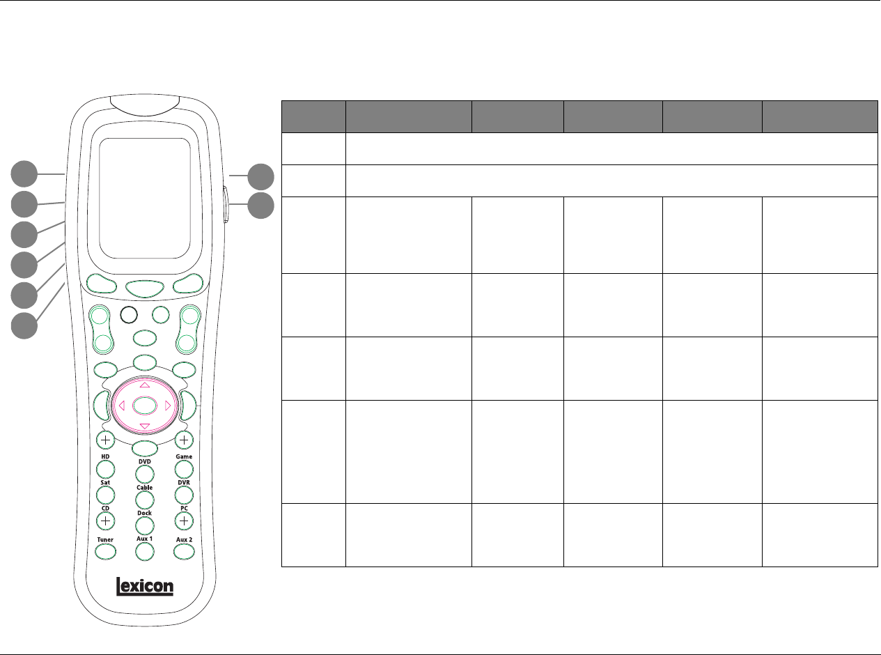
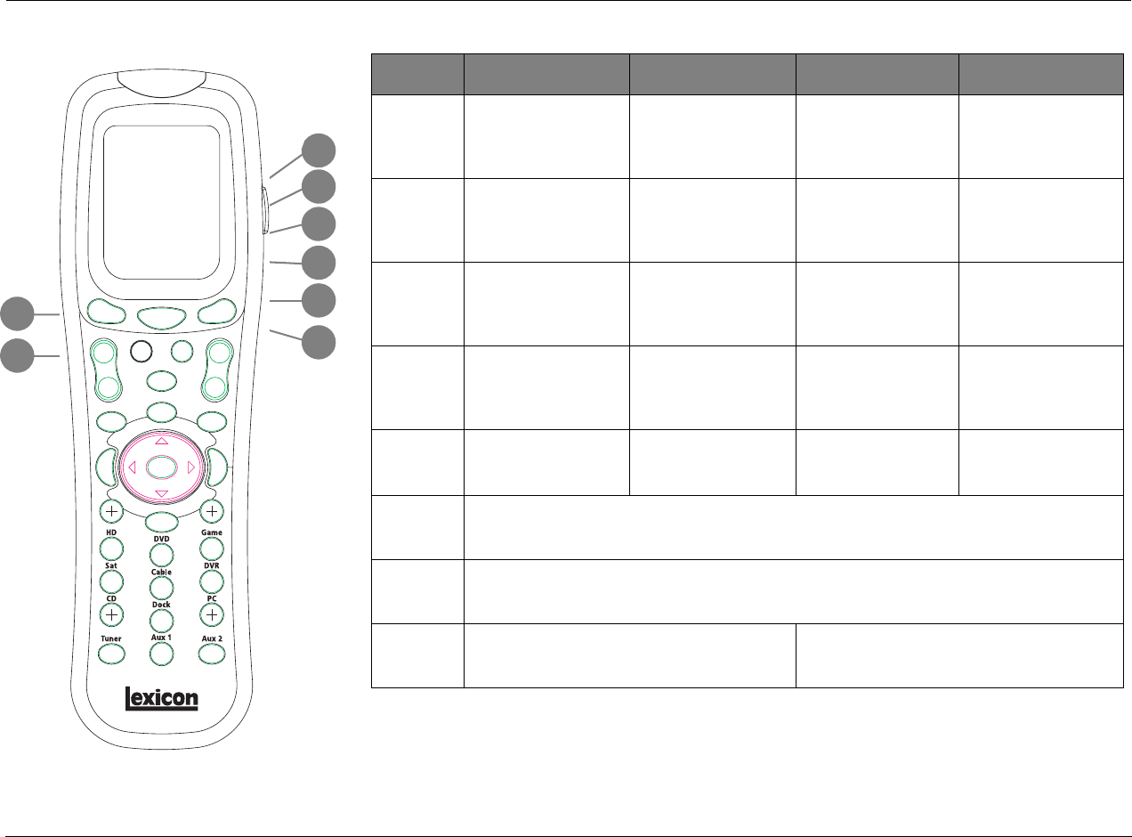
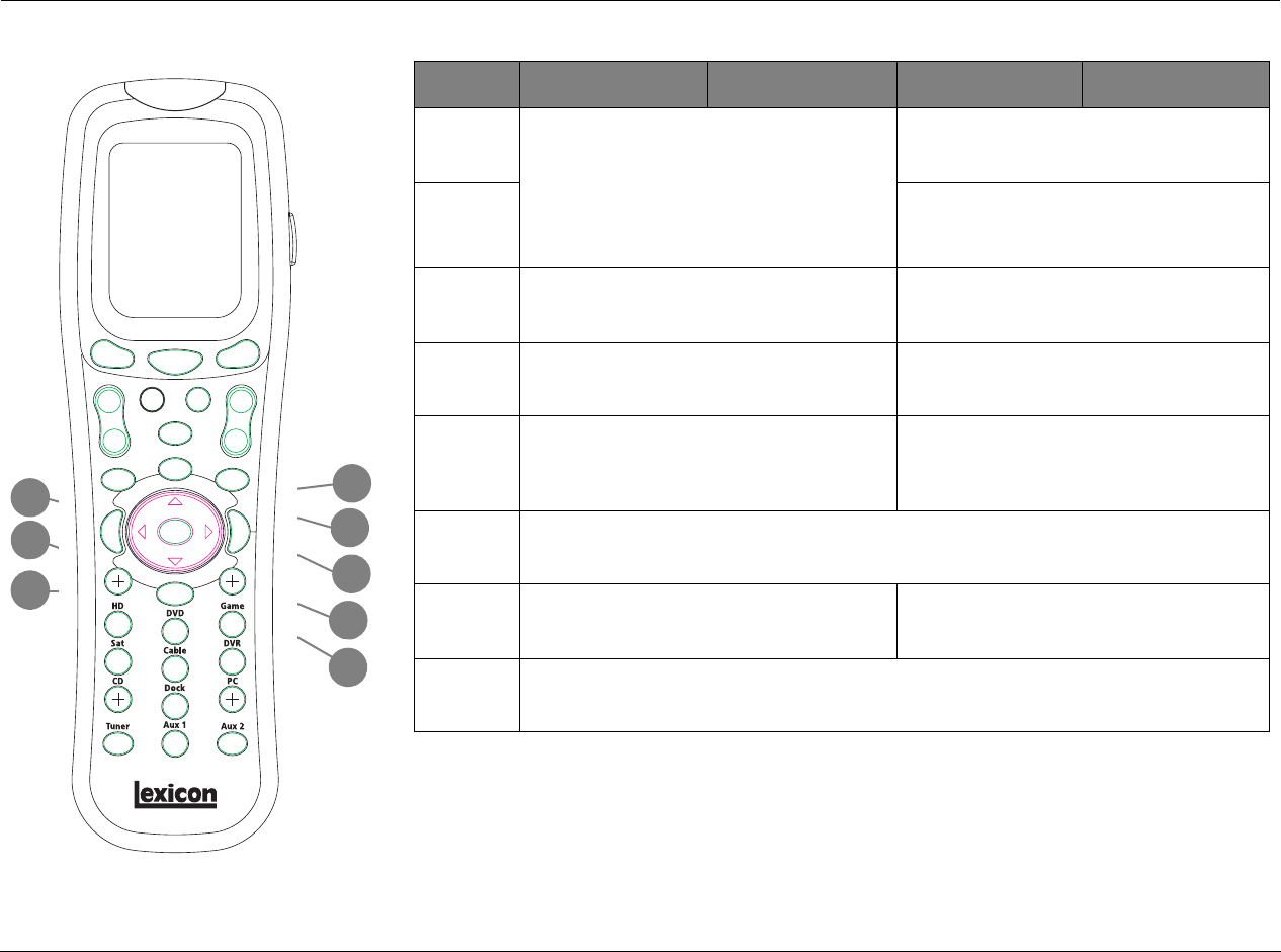
REMOTE CONTROL BUTTONS
1. SYSTEM POWER OFF
2. Displays the name of the selected device.
3. POWER ON
4. Device and function buttons
5. Light
6. Displays page number/currently selected device
7. LCD page change
8. FAVORITE
9. HOME menu
10. CHANNEL/Listening Mode (+/-)
11. Previous channel
12. VOLUME (+/-)
13. MUTE
14. TRANSPORT functions (PLAY, STOP, REWIND, PAUSE, REC, SKIP and FF)
for VCR, DVD and CD
15. JOYSTICK (left, right, up, down and center press)
16. DISPLAY/AM/FM
17. ENTER/SAVE
18. MACRO buttons
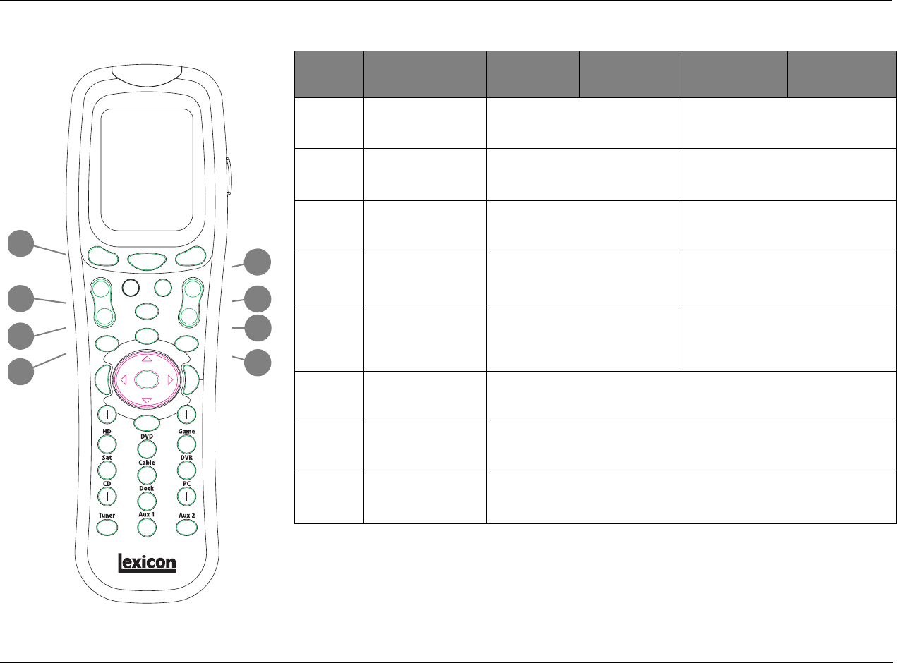
3
1
4
5
18
16
15
13
12
6
7
11
2
4
8
9
10
14
17
Basic Operation Lexicon
2-18
* History-dependent buttons perform different functions, depending on the Zone or device that is currently being controlled.
Check the bottom of the LCD for the currently controlled device.
BUTTON HOME MAIN
PAGE1 MAIN PAGE2 ZONE2 PAGE1 ZONE2 PAGE2
9Selects the VCR
command bank, which
includes commands
that control the VCR.
Selects the VCR
input for the
Main Zone.
Selects the L7
Music listening
mode.
Selects the VCR
input for Zone 2.
Adjusts the Audio
Controls menu Main
Zone BALANCE
parameter to the
right.
10 Selects the TV
command bank, which
includes commands
that control the TV.
Selects the TV
input for the
Main Zone.
Selects the L7 TV
listening mode.
Selects the TV input
for Zone 2.
Sets the Main Zone
volume level to
-30dB.
11 Selects the CD
command bank, which
includes commands
that control the CD
player.
Selects the CD
input for the
Main Zone.
Selects the L7
Music Surround
listening mode.
Selects the CD
input for Zone 2.
Toggles the Setup
ON SCREEN
DISPLAY parameter.
12 Selects the Phono
command bank, which
includes commands
that control the
associated device.
Selects the
Phono input for
the Main Zone.
Toggles between
setting the input
to auto, analog or
digital.
Selects the Phono
input for Zone 2.
Deactivates the RV-5.
13 N/A Selects Page 2 of
the Main Zone
command bank.
Selects Page 1 of
the Main Zone
command bank.
Selects Page 2 of
the Zone 2
command bank.
Selects Page 1 of the
Zone 2 command
bank.
14 Selects the Home command bank.
15 Scrolls through Favorite Channel pages.
16 History-dependent* Increases the Main Zone volume level
in 1dB increments.
Increases the Zone 2 volume level in 1dB
increments.
9
13
16
10
11
12
14
15
RV-5 Basic Operation
2-19
2
1
3
4
5
6
7
8
BUTTON ZONE3 PAGE1 ZONE3 PAGE2 DVD1 PAGE1 DVD1 PAGE2
1Enters RV-5 standby mode. Reserved for future expansion.
2Activates the RV-5. Toggles RT-10 or RT-20 power.
3Displays the Status of
Zone 3.
Resets the AUDIO
CONTROLS menu BASS,
TREBLE, and TILT EQ
parameter to +0.0dB.
Opens and closes the RT-10 or RT-20 disc tray.
4Deactivates Zone 3. Decreases the AUDIO
CONTROLS menu Main
Zone BASS parameter
in.5dB increments.
Opens the RT-10 or
RT-20 Top menu.
Opens and closes the
RT-10 or RT-20 Video
Adjust bar.
5Selects the TUNER input
for Zone 3.
Decreases the AUDIO
CONTROLS menu Main
Zone TREBLE parameter
in.5dB increments.
Activates RT-10 or
RT-20 random
playback.
Opens the RT-10 or
RT-20 Angle bar.
6Selects the DVD1 input
for Zone 3.
Decreases the AUDIO
CONTROLS menu Main
Zone TILT EQ parameter
in.2dB increments.
Activates RT-10 or
RT-20 repeat playback.
Activates the RT-10 or
RT-20 condition
memory mode.
7Selects the DVD2 input
for Zone 3.
Deactivates AUDIO
CONTROLS menu Main
Zone LOUDNESS
parameter.
Activates RT-10 or
RT-20 A-B repeat
playback.
Activates the RT-10 or
RT-20 last memory
playback.
8Selects the Satellite
input for Zone 3.
Reserved for future
expansion.
Opens the RT-10 or
RT-20 Setup menu.
Creates up to five
shortcuts for frequently
adjusted RT-10 or RT-20
Setup menu parameters.
Basic Operation Lexicon
2-20
BUTTON ZONE3 PAGE1 ZONE3 PAGE2 DVD1 PAGE1 DVD1 PAGE2
9Selects the VCR input
for Zone 3.
Increases the AUDIO
CONTROLS menu BASS
parameter in .5dB
increments.
Closes certain Setup
menus without saving
the changes.
Activates and deacti-
vates the RT-10 or
RT-20 rear- panel video
output connectors.
10 Selects the TV input for
Zone 3.
Increases the AUDIO
CONTROLS menu
TREBLE parameter in
.5dB increments.
Activates the RT-10 or
RT-20 display mode.
Controls the brightness
of front-panel display
characters.
11 Selects the CD input for
Zone 3.
Increases the AUDIO
CONTROLS menu Main
Zone TILT EQ parameter
level in .2dB increments.
Opens the RT-10 or
RT-20 Subtitle bar.
Activates the RT-10 or
RT-20 search mode.
12 Selects the Phono input
for Zone 3.
Activates the AUDIO
CONTROLS menu Main
Zone LOUDNESS
parameter.
Opens the RT-10 or
RT-20 Audio bar.
Activates the RT-10 or
RT-20 program mode.
13 Displays Zone 3 Page 2
command bank.
Displays Zone 3 Page 1
command bank.
Displays DVD1 Page 2
command bank.
Displays DVD1 Page 1
command bank.
14 Displays the Home command bank.
15 Scrolls through Favorite Channel pages.
16 Increases Zone 3 volume level in 1dB increments Increases RV-5 Main volume level in 1dB
increments
9
13
16
10
11
12
14
15
RV-5 Basic Operation
2-21
* History-dependent buttons perform different functions, depending on the Zone or device that is currently being controlled.
Check the bottom of the LCD for the currently controlled device.
20
21
23
24
18
17
19
22
BUTTON HOME MAIN
PAGE1 MAIN PAGE2 ZONE2 PAGE1 ZONE2 PAGE2
17 History-dependent* Decreases Main Zone volume level in
1dB increments.
Decreases Zone2 volume level in 1dB
increments.
18 History-dependent* Toggles between fully muting Main
Zone volume level and restoring Main
Zone volume level to its original level.
Centers the AUDIO CONTROLS menu
BALANCE and FADER parameters.
19 History-dependent* Toggles between muting Main Zone
volume level and restoring Main Zone
volume level to its original level.
Toggles between fully muting Zone 2
volume level and restoring Zone 2 volume
level to its original level.
20 History-dependent* Scrolls upward through listening
modes.
Adjusts the AUDIO CONTROLS menu
Main Zone FADER parameter towards the
front.
21 History-dependent* Scrolls downward through listening
modes.
Adjusts the AUDIO CONTROLS menu
Main Zone FADER parameter towards the
back.
22 History-dependent* If the RV-5’s built-in tuner is the currently selected input, press to skip back to
next available preset.
23 History-dependent* Activates the Trigger output connector labeled 1.
24 History-dependent* If the RV-5’s but-in tuner is the currently selected input, press to skip forward
to next available preset.
Basic Operation Lexicon
2-22
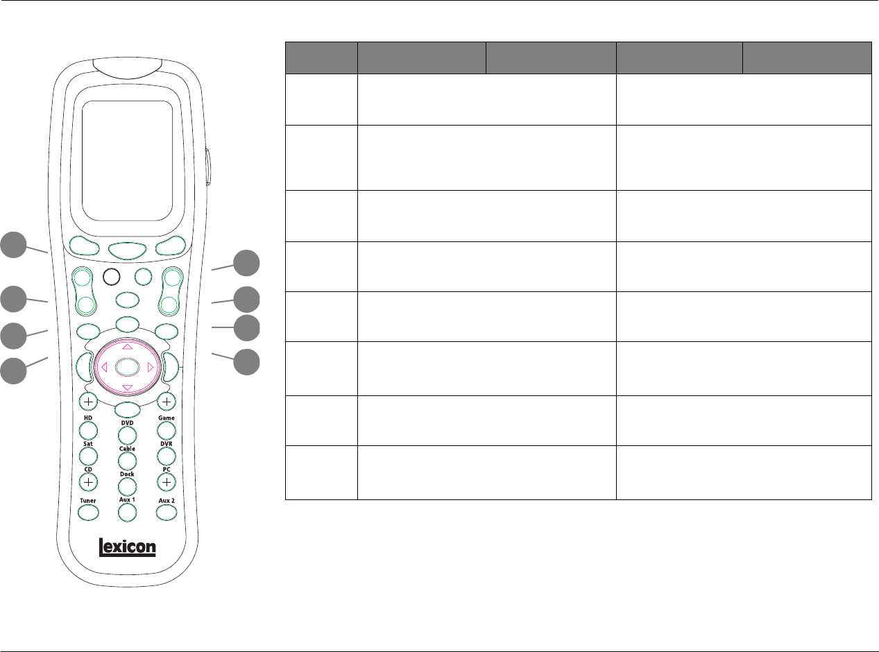
BUTTON ZONE3 PAGE1 ZONE3 PAGE2 DVD1 PAGE1 DVD1 PAGE2
17 Decreases Zone 3 volume level in.1dB increments. Decreases Main Zone volume level in.1dB
increments.
18 Activates the 5.1 THX, 5.1 THX Ultra2 or the THX
SurEX listening mode when a 5.1-channel THX
source is present. Activates Dolby PLIIx+THX when
a stereo source is present.
Toggles between fully muting the RV-5 Main Zone
volume level and restoring Main Zone volume
level to its original level.
19 Toggles between fully muting Zone 3 volume level
and restoring Zone 3 volume to its original level.
Toggles between muting the RV-5 Main Zone
volume level and restoring Main Zone volume
level to its original level.
20 Increases Subwoofer output in 1dB increments. Scrolls upward through RV-5 listening modes.
21 Decreases Subwoofer output in 1dB increments. Scrolls downward through RV-5 listening modes.
22 If the RV-5’s built-in tuner is the currently selected
input, press to skip back to the next available
preset.
Skips to the beginning of the current chapter or
track. Subsequent presses skip to the beginning of
the previous chapter or track.
23 Activates the output connector labeled Trigger 1. Activates playback of the loaded disc at regular
playback speed.
24 If the RV-5’s built-in tuner is the currently selected
input, press to skip forward to the next
available preset.
Skips to the beginning of the next chapter or
track. Subsequent presses skip to the beginning of
the next chapter or track.
20
21
23
24
18
17
19
22
RV-5 Basic Operation
2-23
* History-dependent buttons perform different functions, depending on the Zone or device that is currently being controlled.
Check the bottom of the LCD for the currently controlled device.
30
31
26
29
32
25
27
28
BUTTON HOME MAIN
PAGE1 MAIN PAGE2 ZONE2 PAGE1 ZONE2 PAGE2
25 History-dependent* If the RV-5’s built-in tuner is the currently selected input, press once to tune
to the
next available tuner frequency. Pressing for 2 seconds activates seek mode, which
searches for the next available radio station. To enter Scan Mode, press and hold
until the display shows SCAN or SCAN.
26 History-dependent*
27 History-dependent* When a DTS(-ES) source is present, toggles the ES decoding parameter,
cycling through the AUTO, ON, and OFF settings.
28 History-dependent* Deactivates the output connector labeled Trigger 1.
29 History-dependent* Activates the Dolby DIGITAL EX or Dolby DIGITAL listening mode when a
5.1- channel Dolby Digital source is present.
30 History-dependent* When a menu is open, scrolls upward through menu items.
31 History-dependent* Opens the menu structure and selects the highlighted menu item, which opens
another menu, opens a parameter drop-down menu, or selects the highlighted
parameter setting.
32 History-dependent* When a menu is open, scrolls downward through menu items.
Basic Operation Lexicon
2-24
BUTTON ZONE3 PAGE1 ZONE3 PAGE2 DVD1 PAGE1 DVD1 PAGE2
25 If the RV-5’s built-in tuner is the currently
selected input, press o nce to tune to the next
available tuner frequency. Pressing for 2 seconds
activates seek mode, which searches
for the next available radio station. To enter
Scan Mode, press and hold until the display
shows SCAN or SCAN.
When RT-10 or RT-20 playback is activated, scans
through the disc in reverse direction.
26 When RT-10 or RT-20 playback is activated, scans
through the disc in forward direction.
27 When a DTS(-ES) source is present, toggles the
ES decoding parameter, cycling through the
AUTO, ON and OFF settings.
Opens the RT-10 or RT-20 disc menu.
28 Deactivates the output connector labeled
Trigger 1.
Stops playback of the loaded disc.
29 Activates the Dolby DIGITAL EX or Dolby DIGITAL
listening mode when a 5.1-channel Dolby
Digital source is present. Activates Dolby PLIIx
Movie when a stereo source is present.
Activates RT-10 or RT-20 pause mode.
30 When a menu is open, scrolls upward through menu items.
31 Opens the menu structure and selects the
highlighted item. When no menu is open,
opens the MAIN MENU.
Navigates to the right in the RT-10 or RT-20 menu
structure.
32 When a menu is open, scrolls downward through menu items.
30
31
26
29
32
25
27
28
RV-5 Basic Operation
2-25
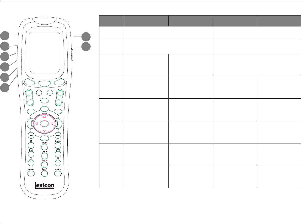
* History-dependent buttons perform different functions, depending on the Zone or device that is currently being controlled.
Check the bottom of the LCD for the currently controlled device.
34
33
39
35
37
35
36
38
BUTTON HOME MAIN
PAGE1 MAIN PAGE2 ZONE2 PAGE1 ZONE2 PAGE2
33 History-dependent* When a menu is open, closes the menu and (in most cases), opens the previous
menu. Subsequent presses continue to close the current menu and open the
previous menu until the MAIN MENU is closed. When no menus are open, shows
the two-line status.
34 History-dependent* When a menu is open, closes the menu structure. When no menus are open,
shows the 2-line status.
35 History-dependent* Numbers 0 to 9, are used to enter the frequency of radio stations or to save/load
presets when the RV-5’s built-in tuner is the currently selected input.
36 History-dependent* If the RV-5’s built-in tuner is the currently selected input, toggles between AM/FM
frequency bands.
37 History-dependent* If the RV-5’s built-in tuner is the currently selected input, pressing this button will
save the currently selected tuner frequency into a preset slot. Also use this button
when programming the remote. See page C-4 for additional information.
38 History-dependent* Macro Buttons: M1 is for Macro 1, M2 is for Macro 2 and M3 is for Macro 3. See
page C-9 for additional information on how to use and program macros.
39 History-dependent* Activates the remote control backlight that illuminates the buttons and LCD
screen for easier visibility.
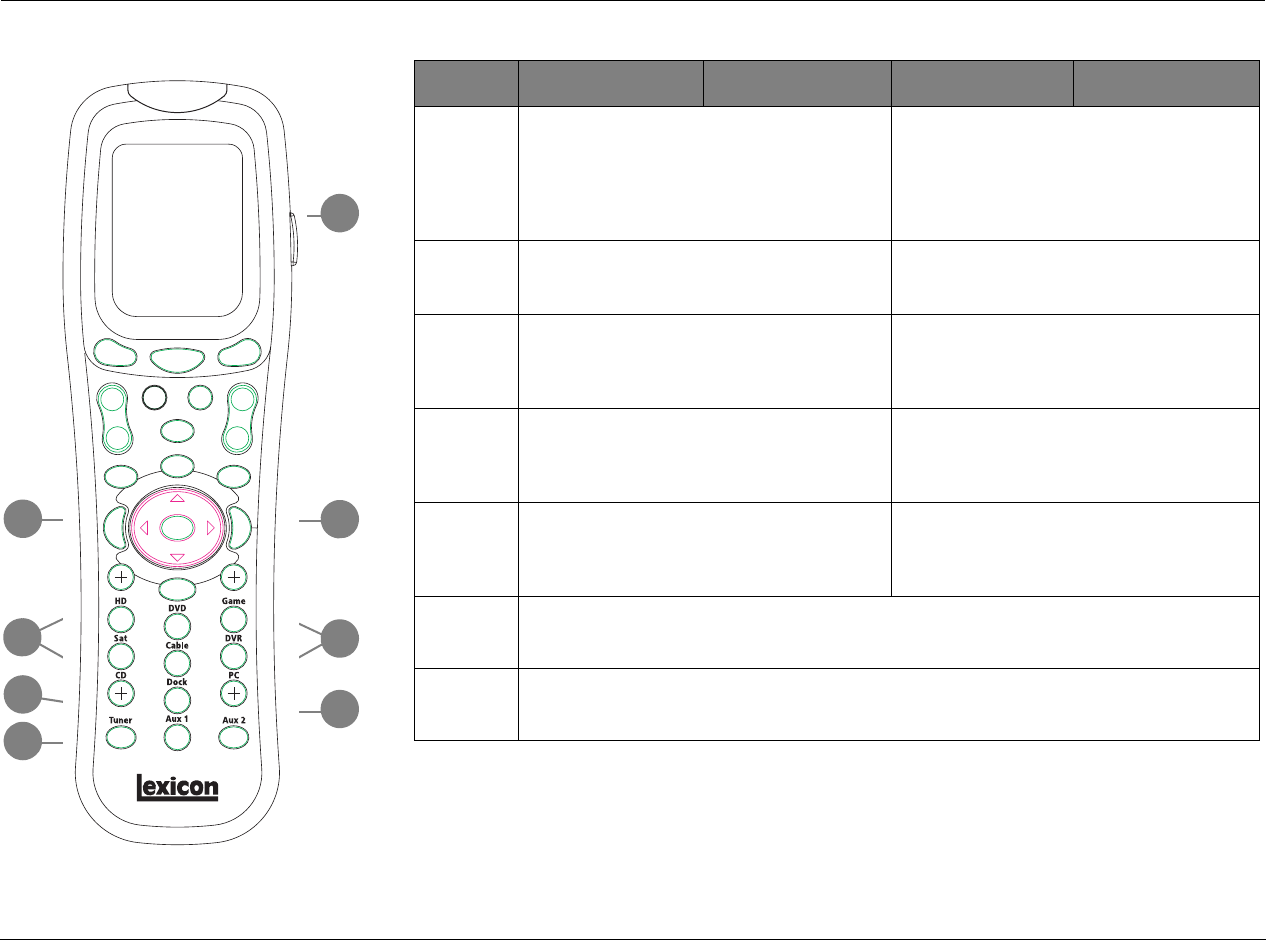
Basic Operation Lexicon
2-26
BUTTON ZONE3 PAGE1 ZONE3 PAGE2 DVD1 PAGE1 DVD1 PAGE2
33 When a menu is open, closes the menu and, in
most cases, opens the previous menu.
Subsequent presses continue to close the current
menu and open the previous menu until
the MAIN MENU is closed. When no menus are
open, this button performs no function.
Navigates to the left in the RT-10 or RT-20 menu
structure.
34 When a menu is open, closes the menu structure.
When no menus are open, shows the
two-line status.
Selects the highlighted RT-10 or RT-20 menu item.
35 Numbers 0 to 9 are used to enter the
frequency of radio stations or to save/load
presets when the RV-5’s built-in tuner is the
currently selected input.
Direct RT-10 or RT-20 title, chapter, group or track
number selection.
36 If the RV-5 built-in tuner is the currently selected
input, toggles between AM/FM frequency
bands.
Enters values 10 and above on the RT-10 or RT-20.
Press once for numbers in the teens, twice for
numbers in the twenties, and so on. Then press a
number button (0 to 9) to enter a second digit.
37 If the RV-5’s built-in tuner is the currently
selected input, saves the currently selected tuner
frequency as a preset. Also used to program the
remote. See page C-4 for additional information.
Deletes entries when RT-10 or RT-20 search modes
and certain playback modes are activated.
38 Macro Buttons: M1 is for Macro 1, M2 is for Macro 2 and M3 is for Macro 3. See page C-9
for additional information on how to use and program macros.
39 Activates the remote-control backlight to illuminate the buttons and LCD screen for easier
visibility.
34
33
39
35
37
35
36
38

RV-5 Basic Operation
2-27
UNDERSTANDING THE ZONES
The RV-5 features two zones of operation: the Main Zone and Zone
2. The Main Zone controls audio and video signals in the primary
listening space. Zone 2 controls digital and analog audio and
composite or S-Video signals for a second zone or recording device.
The following are exceptions to independent zone operation:
1. The same Dolby Digital or DTS(-ES) input source can be simul-
taneously selected for the Main Zone and Zone 2. However,
different Dolby Digital or DTS(-ES) input sources cannot be
present in the Main Zone and Zone 2.
2. Zone 2 can provide a 2-channel downmix of Main Zone multi-
channel audio when all of the following conditions are met:
• The same input must be selected in the Main Zone and
Zone 2.
• A Dolby Digital, DTS(-ES) or 5.1a input source must be
present in the Main Zone.
• The INPUT SETUP menu ZONE2 IN parameter must be set to
DMIX. See “ZONE2 in Parameter Settings” on page 3-22 for
more information.
3. The Zone 2 audio output connectors will receive Front L/R when
a 5.1a source is present in the Main Zone and the ZONE2 IN
parameter is set to ANLG.
4. When 5.1a BYPASS or 2-CH BYPASS is selected, a downmix to
Zone 2 is not available.
TWO-LINE STATUS
The two-line status opens in the on-screen and front-panel displays
whenever the RV-5 detects a change in input source or listening mode.
The Main Zone two-line status appears when the RV-5 detects a Main
Zone change, and the Zone 2 (or Zone 3) two-line status appears
when a Zone 2 (or Zone 3) status change is detected.
The ON-SCREEN DISPLAY menu STATUS parameter is used to
control the length of time the two-line status appears in the on-
screen display. The ON-SCREEN DISPLAY menu POSITION
parameter is used to control the vertical alignment of the two-line
status in the display device screen.
Note:
When the display device is connected to a component video output
connector and the MAIN ADV menu COMPONENT OSD parameter is set
to OFF, the on-screen display does not appear on the associated display.
MAIN ZONE TWO-LINE STATUS
Opens in the on-screen and front-panel
displays whenever the RV-5 detects a Main
Zone status change. The Main Zone two-line
status indicates the current input, input source, listening mode and
volume level selected in the Main Zone.
ZONE 2 TWO-LINE STATUS
Opens in the on-screen and front-panel displays
whenever the RV-5 detects a Zone 2 status
change. The Zone 2 two-line status indicates the
current input, input source and volume level selected in Zone 2.
DVD1 D VOL
FILM -34dB
DVD1 ANLG VOL
ZONE 2 -34dB

Basic Operation Lexicon
2-28
TUNER STATUS
The Tuner status indicates the current frequency,
band, listening mode and volume level. The
Tuner status takes the place of the two-line status
display for inputs using the built-in tuner.
STATUS MENUS
Pressing the remote control STAT2 button opens the STATUS menu
for the current input source of the Main Zone, which contains
parameters that provide information about the current input source
and listening mode. STATUS menus are available for 2-channel,
Dolby Digital, DTS(-ES) and 5.1 analog input sources. Unlike most
other menus, STATUS menus cannot be opened through the
selection of menu options. Rather, the remote control STAT2 button
must be pressed.
To open and navigate the STATUS menu for the current input
source:
1. Under Zone 2 page 2, press “STAT2.” The first page of the
STATUS menu for the current input source appears in the on-
screen and front-panel displays.
If the STATUS menu includes a second page, the PG1 indicator
appears in the top-right corner of the menu. Press the STAT2
button to open the second page. If the STATUS menu does not
include a second page, pressing the STAT2 button closes the
menu. If this occurs, begin again with step 1.
2. When the desired STATUS menu page has been opened, press
the remote-control Menu and arrows to scroll upward and
downward through the complete list of available parameters.
Note:
STATUS menu parameters provide information about the current
input source and listening mode. These parameters cannot be
adjusted.
3. Press the STAT2 button or the Menu arrow to close the
STATUS menu. If the second page of the STATUS menu opens,
press the STAT2 button or the Menu arrow again to close the
STATUS menu.
STATUS menu descriptions begin on the next page. The table
beneath each description lists the default and possible settings
for each parameter. STATUS menu parameter descriptions
begin on page 2-33. STATUS menu level meters are described
on page 2-34.
DVD1 90.9 FM
L7 MUSIC -34dB
RV-5 Basic Operation
2-29
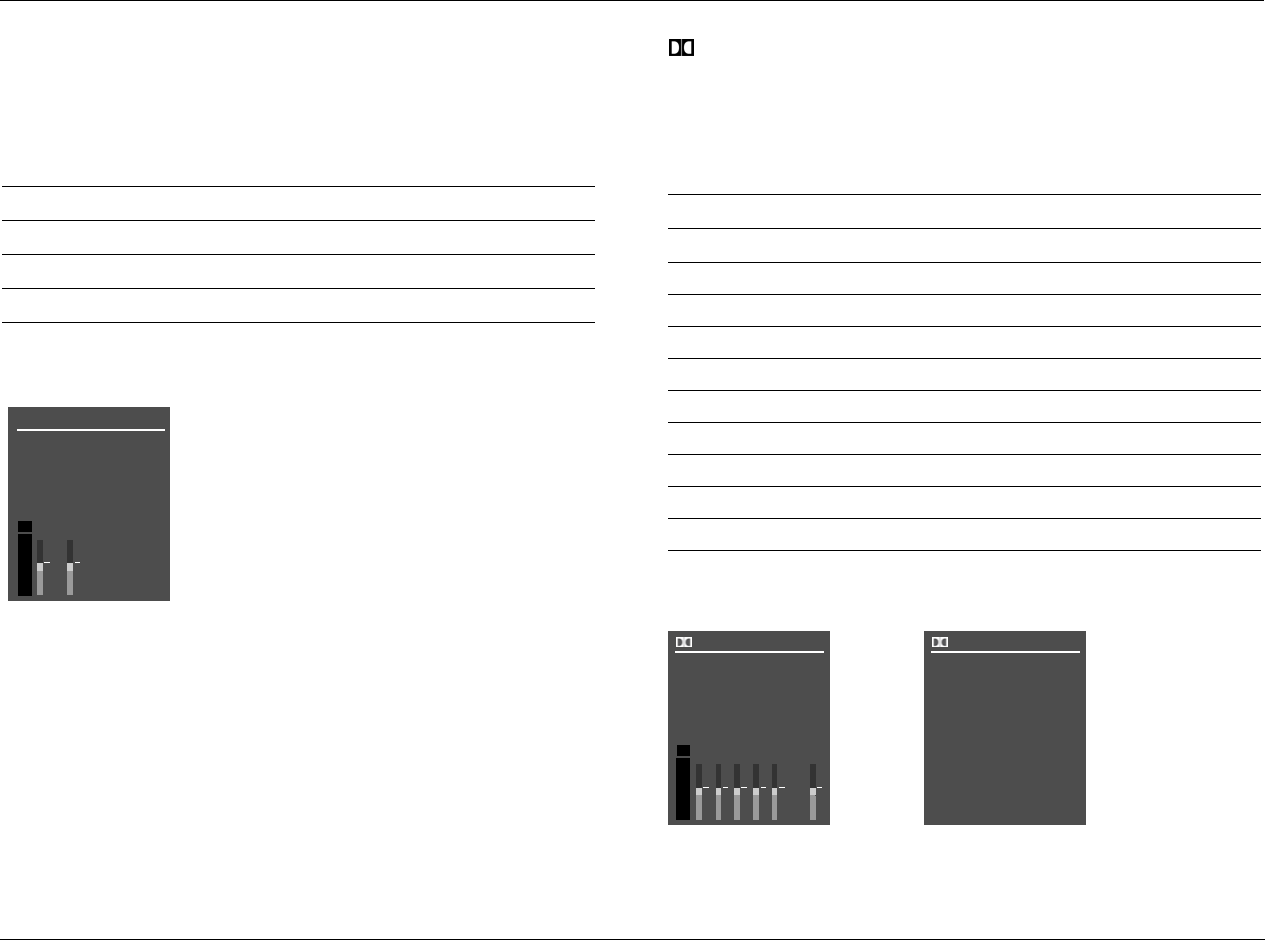
2CH STATUS
Provides information about 2-channel input sources. Features L and
R level meters.
See “STATUS Menu Parameter Descriptions” on page 2-33 for detailed information.
D STATUS
Provides information about Dolby Digital input sources. Features
L, C, R, SL, SR and LFE level meters.
See “STATUS Menu Parameter Descriptions” on page 2-33 for detailed information.
Parameter Possible Settings
INPUT The current input
MODE The current listening mode
INPUT TYPE ANLG, PCM
SAMPLE RATE 44.1kHz, 48kHz, 88.2kHz, 96kHz
2CH STATUS
INPUT
MODE
INPUT TYPE
SAMPLE RATE
dB
0
-6
-15
-30
-45
RL
Parameter Possible Settings
INPUT The current input
MODE The current listening mode
CHANNELS 3/2.1, 3/2, 3/1, 2/2, 2/1, 2/0, 1/0
BIT RATE 32 to 640kbps
EX ENCODED MATRIX, NONE
SAMPLE RATE 48kHz
2.0 ENCODING MATRIX, NONE
DIALOG OFFSET –27 to +4dB
MIX ROOM SMALL, LARGE
CENTER MIX LVL –3.0dB, –4.5dB, –6.0dB
SURR MIX LVL +0.0dB, –3.0dB, –6.0dB
D STATUS
INPUT
MODE
CHANNELS
BIT RATE
RL
EX ENCODED
PG1
CSL
SR LFE
dB
0
-6
-15
-30
-45
D STATUS
SAMPLE RATE
PG2
2.0 ENCODING
DIALOG OFFSET
MIX ROOM
CENTER MIX LVL
SURR MIX LVL
Basic Operation Lexicon
2-30
STATUS
Provides information about DTS(-ES) input sources. Includes L, C, R,
SL, SR, SB and LFE level meters. The SB level meter appears when a
6.1-channel input source is present, or when a 5.1-channel input
source is present and the ES DECODING parameter is set to ON.
See “STATUS Menu Parameter Descriptions” on page 2-33 for detailed information.
5.1a BYPASS STATUS
Provides information about 5.1-channel analog input sources when
the MAIN ADV menu ANALOG BYPASS parameter is set to ON.
See “STATUS Menu Parameter Descriptions” on page 2-33 for detailed information.
Parameter Possible Settings
INPUT The current input
MODE The current listening mode
CHANNELS 3/3.1, 3/2.1
BIT RATE 754.5 to 1509.7 kbps
ES ENCODING DISCRETE, MATRIX, OFF
WORD LENGTH 16 bits, 20 bits, 24 bits
SAMPLE RATE 44.1kHz, 48kHz, 88.2kHz, 96kHz
STATUS
WORD LENGTH
SAMPLE RATE
PG1
STATUS
INPUT
MODE
CHANNELS
BIT RATE
RL
ENCODING
PG1
CSLSRLFE
STATUS
WORD LENGTH
SAMPLE RATE
PG2
dB
0
-6
-15
-30
-45
SB
Parameter Possible Settings
INPUT The current input
MODE 5.1a BYPASS
INPUT TYPE BYPASS
5.1a BYPASS STATUS
INPUT
MODE 5.1a BYPASS
INPUT TYPE BYPASS

RV-5 Basic Operation
2-31
2CH BYPASS STATUS
Provides information about 2-channel analog input sources when
the MAIN ADV menu 2-CH ANLG BYP parameter is set to ON.
See “STATUS Menu Parameter Descriptions” on page 2-33 for detailed information.
DIGITAL STATUS
Provides information about digital input sources for which a sample
rate is detected, but no audio is present in the input signal.
See “STATUS Menu Parameter Descriptions” on page 2-33 for detailed information.
Parameter Possible Settings
INPUT The current input
MODE 2CH BYPASS
INPUT TYPE BYPASS
2CH BYPASS STATUS
INPUT
MODE 2CH BYPASS
INPUT TYPE BYPASS
Parameter Possible Settings
INPUT The current input
MODE The current listening mode
INPUT TYPE ---
SAMPLE RATE 44.1kHz, 48kHz, 88.2kHz, 96kHz
DIGITAL STATUS
INPUT
MODE
INPUT TYPE
SAMPLE RATE

Basic Operation Lexicon
2-32
5.1 ANALOG STATUS
Provides information about 5.1-channel analog input sources.
See “STATUS Menu Parameter Descriptions” on page 2-33 for detailed information.
LIVE! STATUS
Provides information about LIVE! input sources. Features L and R
level meters.
See “STATUS Menu Parameter Descriptions” on page 2-33 for detailed information.
Parameter Possible Settings
INPUT The current input
MODE The current listening mode
INPUT TYPE ANLG
SAMPLE RATE 96kHz
5.1 ANALOG STATUS
INPUT
MODE
INPUT TYPE
SAMPLE RATE
ANLG
96kHz
Parameter Possible Settings
INPUT The current input
MODE The current listening mode
INPUT TYPE MIC
SAMPLE RATE 48kHz
2CH STATUS
INPUT
MODE
INPUT TYPE
SAMPLE RATE
DVD1
LIVE! MED
MIC
48kHz
dB
0
-6
-15
-30
-45
RL

RV-5 Basic Operation
2-33
STATUS MENU PARAMETER DESCRIPTIONS
2.0 ENCODING MATRIX, NONE
Indicates whether or not a matrix-encoded source is detected.
When the parameter setting is MATRIX, a matrix-encoded source is
detected. When the parameter setting is NONE, a matrix-encoded
source is not detected. The RV-5 cannot automatically detect matrix
encoding in non-flagged input sources.
BIT RATE 32 to 640 kbps or 754 to 1509.7kbps
Indicates the rate at which the input signal is encoded. A higher bit
rate indicates that less compression was used during the encoding
process. Possible settings for Dolby Digital sources range from 32 to
640 kbps. Possible settings for DTS(-ES) sources range from 754 to
1509.7 kbps.
CENTER MIX LVL –3.0dB, –4.5dB, –6.0dB
Indicates the relative level of the center channel that was used
during the mixing process.
CHANNELS 3/3.1, 3/2.1, 3/2, 3/1, 2/2, 2/1, 2/0, 1/0
Indicates the number of channels present in the input source. The
first digit indicates the number of front channels present. The digit
after the slash indicates the number of surround channels present.
The digit after the decimal point indicates the presence of LFE (low-
frequency effects) information. For instance, if the parameter setting
is 3/2.1, an input source with three front channels, two surround
channels and LFE information is present. LFE information is sent to
the Main Zone audio output connector labeled Sub.
Possible settings for Dolby Digital input sources include 3/2.1, 3/2,
3/1, 2/2, 2/1, 2/0 and 1/0. Possible settings for DTS(-ES) input
sources include 3/3.1 and 3/2.1.
DIALOG OFFSET –27 to +4dB
Indicates the dialog normalization value applied to the input signal.
Dolby Digital input sources reproduce dialog at 27 decibels below full-
scale (–27dBFS). When the dialog normalization value of the incoming
signal is higher or lower, the DIALOG OFFSET parameter indicates the
amount of adjustment the RV-5 makes to normalize dialog to –27dBFS.
ES ENCODING DISCRETE, MATRIX, OFF
Indicates whether or not a DTS-ES-encoded source is detected.
When the parameter setting is DISCRETE, a discrete 6.1-channel
DTS-ES source is detected. When the parameter setting is MATRIX,
a 5.1-channel DTS-ES source with a surround-encoded back
channel is detected. When the parameter setting is NONE, a
standard DTS source with no DTS-ES encoding is detected.
EX ENCODING MATRIX, NONE
Indicates whether or not a Dolby Digital Surround EX-encoded source
is detected. When the parameter setting is MATRIX, a 5.1-channel
Dolby Digital source recorded with Dolby Digital Surround EX is
detected. When the parameter setting is NONE, a standard 5.1-
channel Dolby Digital source recorded without Dolby Digital Surround
EX encoding is detected. The RV-5 cannot automatically detect Dolby
Digital Surround EX encoding in non-flagged input sources.

Basic Operation Lexicon
2-34
INPUT
Indicates the selected input (e.g., DVD1).
INPUT TYPE ANLG, BYP, PCM, MIC, ---
Indicates the input source that is present. When the parameter
setting is ANLG, a 2-channel analog audio source is present and the
MAIN ADV menu 2-CH ANLG BYP parameter is set to OFF. When
the parameter setting is BYP (Bypass), a 2-channel analog audio
source is present and the 2-CH ANLG BYP parameter is set to ON.
When the parameter setting is PCM, a 2-channel digital audio
source is present. When the parameter is set to MIC, a microphone
source is present. When the parameter setting is ---, an unknown
digital audio source is present.
MIX ROOM SMALL, LARGE
Indicates the size of the mixing room that was used during the
mixing process. When the parameter setting is LARGE, setting the
RE-EQUALIZATION parameter to ON for THX listening modes is
recommended.
MODE
Indicates the activated listening mode (e.g., L7 FILM).
SAMPLE RATE 44.1kHz, 48kHz, 88.2kHz, 96kHz
Indicates the sample rate of the input source that is present.
SURR MIX LVL +0.0dB, –3.0dB, –6.0dB
Indicates the relative surround channel level that was used during
the mixing process.
WORD LENGTH 16 bits, 20 bits, 24 bits
Indicates the word length of the audio data present in the input signal.
STATUS MENU LEVEL METERS
Most STATUS menus contain level meters that indicate fluctuating
input levels in the front left (L), center (C), front right (R), surround left
(SL), surround right (SR), surround back (SB) and subwoofer (SUB)
channels. These level meters indicate input levels for both analog and
digital input sources. For instance, the level meters indicate digital
audio input levels when a digital audio source is present.
Different combinations of level meters appear on each STATUS menu,
depending on the source that is present. The SB level meter appears
when a 6.1-channel source is present, or when a 5.1-channel source
is present and the ES DECODING parameter is set to ON.
Level meters appear in combinations of green, yellow and red when
the on-screen display is configured for a blue-screen background.
Green indicates low levels, yellow indicates normal levels, and red
indicates high levels and the onset of overload. Level meters appear
in white when the on-screen display is not configured for a blue-
screen background.

3
Setup
Setup ..........................................................................................3-2
Input Setup.................................................................................3-4
Changing Input Names............................................................................. 3-5
Assigning Audio and Video Input Connectors ........................................... 3-7
Selecting Preferred Listening Modes........................................................ 3-12
Configuring Advanced Input Settings...................................................... 3-17
INPUT SELECT Parameter Settings........................................................... 3-19
ZONE2 in Parameter Settings.................................................................. 3-22
Speaker Setup ...........................................................................3-25
Setting Crossover Points.......................................................................... 3-25
Speaker Setup Parameters....................................................................... 3-29
Automatic Calibration ............................................................................. 3-36
Manual Calibration ................................................................................. 3-53
I/O Config.................................................................................3-60
Display Setup ............................................................................3-63
On-Screen Display Setup ........................................................................ 3-64
Front-panel Display Setup ....................................................................... 3-66
Volume Control Setup...............................................................3-68
Trigger Setup ............................................................................3-70
Tuner Setup ..............................................................................3-72
Tuner Region Band Limit And Increments ............................................... 3-73
Lock Options.............................................................................3-79
LIVE! CALIBRATION ...................................................................3-80
Setup Lexicon
3-2
SETUP
Selecting SETUP from the MAIN MENU opens the SETUP menu.
DISPLAY SETUP
Opens the DISPLAY SETUP menu, which is used to customize the
on-screen and front-panel displays, identify display connection types,
and set the aspect ratio. See “DISPLAY SETUP” on page 3-5 for more
information.
INPUT SETUP
Opens the INPUT SETUP menu, which is used to change input
names, assign audio and video input connectors, select preferred
listening modes and configure Main Zone and Zone 2 input settings.
See “INPUT SETUP” on page 3-5 for more information.
SURROUND CONFIG
Opens the DISPLAY SETUP menu, which is used to customize the on-
screen and front-panel displays, restore audio/video synchronization,
and create and activate a custom unit name. See “DISPLAY SETUP”
on page 3-63 for more information.
DOLBY CONFIG
Opens the VOLUME CONTROL SETUP menu, which is used to configure
Main Zone, Mute, Zone 2, Zone 3 and Headphone volume levels. See
“VOLUME CONTROL SETUP” on page 3-68 for more information.
SPEAKER/EQ SETUP
Opens the SPEAKER SETUP menu, which is used to configure the
Main Zone audio output connectors for the desired speaker setup,
set speaker distances and calibrate output levels. See “SPEAKER
SETUP” on page 3-23 for more information.
POWER ON SETTINGS
Opens the TUNER SETUP menu, which is used to configure the AM/
FM tuner. See “TUNER SETUP” on page 3-72 for more information.
MAIN MENU
AUDIO CONTROLS
VIDEO CONTROLS
DISPLAY SETUP
SETUP
SETUP
SPEAKER/EQ SETUP
INPUT SETUP
SURROUND CONFIG
DOLBY CONFIG
MUTE LEVELS
POWER ON SETTINGS
SETUP DISPLAY SETUP
INPUT SETUPSETUP
SURROUND CONFIGSETUP
DOLBY CONFIGSETUP
SPEAKER/EQ SETUPSETUP
POWER ON SETTINGS
SETUP
RV-5 Setup
3-3
DISPLAY SETUP
Selecting the SETUP menu DISPLAY SETUP option opens the DISPLAY SETUP menu, which is used to customize the on-screen and front-panel
displays, restore audio/video synchronization, and activate and create a custom unit name.
DISPLAY TYPE CRT, DLP, F-PRJ, LCD, PLASMA, R-PRJ
Opens the DISPLAY TYPE menu, which is used to assign the appropri-
ate video display type.
ASPECT RATIO 4:3, 16:9
Opens the ASPECT RATIO menu, which is used to assign the appro-
priate aspect ratio. The 4:3 aspect ratio is almost square and most
commonly used for television. The 16:9 aspect ratio, also referred to
as Widescreen, is almost twice as wide as it is high.
CONNECTION ANALOG, HDMI/DVI
Opens the CONNECTION menu, which identifies the type of video
signal that is input to the display.
HDMI AUDIO OUT YES, NO
Opens the ASPECT RATIO menu, which is used to assign the appro-
priate aspect ratio. The 4:3 aspect ratio is almost square and most
commonly used for television. The 16:9 aspect ratio, also referred to
as Widescreen, is almost twice as wide as it is high.
SETUP DISPLAY SETUP
MAIN MENU
AUDIO CONTROLS
VIDEO CONTROLS
SETUP 7.1 SETUP:
SURROUND CONFIG
DOLBY CONFIG
SPEAK/EQ SETUP
POWER ON SETTINGS
5.1+DSP
SETUP
INPUT SETUP
DISPLAY SETUP
DISPLAY SETUP
DISPLAY TYPE:
ASPECT RATIO:
CONNECTION:
HDMI AUDIO OUT:
ON-SCREEN DISPLAY
FRONT PAN DISPLAY
CRT
4:3
HDMI/DVI
YES
ON-SCREEN DISPLAY SETUP
2-LINE OSD:
FULL OSD:
OFF
50s
FRONT PAN DISPLAY SETUP
BRIGHTNESS:
TIME OUT:
FULL
OFF
DISPLAY SETUPSETUP DISPLAY TYPE
DISPLAY SETUPSETUP ASPECT RATIO
DISPLAY SETUPSETUP CONNECTION
DISPLAY SETUPSETUP HDMI AUDIO OUT
Setup Lexicon
3-4
2-LINE OSD OFF, 3 TO 6 SECONDS
Opens the 2-LINE OSD menu, which is used to set the time that the
2-Line status display is visible. The OFF setting ensures that the
display is always visible. The 2-Line OSD can be set to turn off in 3 to
6 seconds, selectable in 1-second increments.
FULL OSD 30, 40, 50, 60 SECONDS
Opens the FULL OSD menu, which is used to set the time that the
on-screen status display is visible. The OFF setting ensures that the
display is always visible. The FULL OSD can be set to turn off in 30 to
60 seconds, selectable in 10-second increments.
BRIGHTNESS FULL, HALF, OFF
Opens the BRIGHTNESS menu, which is allows the user to set the
brightness level of the RV-5 front display.
TIME OUT OFF, 1 TO 10 SECONDS
Opens the TIME OUT menu, which allows the user to set the time out
period or to disable the time out feature. The time delay parameters
are 1 to 10 seconds, selectable in 1-second increments.
DISPLAY SETUPSETUP ON-SCREEN DISPLAY 2-LINE OSD
DISPLAY SETUPSETUP ON-SCREEN DISPLAY FULL OSD
DISPLAY SETUPSETUP FRONT PAN DISPLAY BRIGHTNESS
DISPLAY SETUPSETUP FRONT PAN DISPLAY TIME OUT
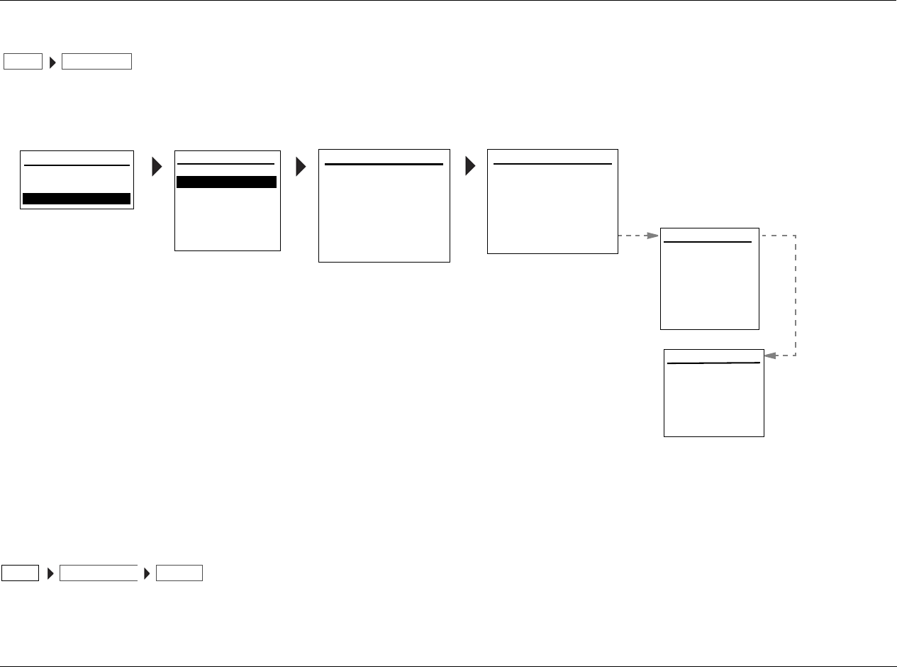
RV-5 Setup
3-5
INPUT SETUP
Selecting the SETUP menu INPUT SETUP option opens the INPUT SETUP menu, a two-screen menu which sets up the input type and name, the
digital and analog inputs for both audio and video, the listening mode, speaker configuration, and other advanced input settings.
All INPUT SETUP menus are shown in the Appendix on page A-6. The parameters on the left side of the INPUT SETUP menus are identical,
regardless of which input is selected. The parameter settings on the right side are adjustable. Default parameter settings differ from input to input.
The INPUT SETUP menus shown in the Appendix indicate factory-default parameter settings for each input.
INPUT HD, DVD, GAME, SAT, CABLE, DVR, CD,
DOCK, PC, TUNER, AUX 1, AUX 2
Opens the INPUT menu, which is used to assign the appropriate
input type.
INPUT SETUPSETUP
The DVD1 INPUT SETUP menu is shown here as an example, and will continue to be shown as an example throughout this section.
Whenever it appears, any other INPUT SETUP menu can be substituted. Likewise, whenever the DVD1 input appears as a step in a
menu path, any other input can be substituted.
INPUTS
SPEAKERS
I/O CONFIG
DISPLAYS
VOLUME CONTROLS
TRIGGER
TUNER SETUP
FLESHTONE NR:
COMPNT ENHANCE:
BRIGHTNESS:
CONTRAST:
COLOR:
TEST PAT:
100
ADVANCED VIDEO 2
MAIN MENU
AUDIO CONTROLS
VIDEO CONTROLS
SETUP
DISPLAY SETUP
8-CH INPUT:
SURROUND CONFIG
DOLBY SURR SETUP
SPEAKER/EQ SETUP
POWER ON SETTINGS
5.1+A/D
SETUP
INPUT SETUP
INPUT SETUP: INPUT SETUP 1
INPUT:
NAME: ________
DIG AUDIO:
ANLG AUDIO:
DIG/ANLG AUTO:
A/D SAMPLE RATE:
DVD 1
ON
HDMI 2
NONE
MODE FAMILY:
MODE:
48kHz
STEREO
2-CHANNEL
INPUT SETUP: INPUT SETUP 2
DEFAULT SUR:
VIDEO IN:
V-PROCESS:
ZONE 2OUT:
ADVANCED VIDEO
ON
BYPASS
- - -
A/V SYNC DELAY:
TRIGGER 2:
HDMI 2
0 ms
ANALOG
USE LASTUSE LAST
ON
100
100
OFF
ON
INPUT TYPE:
SHARPNESS:
NOISE REDUCTION:
X-COLOR SUPRESS:
DCDi INTERPOL:
FILM DETECTION:
FILM EDIT DETECT:
ON
ADVANCED VIDEO 1
32
ON
ON
ON
ON
VCR
INPUT SETUPSETUP INPUT
Setup Lexicon
3-6
CHANGING INPUT NAMES
Selecting the INPUT SETUP menu NAME parameter opens the INPUT NAME menu, which is used to customize or restore the factory-default name
of the selected input. Factory-default input names correspond to front-panel and remote-control input selection button labels.
EDIT INPUT NAME
Opens the EDIT INPUT NAME drop-down menu, which is used to
customize the name of the selected input. Custom input names can
include up to eight characters.
To customize the name of the selected input:
1. Follow the EDIT INPUT NAME menu path to open the EDIT INPUT
NAME drop-down menu.
2. When the EDIT INPUT NAME menu opens, the current input
name appears on the second line. Using the remote-control
and arrow buttons, change the character above the cursor (^).
3. When the desired character has been changed, press the arrow
button to advance to the next character space. The cursor will
automatically wrap to the first character space when the last
character space is passed.
4. Repeat steps 2 and 3 to enter all characters in the new name.
5. When the desired input name has been entered, press the arrow
button to close the menu and return to the INPUT NAME menu.
The custom input name appears in the on-screen and front-panel
displays. Both the custom and factory-default input names appear in
the INPUT SETUP menu. The custom input name appears against the
left margin of the on-screen display, and the factory-default input
name appears in parentheses against the right margin.
DVD1 INPUT NAME
RESTORE DEFAULT NAME
EDIT INPUT NAME
DVD
BUTTONS TO EDIT
UP TO 8 CHARACTERS
BUTTON TO ADVANCE
>
EDIT INPUT NAME
INPUTS
SPEAKERS
I/O CONFIG
DISPLAYS
VOLUME CONTROLS
TRIGGER
TUNER SETUP
MAIN MENU
AUDIO CONTROLS
VIDEO CONTROLS
SETUP
DISPLAY SETUP
8-CH INPUT:
SURROUND CONFIG
DOLBY SURR SETUP
SPEAKER/EQ SETUP
POWER ON SETTINGS
5.1+A/D
SETUP
INPUT SETUP
INPUT SETUP: INPUT SETUP 1
INPUT:
DIG AUDIO:
ANLG AUDIO:
DIG/ANLG AUTO:
A/D SAMPLE RATE:
DVD 1
ON
HDMI 2
NONE
MODE FAMILY:
MODE:
48kHz
STEREO
2-CHANNEL
NAME: ________
INPUT SETUPSETUP NAME EDIT INPUT NAME
RV-5 Setup
3-7
ASSIGNING AUDIO and VIDEO INPUT CONNECTORS
The RV-5 has eight configurable inputs, each of which can be assigned to its ten digital audio, eight analog audio, the built-in tuner, the phono
input, two HDMI video, four composite video, four S-Video or three component video input connectors.
The table below indicates the INPUT SETUP menu parameters that
can be used to assign audio and video input connectors.
Note:
The digital audio input connectors are compatible with PCM (44.1, 48,
88.2 and 96kHz), Dolby Digital and DTS (-ES) sources. The digital audio
input connectors are also compatible with MPEG or MP3 sources through
the DOCK input.
DIG AUDIO COAXIAL-1 to 4, HDMI-1, HDMI-2,
OPTICAL-1 to 4, NONE
Opens the DIG AUDIO menu, which is used to assign a digital audio
input connector for the selected input. The RV-5 has ten configurable
inputs, each of which can be assigned to any of its ten digital audio
input connectors.
Please note the following:
• When no digital audio input connector is assigned, the RV-5 will
automatically set the MAIN ADV menu INPUT SELECT
parameter to ANALOG (see page 3-15).
• A digital audio input connector must be assigned when no
analog audio input connector is assigned. Refer to the next page
for information about assigning an analog audio input
connector.
DVD DIG AUDIO
COAXIAL-2
COAXIAL-3
COAXIAL-4
OPTICAL-1
OPTICAL-2
OPTICAL-3
OPTICAL-4
INPUTS
SPEAKERS
I/O CONFIG
DISPLAYS
VOLUME CONTROLS
TRIGGER
TUNER SETUP
MAIN MENU
AUDIO CONTROLS
VIDEO CONTROLS
SETUP
DISPLAY SETUP
8-CH INPUT:
SURROUND CONFIG
DOLBY SURR SETUP
SPEAKER/EQ SETUP
POWER ON SETTINGS
5.1+A/D
SETUP
INPUT SETUP
HDMI 2
NONE
HDMI 1
HDMI 2
COAXIAL-1
INPUT SETUP: INPUT SETUP 1
INPUT:
DIG AUDIO:
ANLG AUDIO:
DIG/ANLG AUTO:
A/D SAMPLE RATE:
DVD 1
ON
HDMI 2
NONE
MODE FAMILY:
MODE:
48kHz
STEREO
2-CHANNEL
NAME: ________
Parameter Possible Settings
DIG AUDIO COAX-1 to 4, HDMI-1, HDMI-2, OPTICAL-1 to 4,
NONE
ANLG AUDIO ANALOG-1 to 6, 7.1 CHANNEL, TUNER, NONE
VIDEO IN COMPONENT-1 to 3, COMPOSITE-1 to 4,
HDMI-1, HDMI-2, S-VIDEO-1 to 4
INPUTSETUP DIG AUDIO
Setup Lexicon
3-8
ASSIGNING AUDIO and VIDEO INPUT CONNECTORS (continued)
ANALOG IN ANALOG-1 to 6, 7.1 CHANNEL, TUNER, NONE
Opens the ANLG AUDIO menu, which is used to assign an analog
audio input connector for the selected input. The RV-5 has eight
configurable inputs, each of which can be assigned to any of its eight
analog audio input connectors.
The appearance of the ANLG AUDIO menu depends on the configu-
ration of the analog audio input connectors.
• The ANALOG IN menu (A above) appears when the I/O CONFIG
menu 8 STEREO INPUTS option is selected (see page 3-60).
• The ANALOG IN menu (B above) appears when the I/O CONFIG
menu 5 ST. & 5.1 ANLG option is selected (see page 3-61).
• The ANALOG IN menu (C above) appears when the I/O
CONFIG menu 2 ST. & (2) 5.1 ANLG option is selected (see
page 3-61).
Please note the following:
• When no analog audio input connector is assigned, the RV-5
automatically sets the MAIN ADV menu INPUT SELECT
parameter to DIGITAL (see page 3-15).
• An analog audio input connector must be assigned when no
digital audio input connector is assigned. Refer to the previous
page for information about assigning a digital audio input
connector.
• The TUNER input corresponds with the internal AM/FM radio
tuner.
DVD1 ANLG AUDIO
ANALOG-2
ANALOG-3
ANALOG-4
ANALOG-5
ANALOG-6
7.1 CHANNEL
TUNER
INPUTS
SPEAKERS
I/O CONFIG
DISPLAYS
VOLUME CONTROLS
TRIGGER
TUNER SETUP
MAIN MENU
AUDIO CONTROLS
VIDEO CONTROLS
SETUP
DISPLAY SETUP
8-CH INPUT:
SURROUND CONFIG
DOLBY SURR SETUP
SPEAKER/EQ SETUP
POWER ON SETTINGS
5.1+A/D
SETUP
INPUT SETUP
INPUT SETUP: INPUT SETUP 1
INPUT:
DIG/ANLG AUTO:
A/D SAMPLE RATE:
DVD 1
ON
MODE FAMILY:
MODE:
48kHz
STEREO
2-CHANNEL
NAME: ________
NONE
ANALOG-1
DIG AUDIO: HDMI 2
ANLG AUDIO: NONE
INPUTSETUP ANLG AUDIO
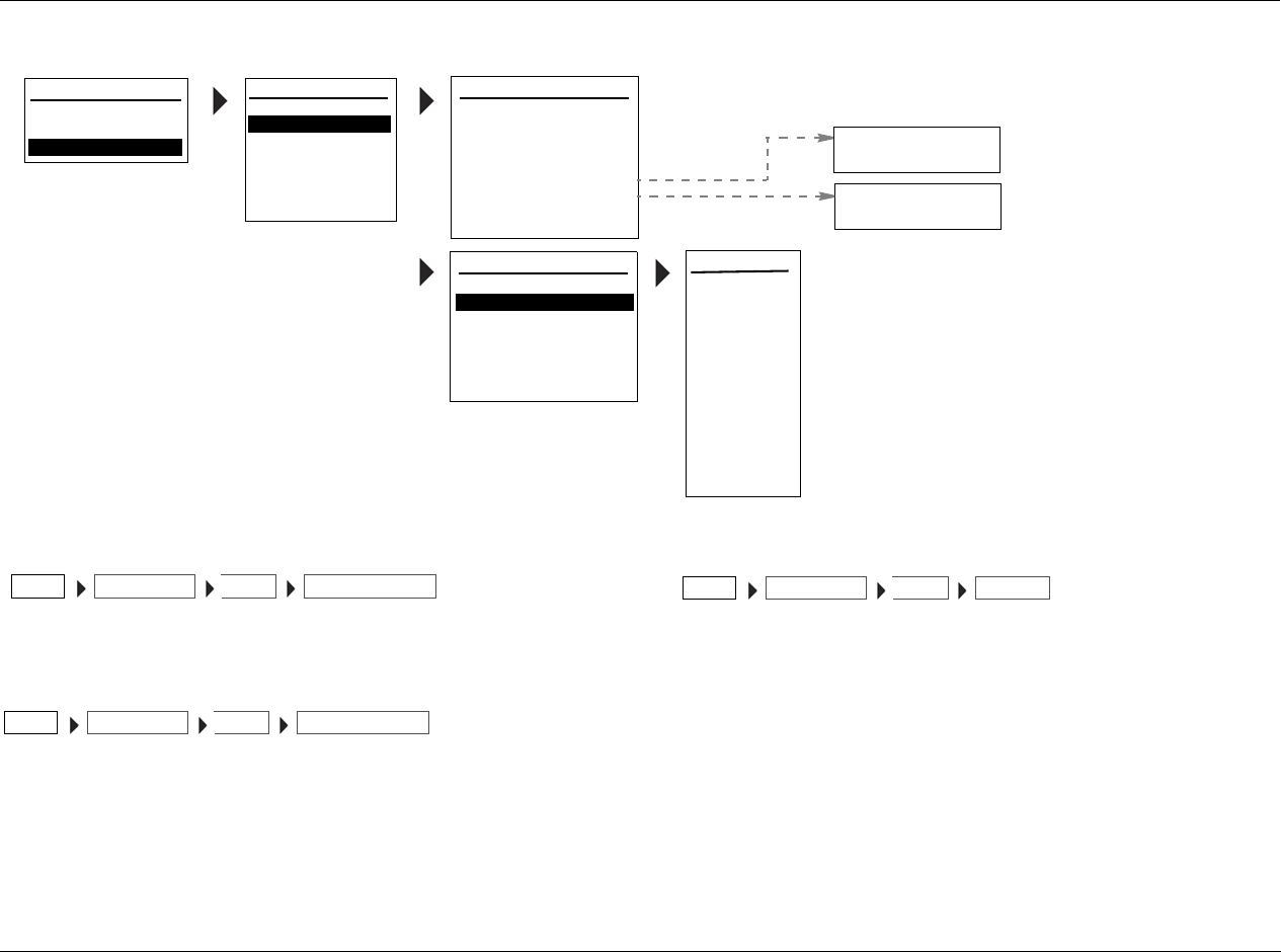
RV-5 Setup
3-9
DIG/ANLG AUTO ON, OFF
Opens the DIG/ANLG AUTO menu, which ...
A/D SAMPLE RATE 48kHz, 96kHz
Opens the A/D SAMPLE RATE menu, which...
VIDEO IN HDMI-1, HDMI-2, COMPONENT-1 to 3,
S-VIDEO-1 to 4, COMPOSITE-1 to 4
Opens the VIDEO IN menu, which is used to assign the input
connector for the selected input. The RV-5 has thirteen configurable
video inputs, each of which can be assigned to any of its two HDMI,
four component, four S-Video, or four composite input connectors.
Note:
Composite video output connectors are available when a composite or
S-Video source is present. S-Video output connectors are available when
an S-Video source is present. The HDMI output connectors are available
when there is an HDMI source present.
DVD1 VIDEO IN
COMPONENT 2
COMPONENT 3
S-VIDEO 1
S-VIDEO 2
S-VIDEO 3
S-VIDEO 4
COMPOSITE 1
INPUTS
SPEAKERS
I/O CONFIG
DISPLAYS
VOLUME CONTROLS
TRIGGER
TUNER SETUP
MAIN MENU
AUDIO CONTROLS
VIDEO CONTROLS
SETUP
DISPLAY SETUP
8-CH INPUT:
SURROUND CONFIG
DOLBY SURR SETUP
SPEAKER/EQ SETUP
POWER ON SETTINGS
5.1+A/D
SETUP
INPUT SETUP
INPUT SETUP: INPUT SETUP 1
INPUT:
DIG AUDIO:
ANLG AUDIO:
DIG/ANLG AUTO:
A/D SAMPLE RATE:
DVD 1
ON
HDMI 2
NONE
MODE FAMILY:
MODE:
48kHz
STEREO
2-CHANNEL
NAME: ________
HDMI 1
COMPONENT 1
ON
OFF
INPUT SETUP: INPUT SETUP 2
DEFAULT SUR:
VIDEO IN:
V-PROCESS:
ZONE 2OUT:
ADVANCED VIDEO
ON
BYPASS
- - -
A/V SYNC DELAY:
TRIGGER 2:
HDMI 2
0 ms
ANALOG
USE LASTUSE LAST
HDMI 2
COMPOSITE 2
COMPOSITE 3
COMPOSITE 4
96kHz
48kHz
INPUT SETUPSETUP DIG/ANLG AUTOINPUT
INPUT SETUPSETUP A/D SAMPLE RATEINPUT
INPUT SETUPSETUP VIDEO ININPUT

Setup Lexicon
3-10
SELECTING PREFERRED LISTENING MODES
Preferred listening modes can be pre-selected so that when a
particular type of input source is played, the pre-selected listening
mode is activated.
The RV-5 allows five preferred listening modes for each Main Zone
input: one listening mode each for 2-channel, Dolby Digital,
DTS(-ES), 5.1a and MIC (LIVE!) sources. The table to the right
indicates the INPUT SETUP menu parameters that can be used to
select preferred listening modes.
Menus showing DVD1 parameters selected as preferred listening modes.
Preferred Listening Mode Selection Parameters
2-CH Selects a preferred listening mode for 2-channel sources
DSelects a preferred listening mode for Dolby Digital sources
Selects a preferred listening mode for DTS(-ES) sources
5.1a Selects a preferred listening mode for 5.1 analog sources
MIC
Selects a preferred listening mode for microphone sources (LIVE!)
DVD1 2-CH MODE
FILM
TV
MUSIC
MUSIC SURR
PLII MOVIE
PLII MUSIC
PRO LOGIC
NIGHTCLUB
CONCERT HALL
CHURCH
CATHEDRAL
PANORAMA
2-CH SURROUND
2-CHANNEL
MONO LOGIC
MONO SURROUND
MONO
HEADPHONE
DVD1 D MODE
FILM
TV
MUSIC
DIGITAL
5.1 2-CHANNEL
5.1
5.1
5.1
5.1 MONO LOGIC
5.1 MONO SURR
5.1 MONO
HEADPHONE 5.1
DVD1 MODE
FILM
MUSIC
2-CHAN
HEADPHONE
DVD1 INPUT SETUP
NAME
DIGITAL IN
ANALOG IN
VIDEO IN
COMPONENT IN
2-CH
D
DVD1
COAX-1
NONE
AUTO
S-VIDEO-1
1
FILM
5.1 FILM
FILM
ANLG IN LVL
MAIN ADVANCED
ZONE2 IN DIGITAL
ZONE2 ADVANCED
5.1a FILM
5.1a
INPUT SETUP
DVD2
TV
SAT
VCR
CD
TUNER
PHONO
DVD1
MAIN MENU
MODE ADJUST
AUDIO CONTROLS
TUNER PRESETS
SETUP
SETUP
INPUTS
SPEAKERS
I/O CONFIG
DISPLAYS
VOLUME CONTROLS
TRIGGER
LOCK OPTIONS
LIVE! CALIBRATION
TUNER SETUP
USE LAST
USE LAST
USE LAST
DVD1 5.1a MODE
FILM
MUSIC
5.1a
5.1a
5.1a STANDARD
5.1a 2-CHANNEL
HEADPHONE 5.1a
USE LAST
POWER MANAGEMENT
RV-5 Setup
3-11
When a preferred listening mode is selected, that listening mode is
automatically activated whenever a new input is selected or an
appropriate input source is present. For example, the following can
occur when a preferred listening mode is activated (also refer to the
corresponding menus on 3-10):
If the DVD1 input is selected and a 2-channel source is played, the
L7 FILM listening mode is activated. If a Dolby Digital source is
played, the 5.1 L7 FILM listening mode is activated. If a DTS(-ES)
source is played, the DTS(-ES) L7 FILM listening mode is activated.
Dynamic Listening Modes
Dynamic listening modes are only available under certain conditions.
For example, many of the dynamic modes are only available when
the RV-5 is configured for seven main output channels and source
material with specific encoding is played. All Dynamic Listening
Modes are available through the remote control or front panel Mode
button. The dynamic listening modes are listed in the table below.
Modes that Do Not Appear in the Input Setup Menu
The RV-5 features the ability to assign preferred listening modes for
each input and incoming audio format. However, not all listening
modes will appear in the Input Setup Menu. Listening modes that do
not appear in the Input Setup menu as preferred listening modes
under any circumstances are listed in the table below.
Dynamic modes
2-Channel Dolby Digital DTS
Dolby PLIIx + THX Dolby Digital or Dolby Digital EX DTS THX or DTS THX UL2Cin or DTS ES THX
Dolby PLIIx MOV THX or THX UL2Cin or THX SurEX DTS or DTS ES MATRIX or DTS ES DISCR
Dolby PLIIx MUS THX MUSIC DTS THX MUSIC
DTS NEO:6 + THX 5.1 PLIIx MOV DTS L7 FILM or DTS ES L7 FILM
DTS NEO:6 CIN 5.1 PLIIx MUS DTS L7 MUSIC or DTS ES L7 MUSIC
DTS NEO:6 MUSIC DTS 2-CHAN or DTS ES 2-CHAN
Modes that do not appear in the Input Setup menu
2-Channel Dolby Digital DTS
Dolby PLIIx + THX THX MUSIC DTS THX MUSIC
Dolby PLIIx MOV 5.1 PLIIx MOV 5.1 MONO LOGIC
Dolby PLIIx MUS 5.1 PLIIx MUS 5.1 MONO SURR
DTS NEO:6 + THX 5.1 MONO
DTS NEO:6 CIN
Setup Lexicon
3-12
SELECTING PREFERRED LISTENING MODES (continued)
The Use Last Parameter
When the RV-5 is set to use a preferred listening mode for a selected
input, selecting another mode from the Mode scroll list replaces the
preferred selection. However, this newly selected mode will be lost
when switching between inputs.
The USE LAST parameter was designed to allow the RV-5 software to
“remember” the last used listening mode for a given input source.
Once selected, that mode will always be active on the corresponding
input until another listening mode is selected as demonstrated in the
following example:
1. Select
Main Menu
SETUP
INPUTS
DVD1
USE LAST
.
2. Press the MENU button.
3. Press the DVD-1 button.
4. Play a DTS input source.
5. Press the MODE + button until you reach DTS(-ES) 2-CHAN.
6. Press the TV button
The RV-5 switches to the TV input and the on-screen display
identifies the preferred listening mode.
7. Press the DVD-1 button.
The on-screen display should identify that the active listening mode
for the DVD1 input is still DTS(-ES) 2-CHAN. As the DTS(-ES)
2-CHAN mode is a preferred listening mode, it can also be set in
the SETUP menu.
When seven speakers are selected in the SPEAKER SETUP menu, and
the appropriate source material is played, the dynamic listening
mode (or mode that does not appear in the input setup menu) can
always be accessed using the MODE + or MODE - buttons whether
or not a preferred mode is set. When a preferred listening mode is set
and a dynamic listening mode (or mode that does not appear in the
input setup menu) is active, the selected dynamic mode is lost when
switching between inputs.
When USE LAST is selected as the preferred listening mode, and a
dynamic listening mode (or mode that does not appear in the input
setup menu) is active, the selected listening mode is retained when
switching between inputs, even when the RV-5 is set to standby as in
the following example:
1. Select
Main Menu
SETUP
INPUTS
DVD1
2-CH
USE LAST
.
2. Press the MENU button.
3. Press the DVD-1 button.
4. Play a 2-channel input source.
5. Press the MODE + button until you reach PLIIx MOV.
PLIIx MOV is a dynamic listening mode.
6. Press the TV button
The RV-5 switches to the TV input and the on-screen display
identifies the preferred listening mode.
7. Press the DVD-1 button.
DTS NEO:6 MUSIC
Modes that do not appear in the Input Setup menu
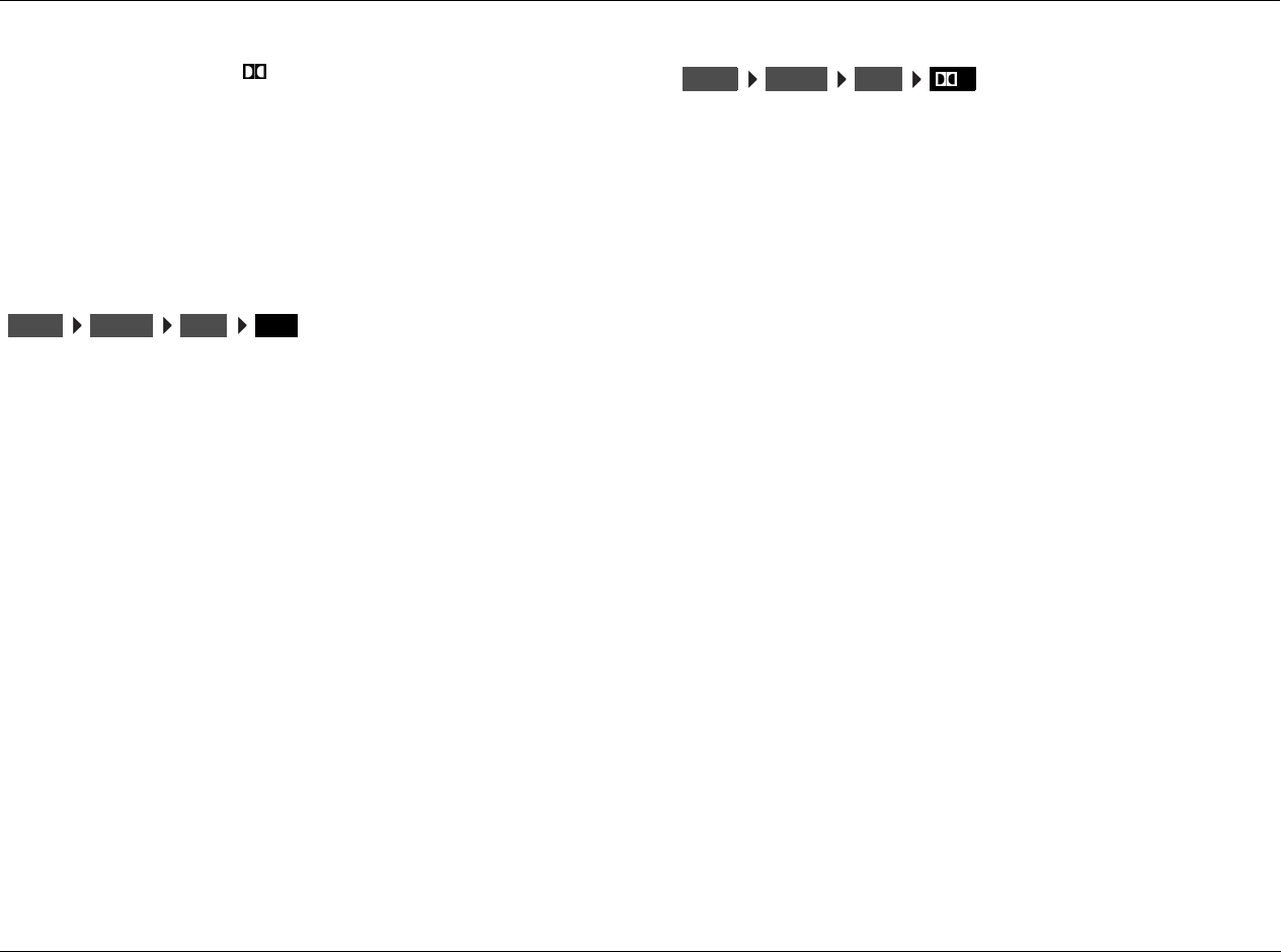
RV-5 Setup
3-13
The on-screen display should identify that the active listening mode
for the DVD1 input is still PLIIx MOV. This is the only method of
setting up a dynamic mode (or mode that does not appear in the
input setup menu) to behave like a preferred listening mode.
Note:
When a dynamic mode (or mode that does not appear in the input setup
menu) is set as in the above example, the setting is retained even when
the RV-5 is set to standby.
2-CH
Opens the 2-CH MODE menu, which is used to select a preferred
listening mode for 2-channel input sources. The RV-5 activates the
selected listening mode whenever a 2-channel source is present.
When the 2-CH parameter is set to USE LAST:
The RV-5 activates the listening mode that was activated the last time
a 2-channel source was present
The remote control 2 CH button toggles between the 2-CHANNEL
listening mode and the previous listening mode, and ignores the USE
LAST setting. Instead, it uses the listening mode (for example, L7
FILM) that was activated before the 2-CHANNEL listening mode.
The RV-5 activates a DTS NEO:6 listening mode if a DTS NEO:6
listening mode was activated the last time a 2-channel source was
present, and a 44.1kHz or 48kHz PCM digital source is present. Since
the DTS NEO:6 listening modes are dynamic, they cannot be
selected as the preferred listening mode for 2-channel sources.
DOLBY D
Opens the DOLBY DIGITAL MODE menu, which is used to select a
preferred listening mode for Dolby Digital input sources. The RV-5
activates the selected listening mode whenever a new input is
selected or a new Dolby Digital source is present.
When the DOLBY D parameter is set to USE LAST:
The RV-5 activates the listening mode that was activated the last time
a Dolby Digital source was present
The RV-5 activates the Dolby PLIIx MOV (Movie) listening mode if
this listening mode was activated the last time a Dolby Digital source
was present. Since Dolby PLIIx MOV is a dynamic listening mode, it
cannot be selected as the preferred listening mode for Dolby Digital
sources.
INPUTSSETUP DVD1 2-CH
INPUTSSETUP DVD1 D
Setup Lexicon
3-14
SELECTING PREFERRED LISTENING MODES (continued)
Opens the DTS(-ES) MODE menu, which is used to select a preferred
listening mode for DTS(-ES) input sources. The RV-5 automatically
activates the selected listening mode whenever a new input is selected or
a new DTS(-ES) source is present.
When the DTS-ES parameter is set to USE LAST:
• The RV-5 activates the listening mode that was activated the
last time a DTS(-ES) source was present
• The RV-5 activates the DTS THX MUSIC listening mode if it was
activated the last time a DTS(-ES) source was present. Since
DTS THX MUSIC is a dynamic listening mode, it cannot be
selected as the preferred listening mode for DTS(-ES) sources.
5.1a
Opens the 5.1a MODE menu, which is used to select a preferred
listening mode for 5.1-channel analog sources. The RV-5 automatically
activates the preferred listening mode whenever a 5.1-channel analog
source is present.
When the 5.1a parameter is set to USE LAST:
The RV-5 activates the 5.1-channel analog listening mode that was
activated the last time a 5.1-channel analog source was present. 5.1a
MUSIC cannot be selected as the preferred listening mode for 5.1-
channel analog sources. However, when the 5.1a parameter is set to
USE LAST, the RV-5 will activate 5.1a MUSIC if this listening mode
was activated the last time a 5.1-channel analog source was present.
INPUTSSETUP DVD1 INPUTSSETUP DVD1 5.1a
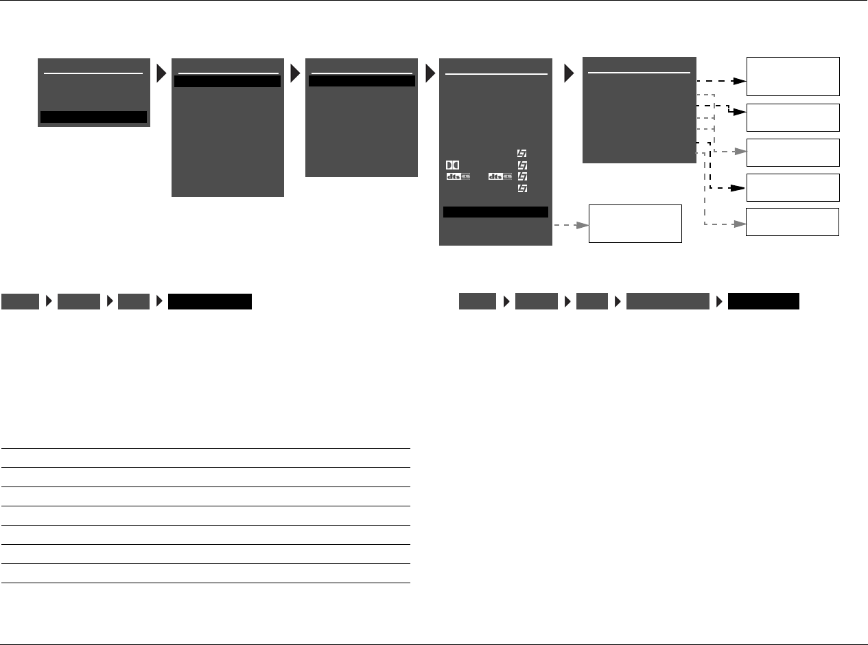
RV-5 Setup
3-15
CONFIGURING ADVANCED VIDEO SETTINGS
MAIN ADVANCED
Selecting the INPUT SETUP menu MAIN ADVANCED option opens
the MAIN ADV menu shown above. The parameters on the left side
of this menu are identical, regardless of which input is selected. The
settings on the right side are adjustable. Default parameter settings
differ from input to input.
INPUT SELECT DIGITAL, ANALOG, AUTO
Controls the interaction of the digital and analog audio input
connectors assigned to the current Main Zone input. The INPUT
SETUP menu is used to assign one digital and one analog audio input
connector for the selected input. The table on page 3-17 describes
INPUT SELECT parameter settings.
Note:
When the INPUT SELECT parameter is set to AUTO, the RV-5 will not select
the assigned analog audio input connector when a valid digital audio
input source is present. Some DVD and CD players output digital signals
(data) when the player is paused or stopped or when the player is
powered on and the disc drawer is empty. When this occurs, the RV-5
automatically selects the assigned digital audio input connector.
DVD1 MAIN ADV
INPUT SELECT
ANALOG BYPASS
S-VIDEO 16:9
S-VIDEO OSD 4:3
COMPONENT OSD
DIGITAL
OFF
AUTO
ON
OFF
DIGITAL
ANGL
DMIX
DIGITAL
ANALOG
AUTO
AUTO
OFF
ON
OFF
DVD1 INPUT SETUP
NAME
DIGITAL IN
ANALOG IN
VIDEO IN
COMPONENT IN
2-CH
MIC
D
DVD1
COAX-1
NONE
AUTO
S-VIDEO-1
1
FILM
5.1 FILM
FILM
ANLG IN LVL
LIVE! MED
MAIN ADVANCED
ZONE2 IN DIGITAL
ZONE2 ADVANCED
5.1a FILM
5.1a
INPUT SETUP
DVD2
TV
SAT
VCR
CD
TUNER
PHONO
DVD1
MAIN MENU
MODE ADJUST
AUDIO CONTROLS
TUNER PRESETS
SETUP
SETUP
INPUTS
SPEAKERS
I/O CONFIG
DISPLAYS
VOLUME CONTROLS
TRIGGER
LOCK OPTIONS
LIVE! CALIBRATION
TUNER SETUP
LEGACY VIDEO
POWER MANAGEMENT
FORMAT DETECT FAST
A
B
NORMAL
FAST
A
Parameter Possible Settings
INPUT SELECT DIGITAL, ANALOG, AUTO
ANLOG BYPASS ON, OFF
S-VIDEO 16:9 AUTO, OFF
S-VIDEO OSD 4:3 ON, OFF
COMPONENT OSD ON, OFF
LEGACY VIDEO A, B
FORMAT DETECT NORMAL, FAST
INPUTSSETUP DVD1 MAIN ADVANCED INPUTSSETUP DVD1 MAIN ADVANCED INPUT SELECT

Setup Lexicon
3-16
CONFIGURING ADVANCE INPUT SETTINGS (continued)
ANALOG BYPASS ON, OFF
When set to ON, the RV-5 passes the analog input signal to the Main
Zone audio output connectors. For stereo analog sources, the input is
sent to the FRONT L/R outputs. For a 5.1-channel analog source, the
(L) input is sent to the FRONT L output. The (R) input is sent to the
FRONT R output. The (C) input is sent to the center output. The
(SUB) input is sent to the SUB output. The (LS) input is sent to the
SIDE L and REAR L outputs. The (RS) input is sent to the SIDE R and
REAR R outputs. When ANALOG BYPASS is set to OFF, the unit routes
the analog input signal through A/D conversion. This makes it
possible to utilize internal processing, including listening modes,
crossovers and equalization. Neither Zone 2 nor Zone 3 provide
multichannel outputs. If the 5.1-channel analog input is selected for
Zone 2 or Zone 3, only the front left and right (L)/(R) inputs will be
available.
When LIVE! is the selected analog input, the MAIN ADVANCED
INPUT SELECT parameter is forced to ANALOG, and ANALOG
BYPASS is disabled.
Note:
If the Main Zone source is 5.1 analog, only the Front L/R channels will be
sent to the Zone 2 S/PDIF outputs.
S-VIDEO 16:9 AUTO, OFF
Controls the passage of anamorphic trigger signals present in some
video sources. When set to AUTO, the RV-5 allows anamorphic video
input signals to pass through the S-Video switcher, enabling
compatible display devices to automatically switch between
anamorphic and non-anamorphic display modes.
When OFF, the RV-5 prevents anamorphic video input signals from
passing through the S-Video switcher, preventing compatible
display devices from automatically switching between anamorphic
and non-anamorphic display modes.
INPUTSSETUP DVD1 MAIN ADVANCED ANALOG BYPASS INPUTSSETUP DVD1 MAIN ADVANCED S-VIDEO 16:9
RV-5 Setup
3-17
INPUT SELECT PARAMETER SETTINGS
DIGITAL ANALOG AUTO
The RV-5 sends the assigned digital audio
input connector to the Main Zone audio
output connectors. The RV-5 ignores the
assigned analog audio input connector.
Note the following:
• The digital audio input connectors
are compatible with PCM (44.1, 48,
88.2 and 96kHz), Dolby Digital and
DTS(-ES) sources.
• The digital audio input connectors
are not compatible with MPEG or
MP3 sources. If an incompatible
digital audio source (e.g., MPEG or
MP3) is present, the RV-5 automati-
cally selects the assigned analog
audio input connector.
• The RV-5 automatically sets the
INPUT SELECT parameter to DIGITAL
when the ANALOG IN parameter is
set to NONE.
• If ANALOG IN is set to NONE, the
RV-5 will mute.
•The DIGITAL IN parameter can be
used to assign a digital audio input
connector for the selected input.
The RV-5 sends the assigned analog audio input
connector to the Main Zone audio output
connectors. The RV-5 ignores the digital audio
input connector.
Note the following:
• The RV-5 automatically sets the INPUT
SELECT parameter to ANALOG when the
DIGITAL IN parameter is set to NONE.
• The ANALOG IN parameter can be used to
assign an analog audio input connector
for the selected input.
The RV-5 toggles between sending the assigned
digital and analog audio input connectors to the
Main Zone audio output connectors, based on the
input source that is present.
For example:
• When a 2-channel PCM, Dolby Digital or
DTS(-ES) source is present, the RV-5
automatically selects the assigned digital
audio input connector.
•When an SACD
TM source is present, the RV-
5 automatically selects the assigned analog
audio input connector.
Note the following:
• The RV-5 automatically sets the INPUT SELECT
parameter to AUTO when both digital and
analog audio input connectors are assigned.
• When no compatible digital source is
present, the RV-5 automatically selects the
assigned analog audio input connector.
• The AUTO setting is recommended for
components that generate both digital and
analog input signals, such as DVD/SACD
players.
Setup Lexicon
3-18
CONFIGURING ADVANCE INPUT SETTINGS (continued)
S-VIDEO OSD 4:3 ON, OFF
Controls the appearance of the on-screen display when the display
device is connected to an S-Video output connector. When set to
ON, the display device shows the on-screen display in a 4:3 aspect
ratio, regardless of the incoming signal.
Aspect ratio refers to the ratio between the height and width of the
picture on the display device or to the ratio between the height and
width of the display device. A 4:3 aspect ratio is almost square. A
16:9 aspect ratio, often referred to as “widescreen,” is almost twice as
wide as it is high.
When OFF, the display device shows the on-screen display in the
same aspect ratio as the incoming video input signal.
Note:
The on-screen display appears horizontally stretched across the display
device screen when all of the following conditions are present:
• The S-VIDEO OSD 4:3 parameter is OFF.
• An anamorphic video input signal is present.
• A 16:9 display device (widescreen) is connected to an S-Video
output connector.
COMPONENT OSD ON, OFF
Controls the appearance of the on-screen display when the display
device is connected to the component video output connector.
When ON, the display device shows the on-screen display as a 480i
video signal on a full blue-screen background. To minimize viewing
distractions, the two-line status does not appear in the on-screen
display. When OFF, the display device does not show the on-screen
display, including the two-line status.
Note:
When the ON-SCREEN DISPLAY menu BACKGROUND parameter is OFF,
the display device using the component video output connector will not
show the on-screen display.
INPUTSSETUP DVD1 MAIN ADVANCED S-VIDEO OSD 4-3
INPUTSSETUP DVD1 MAIN ADVANCED COMPONENT OSD
RV-5 Setup
3-19
LEGACY VIDEO A, B
When video played back from a VCR is converted to component
video by the RV-5, the resulting picture quality depends on both the
quality of the VCR playback and the capabilities of the component
display device. The LEGACY VIDEO menu item has two selections, A
and B. Use the one that gives the best picture for the Combination of
the VCR and display device.
Note:
Some combinations of VCR and display device may not produce a
satisfactory picture with either setting. In such cases, better results may be
achieved by connecting to the display device via composite or S-video.
FORMAT DETECT NORMAL, FAST
Controls how the RV-5 reacts when it detects silence in the digital
audio stream. Digital sources typically output a short period of silence
when switching between sources.
When set to NORMAL, the RV-5 will not mute when silence is
detected. This setting is appropriate for most sources.
When set to FAST, the RV-5 will mute when approximately 2ms of
continuous digital silence is detected. Once valid audio is received,
the RV-5 will configure its processing and deactivate mute. This
prevents digital noise from occurring during digital audio signal
changes. For example, when switching from Dolby Digital to DTS.
Use this setting if audible noise occurs during input digital format
changes.
ZONE2 IN DIGITAL, ANLG, DMIX
Controls the interaction of the digital and analog audio input
connectors assigned to the current Zone 2 inputs. The INPUT SETUP
menu can be used to assign one digital and one analog input
connector for the selected input. See page 3-7 for more information.
The table on the next page describes ZONE2 IN parameter settings.
Note
When using DTS-encoded discs, set the ZONE2 IN parameter to DMIX.
When the ZONE2 IN parameter is set to DIGITAL, the unit recognizes
DTS-encoded discs as audio signals (not data signals) and outputs
loud digital noise from the ZONE2 analog and digital audio outputs.
For maximum flexibility with Dolby Digital and DTS (-ES) sources:
1. Select a Main Zone DIGITAL IN connector.
2. Set the ZONE2 IN parameter to ANLG.
3. Connect the digital and analog outputs on the DVD player to the
corresponding digital and analog inputs on the RV-5.
The unit will use the digital connector for the Main Zone, and the
analog connectors for Zone 2.
INPUTSSETUP DVD1 MAIN ADVANCED LEGACY VIDEO
INPUTSSETUP DVD1 MAIN ADVANCED FORMAT DETECT
INPUTSSETUP DVD1 ZONE2 IN
Setup Lexicon
3-20
ZONE2 IN PARAMETER SETTINGS
DIGITAL ANLG (Analog) DMIX (Downmix)
• The RV-5 automatically sets
the ZONE2 IN parameter to
DIGITAL when the ANALOG
IN parameter is set to NONE.
• The RV-5 sends the assigned
DIGITAL IN connector
specified in the INPUT SETUP
menu to the ZONE 2
ANALOG and DIGITAL AUDIO
OUTPUTS.
• Only PCM digital input
sources are compatible with
ZONE 2 analog audio
outputs. Dolby Digital and
DTS sources are compatible
with the Zone 2 digital audio
output when the DIG BYPASS
parameter is set to ON.
• Audio will not be available in
Zone 2 analog outputs when
a Dolby Digital, DTS (-ES) or
unknown digital input source
is present.
• The ANALOG IN connector
specified in the INPUT SETUP
menu is sent to the ZONE 2
ANALOG and DIGITAL AUDIO
OUTPUTS.
• Only Front L/R Audio will be
available in Zone 2 when one
of the 5.1 analog inputs is
selected for the Main Zone.
• Set the ZONE2 IN parameter to DMIX to send a downmixed
version of Main Zone audio to the Zone 2 audio output
connectors. Downmixes can be generated for Dolby Digital,
DTS(-ES) and 5.1a sources.
• To generate a downmix, the same input must be selected in
the Main Zone and Zone 2. Otherwise, the Zone 2 audio
output connectors will mute.
• Main Zone listening mode activation affects the Zone 2 audio
output connectors. For instance, when the MONO listening
mode is activated in the Main Zone, the Zone 2 audio output
connectors will generate mono output signals.
• It is recommended that you set the ZONE2 IN parameter to
DMIX when recording from a DVD player without built-in
Dolby Digital or DTS-ES decoding to a VCR or PVR (e.g. Tivo®
or Replay TV®).
• A 2-channel downmixed version of Main Zone audio is sent to
the ZONE 2 ANALOG and DIGITAL AUDIO OUTPUTS.
Downmixes can be generated for Dolby Digital, DTS(-ES) and
5.1 analog input sources. To generate a downmix, the input
that is selected in Zone 2 must also be selected in the Main
Zone (e.g., DVD1). Otherwise, the ZONE 2 ANALOG and
DIGITAL AUDIO OUTPUTS will mute. Downmixes cannot be
generated when the 5.1a BYPASS listening mode is selected in
the Main Zone.
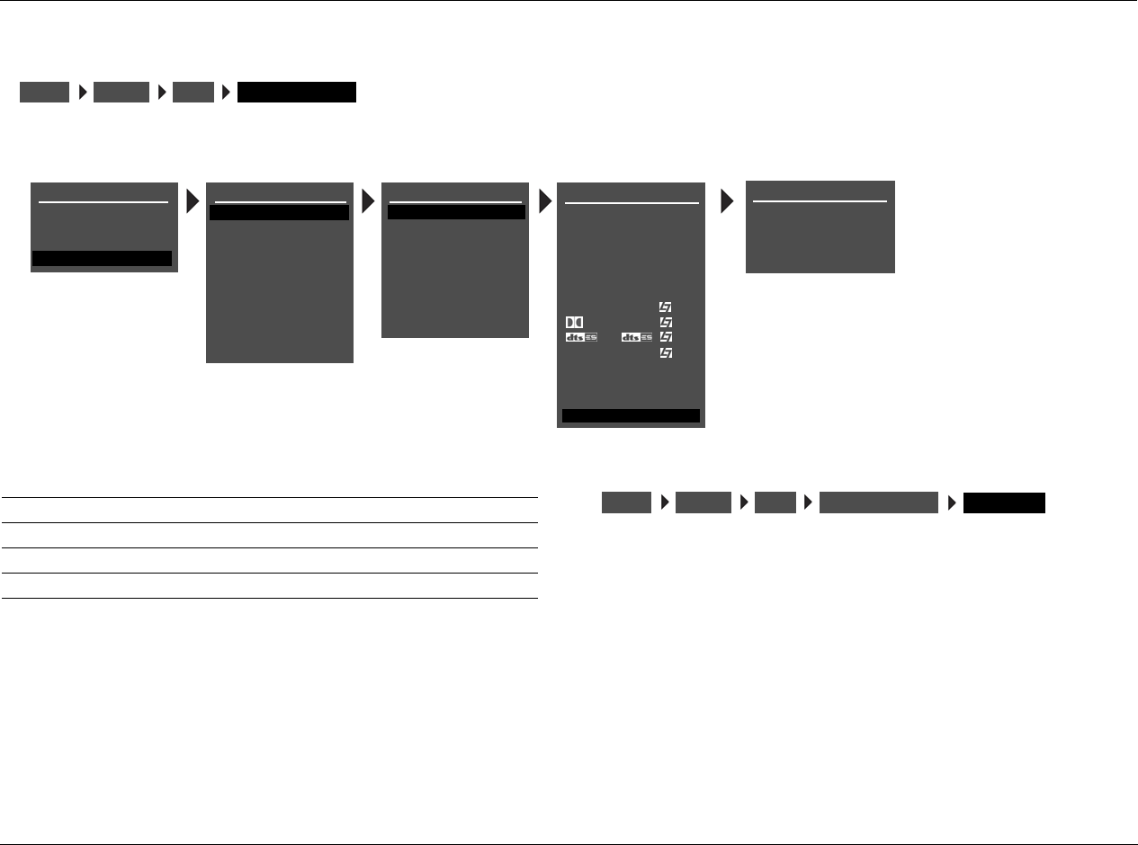
RV-5 Setup
3-21
ZONE2 ADVANCED
Opens the ZONE2 IN menu, which is used to configure advanced
ANLG IN LVL -18 to +12dB
Allows adjustment of analog audio input levels for input signals sent
to the Zone 2 digital audio output connectors. The RV-5 applies these
adjustments to input signals before passing them to the Zone 2
digital audio output connectors. This parameter can be adjusted
when an input source is present to prevent the internal A/D converter
from overloading.
INPUTSSETUP DVD1 ZONE2 ADVANCED
DVD1 ZONE2 ADVANCED
ANLG IN LVL
DIGITAL BYPASS
DIG OUT RATE
RECORD
+0dB
OFF
44.1kHz
ENABLED
DVD1 INPUT SETUP
NAME
DIGITAL IN
ANALOG IN
VIDEO IN
COMPONENT IN
2-CH
MIC
D
DVD1
COAX-1
NONE
AUTO
S-VIDEO-1
1
FILM
5.1 FILM
FILM
ANLG IN LVL
LIVE! MED
MAIN ADVANCED
ZONE2 IN DIGITAL
ZONE2 ADVANCED
5.1a FILM
5.1a
INPUT SETUP
DVD2
TV
SAT
VCR
CD
TUNER
PHONO
DVD1
MAIN MENU
MODE ADJUST
AUDIO CONTROLS
TUNER PRESETS
SETUP
SETUP
INPUTS
SPEAKERS
I/O CONFIG
DISPLAYS
VOLUME CONTROLS
TRIGGER
LOCK OPTIONS
LIVE! CALIBRATION
TUNER SETUP
POWER MANAGEMENT
Parameter Possible Settings
ANLG IN LVL -18dB to + 12dB
DIGITAL BYPASS ON, OFF
DIG OUT RATE 96kHz, 88.2kHz, 48kHz, 44.1kHz
RECORD BLOCKED, ENABLED
INPUTSSETUP DVD1 ZONE2 ADVANCED ANLG IN LVL
Setup Lexicon
3-22
DIGITAL BYPASS ON, OFF
Allows digital sources to bypass decoding for direct digital recording.
When ON is selected, the RV-5 passes digital input signals directly to
the Zone 2 digital audio output connectors, preserving the original
format of the input signal. This would be useful if you want to send a
multichannel-encoded signal to a second device for decoding. When
OFF is selected and the ZONE2 IN parameter is set to DIGITAL, Dolby
Digital and DTS sources will not be passed to the Zone 2 digital audio
outputs. When OFF is selected and a PCM source is present, the RV-5
will send the PCM audio to the Zone 2 digital audio output
connectors. If a Dolby Digital or DTS source is present and the
ZONE2 IN parameter is set to DMIX, a downmix of the source will be
sent to the Zone 2 digital audio output connectors.
DIG OUT RATE 96kHz, 88.2kHz, 48kHz, 44.1kHz
Controls the sample rate of analog input signals sent to the Zone 2
digital audio output connectors.
When a value is selected, the RV-5 runs the Zone 2 A/D converters at
the selected sample rate. It is recommended to set the DIG OUT RATE
parameter to the appropriate value when using a recording format
that operates on a single sample rate, such as CD-R format (44.1kHz).
Note:
DIG OUT RATE only affects analog input signals. It does not change the
sample rate of digital input signals, or downmixed signals.
RECORD BLOCKED, ENABLED
Prevents recording device feedback loops. When BLOCKED is
selected, the RV-5 blocks the Zone 2 audio output connectors to
prevent feedback loops. However, the RV-5 still passes video input
signals to the Zone 2 video output connectors. When ENABLED is
selected, the RV-5 passes audio and video input signals to the Zone 2
audio and video output connectors.
INPUTSSETUP DVD1 ZONE2 ADVANCED DIGITAL BYPASS
INPUTSSETUP DVD1 ZONE2 ADVANCED DIG OUT RATE
INPUTSSETUP DVD1 ZONE2 ADVANCED RECORD
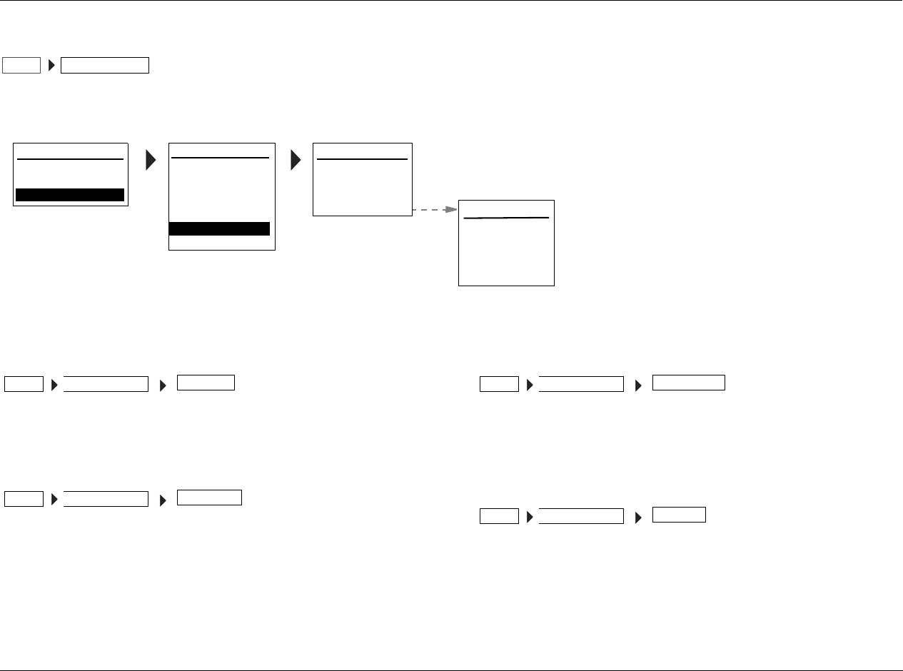
RV-5 Setup
3-23
SPEAKER/EQ SETUP
Select the SPEAKER SETUP menu to configure the Main Zone audio output connectors for the desired speaker setup. The Main Zone includes eight
audio output connectors labeled Front L/R, Center, Subwoofer, Side L/R and Rear L/R.
REAR AMP REAR SPK, ZONE 2
Selects the REAR AMP menu, which....
AUTOMATIC
Selects the AUTOMATIC menu, which controls the automatic
selection of crossover frequencies, channel adustments, delay
adjustments, and room equalization parameters.
AUTO EQ ONLY
Selects the AUTO EQ ONLY menu, which controls the automatic
selection of the EQ.
MANUAL
Allows the user to manually make the selections for both speaker and
EQ setup.
SPEAK/EQ SETUPSETUP
MAIN MENU
AUDIO CONTROLS
VIDEO CONTROLS
SETUP 7.1 SETUP:
SURROUND CONFIG
DOLBY CONFIG
POWER ON SETTINGS
5.1+DSP
SETUP
INPUT SETUP
DISPLAY SETUP
SPEAK/EQ SETUP
REAR AMP:
AUTOMATIC
AUTO EQ ONLY
MANUAL
REAR SPK
MANUAL SPEAKER/EQ
SPEAKERS
SPEAKER DISTANCES
SPEAK/EQ SETUP
OUTPUT LEVELS
AUTO EQ: OFF
ADJUST EQ OFF
SPEAK/EQ SETUPSETUP REAR AMP
SPEAK/EQ SETUPSETUP AUTOMATIC
SPEAK/EQ SETUPSETUP AUTO EQ ONLY
SPEAK/EQ SETUPSETUP MANUAL
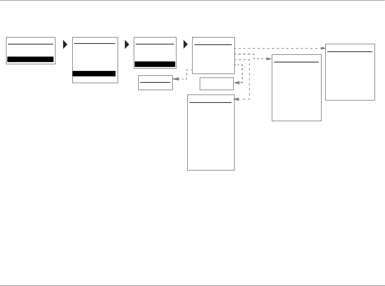
Setup Lexicon
3-24
SPEAKER SETUP PARAMETERS (continued)
MAIN MENU
AUDIO CONTROLS
VIDEO CONTROLS
SETUP 7.1 SETUP:
SURROUND CONFIG
DOLBY CONFIG
POWER ON SETTINGS
5.1+DSP
SETUP
INPUT SETUP
DISPLAY SETUP
SPEAK/EQ SETUP
REAR AMP:
AUTOMATIC
AUTO EQ ONLY
MANUAL
REAR SPK SPEAKERS
AUTO SETTINGS:
FRONT L/R:
OFF
80 Hz
SPEAK/EQ SETUP
CENTER: 80 Hz
SIDE L/R: 80 Hz
REAR/Z2 L/R: 80 Hz
MANUAL
SUBWOOFERS: 1
SUB HPF: 20 Hz
SUB/LFE LPF: 80 Hz
SUB MODE: LFE ONLY
MANUAL SPEAKER/EQ
SPEAKERS
SPEAKER DISTANCES
OUTPUT LEVELS
AUTO EQ: OFF
ADJUST EQ
OUTPUT LEVELS
AUTO SETTINGS:
INPUT:
OFF
TEST TONE:
SPEAKER DISTANCES
AUTO SETTINGS:
UNITS:
OFF
FEET
FRONT LEFT: 12.0
CENTER: 12.0
FRONT RIGHT:
SIDE RIGHT:
REAR RIGHT:
REAR LEFT:
SIDE LEFT:
SUBWOOFERS: 80 Hz
RESTORE DEFAULTS: NO
12.0
12.0
12.0
12.0
12.0
ON
OFF
ADJUST EQ
TILT: OdB
FRONT LEFT:
CENTER:
FRONT RIGHT:
SIDE RIGHT:
REAR RIGHT:
REAR LEFT:
SIDE LEFT:
SUBWOOFER 1:
RESTORE DEFAULTS: NO
SUBWOOFER 2: 0dB
+10dB
- - -
- - -
+10dB
0dB
ALL
+5dB
+10dB
+5dB
OFF
RV-5 Setup
3-25
AUTO EQ OFF, ON
Selects the AUTO EQ menu, which controls the automatic EQ
controls.
TILT -8 TO +8DB
Selects the TILT menu, which controls.....
Note:
It is important to set crossover points before calibrating output levels or
LIVE!. Setting crossover points afterwards could invalidate calibrated out-
put levels and will invalidate the LIVE! calibration.
ANALOG BYPASS ON, OFF
When set to ON, the RV-5 passes the analog input signal to the Main
SPEAK/EQ SETUPSETUP MANUAL AUTO EQ
SPEAK/EQ SETUPSETUP MANUAL ADJUST EQ TILT
INPUTSSETUP DVD1 MAIN ADVANCED ANALOG BYPASS
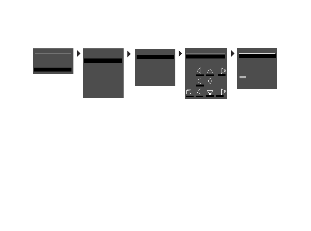
Setup Lexicon
3-26
CUSTOM SPEAKER SETUPS
Selecting the CROSSOVER SETUP menu CUSTOM SETUP option opens the CUSTOM SETUP menu, which assigns independent crossover points for
each Main Zone audio output connector. Possible crossover settings include FULL, FULL + SUB, and 10Hz increments within a 30Hz to 120Hz
range. The graphs shown on the next page indicate the frequency response of each crossover point.
To configure a custom speaker setup:
• Select the crossover point closest to the low frequency rating of
the associated speakers. For example, set the FRONT L/R
parameter to the crossover point closest to the low-frequency
rating of the front speakers.
• Select the subwoofer crossover point equal to the lowest
crossover point of any of the other speakers. For example, if
CUSTOM SETUP menu parameters are set as shown above, set
the SUBWOOFER parameter to 40Hz – the lowest crossover
point of the other speakers.
In a custom setup, low frequencies are generally redirected from
speakers with the highest crossover points to speakers with the
lowest crossover points. Signals lower than the lowest crossover point
are redirected to the subwoofer. If the lowest crossover point is FULL,
low-frequency signals, excluding LFE information, are not redirected
to the subwoofer.
Low frequencies between the Subwoofer and any or all of the other
speaker channels can be duplicated. To do this, select the FULL + SUB
crossover setting for the front, center, side or rear speakers. Making
this selection can result in excessive bass.
MAIN MENU
MODE ADJUST
AUDIO CONTROLS
TUNER PRESETS
SETUP
INPUTS
SPEAKERS
I/O CONFIG
DISPLAYS
VOLUME CONTROLS
TRIGGES
TUNER SETUP
LOCK OPTIONS
LIVE! CALIBRATION
SETUP
SPEAKER SETUP
SET CROSSOVERS
CHECK MICROPHONES
AUTOMATIC
MANUAL
SET CROSSOVERS
BEFORE CALIBRATING
CROSSOVER SETUP
CUSTOM SETUP
THX SETUP
C
R SR RR
L SL RL
M
SUB
80Hz 80Hz 80Hz
80Hz
80Hz 80Hz 80Hz 80Hz
CUSTOM SETUP
FRONT L/R
CENTER
SIDE L/R
REAR L/R
ULTRA2 SUB
40 Hz
60 Hz
60 Hz
60 Hz
OFF
N/A
APART
SUBWOOFER
BGC
ASA
40 Hz
POWER MANAGEMENT
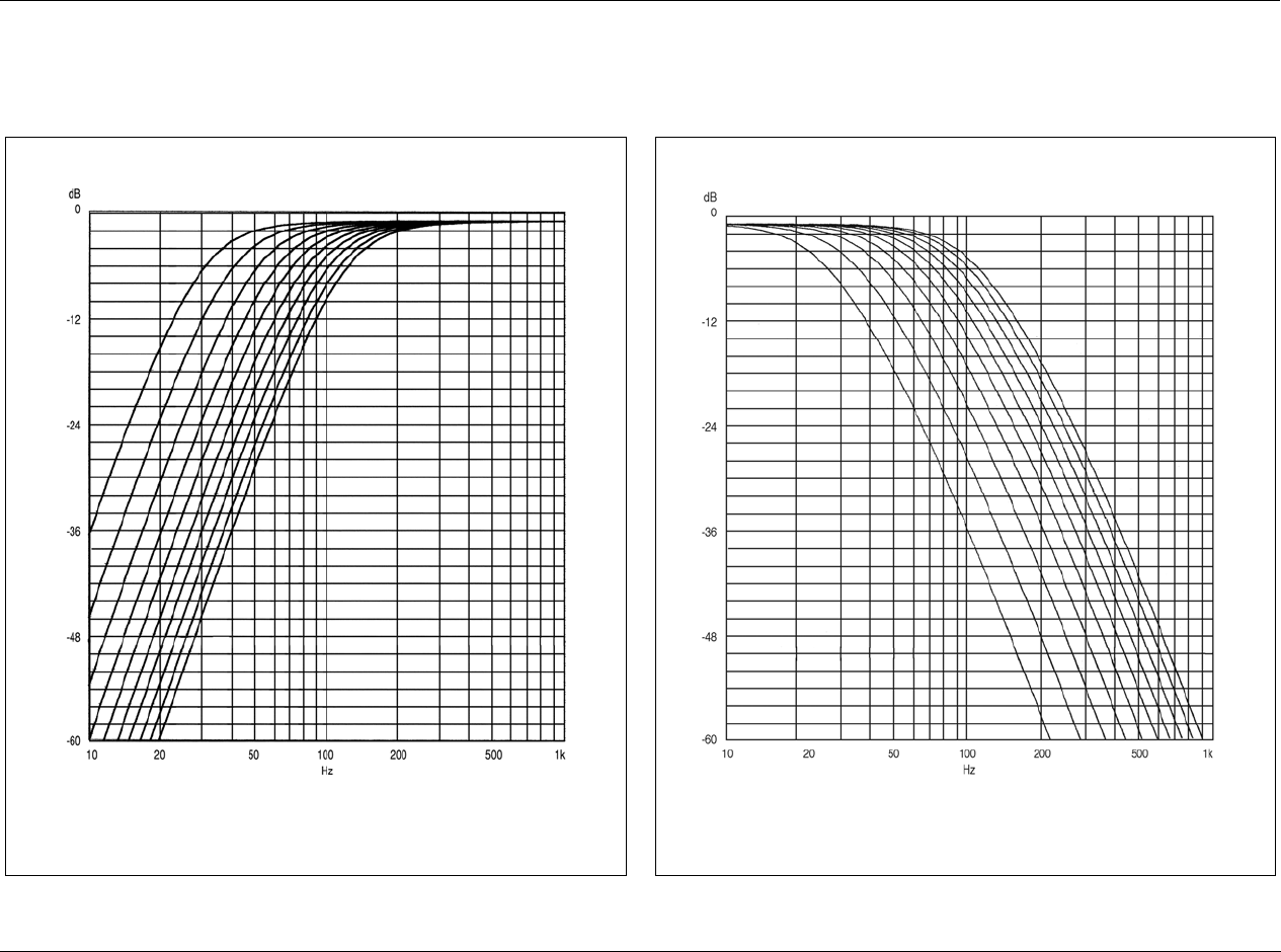
RV-5 Setup
3-27
In general, low frequencies will be redirected from speakers with the highest crossover points to speakers with the lowest crossover points. Low-
frequency signals lower than the lowest crossover point will be redirected to the subwoofer. If the lowest crossover point is FULL, low frequency
signals, excluding LFE information, will not be redirected to the subwoofer.
Low-pass filters attenuate high frequencies at 24dB per octave. The curves in the graph
above indicate the frequency response of each crossover setting. From left to right, the
curves represent crossover settings from 30Hz to 120Hz.
High-pass filters attenuate low frequencies at 24dB per octave. The curves in the graph
above indicate the frequency response of each crossover setting. From left to right, the
curves represent crossover settings from 30Hz to 120Hz. The graph above does not
show the THX 80Hz crossover point, which is 12dB per octave.
High-Pass Filter Low-Pass Filter
Setup Lexicon
3-28
SPEAKER SETUP PARAMETERS
The table below indicates the speaker setup parameters for config-
uring the Main Zone audio output connectors for the desired speaker
setup. These parameters are available in the CUSTOM SETUP and
THX SETUP menus.
Speaker setup parameters perform the same function regardless of
the selected speaker setup. When a parameter setting is adjusted on
one menu, the corresponding parameter setting is automatically
adjusted on the other menu. For example, when a THX speaker setup
is selected, the crossover settings on the CUSTOM SETUP menu are
set to THX 80Hz.
* These parameters cannot be adjusted on the THX SETUP menu.
† When the THX ULTRA2 SUB parameter is set to OFF, the BGC parameter is not available (N/A).
SPEAKERSSETUP CUSTOM SETUP or
SPEAKERSSETUP THX SETUPSET CROSSOVERS SET CROSSOVERS
Parameter
CUSTOM SETUP Menu THX SETUP Menu
Default Setting Possible Settings Default Setting Possible Settings
FRONT L/R* 80Hz FULL, FULL + SUB, 30 to 120Hz, THX 80Hz THX 80Hz THX 80Hz
CENTER* 80Hz FULL, FULL + SUB, 30 to 120Hz, THX 80Hz, NONE THX 80Hz THX 80Hz
SIDE L/R* 80Hz FULL, FULL + SUB, 30 to 120Hz, THX 80Hz, NONE THX 80Hz THX 80Hz
REAR L/R 80Hz FULL, FULL + SUB, 30 to 120Hz, THX 80Hz, NONE THX 80Hz THX 80Hz, NONE
SUBWOOFER* 80Hz FULL, 30 to 120Hz, THX 80Hz, NONE THX 80Hz THX 80Hz
THX ULTRA2 SUB OFF ON, OFF OFF ON, OFF
BGC N/A† ON, OFF N/A† ON, OFF
ASA APART APART, CLOSE, TOGETHER APART APART, CLOSE, TOGETHER
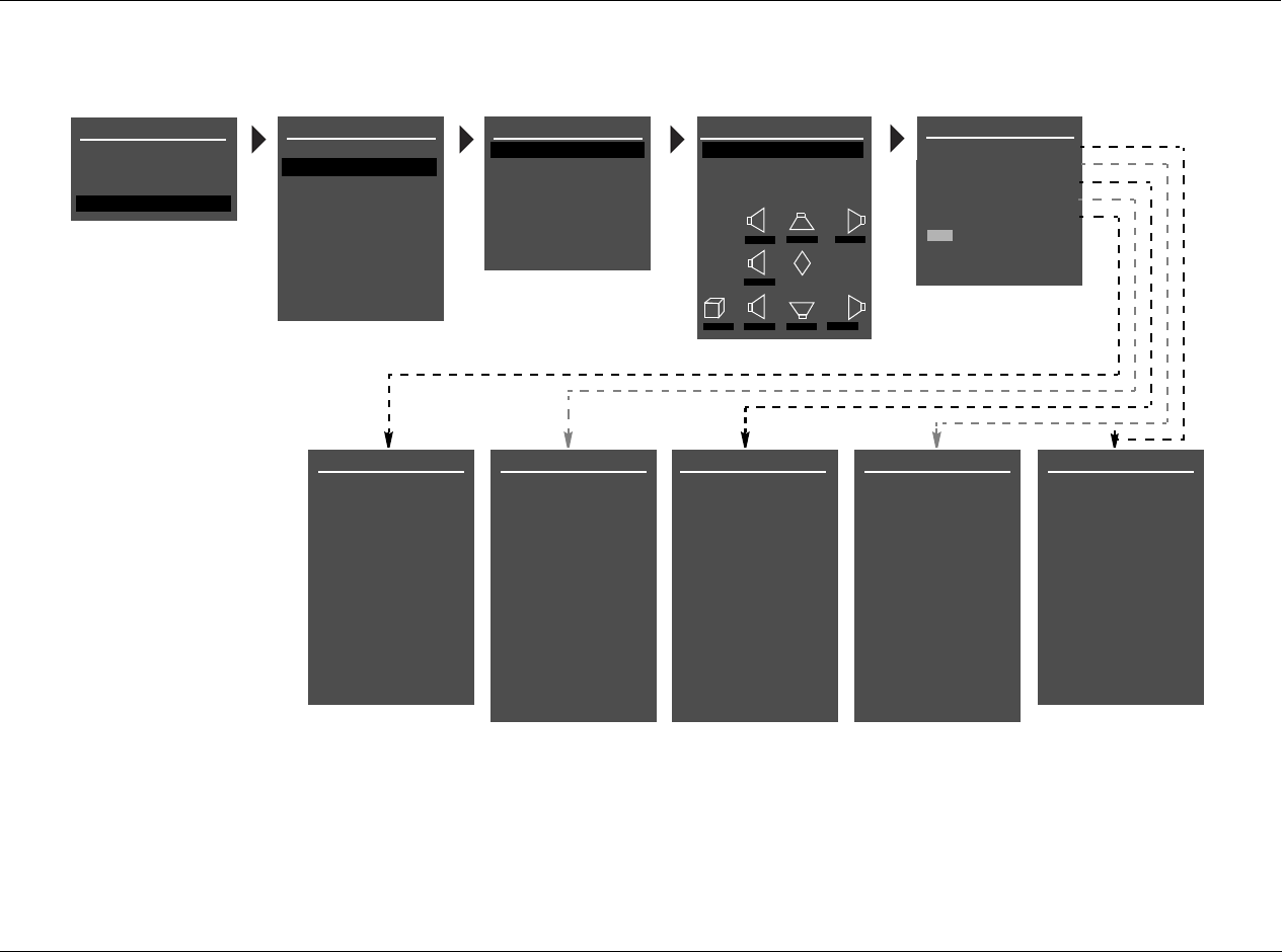
RV-5 Setup
3-29
SPEAKER SETUP PARAMETERS (continued)
MAIN MENU
MODE ADJUST
AUDIO CONTROLS
TUNER PRESETS
CROSSOVER SETUP
CUSTOM SETUP
THX SETUP
C
R SR RR
L SL RL
M
SUB
80Hz 80Hz 80Hz
80Hz
80Hz 80Hz 80Hz 80Hz
SETUP
INPUTS
SPEAKERS
I/O CONFIG
DISPLAYS
VOLUME CONTROLS
TRIGGER
TUNER SETUP
LOCK OPTIONS
CUSTOM SETUP
FRONT L/R
CENTER
SIDE L/R
REAR L/R
ULTRA2 SUB
40Hz
60Hz
60Hz
60Hz
OFF
N/A
APART
SUBWOOFER
BGC
ASA
40Hz
LIVE! CALIBRATION
SETUP
SUBWOOFER
FULL
30Hz
40Hz
50Hz
60Hz
70Hz
80Hz
THX 80 Hz
90Hz
100Hz
110Hz
120Hz
REAR L/R SPEAKERS
FULL
30Hz
40Hz
50Hz
60Hz
70Hz
80Hz
THX 8 0Hz
90Hz
100Hz
110Hz
120Hz
NONE
SIDE L/R SPEAKERS FRONT L/R SPEAKERSCENTER SPEAKER
NONE
FULL + SUB
FULL
30Hz
40Hz
50Hz
60Hz
70Hz
80Hz
THX 80Hz
90Hz
100Hz
110Hz
120Hz
NONE
FULL + SUB
FULL
30Hz
40Hz
50Hz
60Hz
70Hz
80Hz
THX 80 Hz
90Hz
100Hz
110Hz
120Hz
NONE
FULL + SUB
FULL
30Hz
40Hz
50Hz
60Hz
70Hz
80Hz
THX 80 Hz
90Hz
100Hz
110Hz
120Hz
FULL + SUB
SPEAKER SETUP
SET CROSSOVERS
CHECK MICROPHONES
AUTOMATIC
MANUAL
SET CROSSOVERS
BEFORE CALIBRATING
POWER MANAGEMENT

Setup Lexicon
3-30
FRONT L/R FULL, FULL + SUB, 30 to 120HZ, THX 80HZ
Assigns a crossover point for the Main Zone audio output connectors
labeled Front L/R when a custom speaker setup is selected. Opens the
FRONT L/R SPEAKERS menu to select a crossover point for the Front
L/R output connectors.
•Select FULL to send a full-range signal to the front speakers.
Otherwise, select the crossover point closest to the low-
frequency rating of the front speakers.
•Select FULL + SUB to send a full-range signal to the front
speakers and duplicate bass frequencies to the SUB output.
(The set crossover point of the SUB parameter determines the
upper range of duplicate bass.) Selecting the FULL + SUB
option can result in excessive bass.
When THX speaker setup is selected, a THX 80Hz crossover point is
applied to the Front L/R output connectors, and the FRONT L/R
parameter cannot be adjusted.
CENTER FULL, FULL + SUB, 30 to 120HZ, THX 80HZ, NONE
Assigns a crossover point for the Main Zone audio output connector
labeled CENTER when a custom speaker setup is selected. Opens the
CENTER SPEAKER menu to select a crossover point for the CENTER
output connector.
• Select FULL to send a full-range signal to the center speaker.
Otherwise, select the crossover point closest to the low-
frequency rating of the center speaker.
• Select FULL + SUB to send a full-range signal to the center
speaker and duplicate bass frequencies to the SUB output. (The
set crossover point of the SUB parameter determines the upper
range of duplicate bass.) Selecting the FULL + SUB option can
result in excessive bass.
• When the speaker setup does not include a center speaker, select
NONE to redirect center channel signals to the Front L/R output
connectors – unless the 5.1a BYPASS listening mode is activated. In
this case, configure the speaker setup with the associated DVD-A/
SACD player to redirect center channel signals.
When THX speaker setup is selected, a THX 80Hz crossover point is
applied to the Center output connector, and the CENTER parameter
cannot be adjusted.
SPEAKERSSETUP CUSTOM SETUP FRONT L/RSET CROSSOVERS
SPEAKERSSETUP SET CROSSOVERS THX SETUP
SPEAKERSSETUP CUSTOM SETUP CENTERSET CROSSOVERS
SPEAKERSSETUP SET CROSSOVERS THX SETUP

RV-5 Setup
3-31
SPEAKER SETUP PARAMETERS (continued)
SIDE L/R FULL, FULL + SUB, 30 to 120Hz, THX 80Hz, NONE
Assigns a crossover point for the Main Zone audio output connectors
labeled SIDE L/R when a custom speaker setup is selected.
•Select FULL to send a full-range signal to the side speakers.
Otherwise, select the crossover point closest to the low-
frequency rating of the side speakers.
•Select FULL + SUB to send a full-range signal to the side
speakers and duplicate bass frequencies to the SUB output.
(The set crossover point of the SUB parameter determines the
upper range of duplicate bass.) Selecting the FULL + SUB option
can result in excessive bass.
• When the speaker setup does not include side speakers, select
NONE to redirect side channel signals to the Rear L/R output
connectors. If the REAR L/R parameter is also set to NONE, the
RV-5 will redirect surround channel signals to the Front L/R
output connectors.
Note:
When the SIDE L/R parameter is set to NONE, Dolby Digital Surround
EX, THX Ultra2, THX Surround EX, DTS(-ES) decoding, the ASA
parameter and PLIIx modes are not available.
When THX speaker setup is selected, a THX 80Hz crossover point is
applied to the SIDE L/R output connectors, and the SIDE L/R
parameter cannot be adjusted.
REAR L/R FULL, FULL + SUB, 30 to 120Hz, THX 80Hz, NONE
Assigns a crossover point for the Main Zone audio output connectors
labeled REAR L/R when a custom speaker setup is selected.
• Select FULL to send a full-range signal to the rear speakers.
Otherwise, select the crossover point closest to the low-
frequency rating of the rear speakers.
• Select FULL + SUB to send a full-range signal to the rear
speakers and duplicate bass frequencies to the SUB output.
(The set crossover point of the SUB parameter determines the
upper range of duplicate bass.) Selecting the FULL + SUB option
can result in excessive bass.
• When the speaker setup does not include rear speakers, select
NONE
to redirect rear channel signals to the Side L/R output connectors. If
the SIDE L/R parameter is also set to NONE, the RV-5 redirects
surround channel signals to the Front L/R output connectors.
Note:
When the REAR L/R parameter is set to NONE, Dolby Digital Surround EX,
THX Ultra2, THX Surround EX, PLIIx modes, DTS(-ES) decoding and the ASA
parameter are not available.
When THX speaker setup is selected, the THX REAR SPEAKERS menu opens
which is used to activate or deactivate the REAR L/R output connectors.
To activate and configure the Rear L/R output connectors for a
7.1-channel THX speaker, setup select THX 80Hz. To deactivate the
Rear L/R output connectors and configure the Main Zone audio output
connectors for a 5.1-channel THX speaker setup, select NONE.
SPEAKERSSETUP CUSTOM SETUP SIDE L/RSET CROSSOVERS
SPEAKERSSETUP SET CROSSOVERS THX SETUP
SPEAKERSSETUP CUSTOM SETUP REAR L/RSET CROSSOVERS
SPEAKERSSETUP THX SETUPSET CROSSOVERS
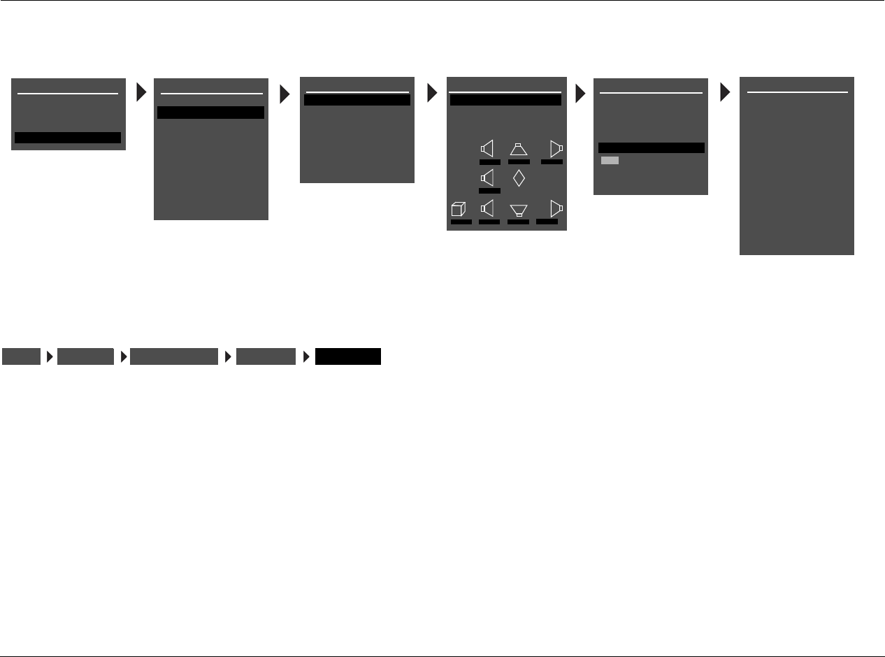
Setup Lexicon
3-32
SUBWOOFER FULL, 30 TO 120 Hz, THX 80Hz, NONE
Assigns a crossover point for the Main Zone audio output connector
labeled Subwoofer. When set to FULL, the RV-5 sends a full-range
audio output signal to this connector. Otherwise, the RV-5 activates a
crossover point at the selected setting. Choose the setting equal to
the lowest setting of the other speakers.
Note:
When the SUBWOOFER parameter is set to NONE, subwoofer signals
will not be redirected if the 5.1a BYPASS listening mode is activated. To
redirect subwoofer signals, configure the speaker setup with the
associated DVD-A/SACD player.SETUP
MAIN MENU
MODE ADJUST
AUDIO CONTROLS
SETUP
SETUP
INPUTS
SUBWOOFER
FULL
30Hz
40Hz
50Hz
60Hz
70Hz
80Hz
THX 80 Hz
90Hz
100Hz
110Hz
120Hz
NONE
CUSTOM SETUP
FRONT L/R
CENTER
SIDE L/R
REAR L/R
ULTRA2 SUB
40Hz
60Hz
60Hz
60Hz
OFF
N/A
APART
SUBWOOFER
BGC
ASA
40Hz
MAIN MENU
MODE ADJUST
AUDIO CONTROLS
TUNER PRESETS
SETUP
INPUTS
SPEAKERS
I/O CONFIG
DISPLAYS
VOLUME CONTROLS
TRIGGER
TUNER SETUP
LOCK OPTIONS
LIVE! CALIBRATION
SETUP
CROSSOVER SETUP
CUSTOM SETUP
THX SETUP
C
R SR RR
L SL RL
M
SUB
40Hz 60Hz 60Hz
60Hz
40Hz 40Hz 60Hz 60Hz
SPEAKER SETUP
SET CROSSOVERS
CHECK MICROPHONES
AUTOMATIC
MANUAL
SET CROSSOVERS
BEFORE CALIBRATING
POWER MANAGEMENT
SPEAKERSSETUP THX SETUP SUBWOOFERSET CROSSOVERS
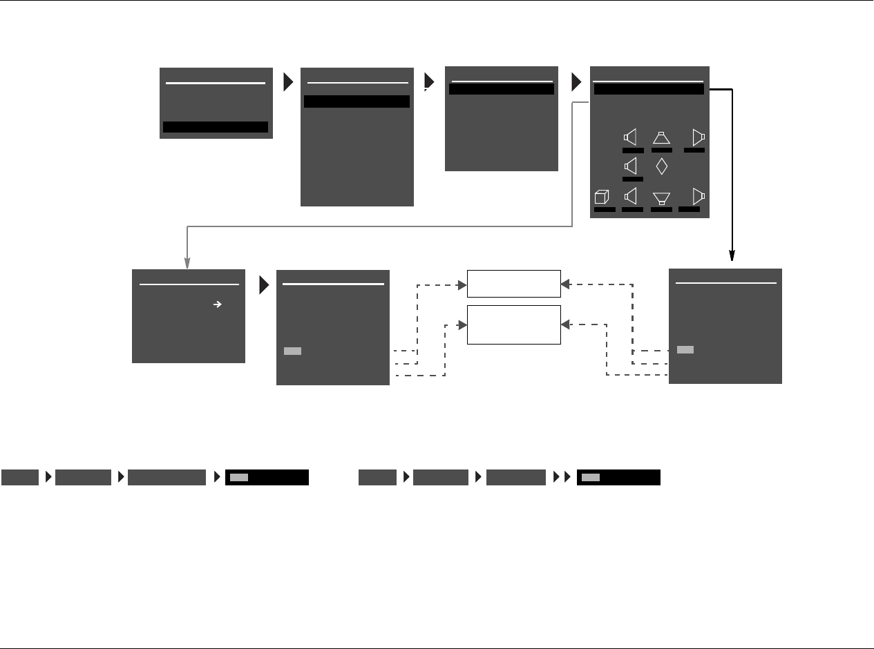
RV-5 Setup
3-33
SPEAKER SETUP PARAMETERS (continued)
THX ULTRA2 SUB ON, OFF
Indicates whether or not the subwoofer connected to the Main Zone
audio output connector labeled Subwoofer is Ultra2-certified. Select
the ON setting if the connected subwoofer is Ultra2-certified and the
OFF setting if the connected subwoofer is not Ultra2-certified. When
set to ON, the CUSTOM and THX SETUP menu BGC parameter can
be used to adjust boundary gain compensation. When set to OFF, the
BGC parameter is not available (N/A).
INPUTS
SPEAKERS
I/O CONFIG
DISPLAYS
VOLUME CONTROLS
TRIGGERS
TUNER SETUP
LOCK OPTIONS
CUSTOM SETUP
FRONT L/R
CENTER
SIDE L/R
REAR L/R
ULTRA2 SUB
40 Hz
60 Hz
60 Hz
60 Hz
OFF
N/A
APART
SUBWOOFER
BGC
ASA
40 Hz
THX SPEAKER SETUP
!CAUTION!
PRESSING THE
BUTTON WILL
AUTOMATICALLY CHANGE
THE OUTPUTS TO A THX
SPEAKER CONFIGURATION
ON
OFF
APART
CLOSE
TOGETHER
* These parameters cannot be
adjusted.
THX SETUP
FRONT L/R*
CENTER*
SIDE L/R*
REAR L/R
ULTRA2 SUB
THX 80Hz
THX 80Hz
THX 80Hz
THX 80Hz
OFF
N/A
APART
SUBWOOFER*
BGC
ASA
THX 80Hz
CROSSOVER SETUP
CUSTOM SETUP
THX SETUP
C
R SR RR
L SL RL
M
SUB
40Hz 60Hz 60Hz
60Hz
40Hz 40Hz 60Hz 60Hz
SPEAKER SETUP
SET CROSSOVERS
CHECK MICROPHONES
AUTOMATIC
MANUAL
SET CROSSOVERS
BEFORE CALIBRATING
MAIN MENU
MODE ADJUST
AUDIO CONTROLS
TUNER PRESETS
SETUP
INPUTS
SPEAKERS
I/O CONFIG
DISPLAYS
VOLUME CONTROLS
TRIGGER
TUNER SETUP
LOCK OPTIONS
LIVE! CALIBRATION
SETUP
POWER MANAGEMENT
SPEAKERSSETUP CUSTOM SETUP or
ULTRA2 SUB SPEAKERSSETUP THX SETUP ULTRA2 SUB
Setup Lexicon
3-34
BGC (BOUNDARY GAIN COMPENSATION) ON, OFF
Adjusts boundary gain compensation when the CUSTOM and THX
SETUP menu THX ULTRA2 SUB parameter is set to ON. When the
BGC parameter is set to ON, a highpass 55Hz filter is applied to all
audio output connectors for all Main Zone listening modes. When set
to OFF, no filter is applied to Main Zone listening modes and audio
output connectors. When the parameter setting is N/A, the THX
ULTRA2 SUB parameter is set to OFF, and boundary gain compen-
sation cannot be adjusted.
Note:
BGC compensates for increased bass energy that is caused by the
proximity of the speakers to the listening room walls.
ASA (ADVANCED SPEAKER ARRAY) APART, CLOSE, TOGETHER
A proprietary THX technology that processes signals sent to the rear
speakers, optimizing the listening experience for THX Ultra2 listening
modes. To maximize the effectiveness of ASA processing, it is recom-
mended that you configure a 7-channel speaker setup in which the
rear speakers are placed close together facing the center of the
listening space. The ASA parameter is not available unless the 5.1
THX ULTRA2, 5.1 THX MUSIC, DTS THX ULTRA2 or DTS THX
MUSIC listening mode is activated.
Select the TOGETHER setting if the distance between the rear
speakers is less than 1 foot (0.3m). Select the CLOSE setting if the
distance between the rear speakers is greater than 1 foot (0.3m), but
less than 4 feet (1.2m). Select the APART setting if the distance
between the rear speakers is greater than 4 feet (1.2m).
Note:
ASA processing is only available when both side and rear speakers are
present.
When the remote control 7/5 button is used to toggle between 7 and
5-channel playback:
• ASA processing is not available during 5-channel playback.
• The RV-5 automatically switches between the 5.1 THX ULTRA2
and 5.1 THX or DTS THX ULTRA2 and DTS THX listening modes.
BGC
THX SETUP
SPEAKERSSETUP CUSTOM SETUP BGC
SPEAKERSSETUP ASA
THX SETUP
SPEAKERSSETUP CUSTOM SETUP ASA
SPEAKERSSETUP

RV-5 Setup
3-35
AUTOMATIC CALIBRATION
The RV-5 offers automatic calibration of speaker distances, output level, or both. The table below indicates available automatic calibration options.
A successful microphone check is required before automatic calibration can be performed.
Automatic Options Details
MICROPHONE CHECK • Confirms that the microphones are properly connected and functioning.
• Calculates an average level for the microphones connected to the microphone input connectors,
allowing the RV-5 to compensate for individual microphone sensitivities during automatic calibration.
• Ensures that microphone levels are consistent, eliminating automatic calibration errors from individual
microphone levels.
DISTANCES & LEVELS • Activates automatic calibration of speaker distances and output levels.
• Offers accurate calibration with minimal interaction, automatically applying calibrated speaker distances
and output levels.
• Calibrates speaker distances within 0.5 foot (.15m) of the physical distance between the primary listening
position and the speaker.
• Calibrates individual speaker output levels within +/–0.5dB of each other and overall speaker output
levels within +/–3.0dB of THX reference levels (75dB).
DISTANCES • Activates automatic calibration of speaker distances.
• Provides a comparison between original and calibrated speaker distances, allowing selection of the
desired values.
• Calibrates speaker distances within 0.5 foot (.15m) of the physical distance between the primary listening
position and the speaker.
LEVELS • Activates automatic calibration of output levels.
• Provides a comparison between original and calibrated output levels, allowing selection of the desired
values.
• Calibrates individual speaker output levels within +/–0.5dB of each other and overall speaker output
levels within +/–3.0dB of THX reference levels (75dB).

Setup Lexicon
3-36
CONNECTING THE MICROPHONES
CAUTION!
• The microphones included in the Lexicon Microphone Kit
require careful handling. Dropping or otherwise physically
abusing the microphones might cause errors during use or
irreparable damage to the microphones.
• The microphone wires also require careful handling. Do not
sharply bend the wires or place objects on them.
• Never make or break microphone input connections unless
the RV-5 is powered off with the rear-panel power switch,
OR standby mode is activated with the front-panel or
remote control standby button.
Note the following:
• Automatic calibration requires the microphones included in the
Lexicon Microphone Kit, available at authorized Lexicon dealers.
Performing automatic calibration with microphones other than
those in the kit will produce unpredictable results.
• Proper microphone placement is essential to achieving the
desired automatic calibration results. Pay particular attention to
the microphone placement instructions and illustrations included
in this section.
• It is important to read and observe the care and handling
documentation included with the Lexicon Microphone Kit to
ensure optimal microphone performance.
• If power is lost during automatic calibration of speaker levels or
speaker distances, previous settings may be lost and recali-
bration of speaker levels and speaker distances is required.
To connect the microphones:
4. Make sure the RV-5 is powered off OR in standby mode.
5. Connect the microphones included in the Lexicon Microphone Kit
to the microphone input connectors on the RV-5 rear panel. Make
sure the microphone cable plug is fully inserted for a solid
connection.
During the microphone check, the microphones will be
referred to as 1 or 2, based on the input connector to which
the microphone is connected. You should label the micro-
phones for troubleshooting purposes.
6. Power on the RV-5 or deactivate standby mode.
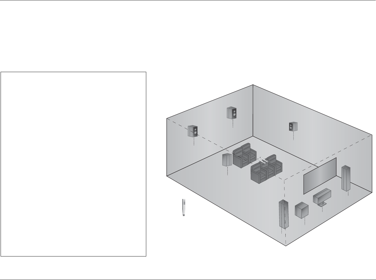
RV-5 Setup
3-37
POSITIONING THE MICROPHONES FOR THE MICROPHONE CHECK
Refer to the microphone placement examples that begin below to position the microphones for the microphone check.
During the microphone check, position
the microphones:
3As close together as possible
3Relatively centered between and equidistant from
the front left and right speakers
3In a clear line-of-sight path with the speakers
3In a location unobstructed by furniture and other
fixtures, where echoes will not obscure calibration
noise signals
3At least 2 feet (0.61m) from all speakers and
walls, but within 30 feet (9.14m) of all speakers
The illustration to the right provides an example of
proper microphone placement during the microphone
check. All of the microphones are positioned as close
together as possible in an unobstructed location that is
equidistant from the front left and right speakers.
PROPER
microphone positioning for the microphone check
Front
Left
Center
Subwoofer
Front
Right
Microphone
Side
Right
Rear
Right
Rear
Left
Side
Left
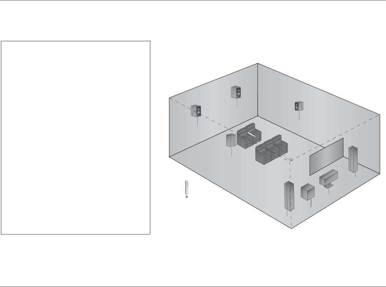
Setup Lexicon
3-38
During the microphone check, DO NOT:
7Separate the microphones
7Scatter the microphones throughout the listening
space
7Obstruct the line-of-sight path between the micro-
phones and the speakers
7Position the microphones on the floor, on seat
cushions, or in locations obstructed by furniture and
other fixtures, where echoes might obscure
calibration noise signals
7Position the microphones within 2 feet (0.61m) of
speakers and walls or more than 30 feet (9.14m)
from any one speaker
The illustration to the right provides an example of
improper microphone placement during the microphone
check. The microphones are scattered throughout the
listening space rather than positioned as close together as
possible in a location that is equidistant from the front left
and right speakers.
IMPROPER
microphone positioning for the microphone check
Front
Left
Center
Subwoofer
Front
Right
Microphone
Side
Right
Rear
Right
Rear
Left
Side
Left
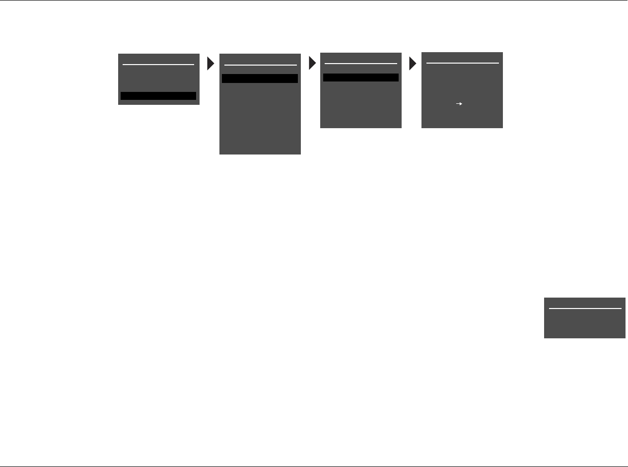
RV-5 Setup
3-39
CHECKING THE MICROPHONES
Note the following:
• The RV-5 outputs calibration noise signals between 55dB and
95dB, beginning with 55dB and increasing in 5dB increments
until the microphones detect the required level. If the
calibration noise signal becomes too loud, press the arrow
button to cancel the microphone check.
• Although the calibration noise signal is output at a fixed volume
level, you should set all volume controls for associated compo-
nents (i.e., speakers, subwoofers and power amplifiers) to a
reasonable level before performing automatic calibration.
When the procedure is finished, the RV-5 automatically reverts
to the last volume level that was selected before automatic
calibration began.
• During automatic calibration, you should refer to the on-screen
display instead of the front-panel display, as additional infor-
mation and instructions are available in the on-screen display.
1. Select the SPEAKER SETUP menu CHECK MICROPHONES option,
as shown above.
2. The first CHECK MICROPHONES screen opens in the on-screen
display, indicating the importance of proper microphone
placement to achieve accurate automatic calibration results.
3. Press the arrow button to begin the microphone check. The
following screens appears in the on-screen display as the micro-
phone check is performed:
CHECKING FOR SILENCE
Appears in the on-screen display while
the RV-5 determines the relative noise
level of the listening space and the
internal noise level of the microphones.
After eliminating microphones that are
not detected or not functioning, the RV-5 calculates an average
level for all microphones.
SPEAKER SETUP
SET CROSSOVERS
CHECK MICROPHONES
AUTOMATIC
MANUAL
CUSTOM SETUP
40 Hz
60 Hz
60 Hz
60 Hz
40 Hz
OFF
N/A
APART
CHECK MICROPHONES
GROUP MICROPHONES
INTO A BUNDLE IN THE
SET CROSSOVERS
BEFORE CALIBRATING
MIDDLE OF THE ROOM
PRESS TO BEGIN
MIC CHECK
MAIN MENU
MODE ADJUST
AUDIO CONTROLS
TUNER PRESETS
SETUP
INPUTS
SPEAKERS
I/O CONFIG
DISPLAYS
VOLUME CONTROLS
TRIGGER
TUNER SETUP
LOCK OPTIONS
LIVE! CALIBRATION
SETUP
POWER MANAGEMENT
CUSTOM SETUP
CHECK MICROPHONES
CHECKING FOR SILENCE
PLEASE WAIT
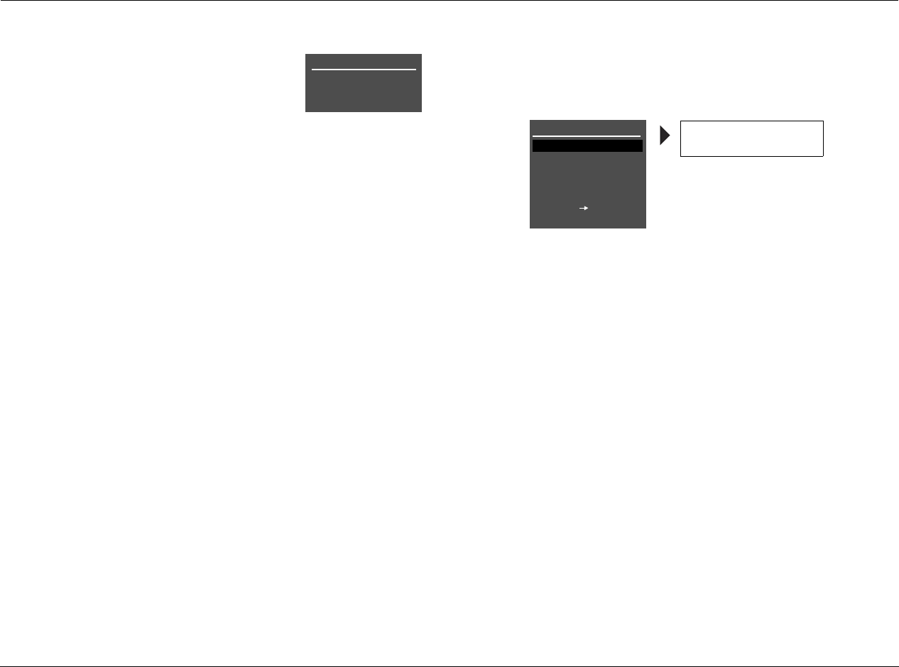
Setup Lexicon
3-40
CHECKING MICROPHONES
Appears in the on-screen display while
the RV-5 confirms the microphone level
calculated during the silence check. To
do this, the RV-5 sends alternating
calibration noise signals to the front left
and right speakers. These signals are output between 55dB and
95dB, beginning with 55dB and increasing in 5dB increments
until the microphones detect the required level. If the signal
becomes too loud, press the arrow button to cancel the
microphone check.
The RV-5 uses the calibration noise signal to eliminate micro-
phones that register the signal at a level that is too low or too
high. Then, the RV-5 determines the appropriate output level for
the calibration noise signal used during automatic calibration.
CHECK MICROPHONES Results
Appears in the on-screen display when the RV-5 is finished
checking the microphones. This display indicates the individual
check results for each microphone.
• An OK result indicates that the microphone passed the
microphone check.
• An ERROR result indicates that the microphone did not pass
the microphone check.
4. Press the and arrow buttons to highlight the desired micro-
phone parameter. The RV-5 refers to the microphones according
to the input connector to which the microphone is connected.
5. Press the arrow button to view more detailed results for the
selected microphone. A message similar to the one shown at the
bottom of the previous column opens in the on-screen display.
Refer to the table on the next page for information about all
possible microphone check messages.
Note the following:
• The RV-5 retains the calculated microphone level until the
SPEAKER SETUP menu is closed. Once this menu is closed,
another microphone check is required before automatic
calibration can be performed.
• Optional microphone kits that include two microphones are
available. Perform automatic calibration with two microphones
that have passed the microphone check.
However, the RV-5 will perform automatic calibration as long as
at least one microphone passes the microphone check. In this
CUSTOM SETUP
CHECK MICROPHONES
CHECKING MICROPHONES
PLEASE WAIT
CHECK MICROPHONES
MIC 1
(MICROPHONE)
OK
MIC 2
PRESS TO VIEW
DETAILS
OK
ERROR

RV-5 Setup
3-41
circumstance, place the successfully checked microphone in the
primary listening position.
• If a microphone check was successful, do not disconnect the
microphones from the microphone input connectors. If the
microphones are disconnected, you should perform the micro-
phone check again before proceeding to automatic calibration.
Setup Lexicon
3-42
CHECKING THE MICROPHONES (continued)
POSITIONING THE MICROPHONES FOR AUTOMATIC CALIBRATION
Proper microphone placement is essential to achieving the desired
automatic calibration results. Microphone placement determines
whether the RV-5 calibrates optimal speaker distances and output
levels for a single listening position, several listening positions in a
single row, or several listening positions in the listening space.
• Refer to the microphone placement examples that begin on the
next page to position the microphones for automatic
calibration. Select the microphone placement that best meets
the needs of the listening space.
Message Description Troubleshooting
The microphone detected the calibration
noise signal without error.
•N/A
The RV-5 did not detect the microphone
during the silence check.
• Examine microphone input connections to ensure that the microphones are properly con-
nected to the RV-5 and that microphone cable plugs are fully inserted for a solid connection.
• The microphone may be damaged. Contact an authorized Lexicon dealer for assistance.
The RV-5 detected the microphone dur-
ing the silence check. However, the
microphone level determined during the
silence check was not confirmed during
the microphone check.
• Examine microphone input connections to ensure that the microphones are properly con-
nected to the RV-5 and that microphone cable plugs are fully inserted for a solid connection.
• The microphones may be positioned too far from the front speakers. Refer to the microphone
placement examples that begin on page 3-37 to confirm that the microphones are appropri-
ately positioned for the microphone check.
• The microphone may be damaged. Contact an authorized Lexicon dealer for assistance.
The microphone level is more than 20dB
below the highest microphone level.
• Examine microphone input connections to ensure that the microphones are properly con-
nected to the RV-5 and that microphone cable plugs are fully inserted for a solid connection.
• The microphones might be positioned too far from the front speakers. Refer to the micro-
phone placement examples that begin on page 3-37 to confirm that the microphones are
appropriately positioned for the microphone check.
• The microphone may be damaged. Contact an authorized Lexicon dealer for assistance.
The microphone level could not be
determined because of excessive room
noise in the listening space.
• Eliminate extraneous noises in the listening space, including conversations, air conditioners
and sounds that filter in through open doors and windows.
• The microphone may be damaged. Contact an authorized Lexicon dealer for assistance.
(MICROPHONE)
OK
(MICROPHONE)
NOT DETECTED
(MICROPHONE)
SIGNAL TOO LOW
(MICROPHONE)
OUT OF RANGE
(MICROPHONE)
TOO MUCH ROOM NOISE
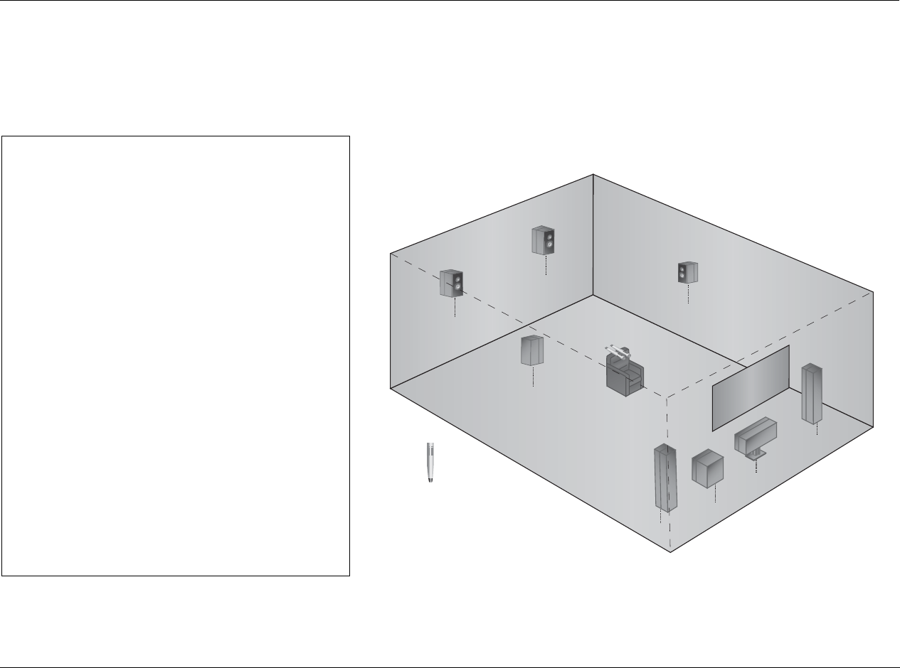
RV-5 Setup
3-43
When calibrating for a single listening
position, place the microphones:
3As close together as possible in a single listening
position (the primary listening position)
3At the approximate spot where the listener’s head
will be during listening
3In a clear line-of-sight path with the speakers
3In a location unobstructed by furniture and other
fixtures, where echoes will not obscure calibration
noise signals
3At least 2 feet (0.61m) from all speakers and
walls, but within 30 feet (9.14m) of all speakers
The illustration to the right provides an example of
proper microphone placement when calibrating for a
single listening position. The microphones are
positioned as close together as possible in a single
listening position, allowing the RV-5 to calibrate optimal
speaker distances and output levels for that position.
PROPER microphone placement to achieve the best results for a single listening position
Front
Left
Center
Subwoofer
Front
Right
Microphone
Side
Right
Rear
Right
Rear
Left
Side
Left
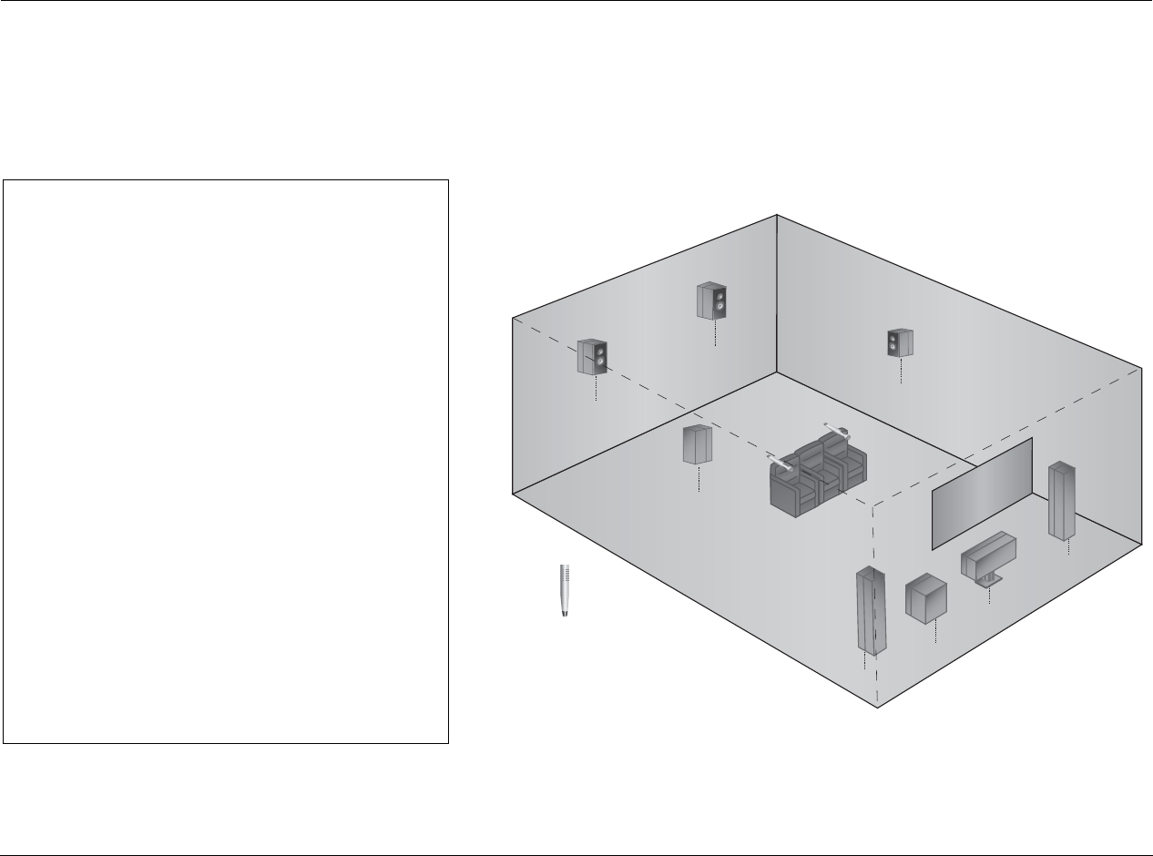
Setup Lexicon
3-44
POSITIONING THE MICROPHONES FOR AUTOMATIC CALIBRATION (continued)
When calibrating for multiple listening
positions in a single row, position the
microphones:
3At the approximate spot where the listener’s head
will be during listening
3In a clear line-of-sight path with the speakers
3In a location unobstructed by furniture and other
fixtures, where echoes will not obscure calibration
noise signals
3At least 2 feet (0.61m) from all speakers and
walls, but within 30 feet (9.14m) of all speakers
The illustration to the right provides an example of
proper microphone placement when calibrating for
multiple listening positions in a single row. Each micro-
phone is positioned in a single listening position within a
single row, allowing the RV-5 to calibrate optimal
speaker distances and output levels for that row at the
expense of a single listening position.
PROPER microphone placement to achieve the best results for multiple listening positions in a single row
Front
Left
Center
Subwoofer
Front
Right
Microphone
Side
Right
Rear
Right
Rear
Left
Side
Left
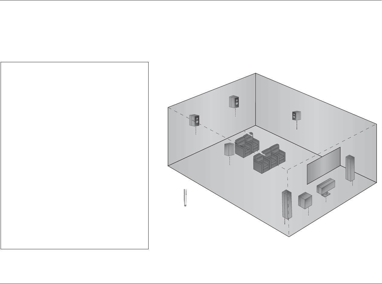
RV-5 Setup
3-45
When calibrating for multiple listening
positions in multiple rows, position the
microphones:
3At the approximate spot where the listener’s head
will be during listening
3In a clear line-of-sight path with the speakers
3In a location unobstructed by furniture and other
fixtures, where echoes will not obscure calibration
noise signals
3At least 2 feet (0.61m) from all speakers and
walls, but within 30 feet (9.14m) of all speakers
The illustration to the right provides an example of
proper microphone placement when calibrating for
multiple listening positions in multiple rows. Each micro-
phone is positioned in a single listening position within a
row, allowing the RV-5 to calibrate optimal speaker
distances and output levels for a larger listening area at
the expense of a single listening position.
PROPER microphone placement to achieve the best results for multiple listening positions in multiple rows
Front
Left
Center
Subwoofer
Front
Right
Microphone
Side
Right
Rear
Right
Rear
Left
Side
Left
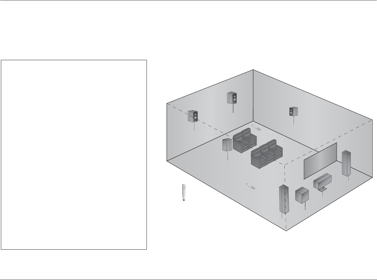
Setup Lexicon
3-46
POSITIONING THE MICROPHONES FOR AUTOMATIC CALIBRATION (continued)
During the automatic calibration, do not:
7Arrange the microphones along the perimeter of
the listening positions or space
7Position the microphones in spots where the
listeners’ heads will not be during listening
7Obstruct the line-of-sight path between the
microphones and the speakers
7Position the microphones on the floor, on seat
cushions, or in locations obstructed by furniture
and other fixtures, where echoes might obscure
calibration noise signals
7Position the microphones within 2 feet (0.61m) of
speakers and walls or more than 30 feet (9.14m)
from any one speaker
The illustration to the right provides an example of
improper microphone placement during the microphone
check. The microphones are positioned on the floor
along the perimeter of the listening space, making it
difficult for the RV-5 to calibrate optimal speaker
distances and output levels for the actual listening
positions.
IMPROPER microphone positioning for automatic calibration
Front
Left
Center
Subwoofer
Front
Right
Microphone
Side
Right
Rear
Right
Rear
Left
Side
Left
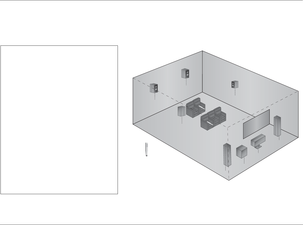
RV-5 Setup
3-47
During the automatic calibration, do not:
7Arrange the microphones along the perimeter of
the listening positions or space
7Position the microphones at spots where the
listeners’ heads will not be during listening
7Obstruct the line-of-sight path between the
microphones and the speakers
7Position the microphones on the floor, on seat
cushions, or in locations obstructed by furniture
and other fixtures, where echoes might obscure
calibration noise signals
7Position the microphones within 2 feet (0.61m) of
speakers and walls or more than 30 feet (9.14m)
from any one speaker
The illustration to the right provides an example of
improper microphone placement during the microphone
check. The microphones are positioned on seat cushions
rather than in spots where the listener’s heads will be
during listening.
IMPROPER microphone positioning for automatic calibration
Front
Left
Center
Subwoofer
Front
Right
Microphone
Side
Right
Rear
Right
Rear
Left
Side
Left
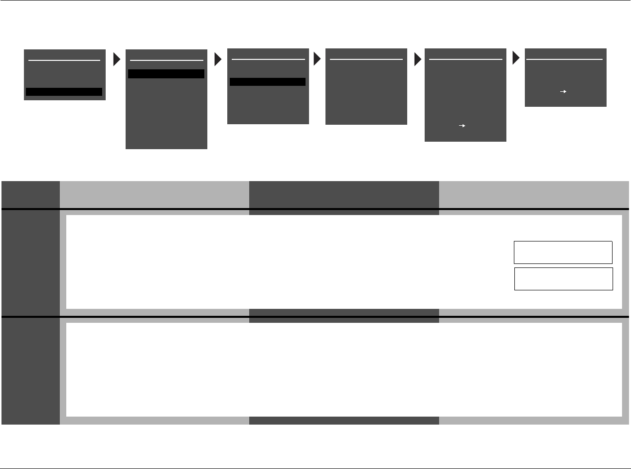
Setup Lexicon
3-48
PERFORMING AUTOMATIC CALIBRATION
STEP DISTANCES DISTANCES & LEVELS LEVELS
1
2
AUTO SPEAKER SETUPSPEAKER SETUP
SET CROSSOVERS
CHECK MICROPHONES
AUTOMATIC
MANUAL
CUSTOM SETUP
40 Hz
60 Hz
60 Hz
60 Hz
40 Hz
OFF
N/A
APART
AUTO SPEAKER SETUP
DISTANCES & LEVELS
SET CROSSOVERS
BEFORE CALIBRATING
DISTANCES
OUTPUT LEVELS
PLACE MICROPHONES
AROUND PREFERRED
LISTENING POSITIONS
CUSTOM SETUP
40 Hz
60 Hz
60 Hz
60 Hz
40 Hz
OFF
N/A
APART
AUTO SPEAKER SETUP
!CAUTION!
HIGH AUDIO LEVELS
TEST WILL BEGIN IN
10
YOU WILL HAVE 10 SEC
TO LEAVE THE ROOM OR
SIT QUIETLY
PRESS TO BEGIN
COUNTDOWN
PRESS TO SKIP
COUNTDOWN
Follow the procedures in the appropriate table column for the desired type of automatic calibration.
MAIN MENU
MODE ADJUST
AUDIO CONTROLS
TUNER PRESETS
SETUP
INPUTS
SPEAKERS
I/O CONFIG
DISPLAYS
VOLUME CONTROLS
TRIGGER
TUNER SETUP
LOCK OPTIONS
LIVE! CALIBRATION
SETUP
POWER MANAGEMENT
Select the SPEAKER SETUP menu AUTOMATIC option, as shown in the menu illustration above.
• If a microphone check is successful, the AUTO SPEAKER SETUP menu appears in the on-screen display. Press
the or arrow button to highlight the automatic calibration option you want. Then press the arrow button to select
this option. Refer to the table on page 3-35 for more information about automatic calibration options.
• If a microphone check is unsuccessful, one of the error messages shown to the right appears in the on-screen display, indicat-
ing that a successful microphone check is required before automatic calibration, and also the reason the previous check failed.
If this occurs, go back to “Connecting the Microphones” on page 3-36 and work your way back to this page.
MIC CHECK REQUIRED
FOR AUTO CALIBRATION
NO MICROPHONE
DETECTED
The following AUTO SPEAKER SETUP messages are displayed before automatic calibration begins:
• The !CAUTION! HIGH AUDIO LEVELS message indicates that the RV-5 generates loud calibration noise signals during automatic calibration. If the sig-
nals become too loud, press the arrow button to cancel automatic calibration. Press the arrow button to open the next AUTO SPEAKER SETUP
menu.
• The countdown display notifies you that automatic calibration will begin in 10 seconds. The primary reason for the 10 second delay is to give you time
to leave the listening space before automatic calibration begins. If you choose to remain in the room, your movements could affect the calibration
results. If you leave the room, you can return in about 10 minutes (the calibration procedure should be completed). Press the arrow button to
skip the countdown and begin automatic calibration. The RV-5 automatically activates automatic calibration when the countdown ends.
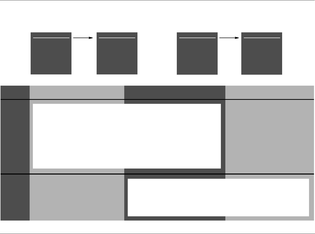
RV-5 Setup
3-49
STEP DISTANCES DISTANCES & LEVELS LEVELS
3
This step does not occur when the AUTO
SPEAKER SETUP menu LEVELS option is
selected.
4
This step does not occur when the AUTO SPEAKER
SETUP menu DISTANCES option is selected.
CUSTOM SETUP
SETTING DISTANCES
FRONT LEFT
CENTER
FRONT RIGHT
SIDE RIGHT
REAR RIGHT
REAR LEFT
SIDE LEFT
SUBWOOFER
0.0ft
0.0ft
0.0ft
0.0ft
0.0ft
0.0ft
0.0ft
0.0ft
CUSTOM SETUP
SETTING DISTANCES
FRONT LEFT
CENTER
FRONT RIGHT
SIDE RIGHT
REAR RIGHT
REAR LEFT
SIDE LEFT
SUBWOOFER
12.0ft
10.5ft
12.0ft
4.5ft
ERROR
6.0ft
4.5ft
N/A
CUSTOM SETUP
SETTING LEVELS
FRONT LEFT
CENTER
FRONT RIGHT
SIDE RIGHT
REAR RIGHT
REAR LEFT
SIDE LEFT
SUBWOOFER
0.0dB
0.0dB
0.0dB
0.0dB
0.0dB
0.0dB
0.0dB
0.0dB
CUSTOM SETUP
SETTING LEVELS
FRONT LEFT
CENTER
FRONT RIGHT
SIDE RIGHT
REAR RIGHT
REAR LEFT
SIDE LEFT
SUBWOOFER
-2.0dB
ERROR
-2.0dB
-4.5dB
-3.0dB
-3.0dB
-4.5dB
N/A
The SETTING DISTANCES menu is displayed when the RV-5 calibrates speaker distances.
• During speaker distance calibration, the RV-5 sends calibration noise signals to the Main Zone
audio output connectors in the order shown on the SETTING DISTANCES menu. The cursor auto-
matically scrolls downward through speaker calibration parameters, highlighting each parameter
while the RV-5 calculates a distance for the corresponding speaker. As it finishes each parameter,
the RV-5 enters the calibrated value or an ERROR message to the right of the parameter label.
• Because of the way low-frequency signals propagate in most listening spaces, automatic speaker dis-
tance calibration often produces unreliable results for subwoofers. For this reason, the RV-5 does not
send calibration noise signals to the Subwoofer connector during speaker distance calibration. Instead,
the RV-5 automatically calibrates the subwoofer distance to the shortest distance of the other speakers.
These distances can be manually adjusted. See “PERFORMING MANUAL SPEAKER DISTANCE CALIBRA-
TION” on page 3-54.
The SETTING LEVELS menu is displayed when the RV-5 calibrates output levels.
• During speaker levels calibration, the RV-5 sends calibration noise signals to the Main Zone
audio output connectors in the order shown on the SETTING LEVELS menu. The cursor auto-
matically scrolls downward through speaker calibration parameters, highlighting each parame-
ter while the RV-5 calculates an output level for the corresponding speaker. As it finishes each
parameter, the RV-5 enters the calibrated value or an ERROR message to the right of the param-
eter label.
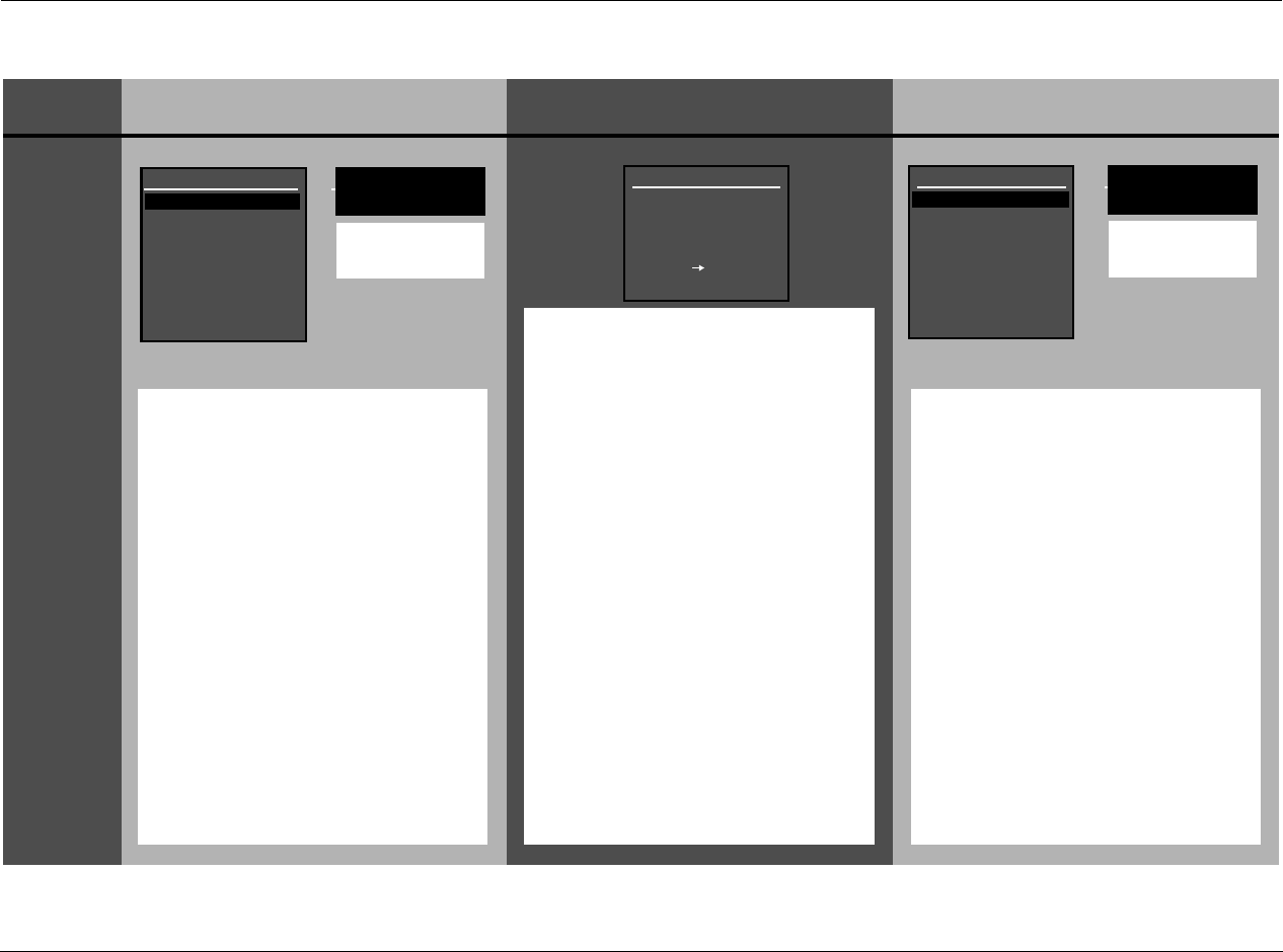
Setup Lexicon
3-50
PERFORMING AUTOMATIC CALIBRATION (continued)
STEP DISTANCES DISTANCES & LEVELS LEVELS
5
FRONT LEFT
Refer to the table on page
3-52 for information about
all possible speaker calibra-
tion messages.
FRONT LEFT
Refer to the table on page
3-52 for information about
all possible speaker calibra-
tion messages.
If there was a DISTANCES calibration
error, an AUTO DISTANCES menu auto-
matically displays.
• A value indicates that no errors occurred
during the calibration procedure.
• An ERROR message indicates that a value
was calculated, but at least one error
occurred during the calibration proce-
dure.
• Press the or arrow button to high-
light the speaker calibration parameter
you want. Then press the button to
view more detailed results for the
selected speaker. A message similar to
the one shown above will display.
• Refer to the table on page 3-52 for infor-
mation about all possible speaker calibra-
tion messages.
• This menu is displayed, but not user
accessible during Auto Distance Calibra-
tion or after Auto Calibration.
When the RV-5 is finished calibrating
speaker distances and output levels, if there
was a calibration error, the AUTO SPEAKER
SETUP screen is displayed, indicating the
results for each calibration procedure.
• An OK message indicates that no errors
occurred during the calibration proce-
dure.
• An ERROR message indicates that values
were calculated, but at least one error
occurred during calibration.
• Press the or arrow button to high-
light the desired calibration procedure.
DISTANCES displays the AUTO DIS-
TANCES screen shown in the left column
of this table.
LEVELS displays the AUTO LEVELS screen
shown in the right column of this table.
• Press the arrow button to select this
procedure.
• Refer to the instructions in the appropri-
ate column to view more detailed results
for each individual speaker.
• If a speaker is highlighted in either the
Distances or Levels menus, the speaker
name is displayed.
If there was a LEVELS calibration error, an
AUTO LEVELS menu automatically dis-
plays.
• A value indicates that no errors occurred
during the calibration procedure.
• An ERROR message indicates that a value
was calculated, but at least one error
occurred during the calibration proce-
dure.
•Press theor arrow button to high-
light the desired speaker calibration
parameter. Then, press the arrow
button to view more detailed results for
the selected speaker. A message similar
to the one shown above will display.
• Refer to the table on page 3-52 for infor-
mation about all possible speaker calibra-
tion messages.
• This menu is displayed, but not user
accessible during Auto Distance Calibra-
tion or after Auto Calibration.
AUTO SPEAKER SETUP
DISTANCES
LEVELS
AUTO VALUES APPLIED
PRESS TO VIEW
DETAILS
OK
ERROR
AUTO LEVELS
FRONT LEFT
CENTER
FRONT RIGHT
SIDE RIGHT
REAR RIGHT
REAR LEFT
SIDE LEFT
SUBWOOFER
-2.0dB
ERROR
-2.0dB
-4.5dB
-3.0dB
-3.0dB
-4.5dB
N/A
AUTO DISTANCES
FRONT LEFT
CENTER
FRONT RIGHT
SIDE RIGHT
REAR RIGHT
REAR LEFT
SIDE LEFT
SUBWOOFER
12.0ft
10.5ft
12.0ft
4.5ft
ERROR
6.0ft
4.5ft
N/A
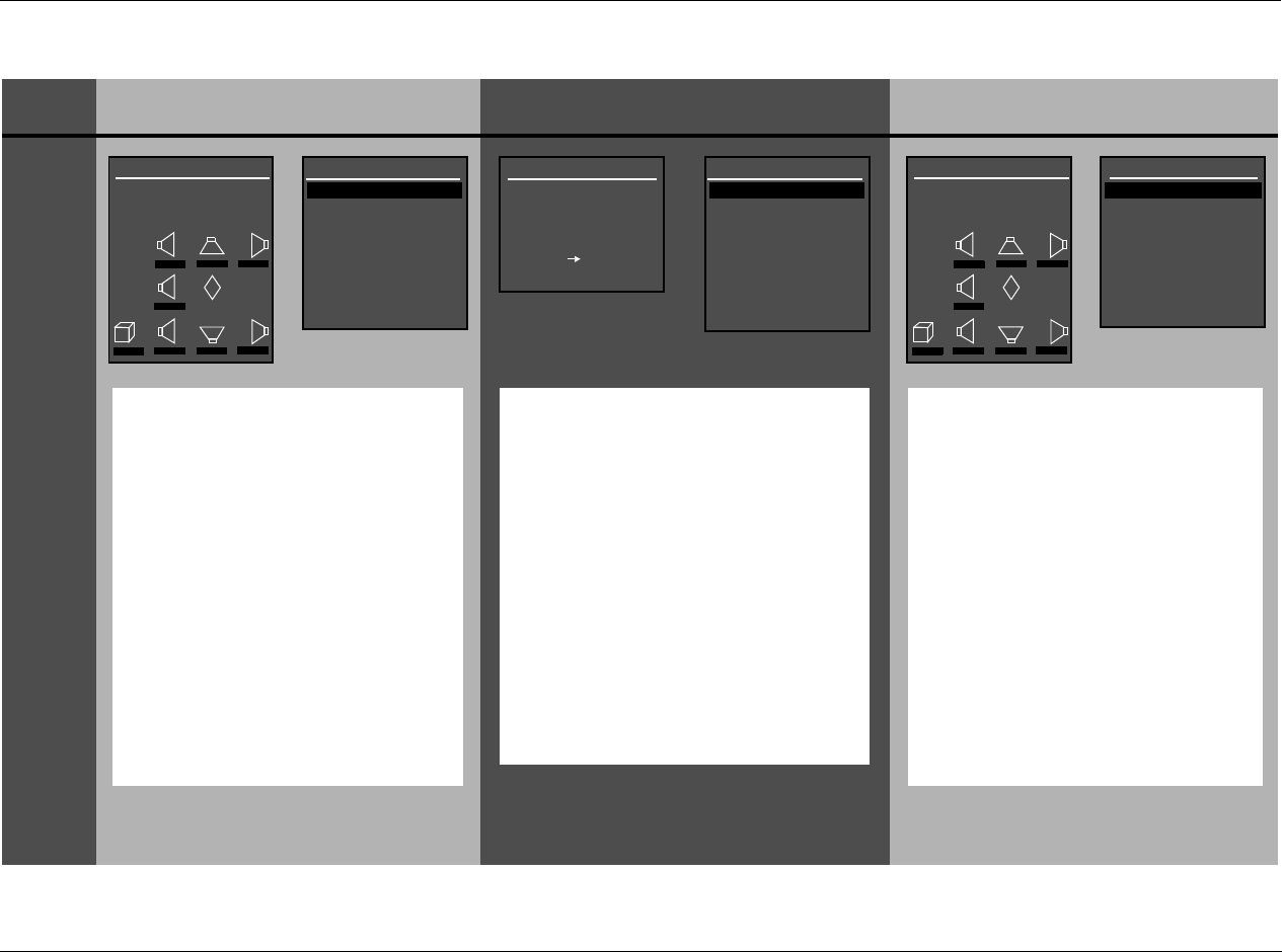
RV-5 Setup
3-51
STEP DISTANCES DISTANCES & LEVELS LEVELS
6
AUTO DISTANCES*
FRONT LEFT
CENTER
FRONT RIGHT
SIDE RIGHT
REAR RIGHT
REAR LEFT
SIDE LEFT
SUBWOOFER
12.0ft
10.5ft
12.0ft
4.5ft
ERROR
6.0ft
4.5ft
N/A
SET DISTANCES
Use the SET DISTANCES menu to select
the desired speaker distances.
1 Press the arrow button to return to
the SET DISTANCES menu.
2 Press the or arrow button to tog-
gle between calibrated speaker distances
(AUTO) and original speaker distances.
The speaker graphics at the bottom of
the menu update to indicate the selected
values.
3 Press the button to apply the
selected values. A confirmation message
is displayed to indicate the applied val-
ues.
4 Press the button twice in succession
to return to the SPEAKER SETUP menu.
The AUTO DISTANCES menu is only accessi-
ble after the DISTANCES & LEVELS calibra-
tion is performed as a combined procedure.
Use the AUTO SPEAKER SETUP menu to
select speaker distances or levels.
1 Press the arrow button to return to the
AUTO SPEAKER SETUP results screen.
2 To select the other calibration procedure,
follow the instructions in Step 5. Otherwise,
press the button to return to the
SPEAKER SETUP menu.
*Note: The AUTO DISTANCES screen is shown
above as an example. The AUTO LEVELS
screen can be substituted.
Use the SET LEVELS menu to select the
desired speaker levels.
1 Press the arrow button to return to
the SET LEVELS menu.
•Press theand arrow buttons to
toggle between calibrated output levels
(AUTO) and original output levels. The
speaker graphics at the bottom of the
menu update to indicate the selected
values.
•Press the
arrow button to apply the
selected values. A confirmation message is
displayed to indicate the applied values.
• Press the arrow button twice in suc-
cession to return to the SPEAKER SETUP
menu.
The AUTO LEVELS menu is only accessible
after the DISTANCES & LEVELS calibration is
performed as a combined procedure.
AUTO SPEAKER SETUP
DISTANCES
LEVELS
AUTO VALUES APPLIED
PRESS TO VIEW
DETAILS
OK
ERROR
AUTO LEVELS
FRONT LEFT
CENTER
FRONT RIGHT
SIDE RIGHT
REAR RIGHT
REAR LEFT
SIDE LEFT
SUBWOOFER
-2.0dB
ERROR
-2.0dB
-4.5dB
-3.0dB
-3.0dB
-4.5dB
N/A
AUTO DISTANCES
FRONT LEFT
CENTER
FRONT RIGHT
SIDE RIGHT
REAR RIGHT
REAR LEFT
SIDE LEFT
SUBWOOFER
12.0ft
10.5ft
12.0ft
4.5ft
ERROR
6.0ft
4.5ft
N/A
AUTO DISTANCES
ORIGINAL DISTANCES
C
R SR RR
L SL RL
M
SUB
0.0ft 0.0ft 0.0ft
0.0ft
0.0ft 0.0ft 0.0ft 0.0ft
SET LEVELS
AUTO LEVELS
ORIGINAL LEVELS
C
R SR RR
L SL RL
M
SUB
0.0dB 0.0dB 0.0dB
0.0dB
0.0dB 0.0dB 0.0dB 0.0dB
Setup Lexicon
3-52
PERFORMING AUTOMATIC CALIBRATION (continued)
Message Description Troubleshooting
The RV-5 successfully calibrated the value
for the selected speaker without error.
•N/A
The selected speaker is not present in the
speaker setup.
• Set the corresponding CUSTOM or THX SETUP menu parameter to include the selected
speaker in the speaker setup. (The RV-5 only calibrates values for speakers that are included in
the speaker setup.)
The microphones detected out-of-phase
calibration noise signals, but the cali-
brated value is still accurate.
• Examine speaker/associated amplifier connections to ensure that speaker wires are not crossed.
• Dipolar speakers could cause this error. However, the RV-5 does not report this error unless at
least half of the microphones detect out-of-phase calibration noise signals.
• Reflections from room objects could cause this error.
• Drivers intentionally wired out-of-phase could cause this error.
The microphones detected calibration
noise signals at an unusually low level.
• The microphones might be positioned more than 30 feet (9.14m) from the selected speaker or in a
location where echoes obscure calibration noise signals. Refer to the placement examples on pages
3-40 to 3-44 to confirm that the microphones are appropriately positioned for automatic calibration.
• Examine microphone input connections to ensure that the microphones are properly con-
nected to the RV-5 and that microphone cable plugs are fully inserted for a solid connection.
The microphones did not detect calibra-
tion noise signals or the RV-5 could not
calculate a value.
• Refer to the microphone placement examples on pages 3-41 to 3-45 to confirm that the
microphones are appropriately positioned for automatic calibration.
• Examine microphone input connections to ensure that the microphones are properly con-
nected to the RV-5 and that microphone cable plugs are fully inserted for a solid connection.
One or more microphones did not detect
calibration noise signals at a reasonable
level. The calibrated value could be inac-
curate.
• Refer to the microphone placement examples on pages 3-41 to 3-45 to confirm that the
microphones are appropriately positioned for automatic calibration.
The microphones detected calibration
noise signals at an unusually high level.
• Decrease associated amplifier volume levels – including (if applicable) powered subwoofer amplifiers.
• The microphones may be positioned too close (within 2 feet [0.61m]) of the selected speaker.
Refer to the microphone placement examples on pages 3-41 to 3-45 to confirm that the micro-
phones are appropriately positioned for automatic calibration.
The microphones detected calibration
noise signals at an unusually low level.
• Increase associated amplifier volume levels – including (if applicable) powered subwoofer amplifiers.
• The microphones may be positioned too far away (more than 30 feet [9.14m]) from the
selected speaker. See the microphone placement examples on pages 3-41 to 3-45 to confirm
that the microphones are appropriately positioned for automatic calibration.
(SPEAKER)
OK
(SPEAKER)
SPEAKER IS NOT ENABLED
(SPEAKER)
SPEAKER OUT OF PHASE
(SPEAKER)
SIGNAL TOO LOW
(SPEAKER)
UNABLE TO CALCULATE
(SPEAKER)
MAY NOT BE ACCURATE
(SPEAKER)
SPKR OUTPUT TOO HIGH
(SPEAKER)
SPKR OUTPUT TOO LOW
RV-5 Setup
3-53
MANUAL CALIBRATION
Selecting the SPEAKER SETUP menu MANUAL option displays the MANUAL SPEAKER SETUP menu, to manually calibrate speaker distances and
output levels. The table below indicates available manual calibration options.
Manual Options Details
SPEAKER DISTANCES • Provides manual calibration and individual adjustment of speaker distances.
INTERNAL NOISE TEST • Provides manual calibration and individual adjustment of output levels.
• Automatically sends an internal calibration noise signal to each Main Zone audio output connector,
allowing for simultaneous output level adjustment.
EXTERNAL NOISE TEST • Provides manual calibration and individual adjustment of output levels.
• Requires an external calibration source such as an audio calibration disc.
• Activates an appropriate listening mode based on the current Main Zone input source.
BASS PEAK LIMITERS • Provides amplitude limits for low-frequency signals sent to the Main Zone audio output connector
labeled Subwoofer, and low-frequency signals redirected to other Main Zone audio output connectors.
• Protects speakers against input sources that produce low-frequency signal peaks.
SPEAKERSSETUP MANUAL
SPEAKER SETUP
SET CROSSOVERS
CHECK MICROPHONES
AUTOMATIC
MANUAL
CUSTOM SETUP
40 Hz
60 Hz
60 Hz
60 Hz
40 Hz
OFF
N/A
APART
MANUAL SPEAKER SETUP
SPEAKER DISTANCES
LEVELS CALIBRATION
C
R SR RR
L SL RL
M
SUB
0.0dB 0.0dB 0.0dB
0.0dB
0.0dB 0.0dB 0.0dB 0.0dB
SET CROSSOVERS
BEFORE CALIBRATING
MAIN MENU
MODE ADJUST
AUDIO CONTROLS
TUNER PRESETS
SETUP
INPUTS
SPEAKERS
I/O CONFIG
DISPLAYS
VOLUME CONTROLS
TRIGGER
TUNER SETUP
LOCK OPTIONS
LIVE! CALIBRATION
SETUP
POWER MANAGEMENT
Setup Lexicon
3-54
PERFORMING MANUAL SPEAKER DISTANCE CALIBRATION
Selecting the MANUAL SPEAKER SETUP menu SPEAKER DISTANCES option displays the SPEAKER DISTANCES menu, to manually calibrate speaker
distances.
To manually calibrate speaker distances:
1. Follow the menu path shown above to select MANUAL SPEAKER
SETUP SPEAKER DISTANCES. The SPEAKER DISTANCES menu
shown above will open in the on-screen display.
2. Press the or arrow buttons to highlight the desired speaker
distance parameter. Then, press the arrow button to select the
highlighted speaker distance parameter.
3. To determine the appropriate speaker distance, measure the
distance between the primary listening position and the front of
the speaker.
For example, when the FRONT LEFT parameter is selected,
measure the distance between the primary listening position
and the front of the front left speaker (connected to the Main
Zone audio output connector labeled Front L).
4. When the speaker distance has been measured, press the
and arrow buttons to set the parameter to the closest available
value.
SPEAKERSSETUP MANUAL SPEAKER DISTANCES
MANUAL SPEAKER SETUPSPEAKER SETUP
SET CROSSOVERS
CHECK MICROPHONES
AUTOMATIC
MANUAL
SPEAKER DISTANCES
LEVELS CALIBRATION
C
R SR RR
L SL RL
M
SUB
0.0ft 0.0ft 0.0ft
0.0ft
0.0ft 0.0ft 0.0ft 0.0ft
SET CROSSOVERS
BEFORE CALIBRATING
CUSTOM SETUP
SPEAKER DISTANCES
FRONT LEFT
CENTER
FRONT RIGHT
SIDE RIGHT
REAR RIGHT
REAR LEFT
SIDE LEFT
SUBWOOFER
UNITS
0.0ft
0.0ft
0.0ft
0.0ft
0.0ft
0.0ft
0.0ft
0.0ft
FEET
METERS
FEET
0.0 to 30.0ft or 12.0m
MAIN MENU
MODE ADJUST
AUDIO CONTROLS
TUNER PRESETS
SETUP
INPUTS
SPEAKERS
I/O CONFIG
DISPLAYS
VOLUME CONTROLS
TRIGGER
TUNER SETUP
LOCK OPTIONS
LIVE! CALIBRATION
SETUP
POWER MANAGEMENT
RV-5 Setup
3-55
PERFORMING MANUAL OUTPUT LEVEL CALIBRATION
Selecting the MANUAL SPEAKER SETUP menu LEVELS CALIBRATION option displays the LEVELS CALIBRATION menu shown below, to manually
calibrate output levels.
Note the following:
• Use a Sound Pressure Level (SPL) meter to manually calibrate
output levels. A SPL meter is a device that measures the relative
loudness of the speakers to ensure accurate output level
calibration. SPL meters are available from electronic retailers
such as Radio Shack.
• Output levels should be calibrated from the primary listening
position, placing the SPL meter at the approximate location
where the listener’s head will be during listening.
• Output levels for speakers that are not included in the speaker
setup cannot be adjusted during the internal noise test. These
output levels can be adjusted during the external noise test, but
there is no need to do so.
SPEAKERSSETUP MANUAL LEVELS CALIBRATION
MAIN MENU
MODE ADJUST
AUDIO CONTROLS
TUNER PRESETS
SETUP
INPUTS
SPEAKERS
I/O CONFIG
DISPLAYS
VOLUME CONTROLS
TRIGGER
TUNER SETUP
LOCK OPTIONS
LIVE! CALIBRATION
SETUP
INTERNAL NOISE
MANUAL SPEAKER SETUPSPEAKER SETUP
SET CROSSOVERS
CHECK MICROPHONES
AUTOMATIC
MANUAL
SPEAKER DISTANCES
LEVELS CALIBRATION
C
R SR RR
L SL RL
M
SUB
0.0dB 0.0dB 0.0dB
0.0dB
0.0dB 0.0dB 0.0dB 0.0dB
SET CROSSOVERS
BEFORE CALIBRATING
CUSTOM SETUP
LEVELS CALIBRATION
INTERNAL NOISE TEST
CUSTOM SETUP
SPEAKER LEVEL ADJUST
FRONT LEFT
CENTER
FRONT RIGHT
SIDE RIGHT
REAR RIGHT
REAR LEFT
SIDE LEFT
SUBWOOFER
+0.0dB
+0.0dB
+0.0dB
+0.0dB
+0.0dB
+0.0dB
+0.0dB
+0.0dB
-18.0 to +12.0dB
EXTERNAL NOISE TEST
BASS PEAK LIMITERS
!CAUTION!
HIGH AUDIO LEVELS
POWER MANAGEMENT

Setup Lexicon
3-56
INTERNAL NOISE TEST
Opens the INTERNAL NOISE message shown on the previous page,
which indicates that the internal noise test generates loud calibration
noise signals.
When the INTERNAL NOISE message opens:
•Press thearrow button to open the SPEAKER LEVEL ADJUST
menu shown on the previous page. When the SPEAKER LEVEL
ADJUST menu opens, the internal noise test automatically
begins.
•Press thebutton to skip the internal noise test.
During the internal noise test, the RV-5 sends calibration noise signals
to each speaker in the order shown on the SPEAKER LEVEL ADJUST
menu. The cursor automatically scrolls through output level param-
eters, highlighting each parameter as the RV-5 sends the calibration
noise signal to the corresponding speaker. The calibration noise
signal is sent to each speaker for about 4 seconds.
Note:
When the internal noise test begins, the RV-5 automatically sets
volume level to +0dB. Avoid adjusting the master volume level while
the test is in progress, to achieve THX reference levels (75dB).
INTERNAL NOISE TEST LEVELS CALIBRATION MANUAL SPEAKERS SETUP
To manually calibrate output levels during the internal noise test:
1. Set the SPL meter to “C” weighting and “SLOW” response.
2. Place the SPL meter at the primary listening position.
3. Press the or arrow button to highlight the desired output
level parameter. Then, quickly press the button to select this
output level parameter. The horizontal bar graph shown on the
previous page will open in the on-screen display and automatic
scrolling will stop.
Note:
During the internal noise test, it is possible to select an output level
parameter just as the cursor is about to automatically scroll to the
next parameter, causing the RV-5 to send the calibration noise
signal to both speakers. If this occurs, reselect the desired speaker.
4. When the horizontal bar graph opens, press the or button
to select the output level that achieves a 75dB SPL meter reading
from the primary listening position.
5. Press to close the parameter. The internal noise test will
continue and automatic scrolling will resume.
6. Repeat steps 2, 3, 4 and 5 until all desired output levels have
been set.
SPEAKERSSETUP MANUAL LEVELS CALIBRATION INTERNAL NOISE TEST
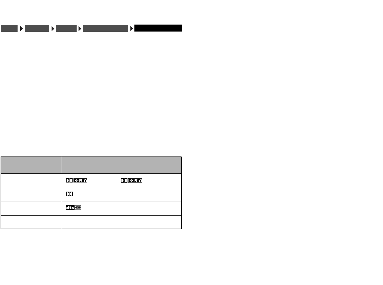
RV-5 Setup
3-57
EXTERNAL NOISE TEST
Selecting the LEVELS CALIBRATION menu EXTERNAL NOISE TEST
option opens the SPEAKER LEVEL ADJUST menu shown on page 3-55,
which manually calibrates output levels.
The external noise test requires an external calibration source such as
an audio calibration disc. When the external noise test is conducted,
the RV-5 activates a listening mode based on the current Main Zone
input source. Refer to the table below for more information about
external noise test listening mode activation.
When a listening mode is activated during the external noise test, all
custom listening mode menu parameter settings are ignored. The
listening mode is applied to the current Main Zone input source in its
factory-default condition. When the external noise test is finished, the
listening mode returns to its custom condition.
EXTERNAL NOISE TEST LEVELS CALIBRATION MANUAL SPEAKERS SETUP
* These listening modes depend on the speaker configuration. Dolby Pro Logic IIx MOVIE
will only load when side and rear speakers are present.
**These listening mode names differ depending on the current input source, speaker
setup and parameter settings. Refer to the Listening Mode Descriptions section
beginning on page 6-4 for more information.
**If the Advanced Menu input is set to “ANALOG BYPASS OFF” the listening mode for the
EXTERNAL NOISE TEST is “5.1a STANDARD”.
Note:
When the external noise test begins, the RV-5 automatically sets
volume level to +0dB. Avoid adjusting the master volume level while
the test is in progress, to achieve THX reference levels (75dB).
To manually calibrate output levels during the external noise test:
1. Set the SPL meter to “C” weighting and “SLOW” response.
2. Place the SPL meter at the primary listening position.
3. Press the or arrow button to highlight the output level
parameter you want. Then press the button to select this
output level parameter.
The horizontal bar graph shown on page 3-55 is displayed.
4. Begin playback of the external calibration source and press the
or arrow button to select the output level that achieves a 75dB
SPL Meter reading.
5. After selecting the output level, press the arrow button to close
the horizontal bar graph.
6. Repeat steps 3, 4 and 5 until you have set all the output levels you
want.
SPEAKERSSETUP MANUAL LEVELS CALIBRATION EXTERNAL NOISE TEST
INPUT SOURCE LISTENING MODE
2-Channel PLII MOVIE, PLIIx MOVIE*
Dolby Digital DIGITAL**
DTS(-ES) *
5.1-Channel Analog 5.1a BYPASS***
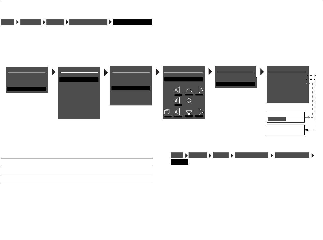
Setup Lexicon
3-58
SETTING BASS PEAK LIMITERS
The BASS PEAK LIMITERS option displays the BASS PEAK LIMITERS menu, to set amplitude limits on low-frequency signals sent to the Main Zone
audio output connectors, including the Subwoofer. The RV-5 is equipped with an internal limiter to prevent low-frequency signals from exceeding
a designated output level. This is essential for Dolby Digital and DTS(-ES) sources that produce low-frequency signal peaks at much higher output
levels than 2-channel sources. In home theaters, there is a danger of the subwoofers and their associated amplifiers overloading when attempting
to reproduce low-frequency signals.
Note:
Configure BASS PEAK LIMITERS menu parameter settings whether
output levels are automatically or manually calibrated.
CAL NOISE ON, OFF
Determines whether bass peak limiters are set with an internal or
external calibration source.
To set the CAL NOISE parameter:
• Select ON to activate an internal calibration noise signal to set
bass peak limiters.
• Select OFF to deactivate the internal calibration noise signal.
Setting bass peak limiters with the calibration noise set to OFF requires
an external calibration source such as an audio calibration disc.
SPEAKERSSETUP MANUAL LEVELS CALIBRATION BASS PEAK LIMITERS
MAIN MENU
MODE ADJUST
AUDIO CONTROLS
TUNER PRESETS
SETUP
INPUTS
SPEAKERS
I/O CONFIG
DISPLAYS
VOLUME CONTROLS
TRIGGER
TUNER SETUP
LOCK OPTIONS
LIVE! CALIBRATION
SETUP
SPEAKER SETUP
SET CROSSOVERS
CHECK MICROPHONES
AUTOMATIC
MANUAL
MANUAL SPEAKER SETUP
SPEAKER DISTANCES
LEVELS CALIBRATION
C
R SR RR
L SL RL
M
SUB
0.0dB 0.0dB 0.0dB
0.0dB
0.0dB 0.0dB 0.0dB 0.0dB
SET CROSSOVERS
BEFORE CALIBRATING
LEVELS CALIBRATION
INTERNAL NOISE TEST
EXTERNAL NOISE TEST
BASS PEAK LIMITERS
BASS PEAK LIMITER
CAL NOISE
LIMITER
LIMIT ADJ
!CAUTION!
HIGH AUDIO LEVELS
ON
ON
100dB
ON
OFF
75 to 120dB
POWER MANAGEMENT
Parameter Default Setting Possible Setting
CAL NOISE ON ON, OFF
LIMITER ON ON, OFF
LIMIT ADJ 100dB 75 to 120dB
SPEAKERSSETUP MANUAL LEVELS CALIBRATION BASS PEAK LIMITERS
CAL NOISE
RV-5 Setup
3-59
LIMITER ON, OFF
Limits low-frequency signals sent to the subwoofer or redirected to
other speakers.
To set the LIMITER parameter:
•Select ON to restrict the output level of the low-frequency
signals to the LIMIT ADJ parameter setting.
•Select OFF to allow an unrestricted signal output level,
regardless of the LIMIT ADJ parameter setting.
LIMIT ADJ 75 to 120dB
Sets amplitude limits applied to the Subwoofer output connector,
and to other Main Zone audio output connectors to which low-
frequency signals are redirected.
To set the LIMIT ADJ parameter:
1. Select the LIMIT ADJ parameter.
The parameter initially sets to 75dB.
2. Press the and arrow buttons to change the parameter value.
The selected amplitude is applied when the SUB LIMITER
parameter is set to ON.
SPEAKERSSETUP MANUAL LEVELS CALIBRATION BASS PEAK LIMITERS
LIMITER
SPEAKERSSETUP MANUAL LEVELS CALIBRATION BASS PEAK LIMITERS
LIMITER ADJ
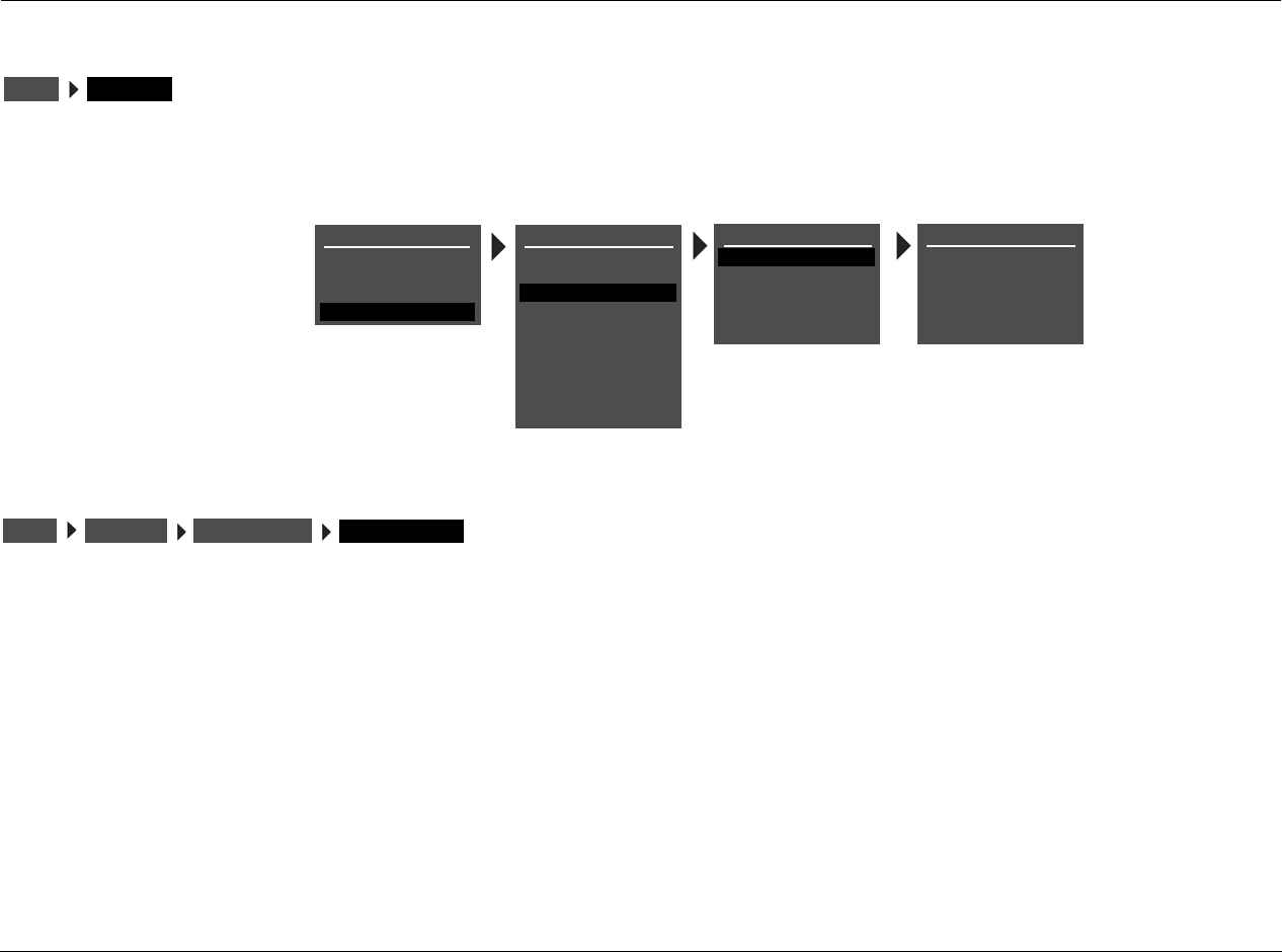
Setup Lexicon
3-60
I/O CONFIG
The I/O CONFIG option is used to configure the analog audio input connectors as eight (Left/Right) stereo connectors, five (Left/Right) stereo
connectors and one 5.1-channel configuration (Front L/R, Center, Subwoofer, Side L/R), or as two stereo connectors and two 5.1-channel
configurations.
8 STEREO INPUTS
Select the 8 STEREO INPUTS option to configure the analog audio
input connectors as eight stereo connectors.
When 8 STEREO INPUTS is selected:
• All analog audio input connectors are configured as stereo
connectors.
• The 5.1-channel connectors are not available.
• Input sources that were assigned to the 5.1 ANLG (3-5) and 5.1
ANLG (6-8) are reassigned to the stereo connectors labeled 3
and 6, respectively.
I/O CONFIGSETUP
REAR PANEL CONFIG
8 STEREO INPUTS
OR
5 ST. & (1) 5.1 ANLG
OR
2 ST. & (2) 5.1 ANLG
SETUP
INPUTS
SPEAKERS
I/O CONFIG
DISPLAYS
VOLUME CONTROLS
TRIGGER
TUNER SETUP
MAIN MENU
MODE ADJUST
AUDIO CONTROLS
TUNER PRESETS
I/O CONFIG
ANALOG INPUTS
AMP OUTPUTS
LOCK OPTIONS
SETUP
LIVE! CALIBRATION
POWER MANAGEMENT
I/O CONFIGSETUP 8 STEREO INPUTS
ANALOG INPUTS
RV-5 Setup
3-61
5 ST. & (1) 5.1 ANLG
Configures the analog audio input connectors as five stereo
connectors and one 5.1-channel configuration.
When the analog audio input connectors are configured as five
stereo and one 5.1-channel configuration:
• The connectors labeled 1, 2, 3, 4 and 5 are configured as
stereo connectors.
• The connectors labeled 6, 7 and 8 are configured as a 5.1-channel
connector. This connector is sent to the Main Zone audio output
connectors, as indicated in the table at the bottom of the next
column.
• Two-channel sources that were assigned to the stereo connectors
labeled 6, 7 and 8 are reassigned to the 5.1-channel connector
labeled 5.1 ANLG (6-8). The 5.1-channel connectors should only be
used with 5.1-channel analog sources such as DVD-As and SACDs.
2 ST. & (2) 5.1 ANLG
Configures the analog audio input connectors as two stereo
connectors and two 5.1-channel configurations.
When the analog audio input connectors are configured as two
stereo and two 5.1-channel connectors:
• The connectors labeled 1 and 2 are configured as stereo connectors.
• The connectors labeled 3, 4 and 5 are configured as a 5.1-
channel connector, and the connectors labeled 6, 7 and 8 are
configured as a 5.1-channel connector. These connectors are
sent to the Main Zone audio output connectors as indicated in
the table at the bottom of this column.
• 2-channel sources that were assigned to the stereo connectors
labeled 3, 4 and 5 are reassigned to the 5.1-channel connector
labeled 5.1 ANLG (3-5). Two-channel sources that were assigned
to the stereo connectors labeled 6, 7 and 8 are reassigned to the
5.1-channel connector labeled 5.1 ANLG (6-8). The 5.1-channel
connectors should only be used with 5.1-channel analog
sources such as DVD-As and SACDs.
The 5.1-channel analog audio input connectors are sent to the Main
Zone analog audio output connectors, as shown in the table below.
I/O CONFIGSETUP 5 ST. & (1) 5.1 ANLG
ANALOG INPUTS
Input Connector Output Connector
(L) Front L
(R) Front R
(C) Center
(SUB) Sub
(LS) Side L and Rear L
(RS) Side R and Rear R
I/O CONFIGSETUP 2 ST. & (2) 5.1 ANLG
ANALOG INPUTS
Setup Lexicon
3-62
I/O CONFIG (continued)
MAIN 7.1
When set to MAIN 7.1, all of the amplifier outputs on the rear panel
will be configured for use in the Main Zone. Outputs 3 and 7 are
used for the rear speakers (Rear L/R).
MAIN 5.1 & ZONE2 2.0
Configures amplifier outputs 3 and 7 for use in Zone 2. Outputs 1, 2,
4, 5 and 6 will be configured for use in the Main Zone. The input
source selected for Zone 2 will be output on amplifier outputs 3 and 7.
Note:
If the current speaker configuration is using rear speakers, a warning
message will appear alerting the user to the fact that the rear speakers will
be disabled for the Main Zone when the 5.1 MAIN & ZONE2 2.0 setting
is chosen. Press the right menu button to confirm the change. Pressing
any other button will cancel the change.
MAIN 5.1 & ZONE3 2.0
Configures amplifier outputs 3 and 7 for use in Zone 3. Outputs 1, 2,
4, 5 and 6 will be configured for use in the Main Zone. The input
source selected for Zone 3 will be output on amplifier outputs 3 and 7.
Note:
If the current speaker configuration is using rear speakers, a warning
message will appear alerting the user to the fact that the rear speakers will
be disabled for the Main Zone when the 5.1 MAIN & ZONE3 2.0 setting
is chosen. Press the right menu button to confirm the change. Pressing
any other button will cancel the change.
AMP OUTPUTS
MAIN 7.1
MAIN 5.1 & ZONE2 2.0
MAIN 5.1 & ZONE3 2.0
SETUP
INPUTS
SPEAKERS
I/O CONFIG
DISPLAYS
VOLUME CONTROLS
TRIGGER
TUNER SETUP
MAIN MENU
MODE ADJUST
AUDIO CONTROLS
TUNER PRESETS
I/O CONFIG
ANALOG INPUTS
AMP OUTPUTS
LOCK OPTIONS
SETUP
LIVE! CALIBRATION
POWER MANAGEMENT
I/O CONFIGSETUP MAIN 7.1
AMP INPUTS
I/O CONFIGSETUP MAIN 5.1 & ZONE2 2.0
AMP INPUTS
I/O CONFIGSETUP MAIN 5.1 & ZONE3 2.0
AMP INPUTS
RV-5 Setup
3-63
DISPLAY SETUP
Selecting the SETUP menu DISPLAYS option opens the DISPLAY SETUP menu, which is used to customize the on-screen and front-panel displays,
restore audio/video synchronization, and activate and create a custom unit name.
DISPLAYSSETUP
DISPLAY SETUP
ON-SCREEN DISPLAY
FRONT PANEL DISPLAY
A/V SYNC DELAY
OFF, 1 to 60ms
CUSTOM NAME
EDIT CUSTOM NAME
OFF
OFF
SETUP
INPUTS
SPEAKERS
I/O CONFIG
DISPLAYS
VOLUME CONTROLS
TRIGGER
TUNER SETUP
MAIN MENU
MODE ADJUST
AUDIO CONTROLS
TUNER PRESETS
LOCK OPTIONS
SETUP
LIVE! CALIBRATION
POWER MANAGEMENT
Parameter Default
Setting Possible Setting
ON-SCREEN DISPLAY Refer to page 3-64
FRONT PANEL DISPLAY Refer to page 3-66
A/V SYNC DELAY OFF OFF, 1 to 60ms
CUSTOM NAME OFF ON, OFF
EDIT CUSTOM NAME N/A N/A
Setup Lexicon
3-64
ON-SCREEN DISPLAY SETUP
Opens the ON-SCREEN DISPLAY menu, which is used to customize the on-screen display.
STATUS ALWAYS ON, 2 SECONDS, ALWAYS OFF
Activates and deactivates the on-screen display sent to the Main Zone
video output connector. When set to ALWAYS ON, the on-screen display
remains on at all times. When set to 2 SECONDS, the on-screen display
appears for 2 seconds whenever the input source changes or the RV-5
receives a command. When set to ALWAYS OFF, the on-screen display
remains off at all times. It will not reappear until the ON-SCREEN
DISPLAY menu STATUS parameter is set to ALWAYS ON or 2 SECONDS.
Note:
When the ON-SCREEN DISPLAY menu STATUS parameter is set to ALWAYS
OFF, the on-screen display immediately disappears. Use the front-panel
display as a guide to reset the parameter to ALWAYS ON or 2 SECONDS.
DISPLAYSSETUP ON-SCREEN DISPLAY
ALWAYS ON
2 SECONDS
ALWAYS OFF
TOP
CENTER
BOTTOM
SECAM
PAL
NTSC
DISPLAY SETUP
ON-SCREEN DISPLAY
FRONT PANEL DISPLAY
A/V SYNC DELAY
CUSTOM NAME
EDIT CUSTOM NAME
OFF
OFF
ON
OFF
ON-SCREEN DISPLAY
STATUS
POSITION
FORMAT
BACKGROUND
2 SECONDS
TOP
NTSC
ON
SETUP
INPUTS
SPEAKERS
I/O CONFIG
DISPLAYS
VOLUME CONTROLS
TRIGGER
TUNER SETUP
MAIN MENU
MODE ADJUST
AUDIO CONTROLS
TUNER PRESETS
LOCK OPTIONS
SETUP
LIVE! CALIBRATION
POWER MANAGEMENT
Parameter Default Setting Possible Settings
STATUS 2 SECONDS ALWAYS ON, 2 SECONDS,
ALWAYS OFF
POSITION TOP TOP, CENTER, BOTTOM
FORMAT NTSC SECAM, PAL, NTSC
BACKGROUND ON ON, OFF
DISPLAYSSETUP ON-SCREEN DISPLAY STATUS
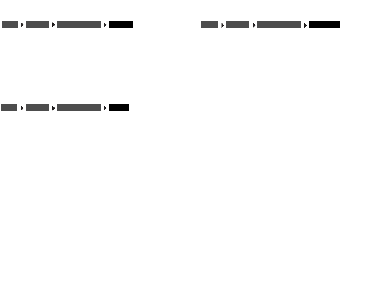
RV-5 Setup
3-65
POSITION TOP, CENTER, BOTTOM
Controls the vertical position of the two-line status on the display
device screen. When set to TOP, the two-line status appears near the
top of the display device screen. When set to CENTER, the two-line
status is centered on the display device screen. When set to
BOTTOM, the two-line status appears near the bottom of the display
device screen. Refer to page 2-28 for more information about the
two-line status.
FORMAT SECAM, PAL, NTSC
Controls the compatibility between the video input connectors, the
video switcher and the display device. Select the setting that is
compatible with the source components and display device.
Note:
The FORMAT parameter affects the composite and S-Video output
connectors. It does not affect the component video output connector.
BACKGROUND ON, OFF
Activates and deactivates the menu background. When set to ON,
on-screen display menus appear over a solid blue or gray background
(depending on the display device). When set to OFF, on-screen
display menus appear over the video input signal.
Note:
When the BACKGROUND parameter is set to OFF, the on-screen display
will disappear if the display device is using the component video output
connector.
DISPLAYSSETUP ON-SCREEN DISPLAY POSITION
DISPLAYSSETUP ON-SCREEN DISPLAY FORMAT
DISPLAYSSETUP ON-SCREEN DISPLAY BACKGROUND
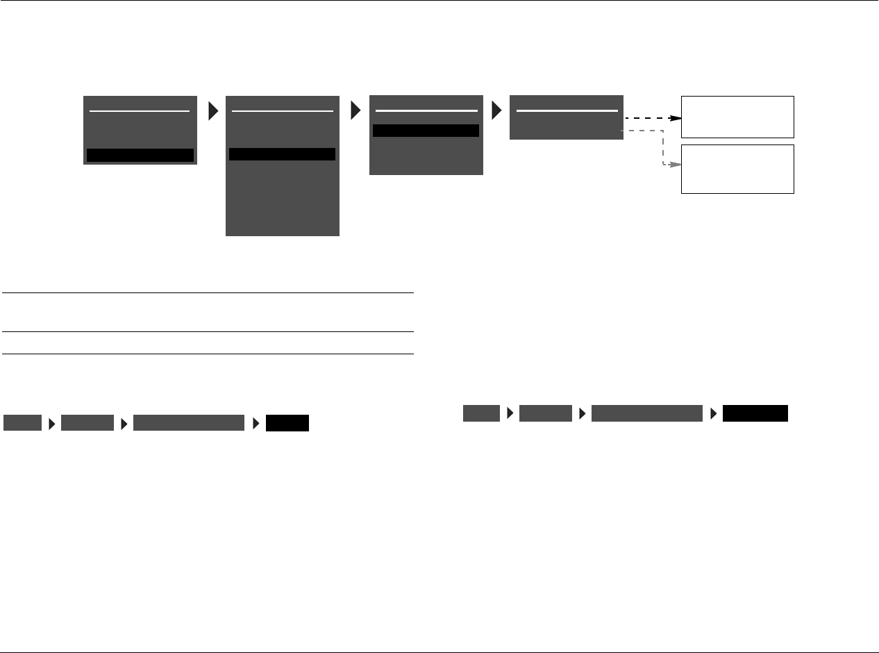
Setup Lexicon
3-66
FRONT-PANEL DISPLAY SETUP
Opens the FRONT PANEL DISPLAY menu, which is used to customize the front-panel display.
STATUS ALWAYS ON, 2 SECONDS, ALWAYS OFF
Activates and deactivates the front-panel display. When set to ALWAYS
ON, the front-panel display remains on at all times. When set to 2
SECONDS, the front-panel display appears for 2 seconds whenever the
input source changes or the RV-5 receives a command. When set to
ALWAYS OFF, the front-panel display remains off at all times.
Note:
When the FRONT PANEL DISPLAY menu STATUS parameter is set to
ALWAYS OFF, the front-panel display immediately disappears. Use the on-
screen display as a guide to reset the parameter to ALWAYS ON or 2
SECONDS.
BRIGHTNESS 100%,75%, 50%, 25%
Controls the brightness of front-panel display characters. When a
setting is selected, front-panel display illumination automatically
adjusts to the selected brightness.
ALWAYS ON
2 SECONDS
ALWAYS OFF
DISPLAY SETUP
ON-SCREEN DISPLAY
FRONT PANEL DISPLAY
A/V SYNC DELAY
CUSTOM NAME
EDIT CUSTOM NAME
OFF
OFF
100%
FRONT PANEL DISPLAY
STATUS
BRIGHTNESS
ALWAYS ON
100%
75%
50%
25%
SETUP
INPUTS
SPEAKERS
I/O CONFIG
DISPLAYS
VOLUME CONTROLS
TRIGGER
TUNER SETUP
MAIN MENU
MODE ADJUST
AUDIO CONTROLS
TUNER PRESETS
LOCK OPTIONS
SETUP
LIVE! CALIBRATION
POWER MANAGEMENT
Parameter Default Setting Possible Settings
STATUS ALWAYS ON ALWAYS ON, 2 SECONDS,
ALWAYS OFF
BRIGHTNESS 100% 100%, 75%, 50%, 25%
DISPLAYSSETUP FRONT PANEL DISPLAY STATUS DISPLAYSSETUP FRONT PANEL DISPLAY BRIGHTNESS
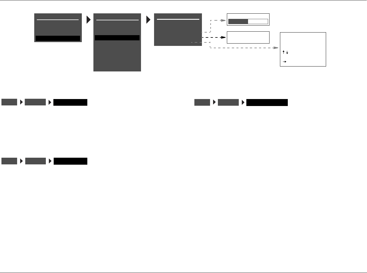
RV-5 Setup
3-67
A/V SYNC DELAY OFF, 1 to 60ms
Restores audio/video synchronization when using products such as
video processors that introduce a video signal delay. This parameter
can be used to set an audio signal delay to compensate for the video
signal delay.
CUSTOM NAME ON, OFF
Activates the display of a custom unit name, which appears when the
RV-5 is activated. When set to ON, the custom name scrolls across
the on-screen and front-panel displays when the RV-5 is activated.
When set to OFF, the custom name does not appear when the RV-5 is
activated. The custom name can be entered in the DISPLAY SETUP
menu EDIT CUSTOM NAME menu.
EDIT CUSTOM NAME
Opens the EDIT CUSTOM NAME menu shown below, which can be
used to create a custom unit name. When the CUSTOM parameter is
set to ON, the custom unit name appears in the on-screen and front-
panel displays when the RV-5 is activated.
To customize the name of the RV-5:
1. Follow the EDIT CUSTOM NAME menu path to open the EDIT
CUSTOM NAME drop-down menu shown below.
2. When the EDIT CUSTOM NAME drop-down menu opens, press
the remote control and arrow buttons to change the
character above the cursor (^).
3. When the desired character has been selected, press the arrow
button to advance to the next character space. The cursor will
automatically wrap to the first character space when the last
character space is passed.
4. Repeat steps 2 and 3 to enter the desired custom unit name.
5. When the desired custom unit name has been entered, press the
arrow button to close the EDIT CUSTOM NAME drop-down
menu and return to the DISPLAY SETUP menu.
DISPLAYSSETUP A/V SYNC DELAY
DISPLAY SETUP
ON-SCREEN DISPLAY
FRONT PANEL DISPLAY
A/V SYNC DELAY
OFF, 1 to 60ms
CUSTOM NAME
EDIT CUSTOM NAME
OFF
OFF ON
OFF EDIT CUSTOM NAME
RV-5
BUTTONS TO EDIT
UP TO 20 CHARACTERS
BUTTON TO ADVANCE
>
SETUP
INPUTS
SPEAKERS
I/O CONFIG
DISPLAYS
VOLUME CONTROLS
TRIGGER
TUNER SETUP
MAIN MENU
MODE ADJUST
AUDIO CONTROLS
TUNER PRESETS
LOCK OPTIONS
SETUP
LIVE! CALIBRATION
POWER MANAGEMENT
DISPLAYSSETUP CUSTOM NAME
DISPLAYSSETUP EDIT CUSTOM NAME
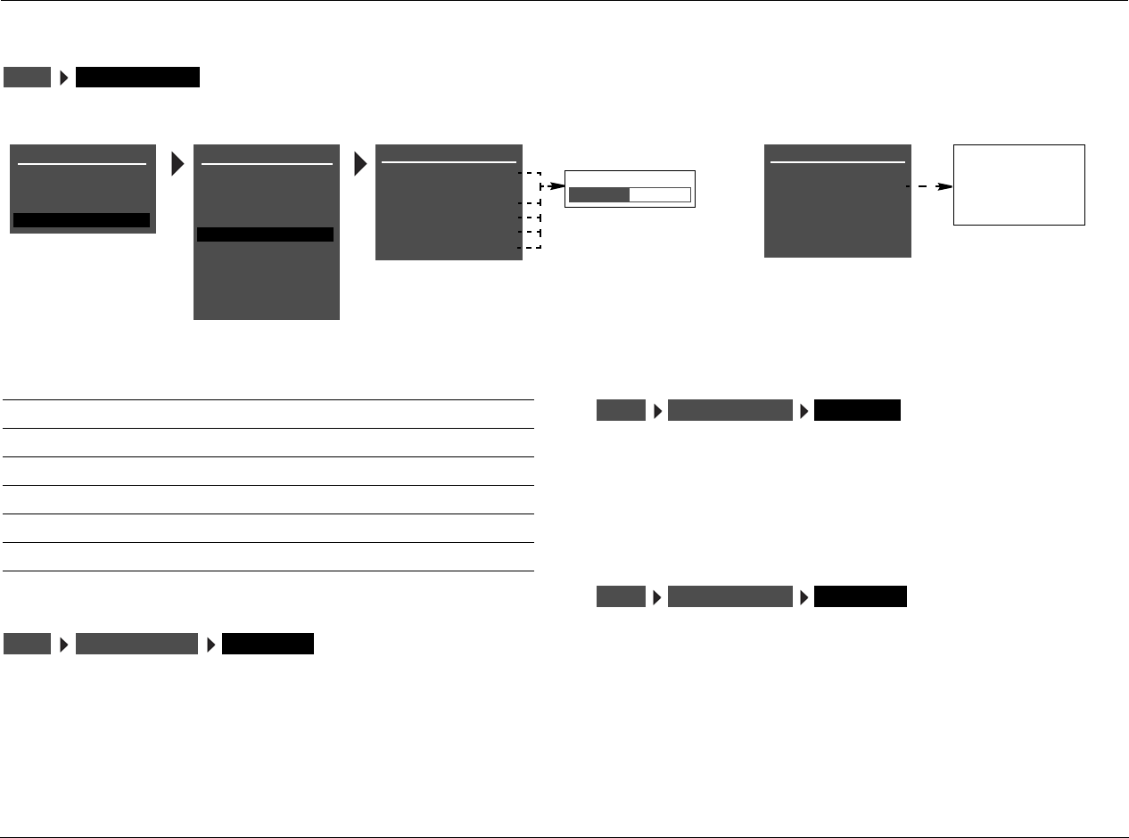
Setup Lexicon
3-68
VOLUME CONTROL SETUP
Opens the VOLUME CONTROL SETUP menu, which is used to configure Main Zone, Zone 2, Zone 3, and Headphone volume levels.
MAIN PWR ON LAST LVL, –80 to +12dB
Sets the Main Zone volume level that will be selected whenever the
Main Zone is activated. When set to LAST LVL, the Main Zone
activates at the volume level that was last selected in the previous
operating session.
MUTE LEVEL –40dB, –30dB, –20dB, –10dB, FULL MUTE
Sets the amount of attenuation that occurs in the Main Zone when the
front-panel or remote control Mute button is pressed. When set to FULL
MUTE, Main Zone volume level will be fully attenuated. Otherwise, Main
Zone volume level will be attenuated to the selected level.
Z2 PWR ON LAST LVL, –80 to +12dB
Sets the Zone 2 volume level that will be selected whenever Zone 2 is
activated. When set to LAST LVL, Zone 2 activates at the volume level
that was last selected in the previous operating session. LAST LVL is
displayed on power up if the Zone 2 was powered off using the Zone
2 Off button on the remote control or front panel.
SETUP VOLUME CONTROLS
MAIN MENU
MODE ADJUST
AUDIO CONTROLS
TUNER PRESETS
SETUP
INPUTS
SPEAKERS
I/O CONFIG
DISPLAYS
VOLUME CONTROLS
TRIGGER
TUNER SETUP
VOLUME CONTROL SETUP
MAIN PWR ON
MUTE LEVEL
Z2 PWR ON
LAST LVL, -80 to +12dB
-30dB
-30dB
-30dB
-10dB
-20dB
-30dB
-40dB
FULL MUTE
LOCK OPTIONS
Z2 PWR ON -30dB
VOLUME CONTROL SETUP
MAIN PWR ON
MUTE LEVEL
ZONE PWR ON
-30dB
-30dB
-30dB
MAX VOL +12dB
SETUP
LIVE! CALIBRATION
HEADPHONE -30dB
VOLUME CONTROL SETUP
MAIN PWR ON
MUTE LEVEL
Z2 PWR ON
-30dB
-30dB
-30dB
Z2 PWR ON -30dB
HEADPHONE -30dB
MAX VOLUME +12dB MAX VOLUME +12dB
POWER MANAGEMENT
Parameter Default
Setting Possible Settings
MAIN PWR ON –30dB LAST LVL, –80 to +12dB
MUTE LEVEL –30dB –40dB, –30dB, –20dB, –10dB, FULL
Z2 PWR ON –30dB LAST LVL, –80 to +12dB
Z3 PWR ON –30dB LAST LVL, –80 to +12dB
HEADPHONE –30dB LAST LVL, –80 to +12dB
MAX VOLUME –12dB –80 to +12dB
SETUP VOLUME CONTROLS MAIN PWR ON
SETUP VOLUME CONTROLS MUTE LEVEL
SETUP VOLUME CONTROLS ZONE PWR ON

RV-5 Setup
3-69
Z3 PWR ON LAST LVL, –80 to +12dB
Sets the Zone 3 volume level that will be selected whenever Zone 3 is
activated. When set to LAST LVL, Zone 3 activates at the volume level
that was last selected in the previous operating session. LAST LVL is
displayed on power up if the Zone 3 was powered off using the Zone
3 Off button on the remote control or front panel.
HEADPHONE LAST LVL, –80 to +12dB
Sets the Headphone volume level that will be selected whenever
headphones are plugged in to the RV-5. When set to LAST LVL, the
headphones will activate at the last volume level that was selected
when they were last plugged in. When the headphones are
unplugged, the volume will revert to the MAIN PWR ON setting.
MAX VOLUME -80 TO +12dB
Selects the maximum volume level for the Main Zone. When a value
is selected, the RV-5 automatically sets Main Zone volume level to the
selected value when the current level is higher.
SETUP VOLUME CONTROLS ZONE PWR ON
SETUP VOLUME CONTROLS ZONE PWR ON
SETUP VOLUME CONTROLS MAX VOLUME
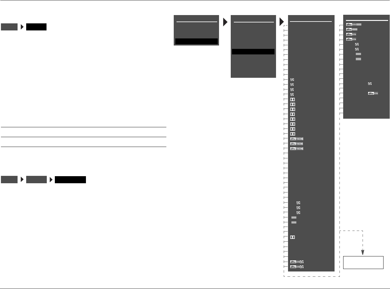
Setup Lexicon
3-70
TRIGGER SETUP
Selecting the SETUP menu TRIGGER option opens the
TRIGGER SETUP menu shown to the right, which can be used
to configure the trigger output connector labeled 1. The RV-5
rear panel houses two 12V DC trigger output connectors. The
connector labeled PWR – the power trigger output connector
– is not configurable. It is activated when the RV-5 is activated,
and deactivated when the RV-5 is deactivated. The trigger
output connector labeled 1 can be configured for remote or
program operation.
REMOTE ONLY ON, OFF
Configures the trigger output connector labeled 1 for remote
operation. When set to ON, this connector is configured for
remote operation. The remote control play and stop buttons
turns the trigger on and off. The RV-5 ignores all other
TRIGGER SETUP menu parameter settings. When set to OFF,
the trigger output connector labeled 1 is not configured for
remote operation. It can be configured for program operation.
Parameter Default Setting Possible Settings
REMOTE ONLY ON ON, OFF
Program Operation OFF ON, OFF
TRIGGERSETUP
MAIN MENU SETUP
INPUTS
SPEAKERS
I/O CONFIG
DISPLAYS
VOLUME CONTROLS
TRIGGER
TUNER SETUP
ON
OFF
* TRIGGER SETUP menu
listening mode names
are fixed, meaning
these names do not
change when certain
encoding is present. For
instance, the 5.1 THX
SurEX listening mode
label appears whether
THX Ultra2, THX Sur-
round EX, or no encod-
ing is engaged.
LOCK OPTIONS
TRIGGER SETUP
OFF
MUSIC OFF
OFF
2-CHAN OFF
5.1a FILM OFF
5.1a MUSIC OFF
5.1a SurEX OFF
5.1a MUSIC OFF
5.1a STANDARD OFF
5.1a 2-CHANNEL OFF
5.1a BYPASS OFF
2CH BYPASS OFF
HEADPHONE OFF
HEADPHONE 5.1 OFF
HEADPHONE OFF
HEADPHONE 5.1a OFF
LIVE! SMALL OFF
LIVE! MED OFF
LIVE! LARGE OFF
TRIGGER SETUP
REMOTE ONLY ON
DVD1 OFF
DVD2 OFF
SAT OFF
VCR OFF
TV OFF
CD OFF
TUNER OFF
PHONO OFF
ZONE2 INPUTS OFF
ZONE3 INPUTS OFF
FILM OFF
TV OFF
MUSIC OFF
MUSIC SURR OFF
PLIIx + THX OFF
PLIIx MOV OFF
PLIIx MUS OFF
PLII+ THX OFF
PLII MOVIE OFF
PLII MUSIC OFF
PL + THX OFF
PRO LOGIC OFF
+ THX OFF
CIN OFF
MUSIC OFF
NIGHTCLUB OFF
CONCERT HHALL OFF
CHURCH OFF
CATHEDRAL OFF
PANORAMA OFF
2-CH SURROUND OFF
2-CHANNEL OFF
MONO LOGIC OFF
MONO SURROUND OFF
MONO OFF
5.1 FILM OFF
5.1 TV OFF
5.1 MUSIC OFF
SurEX OFF
MUSIC OFF
5.1 PLIIx MOV OFF
5.1 PLIIx MUS OFF
DIGITAL EX OFF
5.1 2-CHANNEL OFF
5.1 MONO LOGIC OFF
5.1 MONO SURR OFF
5.1 MONO OFF
FILM OFF
MAIN MENU
MODE ADJUST
AUDIO CONTROLS
TUNER PRESETS
SETUP
LIVE! CALIBRATION
POWER MANAGEMENT
TRIGGERSETUP REMOTE ONLY
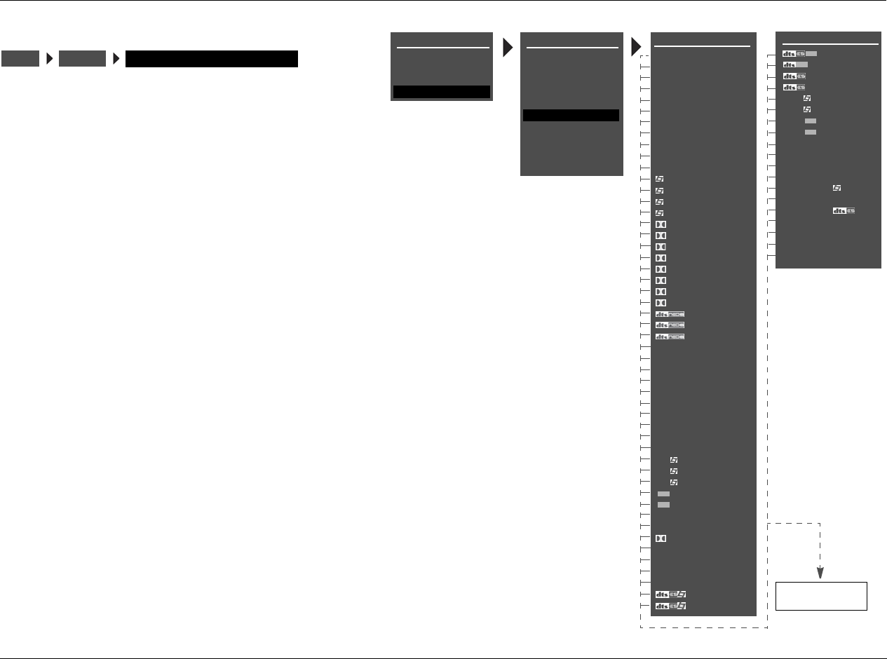
RV-5 Setup
3-71
PROGRAM OPERATION PARAMETERS ON, OFF
Configure the trigger output connector labeled 1 for
program operation. All TRIGGER SETUP menu parameters–
except the REMOTE ONLY parameter–are considered
program operation parameters. The connector can be
associated with multiple inputs and listening modes at the
same time.
When the REMOTE ONLY parameter is set to OFF and
program operation parameters are set to ON, the trigger
output connector labeled 1 is associated with the corre-
sponding Main Zone inputs, Main Zone listening modes
or Zone 2 inputs. (The connector cannot be associated
with individual Zone 2 inputs; rather, it can be associated
with the Zone 2 inputs as a group.) When configured for
program operation, the connector is activated when the
corresponding inputs and listening modes are selected
and deactivated when the corresponding inputs and
listening modes are deselected.
Note:
When the CUSTOM menu RESET MODE option is selected to
restore the factory default version of the selected listening
mode, the corresponding TRIGGER SETUP menu listening
mode parameter is automatically set to OFF.
TRIGGERSETUP (PROGRAM OPERATION PARAMETER)
MAIN MENU SETUP
INPUTS
SPEAKERS
I/O CONFIG
DISPLAYS
VOLUME CONTROLS
TRIGGER
TUNER SETUP
ON
OFF
* TRIGGER SETUP menu
listening mode names
are fixed, meaning
these names do not
change when certain
encoding is present. For
instance, the 5.1 THX
SurEX listening mode
label appears whether
THX Ultra2, THX Sur-
round EX, or no encod-
ing is engaged.
LOCK OPTIONS
TRIGGER SETUP
OFF
MUSIC OFF
OFF
2-CHAN OFF
5.1a FILM OFF
5.1a MUSIC OFF
5.1a SurEX OFF
5.1a MUSIC OFF
5.1a STANDARD OFF
5.1a 2-CHANNEL OFF
5.1a BYPASS OFF
2CH BYPASS OFF
HEADPHONE OFF
HEADPHONE 5.1 OFF
HEADPHONE OFF
HEADPHONE 5.1a OFF
LIVE! SMALL OFF
LIVE! MED OFF
LIVE! LARGE OFF
TRIGGER SETUP
REMOTE ONLY ON
DVD1 OFF
DVD2 OFF
SAT OFF
VCR OFF
TV OFF
CD OFF
TUNER OFF
PHONO OFF
ZONE2 INPUTS OFF
ZONE3 INPUTS OFF
FILM OFF
TV OFF
MUSIC OFF
MUSIC SURR OFF
PLIIx + THX OFF
PLIIx MOV OFF
PLIIx MUS OFF
PLII+ THX OFF
PLII MOVIE OFF
PLII MUSIC OFF
PL + THX OFF
PRO LOGIC OFF
+ THX OFF
CIN OFF
MUSIC OFF
NIGHTCLUB OFF
CONCERT HHALL OFF
CHURCH OFF
CATHEDRAL OFF
PANORAMA OFF
2-CH SURROUND OFF
2-CHANNEL OFF
MONO LOGIC OFF
MONO SURROUND OFF
MONO OFF
5.1 FILM OFF
5.1 TV OFF
5.1 MUSIC OFF
SurEX OFF
MUSIC OFF
5.1 PLIIx MOV OFF
5.1 PLIIx MUS OFF
DIGITAL EX OFF
5.1 2-CHANNEL OFF
5.1 MONO LOGIC OFF
5.1 MONO SURR OFF
5.1 MONO OFF
FILM OFF
MAIN MENU
MODE ADJUST
AUDIO CONTROLS
TUNER PRESETS
SETUP
LIVE! CALIBRATION
POWER MANAGEMENT
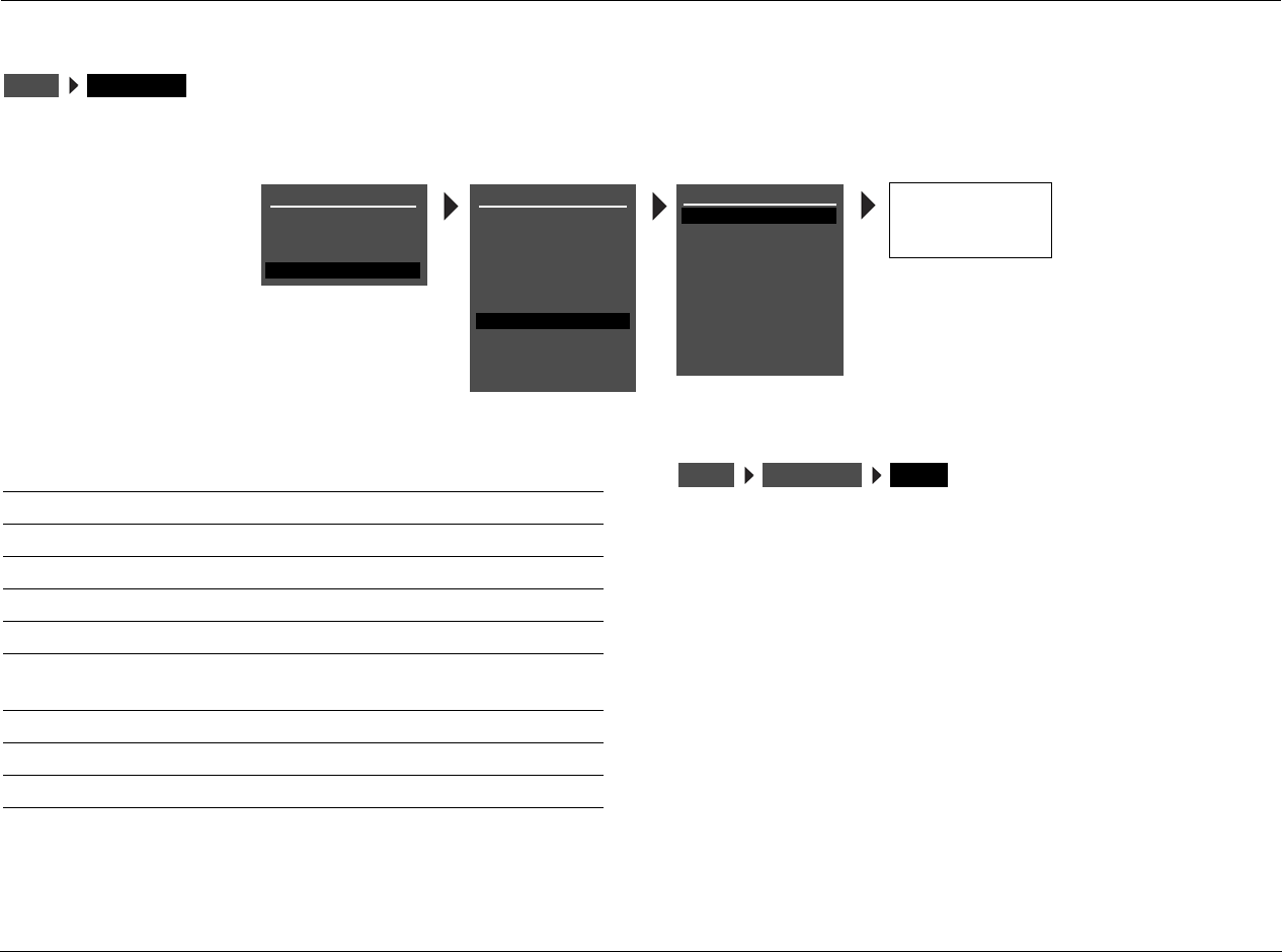
Setup Lexicon
3-72
TUNER SETUP
Selecting the SETUP menu TUNER SETUP option opens the TUNER SETUP menu, which is used to configure the AM/FM radio tuner.
REGION USA, EUROPE, JAPAN, E. EUR
Sets the tuner region. The four regions are USA, EUROPE, JAPAN and
E. EUR. The table on the next page lists the band limits and incre-
ments for these regions.
Note:
The tuner user interface will not allow illegal frequencies to be entered. It
will always set at the closest valid frequency. For example, if the RV-5 has
USA set as the current region, entering 107.8MHz will result in 107.9MHz
being the actual tuner frequency. If the value is less than the lowest
frequency, it will set it to LO LIMIT for the appropriate region. Likewise, if
the dialed value is larger than the highest allowed frequency, it will
actually set it to the HI LIMIT for the appropriate region.
SETUP TUNER SETUP
MAIN MENU
MODE ADJUST
AUDIO CONTROLS
TUNER PRESETS
SETUP
INPUTS
SPEAKERS
I/O CONFIG
DISPLAYS
VOLUME CONTROLS
TRIGGER
TUNER SETUP
TUNER SETUP
REGION
SCAN SENS
AUTOLOAD
USA
LOW
LOCK OPTIONS
CLEAR ALL
SETUP
LIVE! CALIBRATION
USA
EUROPE
JAPAN
E. EUR
TUNER PRESETS
DISPLAY
RADIO TEXT
SCROLL RATE
AUTO FREQUENCY
RDS NAME
ON
MEDIUM
ON
POWER MANAGEMENT
Parameter Default
Setting Possible Settings
REGION USA USA, EUROPE, JAPAN, E. EUR
SCAN SENS LOW LOW, MED, HIGH
AUTOLOAD N/A N/A
CLEAR ALL N/A N/A
TUNER PRESETS N/A N/A
DISPLAY RDS NAME RDS NAME, PRESET NAME,
FREQUENCY
RADIO TEXT ON ON, OFF
SCROLL RATE MEDIUM SLOW, MEDIUM, FAST
AUTO FREQUENCY ON ON, OFF
SETUP TUNER SETUP REGION
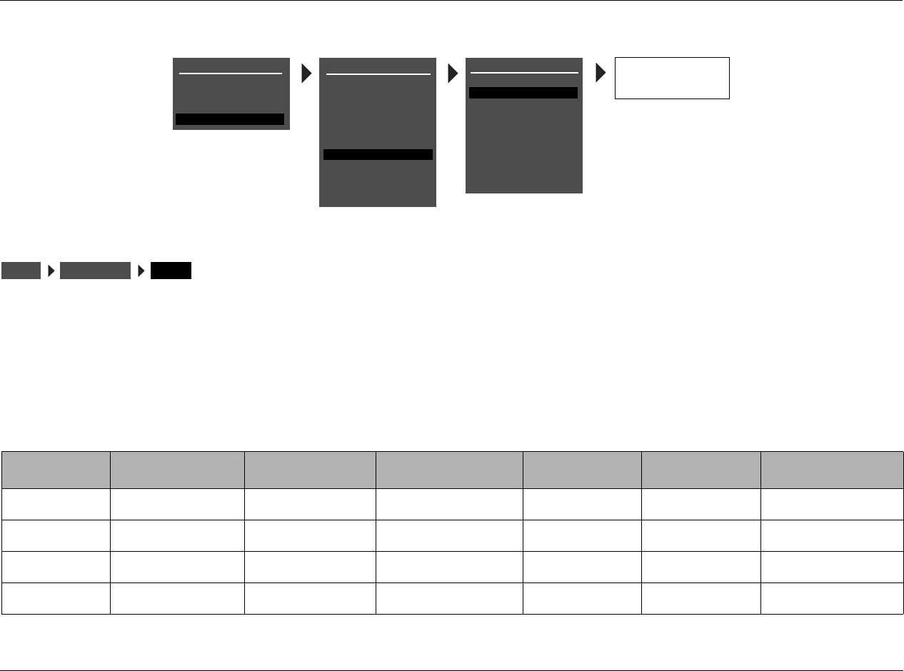
RV-5 Setup
3-73
SCAN SENS LOW, MED, HIGH
Selects the Scan Sensitivity parameter, which can be used to set the
threshold the system will use to tune to a new station. The default
setting is LOW sensitivity (only the strongest station frequencies will
tune). If the LOW setting does not tune enough stations, try the MED
(medium) or HIGH settings.
TUNER REGION BAND LIMIT AND INCREMENTS
MAIN MENU
MODE ADJUST
AUDIO CONTROLS
TUNER PRESETS
SETUP
INPUTS
SPEAKERS
I/O CONFIG
DISPLAYS
VOLUME CONTROLS
TRIGGER
TUNER SETUP
TUNER SETUP
REGION
SCAN SENS
AUTOLOAD
USA
LOW
LOCK OPTIONS
CLEAR ALL
SETUP
LIVE! CALIBRATION
LOW
MED
HIGH
TUNER PRESETS
DISPLAY
RADIO TEXT
SCROLL RATE
AUTO FREQUENCY
RDS NAME
ON
MEDIUM
ON
POWER MANAGEMENT
SETUP TUNER SETUP REGION
REGION FM LO LIMIT FM HI LIMIT FM INCREMENT AM LO LIMIT AM HI LIMIT AM INCREMENT
USA 87.90MHZ 107.90MHZ 200 KHZ/.2MHZ 520KHZ 1720KHZ 10KHZ
EUROPE 87.50MHZ 108.00MHZ 50KHZ/.05MHZ 520KHZ 1602KHZ 9KHZ
JAPAN 76.00MHZ 91.00MHZ 50KHZ/.05MHZ 522KHZ 1720KHZ 9KHZ
E. EUR 64.00MHZ 76.00MHZ 50KHZ/.05MHZ 520KHZ 1720KHZ 9KHZ
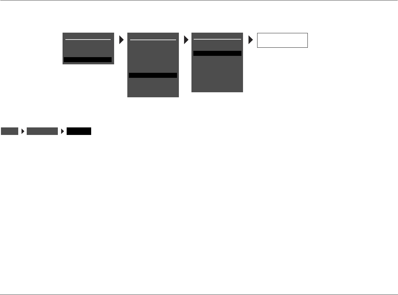
Setup Lexicon
3-74
TUNER SETUP (continued)
AUTOLOAD
Automatically scans and stores presets for the currently selected
frequency band.
To select the AUTOLOAD option, highlight AUTOLOAD in the TUNER
SETUP menu and press the right () arrow. The message “PRESS
RIGHT TO START AUTOLOAD” appears in the on-screen and front-
panel displays.
• To cancel the AUTOLOAD command, press the left () arrow.
• AUTOLOAD skips presets with previously stored values and uses
the next available preset.
• Once all available stations have been scanned, or if any TUNER
button is pressed (including the remote’s buttons), AUTOLOAD
will stop.
• To autoload stations from the other frequency band, select that
band and restart AUTOLOAD.
Note:
Presets are saved when the unit is powered down. Because the
AUTOLOAD function preserves any existing presets, consider using the
CLEAR ALL function before using AUTOLOAD. Note that some channels
may be repeated in the preset section if AUTOLOAD is used more than
once since the last CLEAR ALL.
PRESS RIGHT J
TO START AUTOLOAD
MAIN MENU
MODE ADJUST
AUDIO CONTROLS
TUNER PRESETS
SETUP
INPUTS
SPEAKERS
I/O CONFIG
DISPLAYS
VOLUME CONTROLS
TRIGGER
TUNER SETUP
TUNER SETUP
REGION
SCAN SENS
AUTOLOAD
USA
LOW
LOCK OPTIONS
CLEAR ALL
SETUP
LIVE! CALIBRATION
TUNER PRESETS
DISPLAY
RADIO TEXT
SCROLL RATE
AUTO FREQUENCY
RDS NAME
ON
MEDIUM
ON
POWER MANAGEMENT
SETUP TUNER SETUP AUTOLOAD
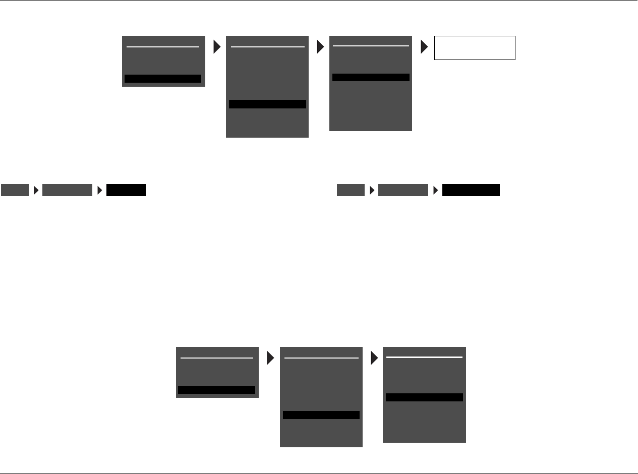
RV-5 Setup
3-75
CLEAR ALL
Clears all of the presets. When this option is highlighted, press the
right () arrow to select. The message “PRESS RIGHT TO CLEAR
ALL PRESETS” will appear in the on-screen and front-panel displays.
(Press the left () arrow to cancel the CLEAR ALL command.)
This should be used after all presets have been entered but it is
desired to rescan in order to obtain new presets. For example, if you
have moved to a new city, it would be necessary to clear all existing
presets and scan for local stations.
TUNER PRESETS
This selection provides an alternative access point to the TUNER
PRESETS menu. For more information, see “Tuner Presets” on
page 5-2.
SETUP TUNER SETUP CLEAR ALL
PRESS RIGHT J
TO CLEAR ALL PRESETS
MAIN MENU
MODE ADJUST
AUDIO CONTROLS
TUNER PRESETS
SETUP
INPUTS
SPEAKERS
I/O CONFIG
DISPLAYS
VOLUME CONTROLS
TRIGGER
TUNER SETUP
TUNER SETUP
REGION
SCAN SENS
AUTOLOAD
USA
LOW
LOCK OPTIONS
CLEAR ALL
SETUP
LIVE! CALIBRATION
TUNER PRESETS
DISPLAY
RADIO TEXT
SCROLL RATE
AUTO FREQUENCY
RDS NAME
ON
MEDIUM
ON
POWER MANAGEMENT
SETUP TUNER SETUP TUNER PRESETS
MAIN MENU
MODE ADJUST
AUDIO CONTROLS
TUNER PRESETS
SETUP
INPUTS
SPEAKERS
I/O CONFIG
DISPLAYS
VOLUME CONTROLS
TRIGGER
TUNER SETUP
TUNER SETUP
REGION
SCAN SENS
AUTOLOAD
USA
LOW
LOCK OPTIONS
CLEAR ALL
SETUP
LIVE! CALIBRATION
TUNER PRESETS
DISPLAY
RADIO TEXT
SCROLL RATE
AUTO FREQUENCY
RDS NAME
ON
MEDIUM
ON
POWER MANAGEMENT
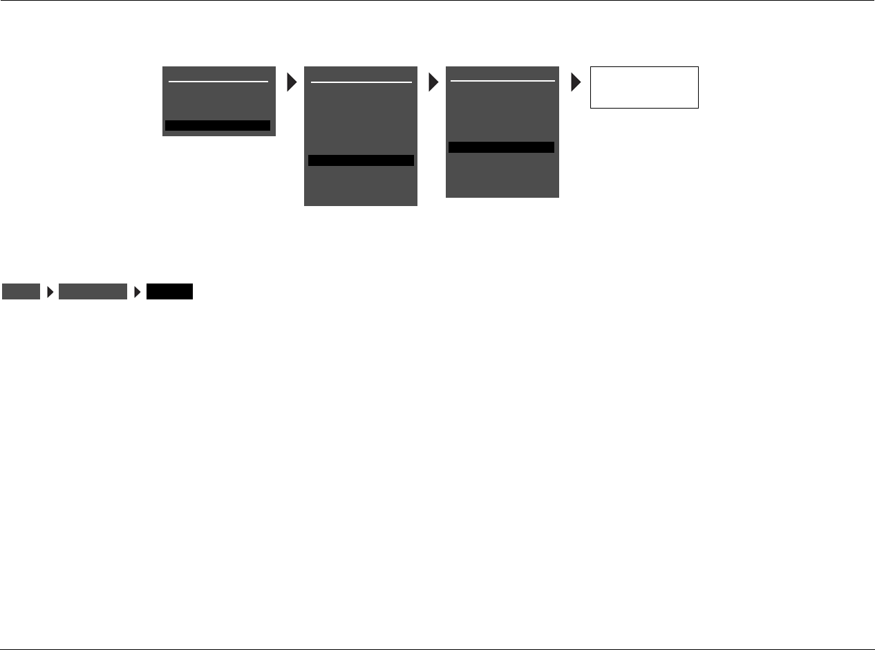
Setup Lexicon
3-76
TUNER SETUP (continued)
DISPLAY RDS NAME, PRESET NAME, FREQUENCY
Identifies the current channel setting, in the top right corner of the
OSD and front panel display. There are three possible selections: RDS
NAME, PRESET NAME, and FREQUENCY. The default setting is RDS
NAME.
PRESET NAME displays the name given to the preset frequency of the
currently selected channel. If the current channel is not a tuner
preset, then the channel frequency will be displayed.
RDS NAME displays the station's Program Service (PS) name, which is
intended to be used to identify a station or station program. If the
RDS information is not available, then the channel frequency will be
displayed.
FREQUENCY displays the actual frequency value of the channel
selected.
Note:
In the US, some stations broadcast other information in place of the
Program Service (PS) name, such as a text messaging feature similar to
Radio Text (RT). This can make it difficult to identify the station. You may
wish to select PRESET NAME instead of an RSD NAME in this instance.
RDS NAME
PRESET NAME
FREQUENCY
MAIN MENU
MODE ADJUST
AUDIO CONTROLS
TUNER PRESETS
SETUP
INPUTS
SPEAKERS
I/O CONFIG
DISPLAYS
VOLUME CONTROLS
TRIGGER
TUNER SETUP
TUNER SETUP
REGION
SCAN SENS
AUTOLOAD
USA
LOW
LOCK OPTIONS
CLEAR ALL
SETUP
LIVE! CALIBRATION
TUNER PRESETS
DISPLAY
RADIO TEXT
SCROLL RATE
AUTO FREQUENCY
RDS NAME
ON
MEDIUM
ON
POWER MANAGEMENT
SETUP TUNER SETUP DISPLAY
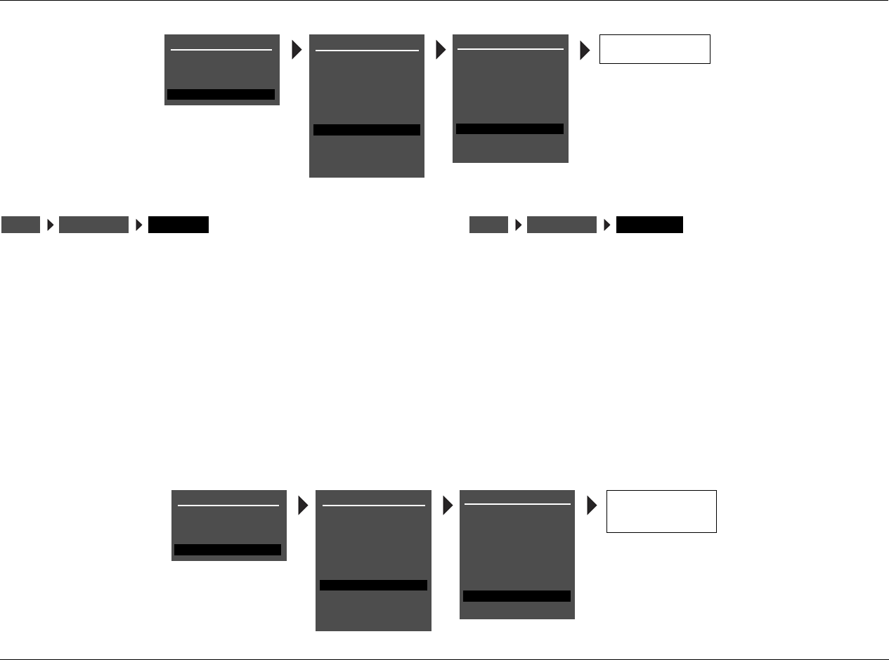
RV-5 Setup
3-77
RADIO TEXT ON, OFF
Activates the RADIO TEXT (RT) feature. Radio Text is presented as
scrolling text in the bottom row of the front-panel and on-screen
displays. Radio text can contain up to 64 characters and whatever
text the station broadcasts - such as the title and performer of the
current song, the station call letters or the station byline. Not all
stations broadcast RT. When tuned to a station that broadcasts Radio
Text, it will take approximately ten seconds to display the text.
When Radio Text is active, additional information is displayed in the
scrolling text. After the RT from the radio station has finished
scrolling, double asterisks (**) are displayed, followed by the currently
set listening mode, volume level, and tuner frequency. A second set
of double asterisks identifies the end of the tuner information and the
beginning repeat of the station's Radio Text.
SCROLL RATE SLOW, MEDIUM, FAST
Controls the scrolling speed of the Radio Text. The default setting is
MEDIUM. For faster text scrolling, select FAST. For slower text
scrolling, select SLOW.
SETUP TUNER SETUP RADIO TEXT
ON
OFF
MAIN MENU
MODE ADJUST
AUDIO CONTROLS
TUNER PRESETS
SETUP
INPUTS
SPEAKERS
I/O CONFIG
DISPLAYS
VOLUME CONTROLS
TRIGGER
TUNER SETUP
TUNER SETUP
REGION
SCAN SENS
AUTOLOAD
USA
LOW
LOCK OPTIONS
CLEAR ALL
SETUP
LIVE! CALIBRATION
TUNER PRESETS
DISPLAY
RADIO TEXT
SCROLL RATE
AUTO FREQUENCY
RDS NAME
ON
MEDIUM
ON
POWER MANAGEMENT
SETUP TUNER SETUP SCROLL RATE
SLOW
MEDIUM
FAST
MAIN MENU
MODE ADJUST
AUDIO CONTROLS
TUNER PRESETS
SETUP
INPUTS
SPEAKERS
I/O CONFIG
DISPLAYS
VOLUME CONTROLS
TRIGGER
TUNER SETUP
TUNER SETUP
REGION
SCAN SENS
AUTOLOAD
USA
LOW
LOCK OPTIONS
CLEAR ALL
SETUP
LIVE! CALIBRATION
TUNER PRESETS
DISPLAY
RADIO TEXT
SCROLL RATE
AUTO FREQUENCY
RDS NAME
ON
MEDIUM
ON
POWER MANAGEMENT
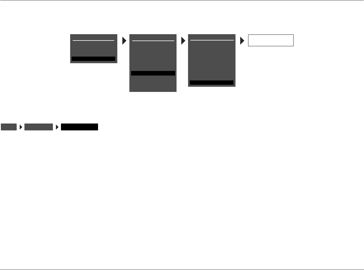
Setup Lexicon
3-78
TUNER SETUP (continued)
AUTO FREQUENCY ON, OFF
Checks for alternate frequency broadcasts in case of station drop out
or signal fade. The default setting is ON. Many radio stations
broadcast on several frequencies simultaneously. When active, AUTO
FREQUENCY checks for these alternate frequency broadcasts when
signal failure is detected.
If the main frequency drops out and AUTO FREQUENCY is activated,
the volume will mute briefly until the alternate broadcast is received.
AUTO FREQUENCY will only switch to a new frequency when
the following conditions are met:
• The main frequency signal starts to fade.
• The channel identification of the alternate frequency is an exact
match of the currently selected frequency.
• The alternate frequency detected has a stronger signal strength
than the currently selected frequency.
• The AUTO FREQUENCY feature is ON.
ON
OFF
MAIN MENU
MODE ADJUST
AUDIO CONTROLS
TUNER PRESETS
SETUP
INPUTS
SPEAKERS
I/O CONFIG
DISPLAYS
VOLUME CONTROLS
TRIGGER
TUNER SETUP
TUNER SETUP
REGION
SCAN SENS
AUTOLOAD
USA
LOW
LOCK OPTIONS
CLEAR ALL
SETUP
LIVE! CALIBRATION
TUNER PRESETS
DISPLAY
RADIO TEXT
SCROLL RATE
AUTO FREQUENCY
RDS NAME
ON
MEDIUM
ON
POWER MANAGEMENT
SETUP TUNER SETUP AUTO FREQUENCY
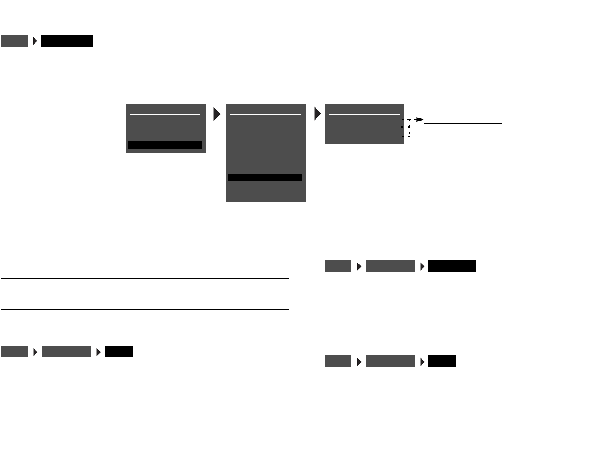
RV-5 Setup
3-79
LOCK OPTIONS
Selecting the SETUP menu LOCK OPTIONS option opens the LOCK OPTIONS menu, which is used to protect MODE ADJUST, AUDIO CONTROLS
and SETUP menu branch parameter settings from accidental changes.
MODES LOCKED, UNLOCKED
Controls MODE ADJUST menu branch settings, which includes all lis-
tening mode menu settings. When set to LOCKED, these settings
cannot be adjusted. When set to UNLOCKED, these settings can be
adjusted.
AUDIO CNTRL LOCKED, UNLOCKED
Controls AUDIO CONTROLS menu branch settings. When set to
LOCKED, these settings cannot be adjusted. When set to
UNLOCKED, these settings can be adjusted.
SETUP LOCKED, UNLOCKED
Controls SETUP menu branch settings. When set to LOCKED, these
settings cannot be adjusted. When set to UNLOCKED, these settings
can be adjusted.
SETUP LOCK OPTIONS
LOCK OPTIONS
MODES
AUDIO CNTRL
SETUP
UNLOCKED
UNLOCKED
UNLOCKED
LOCKED
UNLOCKED
MAIN MENU
MODE ADJUST
AUDIO CONTROLS
TUNER PRESETS
SETUP
INPUTS
SPEAKERS
I/O CONFIG
DISPLAYS
VOLUME CONTROLS
TRIGGER
TUNER SETUP
LOCK OPTIONS
SETUP
LIVE! CALIBRATION
POWER MANAGEMENT
Parameter Default Setting Possible Settings
MODES UNLOCKED LOCKED, UNLOCKED
AUDIO CNTRL UNLOCKED LOCKED, UNLOCKED
SETUP UNLOCKED LOCKED, UNLOCKED
SETUP LOCK OPTIONS MODES
SETUP LOCK OPTIONS AUDIO CNTRL
SETUP LOCK OPTIONS SETUP

Setup Lexicon
3-80

4
Audio & Video Controls
Audio Controls............................................................................4-2
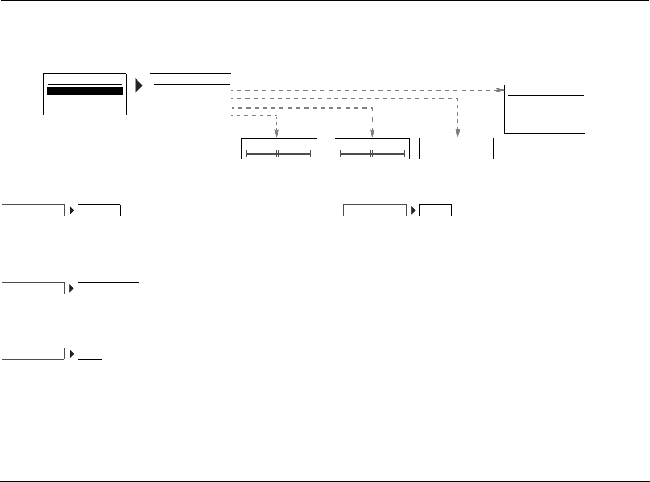
Audio & Video Controls Lexicon
4-2
AUDIO CONTROLS
Selecting AUDIO CONTROLS opens the AUDIO CONTROLS menu, which is used to customize the audio output connectors.
EQ PRESET PRESET 1, PRESET 2, PRESET 3, ACTIVE PS
The RV-5 provides 3 preset controls for the EQ plus one user-
controlled setting.
TONE CONTROLS OFF, ON
Actives or deactivates the tone controls.
BASS –0.5dB to +5.0dB
Controls the amount of low-frequency boost or cut applied to the
audio output connectors labeled Front L/R, Center, and Subwoofer.
The BASS Parameter Settings graph on the next page indicates the
frequency response of all BASS parameter settings. Bass setting can
be changed in 2dB increments.
TREBLE –5.0dB to +5.0dB
Controls the amount of high-frequency boost or cut applied to the
audio output connectors labeled Front L/R and Center. The TREBLE
Parameter Settings graph on the next page indicates the frequency
response of all TREBLE parameter settings. Treble setting can be
changed in 2dB increments.
MAIN MENU
AUDIO CONTROLS
VIDEO CONTROLS
AUDIO CONTROLS
EQ PRESET
TONE CONTROLS
BASS
TREBLE
AUDIO STATUS
+0.0dB
+0.0dB
OFF
ON
OFF
-5.0 to +5.0dB -5.0 to +5.0dB
SETUP
PRESET 1: BYPASS
PRESET 2: BYPASS
PRESET 3: BYPASS
ACTIVE PS: USER
EQ PRESET
AUDIO CONTROLS EQ PRESET
AUDIO CONTROLS TONE CONTROLS
AUDIO CONTROLS BASS
AUDIO CONTROLS TREBLE
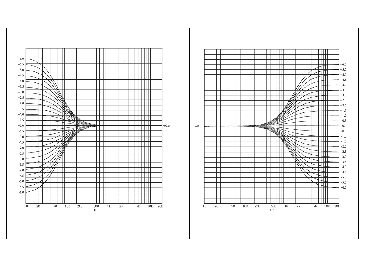
RV-5 Audio & Video Controls
4-3
The BASS parameter controls the amount of low-frequency boost or cut applied to the
audio output connectors labeled Front L/R, Center and Sub.
BASS Parameter Settings
The TREBLE parameter controls the amount of high-frequency boost or cut
applied to the audio output connectors labeled Front L/R and Center.
TREBLE Parameter Settings
Audio & Video Controls Lexicon
4-4
AUDIO CONTROLS (continued)
AUDIO STATUS
The AUDIO STATUS menu is an information-only menu identifying
the current audio status of the RV-5 unit. Input identifies the actual
audio source. Name identifies the title of the RV-5 as defined by the
user. Connector identifies the actual audio input port selected on
the rear panel. Audio identifies the audio input selected in the
control panel. Listen Mode identifies the currently selected
surround mode. Type identifies the currently selected surround
type.
MAIN MENU
AUDIO CONTROLS
VIDEO CONTROLS
AUDIO CONTROLS
EQ PRESET
TONE CONTROLS
BASS
TREBLE
AUDIO STATUS
+0.0dB
+0.0dB
OFF
SETUP
INPUT:
NAME:
CONNECTOR:
AUDIO:
AUDIO STATUS
LISTEN TYPE:
TYPE:
DVD 1
HDMI 2
UNLOCK
STEREO
2-CHANNEL
AUDIO CONTROLS AUDIO STATUS
RV-5 Audio & Video Controls
4-5
VIDEO CONTROLS
Selecting VIDEO CONTROLS opens the VIDEO CONTROLS menu, which is used to customize the video connectors.
4:3 IN > 16:9 DISP ORIGINAL, AUTO, STRETCH 2, 2.35 LB
STRETCH, 2.35 LB ZOOM, STRETCH, LB ZOOM
Identifies the display settings.
VIDEO STATUS
The VIDEO STATUS menu is an information-only menu identifying
the current video status of the RV-5 unit. Input Resol. identifies the
current input resolution setting. Copy Protection identifies the
current status of the copy protection mode. Video Process identifies
the current setting of the video processor. Output Resol. identifies
the current output resolution setting. Component Out identifies the
currently selected component output type. S-Video Out identifies
the currently selected S-video output type. Composite Out
identifies the currently selected composite output type.
MAIN MENU
AUDIO CONTROLS
VIDEO CONTROLS
VIDEO CONTROLS
4:3 IN > 16:9 DISP:
ORIGINAL
VIDEO STATUS
SETUP
AUTO
STRETCH 2
2.35 LB STRETCH
2.35 LB ZOOM
ORIGINAL
INPUT RESOL:
COPY PROTECTION:
VIDEO PROCESS:
OUTPUT RESOL:
VIDEO STATUS
COMPONENT OUT:
S-VIDEO OUT:
- - -
BYPASS
- - -
480i
OFF
COMPOSITE OUT:
OFF
OFF
STRETCH
LB ZOOM
AUDIO CONTROLS EQ PRESET
AUDIO CONTROLS VIDEO STATUS

Audio & Video Controls Lexicon
4-6

5
Tuner Presets
Tuner Presets ..............................................................................5-2
Tuner Presets Lexicon
5-2
TUNER PRESETS
Selecting TUNER PRESETS from the MAIN MENU displays a list of the pages of existing presets. The preset number, preset name (if available),
frequency and broadcast band is displayed.
In the US, each preset channel is identified by the station's call
letters, or what their broadcast information identifies as the call
letters. In Europe and Japan, each preset channel is identified by the
station's Program Service (PS) name. If RDS information is not
available, then the Preset name will be Preset XX, where XX is the
listed number location in the Preset menu for that position. For
example, if Preset #01 is FM 90.90 and the call letters are WABC,
then the name for that position is WABC.
To edit a preset, press the menu / arrows until the desired
preset is highlighted, then press the menu arrow to open the
parameters menu for the selected preset.
MAIN MENU
MODE ADJUST
AUDIO CONTROLS
TUNER PRESETS
TUNER PRESETS
PAGE 1
PAGE 2
PAGE 3
PAGE 4
STATION
SETUP
TUNER PRESETS
01
02
03
04
05
06
0.00FM
0.00FM
0.00FM
0.00FM
0.00FM
0.00FM
07 0.00FM
08 0.00FM
09
10
0.00FM
0.00FM PRESS MENU
TO CLEAR PRESET
EDIT STATION NAME
BUTTONS TO EDIT
UP TO 8 CHARACTERS
BUTTON TO ADVANCE
EDIT PRESET 1
FREQUENCY
BAND
LISTEN TO PRESET
NAME
CLEAR PRESET
Each tuner preset page
allows up to 10 preset
stations.
0.00
FM
LOADED
Parameter
LISTEN TO PRESET
NAME
CLEAR PRESET

RV-5 Tuner Presets
5-3
LISTEN TO PRESET
Loads the current preset station. Press the menu arrow to load
the station preset. The front panel and on-screen display will display
“STATION LOADED.”
NAME
Edits the station name. The station name can be up to 8 characters
long. The available characters are letters A to Z, numbers 0 to 9,
and 10 additional symbols: ., -, +, :, (, ), !, @, # or a blank space.
CLEAR PRESET
Clears the current preset entry. The front-panel and on-screen
display will display “PRESS MENU TO CLEAR PRESET.” Press the
menu arrow to cancel without clearing the preset.
TUNER PRESETS LISTEN TO PRESETPAGE 1
01
TUNER PRESETS NAMEPAGE 1
01
TUNER PRESETS CLEAR PRESET
PAGE 1
01

Tuner Presets Lexicon
5-4

6
Mode Adjust
Mode Adjust ...............................................................................6-2
Listening Mode Activation...........................................................6-2
Listening Mode Descriptions .......................................................6-4
Listening Mode Menu Option and Parameter Descriptions........6-39
Mode – Parameter Relationships ...............................................6-47
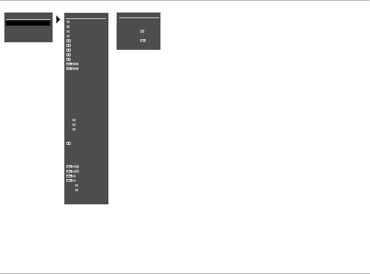
Mode Adjust Lexicon
6-2
MODE ADJUST
Selecting the MODE ADJUST option opens the MODE ADJUST menu, which is
used to select a listening mode for adjustment. When the MODE ADJUST menu
opens, the currently activated Main Zone listening mode is highlighted.
Selecting a listening mode does not activate that listening mode
for the current Main Zone input source. Rather, selecting a listening
mode opens the corresponding listening mode menu, which is used to
customize the selected listening mode. These adjustments are applied
when the listening mode is selected with one of the methods described in
the Listening Mode Activation section that begins below.
LISTENING MODE ACTIVATION
Listening modes are available for 2-channel, Dolby Digital, DTS(-ES), MIC and
analog input sources. The RV-5 allows listening mode selection for all Main
Zone sources. In some cases, the RV-5 automatically activates a listening mode
in response to certain commands. For this reason, it is important to understand
the three methods through which listening mode activation occurs.
Note:
When headphones are plugged into the RV-5, all listening modes are downmixed
to two channels with the following exceptions: HEADPHONE L7, HEADPHONE 5.1,
HEADPHONE DTS and HEADPHONE 5.1a. These listening modes are described in
detail on page 6-27.
Listening mode activation occurs through:
• the INPUT SETUP menu preferred listening mode selection parameters
(page 3-12).
• the front-panel or remote control Mode button (page 2-17).
• the remote control listening mode family selection buttons (page 2-17).
MAIN MENU
MODE ADJUST
AUDIO CONTROLS
TUNER PRESETS
* These listening mode
names differ depend-
ing on the current
input source, speaker
setup and parameter
settings. Refer to the
Listening Mode
Descriptions for more
information.
SETUP
MODE ADJUST
5.1a BYPASS
2CH BYPASS
HEADPHONE
HEADPHONE 5.1
HEADPHONE
HEADPHONE 5.1a
MODE ADJUST
FILM
TV
MUSIC
MUSIC SURR
PLIIx MOV*
PLIIx MUS*
PLII MOVIE
PLII MUSIC
PRO LOGIC
CIN
MUSIC
NIGHTCLUB
CONCERT HHALL
CHURCH
CATHEDRAL
PANORAMA
2-CH SURROUND
2-CHANNEL
MONO LOGIC
MONO SURROUND
MONO
5.1 FILM
5.1 TV
5.1 MUSIC
5.1 PLIIx MOV*
5.1 PLIIx MUS*
DIGITAL EX*
5.1 2-CHANNEL
5.1 MONO LOGIC
5.1 MONO SURR
5.1 MONO
FILM*
MUSIC*
*
2-CHAN*
5.1a FILM
5.1a MUSIC
5.1a STANDARD
5.1a 2-CHANNEL
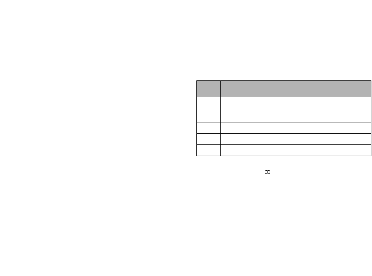
RV-5 Mode Adjust
6-3
PREFERRED LISTENING MODE SELECTION
The INPUT SETUP menus include four preferred listening mode
selection parameters labeled 2-CH, DOLBY D, DTS(-ES), 5.1a and
MIC. These parameters are used to select a preferred listening mode
for 2-channel, Dolby Digital, DTS(-ES), 5.1a and LIVE! input sources.
The RV-5 automatically activates the selected listening mode
whenever a new input is selected or a new input source is present.
MODE AND BUTTONS
The front-panel and remote-control Mode arrow buttons can be
used to audition listening modes with the current Main Zone input
source. Pressing these buttons scrolls up () or down () through
listening modes available for the current Main Zone source.
Listening modes are scrolled in the order that appears in the MODE
ADJUST menu.
For example, if a 2-channel input source is present, press the or
arrow buttons to scroll through available 2-channel listening
modes. The selected listening mode appears in the bottom-left
corner of the Main Zone two-line status.
Dynamic Listening Mode Selection
Dynamic listening modes are only available under certain condi-
tions. For example, many of the dynamic modes are only available
when the RV-5 is configured for seven main output channels and
source material with specific encoding is played. All dynamic
listening modes are available through the remote control or front
panel Mode button.
See “Dynamic Listening Modes” on page 3-13 for a complete
listing of dynamic listening modes.
LISTENING MODE SELECTION BUTTONS
The remote control listening mode selection buttons can be used
to activate the Logic 7 Film, Dolby, DTS(-ES), Logic 7 Music, or
Logic 7 TV listening mode that is appropriate for the Main Zone
input source. For instance, if the L7 button is pressed while a
2-channel source is present, the L7 FILM listening mode is
activated. The table below indicates the listening modes associated
with each mode family selection button.
* These listening mode names differ depending on the input source, the speaker config-
uration and certain parameter settings. For 5.1 systems with only side or rear speak-
ers (but not both), pressing the button loads the DOLBY DIGITAL mode.
** The “MODE SELECTION NOT AVAILABLE” message appears in the on-screen and
front-panel displays when no listening mode is available for the Main Zone input
source that is present.
*** For ES source.
Button 2-Channel
Sources
Dolby Digital
Sources
DTS(-ES)
Sources
5.1a
Sources
L7 F L7 FILM 5.1 L7 FILM DTS(-ES) L7 FILM 5.1a L7 FILM
L7 M L7 MUSIC 5.1 L7 MUSIC DTS(-ES) L7 MUSIC 5.1a L7 MUSIC
L7 TV L7 TV 5.1 L7 TV MODE SELECTION
NOT AVAILABLE**
N/A
L7 MS L7 MUSIC
SURROUND
5.1 L7 MUSIC DTS(-ES) L7 MUSIC N/A
DOLBY DOLBY PLIIx MOV DD 5.1 PLIIx MOV* MODE SELECTION
NOT AVAILABLE**
N/A
DTS DTS NEO:6 CIN MODE SELECTION
NOT AVAILABLE**
DTS(-ES) N/A
Mode Adjust Lexicon
6-4
LISTENING MODE DESCRIPTIONS
Each listening mode description lists the default and possible settings for each listening mode menu parameter. All listening mode menus are
shown in the Appendix. Listening mode menu option and parameter descriptions begin on page 6-30.
L7 FILM
This listening mode is designed for enhanced playback of 2-channel
stereo or matrix-encoded film sources.
Logic 7 FILM is a proprietary Lexicon listening mode that derives
seven channels from 2-channel input sources. Logic 7 also derives
full-frequency stereo surround channels that realistically increase
the perceived width, length and sense of envelopment of the
listening space. Logic 7 provides remarkable improvement
compared to other decoders.
See “Listening Mode Menu Option and Parameter Descriptions” on page 6-30 for
detailed descriptions.
L7 TV
This listening mode is designed for playback of 2-channel stereo or
matrix-encoded television broadcast sources.
Logic 7 TV is a proprietary Lexicon listening mode based on the
Logic 7 FILM listening mode, but specifically tailored for broadcast
sources.
See “Listening Mode Menu Option and Parameter Descriptions” on page 6-30 for
detailed descriptions.
Parameter Default Setting Possible Settings
AUTO AZIMUTH ON ON, OFF
VOCAL ENHANCE +0.0dB +6.0dB, +3.0dB, +0.0dB
RE-EQUALIZER ON ON, OFF
SOUND STAGE REAR FRONT, NEUTRAL, REAR
5 SPKR ENHANCE ON ON, OFF
BASS ENHANCE OFF ON, OFF
SURR ROLLOFF 7.0kHz 500Hz to 20.0kHz, OFF
REAR DLY OFFSET 15ms OFF, 1 to 30ms
OUTPUT LEVELS Refer to page 6-28
CUSTOM Refer to page 6-28
MODE ADJUST FILM
Parameter Default Setting Possible Settings
AUTO AZIMUTH ON ON, OFF
VOCAL ENHANCE +0.0dB +6.0dB, +3.0dB, +0.0dB
FRONT STEERING FILM OFF, MSURR, MUSIC, FILM
RE-EQUALIZER OFF ON, OFF
SOUND STAGE REAR FRONT, NEUTRAL, REAR
5 SPKR ENHANCE ON ON, OFF
BASS ENHANCE OFF ON, OFF
SURR ROLLOFF 7.0kHz 500Hz to 20.0kHz, OFF
REAR DLY OFFSET 15ms OFF, 1 to 30ms
OUTPUT LEVELS Refer to page 6-28
CUSTOM Refer to page 6-28
MODE ADJUST TV
RV-5 Mode Adjust
6-5
L7 MUSIC
This listening mode is designed for playback of 2-channel stereo or
matrix-encoded music sources.
Logic 7 MUSIC is a proprietary Lexicon listening mode based on the
Logic 7 FILM listening mode, but specifically tailored for music
sources.
See “Listening Mode Menu Option and Parameter Descriptions” on page 6-30 for
detailed descriptions.
L7 MUSIC SURR
This listening mode is designed for playback of 2-channel stereo
music sources recorded in real spaces and for playback of
recordings that contain added reverb. It is recommended for
classical music sources, which are often recorded in real spaces with
added reverb to enhance the stereo mix.
Logic 7 MUSIC SURR is a proprietary Lexicon listening mode that is
similar to the MUSIC SURROUND listening mode in other Lexicon
products. Logic 7 extracts ambient sounds from the input source
and sends these sounds to all speakers. Ambient sounds are heard
from all directions, creating a realistic playback presentation that
simulates what listeners experience in real spaces.
See “Listening Mode Menu Option and Parameter Descriptions” on page 6-30 for
detailed descriptions.
Parameter Default Setting Possible Settings
VOCAL ENHANCE +0.0dB +6.0dB, +3.0dB, +0.0dB
FRONT STEERING MUSIC OFF, MSURR, MUSIC, FILM
SOUND STAGE NEUTRAL FRONT, NEUTRAL, REAR
5 SPKR ENHANCE ON ON, OFF
BASS ENHANCE OFF ON, OFF
SURR ROLLOFF 7.0kHz 500Hz to 20.0kHz, OFF
REAR DLY OFFSET 15ms OFF, 1 to 30ms
OUTPUT LEVELS Refer to page 6-28
CUSTOM Refer to page 6-28
MODE ADJUST MUSIC
Parameter Default Setting Possible Settings
VOCAL ENHANCE +0.0dB +6.0dB, +3.0dB, +0.0dB
FRONT STEERING MSURR OFF, MSURR, MUSIC, FILM
SOUND STAGE NEUTRAL FRONT, NEUTRAL, REAR
5 SPKR ENHANCE ON ON, OFF
BASS ENHANCE OFF ON, OFF
SURR ROLLOFF 7.0kHz 500Hz to 20.0kHz, OFF
REAR DLY OFFSET 15ms OFF, 1 to 30ms
OUTPUT LEVELS Refer to page 6-28
CUSTOM Refer to page 6-28
MODE ADJUST MUSIC SURR
Mode Adjust Lexicon
6-6
DOLBY PLIIx MOV & DOLBY PLII MOVIE
Dolby Pro Logic IIx technology is an extension to Dolby Pro Logic II
that enables the listener to experience natural and seamless 6.1- or
7.1-channel (six or seven speakers and a subwoofer) surround sound
from any native two-channel (stereo) or 5.1-channel source.
Dolby PLIIx MOV and Dolby PLII MOVIE modes:
• Are designed for playback of Dolby Surround-encoded sources.
• Provide impressive enhancement compared to Dolby Pro Logic
decoding.
• Are appropriate for Dolby Surround-encoded film sources.
The PLIIx listening mode is only available when the front, side and rear
speakers are present.
Activating the DOLBY PLIIx MOV listening mode
The DOLBY PLIIx MOV listening mode is a dynamic listening mode
and cannot be assigned as a preferred listening mode for 2-channel
Dolby Surround-encoded film sources. To activate the DOLBY PLIIx
Mov listening mode, play the 2-channel source input, and select the
DOLBY PLIIx MOV listening mode using the front-panel or remote
control Mode buttons.
When the 2-CH parameter is set to USE LAST, the RV-5 will automat-
ically activate the DOLBY PLIIx MOV listening mode if this listening
mode was activated the last time a 2-channel Dolby Surround-
encoded film source was present.
Note:
The PLIIx MOV mode does not appear in the list of available listening modes
if either the side or rear speakers are missing from the configuration.
See “Listening Mode Menu Option and Parameter Descriptions” on page 6-30 for
detailed descriptions.
MODE ADJUST PLIIx MOVIE MODE ADJUST PLII MOVIE
OR
Parameter
OUTPUT LEVELS Refer to page 6-28
CUSTOM Refer to page 6-28
RV-5 Mode Adjust
6-7
DOLBY PLIIx MUS & DOLBY PLII MUSIC
Dolby Pro Logic IIx technology is an extension to Dolby Pro Logic II
that enables the listener to experience natural and seamless 6.1- or
7.1-channel (six or seven speakers and a subwoofer) surround sound
from any native two-channel (stereo) or 5.1-channel source.
The PLIIx listening mode is only available when the front, side and rear
speakers are present.
Activating the DOLBY PLIIx MUS listening mode
The DOLBY PLIIx MUS listening mode is a dynamic listening mode and
cannot be assigned as a preferred listening mode for 2-channel Dolby
Surround-encoded film sources. To activate the DOLBY PLIIx MUS
listening mode, play the 2-channel source input, and select the DOLBY
PLIIx MUS listening mode using the front-panel or remote control
Mode buttons.
When the 2-CH parameter is set to USE LAST, the RV-5 will automat-
ically activate the DOLBY PLIIx MUS listening mode if this listening
mode was activated the last time a 2-channel Dolby Surround-
encoded film source was present.
Note:
The DOLBY PLIIx MUS mode does not appear in the list of available listening
modes if either the side or rear speakers are missing from the configuration.
See “Listening Mode Menu Option and Parameter Descriptions” on page 6-30 for
detailed descriptions.
MODE ADJUST PLIIx MUS MODE ADJUST PLII MUSIC
OR
Parameter Default Setting Possible Settings
PANORAMA OFF ON, OFF
CTR WIDTH 3 MIN, 1 to 6, MAX
DIMENSION NEUTRAL FRONT, NEUTRAL, REAR
SURROUND DLY 10ms 0 to 15ms
OUTPUT LEVELS Refer to page 6-28
CUSTOM Refer to page 6-28
Mode Adjust Lexicon
6-8
DOLBY PRO LOGIC
The Dolby PRO LOGIC mode is designed for playback of Dolby
Surround-encoded sources. It decodes four channels from Dolby
Surround-encoded sources, and uses a mono surround channel
with a high-frequency rolloff above 7kHz.
This mode is useful for comparison purposes, particularly with the
L7 FILM, Dolby PLIIx MOVIE and DTS Neo:6 CIN listening mode.
See “Listening Mode Menu Option and Parameter Descriptions” on page 6-30 for
detailed descriptions.
DTS NEO:6 CIN & DTS NEO:6 MUSIC
These modes are designed for playback of matrix-encoded digital
stereo film or music sources. DTS Neo:6 derives six channels when
both side and rear speakers are present (rear channels will be in
parallel). It derives five channels when only side or rear speakers are
present.
These listening modes are dynamic listening modes and cannot be
assigned as preferred listening modes. To select either of these
listening modes, use the remote control or front-panel Mode
button. When the 2-CH parameter is set to USE LAST, the RV-5 will
automatically activate a DTS Neo:6 listening mode if this mode was
activated the last time a 2-channel source was present.
Note:
• The RV-5 will not automatically activate a DTS NEO:6 listening
mode unless a 44.1kHz or 48kHz PCM digital source is present.
The DTS Neo:6 listening modes are not available with 88.2kHz or
96kHz, Dolby Digital or analog sources.
• The DTS Neo:6 MUSIC listening mode can be activated with the
front-panel or remote control Mode buttons. The DTS Neo:6 CIN
listening mode can also activated with the remote control DTS
button when a 2-channel input source is present.
See “Listening Mode Menu Option and Parameter Descriptions” on page 6-30 for
detailed descriptions.
Parameter
OUTPUT LEVELS Refer to page 6-28
CUSTOM Refer to page 6-28
MODE ADJUST PRO LOGIC
Parameter
OUTPUT LEVELS Refer to page 6-28
CUSTOM Refer to page 6-28
MODE ADJUST CIN MUSIC
OR
RV-5 Mode Adjust
6-9
NIGHTCLUB
The NIGHTCLUB mode is designed for playback of “dry” music
sources that benefit from the addition of room reflections,
especially music sources that lack ambience in the recording. The
NIGHTCLUB mode generates early reflections and sends them to
the front, side and rear channels to simulate small, intimate
listening spaces.
The NIGHTCLUB mode is a superior room simulation listening
mode because it uses a proprietary reverb algorithm inherited from
Lexicon professional products.
See “Listening Mode Menu Option and Parameter Descriptions” on page 6-30 for
detailed descriptions.
CONCERT HALL
The CONCERT HALL mode generates early reflections and sends
them to the front, side and rear channels to simulate large listening
spaces.
The CONCERT HALL mode is a superior room simulation listening
mode because it uses a proprietary reverb algorithm inherited from
Lexicon professional products.
See “Listening Mode Menu Option and Parameter Descriptions” on page 6-30 for
detailed descriptions.
Parameter Default Setting Possible Settings
CENTER DEPTH 11 0 to 18
SPEECH DETECT ON ON, OFF
SIZE 5m 4 to 20m
LIVENESS 196ms 30ms to 20.2s
PRE-DELAY 5ms OFF, 1 to 100ms
ROLLOFF 9.0kHz 500Hz to 20.0kHz, OFF
EFFECT LVL +3dB –12 to +6dB
OUTPUT LEVELS Refer to page 6-28
CUSTOM Refer to page 6-28
MODE ADJUST NIGHTCLUB
Parameter Default Setting Possible Settings
CENTER DEPTH 12 0 to 18
SPEECH DETECT ON ON, OFF
SIZE 20m 4 to 20m
LIVENESS 1.72s 30ms to 20.2s
PRE-DELAY OFF OFF, 1 to 100ms
ROLLOFF 2.4kHz 500Hz to 20.0kHz, OFF
EFFECT LVL –2dB –12 to +6dB
OUTPUT LEVELS Refer to page 6-28
CUSTOM Refer to page 6-28
MODE ADJUST CONCERT HALL
Mode Adjust Lexicon
6-10
CHURCH
The CHURCH mode uses a reverb algorithm to emphasize the rich,
smooth, reverberant decay characteristic of small and medium
listening spaces – such as churches and chambers – with long rever-
beration time relative to their sizes.
The CHURCH mode is a superior room simulation listening mode
because it uses a proprietary reverb algorithm inherited from
Lexicon professional products.
* BASS RT, MID RT and SIZE parameter settings are interdependent, meaning that the full
parameter range might not be available depending on the other parameter settings.
See “Listening Mode Menu Option and Parameter Descriptions” on page 6-30 for
detailed descriptions.
CATHEDRAL
The CATHEDRAL mode is similar to the CHURCH listening mode. It
uses a reverb algorithm to emphasize the rich, smooth, reverberant
decay characteristic of large listening spaces – such as cathedrals –
with long reverberation time relative to their size.
The CATHEDRAL mode is a superior room simulation listening
mode because it uses a proprietary reverb algorithm inherited from
Lexicon professional products.
* BASS RT, MID RT and SIZE parameter settings are interdependent, meaning that the full
parameter range might not be available depending on the other parameter settings.
See “Listening Mode Menu Option and Parameter Descriptions” on page 6-30 for
detailed descriptions.
Parameter Default Setting Possible Settings
CENTER DEPTH 5 0 to 18
SPEECH DETECT ON ON, OFF
SIZE* 20m 4 to 30m
MID RT* 1.56s 24ms to 24.3s
BASS RT* 1.87s 5ms to 48.6s
PRE-DELAY 24ms OFF, 1 to 100ms
ROLLOFF 2.4kHz 500Hz to 20.0kHz, OFF
EFFECT LVL –3dB –12 to +6dB
OUTPUT LEVELS Refer to page 6-28
CUSTOM Refer to page 6-28
MODE ADJUST CHURCH
Parameter Default Setting Possible Settings
CENTER DEPTH 12 0 to 18
SPEECH DETECT ON ON, OFF
SIZE* 30m 4 to 30m
MID RT* 3.72s 24ms to 24.3s
BASS RT* 4.47s 5ms to 48.6s
PRE-DELAY 23ms OFF, 1 to 100ms
ROLLOFF 3.1kHz 500Hz to 20.0kHz, OFF
EFFECT LVL –8dB –12 to +6dB
OUTPUT LEVELS Refer to page 6-28
CUSTOM Refer to page 6-28
MODE ADJUST CATHEDRAL
RV-5 Mode Adjust
6-11
PANORAMA
The PANORAMA mode is designed for playback of stereo and
matrix-encoded sources. PANORAMA uses proprietary Lexicon
algorithms to move the stereo image outward from the front
speakers, producing a wider stereo field with greater depth.
Sound quality depends on proper location of the listening position
and front speakers. When the front speakers are positioned close to
either side of the display device, the effect is produced over a wider
area than when the front speakers are positioned at a large angle
from the display device.
See “Listening Mode Menu Option and Parameter Descriptions” on page 6-30 for
detailed descriptions.
PANORAMA CALIBRATION
Select PANORAMA CALIBRATION to open
the PANORAMA CALIBRATION menu shown
to the left, to calibrate the PANORAMA
listening mode. This listening mode must be
calibrated to take full advantage of its
effects.
For best results, you should center the
primary listening position between the front
left and right speakers as shown in the Center illustration at the top
of the next page. Otherwise, the PANORAMA listening mode will be
calibrated with varying results.
An external calibration source is required to calibrate the
PANORAMA listening mode. You should select a familiar stereo
source.
See “Listening Mode Menu Option and Parameter Descriptions” on page 6-30 for
detailed descriptions.
Parameter Default Setting Possible Settings
EFFECT LVL +4dB –12 to +6dB
BASS CONTENT STEREO BINAURL, MONO, STEREO
LOW FREQ WIDTH +0 –25 to +25dB
SURR ROLLOFF 3.1kHz 500Hz to 20.0kHz, OFF
REAR DLY OFFSET 15ms OFF, 1 to 30ms
INPUT BALANCE <|> L< to <|> to >R
CALIBRATION Refer to next column
OUTPUT LEVELS Refer to page 6-28
CUSTOM Refer to page 6-28
MODE ADJUST PANORAMA
Parameter Default Setting Possible Settings
SOURCE LEFT & RIGHT RIGHT, LEFT & RIGHT, LEFT
SPEAKER ANGLE 30deg 10 to 90deg
LISTENER POS +0 -127 to +127
MODE ADJUST PANORAMA CALIBRATION
PANORAMA CALIBRATION
SOURCE
SPEAKER ANGLE
LISTENER POS
NOTE:
ENSURE THAT
“SPEAKER SETUP” HAS
BEEN PROPERLY
PERFORMED
LEFT & RIGHT
30deg
+0
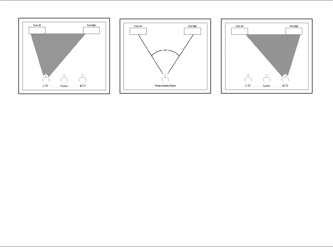
Mode Adjust Lexicon
6-12
To calibrate the PANORAMA listening mode:
1. Remove all obstructions between the speakers and the primary
listening position.
2. Make sure the distances between the speakers and the primary
listening position are properly measured. To do this, select one
of the following options.
• Select the AUTO SPEAKER SETUP menu DISTANCES option to
have the RV-5 automatically calibrate speaker distances.
• Measure the distance between the primary listening posi-
tion and the front baffle of each speaker. Then, set the cor-
responding SPEAKER DISTANCES menu parameters to the
closest available value.
3. Sit in the primary listening position. If the primary listening
position is not centered between the front left and right
speakers as shown in illustration B (above), set the PANORAMA
CALIBRATION LISTENER POS parameter to compensate for
the difference using the remote control and arrow
buttons. Each increment within the –127 to +127 parameter
range represents about one-third of an inch. The Left illus-
tration shows the left-of-center position. The Right illustration
shows the right- of-center position
4. Set the SOURCE parameter to RIGHT.
5. Begin playback of the external calibration source.
6. When playback of the external calibration source is in progress,
set the SPEAKER ANGLE parameter so the sound is not heard in
the right ear.
7. To confirm the LISTENER POS and SPEAKER ANGLE parameter
settings, set the SOURCE parameter to LEFT & RIGHT. If the
PANORAMA listening mode is properly calibrated, the sound
should be perceived to come from all around the primary
listening position. If not, go back to Step 1 and repeat the
calibration procedure.
LEFT RIGHTCENTER
RV-5 Mode Adjust
6-13
2-CH SURROUND
This mode, designed for playback of stereo sources, sends the left
channel to Front, Side and Rear Left channels and the right channel
to Front, Side and Rear Right channels, and sums the Left and Right
for the center. It is recommended for background music.
2-CHANNEL
This mode, designed for playback of stereo sources, sends the left and
right channels to the Front L/R and Subwoofer channels. It is recom-
mended for two-speaker playback with subwoofers and for
comparison purposes with other listening modes.
See “Listening Mode Menu Option and Parameter Descriptions” on page 6-30 for
detailed descriptions.
MONO LOGIC
This mode, designed for playback of mono sources, uses proprietary
Lexicon reverb algorithms to realistically expand mono sources to
use all channels. This dramatically increases the perceived width
and sense of envelopment of the listening space.
See “Listening Mode Menu Option and Parameter Descriptions” on page 6-30 for
detailed descriptions.
Parameter
OUTPUT LEVELS Refer to page 6-28
CUSTOM Refer to page 6-28
Parameter Default Setting Possible Settings
SUB LEVEL +0dB OFF, –30 to +12dB
CUSTOM Refer to page 6-28
MODE ADJUST 2-CH SURROUND
MODE ADJUST 2-CHANNEL
Parameter Default Setting Possible Settings
EFFECT LVL –9dB –12 to +6dB
ACADEMY FILTER ON ON, OFF
SURR ROLLOFF 3.1kHz 500Hz to 20.0kHz, OFF
OUTPUT LEVELS Refer to page 6-28
CUSTOM Refer to page 6-28
MODE ADJUST MONO LOGIC
Mode Adjust Lexicon
6-14
MONO SURROUND
This mode, designed for playback of mono sources, sends the
mono source to all channels.
MONO
This mode, designed for playback of mono sources, sends mono
sources to the center channel and subwoofer.
See “Listening Mode Menu Option and Parameter Descriptions” on page 6-30 for
detailed descriptions.
5.1 L7 FILM
The 5.1 L7 FILM mode is a proprietary Lexicon listening mode
designed for playback of 5.1-channel Dolby Digital-encoded film
sources, and provides remarkable improvement compared to other
decoders.
It derives seven channels from 5.1-channel input sources with
enhanced front steering. When both side and rear speakers are
present, the 5.1 L7 FILM listening mode also increases the perceived
length and sense of envelopment of the listening space.
See “Listening Mode Menu Option and Parameter Descriptions” on page 6-30 for
detailed descriptions.
Parameter
OUTPUT LEVELS Refer to page 6-28
CUSTOM Refer to page 6-28
Parameter Default Setting Possible Settings
SUB LEVEL +0dB OFF, –30 to +12dB
CUSTOM Refer to page 6-28
MODE ADJUST
MONO SURROUND
MODE ADJUST MONO
Parameter Default Setting Possible Settings
VOCAL ENHANCE +0.0dB +6.0dB, +3.0dB, +0.0dB
RE-EQUALIZER ON ON, OFF
SOUND STAGE REAR REAR, NEUTRAL, FRONT
5 SPKR ENHANCE ON ON, OFF
BASS ENHANCE OFF ON, OFF
SURR ROLLOFF 7kHz 500HZ to 20kHz, OFF
REAR DLY OFFSET 15ms OFF, 1ms to 30ms
COMPRESSION OFF AUTO, ON, OFF
LFE MIX +0.0dB –10.0dB to +0.0dB
OUTPUT LEVELS Refer to page 6-28
CUSTOM Refer to page 6-28
MODE ADJUST 5.1 FILM
RV-5 Mode Adjust
6-15
5.1 L7 TV
This proprietary Lexicon listening mode is designed for playback of
5.1-channel Dolby Digital-encoded broadcast sources. Based on the
5.1 L7 FILM listening mode, 5.1 L7 TV derives seven channels from
5.1-channel input sources with enhanced front steering.
See “Listening Mode Menu Option and Parameter Descriptions” on page 6-30 for
detailed descriptions.
5.1 L7 MUSIC
This proprietary Lexicon listening mode is designed for playback of
5.1-channel Dolby Digital-encoded music sources. Based on the 5.1
L7 FILM listening mode, 5.1 L7 MUSIC derives seven channels from
5.1-channel input sources with enhanced front steering.
See “Listening Mode Menu Option and Parameter Descriptions” on page 6-30 for
detailed descriptions.
Parameter Default Setting Possible Settings
VOCAL ENHANCE +0.0dB +6.0dB, +3.0dB, +0.0dB
FRONT STEERING FILM OFF, MSURR, MUSIC, FILM
RE-EQUALIZER OFF ON, OFF
SOUND STAGE REAR REAR, NEUTRAL, FRONT
5 SPKR ENHANCE ON ON, OFF
BASS ENHANCE OFF ON, OFF
SURR ROLLOFF 7kHz 500HZ to 20kHz, OFF
REAR DLY OFFSET 15ms OFF, 1ms to 30ms
COMPRESSION OFF AUTO, ON, OFF
LFE MIX +0.0dB –10.0dB to +0.0dB
OUTPUT LEVELS Refer to page 6-28
CUSTOM Refer to page 6-28
MODE ADJUST 5.1 TV
Parameter Default Setting Possible Settings
VOCAL ENHANCE +0.0dB +6.0dB, +3.0dB, +0.0dB
FRONT STEERING MUSIC OFF, MSURR, MUSIC, FILM
RE-EQUALIZER OFF ON, OFF
SOUND STAGE NEUTRAL REAR, NEUTRAL, FRONT
5 SPKR ENHANCE ON ON, OFF
BASS ENHANCE OFF ON, OFF
SURR ROLLOFF 7kHz 500HZ to 20kHz, OFF
REAR DLY OFFSET 15ms OFF, 1ms to 30ms
COMPRESSION OFF AUTO, ON, OFF
LFE MIX +0.0dB –10.0dB to +0.0dB
OUTPUT LEVELS Refer to page 6-28
CUSTOM Refer to page 6-28
MODE ADJUST 5.1 MUSIC

Mode Adjust Lexicon
6-16
5.1 PLIIx MOV
The 5.1 PLIIx MOV (MOVIE) listening mode is designed to play back
7.1 discrete channels decoded from 5.1-channel Dolby Digital film
sources. The seven main channels are full-frequency. The .1 channel,
often referred to as LFE information, has a limited frequency range of
up to 120Hz.
The 5.1 PLIIx MOV listening mode is only available when the front, side
and rear speakers are present.
Note:
The RV-5RV-5 cannot detect Dolby Digital Surround EX encoding in
non-flagged 5.1-channel Dolby Digital input sources.
Activating the 5.1 PLIIx MOV listening mode
The 5.1 PLIIx MOV listening mode is a dynamic listening mode and
cannot be assigned as a preferred listening mode for Dolby Digital film
sources. To activate this listening mode, use the front-panel or remote
control Mode buttons.
When the DOLBY D parameter is set to USE LAST, the RV-5 will
automatically activate the dynamic 5.1 PLIIx MOV listening mode if
this listening mode was activated the last time a Dolby Digital
source was present.
Note:
The 5.1 PLIIx MOV mode will not appear in the list of available listening
modes if either the side or rear speakers are missing from the
configuration.
See “Listening Mode Menu Option and Parameter Descriptions” on page 6-30 for
detailed descriptions.
MODE ADJUST 5.1 PLIIx MOV
Parameter Default Setting Possible Settings
EX DECODING AUTO AUTO, ON, OFF
COMPRESSION OFF AUTO, ON, OFF
LFE MIX +0.0dB –10.0 to +0.0dB
OUTPUT LEVELS Refer to page 6-28
CUSTOM Refer to page 6-28

RV-5 Mode Adjust
6-17
5.1 PLIIx MUS
The 5.1 PLIIx MUS (MUSIC) listening mode is designed to playback 7.1
discrete channels decoded from 5.1-channel Dolby Digital music
sources. The seven main channels are full–frequency. The .1 channel,
often referred to as LFE information, has a limited frequency range of
up to 120Hz.
Note:
The RV-5 cannot detect Dolby Digital Surround EX encoding in
non-flagged 5.1-channel Dolby Digital input sources.
Activating the 5.1 PLIIx MUS listening mode
The 5.1 PLIIx MUS listening mode is a dynamic listening mode and
cannot be assigned as a preferred listening mode for Dolby Digital
sources. To activate this listening mode, use the front-panel or remote
control Mode buttons.
When the DOLBY D parameter is set to USE LAST, the RV-5 will
automatically activate the dynamic 5.1 PLIIx MUS listening mode if
this listening mode was activated the last time a Dolby Digital
source was present.
Note:
The 5.1 PLIIx MUS mode does not appear in the list of available listening
modes if either the side or rear speakers are missing from the configuration.
See “Listening Mode Menu Option and Parameter Descriptions” on page 6-30 for
detailed descriptions.
MODE ADJUST 5.1 PLIIx MUS
Parameter Default Setting Possible Settings
EX DECODING AUTO AUTO, ON, OFF
COMPRESSION OFF AUTO, ON, OFF
LFE MIX +0.0dB –10.0 to +0.0dB
OUTPUT LEVELS Refer to page 6-28
CUSTOM Refer to page 6-28
Mode Adjust Lexicon
6-18
DOLBY DIGITAL & DOLBY DIGITAL EX
These listening modes are designed to decode and play back 5.1
discrete channels from 5.1-channel Dolby Digital sources. The five
main channels are full-frequency. The .1 channel, often referred to
as LFE information, has a limited frequency range of 120Hz.
The mode name differs, depending on the encoding present in the
input source, the EX DECODING parameter setting and the speaker
setup.
The Dolby DIGITAL EX listening mode is recommended for Dolby
Digital sources recorded with Dolby Digital Surround EX
encoding. This listening mode can also be used with other types
of 5.1-channel Dolby Digital sources with mixed results. The table
at the bottom of the page shows the conditions for the behavior
of the Dolby Digital EX mode when activated.
The Dolby DIGITAL EX listening mode is available when both the
side and rear speakers are present and Dolby Digital Surround EX
decoding is activated. Matrix decoding is then applied to derive a
surround back channel from the other surround channels.
• Dolby Digital Surround EX decoding is activated when the EX
DECODING parameter is set to ON or AUTO and a flagged
5.1-channel Dolby Digital source recorded with Dolby Digital
Surround EX encoding is detected.
• Dolby Digital Surround EX decoding is not activated when the
EX DECODING parameter is set to OFF or AUTO and a non-
flagged 5.1-channel Dolby Digital source recorded with or
without Dolby Digital Surround EX encoding is detected.
Note:
The RV-5 cannot detect Dolby Digital Surround EX encoding in non-
flagged 5.1-channel Dolby Digital input sources because they do not
include information in the input signal that identifies Dolby Digital
Surround EX encoding.
MODE ADJUST OR DIGITAL EXDIGITAL
Parameter Default Setting Possible Settings
EX DECODING AUTO AUTO, ON, OFF
COMPRESSION OFF AUTO, ON, OFF
LFE MIX +0.0dB –10.0 to +0.0dB
OUTPUT LEVELS Refer to page 6-28
CUSTOM Refer to page 6-28
Input Source
Parameter Setting 5.1-Channel Dolby Digital 5.1-Channel Surround EX
(Flagged)
5.1-Channel Surround EX
(Non-Flagged)
EX DECODING: AUTO DOLBY DIGITAL DOLBY DIGITAL EX DOLBY DIGITAL
EX DECODING: ON DOLBY DIGITAL EX DOLBY DIGITAL EX DOLBY DIGITAL EX
EX DECODING: OFF DOLBY DIGITAL DOLBY DIGITAL DOLBY DIGITAL
RV-5 Mode Adjust
6-19
5.1 2-CHANNEL
This mode, recommended for recording purposes, is designed for
converting 5.1-channel Dolby Digital-encoded input sources into
2-channel Logic 7-encoded output signals.
The downmixed 5.1-channel Dolby Digital input signals are sent to
the Front L/R speakers and subwoofer.
See “Listening Mode Menu Option and Parameter Descriptions” on page 6-30 for
detailed descriptions.
5.1 MONO LOGIC
This listening mode, designed for playback of Dolby Digital-encoded
mono sources, uses proprietary Lexicon reverb algorithms to realisti-
cally expand mono sources to use all channels. This dramatically
increases the perceived width and sense of envelopment of the
listening space.
Note that:
When a 1.0 Dolby Digital source is present, the RV-5 automatically
activates the 5.1 MONO LOGIC listening mode.
See “Listening Mode Menu Option and Parameter Descriptions” on page 6-30 for
detailed descriptions.
Parameter Default Setting Possible Settings
CENTER MIX +0dB –25 to +5dB
SURROUND MIX +0dB –5 to +5dB
CNTR DLY SAMPLES +0 –127 to +127
MASTER LEVEL +0dB –5 to +5dB
COMPRESSION OFF AUTO, ON, OFF
LFE MIX +0.0dB –20.0 to +0.0dB
SUB LEVEL +0dB OFF, -30 to +12dB
CUSTOM Refer to page 6-28
5.1 2-CHANNEL
MODE ADJUST
Parameter Default Setting Possible Settings
EFFECT LVL –9dB –12 to +6dB
ACADEMY FILTER ON ON, OFF
SURR ROLLOFF 3.1kHz 500Hz to 20.0kHz, OFF
OUTPUT LEVELS Refer to page 6-28
CUSTOM Refer to page 6-28
5.1 MONO LOGIC
MODE ADJUST
Mode Adjust Lexicon
6-20
5.1 MONO SURR
This listening mode, designed for playback of Dolby Digital-encoded
mono sources, sends mono signals to all channels.
See “Listening Mode Menu Option and Parameter Descriptions” on page 6-30 for
detailed descriptions.
5.1 MONO
This listening mode, designed for playback of Dolby Digital-encoded
mono sources, sends mono signals to the center channel and
subwoofer.
See “Listening Mode Menu Option and Parameter Descriptions” on page 6-30 for
detailed descriptions.
Parameter
OUTPUT LEVELS Refer to page 6-28
CUSTOM Refer to page 6-28
5.1 MONO SURR
MODE ADJUST
Parameter Default Setting Possible Settings
SUB LEVEL +0dB OFF, –30 to +12dB
CUSTOM Refer to page 6-28
5.1 MONO
MODE ADJUST
RV-5 Mode Adjust
6-21
DTS-ES DECODING
The DTS, DTS-ES, and DTS-ES Discr listening modes are designed
for, at a minimum, playback of 5.1-channel DTS, 5.1-channel
matrix-encoded DTS-ES and 6.1-channel discrete-encoded DTS-ES
sources.
The DTS, DTS-ES, and DTS-ES Discr listening mode names differ
depending on the encoding present in the input source, the
DECODING parameter setting and the speaker setup.
DTS-ES listening modes are available when DTS-ES decoding is
activated. The table at the bottom of the page shows the conditions
for the behavior of DTS-ES decoding when it is activated.
• DTS-ES decoding is activated when both the side and rear
speakers are present and the ES DECODING parameter is set to
ON or AUTO and a 5.1-channel matrix-encoded or a
6.1-channel discrete-encoded DTS-ES source is detected.
• DTS-ES decoding is deactivated when the ES DECODING
parameter is set to OFF or when the ES DECODING parameter
is set to AUTO and a 5.1-channel DTS source is detected.
• DTS-ES Discr mode decodes 6.1-channel discrete-encoded
DTS-ES sources when ES decoding is set to AUTO or ON in the
MODE ADJUST menu. The mode appears in the Setup menu
when a DTS 6.1 source is present and seven speakers are
selected in the SPEAKER SETUP menu.
Note:
The table below is not applicable to the DTS-ES THX, DTS THX ULTRA2
and DTS THX MUSIC listening modes. These listening modes will be
explained in greater detail later in this manual.
Input Source
Parameter Setting 5.1-Channel DTS 5.1-Channel
Matrix-Encoded DTS-ES
6.1-Channel
Discrete-Encoded DTS-ES
ES DECODING: AUTO DTS DTS-ES DTS-ES
ES DECODING: ON DTS-ES DTS-ES DTS-ES
ES DECODING: OFF DTS DTS DTS
Mode Adjust Lexicon
6-22
DTS-ES L7 FILM & DTS L7 FILM
These proprietary Lexicon listening modes use an advanced matrix to
decode seven channels from 5.1- and 6.1-channel film sources with
enhanced front steering. When both side and rear speakers are
present, the DTS-ES L7 FILM listening mode also increases the
perceived length and sense of envelopment of the listening space.
The listening modes are designed for enhanced playback of 5.1-channel
DTS, 5.1-channel matrix-encoded DTS-ES, or 6.1-channel discrete-
encoded DTS-ES film sources. The listening mode name differs,
depending on the encoding present in the input source, the ES
DECODING parameter setting and the speaker setup.
See “Listening Mode Menu Option and Parameter Descriptions” on page 6-30 for
detailed descriptions.
DTS-ES L7 MUSIC & DTS L7 MUSIC
These proprietary Lexicon listening modes, similar to the DTS-ES
L7 FILM listening mode, use an advanced matrix to decode seven
channels from 5.1 and 6.1-channel music sources with
enhanced front steering to provide remarkable sound
improvement compared to other decoders.
The listening modes are designed for enhanced playback of
5.1-channel DTS, 5.1-channel matrix-encoded DTS-ES, or
6.1-channel discrete-encoded DTS-ES music sources. The
listening mode name differs, depending on the encoding
present in the input source, the ES DECODING parameter
setting and the speaker setups.
See “Listening Mode Menu Option and Parameter Descriptions” on page 6-30 for
detailed descriptions.
Option/Parameter Default Setting Possible Settings
VOCAL ENHANCE +0.0dB +6.0dB, +3.0dB, +0.0dB
RE-EQUALIZER ON ON, OFF
SOUND STAGE REAR REAR, NEUTRAL, FRONT
5 SPKR ENHANCE ON ON, OFF
BASS ENHANCE OFF ON, OFF
SURR ROLLOFF 7kHz 500Hz to 20kHz, OFF
REAR DLY OFFSET 15ms OFF, 1 to 30ms
LFE MIX +0.0dB -10.0 to +0.0dB
ES DECODING AUTO AUTO, ON, OFF
OUTPUT LEVELS Refer to page 6-28
CUSTOM Refer to page 6-28
FILM
MODE ADJUST FILM
OR
Option/Parameter Default Setting Possible Settings
VOCAL ENHANCE +0.0dB +6.0dB, +3.0dB, +0.0dB
FRONT STEERING MUSIC OFF, MSURR, MUSIC, FILM
RE-EQUALIZER OFF ON, OFF
SOUND STAGE NEUTRAL REAR, NEUTRAL, FRONT
5 SPKR ENHANCE ON ON, OFF
BASS ENHANCE OFF ON, OFF
SURR ROLLOFF 7kHz 500Hz to 20kHz, OFF
REAR DLY OFFSET 15ms OFF, 1 to 30ms
LFE MIX +0.0dB –10.0 to +0.0dB
ES DECODING AUTO AUTO, ON, OFF
OUTPUT LEVELS Refer to page 6-28
CUSTOM Refer to page 6-28
MUSIC
MODE ADJUST OR MUSIC
RV-5 Mode Adjust
6-23
DTS, DTS-ES & DTS(-ES) Discr
This mode decodes 5.1 matrix or 6.1 discrete channels from DTS-ES
sources. It is designed for playback of 5.1-channel DTS, 5.1-channel
matrix-encoded DTS-ES, and 6.1-channel discrete-encoded DTS-ES
sources.
The six decoded main channels are full-frequency. The .1 channel,
often referred to as LFE information, has a limited frequency range
of 120Hz.
The listening mode name differs, depending on the encoding
present in the input source, the DECODING parameter setting, and
the speaker setup. Refer to page 6-21 for more information.
See “Listening Mode Menu Option and Parameter Descriptions” on page 6-30 for
detailed descriptions.
DTS 2-CHAN & DTS-ES 2-CHAN
These modes, recommended for recording purposes, send
downmixed 5.1-channel or 6.1-channel DTS-ES input signals to the
front speakers and subwoofer as 2-channel Logic 7-encoded output
signals.
See “Listening Mode Menu Option and Parameter Descriptions” on page 6-30 for
detailed descriptions.
Option/Parameter Default Setting Possible Settings
LFE MIX +0.0dB –10.0 to +0.0dB
ES DECODING AUTO AUTO, ON, OFF
OUTPUT LEVELS Refer to page 6-28
CUSTOM Refer to page 6-28
MODE ADJUST OR Discr
OR
Option/Parameter Default Setting Possible Settings
CENTER MIX +0dB –25 to +5dB
SURROUND MIX +0dB –5 to +5dB
CNTR DLY SAMPLES +0 –127 to +127
MASTER LEVEL +0dB –5 to +5dB
LFE MIX +0.0dB –20.0 to +0.0dB
ES DECODING AUTO AUTO, ON, OFF
SUB LEVEL +0dB OFF, –30 to +12dB
CUSTOM Refer to page 6-28
2-CHAN
MODE ADJUST OR
2-CHAN
Mode Adjust Lexicon
6-24
5.1a L7 FILM
The 5.1a LOGIC7 FILM listening mode is a proprietary Lexicon lis-
tening mode that uses LOGIC7 decoding to derive seven channels
from 5.1-channel analog film sources with enhanced front steering.
This listening mode allows 5.1-channel analog sources to use bass
management, speaker crossovers, speaker distance calibration, and
audio controls (tone controls).
See “Listening Mode Menu Option and Parameter Descriptions” on page 6-30 for
detailed descriptions.
5.1a L7 MUSIC
The 5.1a LOGIC7 MUSIC listening mode is similar to the 5.1a
LOGIC7 FILM listening mode, but specifically tailored for music
sources. This mode is designed and recommended for playback of
5.1-channel analog music sources.
See “Listening Mode Menu Option and Parameter Descriptions” on page 6-30 for
detailed descriptions.
Option/Parameter Default Setting Possible Settings
VOCAL ENHANCE +0.0dB +6.0dB, +3.0dB, +0.0dB
RE-EQUALIZER ON ON, OFF
SOUND STAGE REAR REAR, NEUTRAL, FRONT
5 SPKR ENHANCE ON ON, OFF
BASS ENHANCE OFF ON, OFF
SURR ROLLOFF 7kHz 500Hz to 20kHz, OFF
REAR DLY OFFSET 15ms OFF, 1 to 30ms
LFE MIX +0.0dB -10.0 to +0.0dB
OUTPUT LEVELS Refer to page 6-28
CUSTOM Refer to page 6-28
MODE ADJUST 5.1 FILM
Option/Parameter Default Setting Possible Settings
VOCAL ENHANCE +0.0dB +6.0dB, +3.0dB, +0.0dB
FRONT STEERING MUSIC OFF, MSURR, MUSIC, FILM
RE-EQUALIZER OFF ON, OFF
SOUND STAGE NEUTRAL REAR, NEUTRAL, FRONT
5 SPKR ENHANCE ON ON, OFF
BASS ENHANCE OFF ON, OFF
SURR ROLLOFF 7kHz 500Hz to 20kHz, OFF
REAR DLY OFFSET 15ms OFF, 1 to 30ms
LFE MIX +0.0dB -10.0 to +0.0dB
OUTPUT LEVELS Refer to page 6-28
CUSTOM Refer to page 6-28
MODE ADJUST 5.1a MUSIC
RV-5 Mode Adjust
6-25
5.1a STANDARD
This mode allows 5.1-channel analog sources to use bass
management, speaker crossovers, speaker distance calibration, and
audio controls (tone controls). When these features are not used,
the 5.1a STANDARD listening mode is similar to the 5.1a BYPASS
listening mode. The 5.1a STANDARD mode sends identical signals
(with appropriate time delays) to the Main Zone audio output
connectors labeled Side L and Rear as well as Side R and Rear R.
See “Listening Mode Menu Option and Parameter Descriptions” on page 6-30 for
detailed descriptions.
5.1a 2-CHANNEL
This mode downmixes 5.1-channel analog input signals into
2-channel LOGIC7-encoded output signals. It sends these signals to
the front speakers and the subwoofer. It is recommended for
recording purposes, particularly for recording from a DVD-A or
multi-channel SACD player to a CD-R or another 2-channel record-
ing format.
See “Listening Mode Menu Option and Parameter Descriptions” on page 6-30 for
detailed descriptions.
Parameter
OUTPUT LEVELS Refer to page 6-28
CUSTOM Refer to page 6-28
5.1a STANDARD
MODE ADJUST
Parameter Default Setting Possible Settings
CENTER MIX +0dB -25 to +5dB
SURROUND MIX +0dB -5 to +5dB
CNTR DLY SAMPLES +0 -127 to +127
MASTER LEVEL +0dB -5 to +5dB
LFE MIX +0.0dB -20.0 to +0.0dB
SUB L/R LVL +0dB OFF, -30 to +12dB
CUSTOM Refer to page 6-28
5.1a 2-CHANNEL
MODE ADJUST
Mode Adjust Lexicon
6-26
5.1a BYPASS
• Designed for playback of 5.1-channel analog sources, such as
DVD-A or SACD players.
• Sends the 5.1-channel analog audio input connector directly to
the Main Zone volume control and audio output connectors, as
shown on pages 2-9 and 3-59. These signals receive no internal
processing.
• When both side and rear speakers are present, surround
channel signals are sent in parallel to the side and rear speakers.
To configure a 5-channel speaker setup, set the OUTPUT
LEVELS menu SIDE L/R or REAR L/R parameter to OFF to
deactivate the associated surround speakers.
• Pressing the remote control HOME/MAIN/AGE2/A BYP then
2CH buttons toggles the MAIN ADV menu ANALOG BYPASS
parameter between ON and OFF.
Note:
Speaker crossover settings, speaker distances and audio (tone) controls
are not available when the 5.1a BYPASS listening mode is activated.
2CH BYPASS
This listening mode sends 2-channel analog audio input signals to
the Main Zone audio output connectors labeled Front L/R with no
internal processing.
The 2CH BYPASS listening mode is automatically activated
whenever a 2-channel analog source is present and the MAIN ADV
menu ANALOG BYPASS parameter is set to ON. The 2CH BYPASS
listening mode is not available when a digital source is present and
the MAIN ADV menu INPUT SELECT parameter is set to AUTO.
Pressing the remote control HOME/MAIN/PAGE2/A BYP button then
2CH buttons toggles the MAIN ADV menu ANALOG BYPASS
parameter between ON and OFF.
Note:
Speaker crossover settings, speaker distances and audio controls (tone) are
not available when the 2CH BYPASS listening mode is activated.
Parameter Default Setting Possible Settings
OUTPUT LEVELS Refer to page 6-28
CUSTOM Refer to page 6-28
MODE ADJUST 5.1a BYPASS MODE ADJUST 2CH BYPASS
RV-5 Mode Adjust
6-27
HEADPHONE L7
HEADPHONE L7 is a proprietary Lexicon listening mode designed
for enhanced playback of 2-channel sources through headphones.
This listening mode uses LOGIC7 processing and Head Related
Transfer Functions to realistically increase the perceived sense of
envelopment when listening through headphones.
The HEADPHONE listening mode is recommended for 2-channel
sources when listening through headphones. No parameters for the
HEADPHONE listening mode are available.
HEADPHONE 5.1
HEADPHONE 5.1 is a proprietary Lexicon listening mode designed
for enhanced playback of Dolby Digital-encoded music or film
sources through headphones. This listening mode uses LOGIC7
processing and Head Related Transfer Functions to realistically
increase the perceived sense of envelopment when listening
through headphones.
The HEADPHONE 5.1 listening mode is recommended for Dolby
Digital-encoded sources when listening through headphones. No
parameters for the HEADPHONE 5.1 listening mode are available.
HEADPHONE DTS
HEADPHONE DTS is a proprietary Lexicon listening mode designed
for enhanced playback of DTS(-ES)-encoded music or film sources
through headphones. This listening mode uses LOGIC7 processing
and Head Related Transfer Functions to realistically increase the
perceived sense of envelopment when listening through
headphones.
The HEADPHONE DTS listening mode is recommended for DTS-
encoded sources when listening through headphones. No param-
eters for the HEADPHONE DTS listening mode are available.
HEADPHONE 5.1a
HEADPHONE 5.1a is a proprietary Lexicon listening mode designed
for enhanced playback of 5.1-channel analog music or film sources
through headphones. This listening mode uses LOGIC7 processing
and Head Related Transfer Functions to realistically increase the
perceived sense of envelopment when listening through
headphones.
The HEADPHONE 5.1a listening mode is recommended for
5.1-channel analog sources when listening through headphones.
No parameters for the HEADPHONE 5.1a listening mode are
available.
MODE ADJUST HEADPHONE
MODE ADJUST HEADPHONE 5.1
MODE ADJUST HEADPHONE
MODE ADJUST HEADPHONE 5.1a
Mode Adjust Lexicon
6-28
OUTPUT LEVELS
Opens the OUTPUT LEVELS menu, which is
used to adjust output levels for the Main
Zone audio output connectors labeled
Center, Subwoofer, Side L/R and Rear L/R.
The OUTPUT LEVELS option does not appear on listening mode
menus when the selected listening mode does not accommodate
multichannel output signals. Instead, an output-specific parameter
appears. For example, the MONO listening mode menu includes a
SUB LVL parameter.
See “Listening Mode Menu Option and Parameter Descriptions” on page 6-30 for
detailed descriptions.
CUSTOM
Opens the CUSTOM menu, which can be used to compare custom
and factory-default versions of the selected listening mode and to
restore the factory-default version of the selected listening mode.
CUSTOM VS PRESET
Allows comparison listening between the custom and factory-default
versions of the selected listening mode. When PRESET is selected, the
listening mode is heard in its factory-default condition, as if all listening
mode menu parameters were set to their factory-default settings.
When CUSTOM is selected, the listening mode is heard in its custom
condition, including all current listening mode menu parameter settings.
The PRESET and CUSTOM versions of the selected listening mode will
sound identical when all listening mode menu parameters are set to
their factory-default settings.
Note:
The CUSTOM VS PRESET option does not affect current listening mode
menu parameter settings.
To toggle between the custom and factory-default versions of
the selected listening mode:
1. Follow the CUSTOM VS PRESET menu path to open the CUS-
TOM VS PRESET drop-down menu.
2. When the CUSTOM VS PRESET option drop-down menu is
open, press the remote control and arrow buttons to
toggle between the PRESET (factory-default) and CUSTOM
versions of the selected listening mode.
3. When finished, press the arrow button to close the CUSTOM
VS PRESET drop-down menu.
Parameter Default Setting Possible Settings
CENTER +0dB OFF, –30 to +12dB
SIDE L/R +0dB OFF, –30 to +12dB
REAR L/R +0dB OFF, –30 to +12dB
SUB +0dB OFF, –30 to +12dB
Listening Mode
MODE ADJUST OUTPUT LEVELS
OUTPUT LEVELS
CENTER
SIDE L/R
REAR L/R
+0dB
+0dB
+0dB
SUB +0dB
(Listening Mode)
MODE ADJUST CUSTOM
(Listening Mode)
MODE ADJUST CUSTOM CUSTOM VS PRESET
CUSTOM
CUSTOM VS PRESET
RESET MODE
PRESET
CUSTOM
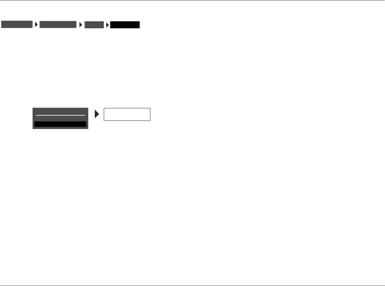
RV-5 Mode Adjust
6-29
RESET MODE
Restores the factory-default version of the selected listening mode,
restoring all listening mode menu parameters to their factory default
settings.
To restore the factory-default version of the selected listening mode:
1. Follow the RESET MODE menu path to select the RESET MODE
option. The PRESS RIGHT V TO RESTORE MODE message
appears in the on-screen display.
2. Press the arrow button to restore the factory-default version of
the selected listening mode. Press the arrow button to close the
message without restoring the factory-default.
Note:
When the CUSTOM menu RESET MODE option is selected to restore the
factory-default version of the selected listening mode, the corre-
sponding TRIGGER SETUP menu listening mode parameter is
automatically set to OFF.
(Listening Mode)
MODE ADJUST CUSTOM RESET MODE
CUSTOM
CUSTOM VS PRESET
RESET MODE
PRESS RIGHT V
TO RESTORE MODE

Mode Adjust Lexicon
6-30
LISTENING MODE MENU OPTION and PARAMETER DESCRIPTIONS
5 SPKR ENHANCE ON, OFF
Simulates 7-channel playback in 5-channel speaker configurations.
When set to ON, the RV-5 provides an increased sense of
spaciousness and envelopment through the surround speakers. This
enhancement is most noticeable when the surround speakers are
positioned to the side of the primary listening position, or when the
primary listening position is located against the rear wall. The effec-
tiveness of this parameter varies within the listening space. For best
results, it is recommended that you position the surround speakers
to the left and right sides of the primary listening position.
ACADEMY FILTER ON, OFF
When set to ON, restores the proper tonal balance of older mono
film sources that have much narrower frequency responses than
more recent mono film sources.
AUTO AZIMUTH ON, OFF
Maximizes matrix steering accuracy. When set to ON, the RV-5
continually monitors the 2-channel input signal and automatically
adjusts the relative level and time offset of the input channels to
ensure that signals are sent to the appropriate channels with
maximum separation. When set to OFF, the accuracy of the selected
listening mode varies among sources. It is recommended that you
set this parameter to ON for film and broadcast sources and to OFF
for music sources.
BASS CONTENT BINAURAL, MONO, STEREO
Adjusts the bass content of binaural, mono and stereo recordings.
When set to BINAURL, the RV-5 activates low-frequency compen-
sation. Select this setting for true binaural sources recorded with
dummy head microphones. Select the MONO setting for sources
recorded with mono bass. Select the STEREO setting for sources
recorded with stereo bass.
BASS ENHANCE ON, OFF
Enhances stereo bass, which results in low-frequency reproduction
that is less localizable and more realistic in the listening space. The
effectiveness of the BASS ENHANCE parameter varies, depending
on room acoustics and the ability of the surround speakers to
reproduce low frequencies. It is recommended that you use front,
side or rear speakers that are capable of reproducing frequencies of
40Hz or lower.
BASS RT 5ms to 48.6s
Works with the MID RT and SIZE parameters to adjust the amount
of time required for low-frequency information to decay below 60dB
in level. The BASS RT parameter setting should match the MID RT
parameter setting for more natural effects in smaller listening spaces.
CAUTION!
Setting the BASS RT, MID RT and SIZE parameters to a high
value may produce undesirable or damaging audio.
BASS XOVER 30Hz to 19.9kHz, OFF
Sets the frequency to which BASS RT applies.
CALIBRATION
Opens the PANORAMA listening mode CALIBRATION menu, which
is used to calibrate the PANORAMA listening mode. Refer to
“PANORAMA” on page 6-11 for more information.

RV-5 Mode Adjust
6-31
LISTENING MODE MENU OPTION and PARAMETER DESCRIPTIONS (continued)
CENTER OFF, –30 to +12dB
Controls the output level of the audio output connector labeled Center.
Available in all except 2 CH modes (2-CHANNEL, 2 CH BYPASS,
DTS(-ES) 2-CHAN, 5.1 2-CHANNEL), MONO, 5.1 MONO and LIVE!
modes.
CENTER DEPTH 0 to 18
Adjusts the amount of processing applied to the center channel,
changing the perceived distance of the center speaker. Higher
settings increase and lower settings decrease the perceived distance
of the center speaker from the listening position. Available in
NIGHTCLUB, CONCERT HALL, CHURCH and CATHEDRAL modes.
CENTER MIX –25 to +5dB
Indicates the relative center channel level for downmixing. Set this
parameter to +0dB for film sources and –5dB for music sources.
Available in 5.1 2-CHANNEL and DTS(-ES) 2-CHAN modes.
CNTR DLY SAMPLES –127 to +127
Controls the relative time offset of the center channel. Set this
parameter to +0 unless the center channel is not properly timed
and the value of the error is known. Available in 5.1 2-CHANNEL and
DTS(-ES) 2-CHAN modes.
COMPRESSION AUTO, ON, OFF
Reduces wide volume level changes and increases dialogue intelligi-
bility at lower listening levels for Dolby Digital input sources. When
ON, full compression is applied, regardless of volume level. When OFF,
compression is not applied. Set this parameter to AUTO or ON for
Dolby Digital input sources that are listened to at lower volume levels,
especially for nighttime viewing to avoid disturbing others. Available in
all Dolby Digital modes.
CTR WIDTH MIN, 1 to 6, MAX
Adjusts the center image. When set to MIN, the center image is heard
from just the center speaker. When set to MAX, the center image is
heard as a “phantom” center image from the front left and right
speakers. When set on the 1 to 6 scale, the center image is heard in
various combinations of the front and center speakers. Available in
Dolby PLII MUSIC and Dolby PLIIx MUSIC modes.
CUSTOM
Opens the CUSTOM menu, which is used to compare custom and
factory-default versions of the selected listening mode and to restore
the factory default version of the selected listening mode. Available in
all modes.
CUSTOM VS PRESET
Allows comparison listening to the custom and factory-default versions
of the selected listening mode. Refer to page 5-32 for information.
Available in all modes.
DIMENSION FRONT, NEUTRAL, REAR
Controls the relative balance of the sound field, which can be useful
with certain recordings to achieve a more suitable balance among
all speakers. When set to FRONT, the sound field is balanced toward
the front of the listening space. When set to NEUTRAL, the sound
field is balanced at the center of the listening space. When set to
REAR, the sound field is balanced toward the rear of the listening
space. Available in Dolby PLII MUSIC and Dolby PLIIx MUSIC modes.

Mode Adjust Lexicon
6-32
EARLY RFLX LVL –80dB to +12dB, OFF
Controls the amount of additional early reflections. Available in all
LIVE! modes.
EFFECT LVL –12 to +6dB
Adjusts the amount of effect applied to the listening mode. Available
in NIGHTCLUB, CONCERT HALL, CHURCH, CATHEDRAL, PANORAMA,
MONO LOGIC and 5.1 MONO LOGIC modes.
ES DECODING AUTO, ON, OFF
Controls DTS-ES decoding, which extracts a rear channel from
5.1-channel DTS, 5.1-channel matrix-encoded DTS-ES and
6.1-channel discrete-encoded DTS-ES sources. When ON is
selected, DTS-ES decoding is activated for all DTS-ES sources. When
OFF is selected, DTS-ES decoding is deactivated for all DTS-ES sources.
DTS-ES decoding is activated when AUTO is selected and a 5.1-channel
matrix-encoded or a 6.1-channel discrete-encoded DTS-ES source is
detected. DTS-ES decoding is deactivated when a 5.1-channel DTS
source is detected.
DTS-ES listening modes are available when DTS-ES decoding is
engaged. DTS listening modes are available when DTS-ES decoding
is not engaged. Refer to the DTS-ES Decoding section that begins
on page 5-25 for more information.
Note the following:
• DTS-ES decoding cannot be engaged unless both side and rear
speakers are present.
• The DTS-ES STATUS menu includes an SB level meter when the
ES DECODING parameter is set to ON and a 5.1-channel DTS
source is present or when the ES DECODING parameter is set to
AUTO and a 5.1-channel matrix-encoded or 6.1-channel
discrete-encoded DTS-ES source is present.
This parameter is available in all DTS modes.
EX DECODING AUTO, ON, OFF
Controls Dolby Digital Surround EX decoding, which extracts a rear
channel from 5.1-channel Dolby Digital sources recorded with or
without Dolby Digital Surround EX. When ON, Dolby Digital
Surround EX decoding is engaged for all 5.1-channel Dolby Digital
sources. When OFF, Dolby Digital Surround EX decoding is disen-
gaged for all 5.1-channel Dolby Digital sources.
When AUTO is selected, Dolby Digital Surround EX decoding is
engaged when a flagged 5.1-channel Dolby Digital source recorded
with Dolby Digital Surround EX encoding is detected. Dolby Digital
Surround EX decoding is not engaged when a non- flagged
5.1-channel Dolby Digital source recorded with or without Dolby
Digital Surround EX encoding is detected.
Note:
The RV-5 cannot automatically detect Dolby Digital Surround EX encoding
in non-flagged 5.1-channel Dolby Digital sources. A non-flagged input
source does not identify Dolby Digital Surround EX encoding in the input
signal.
The Dolby DIGITAL EX listening mode is available when Dolby
Digital Surround EX decoding is engaged. The Dolby DIGITAL
listening mode is available when Dolby Digital Surround EX
decoding is not engaged. Refer to the Dolby DIGITAL EX & Dolby
DIGITAL listening mode descriptions that begin on page 5-22 for
more information.
Note the following:
• Dolby Digital Surround EX decoding cannot be engaged unless
both side and rear speakers are present.

RV-5 Mode Adjust
6-33
LISTENING MODE MENU OPTION and PARAMETER DESCRIPTIONS (continued)
• This parameter is available in 5.1 PLIIx MOV, 5.1 PLIIx MUS,
DOLBY DIGITAL EX and DOLBY DIGITAL modes.
• When the Shift command bank is activated, pressing the
remote control DOLBY button while a 5.1-channel Dolby
Digital source is present activates the Dolby DIGITAL EX or
Dolby DIGITAL listening mode. Subsequent presses adjust the
EX DECODING parameter, cycling through the AUTO, ON and
OFF settings.
FRONT STEERING OFF, MSURR, MUSIC, FILM
Adjusts front steering between the front left, front right, and center
speakers. When set to FILM, maximum front steering is applied to
the center channel. When set to MUSIC, moderate front steering is
applied. When set to MSURR, minimum front steering is applied.
When set to OFF, no front steering is applied. It is recommended
that you set this parameter to FILM for film and broadcast sources
and to MUSIC, MSURR or OFF for music sources. Available in L7 TV,
L7 MUSIC, L7 MUSIC SURR, all 5.1 L7 modes and all DTS L7 modes.
INPUT BALANCE L< to <|> to >R
Controls the balance of the selected stereo analog audio input
connectors, compensating for audio input sources with audible
channel imbalance. Available in PANORAMA mode.
LFE MIX –20.0 or -10.0 to +0.0dB
Controls the output level of LFE information – the .1 channel in a 5.1-
or 6.1-channel input source – that is sent to the audio output labeled
Subwoofer. Low frequencies from up to seven other channels might be
combined with the LFE information to create the subwoofer output
signal, which significantly increases subwoofer output levels.
Careful adjustment of this parameter allows achievement of proper
tonal balance and reduces the risk of subwoofer overload. When the
speaker setup does not include a subwoofer, LFE information is mixed
into speakers for which the corresponding CUSTOM SETUP menu
parameter is set to FULL or to the lowest crossover points. Available in
all Dolby Digital modes except MONO modes (5.1 MONO LOGIC, 5.1
MONO SURR, 5.1 MONO) and all DTS modes.
LISTENER POS –127 to +127
Compensates for primary listening positions that are not centered
between the front left and right speakers. Each increment within the
–127 to +127 parameter range represents about one-third of an inch.
Refer to the Calibration section that begins on page 5-13 for more
information. Available in PANORAMA CALIBRATION mode.
Note:
The LISTENER POS parameter range might extend past the location of the
front left and right speakers.
LIVENESS 30ms to 20.2s
Depends on the SIZE parameter setting. The LIVENESS parameter
adjusts the amount of effect recirculation. Higher settings mimic
more reflective surfaces and increase decay time. Available in
NIGHTCLUB and CONCERT HALL modes.
LOW FREQ WIDTH –25 to +25dB
Applies low-frequency spatial correction to the input signal. This
correction is applied to uncorrelated input signals below 60Hz.
Available in PANORAMA mode.

Mode Adjust Lexicon
6-34
MASTER LEVEL –5 to +5dB
Adjusts the output level of 2-channel Logic 7-encoded sources.
Available in 5.1 2-CHANNEL and DTS(-ES) 2-CHAN modes.
MID RT 24ms to 24.3s
Works with the SIZE parameters to adjust the amount of time
required for mid-frequency information to decay below 60dB in
level. The full parameter range might not be available depending
on the SIZE parameter setting. Available in CHURCH, CATHEDRAL
and all LIVE! modes.
CAUTION!
Setting the BASS RT, MID RT or SIZE parameters to a high
value may produce undesirable or damaging audio.
OUTPUT LEVELS
Opens the OUTPUT LEVELS menu, which is used to adjust output
levels for the Main Zone audio output connectors labeled Center,
Subwoofer, Side L/R and Rear L/R. Refer to page 5-32 for more
information. Available in all except 2-CHANNEL, MONO, 5.1
2-CHANNEL, 5.1 MONO, DTS (-ES) 2-CHAN, 2CH BYPASS and
LIVE! modes.
PANORAMA ON, OFF
When set to ON, Dolby PLII MUSIC and Dolby PLIIx MUSIC listening
modes extend the front stereo image to include surround channel
signals, which creates a “wraparound” effect with side wall imaging.
Available in Dolby PLII MUSIC and Dolby PLIIx MUSIC modes.
Note:
The PANORAMA parameter within the Dolby PLII MUSIC and Dolby PLIIx
MUSIC listening modes should not be confused with the separate
PANORAMA listening mode (page 6-11).
PRE-DELAY 1 to 100ms, OFF
Adjusts delay time between the direct sound and the onset of rever-
beration. Higher settings make the simulated space sound larger.
Because some pre-delay is inherent in all source material, you
should begin with the parameter set to the lowest setting, then
make adjustments accordingly. Available in NIGHTCLUB, CONCERT
HALL, CHURCH, CATHEDRAL and all LIVE! modes.
RE-EQUALIZER ON, OFF
Simulates high-frequency rolloffs that occur in movie theaters.
When set to ON, the RV-5 applies a high-frequency filter. When set
to OFF, the RV-5 does not apply a high-frequency filter. It is recom-
mended that you set this parameter to ON for film sources, as many
films are mixed for movie theaters and might sound too bright
when played back in home theaters without re-equalization.
Available in L7 FILM, L7 TV, Dolby PLII + THX, Dolby PLIIx + THX, 5.1
L7 FILM, 5.1 L7 TV, THX ULTRA2, THX SurEX, THX, DTS (-ES) L7 FILM,
DTS(-ES) THX ULTRA2 and DTS(-ES) THX modes.
REAR DLY OFFSET OFF, 1 to 30ms
Increases the perceived depth of the listening space by delaying the
arrival time of rear speaker signals. It is recommended that you
increase the setting when using side and rear speakers that are
located close together or when a greater sense of depth is desired in
the listening space. Available in all Logic 7 modes and PANORAMA
mode.

RV-5 Mode Adjust
6-35
LISTENING MODE MENU OPTION and PARAMETER DESCRIPTIONS (continued)
REAR L/R –30 to +12dB, OFF
Controls the output level of the Main Zone audio output connector
labeled Rear L/R. Available in all except 2-CHANNEL, MONO, 5.1
2-CHANNEL, 5.1 MONO, DTS (-ES) 2-CHAN, 2CH BYPASS and
LIVE! modes.
RESET MODE
Restores the factory-default version of the selected listening mode,
restoring all listening mode menu parameters to their factory-
default settings. Available in all modes.
REVERB LVL –80 to +0dB, OFF
Controls the amount of added reverb. Available in all LIVE! modes.
ROLLOFF 500Hz to 20.0kHz, OFF
Simulates the absorption of high frequencies in a real space. It is
recommended that you begin with a low setting to simulate high-
frequency absorptive spaces. Available in NIGHTCLUB, CONCERT
HALL, CHURCH, CATHEDRAL and all LIVE! modes.
SHAPE 0 TO 4
Controls the buildup of the energy that most audibly creates the
sound of a real room. SHAPE and SPREAD work together – if either is
set to zero, the other has no effect. Available in all LIVE! modes.
SIDE L/R –30 to +12dB, OFF
Controls the level of the Side L/R audio output connectors in the Main
Zone. Available in all except 2-CHANNEL, MONO, 5.1 2-CHANNEL,
5.1 MONO, DTS (-ES) 2-CHAN, 2CH BYPASS and LIVE! modes.
SIZE 4 to 20 or 30m
Adjusts the length of the listening space within a 4m to 20m or
30m range (depending on the listening mode). Increase the size of
the space to increase the reverb effect. Available in NIGHTCLUB,
CONCERT HALL, CHURCH, CATHEDRAL and all LIVE! modes.
CAUTION!
Setting the BASS RT, MID RT and SIZE parameters to a high
value may produce undesirable or damaging audio.
SOUND STAGE FRONT, NEUTRAL, REAR
Dynamically controls the relative balance of the audio output
connectors. When set to FRONT, Side L/R and Rear L/R output levels
are attenuated by 6dB, shifting the perceived balance of the sound
field to the front of the listening space. When set to NEUTRAL, Side L/R
and Rear L/R output levels are slightly attenuated by 3dB, shifting the
perceived balance of the sound field to the center of the listening
space. When set to REAR, Side L/R and Rear L/R output levels are not
attenuated, preserving the intended balance of the sound field.
Available in all Logic 7 modes.

Mode Adjust Lexicon
6-36
SOURCE RIGHT, LEFT & RIGHT, LEFT
Controls the perceived direction of the PANORAMA listening mode
external calibration source signal. When RIGHT is selected, the
sound is perceived to come from the right of the primary listening
position. When LEFT is selected, the sound is perceived to come
from the left of the primary listening position. When LEFT & RIGHT
is selected, the sound is perceived to come from all around the
primary listening position. Refer to the Calibration section that
begins on page 6-11 for more information about the SOURCE
parameter. Available in PANORAMA CALIBRATION.
Note:
The SOURCE parameter controls the perceived direction of the sound,
although both the front left and right speakers generate the external
calibration source signal.
SPEAKER ANGLE 10 to 90deg
Compensates for a wide or narrow speaker angle relative to the
primary listening position. Select the setting closest to the angle
between the front left and right speakers and the primary listening
position. Refer to the Calibration section that begins on page 6-11
for more information about the SPEAKER ANGLE parameter.
Available in PANORAMA CALIBRATION.
SPEECH DETECT ON, OFF
Distinguishes monaural speech from other input sources. When set to
ON, effects are lowered to minimize interference and unnatural echo
in monaural speech. When stereo input sources are present, the front
left and right channels are independently used as inputs for ambience
synthesis. When strong monaural speech is present in the input source,
the monaural component of the ambience effect is reduced and the
stereo component of the effect is increased. When set to OFF, the
amount of ambience synthesis is dynamically controlled. Available in
NIGHTCLUB, CONCERT HALL, CHURCH and CATHEDRAL modes.
SPREAD 0 to 100%
Controls the timing between the initial reflections that most audibly
create the sound of a real room. SHAPE and SPREAD work together; if
either is set to 0, the other has no effect. Available in all LIVE! modes.
SUB & SUB LVL OFF, –30 to +12dB
Controls the output level of the Main Zone audio output connector
labeled Subwoofer. The SUB parameter appears on the listening
mode OUTPUT LEVELS menu. The SUB LVL parameter appears on
listening mode menus when the listening mode does not accom-
modate multichannel output signals. Available in all except LIVE!
modes.
SURR ROLLOFF 500Hz to 20.0kHz, OFF
Applies high-frequency attenuation control to the audio output
connectors labeled Side L/R and Rear L/R. This filter is only applied to
output signals generated by the RV-5. Available in all Logic 7 modes.
SURROUND DLY 0 to 15ms
Increases the perceived depth of the listening space by delaying the
arrival time of signals from the side and rear speakers. It is recom-
mended that you increase the setting when a greater sense of
depth is desired in the listening space.
SURROUND EX AUTO, ON, OFF
Controls the THX Surround EX decoding feature, which can be used to
extract a rear channel from 5.1-channel Dolby Digital sources. When
ON is selected, THX Surround EX decoding is engaged for all
5.1-channel Dolby Digital sources. When OFF is selected, THX
Surround EX decoding is not engaged for all 5.1-channel Dolby Digital
sources. Available in THX ULTRA2, THX SurEX and THX modes.

RV-5 Mode Adjust
6-37
LISTENING MODE MENU OPTION and PARAMETER DESCRIPTIONS (continued)
SURROUND MIX -5 to +5dB
Controls the relative level of surround channel information sent to the
audio output connectors labeled Front L/R. It is recommended that
you set this parameter to +2dB or +3dB for all input sources. Available
in 5.1 2-CHANNEL and DTS (-ES) 2-CHAN modes.
TREB CUT RT 500Hz to 20kHz
Sets the frequency above which high frequencies are rolled off in
the reverberated signal, causing reverberated signals to grow
progressively darker. This results in a more natural sound because it
simulates the effect of air absorption in a real hall. Setting this
parameter to a low frequency dampens the audio as it re-circulates,
and consequently can actually shorten the reverb time. Available in
all LIVE! modes.
VOCAL ENHANCE +6.0dB, +3.0dB, +0.0dB
Controls the level of dialog-boost in the audio output connector
labeled Center. Increase this setting to improve dialog intelligibility,
particularly at lower volume levels. Available in all Logic 7 modes.
Mode Adjust Lexicon
6-38
MODE – PARAMETER RELATIONSHIPS
The following table lists each parameter and the modes in which it is used.
The parameter... Is used in these modes
5 SPKR ENHANCE All L7 modes
ACADEMY FILTER MONO LOGIC and 5.1 MONO LOGIC
AUTO AZIMUTH L7 FILM and L7 TV
BASS CONTENT PANORAMA
BASS ENHANCE All L7 modes
BASS RT CHURCH, CATHEDRAL and all LIVE! modes
CALIBRATION PANORAMA
CENTER All except 2 CH modes (2-CHANNEL, 2 CH BYPASS, DTS(-ES) 2-CHAN, 5.1 2-CHANNEL, MONO, 5.1 MONO and
LIVE! modes)
CENTER DEPTH NIGHTCLUB, CONCERT HALL, CHURCH, CATHEDRAL
CENTER MIX 5.1 2-CHANNEL, DTS(-ES) 2-CHAN
CNTR DLY SAMPLES 5.1 2-CHANNEL, DTS(-ES) 2-CHAN
COMPRESSION All Dolby Digital modes
CTR WIDTH Dolby PLII MUSIC and Dolby PLIIx MUSIC
CUSTOM All modes
CUSTOM VS PRESET All modes
DIMENSION Dolby DPLII MUSIC and Dolby PLIIx MUSIC
EARLY RFLX LVL All LIVE! modes
EFFECT LVL NIGHTCLUB, CONCERT HALL, CHURCH, CATHEDRAL, PANORAMA, MONO LOGIC and 5.1 MONO LOGIC
ES DECODING All DTS modes

RV-5 Mode Adjust
6-39
EX DECODING 5.1 PLIIx MOV, 5.1 PLIIx MUS, DOLBY DIGITAL EX and DOLBY DIGITAL
FRONT STEERING L7 TV, L7 MUSIC, L7 MUSIC SURR, all 5.1 L7 modes and all DTS L7 modes
INPUT BALANCE PANORAMA
LFE MIX All Dolby Digital modes except MONO modes (5.1 MONO LOGIC, 5.1 MONO SURR, 5.1 MONO), all DTS modes
and 5.1a BYPASS
LISTENER POS PANORAMA CALIBRATION
LIVENESS NIGHTCLUB, CONCERT HALL
LOW FREQ WIDTH PANORAMA
MASTER LEVEL 5.1 2-CHANNEL, DTS(-ES) 2-CHAN
MID RT CHURCH, CATHEDRAL and all LIVE! modes
OUTPUT LEVELS All except 2-CHANNEL, MONO, 5.1 2-CHANNEL, 5.1 MONO, DTS(-ES) 2-CHAN, 2CH BYPASS and LIVE! modes
PANORAMA Dolby PLII MUSIC and Dolby PLIIx MUSIC
PRE-DELAY NIGHTCLUB, CONCERT HALL, CHURCH, CATHEDRAL and all LIVE! modes
RE-EQUALIZER L7 FILM, L7 TV, Dolby PLII + THX, Dolby PLIIx + THX, 5.1 L7 FILM, 5.1 L7 TV, THX ULTRA2, THX SurEX, THX, DTS
(-ES) L7 FILM, DTS (-ES) THX ULTRA2 and DTS (-ES) THX
REAR DLY OFFSET All L7 modes and PANORAMA
REAR L/R All except 2-CHANNEL, MONO, 5.1 2-CHANNEL, 5.1 MONO, DTS(-ES) 2-CHAN, 2CH BYPASS and LIVE! modes
RESET MODE All modes
REVERB LVL All LIVE! modes
ROLLOFF NIGHTCLUB, CONCERT HALL, CHURCH, CATHEDRAL and all LIVE! modes
SHAPE All LIVE! modes
SIDE L/R All except 2-CHANNEL, MONO, 5.1 2-CHANNEL, 5.1 MONO, DTS(-ES) 2-CHAN, 2CH BYPASS and LIVE! modes
SIZE NIGHTCLUB, CONCERT HALL, CHURCH, CATHEDRAL and all LIVE! modes
The parameter... Is used in these modes
Mode Adjust Lexicon
6-40
SOUND STAGE All L7 modes
SOURCE PANORAMA CALIBRATION
SPEAKER ANGLE PANORAMA CALIBRATION
SPEECH DETECT NIGHTCLUB, CONCERT HALL, CHURCH and CATHEDRAL
SPREAD All LIVE! modes
SUB & SUB LVL All except LIVE! modes
SURR ROLLOFF All L7 modes
SURROUND DLY Dolby PLII MUSIC and Dolby PLIIx MUSIC
SURROUND MIX 5.1 2-CHANNEL and DTS(-ES) 2-CHAN
TREB CUT RT All LIVE! modes
VOCAL ENHANCE All L7 modes
The parameter... Is used in these modes

7
Troubleshooting and Maintenance
Troubleshooting..........................................................................7-2
Routine Maintenance ..................................................................7-4
Restoring Factory-Default Settings...............................................7-4

Troubleshooting and Maintenance Lexicon
7-2
TROUBLESHOOTING
The RV-5 does not power on.
1. Make sure the rear-panel power switch is set to the | (“on”)
position.
2. Attempt to power on the RV-5 with the front-panel Standby
button and remote control On button.
3. Examine the power cord to ensure a good connection between
the rear-panel AC input connector and the wall outlet.
4. Check the electrical circuit and breaker.
The remote control does not work.
1. Eliminate obstructions between the remote control and the
front-panel IR receiver. When the RV-5 is not using the rear-
panel IR IN connector, the remote control must be in line of
sight with the front-panel IR receiver for proper operation. The
remote control might also become unreliable if strong sunlight
or fluorescent light is shining on the IR receiver.
2. Make sure the remote control batteries are correctly inserted
with the proper polarity (page 1-6).
3. Replace the remote control batteries. When the batteries are
low on power, the remote control enters a low-voltage
condition that prevents it from operating the RV-8.
The RV-5 is powered on, but there is no audio.
1. Make sure volume level is audible. Volume level can be
increased with the front-panel volume knob or the remote
control VOL and buttons.
2. Make sure audio has not been muted. The message “MUTE
ON” or “FULL MUTE ON” will appear in the on-screen and
front-panel displays when audio has been muted. To deactivate
mute, press the Mute button or adjust the volume level.
3. Check the INPUT SETUP menu DIGITAL IN and ANALOG IN
parameters to ensure the appropriate audio connector is assigned
to the selected input.
4. Make sure the RV-5 is receiving an audio signal. To do this,
follow the instructions that begin on page 2-29 to open the
STATUS menu for the current input source.
Dialogue sounds muffled.
If the speaker setup does not include a center speaker, make sure a
custom – as opposed to a THX – speaker setup is selected. Then,
make sure the CUSTOM SETUP menu CENTER parameter is set to
NONE (page 3-31).
A humming sound is present in the audio.
1. If a cable TV connection is present, disconnect the cable from
the wall outlet. If this eliminates the humming sound, a ground
loop isolation device is required. Contact your dealer or the
cable provider for assistance.
2. Disconnect components one at a time to isolate the problem.
Once the problem is identified, make sure the associated
component is properly grounded and connected to the same
electrical circuit as the RV-5.
The RV-5 is powered on, but there is no video.
1. Examine the video cables – particularly the S-Video cables –
to ensure a good connection to the associated component.

RV-5 Troubleshooting and Maintenance
7-3
2. Check the INPUT SETUP menu VIDEO IN and COMPONENT IN
(page 3-11) parameters to ensure the appropriate video
connector is assigned to the selected input.
RF interference is present in the audio or video.
1. Make sure the RV-5 is not positioned near unshielded TV or FM
antennas, cable TV decoders and other RF-emitting devices.
2. Replace unshielded cables with shielded cables wherever possible.
The RV-5 is exhibiting erratic behavior.
1. Set the rear-panel power switch to the c (“off”) position. Wait
10 seconds. Then set the rear-panel power switch to the |
(“on”) position.
2. Use the RV-5 configuration tool to download the current RV-5
configuration to a personal computer (PC) or document all user-
defined settings on the Installation Worksheet that begins on
page D-2. Then, follow the instructions on the next page to
restore factory-default settings.
If all else fails...
1. Document all user-defined settings on the Installation
Worksheet that begins on page D-2. Then, follow the instruc-
tions on page 7-4 to restore factory-default settings.
2. Contact an authorized Lexicon dealer.
3. Contact Lexicon customer service at 781-280-0300 or
www.lexicon.com.
Note:
Visit the knowledgebase at http://www.lexicon.com/kbase for
answers to frequently asked questions and additional trouble-
shooting information.
The tuner volume suddenly went mute, then after a minute it
resumed. This seems to happen occasionally.
Under the TUNER SETUP menu, is the AUTO FREQUENCY option
active? You may be experiencing broadcast station dropouts. When
the broadcast signal drops out, the volume is muted and AUTO
FREQUENCY activates, scanning for alternate broadcast frequencies
and then verifying that the station ID is an exact match. If the
station ID matches and the alternate frequency is a stronger signal,
then the tuner switches to the alternate frequency and turns off the
volume mute. Otherwise, auto frequency scans for another
alternate frequency and repeats the procedure. If there are a lot of
alternate broadcast frequencies, this process can take a noticeable
amount of time. To stop this behavior, simply turn off the Auto
frequency option.

Troubleshooting and Maintenance Lexicon
7-4
ROUTINE MAINTENANCE
The bulleted items below describe routine maintenance that should
be performed on a periodic basis.
• Clean the RV-5 exterior surface with a soft, lint-free cloth. Do
not use alcohol, benzene, acetone-based cleaners or strong
commercial cleaners. Do not use a cloth made with steel wool
or metal polish. If the RV-8 is exposed to a dusty environment, a
low-pressure blower can be used to remove dust from its
exterior surface.
• Replace the remote control batteries as needed. The remote
control requires four AAA batteries. When these batteries are
low on power, the remote control enters a low-voltage
condition that prevents it from operating the RV-5. Normal
operation will resume when new batteries are installed.
RESTORING FACTORY-DEFAULT SETTINGS
When factory-default settings are restored, all parameters and user-
defined values are restored to their factory-default settings. Before
restoring factory-default settings, record all user-defined settings in
the Installation Worksheet in the Appendix on page D-2.
To restore factory-default settings:
1. Record all user-defined settings on the Installation Worksheet
that begins on page D-2. When factory-default settings are
restored, all parameters and user-defined values are restored to
their factory-default settings.
2. If the RV-5 is powered on, press the front-panel standby button
or the remote control Off button to activate standby mode and
deactivate the RV-5. If the RV-5 is in standby mode, proceed to
step 3.
3. Press the front-panel standby button or the remote control On
button to deactivate standby mode and activate the RV-5.
4. Quickly press and hold the front-panel or remote control Mute
button until the FACTORY SETTINGS menu opens in the on-
screen and front-panel displays.
5. Press the remote control and arrow buttons to highlight
the desired option. Highlight the RESTORE DEFAULTS option to
restore factory-default settings. Highlight the EXIT option to
close the FACTORY SETTINGS menu without restoring factory-
default settings.
6. When the desired option is highlighted, press the remote
control arrow button to select this option.
• If the RESTORE DEFAULTS option was selected, the
FACTORY SETTINGS message shown in the previous page
will appear in the on-screen and front-panel displays. When
this message appears, press a front-panel or remote control
button to restart the RV-5.
• If the EXIT option is selected, the FACTORY SETTINGS menu
will close and the two-line status will open in the on-screen
and front-panel displays.
FACTORY SETTINGS
EXIT
RESTORE DEFAULTS
FACTORY SETTINGS
HAVE BEEN RESTORED
PRESS ANY KEY
TO RESTART

A
Appendix
Specifications ............................................................................. A-2
Declaration of Conformity.......................................................... A-4
Menu Tree ................................................................................. A-5
Installation Worksheet .............................................................. A-20
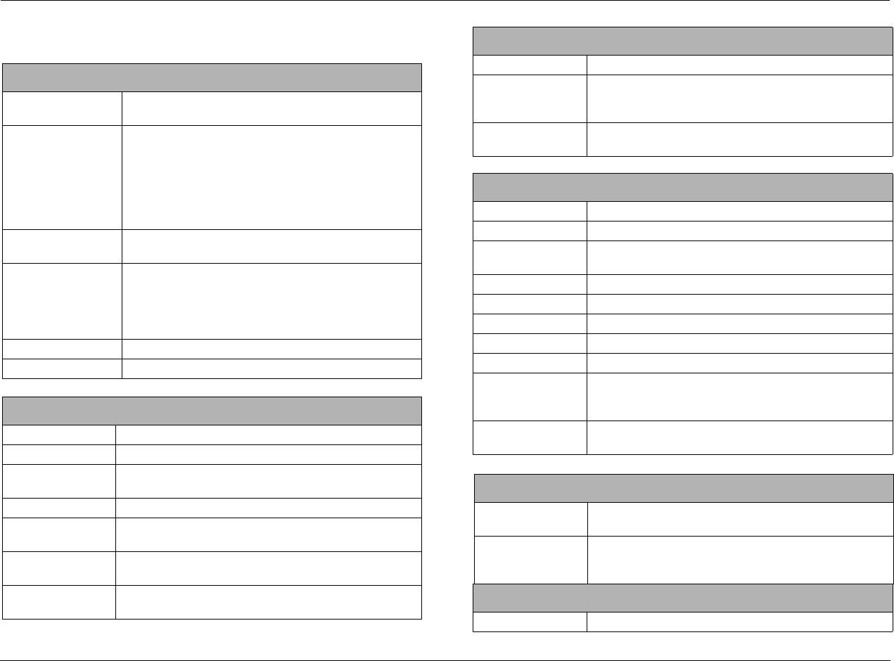
Appendix Lexicon
A-2
SPECIFICATIONS
Audio Input & Output Connectors
Analog Audio Inputs Eight stereo (RCA) or five stereo and one 5.1-channel or 2
stereo and two 5.1-channel connectors
Digital Audio Inputs • Four S/PDIF coaxial (RCA) and four S/PDIF optical
connectors
• Coaxial and optical input connectors conform to IEC-
958, S/PDIF standards
• Accepts 44.1, 48, 88.2 and 96kHz sample rates
• Accepts 16-24-bit PCM audio, Dolby Digital, DTS and
DTS-ES discrete data formats
Main Zone Audio
Outputs
Eight unbalanced (RCA) connectors for Front L/R, Center,
Sub, Side L/R and Rear L/R
Zone 2 Audio Outputs • One unbalanced (RCA, variable output level) stereo con-
nector
• One unbalanced (RCA, fixed output level) stereo connector
• One S/PDIF coaxial (RCA) connector and one optical con-
nector
Headphone One stereo (1/4-inch phone) connector
Amplifier Seven channels, two channels assigned to Zone 2 or Zone 3
Main Zone Audio Performance
A/D Conversion 24-Bit, 96kHz, dual-bit ΔΣ architecture
D/A Conversion 24-Bit, 44.1 to 192kHz, multibit ΔΣ architecture
*Frequency Response 20Hz to 20kHz, +0.1dB/–0.1dB, –0.25dB at 40kHz,
–0.5dB at 40kHz, reference 1kHz
*THD + Noise Below 0.02%, 20Hz to 20kHz, 140W Rms all channels driven
*Dynamic Range • 105dB minimum, 22kHz bandwidth, “A” weighted
• 102dB minimum, 22kHz bandwidth, unweighted
*Signal-to-Noise Ratio • 105dB minimum, 22kHz bandwidth, “A” weighted
• 102dB minimum, 22kHz bandwidth, unweighted
Input Sensitivity 200mV Rms (2V Rms for maximum output level) at 0dB
input gain
Input Impedance 100kΩ in parallel with 150pF
Preamp Output Level • 150mV Rms typical, 6V Rms maximum (RCA connectors)
• Maximum value with full-scale input signal and volume
at +12dB
Preamp Output
Impedance
500Ω in parallel with 150pF (RCA connectors)
Zone 2 Audio Performance
A/D Conversion 24-Bit, 44.1 to 96kHz, multibit ΔΣ architecture (Zone 2 only)
D/A Conversion 24-Bit, 44.1 to 192kHz, multibit ΔΣ architecture
Frequency Response 10Hz to 20kHz, +0.1dB/–0.25dB, –0.75dB at 40kHz,
reference 1kHz
THD + Noise Below 0.005% at 1kHz, (1V Rms output level)
Dynamic Range 101dB minimum, 22kHz bandwidth
Signal-to-Noise Ratio 101dB minimum, 22kHz bandwidth
Input Sensitivity 200mV Rms (4V Rms for maximum output level)
Input Impedance 100kΩ in parallel with 150pF
Preamp Output Level • 200mV Rms typical, 4V Rms maximum
• Maximum value with full-scale input signal and volume
at 0dB
Preamp Output
Impedance
300Ω in parallel with 150pF
Video Input & Output Connectors
Video Inputs Five composite (RCA), five S-Video and three component
video (RCA)
Video Outputs Two composite (RCA, one monitor and one Zone 2), two
S-Video (one monitor and one Zone 2) and one component
(RCA)
Composite & S-Video Performance
Compatibility NTSC, PAL and SECAM
Main Zone Audio Performance
RV-5 Appendix
A-3
Switching Active
Output Level 1.0V peak-to-peak
Impedance 75Ω
Input Return Loss >40dB
Differential Gain <0.5%
Differential Phase <0.5°
Bandwidth >25MHz
K Factor <0.3%
Gain ±0.15dB
Signal-to-Noise Ratio >65dB
Frequency Response 10Hz to 10MHz + 0.1/–0.3dB
Component Video Performance
Compatibility 3-Channel (Y, Pr, Pb), format-independent
Switching Passive
Impedance 75Ω
Insertion Loss <3dB
Bandwidth >150MHz
Video Converter NTSC, PAL, SECAM, to Y/Pb/Pr
Microphone Input Connectors
Inputs 4 3.5mm miniature phone jacks
Input Sensitivity 10mV Rms (400mV maximum input level)
Input Impedance 20kΩ (accepts balanced or unbalanced input signals)
FM Tuner Performance
Tuning Range 64MHz to 108MHz
Usable Sensitivity <4uV, 1.6mV typical
Selectivity >87dBmV, 93dBmV typical
Composite & S-Video Performance
Frequency Response 50Hz to 16kHz, +0.1dB/-1.0dB
THD + Noise <0.4% at 1 kHz (stereo)
Signal-to-Noise Ratio 50dB minimum at 60dBmV
Image Rejection >50dB, >60dB typical
AM Suppression >45dB, >55dB typical
AM Tuner Performance
Tuning Range 520 to 1720kHz
Usable Sensitivity <8uV, 4mV typical
THD + Noise < 0.56%, 0.20% typical (1kHz, 60dBmV, 30% mod)
Wideband AGC >80dBmV
Phono Performance (MM)
Frequency Response 50Hz to 20kHz, +0.5dB/-0.5dB, rumble filter -4dB at 10Hz
THD + Noise < 0.20%, 20Hz to 10kHz, 4.7mV input
Signal-to-Noise Ratio 72dB minimum
Compatible Amplifier Connectors
Banana Plugs Standard 0.75 inch plugs
Spade Connectors Size 10-12 gauge
Bare Wire Up to 10 gauge bare wire
Other
Trigger Outputs One power on/off and one programmable connector on
detachable screw terminals (+12 VDC, 0.5 amps each)
RS-232 Serial Input/
Output
Two 9-pin D-sub connectors
Power Requirements 120-230 VAC, 50-60Hz, 60W (universal line input), detach-
able power cord
FM Tuner Performance
Appendix Lexicon
A-4
Specifications are subject to change without notice.
Power Requirements 120VAC 60Hz, 5.0W (standby), 1.3kW (maximum)
230VAC 50Hz, _____W (standby), _____kW (maximum)
universal line input, detachable power cord
RV-5
Dimensions &
Weight
• Height (with feet): 6.496 inches (165 mm)
• Width: 17.717 inches (450 mm)
• Depth: 15.748 inches (400 mm)
• Weight: 39.7 lbs (18kg)
Rack-Mounting • Optional brackets are available for installation in a
standard 19" equipment rack (two rack units required)
Environment • Operating temperature: 0° to 35°C (32° to 95°F)
• Storage temperature: –20° to 60°C (–4° to 140°F)
• Relative humidity: 95% maximum without condensation
Remote Control • Handheld, backlit infrared remote control unit,
preprogrammed and learning
• Requires 4 AAA batteries (alkaline batteries recommended)
Other DECLARATION OF CONFORMITY
Application of Council Directive(s):
2004/108/EEC and 73/23/EEC as amended by 93/68/EEC
Standard(s) to Which Conformity is Declared:
EN 55013:2001 + A1:2003
EN 55020:2002 + A1:2003 + A2:2005
EN 61000-3-2:2000 + A2:2005
EN 61000-3-3:1995 + A1:2001
EN 60065:2002
Manufacturer: Harman Specialty Group
3 Oak Park
Bedford, MA 01730-1413 USA
The equipment identified here conforms to the Direc-
tive(s) and Standard(s) specified above.
Type of Equipment: Digital Receiver
Model: Lexicon RV-5
Date: January 2007
Harman Specialty Group
Vice President of Engineering
3 Oak Park
Bedford, MA 01730-1413 USA
Tel: 781-280-0300
Fax: 781-280-0490
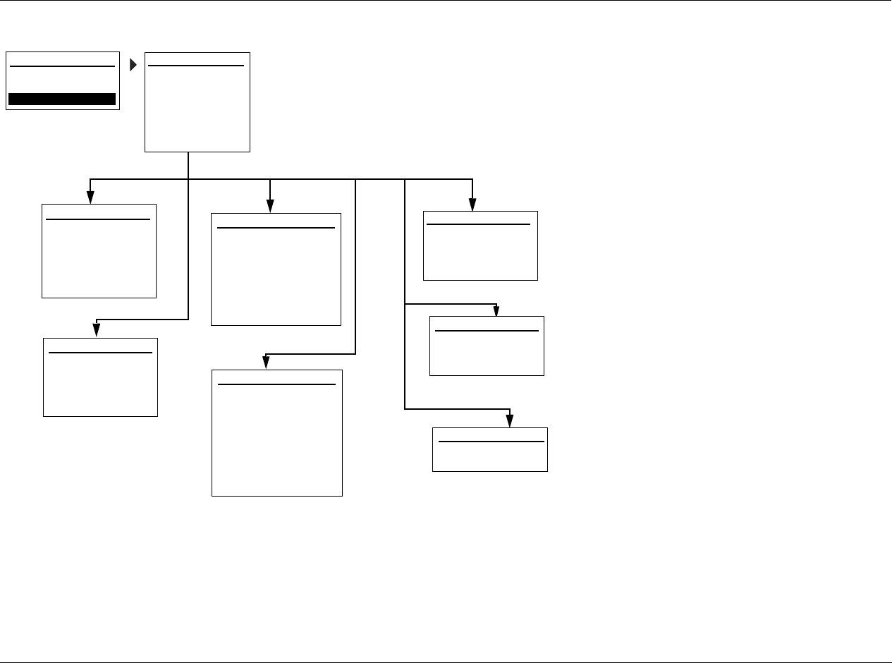
RV-5 Appendix
A-5
MAIN MENU: SETUP MENU
MAIN MENU
AUDIO CONTROLS
VIDEO CONTROLS
POWER ON SETTINGS
POWER ON VOL:
DOCK AUTO POWER:
LAST
OFF
INPUT SETUP: INPUT SETUP 1
continued on page A-6
continued on page A-8
DISPLAY SETUP
SPEAKER/EQ SETUP
INPUT SETUP
SURROUND CONFIG
DOLBY CONFIG
MUTE LEVELS
POWER ON SETTINGS
DISPLAY SETUP
DISPLAY TYPE:
ASPECT RATIO:
CONNECTION:
HDMI AUDIO OUT:
ON-SCREEN DISPLAY
FRONT PANEL DISPLAY
SETUP
continued on page A-13
continued on page A-13
SETUP
CRT
4:3
HDMI/DVI
YES
INPUT:
NAME: ________
DIG AUDIO:
ANLG AUDIO:
DIG/ANLG AUTO:
A/D SAMPLE RATE:
DVD 1
ON
HDMI 2
NONE
MODE FAMILY:
MODE:
48kHz
STEREO
2-CHANNEL
INPUT SETUP: INPUT SETUP 2
continued on page A-8
DEFAULT SUR:
VIDEO IN:
V-PROCESS:
VIDEO OUT:
HDMI LINK:
ADVANCED VIDEO
ON
BYPASS
- - -
A/V SYNC DELAY:
TRIGGER 2:
HDMI 2
0 ms
ON
ZONE 2 OUT: ANALOG
USE LAST
DVD 1
SURROUND CONFIG
LOGIC 7 DEFAULT:
DOLBY MULTI-CHANNEL
DOLBY 2.0
DTS
PCM 44.1/48kHz
PCM 96kHz
DOLBY PLii MU
DOLBY CONFIGURATION
MODE:
CENTER WIDTH:
DIMENSION:
PANORAMA:
NIGHT:
3
0
OFF
OFF
continued on page A-13
REAR SPK
SPEAKER/EQ SETUP
REAR AMP:
AUTOMATIC
AUTO EQ ONLY
MANUAL
continued on page A-13
USE LAST
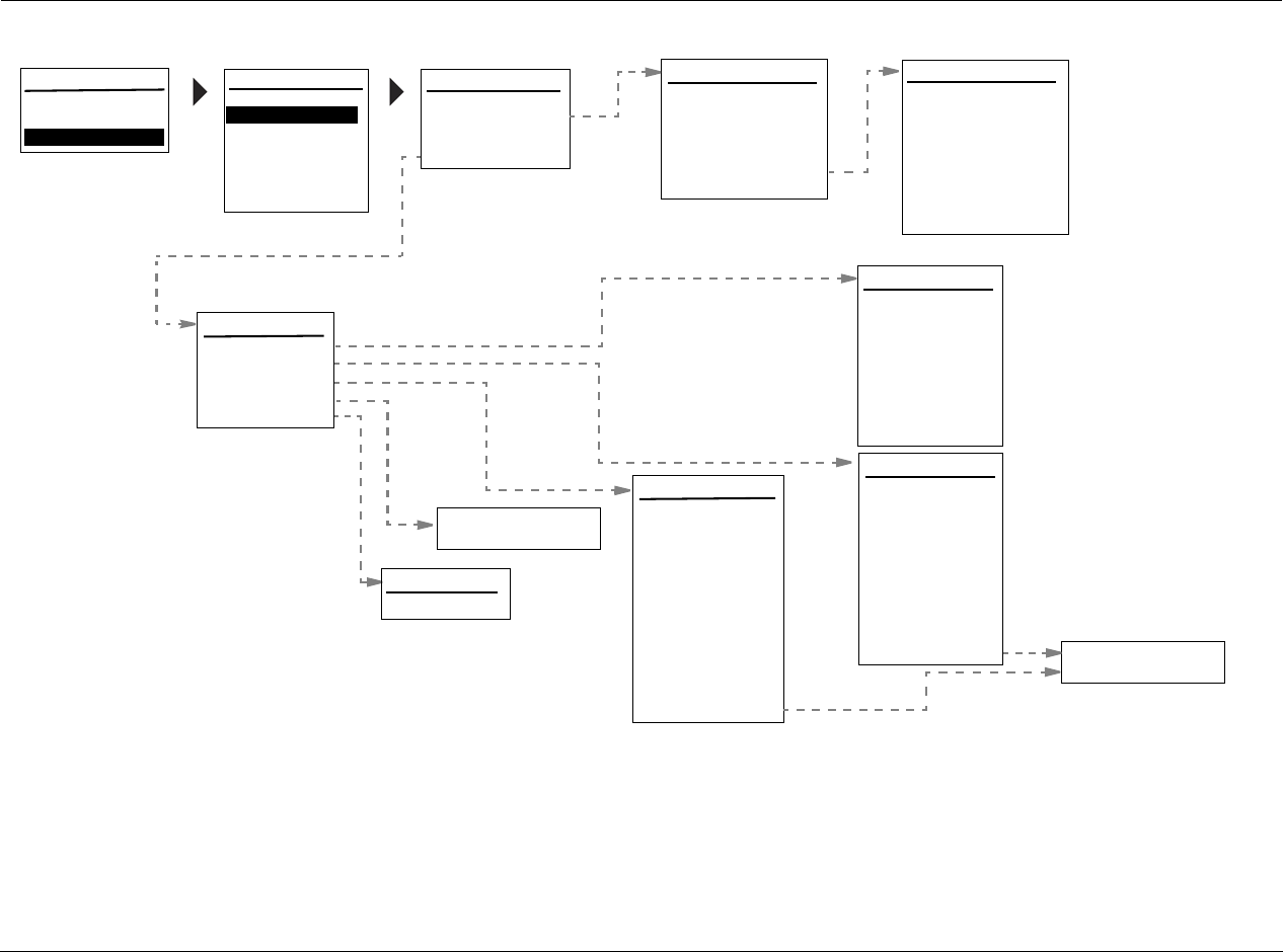
Appendix Lexicon
A-6
SETUP MENU: SPEAKERS
MAIN MENU
AUDIO CONTROLS
VIDEO CONTROLS
SETUP INPUT SETUP
SURROUND CONFIG
DOLBY CONFIG
MUTE LEVELS
POWER ON SETTINGS
SETUP
DISPLAY SETUP
SPEAKER/EQ SETUP
REAR AMP:
AUTOMATIC
AUTO EQ ONLY
MANUAL
REAR SPK
AUTOMATIC
Automatic selection of
ADJUST EQ
TILT: +0dB
OFF
SPEAKER/EQ SETUP x-over, Freq, Channel
Adjust, Delay Adjust
and Room Equalization
CONTINUE
BACK TO SPEAKER/EQ SETUP
MANUAL
SPEAKERS
SPEAKER DISTANCES
OUTPUT LEVELS
AUTO EQ:
ADJUST EQ
OFF
15
15
15
15
15
SPEAKER DISTANCES
AUTO SETTINGS:
FRONT LEFT:
CENTER:
FRONT RIGHT:
SIDE RIGHT:
REAR RIGHT:
REAR LEFT:
SIDE LEFT:
SUBWOOFERS:
OFF
80Hz
80Hz
80Hz
80Hz
80Hz
20Hz
SPEAKERS
AUTO SETTINGS:
FRONT L/R:
CENTER:
SIDE L/R:
REAR/Z2 L/R:
SUB/LFE LPF:
SUBWOOFERS:
SUB HPF:
SUB MODE: LFE ONLY
1
UNITS: FEET
RESTORE DEFAULTS
15
15
15
OFF
OUTPUT LEVELS
AUTO SETTINGS:
TEST TONE:
CENTER:
FRONT RIGHT:
SIDE RIGHT:
REAR RIGHT:
REAR LEFT:
SIDE LEFT:
SUBWOOFER1:
INPUT: ALL
RESTORE DEFAULTS
FRONT LEFT:
SUBWOOFER2:
AUTO
+0dB
+0dB
+0dB
+0dB
+0dB
+0dB
+0dB
+0dB
+0dB
ON
OFF
EZ SET DESIGN SET 1
Place mic at ear
CONTINUE FAR FIELD
BACK TO SPEAKER/EQ SETUP
ON
OFF
SKIP FAR FIELD
level near listening
position, at least
3 ft/0.9 m from any
hard surface.
Set volume to -25dB
RV-5 Appendix
A-7
PLEASE WAIT
SETUP MENU: INPUT SETUP
SETUP MENU: DISPLAY SETUP
FLESHTONE NR:
COMPNT ENHANCE:
BRIGHTNESS:
CONTRAST:
COLOR:
TEST PAT:
100
ADVANCED VIDEO 2
INPUT SETUP: INPUT SETUP 1
INPUT:
NAME: ________
DIG AUDIO:
ANLG AUDIO:
DIG/ANLG AUTO:
A/D SAMPLE RATE:
DVD
ON
HDMI 2
NONE
MODE FAMILY:
MODE:
48kHz
STEREO
2-CHANNEL
INPUT SETUP: INPUT SETUP 2
DEFAULT SUR:
VIDEO IN:
V-PROCESS:
USE LAST
USE LAST
MAIN MENU
AUDIO CONTROLS
VIDEO CONTROLS
SETUP INPUT SETUP
SURROUND CONFIG
DOLBY CONFIG
MUTE LEVELS
POWER ON SETTINGS
SETUP
SPEAKER/EQ SETUP
DISPLAY SETUP
DISPLAY SETUP
DISPLAY TYPE:
ASPECT RATIO:
CONNECTION:
HDMI AUDIO OUT:
ON-SCREEN DISPLAY
FRONT PANEL DISPLAY
CRT
4:3
HDMI/DVI
YES
ON-SCREEN DISPLAY SETUP
2-LINE OSD:
MENU TIME OUT:
OFF
50s
FRONT PANEL DISPLAY SETUP
BRIGHTNESS:
TIME OUT:
FULL
OFF
ON
100
100
OFF
ON
INPUT TYPE:
SHARPNESS:
NOISE REDUCTION:
X-COLOR SUPRESS:
DCDi INTERPOL:
FILM DETECTION:
FILM EDIT DETECT:
ON
ADVANCED VIDEO 1
32
ON
ON
ON
ON
VCR
MAIN MENU
AUDIO CONTROLS
VIDEO CONTROLS
SETUP
SURROUND CONFIG
DOLBY CONFIG
MUTE LEVELS
POWER ON SETTINGS
SETUP
SPEAKER/EQ SETUP
DISPLAY SETUP
INPUT SETUP
EDIT INPUT NAME
DVD
BUTTONS TO EDIT
UP TO 8 CHARACTERS
BUTTON TO ADVANCE
>
INPUT NAME
EDIT INPUT NAME
RESTORE DEFAULT NAME
PRESS MENU
RESTORE INPUT NAME
TO
VIDEO OUT:
HDMI LINK:
ADVANCED VIDEO
A/V SYNC DELAY:
TRIGGER 2:
ZONE-2 OUT:
HDMI 2
BYPASS
OFF
100mS
OFF
DOWNMIX
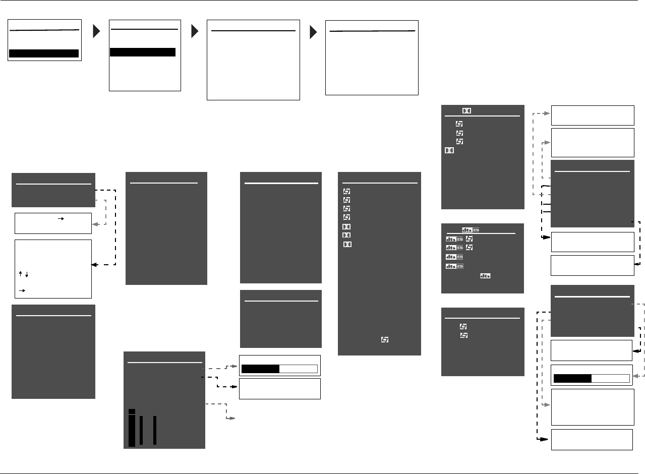
Appendix Lexicon
A-8
Selecting an INPUT SETUP menu item opens the cor-
responding menu shown below. These menus are
identical regardless of which input is selected. The
MAIN ADV menus shown on the next page indicate
factory-default parameter settings for each input.
EDIT INPUT NAME
DVD1
BUTTONS TO EDIT
UP TO 8 CHARACTERS
BUTTON TO ADVANCE
>
DVD1 INPUT NAME
EDIT INPUT NAME
RESTORE DEFAULT NAME
PRESS MENU TO
RESTORE INPUT NAME
DVD1 DIGITAL IN
COAX-1
COAX-2
COAX-3
COAX-4
DVD1 ANALOG IN
ANALOG-1
ANALOG-2
ANALOG-3
ANALOG-4
ANALOG-5
ON
OFF
DVD1 ANLG IN LVL
AUTO
RL
AUTO GAIN
ON
+0.0dB
+0.dB
MANUAL
-18 to +12dB
DVD1 VIDEO IN
COMPOSITE-1
COMPOSITE-2
COMPOSITE-3
COMPOSITE-4
COMPOSITE-5
S-VIDEO-1
S-VIDEO-2
S-VIDEO-3
S-VIDEO-4
S-VIDEO-5
DVD1 COMPONENT
COMPONENT-1
COMPONENT-2
COMPONENT-3
VIDEO
DVD1 D MODE
FILM
TV
MUSIC
DIGITAL
5.1 2-CHANNEL
5.1
5.1
5.1
5.1 MONO LOGIC
5.1 MONO SURR
5.1 MONO
HEADPHONE 5.1
DVD1 MAIN ADV
INPUT SELECT
ANALOG BYPASS
S-VIDEO 16:9
S-VIDEO OSD 4:3
COMPONENT OSD
DIGITAL
OFF
AUTO
ON
OFF
dB
0
-6
-15
-30
-45
OPTICAL-1
OPTICAL-2
OPTICAL-3
OPTICAL-4
NONE
NONE
DIGITAL
ANALOG
AUTO
AUTO
OFF
ON
OFF
DVD1 2-CH MODE
FILM
TV
MUSIC
MUSIC SURR
PLII MOVIE
PLII MUSIC
PRO LOGIC
NIGHTCLUB
CONCERT HALL
CHURCH
CATHEDRAL
PANORAMA
2-CH SURROUND
2-CHANNEL
MONO LOGIC
MONO SURROUND
MONO
HEADPHONE
NONE
TUNER
PHONO
ANALOG-8
ANALOG-6
ANALOG-7
LIVE!
The appearance of the ANALOG
IN menu depends on the configu-
ration of the analog audio input
connectors. Refer to page 3-8 for
more information.
NONE
Indicates the current amount of
analog audio input level adjust-
ment for the selected analog
audio input connector. This
parameter cannot be adjusted.
USE LAST
USE LAST
DVD1 5.1a MODE
MUSIC
HEADPHONE 5.1a
5.1a
5.1a
USE LAST
FILM
5.1 STANDARD
5.1 2-CHANNEL
LEGACY VIDEO A
A
B
DVD1 ZONE2 ADV
ANLG IN LVL
DIGITAL BYPASS
DIG OUT RATE
RECORD
+0dB
OFF
44.1kHz
ENABLED
44.1kHz
48kHz
-18 to +12dB
88.2kHz
96kHz
BLOCKED
ENABLED
ON
OFF
DVD1 MODE
FILM
MUSIC
2-CHAN
HEADPHONE
USE LAST
INPUT SETUP: INPUT SETUP 1
INPUT:
NAME: ________
DIG AUDIO:
ANLG AUDIO:
DIG/ANLG AUTO:
A/D SAMPLE RATE:
DVD
ON
HDMI 2
NONE
MODE FAMILY:
MODE:
48kHz
STEREO
2-CHANNEL
MAIN MENU
AUDIO CONTROLS
VIDEO CONTROLS
SETUP
SURROUND CONFIG
DOLBY CONFIG
MUTE LEVELS
POWER ON SETTINGS
SETUP
SPEAKER/EQ SETUP
DISPLAY SETUP
INPUT SETUP
INPUT SETUP: INPUT SETUP 2
DEFAULT SUR:
VIDEO IN:
V-PROCESS:
ZONE-2 OUT:
ADVANCED VIDEO
ON
BYPASS
A/V SYNC DELAY:
TRIGGER 2:
HDMI 2
0 ms
ANALOG
USE LASTUSE LAST
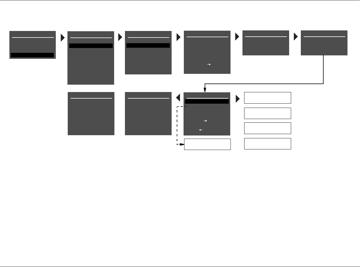
RV-5 Appendix
A-9
SPEAKER SETUP
SET CROSSOVERS
CHECK MICROPHONES
AUTOMATIC
MANUAL
SET CROSSOVERS
BEFORE CALIBRATING
(MICROPHONE)
OK
(MICROPHONE)
NOT DETECTED
(MICROPHONE)
SIGNAL TOO LOW
(MICROPHONE)
OUT OF RANGE
(MICROPHONE)
TOO MUCH ROOM NOISE
CHECK MICROPHONES
GROUP MICROPHONES
INTO A BUNDLE IN THE
MIDDLE OF THE ROOM
PRESS TO
BEGIN MIC CHECK
CHECK MICROPHONES
CHECKING FOR SILENCE
PLEASE WAIT
CHECK MICROPHONES
CHECKING MICROPHONES
PLEASE WAIT
AUTO SPEAKER SETUP
DISTANCES & LEVELS
DISTANCES
OUTPUT LEVELS
IN PRIMARY LISTENING
POSITIONS
SPEAKER SETUP
SET CROSSOVERS
CHECK MICROPHONES
AUTOMATIC
MANUAL
SET CROSSOVERS
BEFORE CALIBRATING
CHECK MICROPHONES
MIC 1
MIC 2
PRESS TO VIEW
DETAILS
PLACE MICROPHONES
ERROR
OK
or
When an ERROR message appears on the last CHECK
MICROPHONES screen, pressing the arrow but-
ton opens the SPEAKER SETUP menu. When no
ERROR message appears on the last CHECK MICRO-
PHONES screen, pressing the arrow button opens
the AUTO SPEAKER SETUP menu.
When an ERROR mes-
sage appears on the last
CHECK MICROPHONES
screen, press the or
arrow button to highlight
the desired microphone.
Then, press the arrow
button to view more
details about the error.
One of the messages
shown to the left will
appear in the on-screen
display.
or
or
or
PRESS TO CONTINUE
SETUP
INPUTS
SPEAKERS
I/O CONFIG
DISPLAYS
VOLUME CONTROLS
TRIGGER
TUNER SETUP
LOCK OPTIONS
MAIN MENU
MODE ADJUST
AUDIO CONTROLS
TUNER PRESETS
SETUP
LIVE! CALIBRATION
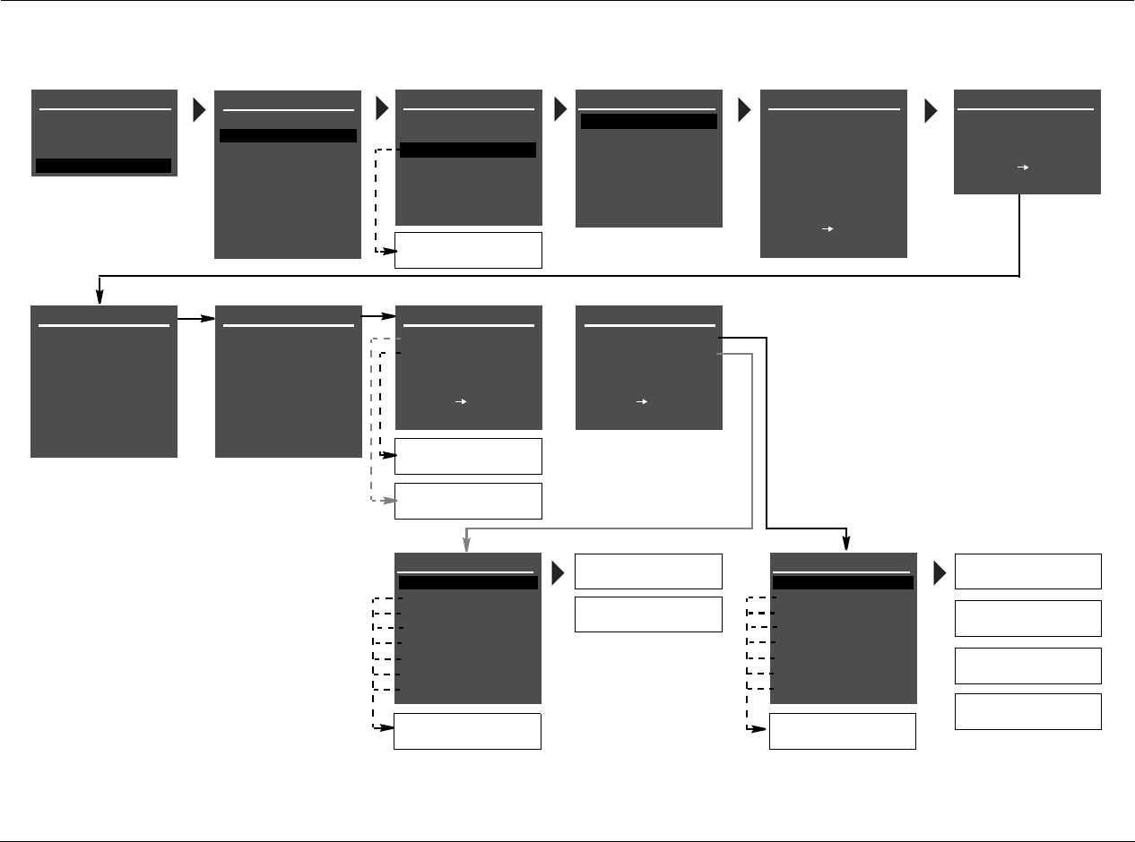
Appendix Lexicon
A-10
SETUP MENU: SPEAKERS
(continued)
CUSTOM SETUP
40 Hz
60 Hz
60 Hz
60 Hz
40 Hz
OFF
N/A
APART
AUTO SPEAKER SETUP
!CAUTION!
HIGH AUDIO LEVELS
YOU WILL HAVE 10 SEC
TO LEAVE THE ROOM OR
SIT QUIETLY
PRESS TO BEGIN
COUNTDOWN
AUTO LEVELS
FRONT LEFT
CENTER
FRONT RIGHT
SIDE RIGHT
REAR RIGHT
REAR LEFT
SIDE LEFT
SUBWOOFER
ERROR
+0.0dB
+0.0dB
+0.0dB
+0.0dB
+0.0dB
+0.0dB
+0.0dB
AUTO DISTANCES
FOR AUTO CALIBRATION
SPEAKER SETUP
SET CROSSOVERS
CHECK MICROPHONES
AUTOMATIC
MANUAL
SET CROSSOVERS
BEFORE CALIBRATING
MIC CHECK REQUIRED
or
CUSTOM SETUP
AUTO SPEAKER SETUP
DISTANCES
LEVELS
AUTO VALUES APPLIED
PRESS TO VIEW
DETAILS
AUTO SPEAKER SETUP
DISTANCES & LEVELS
DISTANCES
OUTPUT LEVELS
PLACE MICROPHONES
AROUND PREFERRED
LISTENING POSITIONS
AUTO SPEAKER SETUP
TEST WILL BEGIN IN
10
PRESS TO SKIP
COUNTDOWN
CUSTOM SETUP
SETTING DISTANCES
FRONT LEFT
CENTER
FRONT RIGHT
SIDE RIGHT
REAR RIGHT
REAR LEFT
SIDE LEFT
SUBWOOFER
0.0ft
0.0ft
0.0ft
0.0ft
0.0ft
0.0ft
0.0ft
0.0ft
CUSTOM SETUP
SETTING LEVELS
FRONT LEFT
CENTER
FRONT RIGHT
SIDE RIGHT
REAR RIGHT
REAR LEFT
SIDE LEFT
SUBWOOFER
+0.0dB
+0.0dB
+0.0dB
+0.0dB
+0.0dB
+0.0dB
+0.0dB
+0.0dB
CUSTOM SETUP
AUTO SPEAKER SETUP
DISTANCES
LEVELS
AUTO VALUES APPLIED
PRESS TO VIEW
DETAILS
OK
OK
ERROR
ERROR
OK
LEVELS
OK
DISTANCES
OK
(SPEAKER)
SPKR OUTPUT TOO HIGH
(SPEAKER)
SPKR OUTPUT TOO LOW
(SPEAKER)
FRONT LEFT
CENTER
FRONT RIGHT
SIDE RIGHT
REAR RIGHT
REAR LEFT
SIDE LEFT
SUBWOOFER
ERROR
0.0ft
0.0ft
0.0ft
0.0ft
0.0ft
0.0ft
0.0ft
OK
(SPEAKER)
SPEAKER OUT OF PHASE
(SPEAKER)
SIGNAL TOO LOW
(SPEAKER)
MAY NOT BE ACCURATE
(SPEAKER)
UNABLE TO CALCULATE
(SPEAKER)
The AUTO DISTANCES and AUTO LEVELS screens
shown on the right indicate the individual calibra-
tion results for each speaker. Press the and
arrow buttons to highlight the desired speaker cali-
bration parameter. Then, press the arrow but-
ton to view more detailed results for the selected
speaker.
Press the arrow button to return to the AUTO
SPEAKER SETUP results screen shown above (right).
Then, press the arrow button to select the other
calibration procedure or press the arrow button
to return to the SPEAKER SETUP menu.
When the RV-8 is finished calibrating speaker dis-
tances and output levels, the AUTO SPEAKER
SETUP results screen shown at the left will open in
the on-screen display, indicating the results for
each calibration procedure. Press the or
arrow button to highlight the desired calibration
procedure. Then, press the arrow button to
select this procedure. Selecting DISTANCES opens
the AUTO DISTANCES screen shown below.
Selecting the LEVELS option opens the AUTO LEV-
ELS screen shown below.
SETUP
INPUTS
SPEAKERS
I/O CONFIG
DISPLAYS
VOLUME CONTROLS
TRIGGER
TUNER SETUP
LOCK OPTIONS
MAIN MENU
MODE ADJUST
AUDIO CONTROLS
TUNER PRESETS
SETUP
LIVE! CALIBRATION
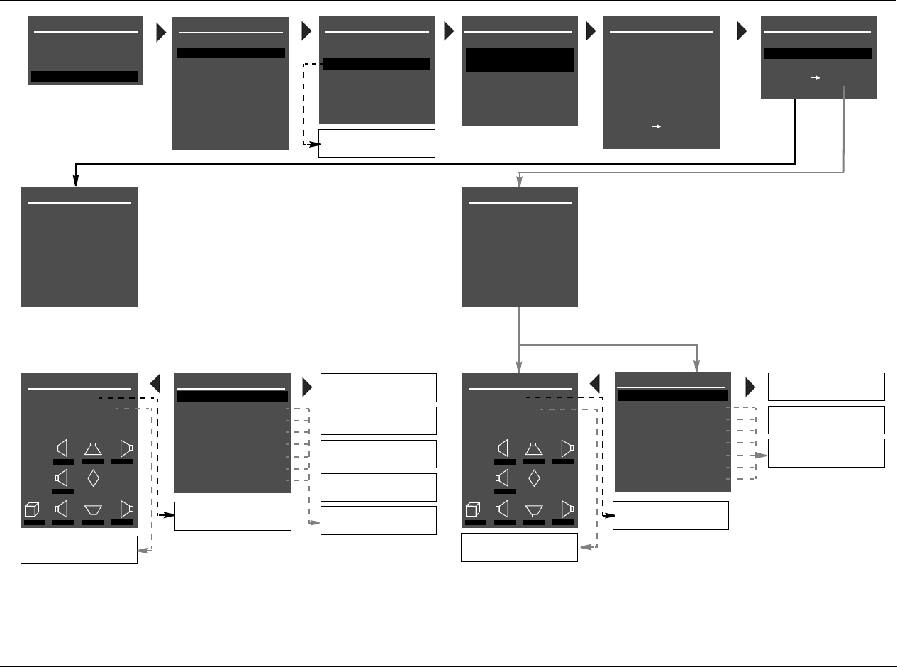
RV-5 Appendix
A-11
AUTO SPEAKER SETUP
AUTO LEVELS
FRONT LEFT
CENTER
FRONT RIGHT
SIDE RIGHT
REAR RIGHT
REAR LEFT
SIDE LEFT
SUBWOOFER
ERROR
+0.0dB
+0.0dB
+0.0dB
+0.0dB
+0.0dB
+0.0dB
+0.0dB
AUTO DISTANCES
FOR AUTO CALIBRATION
SPEAKER SETUP
SET CROSSOVERS
CHECK MICROPHONES
AUTOMATIC
MANUAL
SET CROSSOVERS
BEFORE CALIBRATING
MIC CHECK REQUIRED
DISTANCES & LEVELS
DISTANCES
OUTPUT LEVELS
PLACE MICROPHONES
AROUND PREFERRED
LISTENING POSITIONS
CUSTOM SETUP
40 Hz
60 Hz
60 Hz
60 Hz
40 Hz
OFF
N/A
APART
AUTO SPEAKER SETUP
!CAUTION!
HIGH AUDIO LEVELS
YOU WILL HAVE 10 SEC
TO LEAVE THE ROOM OR
SIT QUIETLY
PRESS TO BEGIN
COUNTDOWN
AUTO SPEAKER SETUP
TEST WILL BEGIN IN
10
PRESS TO SKIP
COUNTDOWN
CUSTOM SETUP
SETTING DISTANCES
FRONT LEFT
CENTER
FRONT RIGHT
SIDE RIGHT
REAR RIGHT
REAR LEFT
SIDE LEFT
SUBWOOFER
0.0ft
0.0ft
0.0ft
0.0ft
0.0ft
0.0ft
0.0ft
0.0ft
CUSTOM SETUP
SETTING LEVELS
FRONT LEFT
CENTER
FRONT RIGHT
SIDE RIGHT
REAR RIGHT
REAR LEFT
SIDE LEFT
SUBWOOFER
+0.0dB
+0.0dB
+0.0dB
+0.0dB
+0.0dB
+0.0dB
+0.0dB
+0.0dB
SPKR OUTPUT TOO HIGH
(SPEAKER)
SPKR OUTPUT TOO LOW
(SPEAKER)
FRONT LEFT
CENTER
FRONT RIGHT
SIDE RIGHT
REAR RIGHT
REAR LEFT
SIDE LEFT
SUB (MONO)
ERROR
0.0ft
0.0ft
0.0ft
0.0ft
0.0ft
0.0ft
0.0ft
APPLIED
AUTO LEVELS
SPEAKER OUT OF PHASE
(SPEAKER)
SIGNAL TOO LOW
(SPEAKER)
MAY NOT BE ACCURATE
(SPEAKER)
UNABLE TO CALCULATE
(SPEAKER)
OK
(SPEAKER)
The AUTO DISTANCES screen shown below indicates
the individual calibration results for each speaker. Press
the and arrow buttons to highlight the desired
speaker calibration parameter. Then, press the
arrow button to view more detailed results for the
selected speaker.
The AUTO LEVELS screen shown below indicates the
individual calibration results for each speaker. Press the
and arrow buttons to highlight the desired
speaker calibration parameter. Then, press the
arrow button to view more detailed results for the
selected speaker.
OK
(SPEAKER)
SET DISTANCES
AUTO DISTANCES
ORIGINAL DISTANCES
C
R SR RR
L SL RL
M
SUB
0.0ft 0.0ft 0.0ft
0.0ft
0.0ft 0.0ft 0.0ft 0.0ft
SET LEVELS
AUTO LEVELS
ORIGINAL LEVELS
C
R SR RR
L SL RL
M
SUB
0.0dB 0.0dB 0.0dB
0.0dB
0.0dB 0.0dB 0.0dB 0.0dB
APPLIED
ORIGINAL LEVELS
APPLIED
AUTO DISTANCES
APPLIED
ORIGINAL DISTANCES
SETUP
INPUTS
SPEAKERS
I/O CONFIG
DISPLAYS
VOLUME CONTROLS
TRIGGER
TUNER SETUP
LOCK OPTIONS
MAIN MENU
MODE ADJUST
AUDIO CONTROLS
TUNER PRESETS
SETUP
LIVE! CALIBRATION
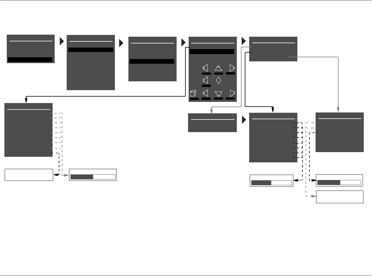
Appendix Lexicon
A-12
SETUP MENU: SPEAKERS
(continued)
75 to 120dB
ON
OFF
SPEAKER LEVEL ADJUST
FRONT LEFT
CENTER
FRONT RIGHT
SIDE RIGHT
REAR RIGHT
REAR LEFT
SIDE LEFT
SUBWOOFER
+0.0dB
+0.0dB
+0.0dB
+0.0dB
+0.0dB
+0.0dB
+0.0dB
+0.0dB
MANUAL SPEAKER SETUP
SPEAKER DISTANCES
LEVELS CALIBRATION
C
R SR RR
L SL RL
M
SUB
40Hz 60Hz 60Hz
60Hz
40Hz 40Hz 60Hz 60Hz
LEVELS CALIBRATION
INTERNAL NOISE TEST
EXTERNAL NOISE TEST
BASS PEAK LIMITER
-18 to 12dB
BASS PEAK LIMITER
CAL NOISE
SUB LIMITER
LIMIT ADJ
!CAUTION!
HIGH AUDIO LEVELS
ON
ON
100dB
INTERNAL NOISE
!CAUTION!
HIGH AUDIO LEVELS
CUSTOM SETUP
SPEAKER DISTANCES
FRONT LEFT
CENTER
FRONT RIGHT
SIDE RIGHT
REAR RIGHT
REAR LEFT
SIDE LEFT
SUBWOOFER
UNITS
0.0ft
0.0ft
0.0ft
0.0ft
0.0ft
0.0ft
0.0ft
0.0ft
FEET
METERS 0.0 to 30.0ft or 12.0m
SPEAKER SETUP
SET CROSSOVERS
CHECK MICROPHONES
AUTOMATIC
MANUAL
SET CROSSOVERS
BEFORE CALIBRATING
FEET
SETUP
INPUTS
SPEAKERS
I/O CONFIG
DISPLAYS
VOLUME CONTROLS
TRIGGER
TUNER SETUP
LOCK OPTIONS
MAIN MENU
MODE ADJUST
AUDIO CONTROLS
TUNER PRESETS
SETUP
LIVE! CALIBRATION

RV-5 Appendix
A-13
SETUP MENU: MUTE LEVELS
MAIN MENU
AUDIO CONTROLS
VIDEO CONTROLS
SETUP INPUT SETUP
SURROUND CONFIG
DOLBY CONFIG
POWER ON SETTINGS
SETUP
SPEAKER/EQ SETUP
DISPLAY SETUP
MUTE LEVELS
MAIN ZONE: -30dB
MUTE LEVELS
ZONE 2: -30dB
SETUP MENU: POWER ON SETTINGS
MAIN MENU
AUDIO CONTROLS
VIDEO CONTROLS
SETUP INPUT SETUP
SURROUND CONFIG
DOLBY CONFIG
SETUP
SPEAKER/EQ SETUP
DISPLAY SETUP
MUTE LEVELS
POWER ON VOL: -30dB
POWER ON SETTINGS
DOCK AUTO POWER: OFF
POWER ON SETTINGS
SETUP MENU: DOLBY CONFIG
MAIN MENU
AUDIO CONTROLS
VIDEO CONTROLS
SETUP INPUT SETUP
SURROUND CONFIG
POWER ON SETTINGS
SETUP
SPEAKER/EQ SETUP
DISPLAY SETUP
MUTE LEVELS
MODE:
0
DOLBY CONFIG
CENTER WIDTH:
DOLBY PLII MU
SETUP MENU: SURROUND CONFIG
MAIN MENU
AUDIO CONTROLS
VIDEO CONTROLS
SETUP INPUT SETUP
DOLBY CONFIG
POWER ON SETTINGS
SETUP
SPEAKER/EQ SETUP
DISPLAY SETUP
MUTE LEVELS
LOGIC 7 DEFAULT: ON
SURROUND CONFIG
DOLBY MULTI-CHANNEL
DOLBY CONFIG
DIMENSION:
PANORAMA:
3
OFF
NIGHT: OFF
SURROUND CONFIG
DOLBY VIRTUAL:
STEREO DOWNMIX:
DOLBY MULTI-CHANNEL
LOGIC 7:
ON
ON
ON
DOLBY 2.0
DTS
PCM 44.1/48 kHz
PCM 96 kHz
LOGIC 7:
DOLBY PLIIx:
PCM 44.1/48 kHz
DOLBY PLII:
ON
ON
ON
DOLBY VIRTUAL:
HALL:
DTS NEO:6:
ON
ON
ON
5/7 CH STEREO: ON
LOGIC 7:
DOLBY PLIIx:
PCM 96 kHz
DOLBY PLII:
ON
ON
ON
DTS NEO:6: ON
5/7 CH STEREO: ON
DTS 96/24:
DTS-ES MATRIX:
DTS
DTS + NEO:6:
ON
ON
ON
DTS-ES DISCRETE:
STEREO DOWNMIX:
LOGIC 7:
ON
ON
ON
DOLBY PLIIx:
DOLBY 2.0
DOLBY PLII:
ON
ON
DOLBY VIRTUAL:
LOGIC 7: ON
ON
FACTORY SETTINGS
EXIT
RESTORE DEFAULTS FACTORY SETTINGS
HAVE BEEN RESTORED
PRESS ANY KEY
TO RESTART
Refer to the Restoring Factory-Default Settings section
that begins on page 7-4 for more information.
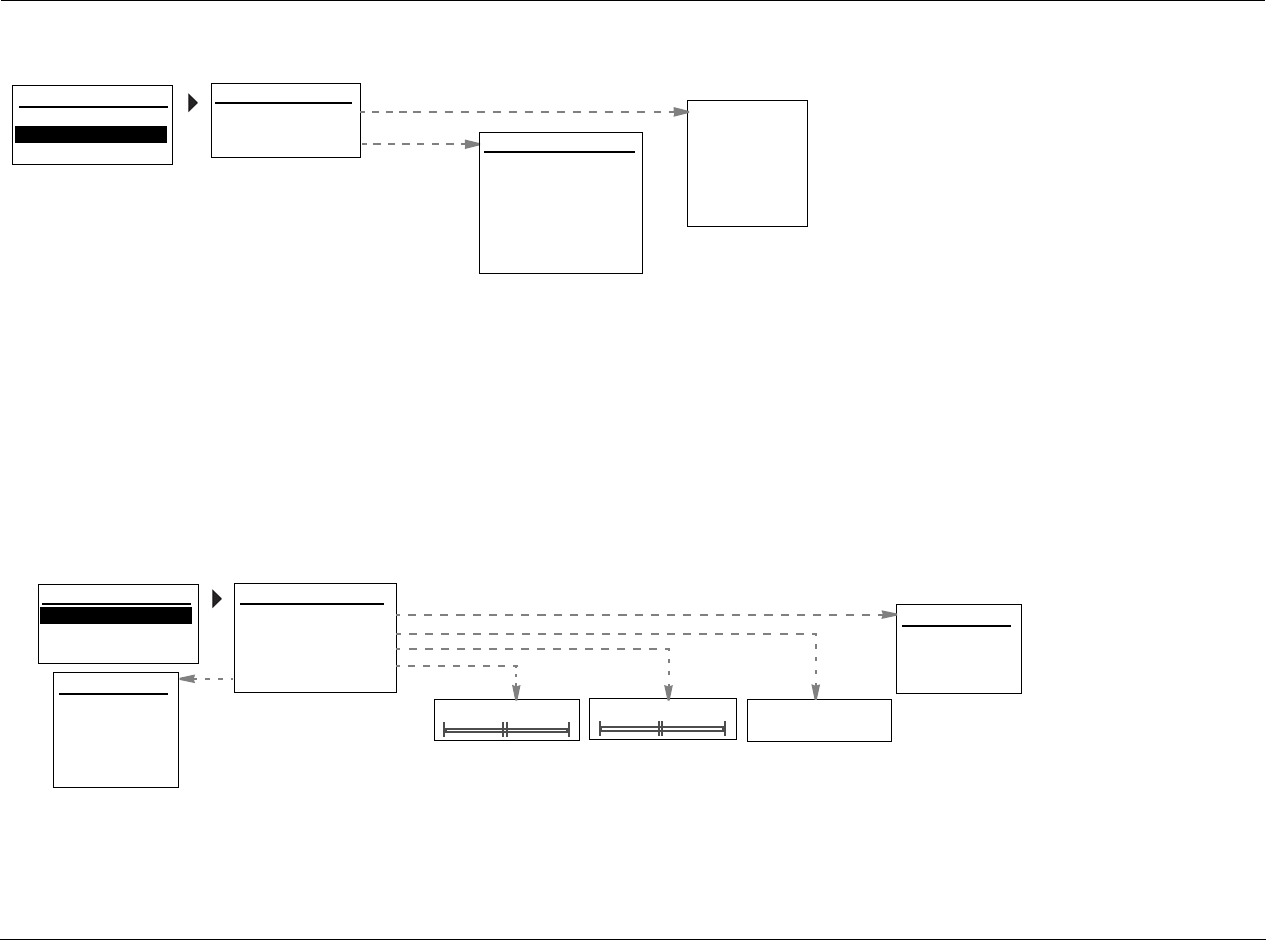
Appendix Lexicon
A-14
LB ZOOM
MAIN MENU: VIDEO CONTROLS
ON
OFF
AUDIO CONTROLS
EQ PRESET
TONE CONTROLS
BASS
TREBLE
AUDIO STATUS
OFF
+0.0dB
-6.0 to +6.0dB
-6.0 to +6.0dB
MAIN MENU: AUDIO CONTROLS
MAIN MENU
AUDIO CONTROLS
VIDEO CONTROLS
4:3 IN>16:9 DISPLAY
VIDEO STATUS
ORIGINAL
SETUP
VIDEO CONTROLS
INPUT RESOL:
VIDEO PROCESS:
OUTPUT RESOL:
COMPONENT OUT:
S-VIDEO OUT:
COMPOSITE OUT:
BYPASS
VIDEO STATUS
COPY PROTECTION:
AUTO
STRETCH
2.35 LB ZOOM
STRETCH 2
2.35 LB STRETCH
OFF
- - -
480i
OFF
OFF
- - -
MAIN MENU
AUDIO CONTROLS
VIDEO CONTROLS
SETUP
+0.0dB
EQ PRESET
PRESET 1: BYPASS
ACTIVE PS: USER
PRESET 2: BYPASS
PRESET 3: BYPASS
AUDIO STATUS
INPUT:
MODE FAMILY:
AUDIO:
NAME:
MODE:
CONNECTOR:
ORIGINAL
RV-5 Appendix
A-15
MAIN MENU: MODE ADJUST
MAIN MENU
MODE ADJUST
AUDIO CONTROLS
TUNER PRESETS
* These listening mode
names differ depend-
ing on the current
input source, speaker
setup and parameter
settings. Refer to the
Listening Mode
Descriptions for more
information.
SETUP
ON
OFF
MODE ADJUST
5.1a BYPASS OFF
2CH BYPASS OFF
HEADPHONE OFF
HEADPHONE 5.1 OFF
HEADPHONE OFF
HEADPHONE 5.1a OFF
LIVE! SMALL OFF
LIVE! MED OFF
LIVE! LARGE OFF
MODE ADJUST
FILM OFF
TV OFF
MUSIC OFF
MUSIC SURR OFF
PLIIx MOV* OFF
PLIIx MUS* OFF
PLII MOVIE OFF
PLII MUSIC OFF
PRO LOGIC OFF
CIN OFF
MUSIC OFF
NIGHTCLUB OFF
CONCERT HHALL OFF
CHURCH OFF
CATHEDRAL OFF
PANORAMA OFF
2-CH SURROUND OFF
2-CHANNEL OFF
MONO LOGIC OFF
MONO SURROUND OFF
MONO OFF
5.1 FILM OFF
5.1 TV OFF
5.1 MUSIC OFF
5.1 PLIIx MOV* OFF
5.1 PLIIx MUS* OFF
DIGITAL EX* OFF
5.1 2-CHANNEL OFF
5.1 MONO LOGIC OFF
5.1 MONO SURR OFF
5.1 MONO OFF
FILM* OFF
MUSIC* OFF
*OFF
2-CHAN* OFF
5.1a FILM OFF
5.1a MUSIC OFF
5.1a STANDARD OFF
5.1a 2-CHANNEL OFF
FILM
AUTO AZIMUTH
VOCAL ENHANCE
RE-EQUALIZER
ON
+0.0dB
ON
REARSOUND STAGE
5 SPKR ENHANCE
BASS ENHANCE
SURR ROLLOFF
REAR DLY OFFSET
OUTPUT LEVELS
CUSTOM
ON
OFF
7.0kHz
15ms
TV
AUTO AZIMUTH
VOCAL ENHANCE
FRONT STEERING
ON
+0.0dB
FILM
OFFRE-EQUALIZER
SOUND STAGE
5 SPKR ENHANCE
BASS ENHANCE
SURR ROLLOFF
REAR DLY OFFSET
OUTPUT LEVELS
REAR
ON
OFF
7.0kHz
15ms
CUSTOM
MUSIC
VOCAL ENHANCE
FRONT STEERING
SOUND STAGE
+0.0dB
MUSIC
NEUTRAL
ON5 SPKR ENHANCE
BASS ENHANCE
SURR ROLLOFF
REAR DLY OFFSET
OUTPUT LEVELS
CUSTOM
OFF
7.0kHz
15ms
MUSIC SURR
VOCAL ENHANCE
SOUND STAGE
BASS ENHANCE
SURR ROLLOFF
REAR DLY OFFSET
OUTPUT LEVELS
CUSTOM
5 SPKR ENHANCE
+0.0dB
NEUTRAL
ON
FRONT STEERING MSURR
OFF
7.0kHz
15ms
OUTPUT LEVELS
CUSTOM
PLIIx MOV
PANORAMA
DIMENSION
OFF
CTR WIDTH
PLIIx MUS
SURROUND DLY
OUTPUT LEVELS
CUSTOM
3
NEUTRAL
10ms
OUTPUT LEVELS
CUSTOM
PRO LOGIC
OUTPUT LEVELS
CUSTOM
MUSIC
NIGHTCLUB
CENTER DEPTH
SIZE
PRE-DELAY
ROLLOFF
EFFECT LVL
OUTPUT LEVELS
CUSTOM
LIVENESS
11
5m
196ms
SPEECH DETECT ON
5ms
9.0kHz
+3dB
CONCERT HALL
CENTER DEPTH
SIZE
PRE-DELAY
ROLLOFF
EFFECT LVL
OUTPUT LEVELS
CUSTOM
LIVENESS
12
20m
1.72ms
SPEECH DETECT ON
OFF
2.4kHz
-2dB
OUTPUT LEVELS
CUSTOM
CIN
CHURCH
CENTER DEPTH
SIZE
PRE-DELAY
ROLLOFF
EFFECT LVL
OUTPUT LEVELS
CUSTOM
MID RT
5
20m
1.56s
SPEECH DETECT ON
1.87s
24ms
2.4kHz
-3dB
BASS RT
CATHEDRAL
CENTER DEPTH
SIZE
BASS RT
PRE-DELAY
ROLLOFF
EFFECT LVL
OUTPUT LEVELS
MID RT
12
30m
3.72s
SPEECH DETECT ON
4.47s
23ms
3.1kHz
CUSTOM
-8dB
PANORAMA
EFFECT LVL
LOW FREQ WIDTH
REAR DLY OFFSET
INPUT BALANCE
CALIBRATION
OUTPUT LEVELS
CUSTOM
SURR ROLLOFF
+4dB
+0
3.1kHz
BASS CONTENT STEREO
15ms
<l>
PLII MOVIE
OUTPUT LEVELS
CUSTOM
PLII MUSIC
PANORAMA OFF
CTR WIDTH 3
DIMENSION NEUTRAL
SURROUND DLY 10ms
OUTPUT LEVELS
CUSTOM
OUTPUT LEVELS
CUSTOM
2-CH SURROUND
SUB LEVEL
CUSTOM
2-CHANNEL
+0dB
OUTPUT LEVELS
CUSTOM
MONO SURROUND
EFFECT LVL
ACADMY FILTER
MONO LOGIC
SURR ROLLOFF
OUTPUT LEVELS
CUSTOM
-9dB
ON
3.1kHz
SUB LVL
CUSTOM
MONO
+0dB
Appendix Lexicon
A-16
2-CHAN
CENTER MIX
CNTR DLY SAMPLES
LFE MIX
MASTER LEVEL
+0dB
+0
SURROUND MIX +0dB
SUB L/R LVL
CUSTOM
+0dB
+0.0dB
+0dB
AUTO
DECODING
5.1a FILM
VOCAL ENHANCE +0.0dB
RE-EQUALIZER ON
SOUND STAGE NEUTRAL
5 SPKR ENHANCE ON
BASS ENHANCE OFF
SURR ROLLOFF 7.0kHz
REAR DLY OFFSET 15ms
LFE MIX +0.0dB
OUTPUT LEVELS
CUSTOM
5.1a MUSIC
VOCAL ENHANCE +0.0dB
FRONT STEERING MUSIC
RE-EQUALIZER ON
SOUND STAGE NEUTRAL
5 SPKR ENHANCE ON
BASS ENHANCE OFF
SURR ROLLOFF 7.0kHz
REAR DLY OFFSET 15ms
LFE MIX +0.0dB
OUTPUT LEVELS
CUSTOM
CUSTOM
OUTPUT LEVELS
5.1a STANDARD
DECODING
OUTPUT LEVELS
LFE MIX
CUSTOM
+0.0dB
AUTO
LIVE! SMALL
MID RT 597ms
BASS RT 597ms
ROLLOFF 3.1kHz
TREB CUT RT 3.1kHz
PRE DELAY 10ms
ADVANCED
CUSTOM
5.1 PLIIx MOV
EX DECODING AUTO
COMPRESSION OFF
LFE MIX +0.0dB
OUTPUT LEVELS
CUSTOM
5.1 PLIIx MUS
EX DECODING AUTO
COMPRESSION OFF
LFE MIX +0.0dB
OUTPUT LEVELS
CUSTOM
LIVE! SMALL ADVANCED
REVERB LVL +0dB
EARLY RFLX LVL -13dB
BASS XOVER 156Hz
SHAPE 0
SPREAD 0%
SIZE 19m
LIVE! MED ADVANCED
REVERB LVL -4dB
EARLY RFLX LVL -14dB
BASS XOVER 156Hz
SHAPE 2
SPREAD 25%
SIZE 30m
LIVE! LARGE ADVANCED
REVERB LVL -6dB
EARLY RFLX LVL -17dB
BASS XOVER 156Hz
SHAPE 2
SPREAD 28%
SIZE 38m
LIVE! MED
MID RT 1.84s
BASS RT 2.76s
ROLLOFF 2.4kHz
TREB CUT RT 3.1kHz
PRE DELAY 18ms
ADVANCED
CUSTOM
LIVE! LARGE
MID RT 4.71s
BASS RT 4.71s
ROLLOFF 3.1kHz
TREB CUT RT 2.4kHz
PRE DELAY 20ms
ADVANCED
CUSTOM
5.1 FILM
VOCAL ENHANCE +0.0dB
RE-EQUALIZER ON
SOUND STAGE REAR
5 SPKR ENHANCE ON
BASS ENHANCE OFF
SURR ROLLOFF 7.0kHz
REAR DLY OFFSET 15ms
COMPRESSION OFF
LFE MIX +0.0dB
OUTPUT LEVELS
CUSTOM
5.1 TV
VOCAL ENHANCE +0.0dB
FRONT STEERING FILM
RE-EQUALIZER OFF
SOUND STAGE REAR
5 SPKR ENHANCE ON
BASS ENHANCE OFF
SURR ROLLOFF 7.0kHz
REAR DLY OFFSET 15ms
COMPRESSION OFF
LFE MIX +0.0dB
OUTPUT LEVELS
CUSTOM
5.1 MUSIC
VOCAL ENHANCE +0.0dB
FRONT STEERING MUSIC
RE-EQUALIZER OFF
SOUND STAGE NEUTRAL
5 SPKR ENHANCE ON
BASS ENHANCE OFF
SURR ROLLOFF 7.0kHz
REAR DLY OFFSET 15ms
COMPRESSION OFF
LFE MIX +0.0dB
OUTPUT LEVELS
CUSTOM
FILM
VOCAL ENHANCE +0.0dB
RE-EQUALIZER ON
SOUND STAGE REAR
5 SPKR ENHANCE ON
BASS ENHANCE OFF
SURR ROLLOFF 7.0kHz
REAR DLY OFFSET 15ms
LFE MIX +0.0dB
DECODING AUTO
OUTPUT LEVELS
CUSTOM
MUSIC
VOCAL ENHANCE +0.0dB
FRONT STEERING MUSIC
RE-EQUALIZER OFF
SOUND STAGE NEUTRAL
5 SPKR ENHANCE ON
BASS ENHANCE OFF
SURR ROLLOFF 7.0kHz
REAR DLY OFFSET 15ms
LFE MIX +0.0dB
DECODING AUTO
OUTPUT LEVELS
CUSTOM
DIGITAL EX
EX DECODING AUTO
COMPRESSION OFF
LFE MIX +0.0dB
OUTPUT LEVELS
CUSTOM
5.1 2-CHANNEL
CENTER MIX +0dB
SURROUND MIX +0dB
CNTR DLY SAMPLES +0
MASTER LEVEL +0dB
COMPRESSION OFF
LFE MIX +0.0dB
SUB LEVEL +0dB
CUSTOM
5.1 MONO LOGIC
EFFECT LVL +-9dB
ACADEMY FI8LTER +ON
SURR ROLLOFF 3.1kHz
OUTPUT LEVELS
CUSTOM
5.1 MONO SURR
OUTPUT LEVELS
CUSTOM
5.1 MONO
SUB LEVEL +0dB
CUSTOM
5.1a 2-CHANNEL
CENTER MIX +0dB
SURROUND MIX +0dB
CNTR DLY SAMPLES +0
MASTER LEVEL+0dBLFE LFE
MIX +0.0dB
SUB LEVEL +0dB
CUSTOM
CUSTOM
OUTPUT LEVELS
5.1a BYPASS
NO PARAMETERS
2CH BYPASS
HEADPHONES
NO PARAMETERS
HEADPHONES 5.1
NO PARAMETERS
HEADPHONES
NO PARAMETERS
HEADPHONES 5.1a
NO PARAMETERS
RV-5 Appendix
A-17
MODE ADJUST (continued)
Selecting the listening mode menu CALIBRATION, OUTPUT LEVELS or CUSTOM option opens the corresponding menu path shown below. The CALIBRATION option is available for
the PANORAMA listening mode. The OUTPUT LEVELS and CUSTOM options are available for most listening modes. These menus are identical regardless of which listening mode is
selected. Listening mode menu parameter drop-down menus are shown below and on the next page.
Selecting a listening mode menu parameter opens the corresponding parameter drop-down menu shown below and on the next page. These drop-down menus are identical
regardless of which listening mode is selected. However, certain parameter ranges differ from listening mode to listening mode.
PANORAMA CALIBRATION
SOURCE
SPEAKER ANGLE
LISTENER POS
NOTE:
ENSURE THAT
“SPEAKER SETUP” HAS
BEEN PROPERLY
PERFORMED
LEFT & RIGHT
30deg
+0
PANORAMA
EFFECT LVL +4dB
STEREO
+0
3.1kHz
15ms
<I>
BASS CONTENT
LOW FREQ WIDTH
SURR ROLLOFF
REAR DLY OFFSET
INPUT BALANCE
OUTPUT LEVELS
CUSTOM
MONO LOGIC
EFFECT LVL -9dB
ON
3.1kHz
3.1kHz
ACADMY FILTER
SURR ROLLOFF
CUSTOM
OUTPUT LEVELS
CENTER +0dB
+0dB
+0dB
+0dB
SIDE L/R
REAR L/R
SUB
MONO LOGIC
EFFECT LVL -9dB
ON
+0
3.1kHz
ACADMY FILTER
SURR ROLLOFF
OUTPUT LEVELS
CUSTOM
CUSTOM VS PRESET
RESET MODE
CALIBRATION
OUTPUT LEVELS
CUSTOM
-25 to +5dB
0 to 18
CENTER MIX
CENTER DEPTH
OFF, -30 to +12dB
CENTER 5 SPKR ENHANCE
ACADEMY FILTER
AUTO AZIMUTH
ON
OFF
ON
OFF
ON
OFF
5ms to 48.6s
BASS RT
BASS CONTENT
BASS ENHANCE
ON
OFF
BINAURL
MONO
STEREO
-127 to +127
CTR WIDTH
CNTR DLY SAMPLES
COMPRESSION
AUTO
ON
OFF
MIN,1 to 6, MAX
DIMENSION
CUSTOM VS PRESET
PRESET
CUSTOM
FRONT
NEUTRAL
REAR
-12 to +6dB
EFFECT LVL FRONT STEERING
EX DECODING
AUTO
ON
OFF
DECODING
AUTO
ON
OFF
OFF
MSURR
MUSIC
FILM
Appendix Lexicon
A-18
OFF, 1 to 100ms
PRE-DELAY
OFF, 1 to 30ms
10 to 90deg
-20.0 or -10.0 to +0.0dB OFF, -30 to 12dB
4 to 20 or 30ms
30ms to 20.2s
-25 to +25
-5 to +5dB
24ms to 24.3s
500Hz to 20.0kHz, OFF
REAR L/R
SIZE
CENTER MIX
SPEAKER ANGLE VOCAL ENHANCE
LFE MIX
INPUT BALANCE
+6.0dB
+3.0dB
+0.0dB
SOURCE
RIGHT
LEFT & RIGHT
LEFT
SOUND STAGE
FRONT
NEUTRAL
REAR
ROLLOFF
REAR DLY OFFSET
PANORAMA
ON
OFF
RE-EQUALIZER
ON
OFF
MID RT
MASTER LEVEL
LOW FREQ WIDTH
LIVENESS
L< <l> >R
+5 to +5dB
SURROUND MIX
OFF, -30 to 12dB
SIDE L/R
-127 +0 +127
RESET MODE
PRESS RIGHT
TO RESTORE MODE
SURROUND EX
AUTO
ON
OFF
0 to 15ms
SURROUND DLY
500Hz to 20.0kHz, OFF
SURR ROLLOFF
OFF, -30 to 12dB
SUB LEVEL
OFF, -30 to 12dB
SUB L/R LVL
SPEECH DETECT
ON
OFF
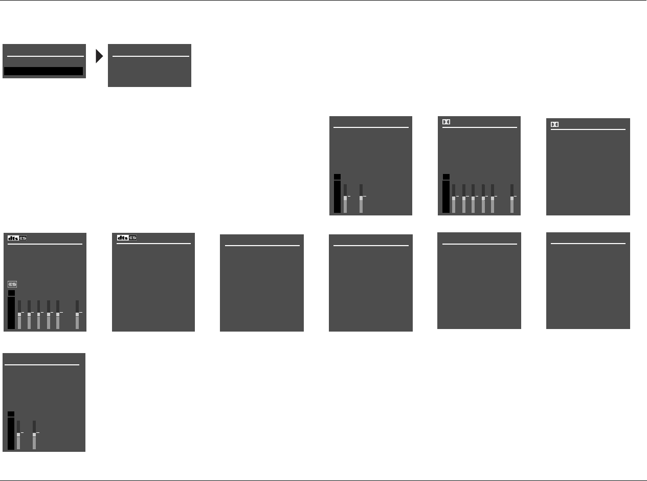
RV-5 Appendix
A-19
MAIN MENU: RESTORE DEFAULTS
2CH STATUS
INPUT
MODE
INPUT TYPE
SAMPLE RATE
dB
0
-6
-15
-30
-45
RL
D STATUS
INPUT
MODE
CHANNELS
BIT RATE
dB
0
-6
-15
-30
-45
RL
EX ENCODING
PG1
CSL
SR LFE
STATUS
INPUT
MODE
CHANNELS
BIT RATE
dB
0
-6
-15
-30
-45
RL
ENCODING
PG1
CSL
SR LFE
STATUS
WORD LENGTH
SAMPLE RATE
PG2 5.1a BYPASS STATUS
INPUT
MODE
INPUT TYPE
2CH BYPASS STATUS
INPUT
MODE
INPUT TYPE
DIGITAL STATUS
INPUT
MODE
INPUT TYPE
SAMPLE RATE
D STATUS PG2
SAMPLE RATE
2.0 ENCODING
DIALOG OFFSET
MIX ROOM
CENTER MIX LVL
SURR MIX LVL
FACTORY SETTINGS
EXIT
RESTORE DEFAULTS
FACTORY SETTINGS
HAVE BEEN RESTORED
PRESS ANY KEY
TO RESTART
Refer to the Restoring Factory-Default Settings section that begins on page 7-4 for more information.
5.1a STATUS
INPUT
MODE
INPUT TYPE
Refer to the Status Menus section that begins on page 2-29 for more information.
dB
0
-6
-15
-30
-45
RL
2CH STATUS
INPUT
MODE
INPUT TYPE
SAMPLE RATE
SAMPLE RATE
ANLG
96kHz
STATUS MENUS
Appendix Lexicon
A-20
INSTALLATION WORKSHEET
INPUT SETUP DVD1 DVD2 LD TV SAT VCR CD PVR GAME TAPE TUNER AUX
NAME
DIGITAL IN
ANALOG IN
ANLG IN LVL
VIDEO IN
COMPONENT IN
2-CH
D
MIC
MAIN ADVANCED
INPUT SELECT
2-CH ANLG BYP
S-VIDEO 16:9
S-VIDEO 4:3 OSD
COMPONENT OSD
ZONE2 IN

INSTALLATION WORKSHEET (continued)
SPEAKER SETUP CUSTOM SETUP SPEAKER DISTANCES LEVELS CALIBRATION
FRONT LEFT/RIGHT
CENTER
SIDE LEFT/RIGHT
REAR LEFT/RIGHT
SUBWOOFER
BGC
ASA
UNITS
BASS PEAK LIMITERS
CAL NOISE
SUB LIMITER
LIMIT ADJ
REAR PANEL CONFIG VOLUME CONTROL SETUP LOCK OPTIONS
Circle one. MAIN PWR ON MODES
8 STEREO INPUTS 5 ST. & (1) 5.1 ANLG
2 ST. & (2) 5.1 ANLG
MUTE LEVEL AUDIO CNTRL
ZONE PWR ON SETUP
MAX VOLUME

Appendix Lexicon
A-22
DISPLAY SETUP TRIGGER SETUP
ON-SCREEN DISPLAY Circle all parameters set to ON.
STATUS REMOTE ONLY
DVD1
DVD2
SAT
VCR
TV
CD
CD
TUNER
AUX
ZONE2 INPUTS
FILM
TV
MUSIC
MUSIC SURR
PLIIx MOV
PLIIx MUS
PLII MOVIE
PLII MUSIC
PRO LOGIC
CIN
MUSIC
NIGHTCLUB
CONCERT HALL
CHURCH
CATHEDRAL
PANORAMA
2-CH SURROUND
2-CHANNEL
MONO LOGIC
MONO SURROUND
MONO
5.1 FILM
5.1 TV
5.1 MUSIC
5.1 PLIIx MOV
5.1 PLIIx MUS
DIGITAL EX
5.1 2-CHANNEL
5.1 MONO LOGIC
5.1 MONO SURR
5.1 MONO
FILM
MUSIC
2-CHAN
5.1a BYPASS
2CH BYPASS
POSITION
FORMAT
BACKGROUND
REMOTE STATE
FRONT-PANEL DISPLAY
STATUS
BRIGHTNESS
A/V SYNC DELAY
CUSTOM NAME
EDIT CUSTOM NAME
AUDIO CONTROLS
BASS
TREBLE
TILT EQ
LOUDNESS
BALANCE
FADER
ZONE2 BALANCE
t
y Group offers the following warranty
:
u
ration of this Warranty?
w
ill remain in effect for three (3) years
a
l date of purchase.
ed?
m
ay be enforced by the original pur-
b
sequent owners during the warranty
d the original dated sales receipt o
r
w
arranty coverage is presented at time
r
ed?
o
vers all defects in material and
o
n this product, except as specified
o
wing are not covered:
s
ulting from:
t, misuse, abuse, or neglect.
t
o follow instructions contained in the
de.
o
r attempted repair unauthorized by
Specialty Group.
t
o perform recommended periodic
n
ance.
e
r than product defects, including lack
m
petence, or experience on the part o
f
c
curring during any shipment of this
laims for shipping damages must be
the carrier.
4. Damage to a unit that has been altered, or on
which the serial number has been defaced, modi-
fied, or removed.
What Expenses will Harman Specialty Group
Assume?
Harman Specialty Group will pay all labor and material
expenses for covered items. Payment of shipping
charges is discussed in the next section of the warranty.
How is Service Obtained?
When this product needs service, write, telephone, or
fax Harman Specialty Group to request information
about where the unit should be taken or sent. When
making a written request, please include your name,
complete address, and daytime telephone number;
the product model and serial numbers; and a descrip-
tion of the problem. Do not return the unit to Harman
Specialty Group without prior authorization.
When Shipping a Product for Service . . .
1. Pay any initial shipping charges, which are the
responsibility of the owner. If necessary repairs are
covered by this warranty, Harman Specialty
Group will pay return shipping charges to any
destination in the United States using the carrier
of our choice.
2. Pack the unit securely. Package insurance is
strongly recommended.
3. Include a copy of the original dated sales receipt.
(A copy of the original dated sales receipt must be
presented whenever warranty service is required.)
4. Do not include accessories such as power cords or
user guides unless instructed to do so.
What are the Limitations of Implied
Warranties?
Any implied warranties, including warranties of mer-
chantability and fitness for a particular purpose, are
limited in duration to the length of this warranty.
What Certain Damages are Excluded?
Harman Specialty Group’s liability for a defective
product is limited to repair or replacement of that
product, at our option. Harman Specialty Group shall
not be liable for damages based on inconvenience;
loss of use of the product; loss of time; interrupted
operation; commercial loss; or any other damages,
whether incidental, consequential, or otherwise.
How do State Laws Relate to this Warranty?
Some states do not allow limitations on the duration of
implied warranties and/or the exclusion or limitation
of incidental or consequential damages. As such, the
above limitations may not apply.
This warranty is not enforceable outside of North
America. This warranty provides specific legal rights.
Additional rights may be provided by some states.
PRODUC
T
Please regi
purchase.
T
or register
sales recei
p
Mr. Mrs.
Single Married
First Name Last Name
Company Title
Mailing Address
City
S
Telephone Number
F
Email Address
Product Model Purchase Date
Version Serial Number
Where did you purchase this product?
Age Education
Under 18 High Scho
o
18-24 College
25-34 Graduate
S
35-49 Certificate:
50-64
65+
How did you learn about this product?
C
Friend Store sale
s
Colleague Store displ
a
Teacher Received
a
Which of the following were most impor
t
Sound Quality
Features Brandname
What are your three favorite magazines
?
1. 2.
What are your three favorite websites?
1. 2.
What features would you like to see ad
d
RV-5 12/06
LIMITED WARRANTY
Harman Specialty Group
3 Oak Park
Bedford, MA 01730-1413
USA
Customer Service
Tel 781-280-0300
Fax 781-280-0495 (Sales)
Fax 781-280-0499 (Service)
Tel 781-280-0300
Fax 781-280-0490
www.lexicon.com

A Harman International Company
Part No. 070-18144 | Rev 0 | 12/06
Product Shipments
900 Middlesex Bldg. #6
Billerica, MA 01821-0017