World Excel 16950235000001 RF Wireless Thermostat Transmitter (433.8MHz Tx) User Manual Layout 1
World Excel Company Ltd RF Wireless Thermostat Transmitter (433.8MHz Tx) Layout 1
User Manual
Description
The RF Remote Control Programmable Thermostat has
LCD display; 5-1-1 (Mo-Fr, Sa, Su) programming with 4 time
zones for each program. Programmed temperature range
from 41°F to 95°F, in step of 0.5°F.
Unpacking
1. Remove all packing items applied to thermostat for
shipment.
2. Remove all items from carton.
3. Check all items for shipping damage. If thermostat
is damaged, promptly inform dealer where you
purchased thermostat.
Features
•Voltage supply – 3.0 VDC; AA alkaline batteries (2).
•Temperature measuring – 32° to 99°F (0° to 39.5°C);
Resolution: 1°F (0.5°C)
• LCD display for Day, Time, Real Temperature/Control
Temperature.
•LCD display for HEAT/COOL/ AUTO/OFF control. Fan
ON/AUTO.
•5-1-1 (Mon-Fri, Sa, Su) with 4 time zone programming.
• Temporary Override of a running Program temperature
until next program time meets.
•Permanent Override maintains room temperature
at a specific temperature for long-term period.
•Defrost indicator for room temperature below
41°F (5°C).
• Low battery indicator for battery level at or below 2.6 V.
• Transmit indicator stays on when RF signal is being
transmitted.
• 12/24 selectable.
•Span +2/-1°F (+1/-0.5°C) for HEAT/COOL/AUTO mode.
• Dual Set point control in AUTO mode.
• Up to 512 addresses can be chosen by the user.
•Filter Over-use Alert – FILTER indicator will flash auto-
matically when the fan/blower is operated over a
specific value.
• Usage Alert – USAGE indicator will flash automatically
when the heater/ cooler is operated over a specific value.
Operation
USER INTERFACE
PUSH BUTTONS
DIP SWITCHES
•Long Cycle Delay is approximately 4 ~ 5 minutes and
Short Cycle Delay is approximately 5 ~ 10 seconds.
•Switch 1 – To select °C or °F temperature (On: °F, Off: °C)
•Switch 2 – To select between Electrical Heating System
and Gas Heating System (On: HG, Off: HE)
•Switch 3-11 – To set the Transmitter address
• Switch 12 – No use
DEFAULT SETTING AFTER RESET
1. Real temperature: °F/°C; Real Temperature will be
displayed after ~5 seconds.
2. Control Temperature: Degree : 70°F (21°C) (HEAT);
75°F (24°C) (COOL).
3. Normal Time: 12:00 AM/MO (12 HR display format).
4. Default Control Mode: System Off Mode.
5. Default Fan Mode: Auto Mode.
6. Default Program Mode: Program OFF.
NORMAL TIME MODE (NT)
After reset or battery replacement, the controller enters
the NT mode with real temperature, current time (default:
12:00 AM & MO) displayed at the LCD; “System” set at OFF;
“Fan” set at FAN AUTO.
DAY/TIME SETTING MODE
TIME AND DAY SETTING
1. At Normal Time mode, press [D/T] key to enter Day/Time
setting mode.
2. “HH:MM” starts flashing. Press [▲/▼]to change current
minutes. Hold for 10-minute fast advance changes.
3. Press [D/T] again, current “Day” is flashing. Press [▲/▼]
to change current day. Hold for faster changes.
4. Press RTN to return to Normal Time Mode.
5. Auto-return to Normal Time Mode if no key input for
10 sec.
12-HOUR OR 24-HOUR SYSTEM
Press [D/T] key for 2 seconds in Normal Time mode to
toggle between 12-hour and 24-hour system.
PROGRAM SETTING MODE
See chart below for default program settings.
MODIFYING THE PROGRAM SETTINGS
1. At Normal Time mode, press [PROG] key to enter
Program Setting mode.
2. The first program slot will be displayed. Icons “MO TU
WE TH FR” & “WAKE” will be on, “HH:MM” will flash.
3. Press [▲/▼]to change program minutes. The program
minutes is set in increments of 10 minutes. Hold for
fast advance changes. Press “PROG” to select. Control
Temperature and HEAT icon will flash.
4. Press [▲/▼]to change control temperature for heat.
Hold for faster changes. Press [SYS] to toggle the
Control Temperature for cool (COOL icon will flash).
5. Press [▲/▼]to change control temperature for cool.
Hold for fast advance changes. Press [PROG] to select.
6. The next program slot will be displayed. Icons “MO TU
WE TH FR” and “OUT” will be on, “HH:MM” will flash.
Repeat steps 2, 3, 4 to change the program settings
for other program slot.
7. If necessary, press [ON/OFF] to disable programming of
the current program slot. “--:-- --” will be seen to indicate
current program slot is disabled. Press [ON/OFF] again
to enable programming of the current program slot.
8. Press [RTN] to return to Normal Time Mode at any time.
9. Auto-return to Normal Time Mode if no key input for
10 sec.
ACTIVATING PROGRAM ON MODE
At startup, the default program mode is off; that is, the
thermostat is in Permanent Override mode. Press [ON/OFF]
totoggle between Program On mode and Permanent
Override mode.
MANUAL OVERRIDE MODE
1. When program is On and System is at Heat or Cool, press
[▲]or [▼]to temporarily override program settings.
2. In AUTO mode, press [▲] or [▼]to modify the heat
set point. Press [SYS] to set the cool set point. The
minimum difference between HEAT & COOL Set
point is preset to 5°F (3°C).
3. Manual override mode maintains until next program
time is met.
PERMANENT OVERRIDE MODE
When the room temperature should be maintained at a
certain temperature for a long time, Permanent Override
Mode should be used. Press [ON/OFF] to toggle between
Program On mode and Permanent Override mode.
FILTER AND SYSTEM USAGE
Every time the Fan is activated, the number of running
hours is counted. When the counter value reaches the Filter
Usage check interval, “FILTER” icon will flash to indicate
it is time to check the air filter.
Every time either HEAT or COOL is activated, the number
of running hours is counted. When the counter value
reaches the System Usage value, “Usage” icon will flash
to indicate that the Heating or Cooling system has been
run for a certain number of hours.
The value of Filter Usage check period and System Usage
can be set from 0-3000 hours, in an interval of 100 hours.
(If the value is set to 0 hr, the counter is disabled.) To
modify the Filter Usage check period:
1. Hold [PROG] for 2 seconds in normal time mode.
2. “FILTER” icon is shown and “1500hr” (default) flashes
on the screen.
3. Press [▲]/ [▼]to modify the setting.
4. Press [RTN] to confirm new setting.
5. “Usage” icon is shown and “1500hr” (default) flashes
on the screen.
6. Press [▲]/ [▼]to modify the setting.
7. Press [RTN] to confirm new setting and return to
normal mode.
Hold [FAN] key for 2 seconds, the Filter Usage counter is
shown. Release [FAN] key, it returns to the normal mode.
Hold [SYS] key for 2 seconds, the system Usage counter is
shown. Release [SYS] key, it returns to the normal mode.
LOW BATTERY INDICATOR
For battery voltage level below 2.6 VDC, Low Battery
indicator is ON.
Indicator is refreshed every 10 minutes and refreshed
after reset.
SYSTEM MODE
SELECT SYSTEM MODE
System mode can be set by pressing [SYS] key in normal
time mode. System mode is set in the sequence of:
OFFàHEATàCOOLàAUTOàOFFà…
SELECT FAN MODE
Fan mode can be set by pressing [FAN] key in normal time
mode. Fan mode is set in the sequence of:
FAN AUTOàFAN ONàFAN AUTOà…
HE/HG setting:
TEMPERATURE MEASURING
Take reading at each 10 sec Interval. Accuracy up to
+/-1°F (+/-0.5°C).
Resolution: 1°F (0.5°C); 32°F to 99°F (0°C to 39.5°C).
For Temperature above 99°F (39.5°C), “--” will be displayed.
For Temperature below 32°F (0°C), “--” will be displayed.
TEMPERATURE CONTROL
When the program is on and specific program time is met,
the specified control temperature will be used to determine
the temperature control. One can override the control tem-
perature by pressing [▲]/ [▼]to desired control temperature.
Temperature control range:
Control resolution is 1°F (0.5°C).
1. “System” set at HEAT:
1. SPAN: +2/-1°F (+1/-0.5°C):
•Heater ON: Real Temperature
<= Control Temperature – 1°F (0.5°C)
•Heater OFF: Real Temperature
>= Control Temperature – +2°F (1°C)
2. “System” set at COOL:
1. SPAN: +2/-1°F (+1/-0.5°C):
• Cooler ON: Real Temperature
>= Control Temperature – +2°F (1°C)
•Cooler OFF: Real Temperature
<= Control Temperature – 1°F (0.5°C)
3. “System” set at AUTO:
“AUTO” means the system can be switched to “HEAT”
or “COOL” automatically according to the control
temperature. In the Auto mode, the Cool setting
temperature must be higher than the heat setting
temperature with 5°F/ 3°C or above, but it does not
restrict to the heat mode and cool mode.
1. SPAN: +2/-1°F (+1/-0.5°C):
• Heater ON Automatically: Real Temperature
<= Heat Control Temperature – 1°F (0.5°C)
•Cooler ON Automatically: Real Temperature
>= Cool Control Temperature – +2°F (1°C)
• Heater and Cooler both off when Real Tempera-
ture is inside the offzone (i.e. the minimum
distance between the Heat & Cool Set points).
Windmill indicator starts to turn when Heat/Cool/Auto
condition & delay condition are both satisfied. The windmill
indicator stays on and will not turn unless the delay
condition is fulfilled. The windmill indicator disappears
when system is off.
Delay for Heat On and Cool On is to prevent short cycling
ofsystem.
DEFROST (SYSTEM IS SET AT HEAT/AUTO)
For Real temperature below 41°F (5°C) and sufficient delay
time, HEATER is always ON and COOLER is always OFF,
regardless of the current control temperature set. LCD
DEFROST indicator ON.
UPPER TEMPERATURE LIMIT (SYSTEM IS SET AT
COOL/AUTO)
For Real temperature above 95°F (35°C) and sufficient delay
time, HEATER is always OFF and COOLER is always ON,
regardless of the current control temperature set.
RFCOMMUNICATION
TO SETUP WITH THE RECEIVER
1. Place batteries in the thermostat controller.
2. Ensure the thermostat controller is in the default state
(i.e. SYSTEM is set to OFF, FAN is set to AUTO). This is to
ensure that the receiver can receive the correct address
from the thermostat controller.
3. Power up the RF receiver, push the “ON/OFF” dip switch
toON position.
4. Set the thermostat FAN to ON:
•The receiver accepts the message and stores
the controller identity.
•The SETUP and the FAN LED are ON.
The thermostat is now set to send signals to the receiver.
At any time, if you find that the RF receiver gets
interference from other wireless thermostat controllers,
push the SETUP dip switch of the receiver to OFF posi-
tion. Then change the address code of the thermostat
controller by selecting other settings of the 9 dip switch-
es located at the back of the controller. Then reset it
and repeat steps 2-4 for each new setup.
5. Setup is completed. You can now set FAN key and
SYSTEM key of the thermostat to desired locations.
Up to 512 addresses can be chosen by the user in case of
interfering with other wireless thermostat controllers.
Transmit indicator stays on when RF signal is being
transmitted. RF signal is transmitted per 10 minutes
for update information.
Auto refresh the System & Fan status at the receiver every
10 minutes by RF signal. Toggling relay at receiver side
to “ON” will not happen when sufficient delay time is
not met.
The RF Receiver Module provides 24 VAC control of
HVAC equipment when used with the wireless thermostat
controller. It can be used with 1H/1C single-zone conven-
tional applications.
NOTE: Before resetting the transmitter, ensure the
“ON/OFF “ dip switch is set to “OFF” in the receiver.
After resetting the transmitter,the “ON/OFF” dip switch
in the receiver is set to “ON” and follows the receiver
setup instruction.
FCC STATEMENT
This device complies with Part 15 of the FCC Rules.
Operation is subject to the following two conditions: (1)
This device may not cause harmful interference, and (2)
This device must accept any interference received, including
interference that may cause undesired operation.
Changes or modifications to this unit
not expressly approved by the party
responsible for compliance could void the user's authority
to operate the equipment.
NOTE: This equipment has been tested and found to
comply with the limits for a Class B digital device, pursuant
to Part 15 of the FCC Rules. These limits are designed to
provide reasonable protection against harmful interference
in a residential installation. This equipment generates, uses
and can radiate radio frequency energy and, if not installed
and used in accordance with the instructions, may cause
harmful interference to radio communications.
However, there is no guarantee that interference will
not occur in a particular installation. If this equipment does
cause harmful interference to radio or television reception,
which can be determined by turning the equipment off and
on, the user is encouraged to try to correct the interference
by one or more of the following measures:
• Reorient or relocate the receiving antenna.
• Increase the separation between the equipment
and receiver.
• Connect the equipment into an outlet on a circuit
different from that to which the receiver is connected.
• Consult the dealer or an experienced radio/TV technician
for help.
Operating Instructions 1UHG7
Form 5S5720 Printed in China
09663
0507/097/VCPVP
WEX001
05/07
1UHG7
LIMITED WARRANTY
DAYTON ONE-YEAR LIMITED WARRANTY.DAYTON®LCD
PROGRAMMABLE WIRELESS THERMOSTAT, MODELS COVERED IN
THIS MANUAL, ARE WARRANTED BY DAYTON ELECTRIC MFG. CO.
(DAYTON) TO THE ORIGINAL USER AGAINST DEFECTS IN WORKMAN-
SHIP OR MATERIALS UNDER NORMAL USE FOR ONE YEAR AFTER
DATE OF PURCHASE. ANY PART WHICH IS DETERMINED TO BE
DEFECTIVE IN MATERIAL OR WORKMANSHIP AND RETURNED TO AN
AUTHORIZED SERVICE LOCATION, AS DAYTON DESIGNATES, SHIPPING
COSTS PREPAID, WILL BE, AS THE EXCLUSIVE REMEDY, REPAIRED OR
REPLACED ATDAYTON’S OPTION. FOR LIMITED WARRANTY CLAIM
PROCEDURES, SEE “PROMPT DISPOSITION” BELOW. THIS LIMITED
WARRANTY GIVES PURCHASERS SPECIFIC LEGAL RIGHTS WHICH
VARY FROM JURISDICTION TO JURISDICTION.
LIMITATION OF LIABILITY.TO THE EXTENT ALLOWABLE UNDER
APPLICABLE LAW, DAYTON’S LIABILITY FOR CONSEQUENTIAL AND
INCIDENTAL DAMAGES IS EXPRESSLYDISCLAIMED. DAYTON’S
LIABILITY IN ALL EVENTS IS LIMITED TO AND SHALL NOT EXCEED
THE PURCHASE PRICE PAID.
WARRANTY DISCLAIMER. ADILIGENT EFFORTHAS BEEN MADE TO
PROVIDE PRODUCT INFORMATION AND ILLUSTRATE THE PRODUCTS
IN THIS LITERATURE ACCURATELY; HOWEVER, SUCH INFORMATION
AND ILLUSTRATIONS ARE FOR THE SOLE PURPOSE OF IDENTIFICATION,
AND DO NOT EXPRESS OR IMPLY A WARRANTY THATTHE PRODUCTS
ARE MERCHANTABLE, OR FIT FOR A PARTICULAR PURPOSE, OR THAT
THE PRODUCTS WILL NECESSARILYCONFORM TO THE ILLUSTRATIONS
OR DESCRIPTIONS. EXCEPT AS PROVIDED BELOW,NO WARRANTY
OR AFFIR-MATION OF FACT, EXPRESSED OR IMPLIED, OTHER THAN
AS STATED IN THE “LIMITED WARRANTY” ABOVE IS MADE OR
AUTHORIZED BY DAYTON.
Technical Advice and Recommendations, Disclaimer.
Notwithstanding any past practice or dealings or trade custom, sales
shall not include the furnishing of technical advice or assistance or
system design. Dayton assumes no obligations or liability on account
of any unauthorized recommendations, opinions or advice as to the
choice, installation or use of products.
Product Suitability. Many jurisdictions have codes and regulations
governing sales, construction, installation, and/or use of products
for certain purposes, which may vary from those in neighboring areas.
While attempts are made to assure that Dayton products comply
with such codes, Dayton cannot guarantee compliance, and cannot
be responsible for how the product is installed or used. Before
purchase and use of a product, review the product applications, and
all applicable national and local codes and regulations, and be sure
that the product, installation, and use will comply with them.
Certain aspects of disclaimers are not applicable to consumer prod-
ucts; e.g., (a) some jurisdictions do not allow the exclusion or limita-
tion of incidental or consequential damages, so the above limitation
or exclusion may not apply to you; (b) also, some jurisdictions do not
allow a limitation on how long an implied warranty lasts, consequent-
ly the above limitation may not apply to you; and (c) by law,during
the period of this Limited Warranty, any implied warranties of implied
merchantability or fitness for a particular purpose applicable to
consumer products purchased by consumers, may not be excluded
or otherwise disclaimed.
Prompt Disposition. Agood faith effort will be made for prompt
correction or other adjustment with respect to any product which
proves to be defective within limited warranty. For any product
believed to be defective within limited warranty,first write or call
dealer from whom the product was purchased. Dealer will give
additional directions. If unable to resolve satisfactorily, write to
Dayton at address below,giving dealer’sname, address, date, and
number of dealer’s invoice, and describing the nature of the defect.
Title and risk of loss pass to buyer on delivery to common carrier.
If product was damaged in transit to you, file claim with carrier.
Manufactured for Dayton Electric Mfg. Co., 5959 W.HowardSt.,
Niles, Illinois 60714-4014 U.S.A.
Hotline: 888-361-8649
MO-FR SA SU
(HEAT/COOL) (HEAT/COOL) (HEAT/COOL)
06:00 am 08:00 am 08:00 am
70°F/75°F 70°F/75°F 70°F/75°F
(21°C/24°C) (21°C/24°C) (21°C/24°C)
08:00 am 10:00 am 10:00 am
62°F/83°F 62°F/83°F 62°F/83°F
(17°C/28°C) (17°C/28°C) (17°C/28°C)
06:00 pm 06:00 pm 06:00 pm
70°F/75°F 70°F/75°F 70°F/75°F
(21°C/24°C) (21°C/24°C) (21°C/24°C)
10:00 pm 11:00 pm 11:00 pm
62°F/78°F 62°F/78°F 62°F/78°F
(17°C/26°C) (17°C/26°C) (17°C/26°C)
WAKE
OUT
BACK
NIGHT
System Mode
HEAT Heating will be activated when the room
mode temperature is lower than the setting
temperature.
COOL Cooling will be activated when the room
mode temperature is higher than the setting
temperature.
AUTO Heating or Cooling will be activated
mode according to the Heat and Cool set point.
Heat set point and Cool set point must
beseparated by a 5°F/3°C dead band.
OFF No Heating and Cooling will be
mode activated at any temperature.
Fan Mode
Fan Fan turns On whenever Heating or Cooling
auto is On. (Depends on HE/HG setting)
Fan Fan stays On all the time.
on
HGHE
Operated at HEAT FAN ON FAN OFF
Operated at COOL FAN ON FAN ON
System Mode Fahrenheit Celsius
HEATMODE
Heat Control Set point 41° to 95° 5° to 35°
COOL MODE
Cool Control Set point 41° to 95° 5° to 35°
AUTO MODE
Heat Control Set point 41° to 90° 5° to 32°
Cool Control Set point 46° to 95° 8° to 35°
Setting of delay dip No Delay Delay
s/w at Controller
“System” operated at HEAT 5-10 sec. 4-5 min.
“System” operated at COOL 4-5 min. 4-5 min.
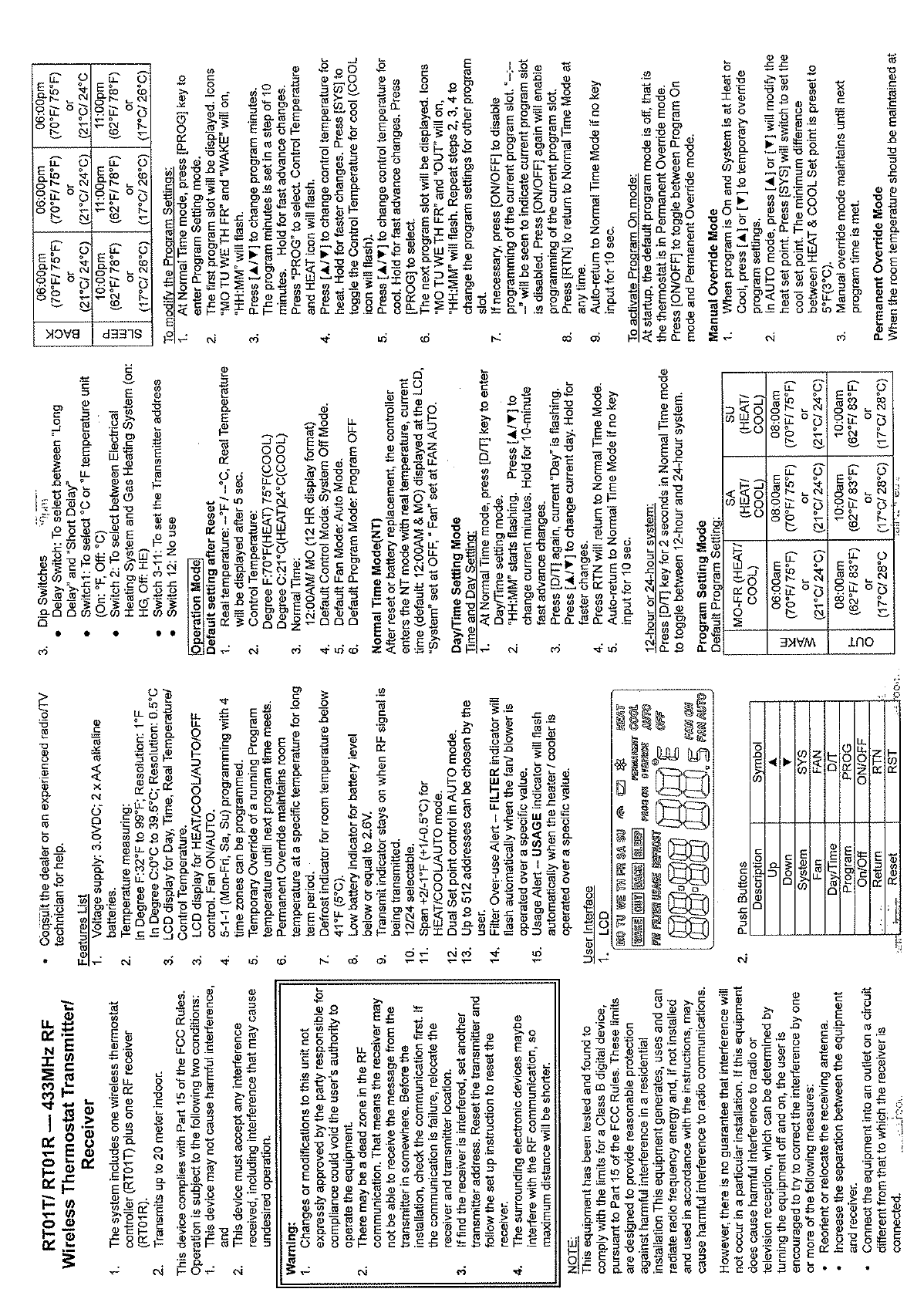
Figure 1 – LCD
Description Symbol
Up ▲
Down ▼
System SYS
Fan FAN
Day/Time D/T
Program PROG
On/Off ON/OFF
Return RTN
Reset RST
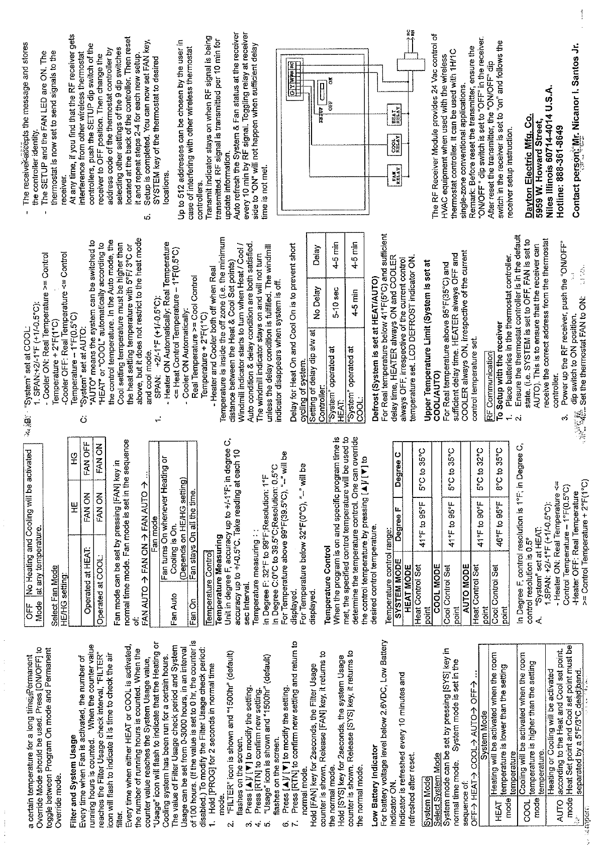
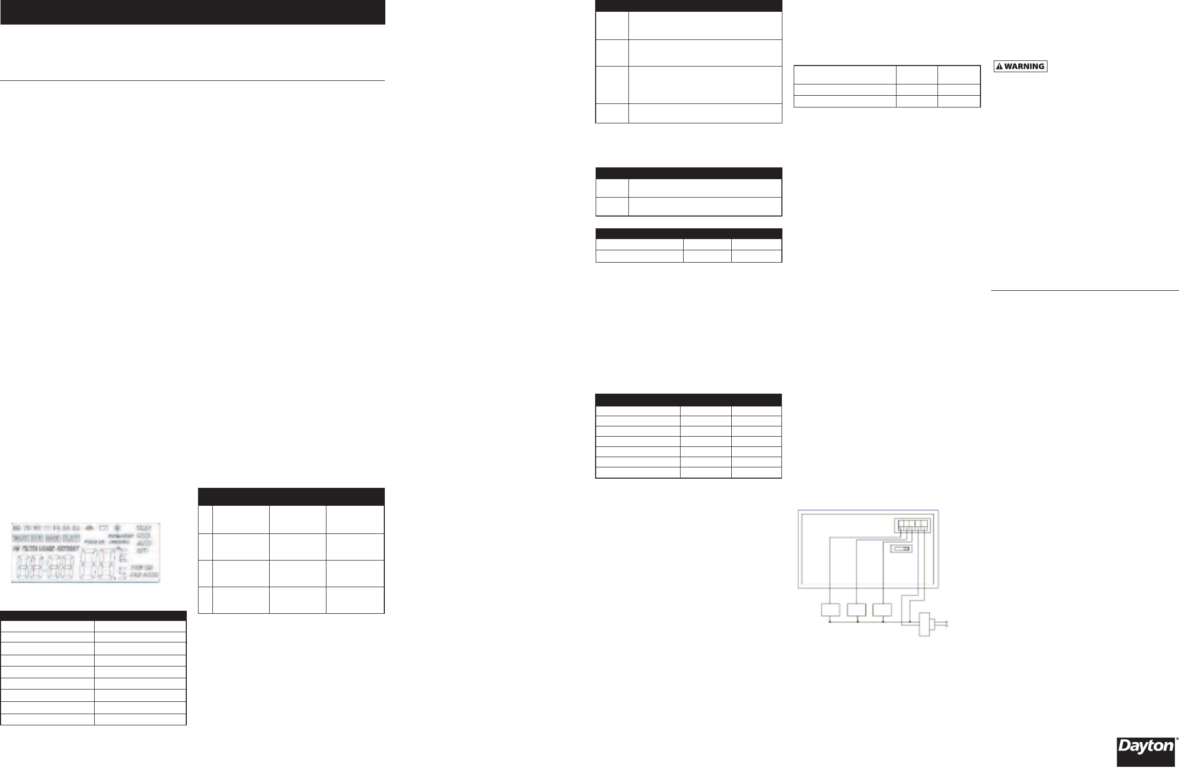
Figure 2
Fan
Relay
Cool
Relay
Heat
Relay
SETUP
OFF ON
RC
G
RH
YRC
RH
W
Please read and save these instructions. Read carefully before attempting to assemble, install, operate or maintain the product
described. Protect yourself and others by observing all safety information. Failure to comply with instructions could result
inpersonal injury and/or property damage! Retain instructions for future reference.
Dayton®LCD Programmable Wireless Thermostat
Descripción
El Termostato Programable con Control Remoto RF incluye una
pantalla LCD; programación 5-1-1 (L-V, S, D) con 4 husos horarios
para cada programa. Gama de temperatura programada de
5°C a 35°C (41 a 95°F), en lugar de 0.3°C (0.5°F).
Desempaque
1. Retire todos los materiales de embalaje aplicados al
termostato para su envío.
2. Retire todos los artículos de la caja de envío.
3. Inspeccione los artículos para comprobar que no se hayan
dañado durante el envío. Si el termostato está dañado,
infórmele prontamente al concesionario de quien compró
el termostato sobre dicho daño.
Características
• Suministro de voltaje – 3.0 VCC; baterías alcalinas tipo AA (2).
• Medición de temperatura – 0° a 39.5°C (32° a 99°F);
Resolución: 0.5°C (1°F)
• Pantalla LCD para Día, Hora, Temperatura Real/Temperatura
Control.
• Pantalla de LCD para control HEAT/COOL/ AUTO/OFF
(CALOR/FRIO/AUTO/APAGADO). Ventilador ON/AUTO
(ENCENDIDO/AUTO).
• 5-1-1 (L-V, S, D) con 4 programaciones de husos horarios.
• Anulación Temporal de una temperatura de Programa en
ejecución hasta que se alcance la próxima hora de programa.
• La Anulación Permanente mantiene la temperatura ambiente
auna temperatura específica por un largo periodo de
tiempo.
• Indicador de deshielo para temperatura ambiente por debajo
de 5°C (41°F).
• Indicador de batería baja para nivel de batería a o por debajo
de 2.6 V.
• El indicador de transmisión permanece encendido cuando
se está transmitiendo la señal RF.
• Seleccionable 12/24.
• Intervalo de +1/-0.5°C (+2/-1°F) para modo HEAT/COOL/AUTO
(CALOR/FRIO/AUTO).
• Control de punto de ajuste doble en el modo AUTO.
•El usuario puede seleccionar hasta 512 direcciones.
• Alerta sobre uso excesivo del filtro – El indicador FILTER
(FILTRO) parpadeará automáticamente si el ventilador/
soplador funciona por encima de un valor específico.
•Alerta sobre el uso – El indicador USAGE (USO) parpadeará
automáticamente si el calentador/enfriador funciona
por encima de un valor específico.
Operación
INTERFASE DEL USUARIO
BOTONES PULSADORES
INTERRUPTORES DIP
• El Retardo de ciclo largo es de aproximadamente 4 a 5
minutos y el Retardo de ciclo corto es de aproximadamente
5a10 segundos.
• Interruptor 1 – Para seleccionar temperatura °C o °F
(Encendido: °F, Apagado: °C)
• Interruptor 2 – Para seleccionar entre Sistema de Calefacción
Eléctrica y Sistema de Calefacción a Gas (Encendido: HG,
Apagado: HE)
• Interruptor 3-11 – Para establecer la dirección del Transmisor
• Transmisor 12 – No tiene uso
AJUSTE PREDETERMINADO LUEGO DEL RESTABLECIMIENTO
1. Temperatura Real: °C/°F; la Temperatura Real se mostrará
luego de 5 segundos.
2. Temperatura Control: Grado : 21°C (70°F) (CALOR); 24°C
(75°F) (FRIO).
3. Duración Normal: 12:00 AM/MO (formato de pantalla
de 12 horas).
4. Modo Control predeterminado: Modo Sistema apagado.
5. Modo Ventilador predeterminado: Modo Auto.
6. Modo Programa predeterminado: Programa APAGADO.
MODO DURACION NORMAL (TN)
Luego de un restablecimiento o reemplazo de batería, el
controlador ingresa al modo TN con temperatura real, hora
actual (predeterminado: 12:00 AM & MO) mostrado en la
pantalla LCD; “Sistema” ajustado en OFF (APAGADO);
“Ventilado” ajustado en FAN AUTO (VENTILADOR AUTO).
MODO AJUSTE DIA/HORA
AJUSTE DE DIA Y HORA
1. En el modo Duración Normal, oprima la tecla [D/T] para
ingresar al modo de ajuste Día/Hora.
2. “HH:MM” comienza a parpadear.Oprima [▲/▼]para cambiar
los minutos actuales. Manténgalo oprimido para hacer
cambios rápidos en incrementos de 10 minutos.
3. Oprima [D/T] nuevamente, “Día” actual parpadeará. Oprima
[▲/▼]para cambiar el día actual. Manténgalo oprimido
para hacer cambios rápidos.
4. Oprima RTN para regresar al modo Duración Normal.
5. Se produce el regreso automático al Modo Duración Normal
si no se oprime ninguna tecla en un espacio de 10 segundos.
SISTEMA DE 12 HORAS O 24 HORAS
Oprima la tecla [D/T] durante 2 segundos en el modo Duración
Normal para alternar entre el sistema de 12 horas y 24 horas.
MODO AJUSTE PROGRAMA
Consulte la tabla para los ajustes de programa
predeterminados.
COMO MODIFICAR LOS AJUSTES DE PROGRAMA
1. En el modo Duración Normal, oprima la tecla [PROG]
para ingresar al modo Ajuste Programa.
2. Se muestra el primer periodo horario del programa. Los
iconos “MO TU WE TH FR” (L M MIE J V) y “WAKE” (DESP.)
estarán iluminados, “HH:MM” parpadeará.
3. Oprima [▲/▼]para cambiar los minutos del programa.
Los minutos del programa se establecen en incrementos
de 10 minutos. Manténgalo oprimido para hacer cambios
rápidos. Oprima “PROG” para seleccionar. Temperatura
Control y el icono HEAT (CALOR) parpadearán.
4. Oprima [▲/▼]para cambiar la temperatura control para
el calor. Manténgalo oprimido para hacer cambios rápidos.
Oprima [SYS] para alternar Temperatura Control para el
frío (el icono COOL [FRIO] parpadeará).
5. Oprima [▲/▼]para cambiar la temperatura control para
el frío. Manténgalo oprimido para hacer cambios rápidos.
Oprima [PROG] para seleccionar.
6. Se muestra el próximo periodo horario del programa. Los
iconos “MO TU WE TH FR” (L M MIE J V) y “OUT” (SALIDA)
estarán iluminados, “HH:MM” parpadeará. Repita los pasos 2,
3y4para cambiar los ajustes del programa para otros perio-
dos horarios del programa.
7. De ser necesario, oprima [ON/OFF] (ENCENDIDO/APAGADO)
para anular la programación del periodo horario del programa
actual. “--:-- --” aparecerá para indicar que se ha anulado
el periodo horario del programa actual. Vuelva a oprimir
[ON/OFF] (ENCENDIDO/APAGADO) para habilitar el
periodo horario del programa actual.
8. Oprima [RTN] para regresar al modo Duración Normal
en cualquier momento.
9. Se produce el regreso automático al Modo Duración Normal
si no se oprime ninguna tecla en un espacio de 10 segundos.
COMO ACTIVAR EL MODO PROGRAMA ENCENDIDO
Durante el arranque, el modo programa predeterminado
está desactivado; o sea, el termostato se encuentra en el modo
Anulación Permanente. Oprima [ON/OFF] (ENCENDIDO/APAGADO)
para alternar entre modo Programa Encendido y modo
Anulación Permanente.
MODO ANULACION MANUAL
1. Cuando el programa se encuentra Encendido y el Sistema
se encuentra ajustado en Calor o Frío, oprima [▲]o[▼]
para anular temporalmente los ajustes de programa.
2. En el modo AUTO, oprima [▲] o [▼]para modificar el punto de
ajuste de calor. Oprima [SYS] para ajustar el punto de ajuste
de frío. La diferencia mínima entre el punto de ajuste de
FRIO y CALOR es preestablecida a 3°C (5°F).
3. El modo de anulación manual continúa hasta que se alcance
la próxima hora de programa.
MODO ANULACION PERMANENTE
Cuando la temperatura ambiente se debe mantener a un nivel
dado por un largo periodo de tiempo, se recomienda utilizar el
Modo Anulación Permanente. Oprima [ON/OFF] (ENCENDIDO/
APAGADO) para alternar entre modo Programa Encendido y
modo Anulación Permanente.
USO DEL FILTRO Y SISTEMA
Cada vez que se active el Ventilador, se cuenta el número de
horas de funcionamiento. Cuando el valor del contador alcanza
el intervalo de revisión de Uso de Filtro, el icono “FILTER” (FILTRO)
parpadeará para indicar que es tiempo de revisar el filtro de aire.
Cada vez que se active CALOR o FRIO, se cuenta el número de
horas de funcionamiento. Cuando el valor del contador alcanza
el valor de Uso del Sistema, el icono “Usage” (Uso) parpadeará
para indicar que el sistema de Calentamiento o de Enfriamiento
ha estado funcionando por un número dado de horas.
El valor del periodo de revisión del Uso del Filtro y del
Uso del Sistema puede establecerse de 0 a 3000 horas
en intervalos de 100 horas. (Si el valor se establece en 0,
se inhabilita el contador.) Para modificar el periodo de
revisión del Uso del Filtro:
1. Oprima [PROG] durante 2 segundos en el modo Duración
Normal.
2. Aparace el icono “FILTER” (FILTRO) y “1500hr” (valor
predeterminado) parpadea en la pantalla.
3. Oprima [▲/▼]para modificar el ajuste.
4. Oprima [RTN] para confirmar el nuevo ajuste.
5. Aparace el icono “Usage” (Uso) y “1500hr” (valor
predeterminado) parpadea en la pantalla.
6. Oprima [▲/▼]para modificar el ajuste.
7. Oprima [RTN] para confirmar el nuevo ajuste y regresar al
modo normal.
Oprima la tecla [FAN] (VENTILADOR) durante 2 segundos,
aparece el contador de Uso del Filtro. Suelte la tecla [FAN]
(VENTILADOR), regresa al modo normal.
Oprima la tecla [SYS] durante 2 segundos, aparece el contador
de Uso del Sistema. Suelte la tecla [SYS], regresa al modo normal.
INDICADOR DE BATERIA BAJA
Cuando el nivel del voltaje de la batería se encuentra por
debajo de 2.6 VCC, se ENCIENDE el indicador de Batería Baja.
El indicador se actualiza cada 10 minutos y luego de un
restablecimiento.
MODO SISTEMA
SELECCIONE MODO SISTEMA
El modo Sistema puede ajustarse oprimiendo la tecla [SYS]
en el modo Duración Normal. El modo Sistema se ajusta
en esta secuencia:
APAGADOàCALORàFRIOàAUTOàAPAGADOà…
SELECCIONE MODO VENTILADOR
El modo Ventilador puede ajustarse oprimiendo la tecla [FAN]
en el modo Duración Normal. El modo Ventilador se ajusta en
esta secuencia:
VENTILADOR AUTOàVENTILADOR ENCENDIDOà
VENTILADOR AUTOà…
Ajuste HE/HG:
MEDICION DE TEMPERATURA
Tome la lectura a cada intervalo de 10 segundos. Precisión hasta
+/-0.5°C (+/-1°F).
Resolución: 0.5°C (1°F); 0°C a 39.5°C (32°F a 99°F).
Para temperaturas por encima de 39.5°C (99°F), aparecerá “--”.
Para temperaturas por debajo de 0°C (32°F), aparecerá “--”.
CONTROL DE TEMPERATURA
Cuando el programa se encuentra encendido y se alcanza una
hora de programa específica, se utilizará la temperatura control
específica para determinar el control de temperatura. Puede
anular la temperatura control oprimiendo [▲/▼]hasta alcanzar
la temperatura de control deseada.
Gama de control de temperatura:
La resolución de control es 0.5°C (1°F).
1. “Sistema” ajustado en CALOR:
1. INTERVALO: +1/-0.5°C (+2/-1°F):
•Calentador ENCENDIDO: Temperatura Real
<= Temperatura Control – 0.5°C (1°F)
•Calentador APAGADO: Temperatura Real
>= Temperatura Control – 1°C (+2°F)
2. “Sistema” ajustado en FRIO:
1. INTERVALO: +1/-0.5°C (+2/-1°F):
•Enfriador ENCENDIDO: Temperatura Real
>= Temperatura Control – 1°C (+2°F)
•Enfriador APAGADO: Temperatura Real
<= Temperatura Control – 0.5°C (+1°F)
3. “Sistema” ajustado en AUTO:
“AUTO” significa que el sistema puede alternarse automáti-
camente entre “CALOR” y “FRIO” según la temperatura
control. En el modo Auto, la temperatura de ajuste de Frío
debe ser más alta que la temperatura de ajuste de Calor,
con una diferencia de 3°C/5°F o más, pero éste límite no
aplica al modo Calor y el modo Frío.
1. INTERVALO: +1/-0.5°C (+2/-1°F):
• Calentador ENCENDIDO Automáticamente:
Temperatura Real
<= Temperatura de Control de Calor – 0.5°C (+1°F)
• Enfriador ENCENDIDO Automáticamente:
Temperatura Real
>= Temperatura de Control de Frío – 1°C (+2°F)
• Calentador y Enfriador apagados cuando la Temperatura
Real se encuentra dentro de la zona de apagado (por
ejemplo, la distancia mínimia entre los puntos de Ajuste
de Calor y de Frío).
El indicador del rotor comienza a girar cuando se satisfacen
tanto la condición Calor/Frío/Auto, como la condición de
retardo. El indicador del rotor permanece encendido y no
girará hasta que finalice la condición de retardo. El indicador
del rotor desaparece cuando el sistema se encuentra apagado.
El retardo para Calor Encendido y Frío Encendido tiene
el propósito de prevenir ciclos cortos en el sistema.
DESHIELO (EL SISTEMA ESTA ESTABLECIDO EN
CALOR/AUTO)
Cuando la Temperatura Real está por debajo de 5°C (41°F)
yhay suficiente tiempo de retardo, el CALENTADOR está
siempre ENCENDIDO y el ENFRIADOR está siempre APAGADO,
independientemente del ajuste de temperatura control actual.
Indicador LCD DEFROST ENCENDIDO.
DESHIELO (EL SISTEMA ESTA ESTABLECIDO EN
CALOR/AUTO)
Cuando la Temperatura Real está por encima de 35°C (95°F)
yhay suficiente tiempo de retardo, el CALENTADOR está
siempre APAGADO y el ENFRIADOR está siempre ENCENDIDO,
independientemente del ajuste de temperatura control actual.
COMUNICACION RF
PARA CONFIGURAR CON EL RECEPTOR
1. Instale las baterías en el controlador para termostatos.
2. Asegúrese que el controlador para termostato se encuentre
en estado predeterminado (por ejemplo, SISTEMA esté
ajustado en APAGADO, VENTILADOR esté ajustado en AUTO).
Esto es para garantizar que el receptor reciba la dirección
correcta del controlador para termostatos.
3. Aplique potencia al receptor RF, lleve el interruptor dip
“ON/OFF” (ENCENDIDO/APAGADO) a la posición ON
(ENCENDIDO).
4. Ajuste el VENTILADOR del termostato en ON (ENCENDIDO):
•El receptor acepta el mensaje y guarda la identidad
del controlador.
•Los LED SETUP (AJUSTE) y FAN (VENTILADOR) se encuen-
tran ENCENDIDOS. El termostato se encuentra ahora
ajustado para enviarle señales al receptor.
En cualquier momento, si nota que el receptor RF recibe
interferencia de otros controladores inalámbricos para
termostatos, oprima el interruptor dip SETUP (AJUSTE)
del receptor a la posición OFF (APAGADO). Luego cambie
el código de direcciones del controlador para termostatos
seleccionando otros ajustes de los 9 interruptores dip ubica-
dos en la parte posterior del controlador.Luego restablézcalo
yrepita los pasos 2 al 4 para cada nuevo ajuste.
5. El ajuste ha finalizado. Ahora puede ajustar la tecla FAN
(VENTILADOR) y la tecla SYSTEM (SISTEMA) del termostato
alas ubicaciones deseadas.
El usuario puede seleccionar hasta 512 direcciones en caso
de interferencia con otros controladores inalámbricos
para termostatos.
El indicador de transmisión permanece encendido cuando
se está transmitiendo la señal RF
.La señal RF se transmite
durante 10 minutos para obtener la información actualizada.
Actualice automáticamente el estado del Sistema y Ventilador
en el receptor cada 10 minutos a través de la señal RF. No se
podrá alternar el relé en el lado del receptor a la posición
“ON” (ENCENDIDO) si no hay suficiente tiempo de retardo.
El Módulo de Receptor RF brinda control de 24 VCA para equipo
HVAC cuando se utiliza con un controlador inalámbrico para
termostatos. Puede utilizarse con aplicaciones convencionales
de zona única 1H/1C.
AVISO: Antes de restablecer el transmisor,asegúrese que el
interruptor dip “ON/OFF” (ENCENDIDO/APAGADO) esté ajustado
en “OFF” (APAGADO) en el receptor. Luego de restablecer el
transmisor,el interruptor dip “ON/OFF” (ENCENDIDO/APAGADO)
en el receptor está ajustado en “ON” (ENCENDIDO) y siga las
instrucciones de configuración del receptor.
DECLARACION DE LA FCC
Este dispositivo cumple con la Sección 15 de las Normas de la
FCC. Su funcionamiento está sujeto a las siguientes dos condi-
ciones: (1) Este dispositivo no debe causar interferencia y (2)
Este dispositivo debe aceptar toda interferencia recibida, incluida
aquélla que puede causar un funcionamiento no deseado.
Los cambios o modificaciones a esta
unidad no aprobados expresamente por
laparte responsable para el cumplimiento podrían anular la
autoridad del usuario conferida para utilizar este equipo.
AVISO: Este equipo ha sido probado, y se consideró que cumple
con los límites de los aparatos digitales de Clase B, de acuerdo
con las especificaciones de la Parte 15 de las Reglas de la FCC.
El objetivo de estos límites es ofrecer protección razonable
contra interferencias perjudiciales en una instalación residencial.
Este equipo genera, utiliza y puede radiar energía de radio-
frecuencia y, si no se instala y utiliza de acuerdo con estas
instrucciones, puede generar interferencia perjudicial para
las radiocomunicaciones.
Sin embargo, no se garantiza que no se producirá interferencia
en una instalación en particular. Si su equipo causa interferencia
perjudicial para la recepción de radio o televisión, que puede
averiguar apagando y encendiendo el equipo, intente corregirla
mediante uno o varios de los siguientes procedimientos:
• Vuelva a orientar o cambie de lugar la antena receptora.
• Aumente la separación entre el equipo y el receptor.
• Conecte el equipo a un tomacorriente en un circuito
diferente al que esté conectado el receptor.
• Consulte al distribuidor o a un técnico experimentado
de radio y televisión para solicitar asistencia.
Manual de Instrucciones de Operación 1UHG7
Formulario 5S5720 Impreso en China
09663
0507/097/VCPVP
WEX001
05/07
1UHG7
GARANTIA LIMITADA
GARANTIA LIMITADA DE DAYTON POR UN AÑO. DAYTON ELECTRIC
MFG. CO. (DAYTON) LE GARANTIZA AL USUARIO ORIGINAL QUE LOS
MODELOS TRATADOS EN ESTE MANUAL DEL TERMOSTATO INALÁMBRICO
PROGRAMABLE CON PANTALLA LCD DAYTON®ESTAN LIBRES DE DEFECTOS
EN LA MANO DE OBRA O EL MATERIAL, CUANDO SE LES SOMETE A USO
NORMAL, POR UN AÑO A PARTIR DE LA FECHA DE COMPRA. CUALQUIER
PARTE QUE SE HALLE DEFECTUOSA, YA SEA EN EL MATERIAL O EN LA MANO
DE OBRA, Y SEA DEVUELTA (CON LOS COSTOS DE ENVIO PAGADOS POR
ADELANTADO) A UN CENTRO DE SERVICIO AUTORIZADO DESIGNADO POR
DAYTON, SERA REPARADA O REEMPLAZADA (NO EXISTE OTRA POSIBILIDAD)
SEGUN LO DETERMINE DAYTON. PARA OBTENER INFORMACION SOBRE LOS
PROCEDIMIENTOS DE RECLAMO CUBIERTOS EN LA GARANTIA LIMITADA,
VEA LA SECCION “ATENCION OPORTUNA” QUE APARECE MAS ADELANTE.
ESTA GARANTIA LIMITADA CONFIERE AL COMPRADOR DERECHOS LEGALES
ESPECIFICOS QUE VARIAN DE JURISDICCION A JURISDICCION.
LIMITES DE RESPONSABILIDAD. EN LA MEDIDA EN QUE LAS LEYES
APLICABLES LO PERMITAN, LA RESPONSABILIDAD DE DAYTON POR LOS
DAÑOS EMERGENTES O INCIDENTALES ESTAEXPRESAMENTE EXCLUIDA.
LA RESPONSABILIDAD DE DAYTON EXPRESAMENTE ESTALIMITADA Y NO
PUEDE EXCEDER EL PRECIO DE COMPRA PAGADO POR EL ARTICULO.
EXCLUSION DE RESPONSABILIDAD DE LA GARANTIA. SE HAN HECHO
ESFUERZOS DILIGENTES PARA PROPORCIONAR DILIGENTEMENTE PARA
PROPORCIONAR INFORMACION E ILUSTRACIONES APROPIADAS SOBRE EL
PRODUCTO EN ESTE MANUAL; SIN EMBARGO, ESTA INFORMACION Y LAS
ILUSTRACIONES TIENEN COMO UNICO PROPOSITO LA IDENTIFICACION DEL
PRODUCTO Y NO EXPRESAN NI IMPLICAN GARANTIA DE QUE LOS PRODUCTOS
SEAN VENDIBLES O ADECUADOS PARA UN PROPOSITO EN PARTICULAR NI
QUE SE AJUSTAN NECESARIAMENTE A LAS ILUSTRACIONES O DESCRIPCIONES.
CON EXCEPCION DE LO QUE SE ESTABLECE A CONTINUACION, DAYTON
NO HACE NI AUTORIZA NINGUNA GARANTIA O AFIRMACION DE HECHO,
EXPRESA O IMPLICITA, QUE NO SEA ESTIPULADA EN LA “GARANTIA
LIMITADA” ANTERIOR.
Consejo Técnico y Recomendaciones, Exclusiones de Responsabilidad.
Apesar de las prácticas, negociaciones o usos comerciales realizados previa-
mente, las ventas no deberán incluir el suministro de consejo técnico o
asistencia o diseño del sistema. Dayton no asume ninguna obligación o
responsabilidad por recomendaciones, opiniones o consejos no autorizados
sobre la elección, instalación o uso de los productos.
Adaptación del Producto. Muchas jurisdicciones tienen códigos o regula-
ciones que rigen la venta, la construcción, la instalación y/o el uso de produc-
tos para ciertos propósitos que pueden variar con respecto a los aplicables a
las zonas vecinas. Si bien se trata de que los productos Dayton cumplan con
dichos códigos, no se puede garantizar su conformidad y no se puede hacer
responsable por la forma en que se instale o use su producto. Antes de
comprar y usar el producto, revise su aplicación y todos los códigos y
regulaciones nacionales y locales aplicables y asegúrese de que el producto,
la instalación y el uso los cumplan.
Ciertos aspectos de limitación de responsabilidad no se aplican a productos
al consumidor; es decir (a) algunas jurisdicciones no permiten la exclusión ni
limitación de daños incidentales o consecuentes, de modo que las limitaciones
oexclusiones anteriores quizás no apliquen en su caso; (b) asimismo, algunas
jurisdicciones no permiten limitar el plazo de una garantía implícita, por
lo tanto, la limitación anterior quizás no aplique en su caso; y (c) por ley,
mientras la Garantía Limitada esté vigente no podrán excluirse ni limitarse
en modo alguno ninguna garantía implícita de comercialización o de
idoneidad para un propósito en particular aplicables a los productos al
consumidor adquiridos por éste.
Atención Oportuna. Se hará un esfuerzo de buena fe para corregir
puntualmente, o hacer otros ajustes, con respecto a cualquier producto
que resulte defectuoso dentro de los términos de esta garantía limitada. En
el caso de que encuentre un producto defectuoso y que esté cubierto dentro
de los límites de esta garantía haga el favor de escribir primero, o llame,
al distribuidor a quien le compró el producto. El distribuidor le dará las
instrucciones adicionales. Si no puede resolver el problema en forma
satisfactoria, escriba a Dayton a la dirección a continuación, dando el
nombre del distribuidor, su dirección, la fecha y el número de la factura
del distribuidor y describa la naturaleza del defecto. La propiedad del artículo
yel riesgo de pérdida pasan al comprador en el momento de la entrega
del artículo a la compañía de transporte. Si el producto se daña durante
el transporte, debe presentar su reclamo a la compañía transportista.
Fabricado para Dayton Electric Mfg. Co., 5959 W. Howard St.,
Niles, Illinois 60714-4014 EE.UU.
Servicio de asistencia técnica: 888-361-8649
L-V SD
(CALOR/FRIO) (CALOR/FRIO) (CALOR/FRIO)
06:00 am 08:00 am 08:00 am
21°C/24°C 21°C/24°C 21°C/24°C
(70°F/75°F) (70°F/75°F) (70°F/75°F)
08:00 am 10:00 am 10:00 am
17°C/28°C 17°C/28°C 17°C/28°C
(62°F/83°F) (62°F/83°F) (62°F/83°F)
06:00 pm 06:00 pm 06:00 pm
21°C/24°C 21°C/24°C 21°C/24°C
(70°F/75°F) (70°F/75°F) (70°F/75°F)
10:00 pm 11:00 pm 11:00 pm
17°C/26°C 17°C/26°C 17°C/26°C
(62°F/78°F) (62°F/78°F) (62°F/78°F)
DESP.
SALIDA
REGRESO
NOCHE
Modo Sistema
Modo El sistema de calentamiento se activará si
CALOR la temperatura ambiente es más baja que
la temperatura de ajuste.
Modo El sistema de enfriamiento se activará si
FRIO la temperatura ambiente es más baja que
la temperatura de ajuste.
Modo El sistema de Calentamiento o Enfriamiento se
AUTO activará según el punto de ajuste de Calor y Frío.
Elpunto de ajuste de Calor y el punto deajuste
deFrío deberán estar separados por una banda
muerta de 3°C/5°F.
Modo Los sistemas de Calentamiento y Enfriamiento
APAGADO no se activarán a ninguna temperatura.
Modo Ventilador
Ventilador El Ventilador se Encienda cuando el sistema
auto de Calentamiento o Enfriamiento se encuentra
Encendido. (Según el ajuste HE/HG)
Ventilador El ventilador se mantiene encendido
encendido todo el tiempo.
HGHE
Funcionando Ventilador Ventilador
en CALOR Encendido Apagado
Funcionando Ventilador Ventilador
en FRIO Encendido Encendido
Modo Sistema Fahrenheit Celsio
MODO CALOR
Control de Calor Punto de ajuste 41° a 95° 5° a 35°
MODO FRIO
Control de Frío Punto de ajuste 41° a 95° 5° a 35°
MODO AUTO
Control de Calor Punto de ajuste 41° a 90° 5° a 32°
Control de Frío Punto de ajuste 46° a 95° 8° a 35°
Ajuste de interruptor de Sin Retardo
retardo s/w en el Controlador Retardo
“Sistema” funcionando en CALOR 5-10 segs. 4-5 min.
“Sistema” funcionando en FRIO 4-5 min. 4-5 min.
Figura 1 – Pantalla LCD
Descripción Símbolo
Arriba ▲
Abajo ▼
Sistema SYS
Ventilador FAN
Día/Hora D/T
Programa PROG
Encendido/Apagado ON/OFF
Regresar RTN
Restablecer RST
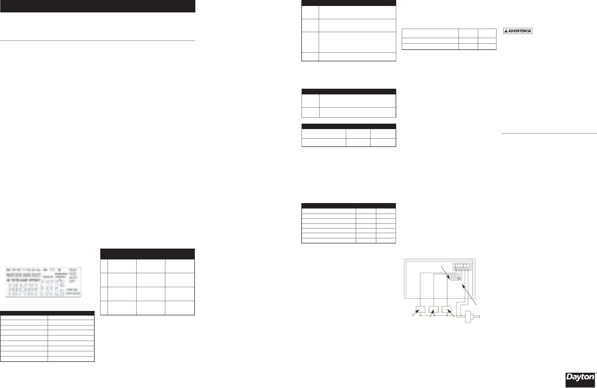
Figura 2
AJUSTE
OFF ON
RC
G
RH
YRC
RH
W
Relé del
Ventilador
Relé de
Frío
Relé de
Calor
OFF (APAGADO)
ON (ENCENDIDO)
Por favor lea y guarde estas instrucciones. Léalas cuidadosamente antes de tratar de montar, instalar, operar o dar mantenimiento
alproducto aquí descrito. Protéjase usted mismo y a los demás observando toda la información de seguridad. ¡El no cumplir con las
instrucciones puede ocasionar daños, tanto personales como a la propiedad! Guarde estas instrucciones para referencia en el futuro.
Termostato Inalámbrico Programable con Pantalla LCD
Dayton®