World Excel ZN020TC15 Wireless Zone thermostat User Manual WT830 ZN020 TC IM 150616
World Excel Company Ltd Wireless Zone thermostat WT830 ZN020 TC IM 150616
User Manual
WT830 and ZN020 Wireless Zone Thermostat
Instruction Manual
Warning: Changes or modifications to this unit not
expressly approved by the party
responsible for compliance could void the user’s
authority to operate the equipment.
NOTE: This equipment has been tested and found to
comply with the limits for a Class
B digital device, pursuant to Part 15 of the FCC Rules.
These limits are designed to
provide reasonable protection against harmful
interference in a residential installation.
This equipment generates, uses and can radiate radio
frequency energy and, if not
installed and used in accordance with the instructions,
may cause harmful interference
to radio communications.
However, there is no guarantee that interference will not
occur in a particular
installation. If this equipment does cause harmful
interference to radio or television
reception, which can be determined by turning the
equipment off and on, the user is
encouraged to try to correct the interference by one or
more of the following measures:
Reorient or relocate the receiving antenna.
Increase the separation between the equipment
and receiver.
Connect the equipment into an outlet on a circuit
different from that to which the receiver is
connected.
Consult the dealer or an experienced radio/TV
technician for help.
Room Sensor unit installation
Installation Location
The room sensor should be mounted on an inner wall ~1.5m
above the floor in a position where it is readily affected by
changes of the general room temperature with freely
circulating air.
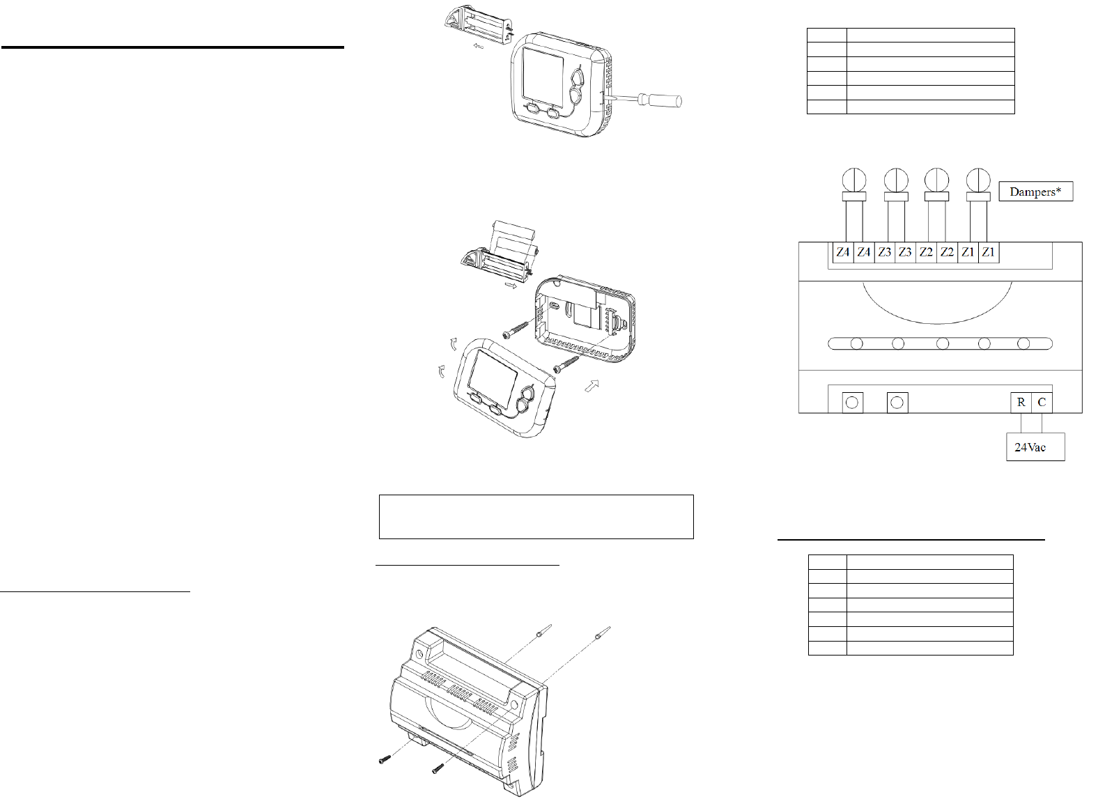
Opening the Cover
Pull out the battery drawer and use a screwdriver to press on the
spot shown below in order to detach the front shell from its base
as shown in the below Figure.
Mounting
Ensure that the surface is level.
Drilling 2 holes at wall and fix the wall anchor.
Fasten the thermostat with 2 pcs of long screws through the 2
mounting holes.
Insert two fresh AAA alkaline batteries into the drawer according to
the polarity marked inside, then slide the drawer back into the place
as shown in the above Figure.
Zone output unit installation
Mounting
ZN020 can be mounted on Din rail or mounted on wall directly
Drilling 2 holes at wall and fix the wall anchor.
Fasten the Zone output unit with 2 pcs screws at top housing.
Wiring connection
Wiring power and device according to the label
R 24Vac input
C 24Vac common input
Z1 Zone 1 dry contact
Z2 Zone 2 dry contact
Z3 Zone 3 dry contact
Z4 Zone 4 dry contact
All damper outputs are dry contact
Add Room sensor to Zone output unit
1. Use dip switch to select system option
Pole Selection
1 RF channel address 1
2 RF channel address 2
3 RF channel address 3
4 RF channel address 4
5 Reserved
6 Reserved
2. Select any combination of RF channel from pole 1
st
to
4
th
3. Power up ZN020 with 24Vac
4. Press and hold <SW1> button to enter add/drop mode
Release button until all LED flashing
5. Power up Room sensor unit, the room sensor should be
not added or finished dropping.
If there are any display or functional errors, please
remove the batteries for about 30 sec to reset the
thermostat.
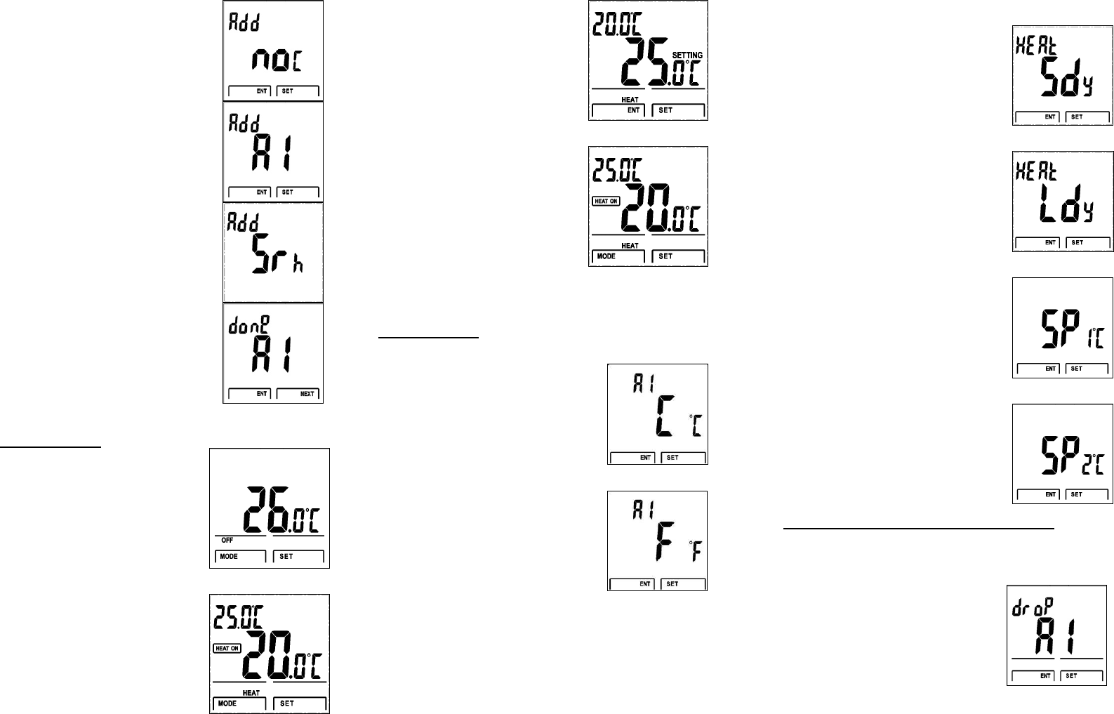
6. Room sensor display “no C”
when it is not connected
7. Press Up /Down to select Zone
area 1 to Zone area 4
Please select Area 1 for the first
adding.
8. Press SET to confirm, room unit
will search the Zone output unit
9. LCD shows “done” and the
zone area, press Next for initial
internal setting.
10. Repeat step 4 to 9 for other Room unit
On/ Off mode
User can press <MODE> key to
select OFF or ON mode
OFF mode:
Zone damper will be off and
Room unit only display room
temperature, set point cannot be
changed in this mode
On mode:
HEAT will be activated, this is
based on the operation mode
setting in Area 1 room unit
Room unit display the set point
value at the top left corner
User can press up/down to
change set point.
When user enter setting mode,
room unit display SETTING icon. The
top left corner value will be room
temperature.
Press <SET> key to confirm the
changes and back to normal page
Press<ENT> key back to normal
page without changing set point
Internal Setting
Hold <SET> Key to enter internal setting
mode
Press <Up/Down> to select C scale of F
scale
Press <SET> to confirm
Press Up/Down to select heater delay
time.
Sdy: 10 seconds
Ldy: 3 minutes
If selected Ldy and heater is off,
damper output cannot be turned on
within 3 minutes.
Press SET to confirm
Press Up/Down to select the span
1
o
C(2
o
F) or 2
o
C(4
o
F)
Press SET to confirm and back to
normal mode
Drop Room sensor from Zone output unit
1. Press and hold SW1 button to enter add/drop mode
Release button until all LED flashing
2. Press<MODE> and <SET> key to
enter drop mode
3. Press <SET> to confirm
Press<ENT> to cancel and exit
drop mode
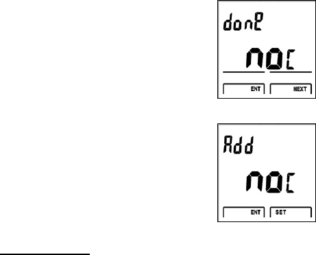
4. Room unit display “done” and
“no c” after finish the dropping
5. Press “Next”, the room unit is
ready for adding
Specification:
Room unit sensor
Input Voltage: 3Vdc, 2* 1.5V AAA alkaline
batteries
Transmit Frequency: 918-924MHz
Operating Temperature: 32 – 122 °F / 0 – 50 °C
Storage Temperature: 23 – 140 °F / -5 – 60 °C
Operating Humidity: 5-95% RH non-condensing
Temperature Accuracy: +/- 1 °F / 0.5 °C
Zone output unit:
Input Voltage: 24Vac +/- 20%
Relay Contact Voltage: 24 Vac +/-20%
Rated Current: 24Vac,1A (each output)
Terminals: 18-24AWG
Transmit Frequency: 918-924MHz
Operating Temperature: 32 – 122 °F / 0 – 50 °C
Storage Temperature: 23 – 140 °F / -5 – 60 °C
Operating Humidity: 5-95% RH non-condensing