Wuerth Elektronik eiSos and Co KG AMB2300 Bluetooth module BlueNiceCom IV User Manual

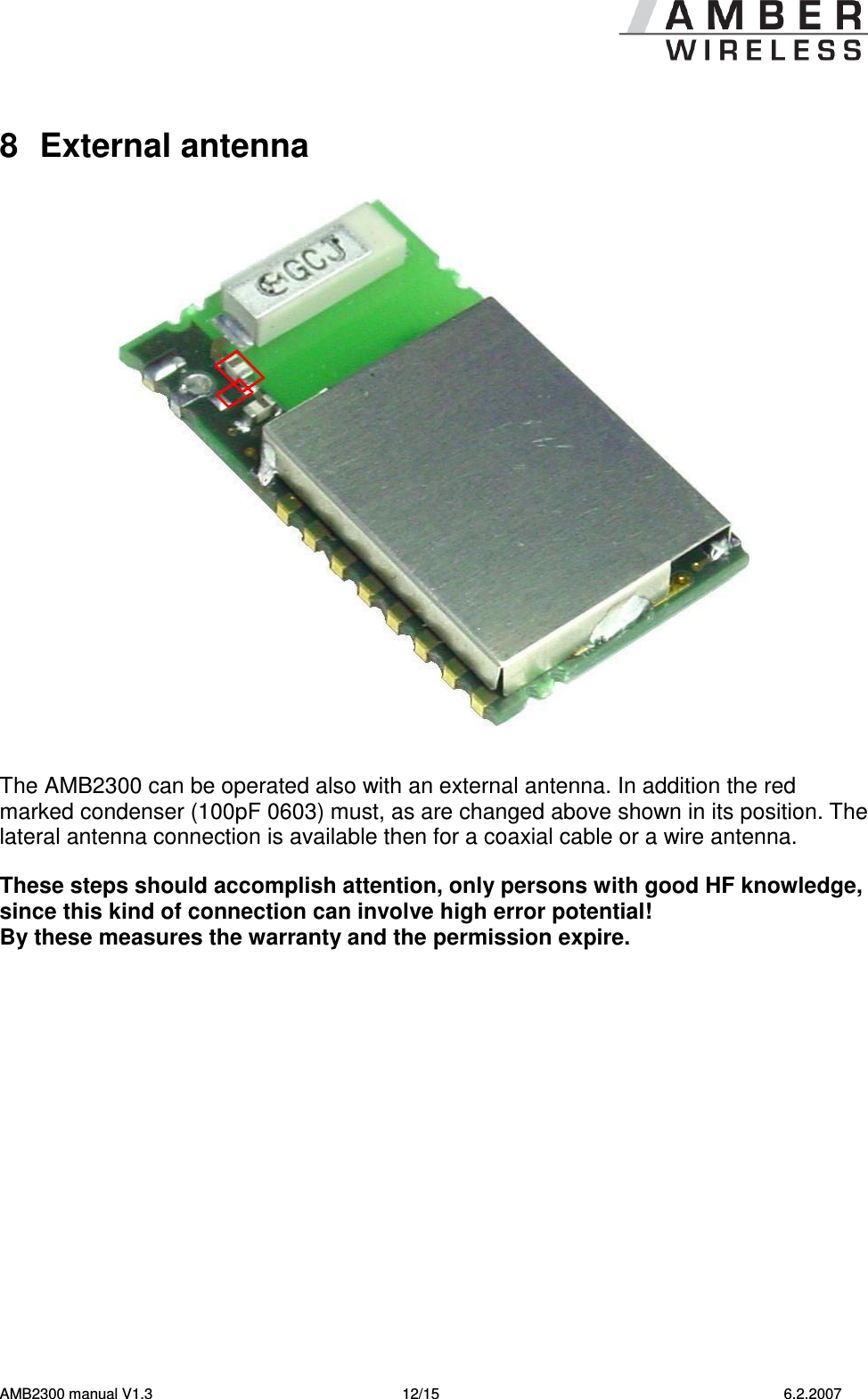
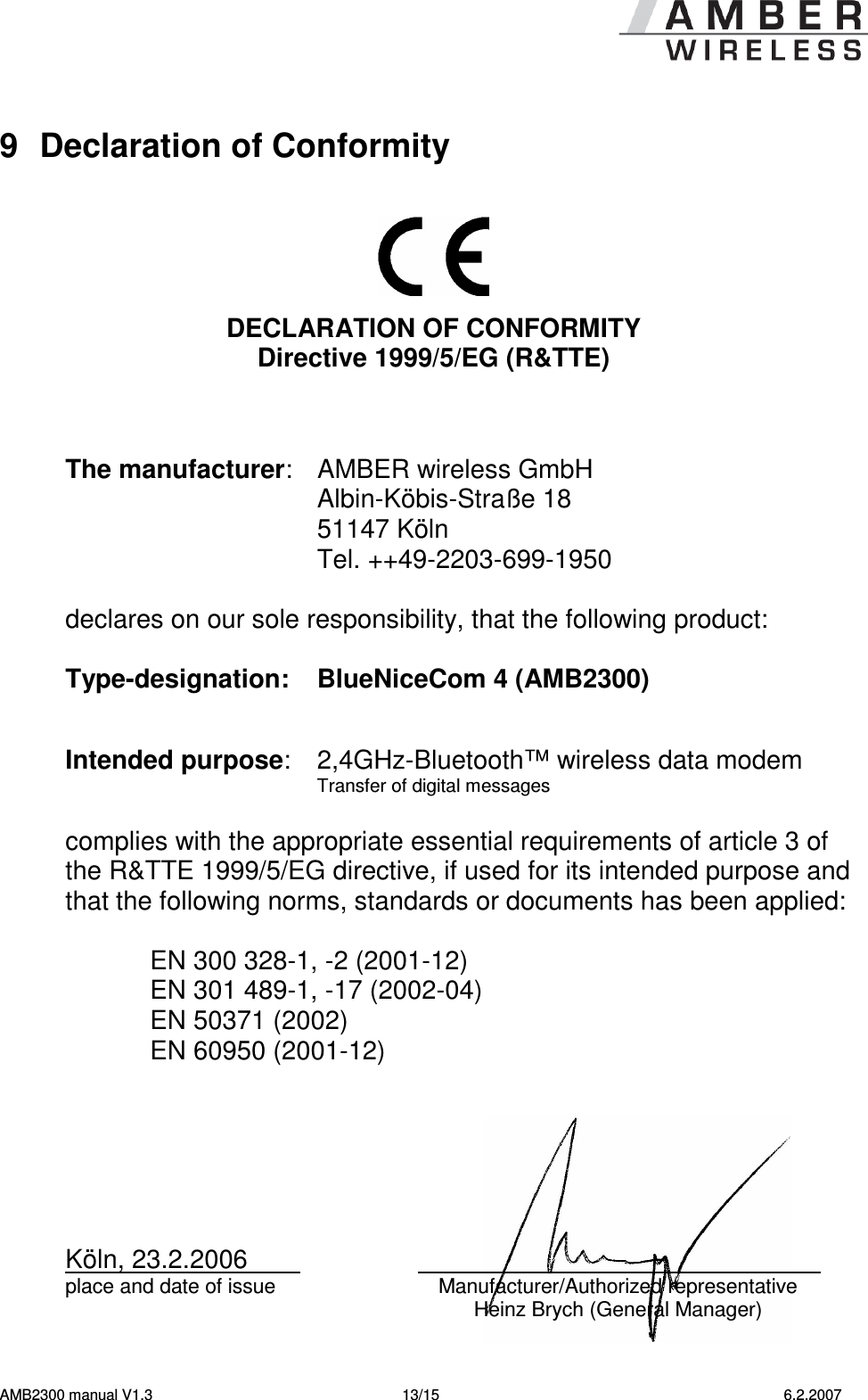
AMBER Wireless GmbH Bluetooth module BlueNiceCom IV

User manual

Annex No.5 Page 1 of 16                 Users Manual
           Manual AMB2300 Version 1.3 BlueNiceCom 4                           Development department  AMBER wireless GmbH Hawstraße 2a D-54290 Trier Tel. +49 (0) 651-99355-0 Fax +49 (0) 651-99355-69
  AMB2300 manual V1.3  2/15  6.2.2007    Table of contents  1 General ................................................................................................................................. 3 2 Technical data...................................................................................................................... 3 2.1 DEFAULT SETTINGS.......................................................................................................... 4 2.2 PIN ASSIGNMENT.............................................................................................................. 4 2.2.1 Pinning.................................................................................................................... 4 2.2.2 Pinning table ........................................................................................................... 5 2.2.3 Serial interface of the BlueNicecom 4...................................................................... 6 2.2.4 Block diagram ......................................................................................................... 7 2.3 DIMENSION....................................................................................................................... 8 3 Details for Layout ................................................................................................................ 9 4 Soldering & Reflow.............................................................................................................. 9 4.1 DESCRIPTION................................................................................................................... 9 4.2 RECOMMENDATION FOR FOOTPRINTS.............................................................................. 10 5 Replace of BNC3 to BNC4................................................................................................. 11 6 Minimum connection to run the BNC4 ............................................................................. 11 7 Further documents ............................................................................................................ 11 8 External antenna................................................................................................................ 12 9 Declaration of Conformity................................................................................................. 13 10 Important notes.................................................................................................................. 14 10.1 COMPLIANCE STATEMENT............................................................................................. 14 10.2 DISCLAIMER................................................................................................................. 15 10.3 TRADEMARKS.............................................................................................................. 15 10.4 LIMITATION OF USE...................................................................................................... 15
  AMB2300 manual V1.3  3/15  6.2.2007  1  General BlueNiceCom 4 Bluetooth-Modul with UART-interface and integrated Chip-antenna  • Bluetooth Class 2 module • Bluetooth Specification 2.0 compatible • Support of Bluetooth Audio • Integrated profiles: SPP, GAP, SDAP   • Supported profiles: DUN, OBEX, HSP etc.               • UART interface • Integrated chip antenna   AMBER wireless provides with the BlueNiceCom 4 a certified, qualified listed Bluetooth-module, based  on  LMX9830  from  National  Semiconductor.  This  compact  and  inexpensive  Bluetooth-module is qualified for a serial data or audio transmission. The module has an integrated chip-antenna and can be placed into a circuit like a SMD-part.  BlueNiceCom IV comes with an integrated firmware with the complete Bluetooth Stack (Bluetooth 2.0).  A Point-to-Point connection and a Point-to-Multipoint (Piconet) connection are supported by the firmware. Up to seven active links (Piconet) and one SCO-link (Audio) is possible.  The module can be integrated easily in a system. According to the application and the settings the BlueNiceCom 4 can work as a stand-alone-slave-module e.g. as a virtual cable replacement in combination with another commercial Bluetooth system. A development environment AMB2300-EV is available.  2  Technical data Voltage supply  2.9 to 3.3V Current consumption  typ. 65mA RF output  typ. 0dBm (Class 2) Rx sensitivity  typ. –80dBm Data rate UART  2,4 to 921,6 kbits/s Operating temperature  -20°C to 70°C Antenna  Integrated chip antenna   Connection of an external antenna is possible Dimension    27,5 x 16 x3,5mm Miscellaneous  All further technical datas according to the LMX9830 module of   National Semiconductor  Order number  AMB2300 Part code:  BlueNiceCom 4 Abb. 1
  AMB2300 manual V1.3  4/15  6.2.2007 2.1  Default settings   All parameter are stored at the internal EEPROM. See datasheet LMX9830  Parameter  EEPROM  Address Default set ups  Notice DeviceName length  0018  18  Device Name + NULL-Terminierung DeviceName  0019 – 0040  <Variabel>  Device Name  Consist of „ BNC4- “  and BD_ADDR    2.2  Pin assignment 2.2.1  Pinning             Antenna Figure. 2
  AMB2300 manual V1.3  5/15  6.2.2007 2.2.2  Pinning table  Pin name  Typ1  Notice GND  I  Ground OP3  I  At start up configuration of the UART-data rate,  otherwise internal use PG7  I/O  GPIO (default setting as output, display a data exchange) SCLK  I/O  Audio PCM Interface Clock SFS  I/O  Audio PCM Interface Frame Synchronization SRD  I  Audio PCM Interface Receive Data Input STD  O  Audio PCM Interface Transmit Data Output OP5  I  Configuration UART-data rate at Start up OP4  I I/O Configuration UART-data rate at Start up,  otherwise GPIO RESETBB#  I  Reset, internal Pull up, active low CTS#_BT  I  Host Serial Port Clear To Send, active low 2 - see footnote 2 RTS#_BT  O  Host Serial Port Request To Send, active low 3 - see footnote 3 TX_BT  O  Host Serial Port Transmit Data RX_BT  I  Host Serial Port Receive Data PG6  I/O  GPIO (default setting as output, display a link connection) NC  I  Not connected, no ground  Vcc  I  Power consumption, 2,9V to 3,6V  Antenna  O GND  O Connection for external antenna4 - see footnote 4  The signal level is equivalent to the power consumption (2,9V to 3,6V) of the BlueNiceCom 4 and has to be matched, if the Host system is working with a different signal level.                                                                           1 I = Input, O = Output 2 Connect with ground if not used 3 Not connected if not used 4 In as-delivered condition the antenna connection is internally not connected
  AMB2300 manual V1.3  6/15  6.2.2007 OP3, OP4, OP5:    Configuration of the serial interface. Must be connected.             RX_BT, TX_BT, RTS#_BT, CTS#_BT:   2.2.3  Serial interface of the BlueNicecom 4.  The interface serves for communication with the BlueNiceCom4. The hardware handshake is used (RTS/CTS). If this should not be supported by the host system, RTS#_BT and CTS#_BT must be short circuit and/or CTS#_BT put on Low levels This can lead however to overrun! We recommended therefore urgently to use handshake.   ResetBB#:      Internal Pull up, low active. No external circuit is necessary.   SCLK, SFS, SRD, STD:    Audio interface. If not used, Pins does not attached      PG6 , PG7:      I/O Ports. If not used, Pins does not attached  Vcc, Gnd      Power consumption                        OP3 OP4 OP5  Function 0  1  0  Automatically baud rate-detection 1  0  0  Baud rate-adjustment is read from the EEPROM 1  0  1  9600 bps 1  1  0  115200 bps 1  1  1  921600 bps
  AMB2300 manual V1.3  7/15  6.2.2007   2.2.4  Block diagram
  AMB2300 manual V1.3  8/15  6.2.2007  2.3  Dimension  BlueNiceCom IV has 1mm x 2mm soldering pads with a raster of 2mm to be solder direct on a motherboard
  AMB2300 manual V1.3  9/15  6.2.2007  3  Details for Layout To achieve the maximum of range no metal has to be near or under the antenna. The antenna should have a distance of 8mm to any ground, strip line or component. Most suitable is to place the antenna at the margin of the motherboard. The figure shows the area which should be free of metal (ground, strip line, components, etc..).     The area off 12mm between the soldering pads on the bottom side should (e.g. with adhesive tape) additional isolated, if any strip line is under the module to avoid any short circuit.     4  Soldering & Reflow 4.1  Description  •  Reflow appropriate  •  The temperature curve depends on the motherboard it´s character, like the number and conditioning of parts, etc. Please ask your manufactor.  •  Depending on the limit values of the components following limits are not allowed to excess  260°C max. 40s (LMX) 250°C max. 20s (Chip-antenna) 200°C max. 120s (Chip-antenna)
  AMB2300 manual V1.3  10/15  6.2.2007  4.2  Recommendation for Footprints     All dimensions in mm
  AMB2300 manual V1.3  11/15  6.2.2007 5  Replace of BNC3 to BNC4     CTS, RTS, TX, RX,    no change (UART) Vcc, GND     no change Reset    At BNC4 no external connection necessary ISEL2    PG6 (I/O) no connection necessary ISEL1    N.C. Pin not connected!          ENV1     OP3 (Input) must be connected because of UART configuration  ENV0    PG7 (I/O) no connection necessary LSTAT_0, LSTAT1    Audio interface, no connection necessary (PG6 fulfils function of LSTAT_1)    Host_WU    Audio interface, no connection necessary TX_Switch_p    Audio interface, no connection necessary (PG7 fulfis these function now)  VDD_DIGI_PER_D    OP5 (Input) must be connected because of UART configuration          ---    OP4 (Input) must be connected because of UART configuration     6  Minimum connection to run the BNC4 Vcc, GND   - Power consumption RX, TX  - UART RTS, CTS  - UART short circuit, danger of data overrun    OP3, OP4, OP5  - Configuration UART, connecting without pullup or puldown resistors  All other PIN´s doesn´t need to be connected.  7  Further documents Data sheet LMX9830 Software User Guide  Simply Blue Commander (Windows Software) BNC3 BNC4
  AMB2300 manual V1.3  12/15  6.2.2007  8  External antenna     The AMB2300 can be operated also with an external antenna. In addition the red marked condenser (100pF 0603) must, as are changed above shown in its position. The lateral antenna connection is available then for a coaxial cable or a wire antenna.  These steps should accomplish attention, only persons with good HF knowledge, since this kind of connection can involve high error potential! By these measures the warranty and the permission expire.
  AMB2300 manual V1.3  13/15  6.2.2007  9  Declaration of Conformity      DECLARATION OF CONFORMITY Directive 1999/5/EG (R&TTE)    The manufacturer:  AMBER wireless GmbH   Albin-Köbis-Straße 18   51147 Köln   Tel. ++49-2203-699-1950  declares on our sole responsibility, that the following product:  Type-designation:  BlueNiceCom 4 (AMB2300)     Intended purpose:  2,4GHz-Bluetooth™ wireless data modem    Transfer of digital messages  complies with the appropriate essential requirements of article 3 of the R&TTE 1999/5/EG directive, if used for its intended purpose and that the following norms, standards or documents has been applied:    EN 300 328-1, -2 (2001-12)   EN 301 489-1, -17 (2002-04)   EN 50371 (2002)   EN 60950 (2001-12)       Köln, 23.2.2006       place and date of issue  Manufacturer/Authorized representative   Heinz Brych (General Manager)
  AMB2300 manual V1.3  14/15  6.2.2007  10 Important notes  10.1  Compliance statement  USA  This device complies with Part 15 of the FCC Rules. Operation is subject to the following two conditions: (1) This device may not cause harmful interference, and (2) this device must accept any interference received, including interference that may cause undesired operation.  Usually this is followed by the following FCC caution: Any changes or modifications not expressly approved by the party responsible for compliance could void the user's authority to operate this equipment.   Canada  Operation is subject to the following two conditions: (1) this device may not cause interference, and (2) this device must accept any interference, including interference that may cause undesired operation of the device. Usually this is followed by the following RSS caution: Any changes or modifications not expressly approved by the party responsible for compliance could void the user's authority to operate this equipment.
  AMB2300 manual V1.3  15/15  6.2.2007  10.2  Disclaimer AMBER wireless GmbH believes the information contained herein is correct and accurate at the time of this printing. However, AMBER wireless GmbH reserves the right to change the technical specifications or functions of its products, or to discontinue the manufacture of any of its products or to discontinue the support of any of its products, without any written announcement and urges its customers to ensure, that the information at their disposal is valid. AMBER wireless GmbH does not assume any responsibility for the use of the described products, neither does it convey any license under its patent rights, or its other intellectual property rights, or any third party rights. It is the customer's responsibility to ensure that his system or his device, in which AMBER wireless products are integrated, complies with all applicable regulations.   10.3  Trademarks AMBER wireless® is a registered trademark owned by AMBER wireless GmbH. All other trademarks, registered trademarks and product names are the sole property of their respective owners.   10.4  Limitation of Use AMBER wireless products are not authorised for use in life support appliances, devices, or other systems where malfunction can reasonably be expected to result in significant personal injury to the user, or as a critical component in any life support device or system whose failure to perform can be reasonably expected to cause the failure of the life support device or system, or to affect its safety or effectiveness. AMBER wireless GmbH customers using or selling these products for use in such applications do so at their own risk and agree to fully indemnify AMBER wireless GmbH for any damages resulting from any improper use or sale.  Use of AMBER wireless products commits the user to the terms and conditions set out herein.  © 2005, AMBER wireless GmbH. All rights reserved.   AMBER wireless GmbH Albin-Köbis-Straße 18 51147 Köln Tel. 02203-6991950 Fax 02203-459883 eMail info@amber-wireless.de Internet http://www.amber-wireless.de

Navigation menu