Wuerth Elektronik eiSos and Co KG AMB2301 Bluetooth 2.0 Module User Manual
AMBER Wireless GmbH Bluetooth 2.0 Module
UserManual.wiki
>
Wuerth Elektronik eiSos and Co KG
>
AMB2301 User Manual
User Manual
Navigation menu
Upload a User Manual
Namespaces
Wiki Guide
HTML
PDF
Info
Views
User Manual
Discussion / Help
Navigation
![AMB2301_MA_1_1 4/17 Date: 01/2018 2 Physical parameters Voltage supply 2.9 to 3.6V Current consumption typ. 65mA RF output typ. 0dBm (Class 2) Rx sensitivity typ. –80dBm Data rate UART 2.4 to 921.6 kbits/s Operating temperature -40°C to 85°C Antenna Integrated PCB antenna Dimension 27.5 x 16.0 x 3.5mm Bluetooth-PIN 0000 Miscellaneous All further technical data according to the LMX9830 module of Texas Instruments, see [1]](https://usermanual.wiki/Wuerth-Elektronik-eiSos-and-Co-KG/AMB2301/User-Guide-3755121-Page-4.png)
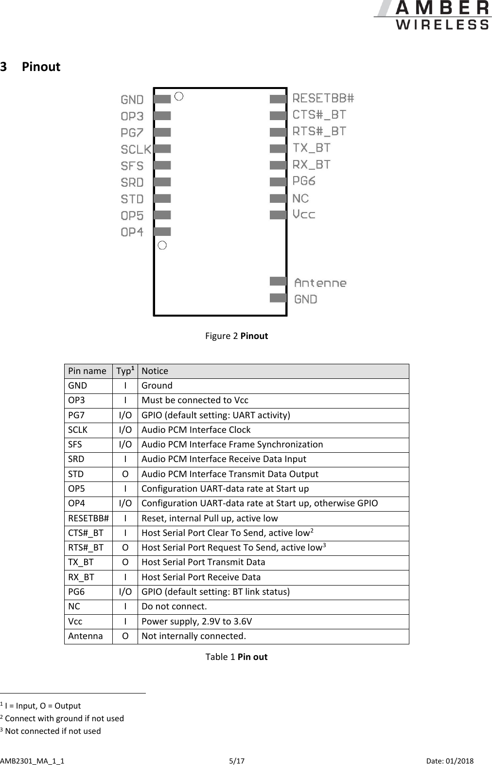
![AMB2301_MA_1_1 6/17 Date: 01/2018 3.1 Minimum connection to run the AMB2301 In order to realize a radio transmission, the following connections of the AMB2301 have to be wired: VCC, GND Power supply RX, TX UART data RTS, CTS UART handshake; if does not need: short RTS and CTS or contact CTS at GND (without flow control it can come to overrun and lost data) OP3 High (connect to VCC) OP4, OP5 Configuration UART, see chapter 2.2.3 (open or 1KΩ pull-up) All other pins don’t need to be connected. 3.2 Default settings All parameters are stored inside the internal EEPROM. See [1] and [2]. In the Bluetooth environment, the device announces itself as a XXXXXX (Device Name), whereas XXXXXX has to be replaced by the device’s Bluetooth address. 3.3 Detailed Description 3.3.1 UART configuration with OP4, OP5 The serial interface of the AMB2301 must be configured as follows: OP4 OP5 Function Open Open UART speed read from NVS (EEPROM) Open High UART speed 9.6 kbps High Open UART speed 115.2 kbps High High UART speed 921.6 kbps Caution: Use 1KOhm pull up for OP4 and OP5 High state. While power up OP4 and OP5 are pulled down internally. Using other resistor values might lead to malfunction. 3.3.2 UART interface RX_BT, TX_BT, RTS#_BT and CTS#_BT The interface serves for communication with the AMB2301. Hardware handshake is used (RTS/CTS). If this should not be supported by the host system, RTS#_BT and CTS#_BT must be short circuit or CTS#_BT put on Low levels. This can lead however to data loss due to overrun. Therefore it is recommended to use handshake. 3.3.3 Details to the remaining connections of the AMB2301 ResetBB# Internal Pull up, low active, no external pull up recommended SCLK, SFS, SRD, STD Audio interface, if not used, pins does not attached PG6, PG7 I/O ports, if not used, pins does not attached Vcc, Gnd Power supply 3.4 Commando Interface The AMB2301 based on LMX9830 provides a simple Commando Interface. Detailed Information can be found in the IC documentation [2]. To simplify the use of this commands further a PC tool, the “Simply Blue Commander” is available.](https://usermanual.wiki/Wuerth-Elektronik-eiSos-and-Co-KG/AMB2301/User-Guide-3755121-Page-6.png)
![AMB2301_MA_1_1 12/17 Date: 01/2018 6 References [1] LMX9830 Data Sheet [2] LMX9830 Software User’s Guide [3] Simply Blue Commander](https://usermanual.wiki/Wuerth-Elektronik-eiSos-and-Co-KG/AMB2301/User-Guide-3755121-Page-12.png)