Wuerth Elektronik eiSos and Co KG AMB2561 Low Power Transceiver User Manual Handbuch AMB8420 AMB2520
AMBER Wireless GmbH Low Power Transceiver Handbuch AMB8420 AMB2520
User manual

AMB2561_MA_V1_0 Page 2 of 11 Date: 03/2014
Table of Contents
1 Startup „Step-by-step“ ............................................................................................... 3
2 Using the USB-Stick with a terminal program .......................................................... 4
2.1 Example Terminal.exe ..................................................................................................... 4
3 Using the configuration software “ACC” .................................................................. 5
4 Disconnecting the DTR-Signal .................................................................................. 6
5 References .................................................................................................................. 7
6 Regulatory compliance information .......................................................................... 8
6.1 Important notice ............................................................................................................... 8
6.2 Declaration of conformity ........................................... Fehler! Textmarke nicht definiert.
7 Important Information .............................................................................................. 11
7.1 Exclusion of Liability ....................................................................................................... 11
7.2 Trademarks .................................................................................................................... 11
7.3 Usage Restriction ........................................................................................................... 11

AMB2561_MA_V1_0 Page 3 of 11 Date: 03/2014
1 Startup „Step-by-step“
1. Driver Installation
The first step of the startup procedure of the USB Stick is to install the driver for the
virtual COM Port.
Therefor the installation zip archive for the USB IC, namely the FT231XQ, first has to be
downloaded from the manufacturer website (FTDI [5]). Afterwards the extraction and
installation according to the displayed guidelines takes place until the installation has
successfully finished.
2. Plug in the USB-stick
Now the USB stick can be connected to a free USB slot on the pc, the red power LED
lights up. Windows automatically identifies the connected device. A Windows routine for
the allocation of the driver starts automatically.
3. Serial Port
The driver now creates a virtual serial port on your system with the following default port
settings:
38400 Baud, 8 data bits, no parity and 1 stop bit.
4. Using the stick
Now the USB-Stick can be accessed via serial port as described in the AMB2520
manual [1].
5. Demo program [2]
By the use two USB Sticks with the same RF settings (e.g. in default channel 79 /
2440,0MHz) and the demo program, it is possible to conduct a range measurement.
The Demo program uses the default settings of 38400 baud 8n1 on the COM interface.
For the range measurement the demo program has to be started for each USB stick
respectively (e.g. the first stick on a PC and the second Stick on a Laptop). The
corresponding COM-Port has to be opened.
If the sticks are operated in close proximity of each other it may occur that the receiver
amplifiers are overdriven which could result in failure of communication.
By clicking on the button “Toggle Mode” both modules are set into “Command Mode”. To
start the signal strength measurement click on “Start RSSI test” on one of the demo
programs.
If the progress bar under the button “Start RSSI test” makes no further progress you can
restart the measurement by a renewed click on “Start RSSI test”.
The stick has an internal LED to signal incoming data.
AMB2561_MA_V1_0 Page 4 of 11 Date: 03/2014
The detailed description of the configuration possibilities, operating modes,
commands, etc. can be found in the manual [1].
A “high” level on the DTR line holds the module in reset state.
Some terminal programs automatically set the DTR line to “high” when opening the
COM port, which prevents normal operation of the stick.
The signal level on the DTR line has to be set to “low”.
2 Using the USB-Stick with a terminal program
Since not all terminal programs offer the possibility to configure the DTR line, it has to be
mentioned that “Terminal.exe” is a program which does offer this necessary functionality. It can
be downloaded free of charge from [3].
2.1 Example Terminal.exe
The program can be started directly after haven been downloaded and extracted onto your PC,
without any further installation. In the upper left corner you can select the COM port (between
COM1 and COM20). If the stick is assigned to a higher port number by Windows, you may
follow the instructions under [4] to release COM ports that are not in use. Thereafter the
remaining settings can be selected (38400 Baud, 8n1, no handshaking), and the COM port may
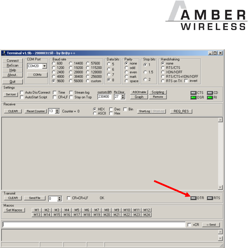
be opened by clicking the “Connect” button. By clicking on the DTR LED (see red arrow) it is
possible to switch the DTR line to “high” or to “low” (LED is gray). With DTR set to “low” the stick
is now able to transmit the data which is entered in the “send” field at the bottom. The received
data is displayed in the “Receive” field above.
AMB2561_MA_V1_0 Page 5 of 11 Date: 03/2014
Terminal program
3 Using the configuration software “ACC”
The configuration software AMBER Config Center, ACC, is available for registered users [6].
The connection process is shown below:
1. Connect the USB-Stick to a free slot on your PC.
2. Determine the associated COM-Port in the device manager.
3. Start the ACC software and enter the correct COM-Port.
4. Click on “Connect”.
…
AMB2561_MA_V1_0 Page 6 of 11 Date: 03/2014
5. Push “reset” button.
6. Now the module settings may be read and edited.
4 Disconnecting the DTR-Signal
If the reset functionality via the virtual COM port is not required or it causes problems with
certain applications, then this connection can quite easily be removed.
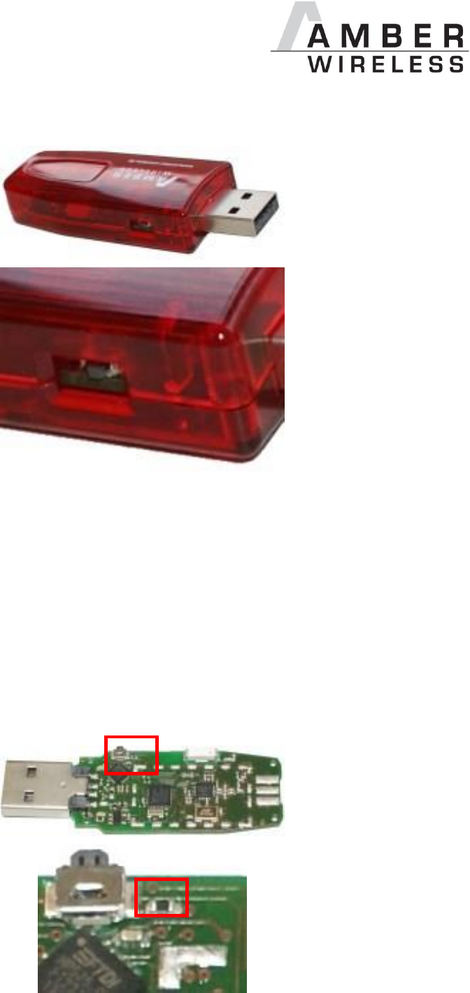
For this the housing of the USB-stick has to be opened first. Now the DTR signal can be
removed by desoldering one resistor (see picture below: package 0402). The reset button on
the stick is not affected by this procedure. Finally the housing may be closed again.

AMB2561_MA_V1_0 Page 7 of 11 Date: 03/2014
5 References
[1] Download “AMB8420_AMB2520_MA” on http://amber-
wireless.de/files/amb8420_2520_ma.pdf (Stand 29.01.14)
[2] Download “AMB8460 + AMB2560 Tools” http://amber-
wireless.de/files/amb2560_amb8460_tools.zip (Stand 29.01.14)
[3] https://sites.google.com/site/terminalbpp/
[4] Download “AN02_COM-PORT_loeschen” on http://amber-wireless.de/files/an02_com-
port_loeschen.pdf (Stand 29.01.14)
[5] Download on http://www.ftdichip.com/Drivers/VCP.htm (Date: 29.01.14)
[6] Download “ACC Software” on http://amber-wireless.de/files/acc.zip (Date: 29.01.14)

AMB2561_MA_V1_0 Page 8 of 11 Date: 03/2014
6 Regulatory compliance information
6.1 Important notice
The use of RF frequencies is limited by national regulations. The AMB2561(-1) has been
designed to comply with the R&TTE directive 1999/5/EC of the European Union (EU).
The AMB2561(-1) can be operated without notification and free of charge in the area of the
European Union. However, according to the R&TTE directive, restrictions (e.g. in terms of duty
cycle or maximum allowed RF power) may apply.
AMB2561(-1) Exemption clause
Relevant regulation requirements are subject to change. AMBER wireless GmbH does not
guarantee the accuracy of the before mentioned information. Directives, technical standards,
procedural descriptions and the like may be interpreted differently by the national authorities.
Equally, the national laws and restrictions may vary with the country. In case of doubt or
uncertainty, we recommend that you consult with the authorities or official certification
organizations of the relevant countries. AMBER wireless GmbH is exempt from any
responsibilities or liabilities related to regulatory compliance.

AMB2561_MA_V1_0 Page 9 of 11 Date: 03/2014
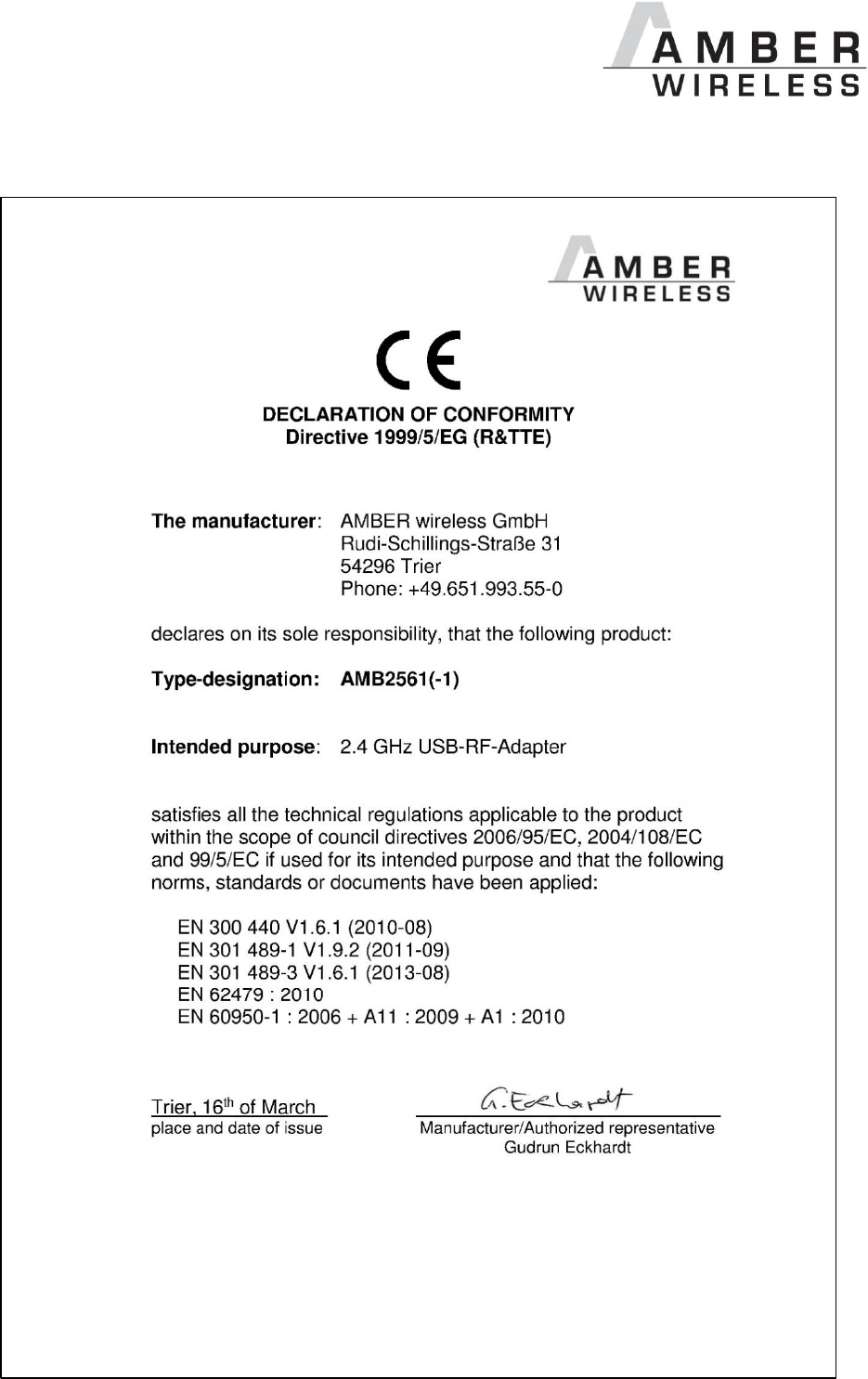
6.2 FCC statement
FCC ID: R7TAMB2561
This device complies with Part 15 of the FCC Rules. Operation is subject to the
following two conditions: (1) this device may not cause harmful interference, and (2)
this device must accept any interference received, including interference that may
cause undesired operation. (FCC 15.19)
Radio Frequency Interference (FCC 15.105)
This equipment has been tested and found to comply with the limits for Class B digital devices
pursuant to part 15 of the FCC Rules. These limits are designed to provide reasonable
protection against harmful interference in a residential installation. This equipment generates,
uses and can radiate radio frequency energy and, if not installed and used in accordance with
the instructions, may cause harmful interference to radio communications. However, there is no
guarantee that interference will not occur in a particular installation. If this equipment does
cause harmful interference to radio or television reception, which can be determined by turnin
the equipment off and on, the user is encouraged to try to correct the interference by one or
more of the following measures:
- Reorient or relocate the receiving antenna.
- Increase the separation between the equipment and receiver.
- Connect the equipment into an outlet on a circuit different from that to which the receiver
is connected.
- Consult the dealer or an experienced radio/TV technician for help.
Modifications (FCC 15.21)
Caution: Changes or modifications for this equipment not expressly approved by AMBER
wireless may void the user’s authority to operate this equipment.
AMB2561_MA_V1_0 Page 10 of 11 Date: 03/2014
6.3 Declaration of Conformity
AMB2561_MA_V1_0 Page 11 of 11 Date: 03/2014
7 Important Information
7.1 Exclusion of Liability
AMBER wireless GmbH presumes that the information in this document is correct at the time of
publication. However, AMBER wireless GmbH reserves the right to modify technical
specifications or functions of its products or discontinue the production of these products or the
support of one of these products without any written announcement or notification to customers.
The customer must make sure that the information used is valid. AMBER wireless GmbH does
not assume any liability for the use of its products. Amber wireless GmbH does not grant
licenses for its patent rights or for any other of its intellectual property rights or third-party rights.
Customers bear responsibility for compliance of systems or units in which AMBER wireless
products are integrated with applicable legal regulations.
7.2 Trademarks
AMBER wireless® is a registered trademark of AMBER wireless GmbH.
All other trademarks, registered trademarks, and product names are the exclusive property of
the respective owners.
7.3 Usage Restriction
AMBER wireless products are not approved for use in life-supporting or life-sustaining systems
or units or other systems whose malfunction could result in serious bodily injury to the user.
Moreover, AMBER wireless products are not approved for use as key components of any life-
supporting or life-sustaining system or unit whose malfunction could result in the failure of the
life-supporting system or unit or could affect its safety or effectiveness. AMBER wireless
customers who use these products in such applications or sell them for such usage act at their
own risk and must relieve AMBER wireless GmbH from all damages that may result from the
sale for unsuitable purposes or unsuitable usage.
By using AMBER wireless products, the user agrees to these terms and conditions.
© 2015, AMBER wireless GmbH. All rights reserved.
AMBER wireless GmbH
Phone +49.651.993.550
Email info@amber-wireless.de
Internet www.amber-wireless.de
