Wuerth Elektronik eiSos and Co KG AMB9625 AMB9625 User Manual
AMBER Wireless GmbH AMB9625 Users Manual
UserManual.wiki
>
Wuerth Elektronik eiSos and Co KG
>
AMB9625 User Manual
Users Manual
Navigation menu
Upload a User Manual
Namespaces
Wiki Guide
HTML
PDF
Info
Views
User Manual
Discussion / Help
Navigation
![AMB9625_MA_1_0 Page 5 of 107 Date: 09/2017 Abbreviations and abstract ACK Acknowledgement Acknowlegdement pattern confirming the reception of the transmitted data package CS Checksum DC Duty cycle Relative frequency reservation period LPM Low power mode Operation mode for efficient power consumption. RF Radio frequency Describes everything relating to the wireless transmission Payload The real, non-redundant information in a frame/packet User settings Any relation to a specific entry in the user settings is marked in a special font and can be found in the respective chapter UART Universal Asynchronous Receiver Transmitter, allows to communicate with the module of a specific interface. Duty cycle Transmission time in relation of one hour 1% means, channel is occupied for 36 seconds per hour. Hexadecimal [HEX] 0xhh All numbers beginning with 0x are stated as hexadecimal numbers. All other numbers are decimal.](https://usermanual.wiki/Wuerth-Elektronik-eiSos-and-Co-KG/AMB9625/User-Guide-3598987-Page-5.png)
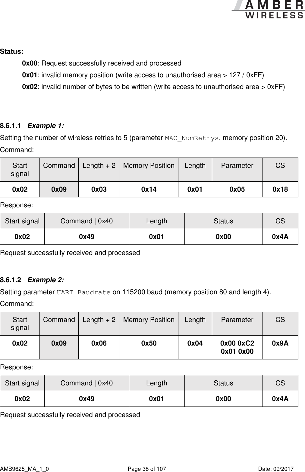
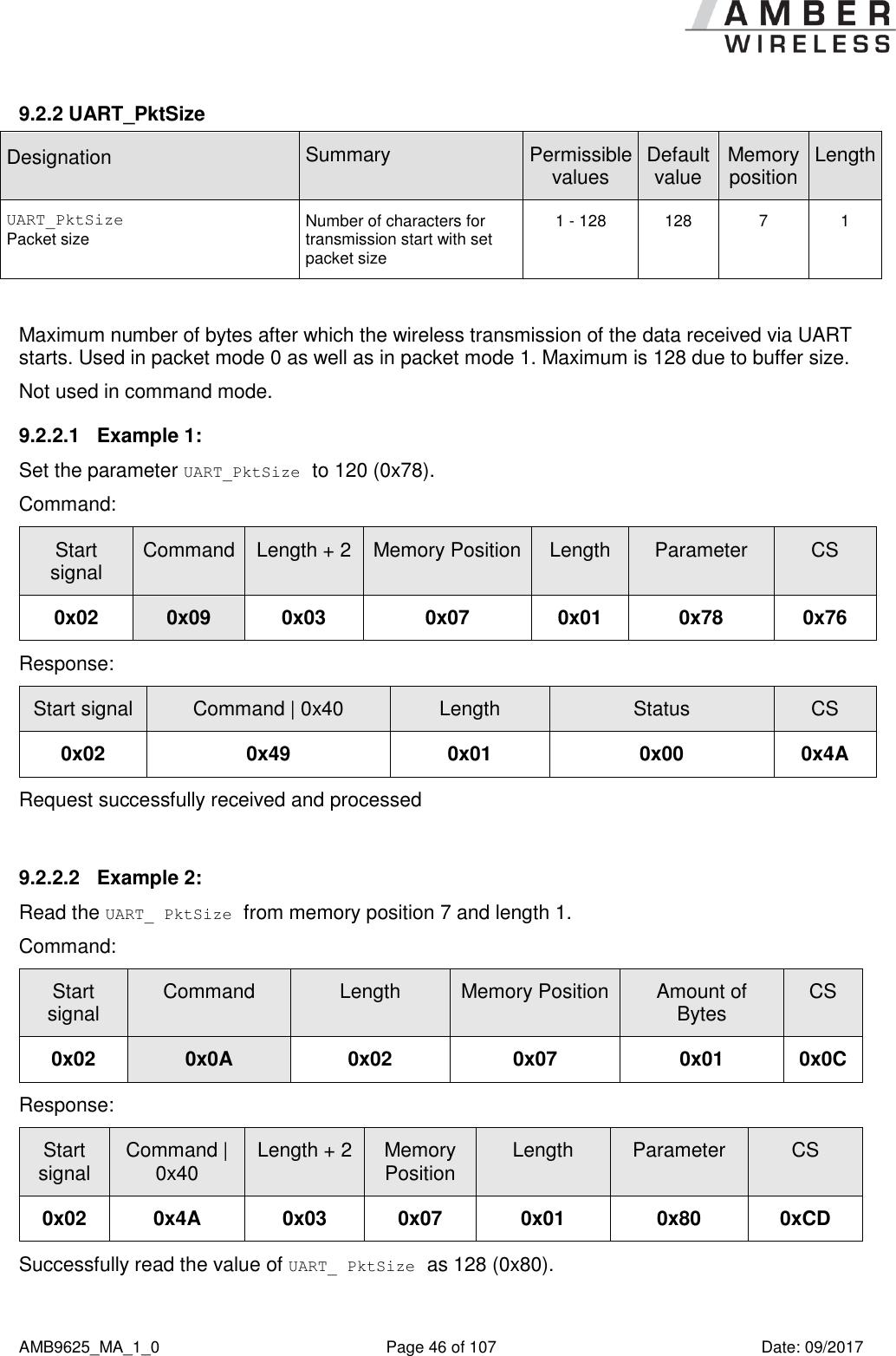
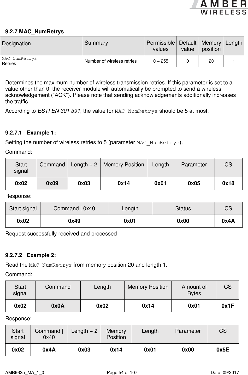
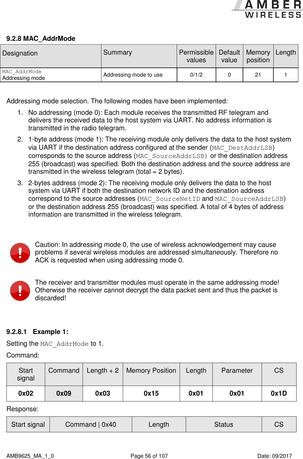
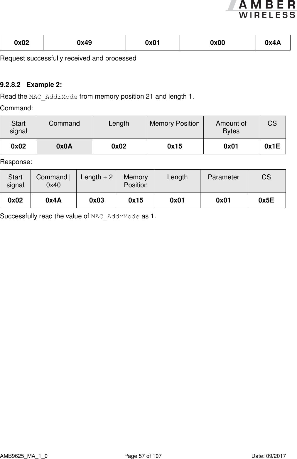
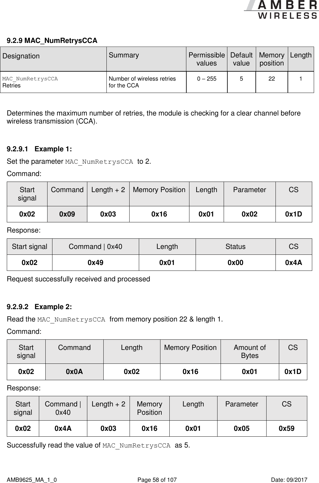
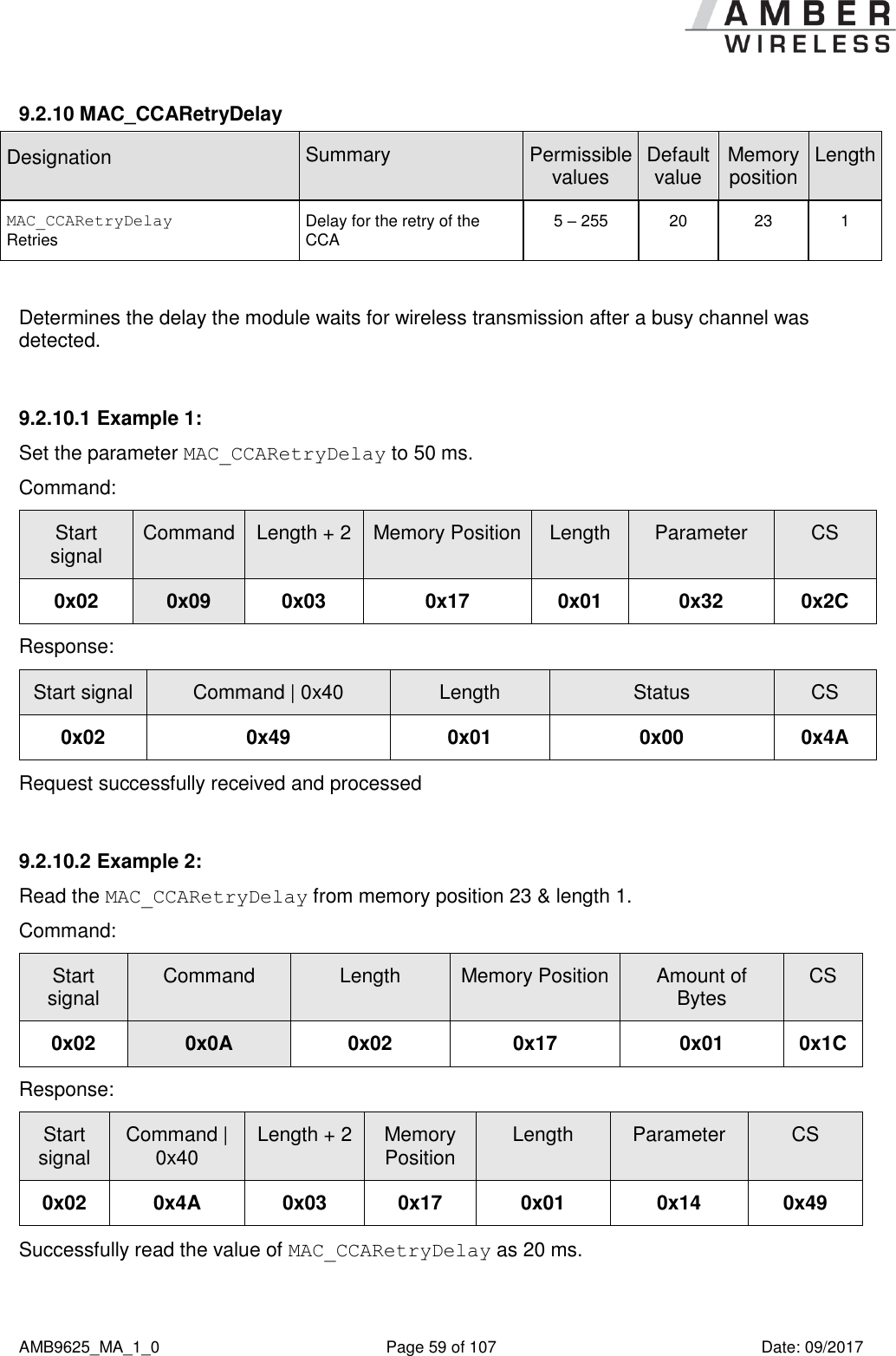
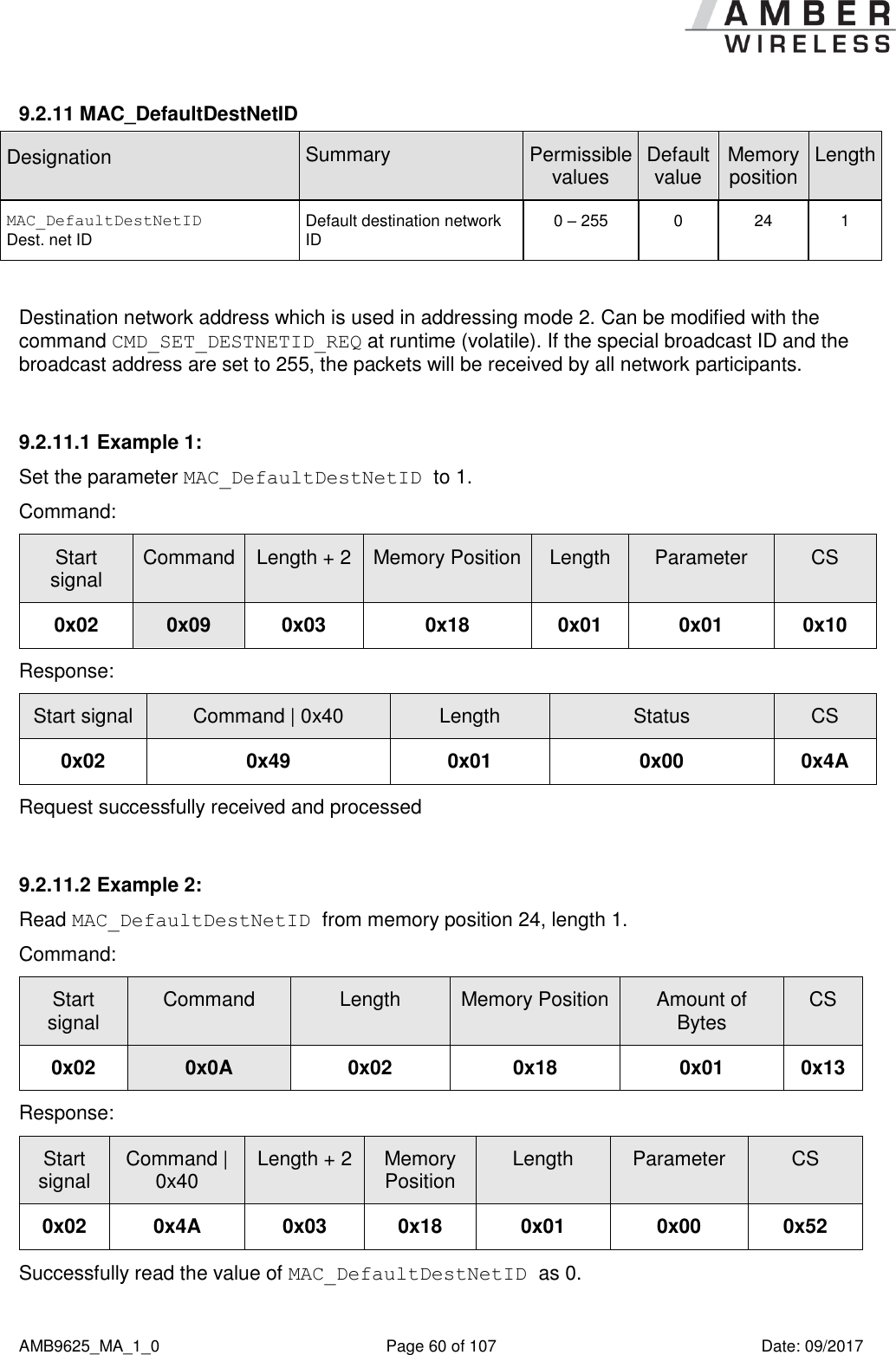
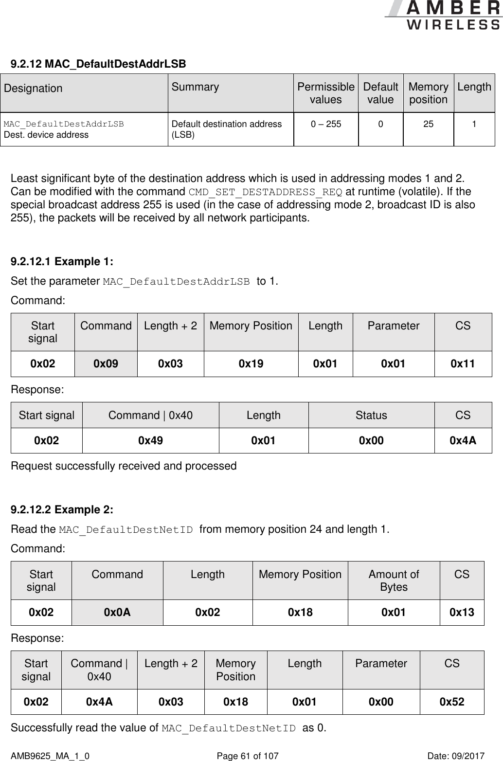
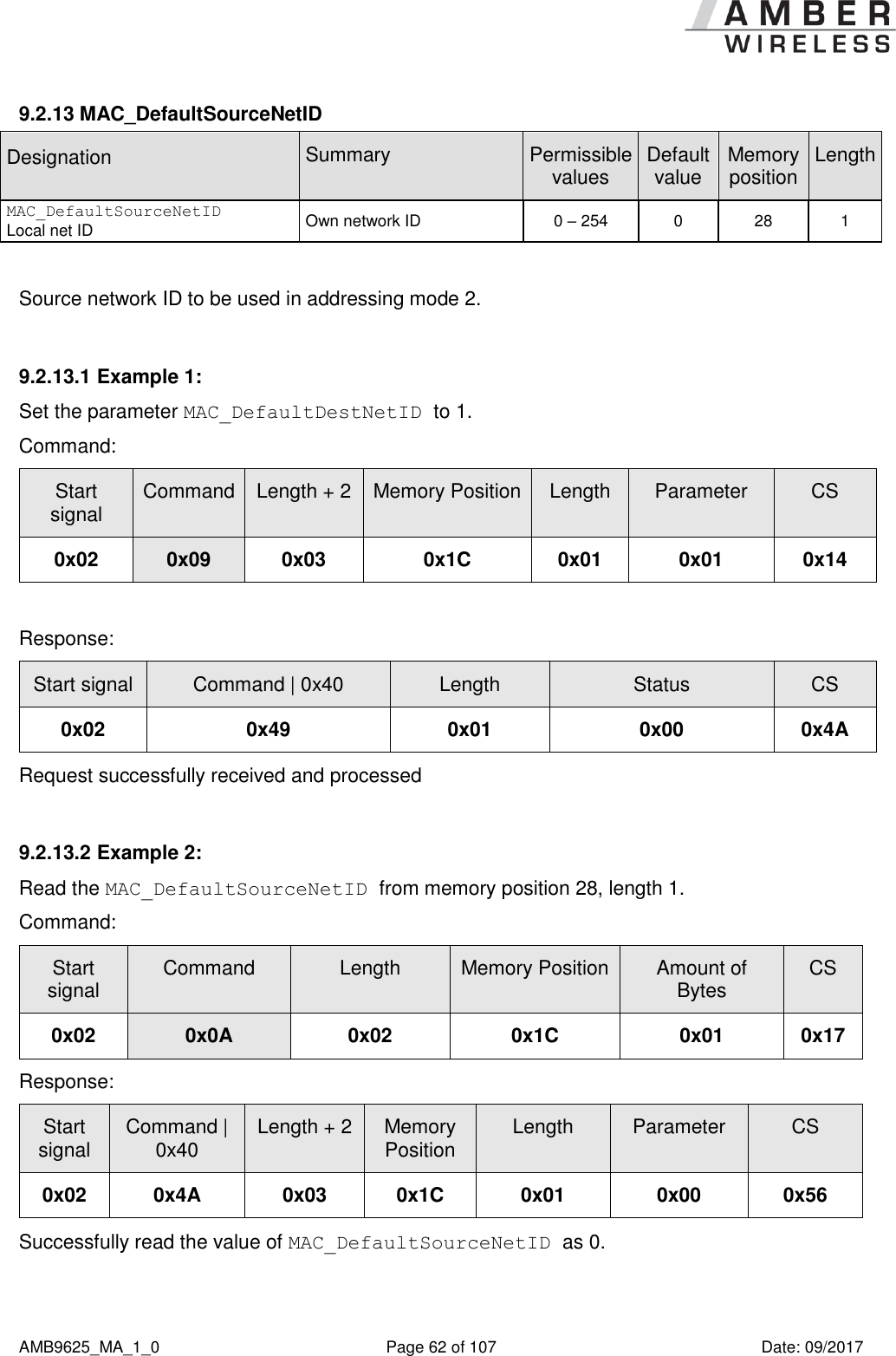
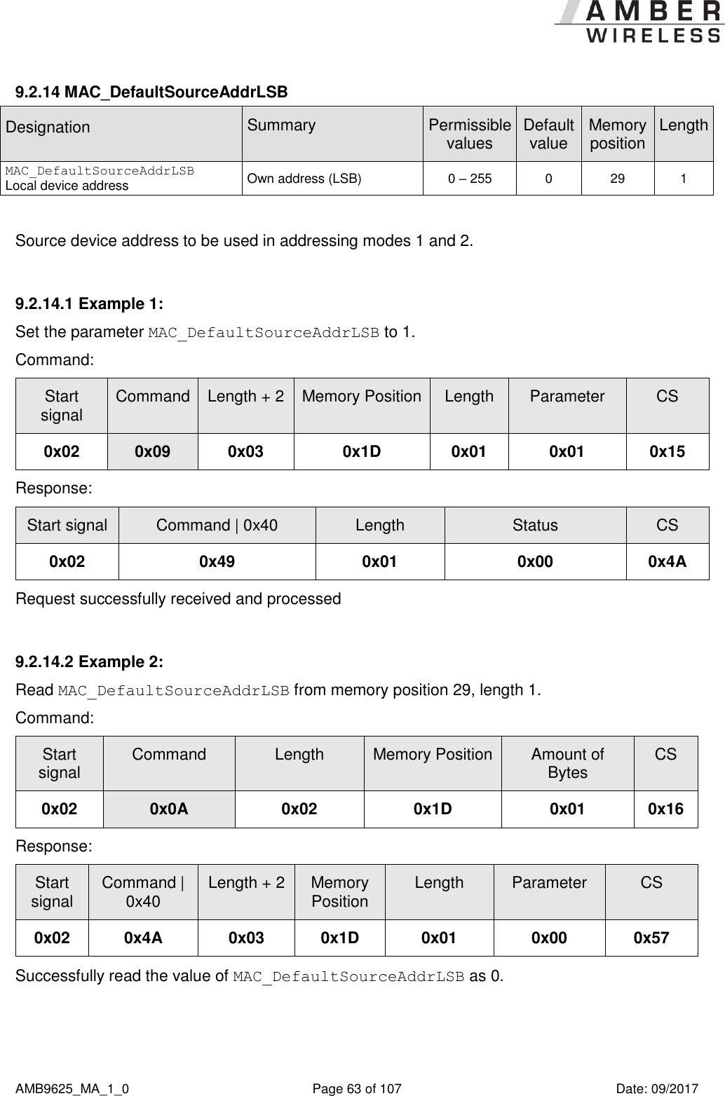
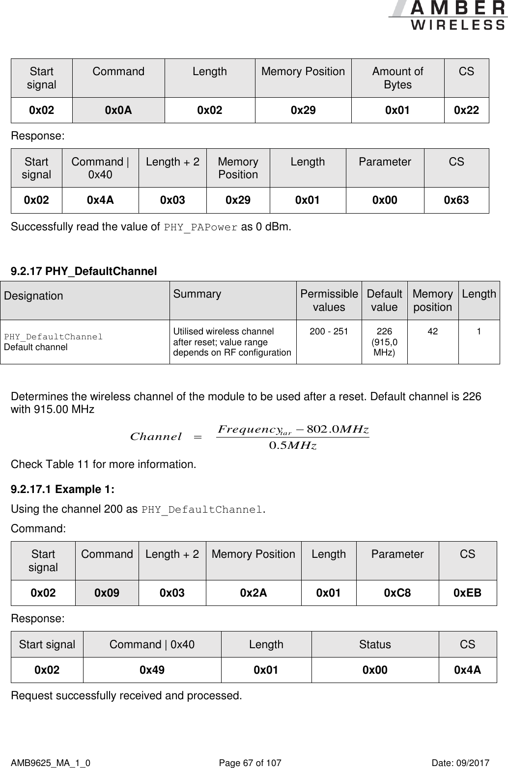
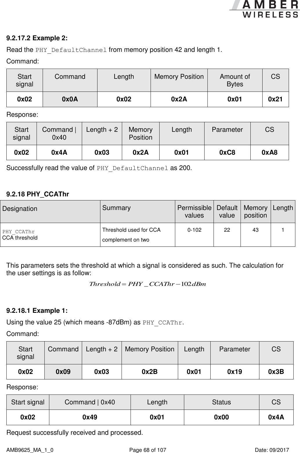
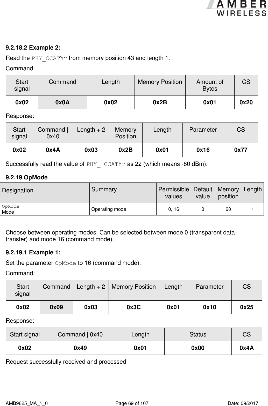
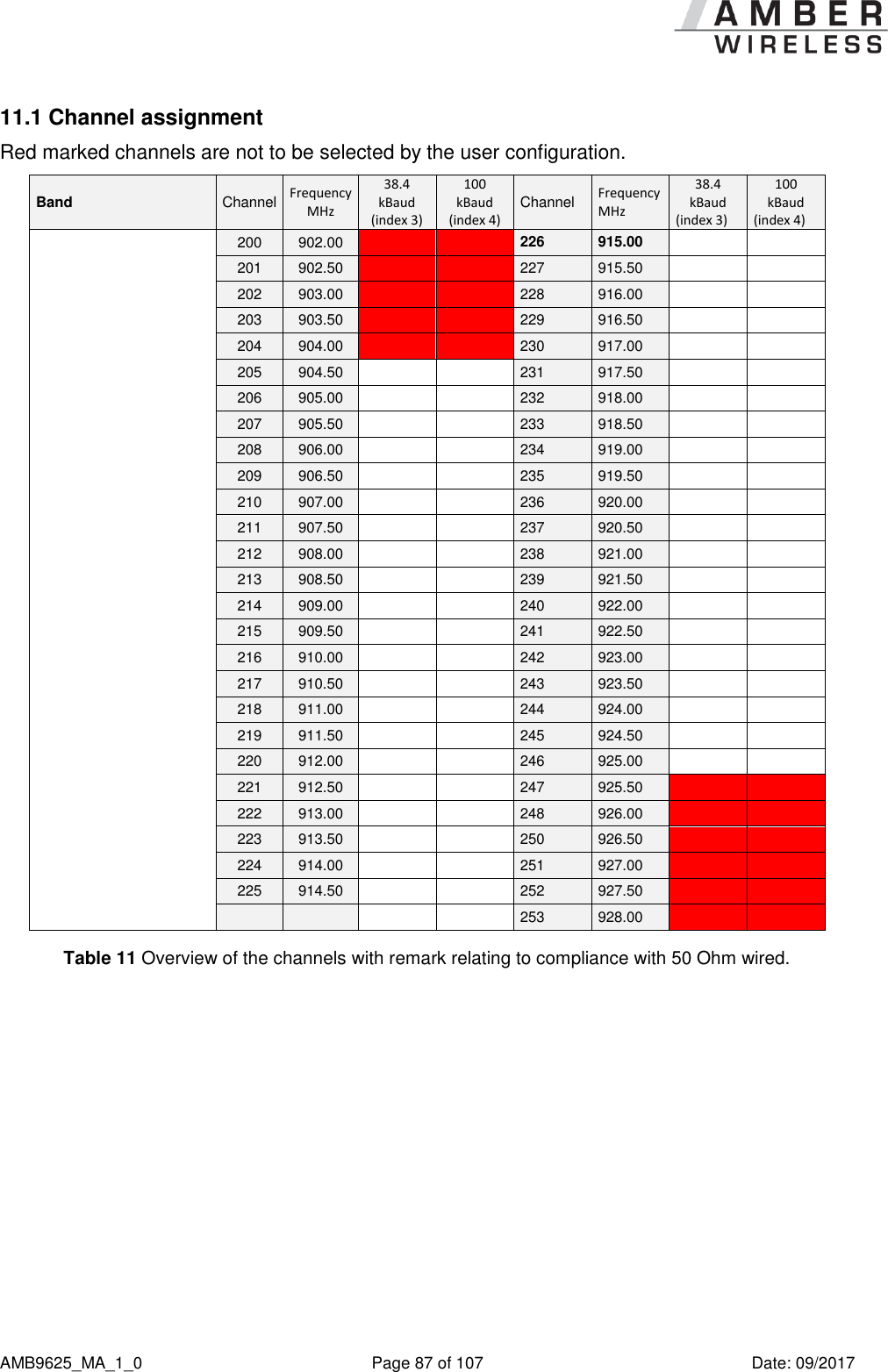
![AMB9625_MA_1_0 Page 42 of 107 Date: 09/2017 Designation Summary Permissible values Default value Memory position Length UART_Timeout Timeout Timeout after the last character before the data received via UART are transmitted via wireless transmission [ms] 2 – 65535 5 12 2 UART_DIDelay Data Indication Delay Delay between signal by Pin /DATA_INDICATION and beginning of output by UART [ms] 0 – 65535 0 14 2 MAC_NumRetrys Retries Number of wireless retries 0 – 255 0 20 1 MAC_AddrMode Addressing mode Addressing mode to use 0/1/2 0 21 1 MAC_NumRetrysCCA Retries Number of wireless retries for the CCA 0 – 255 5 22 1 MAC_CCARetryDelay Retries Delay for the retry of the CCA 5 – 255 20 23 1 MAC_DefaultDestNetID Dest. net ID Default destination network ID 0 – 255 0 24 1 MAC_DefaultDestAddrLSB Dest. device address Default destination address (LSB) 0 – 255 0 25 1 MAC_DefaultDestAddrMSB Dest. device address Default destination address (MSB) 0 – 255 0 26 1 MAC_DefaultSourceNetID Local net ID Own network ID 0 – 254 0 28 1 MAC_DefaultSourceAddrLSB Local device address Own address (LSB) 0 – 255 0 29 1 MAC_DefaultSourceAddrMSB Local device address Own address (MSB) 0 – 255 0 30 1 MAC_ACKTimeout ACK timeout Waiting time for wireless acknowledgement [ms] 5 – 65535 10 32 2 PHY_PAPower PA power Output power [dBm]; value range depends on RF configuration complement on two -11 …+15 2 41 1 PHY_DefaultChannel Default channel Utilised wireless channel after reset; value range depends on RF configuration 201 - 250 226 (915,000 MHz) 42 1 PHY_CCAThr CCA threshold Threshold used for CCA complement on two 0-102 22 43 1 OpMode Mode Operating mode 0, 16 0 60 1](https://usermanual.wiki/Wuerth-Elektronik-eiSos-and-Co-KG/AMB9625/User-Guide-3598987-Page-42.png)
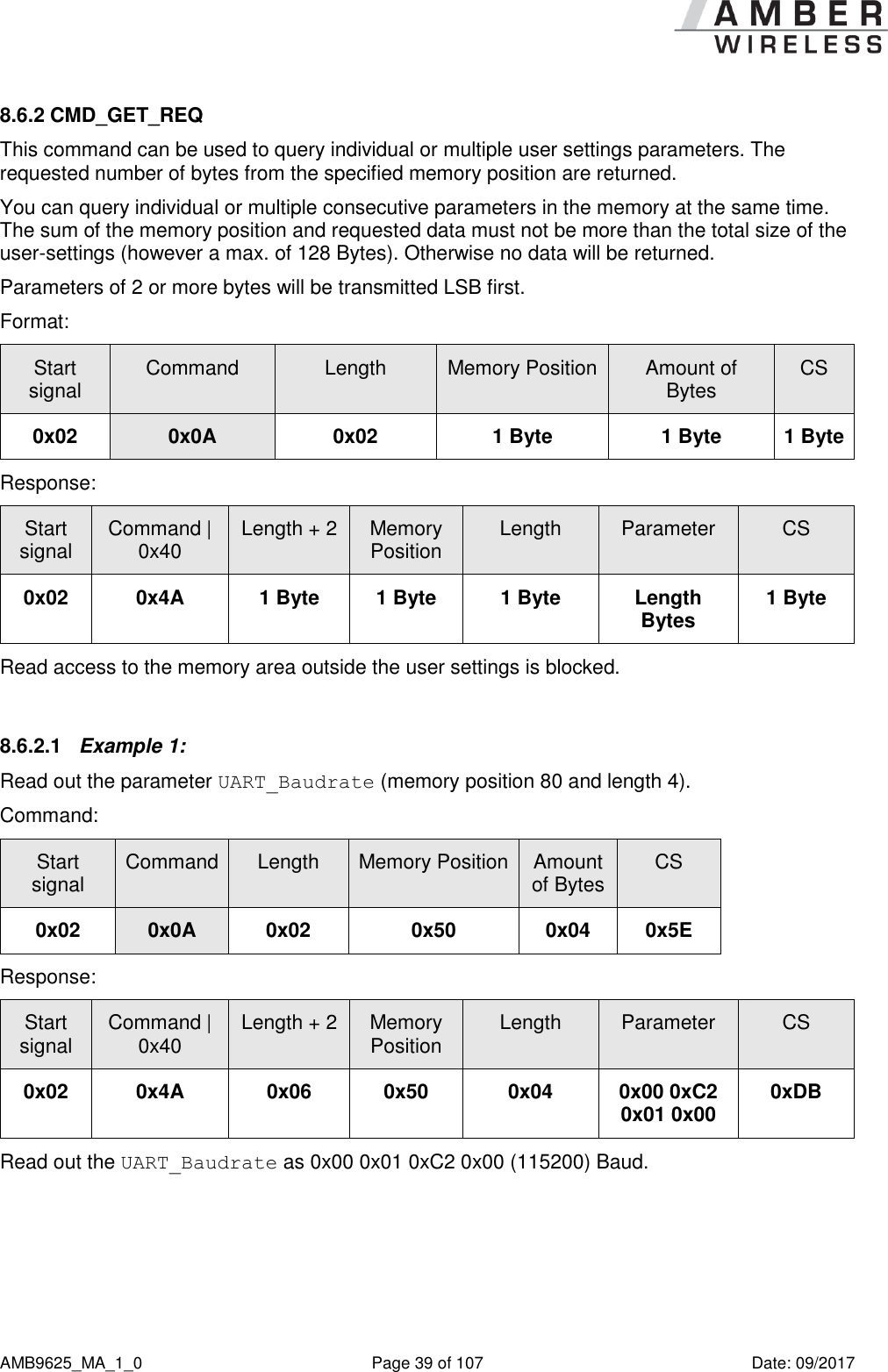
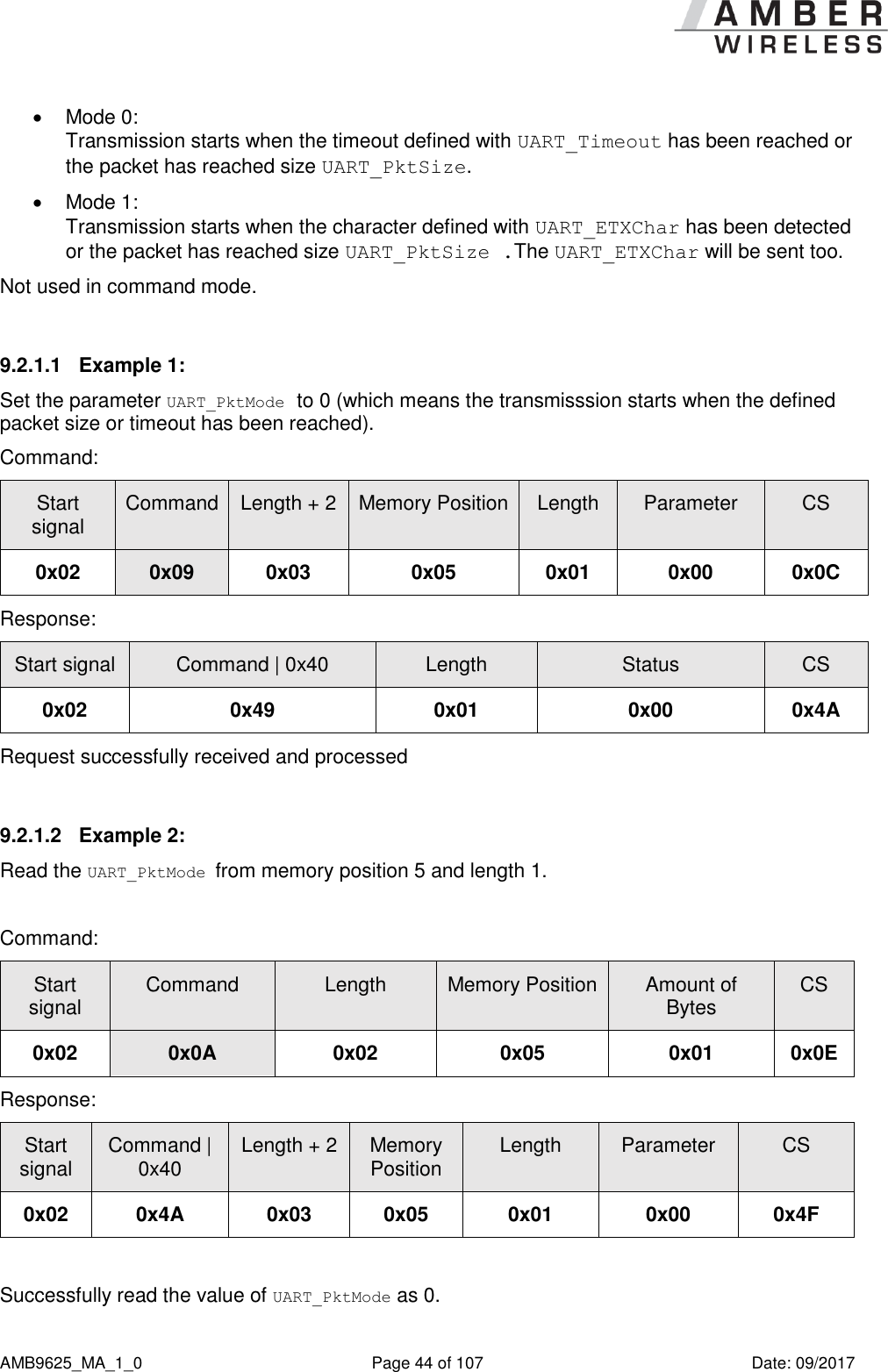
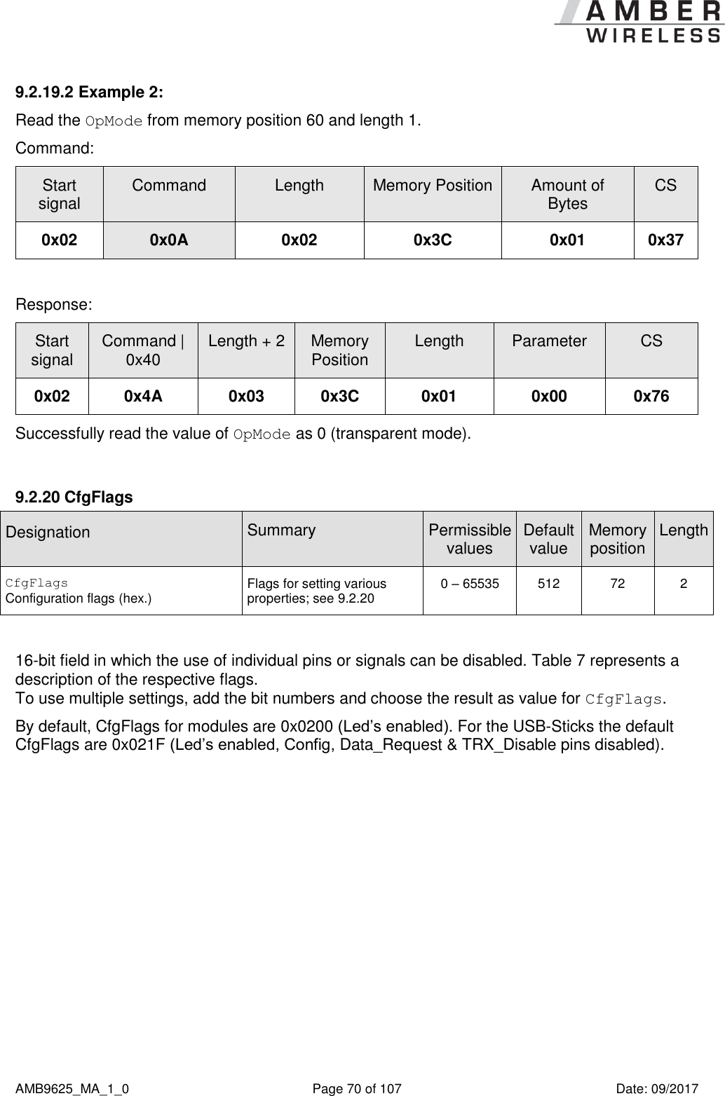
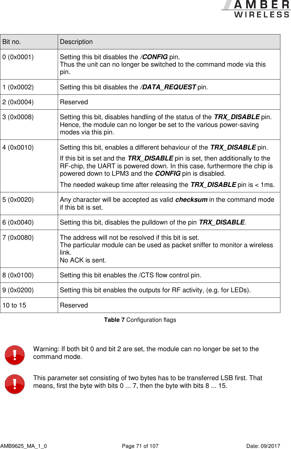
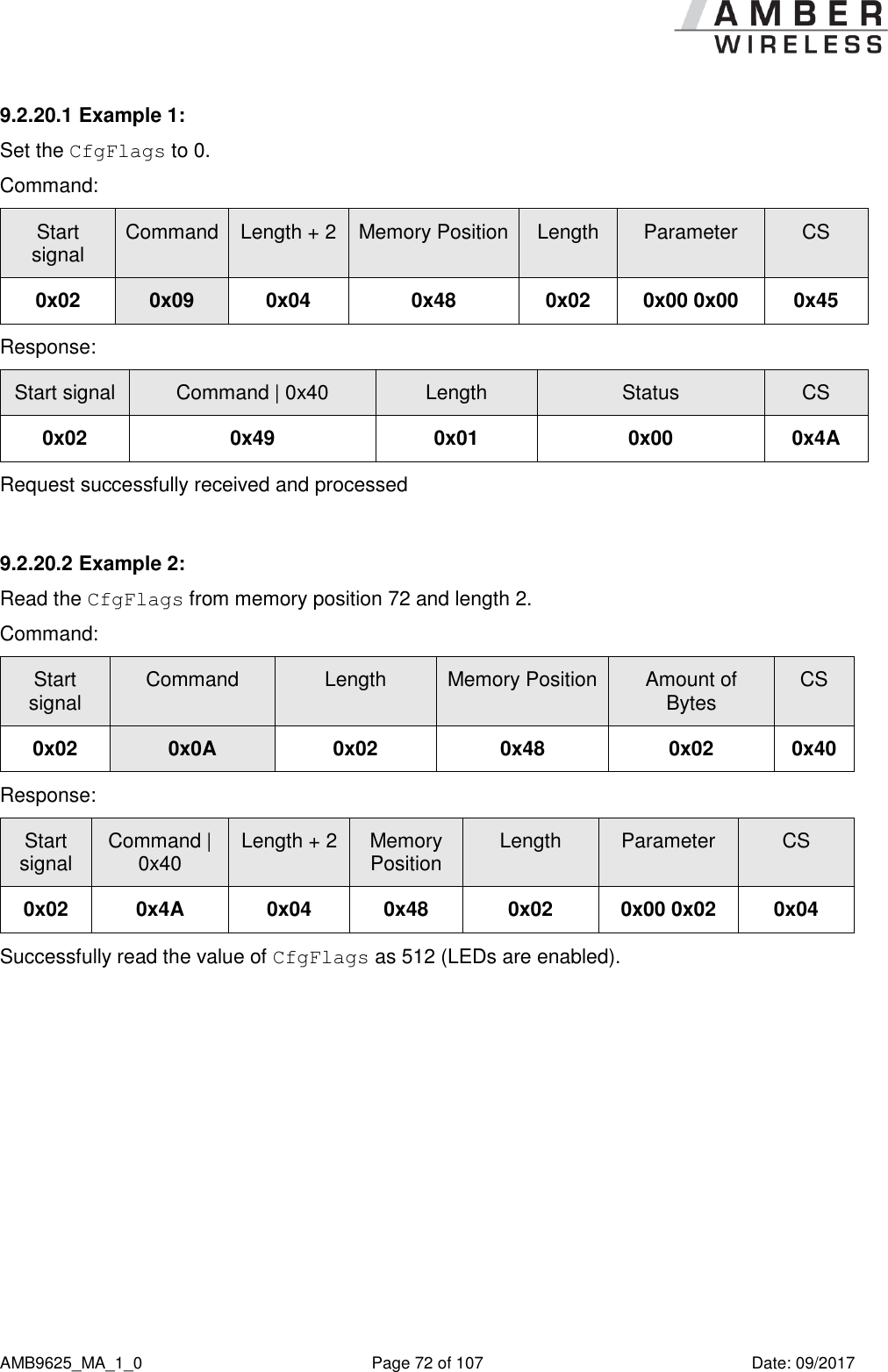
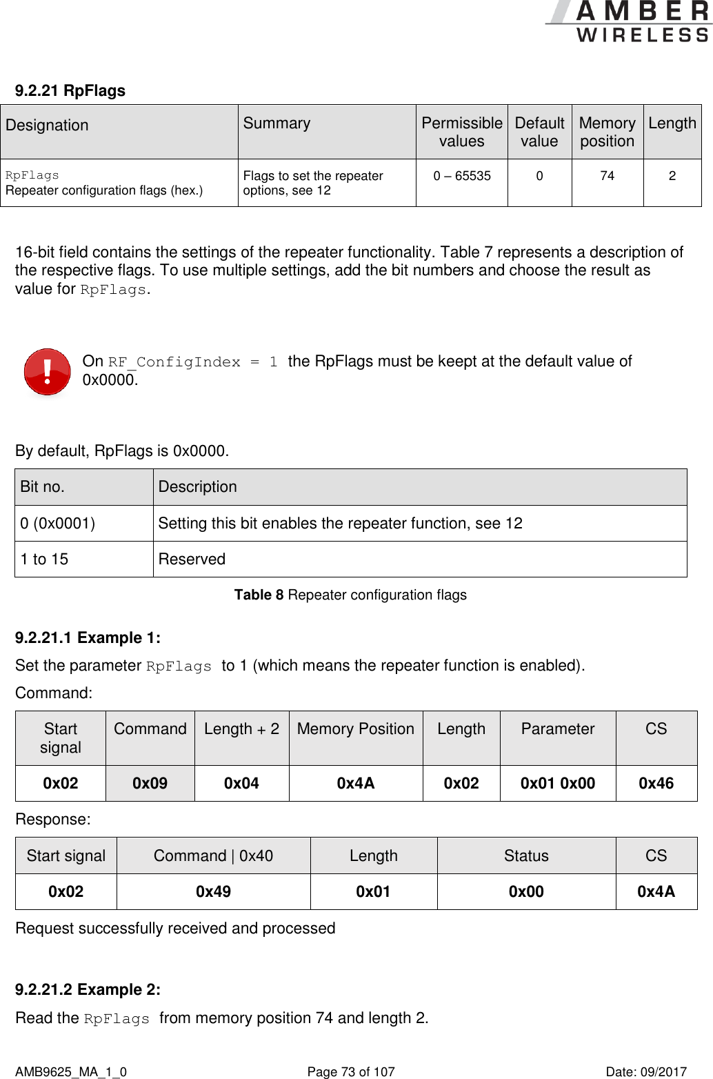
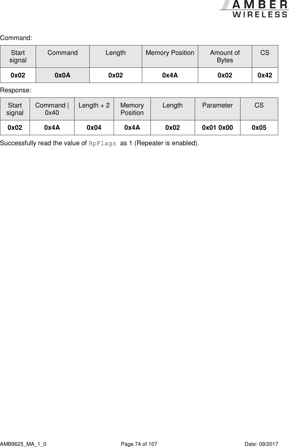
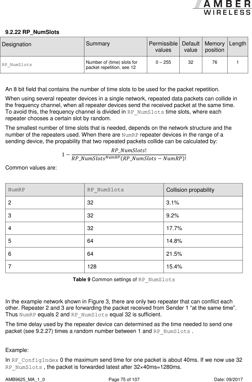
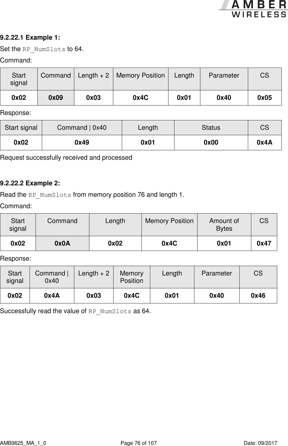
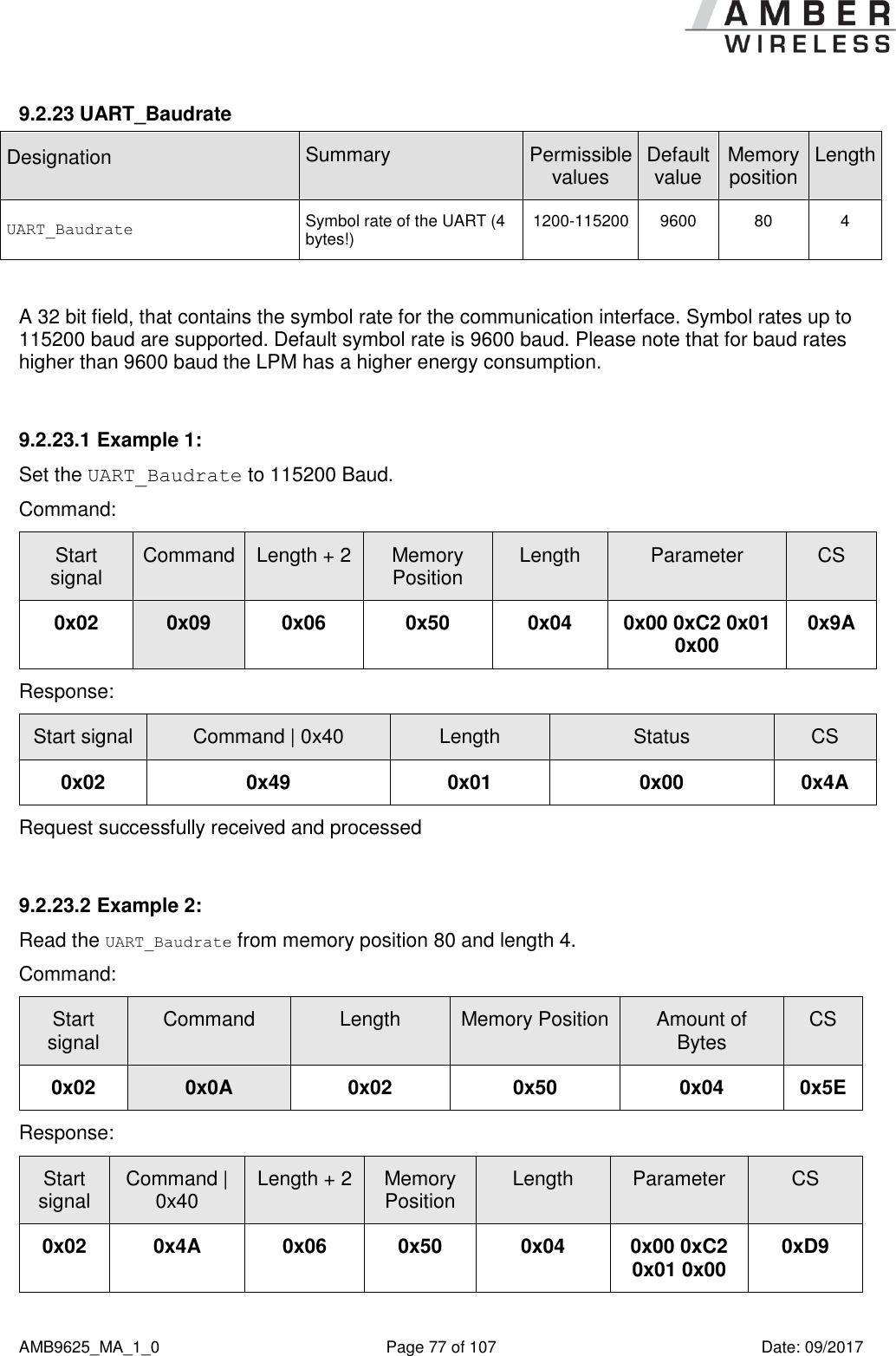
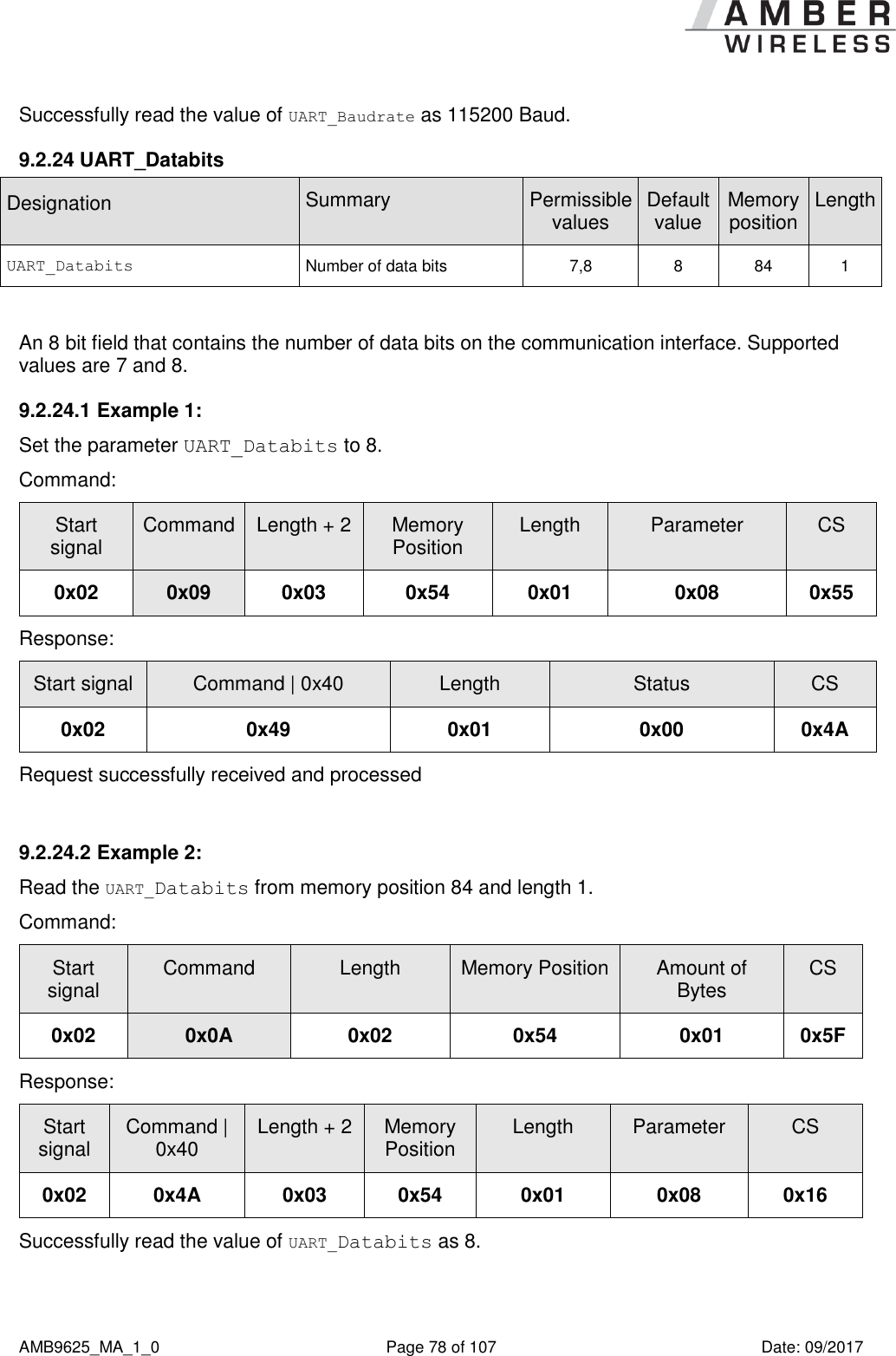
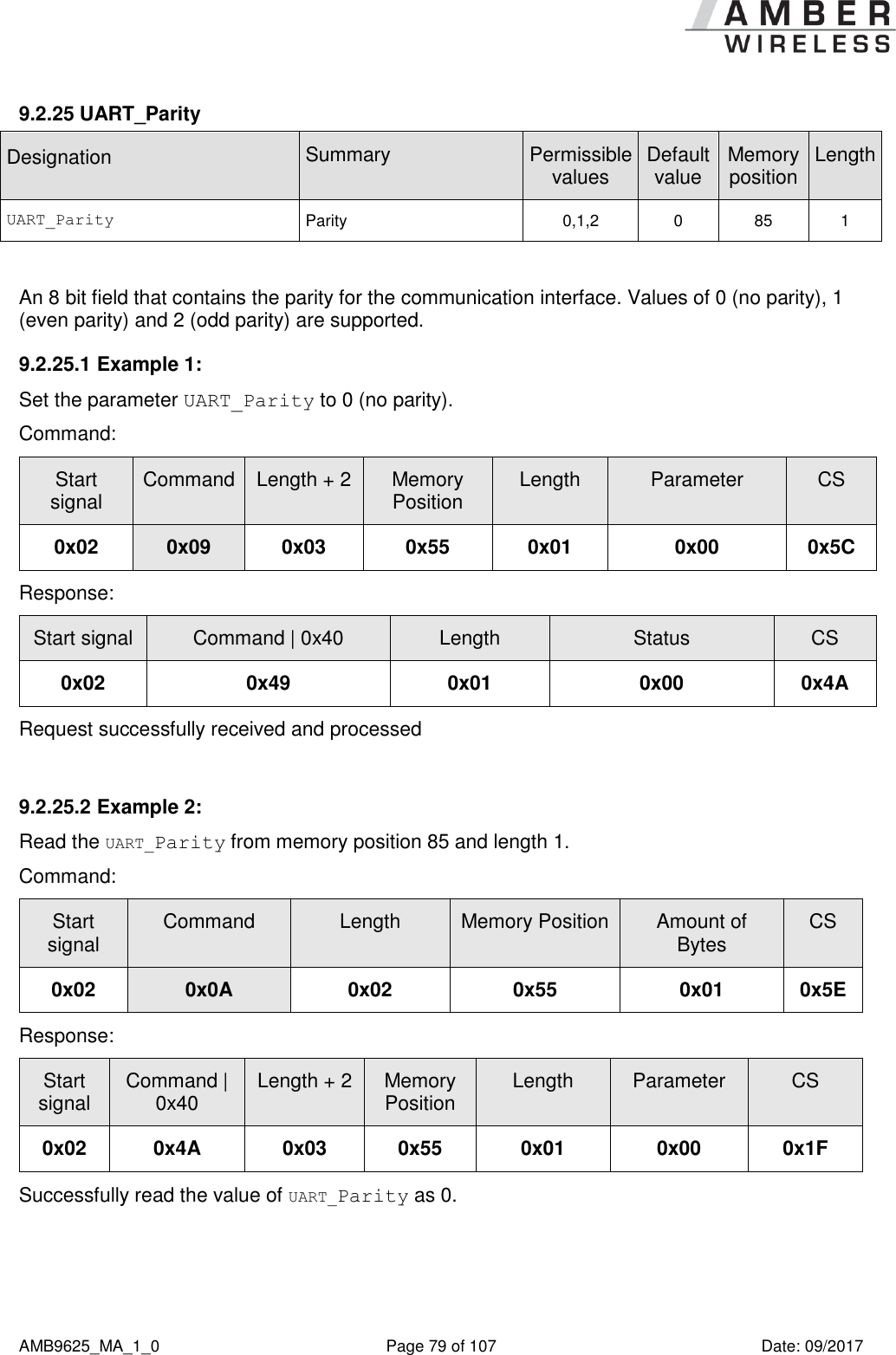
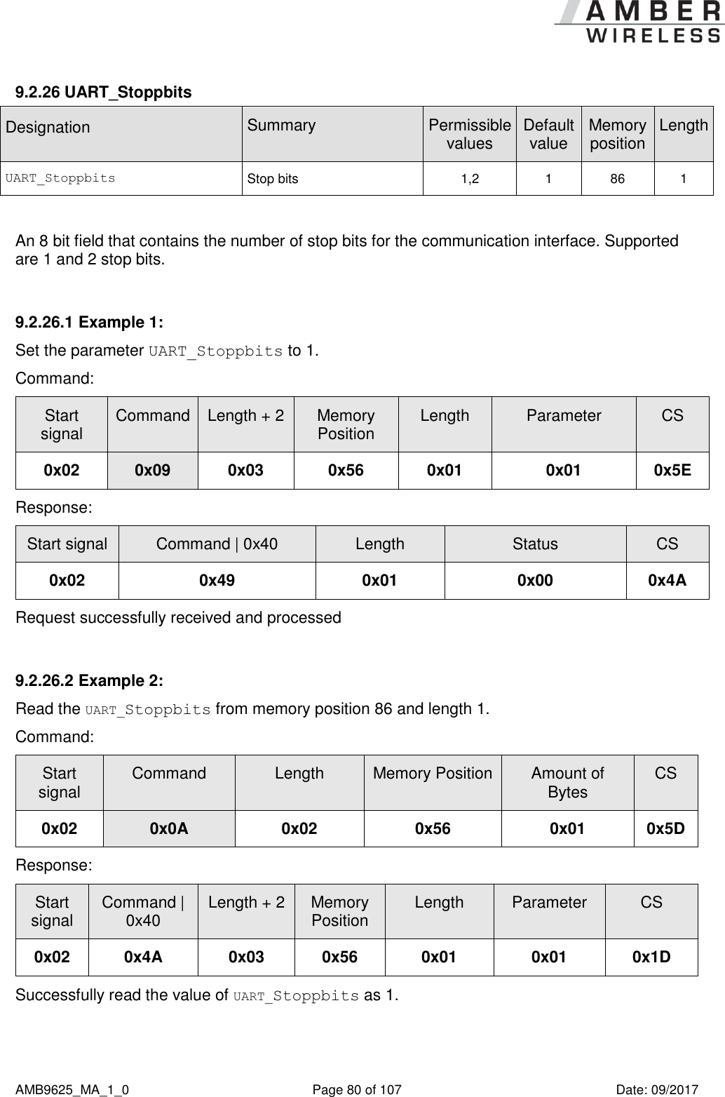
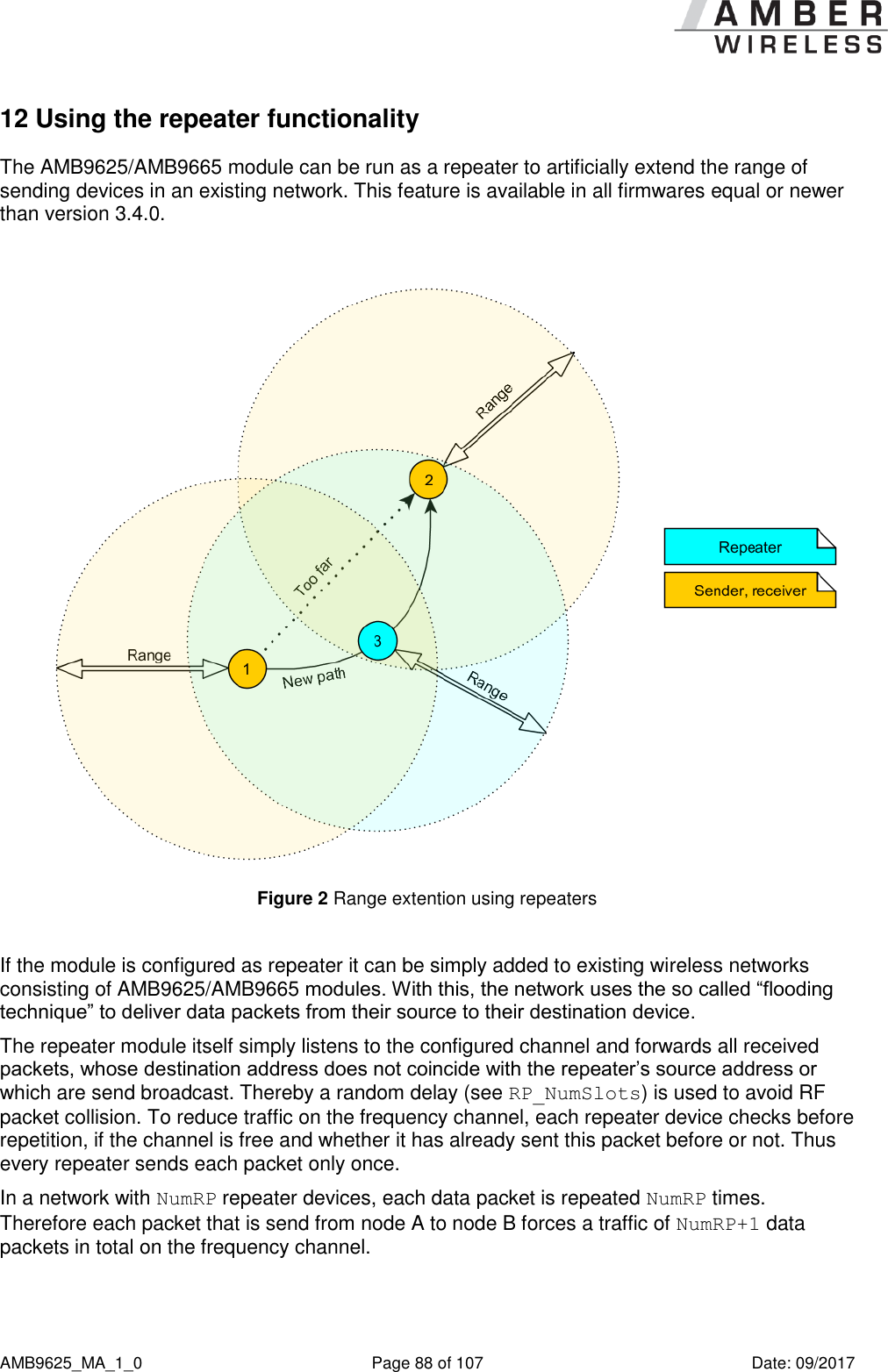
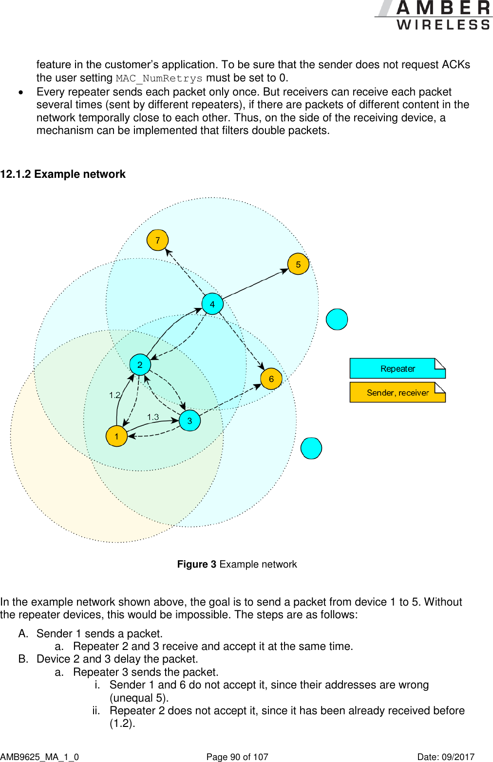
![AMB9625_MA_1_0 Page 43 of 107 Date: 09/2017 Designation Summary Permissible values Default value Memory position Length CfgFlags Configuration flags (hex.) Flags for setting various properties; see 9.2.20 0 – 65535 512 72 2 RpFlags Repeater configuration flags (hex.) Flags to set the repeater options, see 12 0 – 65535 0 74 2 RP_NumSlots Number of (time) slots for packet repetition, see 12 0 – 255 32 76 1 UART_Baudrate Symbol rate of the UART (4 bytes!) 1200-115200 9600 80 4 UART_Databits Number of data bits 7,8 8 84 1 UART_Parity Parity 0,1,2 0 85 1 UART_Stoppbits Stop bits 1,2 1 86 1 RF_ConfigIndex Configuration index 3 3 92 1 RF_CCADisabled Clear channel assessment 0,1 1 93 1 RF_CCACheckTime LSB (Index 95) und MSB(Index 96) Observation time [ms] 0-60000 5 94 2 Table 5 Overview of Non-Volatile user-settings Compared to the AMB8425/AMB8426, the following user settings are no longer implemented: - UART_CTL0, UART_CTL1 - UART_MCTL, UART_BR0, UART_BR1 - PHY_FIFOPrecharge, PHY_CCARSSILevel - MSP_RSELx - WOR_Prescaler, WOR_Countdown, WOR_RXOnTime - Synch1, Synch0 9.2.1 UART_PktMode Designation Summary Permissible values Default value Memory position Length UART_PktMode Packetizing mode Selects the packet generation method 0 or 1 0 5 1 Selects the packet mode used for generating packets for the transparent operating mode. In command mode the packet end is defined by the length information in the packet header. Two modes have been implemented:](https://usermanual.wiki/Wuerth-Elektronik-eiSos-and-Co-KG/AMB9625/User-Guide-3598987-Page-43.png)


![AMB9625_MA_1_0 Page 50 of 107 Date: 09/2017 9.2.5 UART_Timeout Designation Summary Permissible values Default value Memory position Length UART_Timeout Timeout Timeout after the last character before the data received via UART are transmitted via wireless transmission [ms] 2 – 65535 5 12 2 The timeout defines the delay in milliseconds in transparent mode after the last character has been received by the UART before the wireless transmission starts. Only used in packet mode 0. The value should be chosen appropriate to the UART data rate. 9.2.5.1 Example 1: Set the parameter UART_Timeout to 10. Command: Start signal Command Length + 2 Memory Position Length Parameter CS 0x02 0x09 0x04 0x0C 0x02 0x0A 0x00 0x0B Response: Start signal Command | 0x40 Length Status CS 0x02 0x49 0x01 0x00 0x4A Request successfully received and processed 9.2.5.2 Example 2: Read the UART_Timeout from memory position 12 and length 2. Command: Start signal Command Length Memory Position Amount of Bytes CS 0x02 0x0A 0x02 0x0C 0x02 0x04 Response: Start signal Command | 0x40 Length + 2 Memory Position Length Parameter CS 0x02 0x4A 0x04 0x0C 0x02 0x05 0x00 0x47](https://usermanual.wiki/Wuerth-Elektronik-eiSos-and-Co-KG/AMB9625/User-Guide-3598987-Page-50.png)
![AMB9625_MA_1_0 Page 52 of 107 Date: 09/2017 9.2.6 UART_DIDelay Designation Summary Permissible values Default value Memory position Length UART_DIDelay Data Indication Delay Delay between signal by Pin /DATA_INDICATION and beginning of output by UART [ms] 0 – 65535 0 14 2 This parameter determines the delay in milliseconds between the indication of incoming RF data by the /DATA_INDICATION pin and the output of the data on UART. This delay can be used to alert a sleeping host system to prepare for the reception of data. 9.2.6.1 Example 1: Set the parameter UART_DIDelay to 5. Command: Start signal Command Length + 2 Memory Position Length Parameter CS 0x02 0x09 0x04 0x0E 0x02 0x05 0x00 0x06 Response: Start signal Command | 0x40 Length Status CS 0x02 0x49 0x01 0x00 0x4A Request successfully received and processed 9.2.6.2 Example 2: Read the UART_ DIDelay from memory position 14 and length 2. Command: Start signal Command Length Memory Position Amount of Bytes CS 0x02 0x0A 0x02 0x0E 0x02 0x06 Response: Start signal Command | 0x40 Length + 2 Memory Position Length Parameter CS 0x02 0x4A 0x04 0x0E 0x02 0x00 0x00 0x40](https://usermanual.wiki/Wuerth-Elektronik-eiSos-and-Co-KG/AMB9625/User-Guide-3598987-Page-52.png)


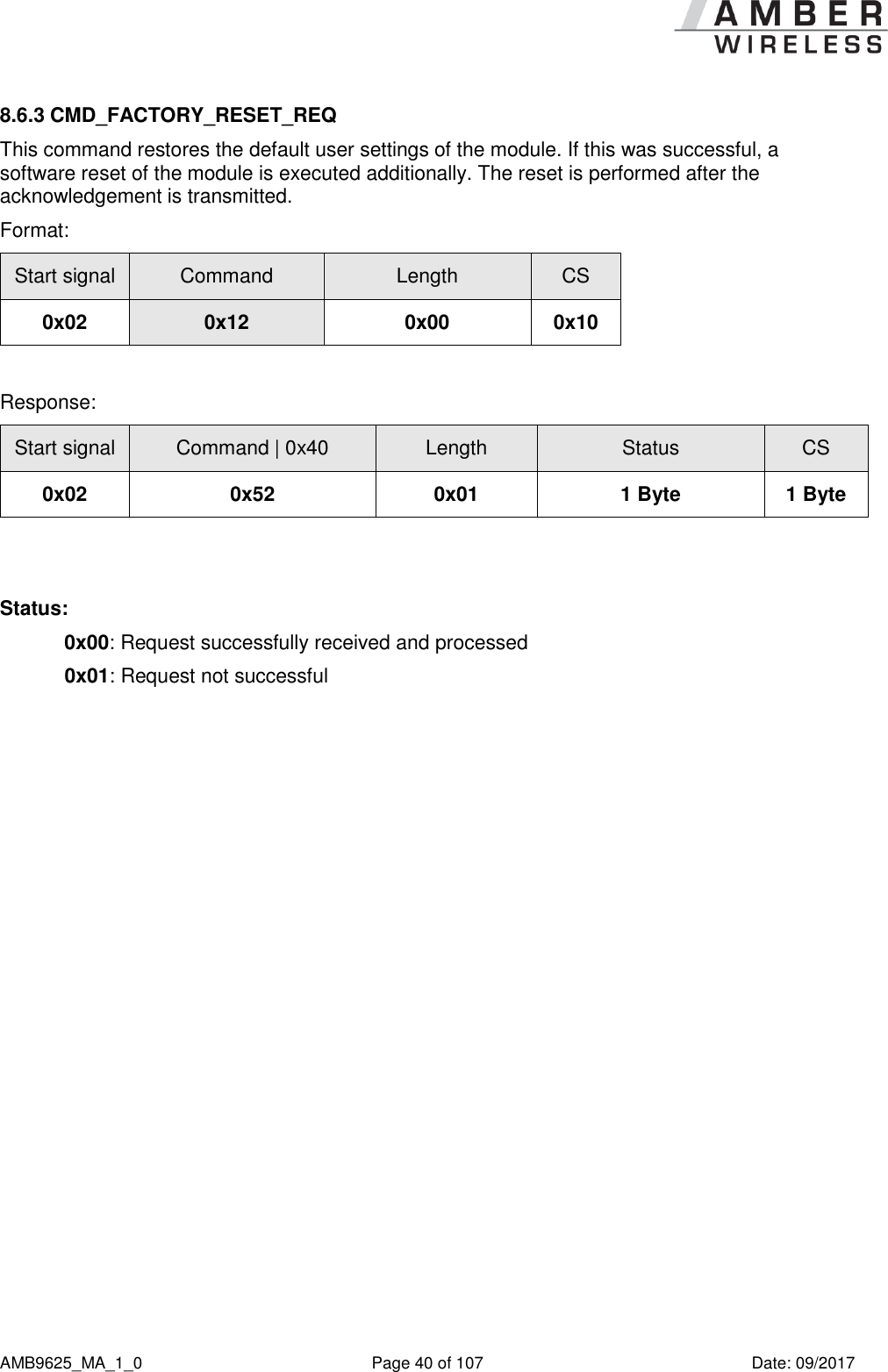
![AMB9625_MA_1_0 Page 64 of 107 Date: 09/2017 9.2.15 MAC_ACKTimeout Designation Summary Permissible values Default value Memory position Length MAC_ACKTimeout ACK timeout Waiting time for wireless acknowledgement [ms] 5 – 65535 10 32 2 Time to wait for a RF acknowledgement before a RF retry is triggered. RF data rate ACK timeout recommended 2.4 kbps 45 ms 38.4 kbps 8 ms 100.0 kbps 5 ms Table 6 Recommended timeouts 9.2.15.1 Example 1: Set the parameter MAC_ACKTimeout to 15. Command: Start signal Command Length + 2 Memory Position Length Parameter CS 0x02 0x09 0x04 0x20 0x02 0x0F 0x00 0x22 Response: Start signal Command | 0x40 Length Status CS 0x02 0x49 0x01 0x00 0x4A Request successfully received and processed. 9.2.15.2 Example 2: Read the MAC_ACKTimeout from memory position 32 and length 2. Command: Start signal Command Length Memory Position Amount of Bytes CS 0x02 0x0A 0x02 0x20 0x02 0x28 Response:](https://usermanual.wiki/Wuerth-Elektronik-eiSos-and-Co-KG/AMB9625/User-Guide-3598987-Page-64.png)

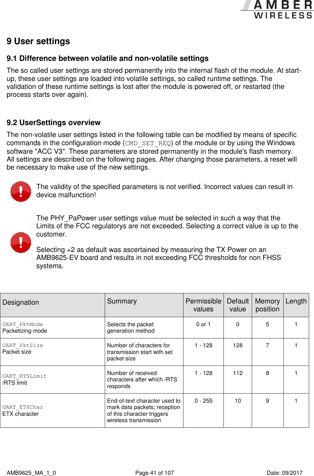
![AMB9625_MA_1_0 Page 66 of 107 Date: 09/2017 9.2.16 PHY_PAPower Designation Summary Permissible values Default value Memory position Length PHY_PAPower PA power Output power [dBm]; value range depends on RF configuration complement on two -11 …15 2 41 1 Parameter for the RF output power of the module. The value +2dBm was used so that the AMB9625-EV board is not exceeding the FCC limits. Other Boards, Platforms or Antennas may need to use reduced settings to achieve FCC compliance. The RF chip only supports discrete values. Mapping to the next possible PHY_PAPower value is done by the module. The next smaller PHY_PAPower value is always chosen when the transferred value is not possible. The step distance equals 1 dB. The usersettings PHY_PAPower is entered as a complement on two. Caution: The statutory regulations for the maximum power output have to be adhered to. 9.2.16.1 Example 1: Using the permissible value 0 dBm with parameter PHY_PAPower. Command: Start signal Command Length + 2 Memory Position Length Parameter CS 0x02 0x09 0x03 0x29 0x01 0x00 0x20 Response: Start signal Command | 0x40 Length Status CS 0x02 0x49 0x01 0x00 0x4A Request successfully received and processed 9.2.16.2 Example 2: Read the PHY_PAPower from memory position 41 and length 1. Command:](https://usermanual.wiki/Wuerth-Elektronik-eiSos-and-Co-KG/AMB9625/User-Guide-3598987-Page-66.png)
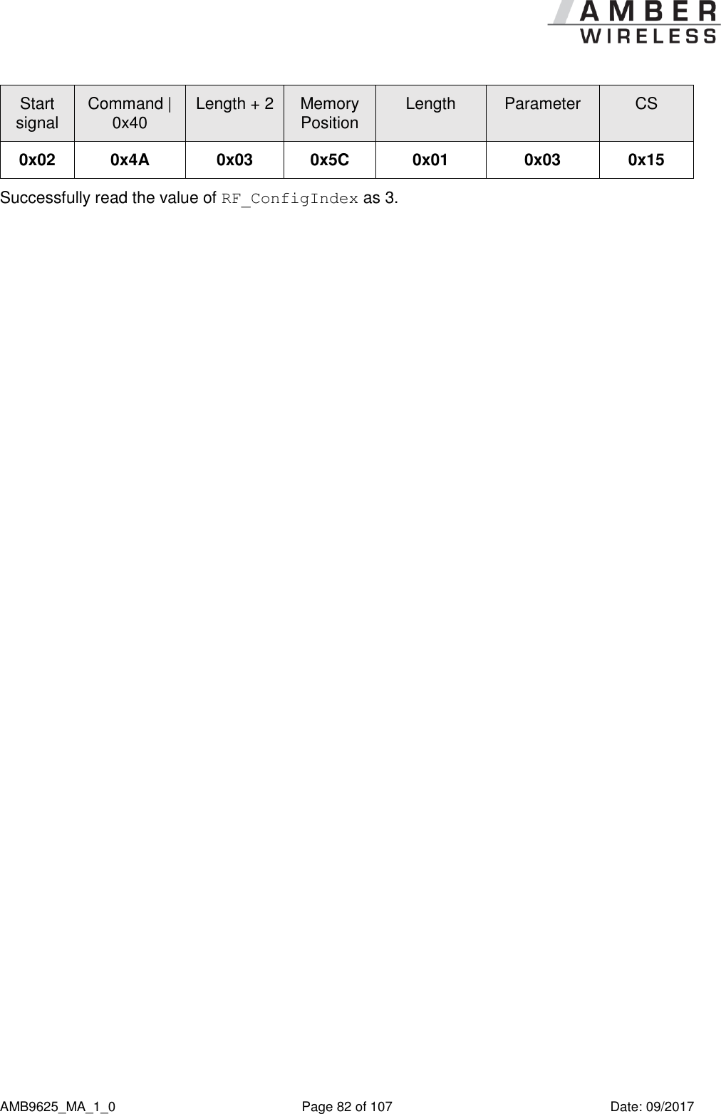
![AMB9625_MA_1_0 Page 81 of 107 Date: 09/2017 9.2.27 RF_ConfigIndex Designation Summary Permissible values Default value Memory position Length RF_ConfigIndex Configuration index 3 and 4 3 92 1 An 8 bit field that addresses the applied RF configuration. RF_ConfigIndex Data rate (gross) [kcps] Freq. range [kHz] Modulation Max packet time for repeater mode [ms] 3 38.4 20 GFSK 40 4 100 47 GFSK 20 Table 10 RF profiles 9.2.27.1 Example 1: Set the RF_ConfigIndex to 4. Command: Start signal Command Length + 2 Memory Position Length Parameter CS 0x02 0x09 0x03 0x5C 0x01 0x04 0x51 Response: Start signal Command | 0x40 Length Status CS 0x02 0x49 0x01 0x00 0x4A Request successfully received and processed 9.2.27.2 Example 2: Read the RF_ConfigIndex from memory position 92 and length 1. Command: Start signal Command Length Memory Position Amount of Bytes CS 0x02 0x0A 0x02 0x5C 0x01 0x57 Response:](https://usermanual.wiki/Wuerth-Elektronik-eiSos-and-Co-KG/AMB9625/User-Guide-3598987-Page-81.png)
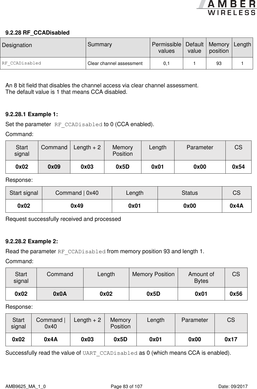
![AMB9625_MA_1_0 Page 84 of 107 Date: 09/2017 9.2.29 RF_CCACheckTime Designation Summary Permissible values Default value Memory position Length RF_CCACheckTime LSB (Index 95) und MSB(Index 96) Observation time [ms] 0-60000 5 94 2 A 16 bit field that contains the time in milliseconds for which the channel with activated CCA has to be observed and identified as free before channel access can take place. If CCA is used to implement LBT, to be not effected by the duty cycle requirements, the parameters have to be chosen in accordance with EN 300 220, and for systems with sporadic bursts of small data packets in accordance with EN 301 391. 9.2.29.1 Example 1: Set the RF_CCACheckTime to 10ms. Command: Start signal Command Length + 2 Memory Position Length Parameter CS 0x02 0x09 0x04 0x5E 0x02 0x0A 0x00 0x59 Response: Start signal Command | 0x40 Length Status CS 0x02 0x49 0x01 0x00 0x4A Request successfully received and processed. 9.2.29.2 Example 2: Read the RF_CCACheckTime from memory position 94 and length 2. Command: Start signal Command Length Memory Position Amount of Bytes CS 0x02 0x0A 0x02 0x5E 0x02 0x56 Response: Start signal Command | 0x40 Length + 2 Memory Position Length Parameter CS 0x02 0x4A 0x04 0x5E 0x02 0x05 0x00 0x15 Successfully read the value of RF_CCACheckTime as 5 ms.](https://usermanual.wiki/Wuerth-Elektronik-eiSos-and-Co-KG/AMB9625/User-Guide-3598987-Page-84.png)
![AMB9625_MA_1_0 Page 97 of 107 Date: 09/2017 17 Hardware integration 17.1 Footprint Figure 4 Footprint AMB9625 (also applicable for AMB8426), [mm] To avoid the risk of short circuits between VCC and GND, a minimum clearance of at least 14 mm between the opposing pad rows has to be maintained!](https://usermanual.wiki/Wuerth-Elektronik-eiSos-and-Co-KG/AMB9625/User-Guide-3598987-Page-97.png)
![AMB9625_MA_1_0 Page 103 of 107 Date: 09/2017 20 References [1] „CC1125 Single-Chip Low Cost Low Power RF-Transceiver”, Texas Instruments [2] „AMB9625 Datasheet”, AMBER wireless GmbH](https://usermanual.wiki/Wuerth-Elektronik-eiSos-and-Co-KG/AMB9625/User-Guide-3598987-Page-103.png)