Wuerth Elektronik eiSos and Co KG AMB9625 AMB9625 User Manual
AMBER Wireless GmbH AMB9625 Users Manual
Users Manual


AMB9625_MA_1_0 Page 2 of 107 Date: 09/2017
Table of Contents
1 Summary ................................................................................................................................ 6
2 Electrical parameters ............................................................................................................ 7
2.1 Input voltage ..................................................................................................................... 7
2.2 Power consumption .......................................................................................................... 7
3 Dimensions and weight ........................................................................................................ 7
4 Pinout ..................................................................................................................................... 8
5 Start-up and minimal configuration ................................................................................... 10
5.1 Minimal configuration ...................................................................................................... 10
5.2 Sending & Receiving: “Hello World” in transparent mode ................................................ 10
5.3 Sending & Receiving: “Hello World” in command mode .................................................. 11
5.4 Adopting parameters to fit your application ..................................................................... 13
5.5 Deployment of several modules, use of addresses ......................................................... 13
6 Host connection: Serial interface ....................................................................................... 14
6.1 UART .............................................................................................................................. 14
6.1.1 Supported data rates and data formats..................................................................... 14
6.2 SPI interface ................................................................................................................... 14
7 Modes ................................................................................................................................... 15
7.1 Operating modes ............................................................................................................ 15
7.1.1 Switching from transparent to command mode ......................................................... 15
7.1.2 Switching from command to transparent mode ......................................................... 15
7.1.3 Transparent mode .................................................................................................... 16
7.1.4 Command mode ....................................................................................................... 16
8 The command interface ...................................................................................................... 17
8.1 Overview ......................................................................................................................... 17
8.2 Message overview .......................................................................................................... 18
8.3 Data transfer & reception in the command mode ............................................................ 20
8.3.1 CMD_DATA_REQ .................................................................................................... 20
8.3.2 CMD_DATAEX_REQ ............................................................................................... 21
8.3.3 CMD_DATAEX_IND ................................................................................................. 23
8.3.4 CMD_DATARETRY_REQ ........................................................................................ 24
8.3.5 CMD_REPEAT_IND ................................................................................................. 25
8.4 Requesting parameters and actions ................................................................................ 26
8.4.1 CMD_FWRELEASE_REQ ........................................................................................ 26
8.4.2 CMD_SERIALNO_REQ ........................................................................................... 27
8.4.3 CMD_RESET_REQ .................................................................................................. 28
8.4.4 CMD_RSSI_REQ ..................................................................................................... 28
8.4.5 CMD_ERRORFLAGS_REQ ..................................................................................... 30
8.5 Modification of volatile parameters .................................................................................. 31
8.5.1 CMD_SET_MODE_REQ .......................................................................................... 31
8.5.2 CMD_SET_PAPOWER_REQ .................................................................................. 33
8.5.3 CMD_SET_CHANNEL_REQ .................................................................................... 34
8.5.4 CMD_SET_DESTNETID_REQ ................................................................................ 35
8.5.5 CMD_SET_DESTADDR_REQ ................................................................................. 36
8.6 Modification of non-volatile parameters ........................................................................... 37
8.6.1 CMD_SET_REQ ...................................................................................................... 37
8.6.2 CMD_GET_REQ ...................................................................................................... 39
8.6.3 CMD_FACTORY_RESET_REQ ............................................................................... 40

AMB9625_MA_1_0 Page 3 of 107 Date: 09/2017
9 User settings........................................................................................................................ 41
9.1 Difference between volatile and non-volatile settings ...................................................... 41
9.2 UserSettings overview .................................................................................................... 41
9.2.1 UART_PktMode ....................................................................................................... 43
9.2.2 UART_PktSize ......................................................................................................... 46
9.2.3 UART_RTSLimit ....................................................................................................... 47
9.2.4 UART_ETXChar ....................................................................................................... 48
9.2.5 UART_Timeout ......................................................................................................... 50
9.2.6 UART_DIDelay ......................................................................................................... 52
9.2.7 MAC_NumRetrys ..................................................................................................... 54
9.2.8 MAC_AddrMode ....................................................................................................... 56
9.2.9 MAC_NumRetrysCCA .............................................................................................. 58
9.2.10 MAC_CCARetryDelay ............................................................................................ 59
9.2.11 MAC_DefaultDestNetID .......................................................................................... 60
9.2.12 MAC_DefaultDestAddrLSB ..................................................................................... 61
9.2.13 MAC_DefaultSourceNetID ...................................................................................... 62
9.2.14 MAC_DefaultSourceAddrLSB ................................................................................. 63
9.2.15 MAC_ACKTimeout ................................................................................................. 64
9.2.16 PHY_PAPower ....................................................................................................... 66
9.2.17 PHY_DefaultChannel ............................................................................................. 67
9.2.18 PHY_CCAThr ......................................................................................................... 68
9.2.19 OpMode ................................................................................................................. 69
9.2.20 CfgFlags ................................................................................................................. 70
9.2.21 RpFlags .................................................................................................................. 73
9.2.22 RP_NumSlots ......................................................................................................... 75
9.2.23 UART_Baudrate ..................................................................................................... 77
9.2.24 UART_Databits ...................................................................................................... 78
9.2.25 UART_Parity .......................................................................................................... 79
9.2.26 UART_Stoppbits ..................................................................................................... 80
9.2.27 RF_ConfigIndex ..................................................................................................... 81
9.2.28 RF_CCADisabled ................................................................................................... 83
9.2.29 RF_CCACheckTime ............................................................................................... 84
10 Device addressing and wireless monitoring ................................................................... 85
11 Radio parameters .............................................................................................................. 86
11.1 Channel assignment ..................................................................................................... 87
12 Using the repeater functionality ....................................................................................... 88
12.1.1 Setup of the network and repeater device .............................................................. 89
12.1.2 Example network .................................................................................................... 90
12.1.3 Application in parallel networks............................................................................... 91
13 Battery powered operation ............................................................................................... 92
13.1 Active mode .................................................................................................................. 92
13.2 Stand-by mode ............................................................................................................. 92
14 Timing parameters ............................................................................................................ 93
14.1 Reset behaviour ............................................................................................................ 93
14.1.1 Power-on reset ....................................................................................................... 93
14.1.2 Reset via /RESET pin ............................................................................................. 93
14.1.3 Reset as result of a serious error condition ............................................................. 93
14.2 Latencies when leaving the LPM ................................................................................... 93
14.3 Latencies during data transfer / packet generation ........................................................ 93
15 Firmware update ................................................................................................................ 95

AMB9625_MA_1_0 Page 4 of 107 Date: 09/2017
15.1 Update using UART interface ........................................................................................ 95
15.2 Update using JTAG or Spy-Bi-Wire ............................................................................... 95
16 Firmware history ............................................................................................................... 96
17 Hardware integration ......................................................................................................... 97
17.1 Footprint ....................................................................................................................... 97
18 Design in guide .................................................................................................................. 98
18.1 Advice for schematic and layout .................................................................................... 98
18.2 Dimensioning of the 50 Ohm microstrip ...................................................................... 100
18.3 Antenna solutions ....................................................................................................... 100
18.3.1 Lambda/4 radiator ................................................................................................ 101
18.3.2 Chip antenna ........................................................................................................ 101
18.3.3 PCB antenna ........................................................................................................ 101
19 Manufacturing information ............................................................................................. 102
20 References ....................................................................................................................... 103
21 Regulatory compliance information ............................................................................... 104
21.1 Important notice .......................................................................................................... 104
21.2 FCC Compliance statement AMB9625 ........................................................................ 105
21.3 IC Compliance statement AMB9625 ........................................................................... 105
21.4 FCC and IC Requirements to OEM integrators ........................................................... 105
22 Important information ..................................................................................................... 107
22.1 Exclusion of liability ..................................................................................................... 107
22.2 Trademarks ................................................................................................................. 107
22.3 Usage restriction ......................................................................................................... 107

AMB9625_MA_1_0 Page 5 of 107 Date: 09/2017
Abbreviations and abstract
ACK
Acknowledgement
Acknowlegdement pattern confirming the reception of the
transmitted data package
CS
Checksum
DC
Duty cycle
Relative frequency reservation period
LPM
Low power mode
Operation mode for efficient power consumption.
RF
Radio frequency
Describes everything relating to the wireless transmission
Payload
The real, non-redundant information in a frame/packet
User
settings
Any relation to a specific entry in the user settings is marked
in a special font and can be found in the respective chapter
UART
Universal Asynchronous Receiver Transmitter, allows to
communicate with the module of a specific interface.
Duty cycle
Transmission time in relation of one hour
1% means, channel is occupied for 36 seconds per hour.
Hexadecimal
[HEX]
0xhh
All numbers beginning with 0x are stated as hexadecimal
numbers. All other numbers are decimal.

AMB9625_MA_1_0 Page 6 of 107 Date: 09/2017
1 Summary
The AMB9625 module was designed as a radio sub module for wireless communication
between devices such as control systems, remote controls, sensors etc. It offers several
addressing modes and relieves the host system of radio-specific tasks such as
checksum calculation,
address resolution, and
repetition of unacknowledged telegrams.
It can be deployed wherever the wireless exchange of small data packets (up to 128 bytes)
between two or more parties is required.
A serial interface (UART) whose data rate and format can be adjusted flexibly is available for
communicating with the host system.
The AMB9625 is fully pin-compatible with the AMB8626 (for 868 MHz Band) and AMB9626
(FHSS for 915MHz Band).
The following chapters give a short description of settings, which can be configured in the non-
volatile user settings, detailed description in chapter 8.
AMB9625_MA_1_0 Page 7 of 107 Date: 09/2017
2 Electrical parameters
2.1 Input voltage
Description
min
typ
max
unit
Supply voltage
2.0
2.5
3.6
V
2.2 Power consumption
Description
typ
unit
TX current consumption
(@PHY_PaPower=0x0D)
58
mA
TX current consumption
(@PHY_PaPower=0x02)
30
mA
RX current consumption
30
mA
Low Power
3
µA
3 Dimensions and weight
Dimensions
17 x 27 mm
Weight
3 g
AMB9625_MA_1_0 Page 8 of 107 Date: 09/2017
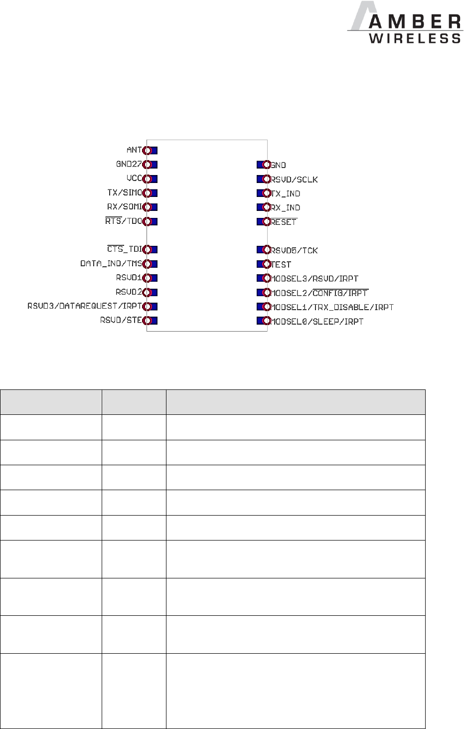
4 Pinout
Figure 1 Pinout
Designation
I/O
Description
ANT
I/O
Antenna connection
VCC
Supply
Supply voltage
GND, GND27
Supply
Ground
TX
Output
UART(Transmission)
RX
Input
UART (Reception)
/RESET
Input
Active low. Internally network to VCC.
Do not connect if not needed.
/CONFIG
Input
Switch the module to command mode, falling edge.
Connect to GND if not needed.
SLEEP
Input
Reserved.
Connect to GND
TRX_DISABLE
Input
Switches the RF (RX) part off, high level, as long as
no data is to be sent. The pin level must be set to
GND during boot up. The boot up finished when
/RTS is low.
Connect to GND if not needed.

AMB9625_MA_1_0 Page 9 of 107 Date: 09/2017
Designation
I/O
Description
/DATA_REQUEST
Input
Prompts the wireless transmission, falling edge. As
long as no new data is received via UART or
wireless transmission, the buffer content remains
valid and can be resent by means of a new signal.
If the function of this pin is enabled (see 9.2.20),
this pin has an internal pull-up resistor. If the pin
function is disabled and the pin is not needed,
connect it to the GND.
Without function in the command mode.
/RTS
Output
Ready to send, active low.
Signalizes a busy UART buffer. When Set, no more
bytes will be accepted over UART.
/CTS
Input
Clear To Send, active low. Can be used to signalize
to the AMB9625 that the connected host’s buffer is
busy.
/DATA_INDICATE
Output
Packet received, active low. Goes low as soon as a
valid packet with correct address is received via
radio and remains low as long as the output via
UART continues. Can be used to prepare a
"sleeping" host system for the output of data.
The delay between the falling edge and the start of
transmission via UART can be configured with
UART_DIDelay.
TX_INDICATE /
RX_INDICATE
Output
Shows radio activity, active high.
RESERVED
Reserved for currently not implemented functions
e.g. SPI.
Do not connect.
TEST
JTAG
For JTAG / SPY-Bi-Wire. Do not connect.
Table 1 Pinout
AMB9625_MA_1_0 Page 10 of 107 Date: 09/2017
5 Start-up and minimal configuration
5.1 Minimal configuration
In the factory state, the modules are immediately ready for operation; the following pins are
required in the minimal configuration: VCC, GND, UTXD, and URXD.
If the module has to be connected to a PC, an adaptor (TTL to RS-232 or TTL to USB) has to
be used. The AMB9625-EV is suited for this.
In the default configuration all module inputs (TRX_DISABLE and /CONFIG) are activated and
must be connected as shown in Table 1. If the function of the /DATA_REQUEST pin is enabled
(see chapter 9.2.20), this pin has an internal pull-up resistor.
If TRX_DISABLE is used by the host it must be set to GND during start-up / after
reset till the module’s start-up is completed. The module will wait for this pin to go to
GND level before finishing its start-up procedure. The module’s UART or function
pins (such as /CONFIG) will not be available until the start-up is finished.
5.2 Sending & Receiving: “Hello World” in transparent mode
In factory state the module is in transparent mode.
Connect your pair of modules, EV-boards or USB-sticks with the PC as explained in chapter
5.1. Please make sure you have a minimum distance of 3 meters between the two modules or
devices to avoid overmodulation. When short distances are needed, you could reduce the
RF_PAPower to a minimum.
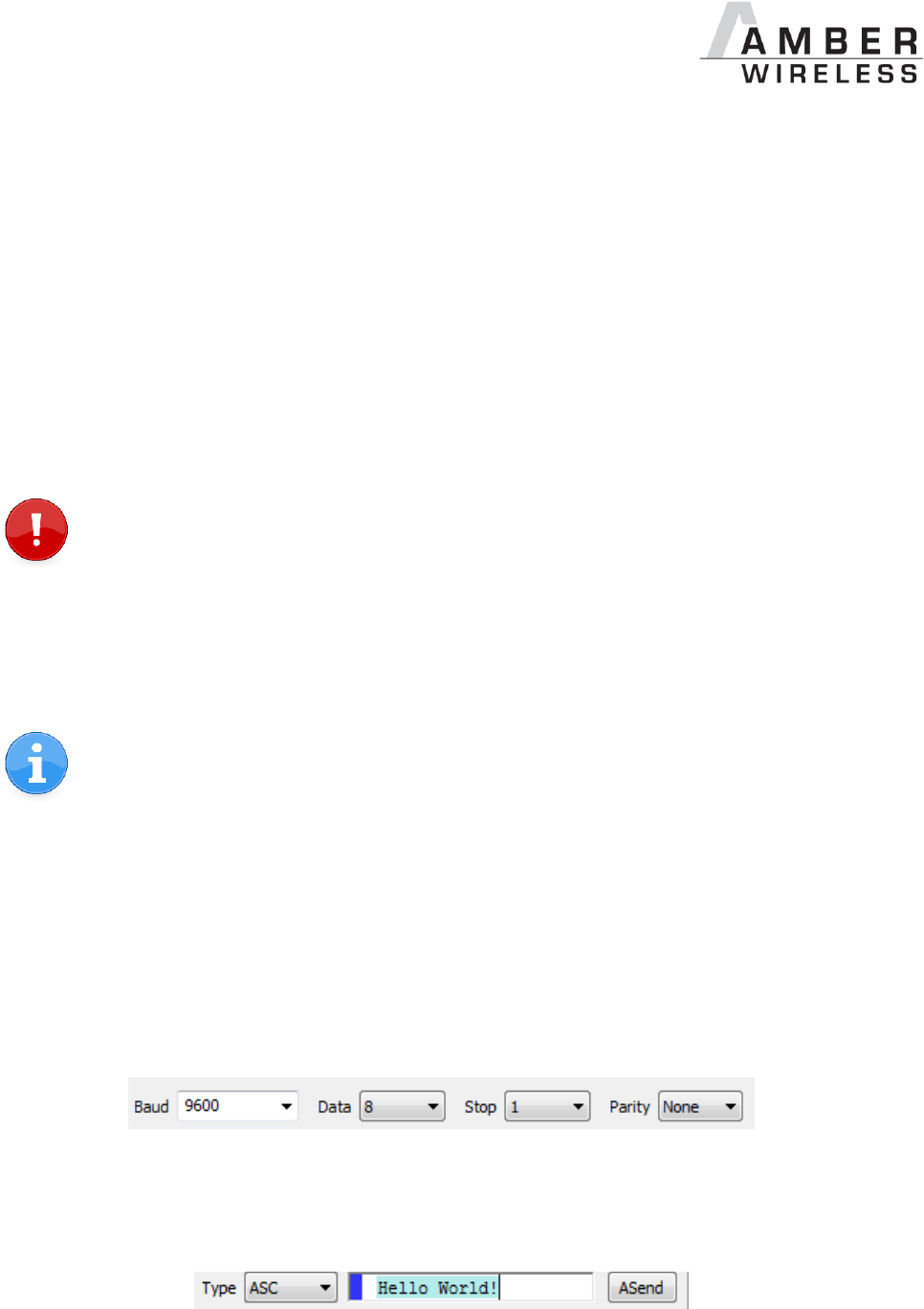
When the connection to the PC is done, please use a terminal tool of your choice. For
convenience we assume you selected the tool “hterm”. Select the two corresponding COM ports
and open them with a configuration of 9600 Baud, 8 Data bits, 1 Stop bit and Parity set to None.
Enter the string “Hello World” into the input line of hterm and use the “ASend” button followed by
pushing the “start” button to send the data once.
AMB9625_MA_1_0 Page 11 of 107 Date: 09/2017
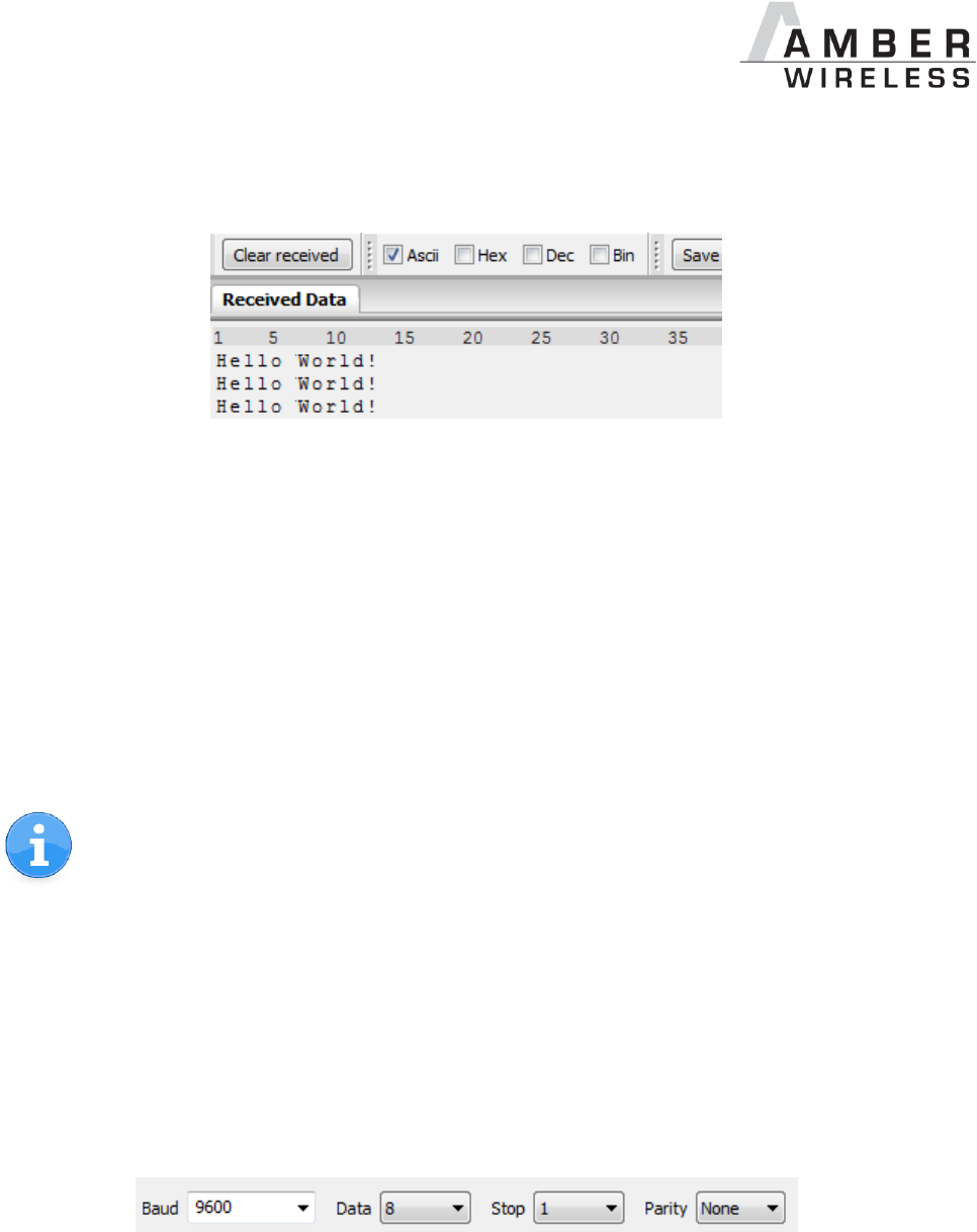
This data will be received by the second module and shows up as received data in the second
hterm instance. You may send any string of size 1 to 128 characters from one module to the
other.
You just used the so called “transparent mode” of the modules to send your data. The address
mode that was used is “0”. Thus all radio frames are broadcasts that can be received by anyone
listening with an AMB9625 in default settings. The frame you send was generated using the
timeout method.
Besides the transparent mode, that is suited for transparent data transmission, the so called
“command mode” allows both, the module configuration and the data transmission, using a
predefined command interface (see chapter 8).
5.3 Sending & Receiving: “Hello World” in command mode
Be sure that the module runs in command mode by default.
Connect your pair of modules, EV-boards or USB-sticks with the PC as explained in chapter
5.1. Please make sure you have a minimum distance of 3 meters between the two modules or
devices to avoid over modulation. When short distances are needed, you could reduce the
RF_PAPower to a minimum.
A terminal program, for example hterm, is used to perform the communication over the COM
ports. The two corresponding COM ports have to be selected and opened with a configuration
of 9600 baud, 8 Data bits, 1 Stop bit and Parity set to none.
As soon as the module is ready for operation (at start-up or after a reset) a CMD_RESET_IND
message (0x02 0x45 0x01 0x00 0x46) is sent on the UART. Eventually the reset button has to
be pushed (or CMD_RESET_REQ performed) to see this message.
AMB9625_MA_1_0 Page 12 of 107 Date: 09/2017
If the CMD_RESET_IND message did not occur after resetting, the module is not in
command mode.
In factory state the default address mode is “0”, which means that all radio frames are
broadcasts that can be received by anyone listening with an AMB9625 in default settings.
Transmitter
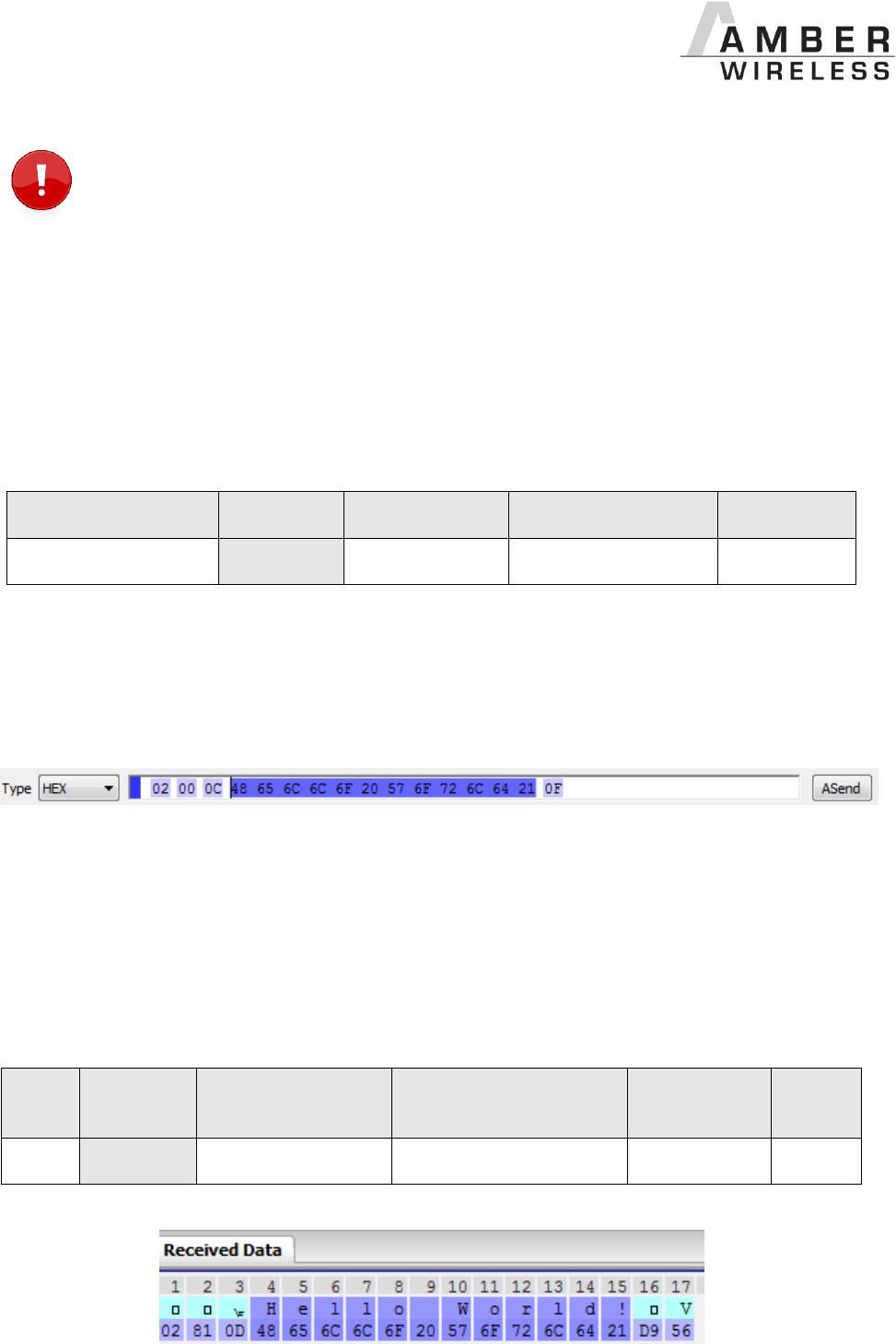
To send the string “Hello World”, the corresponding CMD_DATA_REQ has to be inserted into the
input line of hterm. The command CMD_DATA_REQ has the following structure:
Start signal
Command
Payload Length
Payload
CS
0x02
0x00
1 Byte
Payload length
1 Byte
In this case the payload has a length of 12 (0x0C) bytes and 0x48 0x65 0x6C 0x6C 0x6F 0x20
0x57 0x6F 0x72 0x6C 0x64 0x21 (Hello World!) is the payload data. The checksum CS is a
XOR conjunction of all previous bytes, which in this case is 0x0F.
Using the “ASend” button followed by pushing the “start” button sends the data once.
The sending module answers with a CMD_DATA_CNF to confirm that the request has been
received.
Receiver
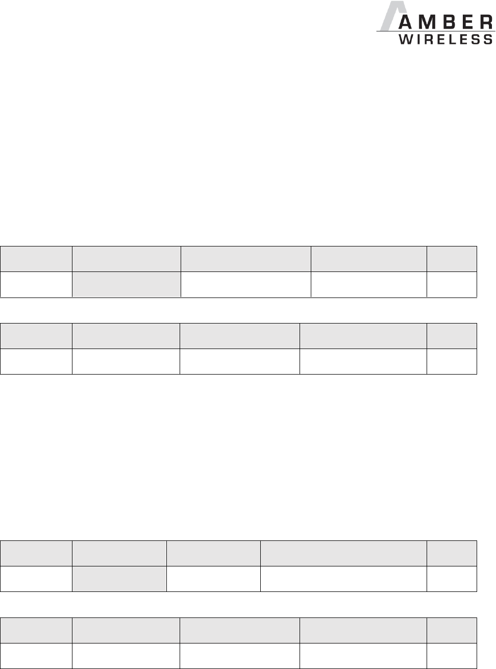
In factory state, the second module receiving this packet outputs a CMD_DATAEX_IND message
which format is as follows:
Start
signal
Command
Payload length + 1
Payload
RSSI
CS
0x02
0x81
1 Byte
Payload length
1 Byte
1 Byte

AMB9625_MA_1_0 Page 13 of 107 Date: 09/2017
Thus the CMD_DATAEX_IND message informs us that we received a packet with payload of
0x0D (13) bytes. 12 byte of these are user payload (0x48 0x65 0x6C 0x6C 0x6F 0x20 0x57
0x6F 0x72 0x6C 0x64 0x21 = Hello World!) and one byte is the RSSI value (here 0xD9, which is
two’s complement for -39 dBm) directly outputted behind the payload, before the checksum.
5.4 Adopting parameters to fit your application
The non-volatile parameters (see chapter 9) can only be changed in the command mode by
using the CMD_SET_REQ command. This command will need the following parameters:
memory position of the parameter
the new value that shall be applied to this parameter
Furthermore, there are volatile settings that can be accessed by explicit commands for each
parameter. All available commands are introduced in chapter 8.
5.5 Deployment of several modules, use of addresses
Settings like the module address can only be modified in the command mode. Thus we
recommend to permanently operate in command mode by setting the user settings parameter
OpMode to the value of 0x10 (16).
To use non-broadcast transmissions you need to adopt the following non-volatile settings:
MAC_AddrMode (mode 1 or 2 should be used depending on the number of addresses
you need)
MAC_DefaultSourceAddrLSB as the local address for each device of your network, each
member of the network will need an unique address. A value of 255 is invalid.
MAC_DefaultSourceNetID, as the local network address for each device of your
network, each member of the network will need an unique address. A value of 255 is
invalid.
In command mode, the command CMD_DATAEX_REQ, that has the destination address as an
own parameter, can be used to send your data to the specified address. A broadcast message
can still be achieved when using 0xFF (255) for both destination address LSB and destination
net ID.

AMB9625_MA_1_0 Page 14 of 107 Date: 09/2017
6 Host connection: Serial interface
6.1 UART
6.1.1 Supported data rates and data formats
The data rate is adjusted through a configuration structure. The structure allows the
configuration of the UART_Baudrate, UART_Databits, UART_Parity and
UART_Stoppbits.
Since the UART speed is derived from a digitally calibrated oscillator, this may result in
variations of up to ± 2 %.
The default baud rate of the AMB9625 is 9600 baud.
The output of characters on the serial interface takes place with secondary priority. For this
reason, short interruptions may occur between the output of individual characters (e.g. in the
event of an interrupt).
The following data formats are supported:
7 or 8 bits
None, even, or odd parity
1 or 2 stop bits
The default data format is 8 data bits, no parity and 1 stop bit ("8n1").
6.2 SPI interface
As an alternative to the UART interface a version with SPI interface can be implemented upon
requested (separate firmware).

AMB9625_MA_1_0 Page 15 of 107 Date: 09/2017
7 Modes
7.1 Operating modes
The AMB9626/AMB9665 can be used in the following operating modes:
1. Transparent mode (transparent data transmission)
2. Command mode (module configuration and data transmission using the predefined
command interface)
The operating mode after power-up can be configured by means of the OpMode parameter. By
default, the module operates in transparent mode.
Starting in the command mode, the module responds with a CMD_SET_MODE_CNF telegram.
7.1.1 Switching from transparent to command mode
The command mode can be entered by applying a falling edge on the /CONFIG pin. The
detection of the falling edge on the /CONFIG pin can be disabled using the user setting
CfgFlags.
The successful switchover is acknowledged by a CMD_SET_MODE_CNF (0x02 0x44 0x01 0x10
0x57) telegram indicating command mode.
The switchover can only occur when no data is being received by wireless transmission or
UART interface (approximately 100 µs after /RTS goes low and indicates readiness).
7.1.2 Switching from command to transparent mode
The transparent mode can be entered by applying a falling edge on the /CONFIG pin or by
using the command CMD_SET_MODE_REQ . The detection of the falling edge on the /CONFIG
pin can be disabled using the user setting CfgFlags.
The successful switchover is acknowledged by a CMD_SET_MODE_CNF (0x02 0x44 0x01 0x00
0x47) telegram indicating transparent mode.
The switchover can only occur when no data is being received by wireless transmission or
UART interface (approximately 100 µs after /RTS goes low and indicates readiness).
Recommendation: Automatic switching to a specific mode can be realized by
applying falling edges on the /CONFIG pin as long as the needed
CMD_SET_MODE_CNF is returned:
0x02 0x44 0x01 0x10 0x57 telegram indicating command mode
0x02 0x44 0x01 0x00 0x47 telegram indicating transparent mode

AMB9625_MA_1_0 Page 16 of 107 Date: 09/2017
7.1.3 Transparent mode
In this mode, data is received via the serial interface and initially buffered. As soon as a specific
condition is met, the RF telegram is generated with a preamble, checksum, and address
information (optional).
To initiate an RF transmission, several options are available, listed in Table 2.
Start Condition
Description:
Dependent usersettings
Timeout
Transmission starts if no new character is
detected within a configurable time period after
receiving a character via UART. The timeout is
reset every time a new character is received.
UART_Timeout
UART_PktMode
End-Of-Text-
Character
Transmission begins when the preconfigured
character is transmitted via UART.
UART_PktMode
UART_ETXChar
Fixed Packet Size
Transmission starts when the preconfigured
number of bytes is reached in the RX buffer of
the UART.
UART_PktSize
UART_RTSLimit
UART_PktMode
/Data Request Pin
The transmission starts as soon as a falling
edge is detected on the /DATA_REQUEST pin.
CfgFlags
Table 2 Communication in transparent mode
The UART_PktMode parameter (see 9.2.1) can be used to determine which of the listed
combinations is to be used.
7.1.3.1 /RTS signal, busy processor
/RTS signalizes a busy UART buffer which means, when /RTS is set, no more UART bytes will
be accepted nor processed.
/RTS is set when any of the events in the prior chapter has occurred.
7.1.4 Command mode
This operating mode primarily serves module configuration. The module AMB9625 acts as a
slave and can be fully controlled by an external host using the commands of the command
interface (see chapter 9.2.29.1).
It can also be used for wireless transmission of payload data providing a feedback dependent
on the transmission success.

AMB9625_MA_1_0 Page 17 of 107 Date: 09/2017
8 The command interface
8.1 Overview
In the command mode, communication with the module occurs in form of predefined
commands. These commands must be sent in telegrams according to the format described in
Table 3.
Start signal
Command
No. of data
Data
Checksum
Table 3 Telegram format in the command mode
Start signal: 0x02 (1 byte)
Command: One of the predefined commands according to chapter 9.2.29.1 (1 byte)
No. of data: Specifies the number of data in the following field of variable length and is limited
to 128 in order to prevent buffer overflow (1 byte). With appropriate commandos
values > 128 can occur.
Data: Variable number of data or parameters (maximum 128 byte, payload plus 6 byte
parameter, LSB first)
Checksum: Byte wise XOR combination of the preceding fields including the start signal,
i.e. 0x02 ^ command ^ no. of data ^ data byte 0 ... (1 byte)
Using a specific command, data can also be sent via RF, i.e. the module can be operated
entirely in the command mode. Only in this way quick channel changes, can be realized.
If no new signal is received for UART_Timeout milliseconds after receiving the STX signal, the
unit will wait for a new start signal.
On each command follows a response from the AMB9625 to the host.

AMB9625_MA_1_0 Page 18 of 107 Date: 09/2017
8.2 Message overview
Start
signal
CMD
Message name
Short description
Chapter
Requests
0x02
0x00
CMD_DATA_REQ
Send data to configured address
8.3.1
0x02
0x01
CMD_DATAEX_REQ
Send data to specific address
8.3.2
0x02
0x02
CMD_DATARETRY_REQ
Resend the transmission of the
data submitted earlier
8.3.4
0x02
0x04
CMD_SET_MODE_REQ
Change into new operating mode
8.5.1
0x02
0x05
CMD_RESET_REQ
Reset module
8.4.3
0x02
0x06
CMD_SET_CHANNEL_REQ
Change the RF channel
8.5.3
0x02
0x07
CMD_SET_DESTNETID_REQ
Set the destination network ID
8.5.4
0x02
0x08
CMD_SET_DESTADDR_REQ
Set the destination address
8.5.5
0x02
0x09
CMD_SET_REQ
Change the user settings
8.6.1
0x02
0x0A
CMD_GET_REQ
Read the user settings
8.6.2
0x02
0x0B
CMD_SERIALNO_REQ
Request the individual serial
number of the module
8.4.2
0x02
0x0C
CMD_FWRELEASE_REQ
Request the firmware version of
the module
8.4.1
0x02
0x0D
CMD_RSSI_REQ
Request RSSI of last packet
8.4.4
0x02
0x0E
CMD_ERRORFLAGS_REQ
Returns internal error states
8.4.4
0x02
0x11
CMD_SET_PAPOWER_REQ
Change the RF TX power
8.5.2
0x02
0x12
CMD_FACTORY_RESET_REQ
Perform a factory reset
8.6.3
Confirmations
0x02
0x40
CMD_DATA_CNF
Data has been sent
8.3.1
8.3.2
0x02
0x41
Reserved
0x02
0x42
CMD_DATARETRY_CNF
Data has been resent
8.3.4
0x02
0x44
CMD_SET_MODE_CNF
Operating mode has been
changed
8.5.1
0x02
0x45
CMD_RESET_CNF
Reset request received
8.4.3
0x02
0x46
CMD_SET_CHANNEL_CNF
Channel has been updated
8.5.3

AMB9625_MA_1_0 Page 19 of 107 Date: 09/2017
0x02
0x47
CMD_SET_DESTNETID_CNF
Destination network ID has been
updated
8.5.4
0x02
0x48
CMD_SET_DESTADDR_CNF
Destination address has been
updated
8.5.5
0x02
0x49
CMD_SET_CNF
User settings have been updated
8.6.1
0x02
0x4A
CMD_GET_CNF
Return the requested user setting
values
8.6.2
0x02
0x4B
CMD_SERIALNO_CNF
Serial number request received
8.4.2
0x02
0x4C
CMD_FWRELEASE_CNF
Firmware version request
received
8.4.1
0x02
0x4D
CMD_RSSI_CNF
RSSI request received
8.4.4
0x02
0x4E
CMD_ERRORFLAGS_CNF
Internal error states have been
returned
8.4.4
0x02
0x51
CMD_SET_PAPOWER_CNF
RF TX power has been changed
8.5.2
0x02
0x52
CMD_FACTORY_RESET_CNF
Factory reset request received
8.6.3
Indications
0x02
0x80
CMD_REPEAT_IND
Data has been repeated
8.3.5
0x02
0x81
CMD_DATAEX_IND
Data has been received
8.3.3
Table 4 Message overview
AMB9625_MA_1_0 Page 20 of 107 Date: 09/2017
8.3 Data transfer & reception in the command mode
This group of commands includes the commands that are used to either request a radio
telegram to be send or indicates a received frame.
8.3.1 CMD_DATA_REQ
This command serves the simple data transfer in the command mode. Transmission takes place
on the configured channel to the previously parameterised destination address.
This command is especially suitable for transmission for a point-to-point connection. The
number of payload data bytes is limited to 128.
Format:
Start signal
Command
Payload length
Payload
CS
0x02
0x00
1 Byte
Payload length
1 Byte
Response:
Start signal
Command | 0x40
Length
Status
CS
0x02
0x40
0x01
1 Byte
1 Byte
Status:
0x00: ACK received or not requested (MAC_NumRetrys is 0 or MAC_AddrMode is 0)
0x01: no ACK received
8.3.1.1 Example 1:
Transmit “Hello” (0x48 0x65 0x6C 0x6C 0x6F).
Command:
Start signal
Command
Payload length
Payload
CS
0x02
0x00
0x05
0x48 0x65 0x6C 0x6C 0x6F
0x45
Response:
Start signal
Command | 0x40
Length
Status
CS
0x02
0x40
0x01
0x00
0x43
Transmission of “Hello” was successful

AMB9625_MA_1_0 Page 21 of 107 Date: 09/2017
8.3.2 CMD_DATAEX_REQ
This command serves data transfer in a network with several parties. Both the channel to use
and the destination address (depending on the parameterised addressing mode) are specified
along with the command. The number of payload data bytes is limited to 128. The entered
channel, destination network and destination address are loaded into the volatile runtime
settings und thus kept until the system is reset.
Format in addressing mode 0:
Start
signal
Command
Payload length + 1
Channel
Payload
CS
0x02
0x01
1 Byte
1 Byte
Payload length
1 Byte
Format in addressing mode 1:
Start
signal
Command
Payload length + 2
Channel
Destination
address
Payload
CS
0x02
0x01
1 Byte
1 Byte
1 Byte
Payload length
1 Byte
Format in addressing mode 2:
Start
signal
Command
Payload
length + 3
Channel
Destination
network ID
Destination
address
Payload
CS
0x02
0x01
1 Byte
1 Byte
1 Byte
1 Byte
Payload
length
1
Byte
Response:
Start signal
CMD_DATA_REQ
| 0x40
Length
Status
CS
0x02
0x40
0x01
1 Byte
1 Byte
Status:
0x00: ACK received or not requested (MAC_NumRetrys is 0 or MAC_AddrMode is 0)
0x01: no ACK received
0x02: invalid channel selected
8.3.2.1 Example 1:
Transmit “Goodbye” in addressing mode 1 on channel 108 (0x6A) to address 5
Command:

AMB9625_MA_1_0 Page 22 of 107 Date: 09/2017
Start
signal
Command
Payload
length + 2
Channel
Destination
address
Payload
CS
0x02
0x01
0x09
0x6A
0x05
0x47 0x6F 0x6F 0x64
0x62 0x79 0x65
0x38
Response:
Start signal
CMD_DATA_REQ
| 0x40
Length
Status
CS
0x02
0x40
0x01
0x00
0x43
“Goodbye” was successfully transmitted

AMB9625_MA_1_0 Page 23 of 107 Date: 09/2017
8.3.3 CMD_DATAEX_IND
This telegram indicates the reception of data bytes and represents the counterpart to the
commands CMD_DATA_REQ and CMD_DATAEX_REQ. Apart from the RX field strength (RSSI
value), this telegram also specifies the sender address (depending on the parameterised
addressing mode).
Format in addressing mode 0:
Start
signal
Command
Payload length + 1
Payload
RSSI
CS
0x02
0x81
1 Byte
Payload length
1 Byte
1 Byte
Format in addressing mode 1:
Start
signal
Command
Payload
length + 2
Sender
address
Payload
RSSI
CS
0x02
0x81
1 Byte
1 Byte
Payload length
1 Byte
1
Byte
Format in addressing mode 2:
Start
signal
Command
Payload
length + 3
Sender
network ID
Sender
address
Payload
RSSI
CS
0x02
0x81
1 Byte
1 Byte
1 Byte
Payload
length
1 Byte
1
Byte
8.3.3.1 Example 1:
Data was received in MAC_DefaultAddressMode 0:
The CMD_DATAEX_IND message informs us that we received a packet with payload of 0x0D
(13) bytes. 12 byte of these are user payload (0x48 0x65 0x6C 0x6C 0x6F 0x20 0x57 0x6F
0x72 0x6C 0x64 0x21 = Hello World!) and one byte is the RSSI value (here 0xD9, which is two’s
complement for -39 dBm) directly outputted behind the payload, before the checksum.
Start
signal
Command
Payload
length + 1
Payload
RSSI
CS
0x02
0x81
0x0D
0x48 0x65 0x6C 0x6C 0x6F 0x20
0x57 0x6F 0x72 0x6C 0x64 0x21
0xD9
0x56

AMB9625_MA_1_0 Page 24 of 107 Date: 09/2017
8.3.4 CMD_DATARETRY_REQ
This command resends the transmission of the data submitted earlier on with CMD_DATA_REQ
or CMD_DATAEX_REQ. Thus, the data does not need to be transmitted again via UART.
The buffered data is lost as soon as new data is sent via UART or data is received via wireless
transmission.
Format:
Start signal
Command
0x00
CS
0x02
0x02
0x00
1 Byte
Response:
Start signal
Command | 0x40
Length
Status
CS
0x02
0x42
0x01
1 Byte
1 Byte
Status:
0x00: ACK received, only possible if MAC_NumRetrys is not 0; or none is requested
0x01: no ACK received
0x03: no data available (e.g., overwritten by wireless data reception)

AMB9625_MA_1_0 Page 25 of 107 Date: 09/2017
8.3.5 CMD_REPEAT_IND
This command indicates that the module has repeated a data packet when acting in repeater
mode. The source address and NetID is the address of the first sender of the RF packet, the
destination address and NetID is the address of the device that is supposed to receive the RF
packet.
Format in addressing mode 0:
Start
signal
Command
Length
Status
Addressing mode
CS
0x02
0x80
0x02
1 Byte
0x00
1 Byte
Format in addressing mode 1:
Start
signal
Command
Length
Status
Addressing
mode
Destination
address
Source
address
CS
0x02
0x80
0x04
1 Byte
0x01
1 Byte
1 Byte
1 Byte
Format in addressing mode 2:
Start
signal
Comm
and
Length
Status
Address.
mode
Dest.
NetID
Dest.
address
Source
NetID
Source
address
CS
0x02
0x80
0x06
1 Byte
0x02
1 Byte
1 Byte
1 Byte
1 Byte
1 Byte
Status:
0x00: Packet successfully repeated
0x01: Failed
AMB9625_MA_1_0 Page 26 of 107 Date: 09/2017
8.4 Requesting parameters and actions
This group includes all commands that will return read-only parameters or request actions in the
module.
8.4.1 CMD_FWRELEASE_REQ
This command is used to request the firmware version of the module.
Format:
Start signal
Command
Length
CS
0x02
0x0C
0x00
0x0E
Response:
Start signal
Command | 0x40
Length
Firmware Version
CS
0x02
0x4C
0x03
Length
1 Byte
The main version number is returned first, followed by the secondary version number and the
revision number.
8.4.1.1 Example 1:
Format:
Start signal
Command
Length
CS
0x02
0x0C
0x00
0x0E
Response:
Start signal
Command | 0x40
Length
Firmware Version
CS
0x02
0x4C
0x03
0x03 0x03 0x04
0x49
The firmware version of the module is 3.3.4.

AMB9625_MA_1_0 Page 27 of 107 Date: 09/2017
8.4.2 CMD_SERIALNO_REQ
This command can be used to query the individual serial number of the module.
Format:
Start signal
Command
Length
CS
0x02
0x0B
0x00
0x09
Response:
Start signal
Command | 0x40
Length
Serial Number
CS
0x02
0x4B
0x04
Length
1 Byte
For the serial number, the most significant byte (MSB), which identifies the product (product ID),
is returned first.
AMB9625_MA_1_0 Page 28 of 107 Date: 09/2017
8.4.3 CMD_RESET_REQ
This command triggers a software reset of the module. The reset is performed after the
acknowledgement is transmitted.
Format:
Start signal
Command
0x00
CS
0x02
0x05
0x00
0x07
Response:
Start signal
Command | 0x40
Length
Status
CS
0x02
0x45
0x01
1 Byte
1 Byte
Status:
0x00: success
8.4.4 CMD_RSSI_REQ
This command returns the RX level of the last received packet determined by the transceiver IC
in the form of a signed two's complement.
Format:
Start signal
Command
Length
CS
0x02
0x0D
0x00
0x0F
Response:
Start signal
Command | 0x40
Length
RX level
CS
0x02
0x4D
0x01
1 Byte
1 Byte
The delivered RSSI delivery is in two’s complement.
The relation between the calculated value and the physical RX level in dBm is not linear across
the entire operating range but can be estimated as linear in the range from -110 to -30 dBm.
8.4.4.1 Example 1:
Format:
Start signal
Command
Length
CS
0x02
0x0D
0x00
0x0F

AMB9625_MA_1_0 Page 29 of 107 Date: 09/2017
Response:
Start signal
Command | 0x40
Length
RX level
CS
0x02
0x4D
0x01
0xBD
0xF3
The value obtained in this way delivers the RX level RSSIdBm in dBm as follows:
dBm
xBD binhex
671*12*04*18*116*132*164*0128
101111010

AMB9625_MA_1_0 Page 30 of 107 Date: 09/2017
8.4.5 CMD_ERRORFLAGS_REQ
This command returns internal error states.
Format:
Start signal
Command
Length
CS
0x02
0x0E
0x00
0x0C
Response:
Start
signal
Command | 0x40
Length
Error Flags
MSB
Error Flags
LSB
CS
0x02
0x4E
0x02
1 Byte
1 Byte
1 Byte
The value of "0" returned by the error flag implies that no error has occurred. The value is reset
either after a query or by a reset.
The meaning of the error flags is not described in detail in this context.

AMB9625_MA_1_0 Page 31 of 107 Date: 09/2017
8.5 Modification of volatile parameters
This group contains all functions that will modify runtime settings while the module is running.
These settings are all volatile and will be reset to defaults on a reset of the module.
8.5.1 CMD_SET_MODE_REQ
This command is used to toggle the operating mode, e.g. to exit the command mode. The new
operating mode is loaded into the volatile runtime settings. This and all other commands can be
used in command mode only.
The following operating modes are defined:
Transparent mode: 0x00
Command mode: 0x10
Format:
Start signal
Command
Length
Desired operating
mode
CS
0x02
0x04
0x01
0x00
0x07
Response:
Start signal
Command | 0x40
Length
Newly configured
operating mode
CS
0x02
0x44
0x01
1 Byte
1 Byte
Enter transparent mode response:
0x02 0x44 0x01 0x00 0x47
Enter command mode response:
0x02 0x44 0x01 0x10 0x57
8.5.1.1 Example 1:
Enter the transparent mode
Format:
Start signal
Command
Length
Desired operating
mode
CS
0x02
0x04
0x01
0x00
0x07
Response:

AMB9625_MA_1_0 Page 32 of 107 Date: 09/2017
Start signal
Command | 0x40
Length
Newly configured
operating mode
CS
0x02
0x44
0x01
0x00
0x47
The operating mode has been successfully changed to transparent mode.
AMB9625_MA_1_0 Page 33 of 107 Date: 09/2017
8.5.2 CMD_SET_PAPOWER_REQ
This command is used to set the RF TX-power. Unlike the user settings parameter
PHY_PAPower, this is a volatile runtime parameter, but it is handled in the same way. Thus see
section 9.2.15.1 for more information.
The Power must be selected in such a way that the Limits of the FCC regulatorys are
not exceeded. Selecting a correct value is up to the customer.
The entered power value is entered as a complement on two.
Format:
Start signal
Command
Length
Power
CS
0x02
0x11
0x01
1 Byte
1 Byte
Response:
Start signal
Command | 0x40
Length
Power
CS
0x02
0x51
0x01
1 Byte
1 Byte
8.5.2.1 Example 1:
Set the power to 0dBm.
Format:
Start signal
Command
Length
Power
CS
0x02
0x11
0x01
0x00
0x12
Response:
Start signal
Command | 0x40
Length
Power
CS
0x02
0x51
0x01
0x00
0x52
The new RF power is 0dBm.
AMB9625_MA_1_0 Page 34 of 107 Date: 09/2017
8.5.3 CMD_SET_CHANNEL_REQ
This command is used to select the radio channel. Unlike the user settings parameter
PHY_DefaultChannel, this is a volatile runtime parameter.
Format:
Start signal
Command
Length
Channel
CS
0x02
0x06
0x01
1 Byte
1 Byte
Response:
Start signal
Command | 0x40
Length
Channel
CS
0x02
0x46
0x01
1 Byte
1 Byte
8.5.3.1 Example 1:
Set the channel to 208
Format:
Start signal
Command
Length
Channel
CS
0x02
0x06
0x01
0xD0
0xD5
Response:
Start signal
Command | 0x40
Length
Channel
CS
0x02
0x46
0x01
0xD0
0x95
The new channel is 108.

AMB9625_MA_1_0 Page 35 of 107 Date: 09/2017
8.5.4 CMD_SET_DESTNETID_REQ
This command serves to configure the destination network ID in addressing mode 2. Unlike the
user settings parameter MAC_DestNetID, this is a volatile runtime parameter.
Format:
Start signal
Command
Length
Destination network ID
CS
0x02
0x07
0x01
1 Byte
1 Byte
Return:
Start signal
Command | 0x40
Length
Status
CS
0x02
0x47
0x01
1 Byte
1 Byte
Status:
0x00: success

AMB9625_MA_1_0 Page 36 of 107 Date: 09/2017
8.5.5 CMD_SET_DESTADDR_REQ
This command serves to configure the destination address in addressing modes 1 and 2. Unlike
the user settings parameter MAC_DestAddrLSB and MAC_DefaultDestAddrMSB, this is a
volatile runtime parameter.
Format:
Mode 1 + 2:
Start signal
Command
Length
Destination address
CS
0x02
0x08
0x01
1 Byte
1 Byte
Return:
Start signal
Command | 0x40
Length
Status
CS
0x02
0x48
0x01
1 Byte
1 Byte
Status:
0x00: success
AMB9625_MA_1_0 Page 37 of 107 Date: 09/2017
8.6 Modification of non-volatile parameters
The non-volatile parameters are also called user settings and are stored in a special flash
location.
8.6.1 CMD_SET_REQ
This command enables direct manipulation of the parameters in the module’s non-volatile user
settings. The respective parameters are accessed by means of the memory positions described
in chapter 8.
You can modify individual or multiple consecutive parameters in the memory at the same time.
The sum of memory position and forwarded data has to be less than the total size of the user
settings (however a max. of 128 Bytes). Otherwise the package is not acknowledged.
The module always makes a local copy of the user settings, then the new values are copied into
the respective memory area and finally the complete user settings are rewritten.
Parameters of 2 or more bytes have to be transferred with the LSB first.
The changed parameters only take effect after a restart of the module.
This can be done by a CMD_RESET_REQ.
Caution: The validity of the specified parameters is not verified. Incorrect values can
result in device malfunction!
To save the parameters in the flash memory of the module, the particular memory
segment must first be flushed entirely and then restored from RAM.
If a reset occurs during this procedure (e.g. due to supply voltage fluctuations),
the entire memory area may be destroyed.
In this case, the module may no longer be operable, which means that the firmware
must be re-installed via "ACC V3", in which user settings can also be configured and
verified.
Recommendation: First verify the configuration of the module with CMD_GET_REQ;
and only write if required.
Format:
Start
signal
Command
Length + 2
Memory Position
Length
Parameter
CS
0x02
0x09
1 Byte
1 Byte
1 Byte
Length
1 Byte
Response:
Start signal
Command | 0x40
Length
Status
CS
0x02
0x49
0x01
1 Byte
1 Byte
AMB9625_MA_1_0 Page 38 of 107 Date: 09/2017
Status:
0x00: Request successfully received and processed
0x01: invalid memory position (write access to unauthorised area > 127 / 0xFF)
0x02: invalid number of bytes to be written (write access to unauthorised area > 0xFF)
8.6.1.1 Example 1:
Setting the number of wireless retries to 5 (parameter MAC_NumRetrys, memory position 20).
Command:
Start
signal
Command
Length + 2
Memory Position
Length
Parameter
CS
0x02
0x09
0x03
0x14
0x01
0x05
0x18
Response:
Start signal
Command | 0x40
Length
Status
CS
0x02
0x49
0x01
0x00
0x4A
Request successfully received and processed
8.6.1.2 Example 2:
Setting parameter UART_Baudrate on 115200 baud (memory position 80 and length 4).
Command:
Start
signal
Command
Length + 2
Memory Position
Length
Parameter
CS
0x02
0x09
0x06
0x50
0x04
0x00 0xC2
0x01 0x00
0x9A
Response:
Start signal
Command | 0x40
Length
Status
CS
0x02
0x49
0x01
0x00
0x4A
Request successfully received and processed

AMB9625_MA_1_0 Page 39 of 107 Date: 09/2017
8.6.2 CMD_GET_REQ
This command can be used to query individual or multiple user settings parameters. The
requested number of bytes from the specified memory position are returned.
You can query individual or multiple consecutive parameters in the memory at the same time.
The sum of the memory position and requested data must not be more than the total size of the
user-settings (however a max. of 128 Bytes). Otherwise no data will be returned.
Parameters of 2 or more bytes will be transmitted LSB first.
Format:
Start
signal
Command
Length
Memory Position
Amount of
Bytes
CS
0x02
0x0A
0x02
1 Byte
1 Byte
1 Byte
Response:
Start
signal
Command |
0x40
Length + 2
Memory
Position
Length
Parameter
CS
0x02
0x4A
1 Byte
1 Byte
1 Byte
Length
Bytes
1 Byte
Read access to the memory area outside the user settings is blocked.
8.6.2.1 Example 1:
Read out the parameter UART_Baudrate (memory position 80 and length 4).
Command:
Start
signal
Command
Length
Memory Position
Amount
of Bytes
CS
0x02
0x0A
0x02
0x50
0x04
0x5E
Response:
Start
signal
Command |
0x40
Length + 2
Memory
Position
Length
Parameter
CS
0x02
0x4A
0x06
0x50
0x04
0x00 0xC2
0x01 0x00
0xDB
Read out the UART_Baudrate as 0x00 0x01 0xC2 0x00 (115200) Baud.

AMB9625_MA_1_0 Page 40 of 107 Date: 09/2017
8.6.3 CMD_FACTORY_RESET_REQ
This command restores the default user settings of the module. If this was successful, a
software reset of the module is executed additionally. The reset is performed after the
acknowledgement is transmitted.
Format:
Start signal
Command
Length
CS
0x02
0x12
0x00
0x10
Response:
Start signal
Command | 0x40
Length
Status
CS
0x02
0x52
0x01
1 Byte
1 Byte
Status:
0x00: Request successfully received and processed
0x01: Request not successful
AMB9625_MA_1_0 Page 41 of 107 Date: 09/2017
9 User settings
9.1 Difference between volatile and non-volatile settings
The so called user settings are stored permanently into the internal flash of the module. At start-
up, these user settings are loaded into volatile settings, so called runtime settings. The
validation of these runtime settings is lost after the module is powered off, or restarted (the
process starts over again).
9.2 UserSettings overview
The non-volatile user settings listed in the following table can be modified by means of specific
commands in the configuration mode (CMD_SET_REQ) of the module or by using the Windows
software "ACC V3". These parameters are stored permanently in the module's flash memory.
All settings are described on the following pages. After changing those parameters, a reset will
be necessary to make use of the new settings.
The validity of the specified parameters is not verified. Incorrect values can result in
device malfunction!
The PHY_PaPower user settings value must be selected in such a way that the
Limits of the FCC regulatorys are not exceeded. Selecting a correct value is up to the
customer.
Selecting +2 as default was ascertained by measuring the TX Power on an
AMB9625-EV board and results in not exceeding FCC thresholds for non FHSS
systems.
Designation
Summary
Permissible
values
Default
value
Memory
position
Length
UART_PktMode
Packetizing mode
Selects the packet
generation method
0 or 1
0
5
1
UART_PktSize
Packet size
Number of characters for
transmission start with set
packet size
1 - 128
128
7
1
UART_RTSLimit
/RTS limit
Number of received
characters after which /RTS
responds
1 - 128
112
8
1
UART_ETXChar
ETX character
End-of-text character used to
mark data packets; reception
of this character triggers
wireless transmission
0 - 255
10
9
1

AMB9625_MA_1_0 Page 42 of 107 Date: 09/2017
Designation
Summary
Permissible
values
Default
value
Memory
position
Length
UART_Timeout
Timeout
Timeout after the last
character before the data
received via UART are
transmitted via wireless
transmission [ms]
2 – 65535
5
12
2
UART_DIDelay
Data Indication Delay
Delay between signal by Pin
/DATA_INDICATION and
beginning of output by UART
[ms]
0 – 65535
0
14
2
MAC_NumRetrys
Retries
Number of wireless retries
0 – 255
0
20
1
MAC_AddrMode
Addressing mode
Addressing mode to use
0/1/2
0
21
1
MAC_NumRetrysCCA
Retries
Number of wireless retries
for the CCA
0 – 255
5
22
1
MAC_CCARetryDelay
Retries
Delay for the retry of the
CCA
5 – 255
20
23
1
MAC_DefaultDestNetID
Dest. net ID
Default destination network
ID
0 – 255
0
24
1
MAC_DefaultDestAddrLSB
Dest. device address
Default destination address
(LSB)
0 – 255
0
25
1
MAC_DefaultDestAddrMSB
Dest. device address
Default destination address
(MSB)
0 – 255
0
26
1
MAC_DefaultSourceNetID
Local net ID
Own network ID
0 – 254
0
28
1
MAC_DefaultSourceAddrLSB
Local device address
Own address (LSB)
0 – 255
0
29
1
MAC_DefaultSourceAddrMSB
Local device address
Own address (MSB)
0 – 255
0
30
1
MAC_ACKTimeout
ACK timeout
Waiting time for wireless
acknowledgement [ms]
5 – 65535
10
32
2
PHY_PAPower
PA power
Output power [dBm]; value
range depends on RF
configuration
complement on two
-11 …+15
2
41
1
PHY_DefaultChannel
Default channel
Utilised wireless channel
after reset; value range
depends on RF configuration
201 - 250
226
(915,000
MHz)
42
1
PHY_CCAThr
CCA threshold
Threshold used for CCA
complement on two
0-102
22
43
1
OpMode
Mode
Operating mode
0, 16
0
60
1

AMB9625_MA_1_0 Page 43 of 107 Date: 09/2017
Designation
Summary
Permissible
values
Default
value
Memory
position
Length
CfgFlags
Configuration flags (hex.)
Flags for setting various
properties; see 9.2.20
0 – 65535
512
72
2
RpFlags
Repeater configuration flags (hex.)
Flags to set the repeater
options, see 12
0 – 65535
0
74
2
RP_NumSlots
Number of (time) slots for
packet repetition, see 12
0 – 255
32
76
1
UART_Baudrate
Symbol rate of the UART (4
bytes!)
1200-115200
9600
80
4
UART_Databits
Number of data bits
7,8
8
84
1
UART_Parity
Parity
0,1,2
0
85
1
UART_Stoppbits
Stop bits
1,2
1
86
1
RF_ConfigIndex
Configuration index
3
3
92
1
RF_CCADisabled
Clear channel assessment
0,1
1
93
1
RF_CCACheckTime
LSB (Index 95) und MSB(Index 96)
Observation time [ms]
0-60000
5
94
2
Table 5 Overview of Non-Volatile user-settings
Compared to the AMB8425/AMB8426, the following user settings are no longer implemented:
- UART_CTL0, UART_CTL1
- UART_MCTL, UART_BR0, UART_BR1
- PHY_FIFOPrecharge, PHY_CCARSSILevel
- MSP_RSELx
- WOR_Prescaler, WOR_Countdown, WOR_RXOnTime
- Synch1, Synch0
9.2.1 UART_PktMode
Designation
Summary
Permissible
values
Default
value
Memory
position
Length
UART_PktMode
Packetizing mode
Selects the packet
generation method
0 or 1
0
5
1
Selects the packet mode used for generating packets for the transparent operating mode. In
command mode the packet end is defined by the length information in the packet header.
Two modes have been implemented:
AMB9625_MA_1_0 Page 44 of 107 Date: 09/2017
Mode 0:
Transmission starts when the timeout defined with UART_Timeout has been reached or
the packet has reached size UART_PktSize.
Mode 1:
Transmission starts when the character defined with UART_ETXChar has been detected
or the packet has reached size UART_PktSize .The UART_ETXChar will be sent too.
Not used in command mode.
9.2.1.1 Example 1:
Set the parameter UART_PktMode to 0 (which means the transmisssion starts when the defined
packet size or timeout has been reached).
Command:
Start
signal
Command
Length + 2
Memory Position
Length
Parameter
CS
0x02
0x09
0x03
0x05
0x01
0x00
0x0C
Response:
Start signal
Command | 0x40
Length
Status
CS
0x02
0x49
0x01
0x00
0x4A
Request successfully received and processed
9.2.1.2 Example 2:
Read the UART_PktMode from memory position 5 and length 1.
Command:
Start
signal
Command
Length
Memory Position
Amount of
Bytes
CS
0x02
0x0A
0x02
0x05
0x01
0x0E
Response:
Start
signal
Command |
0x40
Length + 2
Memory
Position
Length
Parameter
CS
0x02
0x4A
0x03
0x05
0x01
0x00
0x4F
Successfully read the value of UART_PktMode as 0.

AMB9625_MA_1_0 Page 45 of 107 Date: 09/2017
AMB9625_MA_1_0 Page 46 of 107 Date: 09/2017
9.2.2 UART_PktSize
Designation
Summary
Permissible
values
Default
value
Memory
position
Length
UART_PktSize
Packet size
Number of characters for
transmission start with set
packet size
1 - 128
128
7
1
Maximum number of bytes after which the wireless transmission of the data received via UART
starts. Used in packet mode 0 as well as in packet mode 1. Maximum is 128 due to buffer size.
Not used in command mode.
9.2.2.1 Example 1:
Set the parameter UART_PktSize to 120 (0x78).
Command:
Start
signal
Command
Length + 2
Memory Position
Length
Parameter
CS
0x02
0x09
0x03
0x07
0x01
0x78
0x76
Response:
Start signal
Command | 0x40
Length
Status
CS
0x02
0x49
0x01
0x00
0x4A
Request successfully received and processed
9.2.2.2 Example 2:
Read the UART_ PktSize from memory position 7 and length 1.
Command:
Start
signal
Command
Length
Memory Position
Amount of
Bytes
CS
0x02
0x0A
0x02
0x07
0x01
0x0C
Response:
Start
signal
Command |
0x40
Length + 2
Memory
Position
Length
Parameter
CS
0x02
0x4A
0x03
0x07
0x01
0x80
0xCD
Successfully read the value of UART_ PktSize as 128 (0x80).

AMB9625_MA_1_0 Page 47 of 107 Date: 09/2017
9.2.3 UART_RTSLimit
Designation
Summary
Permissible
values
Default
value
Memory
position
Length
UART_RTSLimit
/RTS limit
Number of received
characters after which /RTS
responds
1 - 128
112
8
1
Number of bytes after which the host system is prompted to interrupt the data transfer over
/RTS. This is necessary, because depending on the host system, an immediate response to the
/RTS signal may not take place (UART FIFO).
Not used in command mode.
9.2.3.1 Example 1:
Set the parameter UART_RTSLimit to 120 (0x78)
Command:
Start
signal
Command
Length + 2
Memory Position
Length
Parameter
CS
0x02
0x09
0x03
0x08
0x01
0x78
0x79
Response:
Start signal
Command | 0x40
Length
Status
CS
0x02
0x49
0x01
0x00
0x4A
Request successfully received and processed
9.2.3.2 Example 2:
Read the UART_ RTSLimit from memory position 8 and length 1.
Command:
Start
signal
Command
Length
Memory Position
Amount of
Bytes
CS
0x02
0x0A
0x02
0x08
0x01
0x03
Response:
Start
signal
Command |
0x40
Length + 2
Memory
Position
Length
Parameter
CS
0x02
0x4A
0x03
0x08
0x01
0x70
0x32
Successfully read the value of UART_ RTSLimit as 112 (0x70).

AMB9625_MA_1_0 Page 48 of 107 Date: 09/2017
9.2.4 UART_ETXChar
Designation
Summary
Permissible
values
Default
value
Memory
position
Length
UART_ETXChar
ETX character
End-of-text character used to
mark data packets; reception
of this character triggers
wireless transmission
0 - 255
10
9
1
End-of-text character that triggers the transmission of the data received via UART. Only used in
packet mode 1. During the wireless transmission, the ETX character is treated like a normal
character.
Not used in the command mode.
9.2.4.1 Example1:
Set the parameter UART_ETXChar to 13.
Command:
Start
signal
Command
Length + 2
Memory Position
Length
Parameter
CS
0x02
0x09
0x03
0x09
0x01
0x0D
0x0D
Response:
Start signal
Command | 0x40
Length
Status
CS
0x02
0x49
0x01
0x00
0x4A
Request successfully received and processed
9.2.4.2 Example 2:
Read the UART_ ETXChar from memory position 9 and length 1.
Command:
Start
signal
Command
Length
Memory Position
Amount of
Bytes
CS
0x02
0x0A
0x02
0x09
0x01
0x02
Response:
Start
signal
Command |
0x40
Length + 2
Memory
Position
Length
Parameter
CS
0x02
0x4A
0x03
0x09
0x01
0x0A
0x49

AMB9625_MA_1_0 Page 49 of 107 Date: 09/2017
Successfully read the value of UART_ ETXChar as 10.

AMB9625_MA_1_0 Page 50 of 107 Date: 09/2017
9.2.5 UART_Timeout
Designation
Summary
Permissible
values
Default
value
Memory
position
Length
UART_Timeout
Timeout
Timeout after the last
character before the data
received via UART are
transmitted via wireless
transmission [ms]
2 – 65535
5
12
2
The timeout defines the delay in milliseconds in transparent mode after the last character has
been received by the UART before the wireless transmission starts. Only used in packet mode
0. The value should be chosen appropriate to the UART data rate.
9.2.5.1 Example 1:
Set the parameter UART_Timeout to 10.
Command:
Start
signal
Command
Length + 2
Memory Position
Length
Parameter
CS
0x02
0x09
0x04
0x0C
0x02
0x0A 0x00
0x0B
Response:
Start signal
Command | 0x40
Length
Status
CS
0x02
0x49
0x01
0x00
0x4A
Request successfully received and processed
9.2.5.2 Example 2:
Read the UART_Timeout from memory position 12 and length 2.
Command:
Start
signal
Command
Length
Memory Position
Amount of
Bytes
CS
0x02
0x0A
0x02
0x0C
0x02
0x04
Response:
Start
signal
Command |
0x40
Length + 2
Memory
Position
Length
Parameter
CS
0x02
0x4A
0x04
0x0C
0x02
0x05 0x00
0x47

AMB9625_MA_1_0 Page 51 of 107 Date: 09/2017
Successfully read the value of UART_ Timeout as 5 ms.

AMB9625_MA_1_0 Page 52 of 107 Date: 09/2017
9.2.6 UART_DIDelay
Designation
Summary
Permissible
values
Default
value
Memory
position
Length
UART_DIDelay
Data Indication Delay
Delay between signal by Pin
/DATA_INDICATION and
beginning of output by UART
[ms]
0 – 65535
0
14
2
This parameter determines the delay in milliseconds between the indication of incoming RF
data by the /DATA_INDICATION pin and the output of the data on UART.
This delay can be used to alert a sleeping host system to prepare for the reception of data.
9.2.6.1 Example 1:
Set the parameter UART_DIDelay to 5.
Command:
Start
signal
Command
Length + 2
Memory Position
Length
Parameter
CS
0x02
0x09
0x04
0x0E
0x02
0x05 0x00
0x06
Response:
Start signal
Command | 0x40
Length
Status
CS
0x02
0x49
0x01
0x00
0x4A
Request successfully received and processed
9.2.6.2 Example 2:
Read the UART_ DIDelay from memory position 14 and length 2.
Command:
Start
signal
Command
Length
Memory Position
Amount of
Bytes
CS
0x02
0x0A
0x02
0x0E
0x02
0x06
Response:
Start
signal
Command |
0x40
Length + 2
Memory
Position
Length
Parameter
CS
0x02
0x4A
0x04
0x0E
0x02
0x00 0x00
0x40

AMB9625_MA_1_0 Page 53 of 107 Date: 09/2017
Successfully read the value of UART_ DIDelay as 0 ms.

AMB9625_MA_1_0 Page 54 of 107 Date: 09/2017
9.2.7 MAC_NumRetrys
Designation
Summary
Permissible
values
Default
value
Memory
position
Length
MAC_NumRetrys
Retries
Number of wireless retries
0 – 255
0
20
1
Determines the maximum number of wireless transmission retries. If this parameter is set to a
value other than 0, the receiver module will automatically be prompted to send a wireless
acknowledgement (“ACK”). Please note that sending acknowledgements additionally increases
the traffic.
According to ESTI EN 301 391, the value for MAC_NumRetrys should be 5 at most.
9.2.7.1 Example 1:
Setting the number of wireless retries to 5 (parameter MAC_NumRetrys).
Command:
Start
signal
Command
Length + 2
Memory Position
Length
Parameter
CS
0x02
0x09
0x03
0x14
0x01
0x05
0x18
Response:
Start signal
Command | 0x40
Length
Status
CS
0x02
0x49
0x01
0x00
0x4A
Request successfully received and processed
9.2.7.2 Example 2:
Read the MAC_NumRetrys from memory position 20 and length 1.
Command:
Start
signal
Command
Length
Memory Position
Amount of
Bytes
CS
0x02
0x0A
0x02
0x14
0x01
0x1F
Response:
Start
signal
Command |
0x40
Length + 2
Memory
Position
Length
Parameter
CS
0x02
0x4A
0x03
0x14
0x01
0x00
0x5E

AMB9625_MA_1_0 Page 55 of 107 Date: 09/2017
Successfully read the value of MAC_NumRetrys as 0.
AMB9625_MA_1_0 Page 56 of 107 Date: 09/2017
9.2.8 MAC_AddrMode
Designation
Summary
Permissible
values
Default
value
Memory
position
Length
MAC_AddrMode
Addressing mode
Addressing mode to use
0/1/2
0
21
1
Addressing mode selection. The following modes have been implemented:
1. No addressing (mode 0): Each module receives the transmitted RF telegram and
delivers the received data to the host system via UART. No address information is
transmitted in the radio telegram.
2. 1-byte address (mode 1): The receiving module only delivers the data to the host system
via UART if the destination address configured at the sender (MAC_DestAddrLSB)
corresponds to the source address (MAC_SourceAddrLSB) or the destination address
255 (broadcast) was specified. Both the destination address and the source address are
transmitted in the wireless telegram (total = 2 bytes).
3. 2-bytes address (mode 2): The receiving module only delivers the data to the host
system via UART if both the destination network ID and the destination address
correspond to the source addresses (MAC_SourceNetID and MAC_SourceAddrLSB)
or the destination address 255 (broadcast) was specified. A total of 4 bytes of address
information are transmitted in the wireless telegram.
Caution: In addressing mode 0, the use of wireless acknowledgement may cause
problems if several wireless modules are addressed simultaneously. Therefore no
ACK is requested when using addressing mode 0.
The receiver and transmitter modules must operate in the same addressing mode!
Otherwise the receiver cannot decrypt the data packet sent and thus the packet is
discarded!
9.2.8.1 Example 1:
Setting the MAC_AddrMode to 1.
Command:
Start
signal
Command
Length + 2
Memory Position
Length
Parameter
CS
0x02
0x09
0x03
0x15
0x01
0x01
0x1D
Response:
Start signal
Command | 0x40
Length
Status
CS

AMB9625_MA_1_0 Page 57 of 107 Date: 09/2017
0x02
0x49
0x01
0x00
0x4A
Request successfully received and processed
9.2.8.2 Example 2:
Read the MAC_AddrMode from memory position 21 and length 1.
Command:
Start
signal
Command
Length
Memory Position
Amount of
Bytes
CS
0x02
0x0A
0x02
0x15
0x01
0x1E
Response:
Start
signal
Command |
0x40
Length + 2
Memory
Position
Length
Parameter
CS
0x02
0x4A
0x03
0x15
0x01
0x01
0x5E
Successfully read the value of MAC_AddrMode as 1.

AMB9625_MA_1_0 Page 58 of 107 Date: 09/2017
9.2.9 MAC_NumRetrysCCA
Designation
Summary
Permissible
values
Default
value
Memory
position
Length
MAC_NumRetrysCCA
Retries
Number of wireless retries
for the CCA
0 – 255
5
22
1
Determines the maximum number of retries, the module is checking for a clear channel before
wireless transmission (CCA).
9.2.9.1 Example 1:
Set the parameter MAC_NumRetrysCCA to 2.
Command:
Start
signal
Command
Length + 2
Memory Position
Length
Parameter
CS
0x02
0x09
0x03
0x16
0x01
0x02
0x1D
Response:
Start signal
Command | 0x40
Length
Status
CS
0x02
0x49
0x01
0x00
0x4A
Request successfully received and processed
9.2.9.2 Example 2:
Read the MAC_NumRetrysCCA from memory position 22 & length 1.
Command:
Start
signal
Command
Length
Memory Position
Amount of
Bytes
CS
0x02
0x0A
0x02
0x16
0x01
0x1D
Response:
Start
signal
Command |
0x40
Length + 2
Memory
Position
Length
Parameter
CS
0x02
0x4A
0x03
0x16
0x01
0x05
0x59
Successfully read the value of MAC_NumRetrysCCA as 5.
AMB9625_MA_1_0 Page 59 of 107 Date: 09/2017
9.2.10 MAC_CCARetryDelay
Designation
Summary
Permissible
values
Default
value
Memory
position
Length
MAC_CCARetryDelay
Retries
Delay for the retry of the
CCA
5 – 255
20
23
1
Determines the delay the module waits for wireless transmission after a busy channel was
detected.
9.2.10.1 Example 1:
Set the parameter MAC_CCARetryDelay to 50 ms.
Command:
Start
signal
Command
Length + 2
Memory Position
Length
Parameter
CS
0x02
0x09
0x03
0x17
0x01
0x32
0x2C
Response:
Start signal
Command | 0x40
Length
Status
CS
0x02
0x49
0x01
0x00
0x4A
Request successfully received and processed
9.2.10.2 Example 2:
Read the MAC_CCARetryDelay from memory position 23 & length 1.
Command:
Start
signal
Command
Length
Memory Position
Amount of
Bytes
CS
0x02
0x0A
0x02
0x17
0x01
0x1C
Response:
Start
signal
Command |
0x40
Length + 2
Memory
Position
Length
Parameter
CS
0x02
0x4A
0x03
0x17
0x01
0x14
0x49
Successfully read the value of MAC_CCARetryDelay as 20 ms.
AMB9625_MA_1_0 Page 60 of 107 Date: 09/2017
9.2.11 MAC_DefaultDestNetID
Designation
Summary
Permissible
values
Default
value
Memory
position
Length
MAC_DefaultDestNetID
Dest. net ID
Default destination network
ID
0 – 255
0
24
1
Destination network address which is used in addressing mode 2. Can be modified with the
command CMD_SET_DESTNETID_REQ at runtime (volatile). If the special broadcast ID and the
broadcast address are set to 255, the packets will be received by all network participants.
9.2.11.1 Example 1:
Set the parameter MAC_DefaultDestNetID to 1.
Command:
Start
signal
Command
Length + 2
Memory Position
Length
Parameter
CS
0x02
0x09
0x03
0x18
0x01
0x01
0x10
Response:
Start signal
Command | 0x40
Length
Status
CS
0x02
0x49
0x01
0x00
0x4A
Request successfully received and processed
9.2.11.2 Example 2:
Read MAC_DefaultDestNetID from memory position 24, length 1.
Command:
Start
signal
Command
Length
Memory Position
Amount of
Bytes
CS
0x02
0x0A
0x02
0x18
0x01
0x13
Response:
Start
signal
Command |
0x40
Length + 2
Memory
Position
Length
Parameter
CS
0x02
0x4A
0x03
0x18
0x01
0x00
0x52
Successfully read the value of MAC_DefaultDestNetID as 0.

AMB9625_MA_1_0 Page 61 of 107 Date: 09/2017
9.2.12 MAC_DefaultDestAddrLSB
Designation
Summary
Permissible
values
Default
value
Memory
position
Length
MAC_DefaultDestAddrLSB
Dest. device address
Default destination address
(LSB)
0 – 255
0
25
1
Least significant byte of the destination address which is used in addressing modes 1 and 2.
Can be modified with the command CMD_SET_DESTADDRESS_REQ at runtime (volatile). If the
special broadcast address 255 is used (in the case of addressing mode 2, broadcast ID is also
255), the packets will be received by all network participants.
9.2.12.1 Example 1:
Set the parameter MAC_DefaultDestAddrLSB to 1.
Command:
Start
signal
Command
Length + 2
Memory Position
Length
Parameter
CS
0x02
0x09
0x03
0x19
0x01
0x01
0x11
Response:
Start signal
Command | 0x40
Length
Status
CS
0x02
0x49
0x01
0x00
0x4A
Request successfully received and processed
9.2.12.2 Example 2:
Read the MAC_DefaultDestNetID from memory position 24 and length 1.
Command:
Start
signal
Command
Length
Memory Position
Amount of
Bytes
CS
0x02
0x0A
0x02
0x18
0x01
0x13
Response:
Start
signal
Command |
0x40
Length + 2
Memory
Position
Length
Parameter
CS
0x02
0x4A
0x03
0x18
0x01
0x00
0x52
Successfully read the value of MAC_DefaultDestNetID as 0.
AMB9625_MA_1_0 Page 62 of 107 Date: 09/2017
9.2.13 MAC_DefaultSourceNetID
Designation
Summary
Permissible
values
Default
value
Memory
position
Length
MAC_DefaultSourceNetID
Local net ID
Own network ID
0 – 254
0
28
1
Source network ID to be used in addressing mode 2.
9.2.13.1 Example 1:
Set the parameter MAC_DefaultDestNetID to 1.
Command:
Start
signal
Command
Length + 2
Memory Position
Length
Parameter
CS
0x02
0x09
0x03
0x1C
0x01
0x01
0x14
Response:
Start signal
Command | 0x40
Length
Status
CS
0x02
0x49
0x01
0x00
0x4A
Request successfully received and processed
9.2.13.2 Example 2:
Read the MAC_DefaultSourceNetID from memory position 28, length 1.
Command:
Start
signal
Command
Length
Memory Position
Amount of
Bytes
CS
0x02
0x0A
0x02
0x1C
0x01
0x17
Response:
Start
signal
Command |
0x40
Length + 2
Memory
Position
Length
Parameter
CS
0x02
0x4A
0x03
0x1C
0x01
0x00
0x56
Successfully read the value of MAC_DefaultSourceNetID as 0.

AMB9625_MA_1_0 Page 63 of 107 Date: 09/2017
9.2.14 MAC_DefaultSourceAddrLSB
Designation
Summary
Permissible
values
Default
value
Memory
position
Length
MAC_DefaultSourceAddrLSB
Local device address
Own address (LSB)
0 – 255
0
29
1
Source device address to be used in addressing modes 1 and 2.
9.2.14.1 Example 1:
Set the parameter MAC_DefaultSourceAddrLSB to 1.
Command:
Start
signal
Command
Length + 2
Memory Position
Length
Parameter
CS
0x02
0x09
0x03
0x1D
0x01
0x01
0x15
Response:
Start signal
Command | 0x40
Length
Status
CS
0x02
0x49
0x01
0x00
0x4A
Request successfully received and processed
9.2.14.2 Example 2:
Read MAC_DefaultSourceAddrLSB from memory position 29, length 1.
Command:
Start
signal
Command
Length
Memory Position
Amount of
Bytes
CS
0x02
0x0A
0x02
0x1D
0x01
0x16
Response:
Start
signal
Command |
0x40
Length + 2
Memory
Position
Length
Parameter
CS
0x02
0x4A
0x03
0x1D
0x01
0x00
0x57
Successfully read the value of MAC_DefaultSourceAddrLSB as 0.
AMB9625_MA_1_0 Page 64 of 107 Date: 09/2017
9.2.15 MAC_ACKTimeout
Designation
Summary
Permissible
values
Default
value
Memory
position
Length
MAC_ACKTimeout
ACK timeout
Waiting time for wireless
acknowledgement [ms]
5 – 65535
10
32
2
Time to wait for a RF acknowledgement before a RF retry is triggered.
RF data rate
ACK timeout recommended
2.4 kbps
45 ms
38.4 kbps
8 ms
100.0 kbps
5 ms
Table 6 Recommended timeouts
9.2.15.1 Example 1:
Set the parameter MAC_ACKTimeout to 15.
Command:
Start
signal
Command
Length + 2
Memory Position
Length
Parameter
CS
0x02
0x09
0x04
0x20
0x02
0x0F 0x00
0x22
Response:
Start signal
Command | 0x40
Length
Status
CS
0x02
0x49
0x01
0x00
0x4A
Request successfully received and processed.
9.2.15.2 Example 2:
Read the MAC_ACKTimeout from memory position 32 and length 2.
Command:
Start
signal
Command
Length
Memory Position
Amount of
Bytes
CS
0x02
0x0A
0x02
0x20
0x02
0x28
Response:

AMB9625_MA_1_0 Page 65 of 107 Date: 09/2017
Start
signal
Command |
0x40
Length + 2
Memory
Position
Length
Parameter
CS
0x02
0x4A
0x04
0x20
0x02
0x0A 0x00
0x64
Successfully read the value of MAC_ ACKTimeout as 10 ms.
AMB9625_MA_1_0 Page 66 of 107 Date: 09/2017
9.2.16 PHY_PAPower
Designation
Summary
Permissible
values
Default
value
Memory
position
Length
PHY_PAPower
PA power
Output power [dBm]; value
range depends on RF
configuration
complement on two
-11 …15
2
41
1
Parameter for the RF output power of the module. The value +2dBm was used so that the
AMB9625-EV board is not exceeding the FCC limits. Other Boards, Platforms or Antennas may
need to use reduced settings to achieve FCC compliance.
The RF chip only supports discrete values. Mapping to the next possible PHY_PAPower value is
done by the module. The next smaller PHY_PAPower value is always chosen when the
transferred value is not possible. The step distance equals 1 dB.
The usersettings PHY_PAPower is entered as a complement on two.
Caution: The statutory regulations for the maximum power output have to be adhered
to.
9.2.16.1 Example 1:
Using the permissible value 0 dBm with parameter PHY_PAPower.
Command:
Start
signal
Command
Length + 2
Memory Position
Length
Parameter
CS
0x02
0x09
0x03
0x29
0x01
0x00
0x20
Response:
Start signal
Command | 0x40
Length
Status
CS
0x02
0x49
0x01
0x00
0x4A
Request successfully received and processed
9.2.16.2 Example 2:
Read the PHY_PAPower from memory position 41 and length 1.
Command:

AMB9625_MA_1_0 Page 67 of 107 Date: 09/2017
Start
signal
Command
Length
Memory Position
Amount of
Bytes
CS
0x02
0x0A
0x02
0x29
0x01
0x22
Response:
Start
signal
Command |
0x40
Length + 2
Memory
Position
Length
Parameter
CS
0x02
0x4A
0x03
0x29
0x01
0x00
0x63
Successfully read the value of PHY_PAPower as 0 dBm.
9.2.17 PHY_DefaultChannel
Designation
Summary
Permissible
values
Default
value
Memory
position
Length
PHY_DefaultChannel
Default channel
Utilised wireless channel
after reset; value range
depends on RF configuration
200 - 251
226
(915,0
MHz)
42
1
Determines the wireless channel of the module to be used after a reset. Default channel is 226
with 915.00 MHz
MHz
MHzFrequency
Channel tar
5.0
0.802
Check Table 11 for more information.
9.2.17.1 Example 1:
Using the channel 200 as PHY_DefaultChannel.
Command:
Start
signal
Command
Length + 2
Memory Position
Length
Parameter
CS
0x02
0x09
0x03
0x2A
0x01
0xC8
0xEB
Response:
Start signal
Command | 0x40
Length
Status
CS
0x02
0x49
0x01
0x00
0x4A
Request successfully received and processed.

AMB9625_MA_1_0 Page 68 of 107 Date: 09/2017
9.2.17.2 Example 2:
Read the PHY_DefaultChannel from memory position 42 and length 1.
Command:
Start
signal
Command
Length
Memory Position
Amount of
Bytes
CS
0x02
0x0A
0x02
0x2A
0x01
0x21
Response:
Start
signal
Command |
0x40
Length + 2
Memory
Position
Length
Parameter
CS
0x02
0x4A
0x03
0x2A
0x01
0xC8
0xA8
Successfully read the value of PHY_DefaultChannel as 200.
9.2.18 PHY_CCAThr
Designation
Summary
Permissible
values
Default
value
Memory
position
Length
PHY_CCAThr
CCA threshold
Threshold used for CCA
complement on two
0-102
22
43
1
This parameters sets the threshold at which a signal is considered as such. The calculation for
the user settings is as follow:
dBmCCAThrPHYThreshold 102_
9.2.18.1 Example 1:
Using the value 25 (which means -87dBm) as PHY_CCAThr.
Command:
Start
signal
Command
Length + 2
Memory Position
Length
Parameter
CS
0x02
0x09
0x03
0x2B
0x01
0x19
0x3B
Response:
Start signal
Command | 0x40
Length
Status
CS
0x02
0x49
0x01
0x00
0x4A
Request successfully received and processed.

AMB9625_MA_1_0 Page 69 of 107 Date: 09/2017
9.2.18.2 Example 2:
Read the PHY_CCAThr from memory position 43 and length 1.
Command:
Start
signal
Command
Length
Memory Position
Amount of
Bytes
CS
0x02
0x0A
0x02
0x2B
0x01
0x20
Response:
Start
signal
Command |
0x40
Length + 2
Memory
Position
Length
Parameter
CS
0x02
0x4A
0x03
0x2B
0x01
0x16
0x77
Successfully read the value of PHY_ CCAThr as 22 (which means -80 dBm).
9.2.19 OpMode
Designation
Summary
Permissible
values
Default
value
Memory
position
Length
OpMode
Mode
Operating mode
0, 16
0
60
1
Choose between operating modes. Can be selected between mode 0 (transparent data
transfer) and mode 16 (command mode).
9.2.19.1 Example 1:
Set the parameter OpMode to 16 (command mode).
Command:
Start
signal
Command
Length + 2
Memory Position
Length
Parameter
CS
0x02
0x09
0x03
0x3C
0x01
0x10
0x25
Response:
Start signal
Command | 0x40
Length
Status
CS
0x02
0x49
0x01
0x00
0x4A
Request successfully received and processed
AMB9625_MA_1_0 Page 70 of 107 Date: 09/2017
9.2.19.2 Example 2:
Read the OpMode from memory position 60 and length 1.
Command:
Start
signal
Command
Length
Memory Position
Amount of
Bytes
CS
0x02
0x0A
0x02
0x3C
0x01
0x37
Response:
Start
signal
Command |
0x40
Length + 2
Memory
Position
Length
Parameter
CS
0x02
0x4A
0x03
0x3C
0x01
0x00
0x76
Successfully read the value of OpMode as 0 (transparent mode).
9.2.20 CfgFlags
Designation
Summary
Permissible
values
Default
value
Memory
position
Length
CfgFlags
Configuration flags (hex.)
Flags for setting various
properties; see 9.2.20
0 – 65535
512
72
2
16-bit field in which the use of individual pins or signals can be disabled. Table 7 represents a
description of the respective flags.
To use multiple settings, add the bit numbers and choose the result as value for CfgFlags.
By default, CfgFlags for modules are 0x0200 (Led’s enabled). For the USB-Sticks the default
CfgFlags are 0x021F (Led’s enabled, Config, Data_Request & TRX_Disable pins disabled).

AMB9625_MA_1_0 Page 71 of 107 Date: 09/2017
Bit no.
Description
0 (0x0001)
Setting this bit disables the /CONFIG pin.
Thus the unit can no longer be switched to the command mode via this
pin.
1 (0x0002)
Setting this bit disables the /DATA_REQUEST pin.
2 (0x0004)
Reserved
3 (0x0008)
Setting this bit, disables handling of the status of the TRX_DISABLE pin.
Hence, the module can no longer be set to the various power-saving
modes via this pin.
4 (0x0010)
Setting this bit, enables a different behaviour of the TRX_DISABLE pin.
If this bit is set and the TRX_DISABLE pin is set, then additionally to the
RF-chip, the UART is powered down. In this case, furthermore the chip is
powered down to LPM3 and the CONFIG pin is disabled.
The needed wakeup time after releasing the TRX_DISABLE pin is < 1ms.
5 (0x0020)
Any character will be accepted as valid checksum in the command mode
if this bit is set.
6 (0x0040)
Setting this bit, disables the pulldown of the pin TRX_DISABLE.
7 (0x0080)
The address will not be resolved if this bit is set.
The particular module can be used as packet sniffer to monitor a wireless
link.
No ACK is sent.
8 (0x0100)
Setting this bit enables the /CTS flow control pin.
9 (0x0200)
Setting this bit enables the outputs for RF activity, (e.g. for LEDs).
10 to 15
Reserved
Table 7 Configuration flags
Warning: If both bit 0 and bit 2 are set, the module can no longer be set to the
command mode.
This parameter set consisting of two bytes has to be transferred LSB first. That
means, first the byte with bits 0 ... 7, then the byte with bits 8 ... 15.

AMB9625_MA_1_0 Page 72 of 107 Date: 09/2017
9.2.20.1 Example 1:
Set the CfgFlags to 0.
Command:
Start
signal
Command
Length + 2
Memory Position
Length
Parameter
CS
0x02
0x09
0x04
0x48
0x02
0x00 0x00
0x45
Response:
Start signal
Command | 0x40
Length
Status
CS
0x02
0x49
0x01
0x00
0x4A
Request successfully received and processed
9.2.20.2 Example 2:
Read the CfgFlags from memory position 72 and length 2.
Command:
Start
signal
Command
Length
Memory Position
Amount of
Bytes
CS
0x02
0x0A
0x02
0x48
0x02
0x40
Response:
Start
signal
Command |
0x40
Length + 2
Memory
Position
Length
Parameter
CS
0x02
0x4A
0x04
0x48
0x02
0x00 0x02
0x04
Successfully read the value of CfgFlags as 512 (LEDs are enabled).
AMB9625_MA_1_0 Page 73 of 107 Date: 09/2017
9.2.21 RpFlags
Designation
Summary
Permissible
values
Default
value
Memory
position
Length
RpFlags
Repeater configuration flags (hex.)
Flags to set the repeater
options, see 12
0 – 65535
0
74
2
16-bit field contains the settings of the repeater functionality. Table 7 represents a description of
the respective flags. To use multiple settings, add the bit numbers and choose the result as
value for RpFlags.
On RF_ConfigIndex = 1 the RpFlags must be keept at the default value of
0x0000.
By default, RpFlags is 0x0000.
Bit no.
Description
0 (0x0001)
Setting this bit enables the repeater function, see 12
1 to 15
Reserved
Table 8 Repeater configuration flags
9.2.21.1 Example 1:
Set the parameter RpFlags to 1 (which means the repeater function is enabled).
Command:
Start
signal
Command
Length + 2
Memory Position
Length
Parameter
CS
0x02
0x09
0x04
0x4A
0x02
0x01 0x00
0x46
Response:
Start signal
Command | 0x40
Length
Status
CS
0x02
0x49
0x01
0x00
0x4A
Request successfully received and processed
9.2.21.2 Example 2:
Read the RpFlags from memory position 74 and length 2.

AMB9625_MA_1_0 Page 74 of 107 Date: 09/2017
Command:
Start
signal
Command
Length
Memory Position
Amount of
Bytes
CS
0x02
0x0A
0x02
0x4A
0x02
0x42
Response:
Start
signal
Command |
0x40
Length + 2
Memory
Position
Length
Parameter
CS
0x02
0x4A
0x04
0x4A
0x02
0x01 0x00
0x05
Successfully read the value of RpFlags as 1 (Repeater is enabled).

AMB9625_MA_1_0 Page 75 of 107 Date: 09/2017
9.2.22 RP_NumSlots
Designation
Summary
Permissible
values
Default
value
Memory
position
Length
RP_NumSlots
Number of (time) slots for
packet repetition, see 12
0 – 255
32
76
1
An 8 bit field that contains the number of time slots to be used for the packet repetition.
When using several repeater devices in a single network, repeated data packets can collide in
the frequency channel, when all repeater devices send the received packet at the same time.
To avoid this, the frequency channel is divided in RP_NumSlots time slots, where each
repeater chooses a certain slot by random.
The smallest number of time slots that is needed, depends on the network structure and the
number of the repeaters used. When there are NumRP repeater devices in the range of a
sending device, the propability that two repeated packets collide can be calculated by:
Common values are:
NumRP
RP_NumSlots
Collision propability
2
32
3.1%
3
32
9.2%
4
32
17.7%
5
64
14.8%
6
64
21.5%
7
128
15.4%
Table 9 Common settings of RP_NumSlots
In the example network shown in Figure 3, there are only two repeater that can conflict each
other. Repeater 2 and 3 are forwarding the packet received from Sender 1 “at the same time”.
Thus NumRP equals 2 and RP_NumSlots equal 32 is sufficient.
The time delay used by the repeater device can determined as the time needed to send one
packet (see 9.2.27) times a random number between 1 and RP_NumSlots .
Example:
In RF_ConfigIndex 0 the maximum send time for one packet is about 40ms. If we now use 32
RP_NumSlots , the packet is forwarded latest after 32×40ms=1280ms.

AMB9625_MA_1_0 Page 76 of 107 Date: 09/2017
9.2.22.1 Example 1:
Set the RP_NumSlots to 64.
Command:
Start
signal
Command
Length + 2
Memory Position
Length
Parameter
CS
0x02
0x09
0x03
0x4C
0x01
0x40
0x05
Response:
Start signal
Command | 0x40
Length
Status
CS
0x02
0x49
0x01
0x00
0x4A
Request successfully received and processed
9.2.22.2 Example 2:
Read the RP_NumSlots from memory position 76 and length 1.
Command:
Start
signal
Command
Length
Memory Position
Amount of
Bytes
CS
0x02
0x0A
0x02
0x4C
0x01
0x47
Response:
Start
signal
Command |
0x40
Length + 2
Memory
Position
Length
Parameter
CS
0x02
0x4A
0x03
0x4C
0x01
0x40
0x46
Successfully read the value of RP_NumSlots as 64.
AMB9625_MA_1_0 Page 77 of 107 Date: 09/2017
9.2.23 UART_Baudrate
Designation
Summary
Permissible
values
Default
value
Memory
position
Length
UART_Baudrate
Symbol rate of the UART (4
bytes!)
1200-115200
9600
80
4
A 32 bit field, that contains the symbol rate for the communication interface. Symbol rates up to
115200 baud are supported. Default symbol rate is 9600 baud. Please note that for baud rates
higher than 9600 baud the LPM has a higher energy consumption.
9.2.23.1 Example 1:
Set the UART_Baudrate to 115200 Baud.
Command:
Start
signal
Command
Length + 2
Memory
Position
Length
Parameter
CS
0x02
0x09
0x06
0x50
0x04
0x00 0xC2 0x01
0x00
0x9A
Response:
Start signal
Command | 0x40
Length
Status
CS
0x02
0x49
0x01
0x00
0x4A
Request successfully received and processed
9.2.23.2 Example 2:
Read the UART_Baudrate from memory position 80 and length 4.
Command:
Start
signal
Command
Length
Memory Position
Amount of
Bytes
CS
0x02
0x0A
0x02
0x50
0x04
0x5E
Response:
Start
signal
Command |
0x40
Length + 2
Memory
Position
Length
Parameter
CS
0x02
0x4A
0x06
0x50
0x04
0x00 0xC2
0x01 0x00
0xD9
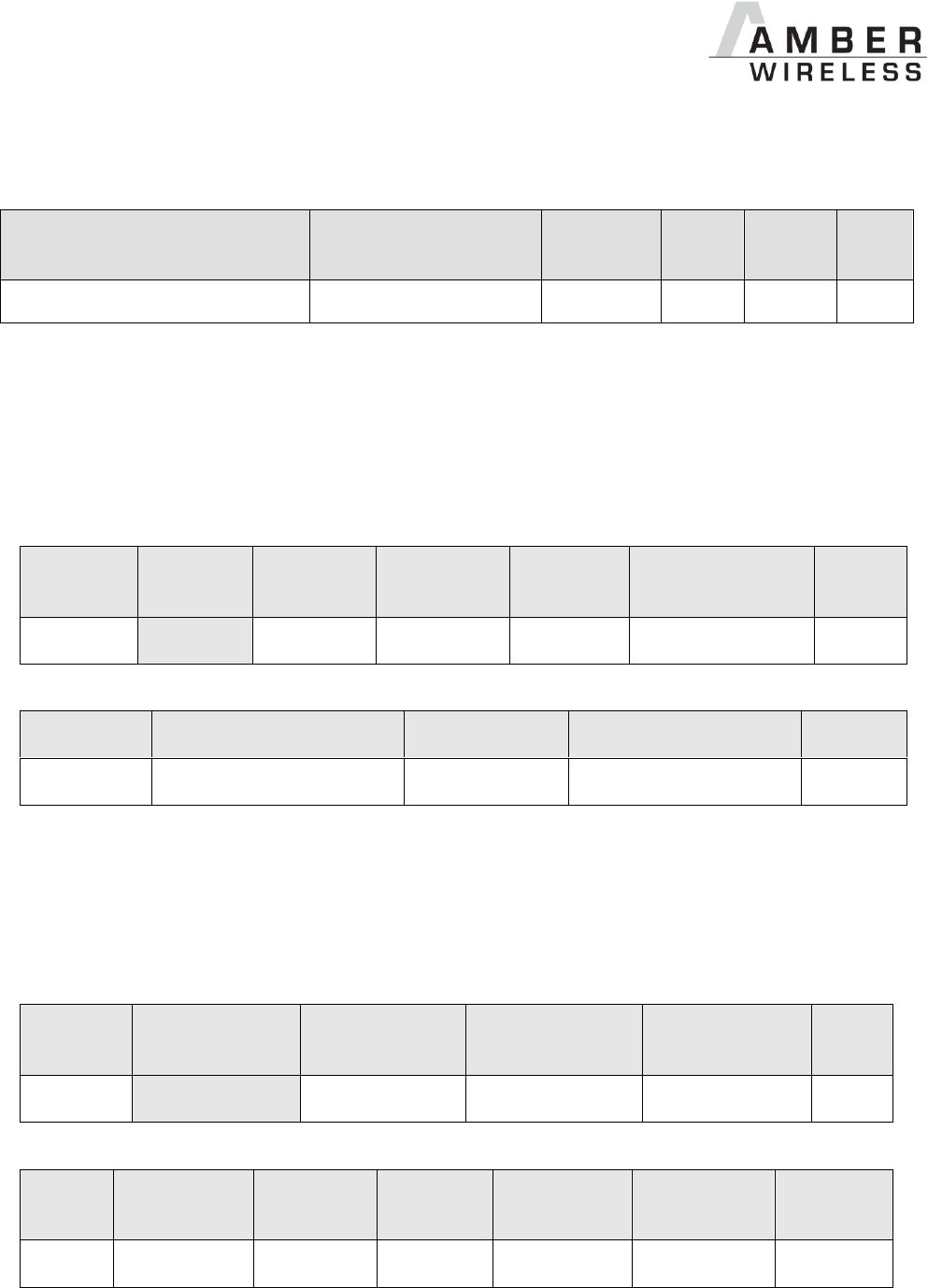
AMB9625_MA_1_0 Page 78 of 107 Date: 09/2017
Successfully read the value of UART_Baudrate as 115200 Baud.
9.2.24 UART_Databits
Designation
Summary
Permissible
values
Default
value
Memory
position
Length
UART_Databits
Number of data bits
7,8
8
84
1
An 8 bit field that contains the number of data bits on the communication interface. Supported
values are 7 and 8.
9.2.24.1 Example 1:
Set the parameter UART_Databits to 8.
Command:
Start
signal
Command
Length + 2
Memory
Position
Length
Parameter
CS
0x02
0x09
0x03
0x54
0x01
0x08
0x55
Response:
Start signal
Command | 0x40
Length
Status
CS
0x02
0x49
0x01
0x00
0x4A
Request successfully received and processed
9.2.24.2 Example 2:
Read the UART_Databits from memory position 84 and length 1.
Command:
Start
signal
Command
Length
Memory Position
Amount of
Bytes
CS
0x02
0x0A
0x02
0x54
0x01
0x5F
Response:
Start
signal
Command |
0x40
Length + 2
Memory
Position
Length
Parameter
CS
0x02
0x4A
0x03
0x54
0x01
0x08
0x16
Successfully read the value of UART_Databits as 8.
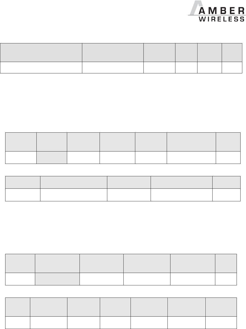
AMB9625_MA_1_0 Page 79 of 107 Date: 09/2017
9.2.25 UART_Parity
Designation
Summary
Permissible
values
Default
value
Memory
position
Length
UART_Parity
Parity
0,1,2
0
85
1
An 8 bit field that contains the parity for the communication interface. Values of 0 (no parity), 1
(even parity) and 2 (odd parity) are supported.
9.2.25.1 Example 1:
Set the parameter UART_Parity to 0 (no parity).
Command:
Start
signal
Command
Length + 2
Memory
Position
Length
Parameter
CS
0x02
0x09
0x03
0x55
0x01
0x00
0x5C
Response:
Start signal
Command | 0x40
Length
Status
CS
0x02
0x49
0x01
0x00
0x4A
Request successfully received and processed
9.2.25.2 Example 2:
Read the UART_Parity from memory position 85 and length 1.
Command:
Start
signal
Command
Length
Memory Position
Amount of
Bytes
CS
0x02
0x0A
0x02
0x55
0x01
0x5E
Response:
Start
signal
Command |
0x40
Length + 2
Memory
Position
Length
Parameter
CS
0x02
0x4A
0x03
0x55
0x01
0x00
0x1F
Successfully read the value of UART_Parity as 0.

AMB9625_MA_1_0 Page 80 of 107 Date: 09/2017
9.2.26 UART_Stoppbits
Designation
Summary
Permissible
values
Default
value
Memory
position
Length
UART_Stoppbits
Stop bits
1,2
1
86
1
An 8 bit field that contains the number of stop bits for the communication interface. Supported
are 1 and 2 stop bits.
9.2.26.1 Example 1:
Set the parameter UART_Stoppbits to 1.
Command:
Start
signal
Command
Length + 2
Memory
Position
Length
Parameter
CS
0x02
0x09
0x03
0x56
0x01
0x01
0x5E
Response:
Start signal
Command | 0x40
Length
Status
CS
0x02
0x49
0x01
0x00
0x4A
Request successfully received and processed
9.2.26.2 Example 2:
Read the UART_Stoppbits from memory position 86 and length 1.
Command:
Start
signal
Command
Length
Memory Position
Amount of
Bytes
CS
0x02
0x0A
0x02
0x56
0x01
0x5D
Response:
Start
signal
Command |
0x40
Length + 2
Memory
Position
Length
Parameter
CS
0x02
0x4A
0x03
0x56
0x01
0x01
0x1D
Successfully read the value of UART_Stoppbits as 1.

AMB9625_MA_1_0 Page 81 of 107 Date: 09/2017
9.2.27 RF_ConfigIndex
Designation
Summary
Permissible
values
Default
value
Memory
position
Length
RF_ConfigIndex
Configuration index
3 and 4
3
92
1
An 8 bit field that addresses the applied RF configuration.
RF_ConfigIndex
Data rate
(gross) [kcps]
Freq. range
[kHz]
Modulation
Max packet time for
repeater mode [ms]
3
38.4
20
GFSK
40
4
100
47
GFSK
20
Table 10 RF profiles
9.2.27.1 Example 1:
Set the RF_ConfigIndex to 4.
Command:
Start
signal
Command
Length + 2
Memory Position
Length
Parameter
CS
0x02
0x09
0x03
0x5C
0x01
0x04
0x51
Response:
Start signal
Command | 0x40
Length
Status
CS
0x02
0x49
0x01
0x00
0x4A
Request successfully received and processed
9.2.27.2 Example 2:
Read the RF_ConfigIndex from memory position 92 and length 1.
Command:
Start
signal
Command
Length
Memory Position
Amount of
Bytes
CS
0x02
0x0A
0x02
0x5C
0x01
0x57
Response:

AMB9625_MA_1_0 Page 82 of 107 Date: 09/2017
Start
signal
Command |
0x40
Length + 2
Memory
Position
Length
Parameter
CS
0x02
0x4A
0x03
0x5C
0x01
0x03
0x15
Successfully read the value of RF_ConfigIndex as 3.
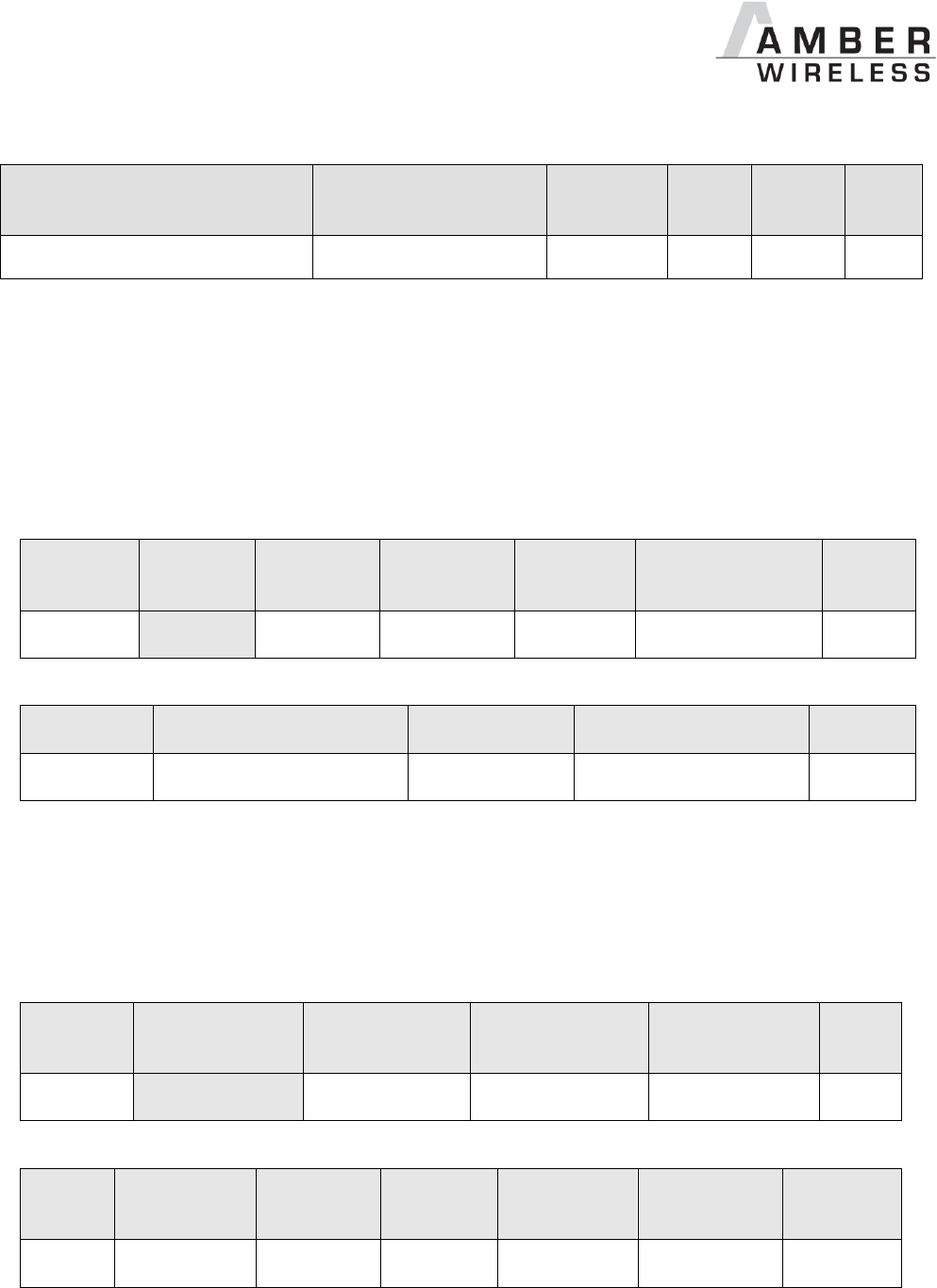
AMB9625_MA_1_0 Page 83 of 107 Date: 09/2017
9.2.28 RF_CCADisabled
Designation
Summary
Permissible
values
Default
value
Memory
position
Length
RF_CCADisabled
Clear channel assessment
0,1
1
93
1
An 8 bit field that disables the channel access via clear channel assessment.
The default value is 1 that means CCA disabled.
9.2.28.1 Example 1:
Set the parameter RF_CCADisabled to 0 (CCA enabled).
Command:
Start
signal
Command
Length + 2
Memory
Position
Length
Parameter
CS
0x02
0x09
0x03
0x5D
0x01
0x00
0x54
Response:
Start signal
Command | 0x40
Length
Status
CS
0x02
0x49
0x01
0x00
0x4A
Request successfully received and processed
9.2.28.2 Example 2:
Read the parameter RF_CCADisabled from memory position 93 and length 1.
Command:
Start
signal
Command
Length
Memory Position
Amount of
Bytes
CS
0x02
0x0A
0x02
0x5D
0x01
0x56
Response:
Start
signal
Command |
0x40
Length + 2
Memory
Position
Length
Parameter
CS
0x02
0x4A
0x03
0x5D
0x01
0x00
0x17
Successfully read the value of UART_CCADisabled as 0 (which means CCA is enabled).

AMB9625_MA_1_0 Page 84 of 107 Date: 09/2017
9.2.29 RF_CCACheckTime
Designation
Summary
Permissible
values
Default
value
Memory
position
Length
RF_CCACheckTime
LSB (Index 95) und MSB(Index 96)
Observation time [ms]
0-60000
5
94
2
A 16 bit field that contains the time in milliseconds for which the channel with activated CCA has
to be observed and identified as free before channel access can take place.
If CCA is used to implement LBT, to be not effected by the duty cycle requirements, the
parameters have to be chosen in accordance with EN 300 220, and for systems with sporadic
bursts of small data packets in accordance with EN 301 391.
9.2.29.1 Example 1:
Set the RF_CCACheckTime to 10ms.
Command:
Start
signal
Command
Length + 2
Memory
Position
Length
Parameter
CS
0x02
0x09
0x04
0x5E
0x02
0x0A 0x00
0x59
Response:
Start signal
Command | 0x40
Length
Status
CS
0x02
0x49
0x01
0x00
0x4A
Request successfully received and processed.
9.2.29.2 Example 2:
Read the RF_CCACheckTime from memory position 94 and length 2.
Command:
Start
signal
Command
Length
Memory Position
Amount of
Bytes
CS
0x02
0x0A
0x02
0x5E
0x02
0x56
Response:
Start
signal
Command |
0x40
Length + 2
Memory
Position
Length
Parameter
CS
0x02
0x4A
0x04
0x5E
0x02
0x05 0x00
0x15
Successfully read the value of RF_CCACheckTime as 5 ms.

AMB9625_MA_1_0 Page 85 of 107 Date: 09/2017
10 Device addressing and wireless monitoring
To connect several modules to networks or to send data to specific devices, the
AMB9625/AMB9665 supports the so called address mode. The corresponding user setting
parameter MAC_AddrMode determines whether all modules in range, or all modules in a
network or a single module with a fixed address is supposed to receive a certain message.
The address resolution can be disabled ("packet sniffer") with bit 7 in the CfgFlags. A module
configured in this way will receive all data packets and forward them to the serial interface,
regardless of the addressing mode. In sniffer mode, the module does not send any
acknowledgement.

AMB9625_MA_1_0 Page 86 of 107 Date: 09/2017
11 Radio parameters
The RF parameters are configured with the RF_ConfigIndex as well as with
PHY_DefaultChannel and PHY_PaPower.
Further the volatile runtime parameter MAC_RuntimeChannel can also be changed with the
corresponding command during the runtime. This leads to the adoption of this parameters with
the next packet transmit or receive. The parameters PHY_PAPOWER and MAC_RuntimePtx are
numbers in complement of two.
The default configuration consists of a data rate of 38.4 kcps (RF_ConfigIndex = 3), a
frequency of 915.00 MHz (PHY_DefaultChannel = 226) and a value of 2 for PHY_PAPOWER.
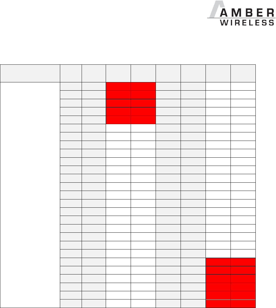
AMB9625_MA_1_0 Page 87 of 107 Date: 09/2017
11.1 Channel assignment
Red marked channels are not to be selected by the user configuration.
Band
Channel
Frequency
MHz
38.4
kBaud
(index 3)
100
kBaud
(index 4)
Channel
Frequency
MHz
38.4
kBaud
(index 3)
100
kBaud
(index 4)
200
902.00
226
915.00
201
902.50
227
915.50
202
903.00
228
916.00
203
903.50
229
916.50
204
904.00
230
917.00
205
904.50
231
917.50
206
905.00
232
918.00
207
905.50
233
918.50
208
906.00
234
919.00
209
906.50
235
919.50
210
907.00
236
920.00
211
907.50
237
920.50
212
908.00
238
921.00
213
908.50
239
921.50
214
909.00
240
922.00
215
909.50
241
922.50
216
910.00
242
923.00
217
910.50
243
923.50
218
911.00
244
924.00
219
911.50
245
924.50
220
912.00
246
925.00
221
912.50
247
925.50
222
913.00
248
926.00
223
913.50
250
926.50
224
914.00
251
927.00
225
914.50
252
927.50
253
928.00
Table 11 Overview of the channels with remark relating to compliance with 50 Ohm wired.
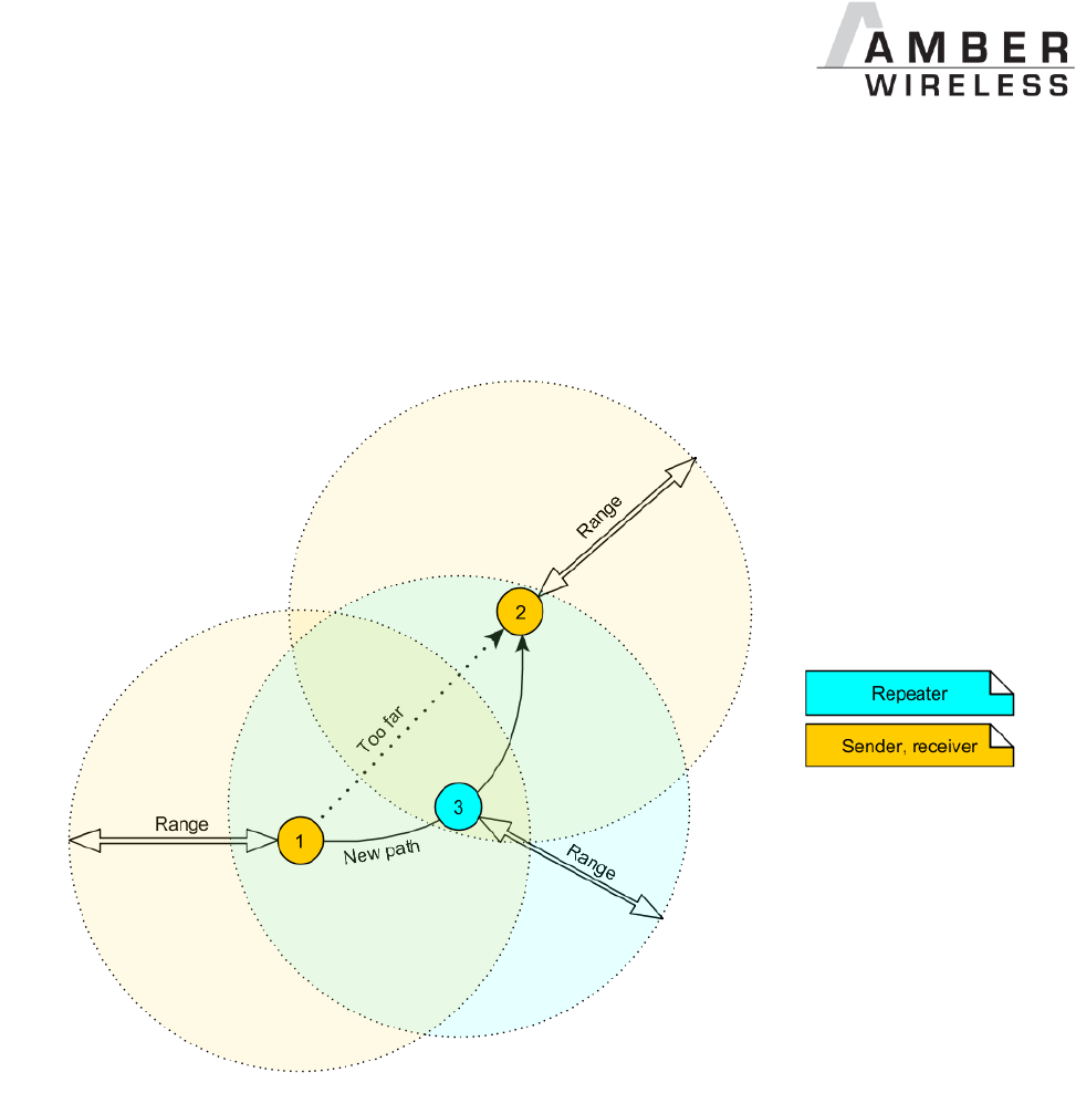
AMB9625_MA_1_0 Page 88 of 107 Date: 09/2017
12 Using the repeater functionality
The AMB9625/AMB9665 module can be run as a repeater to artificially extend the range of
sending devices in an existing network. This feature is available in all firmwares equal or newer
than version 3.4.0.
Figure 2 Range extention using repeaters
If the module is configured as repeater it can be simply added to existing wireless networks
consisting of AMB9625/AMB9665 modules. With this, the network uses the so called “flooding
technique” to deliver data packets from their source to their destination device.
The repeater module itself simply listens to the configured channel and forwards all received
packets, whose destination address does not coincide with the repeater’s source address or
which are send broadcast. Thereby a random delay (see RP_NumSlots) is used to avoid RF
packet collision. To reduce traffic on the frequency channel, each repeater device checks before
repetition, if the channel is free and whether it has already sent this packet before or not. Thus
every repeater sends each packet only once.
In a network with NumRP repeater devices, each data packet is repeated NumRP times.
Therefore each packet that is send from node A to node B forces a traffic of NumRP+1 data
packets in total on the frequency channel.

AMB9625_MA_1_0 Page 89 of 107 Date: 09/2017
Besides of this, a AMB9625/AMB9665 that is configured as repeater supports also the functions
of a standard module. Thus it can receive data and can initiate the data transmission to other
modules.
12.1.1 Setup of the network and repeater device
The repeater mode can be enabled with setting bit 1 in the RpFlags.
As ACKs are not supported by the Repeater-Mode all network members must make
sure that the UserSettings value of MAC_NumRetrys is set to 0.
The Repeater mode will automatically select OpMode 16 (Command mode). The
transparent mode is not supported when repeater mode is selected.
If the AMB9625/AMB9665 device is configured as repeater, the following notes have to be
considered:
Requirements on the network:
The repeater devices have to be line-powered (no batterie), since due to packet
repetition it demands more energy.
Depending on the data rate, each repeater should repeat a maximum of 2-5 packets per
second to give a good chance that the repeater is not busy with repeating when already
a new packet arrives for repetition. Otherwise, packets can get lost. Please setup your
network such that this requirement is fulfilled. More packets per second will result in
more packet loss as the collision propability is increased.
If the network consists of several layers of repeaters, each layer delays the packet
transmission additionally.
To setup the network all participants have to use the same RF_ConfigIndex,
PHY_DefaultChannel and MAC_AddrMode.
Information for the repeater device:
Clear Channel Assessment (CCA) is enabled, thus the user setting RF_CCADisabled
is ignored. CCA is necessary to fullfil the corresponding duty cycle.
The repeater module operates in command mode.
Acknowlegdements (ACK) of successfully received packets are blocked. If an ACK is
requested by the sending module, the request is ignored. Furthermore, the repeater
does not request any ACK, when repeating a packet.
The “packet sniffer” mode cannot run at the same time as the module is in repeater
mode. Thus the bit 7 in the CfgFlags is ignored.
Each time a packet has been repeated a CMD_REPEAT_IND is printed over UART.
Depending on the address mode the address of the involved devices is placed in the
CMD_REPEAT_IND telegram. With this the original sender of the rf packet and the
device, that is supposed to receive the packet, can be identified.
Information for the sending and receiving devices:
The senders should send less frequently to avoid packet collision on the frequency
channel and to not exceed the duty cycle.
The repeater devices do not support the AMB9625/AMB9665 feature of ACKs for the
successful reception of the packets. Thus the sender will never receive ACKs if
requested. To ensure that transmitted packets are successfully received by the
destination device, the network administrator has to integrate his own acknowledging
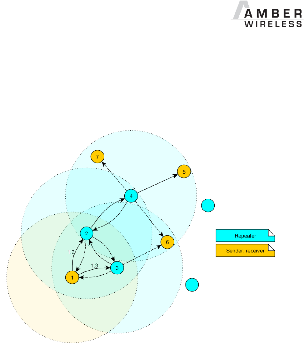
AMB9625_MA_1_0 Page 90 of 107 Date: 09/2017
feature in the customer’s application. To be sure that the sender does not request ACKs
the user setting MAC_NumRetrys must be set to 0.
Every repeater sends each packet only once. But receivers can receive each packet
several times (sent by different repeaters), if there are packets of different content in the
network temporally close to each other. Thus, on the side of the receiving device, a
mechanism can be implemented that filters double packets.
12.1.2 Example network
Figure 3 Example network
In the example network shown above, the goal is to send a packet from device 1 to 5. Without
the repeater devices, this would be impossible. The steps are as follows:
A. Sender 1 sends a packet.
a. Repeater 2 and 3 receive and accept it at the same time.
B. Device 2 and 3 delay the packet.
a. Repeater 3 sends the packet.
i. Sender 1 and 6 do not accept it, since their addresses are wrong
(unequal 5).
ii. Repeater 2 does not accept it, since it has been already received before
(1.2).

AMB9625_MA_1_0 Page 91 of 107 Date: 09/2017
b. Repeater 2 sends the packet.
i. Repeaters 3 does not accept it, since it has been already received before
(1.3).
ii. Sender 1 does not accept it, since its address is wrong (unequal 5).
iii. Repeater 4 receives and accepts the packet.
C. Repeater 4 delays and sends the packet.
a. Sender 6 and 7 do not accept it, since their addresses are wrong (unequal 5).
b. Repeater 2 does not accept it, since it has been already received before (1.2).
c. Receiver 5 accepts it and its successfully delivered (address equals 5)
Please note that the packet forwarded by repeater 2 and 3 would collide in the frequency
channel, if they wouldn’t be randomly delayed (see RP_NumSlots in 9.2.22).
12.1.3 Application in parallel networks
As described above, a repeater device forwards all packets that are received before. If a
network needs to have a bigger throughput of data, a parallel network can be set up, that
relaxes the stress of the primal network. To do so, all sending, receiving and repeater devices of
the parallel network are configured to use a new channel, such that the primal network is not
affected at all by the traffic of the parallel network.

AMB9625_MA_1_0 Page 92 of 107 Date: 09/2017
13 Battery powered operation
The TRX_DISABLE pin can set the module to one of two different modes of operation.
13.1 Active mode
When TRX_DISABLE is low, the module is permanently ready to receive and forward data via
UART or wireless transmission. The module will switch to one of the internal LPM after having
processed any pending data transmission, i.e. /RTS must be low.
13.2 Stand-by mode
When TRX_DISABLE is high, the operation of the module's transceiver is disabled. Wireless
reception is not possible, but transmission of data is possible. The module will switch to one of
the internal LPM as long as no data will be transmitted. A UART data rate of more than 9600
baud will result in a higher current consumption.
The CfgFlag Bit 4 can modify this behaviour (see chapter 9.2.20).

AMB9625_MA_1_0 Page 93 of 107 Date: 09/2017
14 Timing parameters
14.1 Reset behaviour
Following a reset, a low on the /RTS pin signals that the module is ready for operation.
This level is however only valid, after the delay required for the internal initialisation of the
processor (a few µs).
14.1.1 Power-on reset
After switching the supply voltage and releasing the /RESET pin (if wired), the time until the
module is ready for operation can last up to 1 s.
14.1.2 Reset via /RESET pin
To force a module restart by means of the /RESET pin, it must first be drawn to low for at least
10 ms.
After the pin is released, /RTS will switch to high after 100 µs at the latest. Since the start-up
time for the clock quartz does not apply in this case, the time until the module is ready for
operation is reduced to a couple of ms. During this time, the processor clock-rate will be
calibrated, which takes anyway between 2 and 20 ms depending on the supply voltage and
temperature.
Recommended procedure: After the /RESET pin is released, wait for 2 ms for the low level on
the /RTS pin. Subsequently, additional 100 µs are required until the system is ready.
14.1.3 Reset as result of a serious error condition
If the module runs in a serious error condition, a software reset is executed. In this case, the
module starts up automatically and can be used again. The volatile runtime settings are reset to
default, see chapter 8.
14.2 Latencies when leaving the LPM
The module enters a LPM as soon as no data-transmission request is received via serial and
RF interface.
If the device returns from such a mode, all internal settings like the channel calibration values
and noise levels have been retained, such that the module is ready after a few µs. Also here a
low signal at the /RTS indicates that the module is ready for operation.
14.3 Latencies during data transfer / packet generation
The data transfer is always buffered, i.e. data received via UART is buffered in the module until
a specific event occurs. Subsequently, the UART reception is interrupted (flow control with /RTS
signal), and the payload data is passed to the internal memory of the wireless transceiver
(FIFO).
By using several UART buffers the time during which the UART is not receiving can be
minimized.

AMB9625_MA_1_0 Page 94 of 107 Date: 09/2017
The channel access method adds additional latency. This can be configured in the user
settings.
The wireless transmission starts as soon as the first data is available in the transceiver memory.
During the continuous wireless transmission the remaining payload data is transmitted byte by
byte.
On the receiver side, the FIFO is read as soon as an incoming packet is detected.
If the module detects a packet that requires an ACK, the ACK is sent directly after the packet
reception. The channel access method is always deactivated for ACKs.
In combination with a suitable packet generation method, this procedure enables the
minimisation of the latencies resulting from buffering.

AMB9625_MA_1_0 Page 95 of 107 Date: 09/2017
15 Firmware update
We highly recommend to have pads/connectors for realizing these (external) uart
connection on any customer PCB.
15.1 Update using UART interface
As long as a firmware is running on the module the module can be updated with the PC utility
"AMBER Config Center” (ACC V3) via the serial interface.
If the module is not directly connected to a PC, the UART should be made accessible, e.g. by
means of suitable connectors. Only the UTDX, URXD and GND signals are needed for this
connection. An adapter is required for a PC connection (e.g. the FTDI TTL-323R-3V3 uart to
usb converter).
The /RESET signal shall be connectable to GND for performing a reset of the module (e.g.
using a push-button which pulls to GND when pressed)
15.2 Update using JTAG or Spy-Bi-Wire
Using one of this two interface options allows performing a fail-safe firmware update even in
case of a broken firmware or malconfiguration.
The user needs hardware and software tools to be able to perform this procedure. In detail
those are:
Flash adapter for MSP430 µC’s (e.g. from TI, Elprotronic or Olimex), caution: not every
adapter supports both described connection methods. Recommended adapter:
“Elprotronic Flash Pro 430”
In case of SPY-Bi-Wire a dedicated connector with some passive parts is needed (see
the documentation of the flash adapter you use) this connector may vary from µC to µC
In general /Reset, GND and VCC are needed for such connections
JTAG is supported through the module’s pads 6(J.0), 7(J.1), 8(J.2), 18(J.3)
SPY-Bi-wire is supported through pad 17 (TEST pin of the µC)
The manual of the EV-Board gives an example of a JTAG connection with a 2*7 Pin connector
for the MSP430F2xxx and MSP430F5xxx Platforms.

AMB9625_MA_1_0 Page 96 of 107 Date: 09/2017
16 Firmware history
Version 3.4.0
First release for 915MHz Band as a branch of AMB8626 V3.4.0 firmware for FCC -2dBm
compatibility
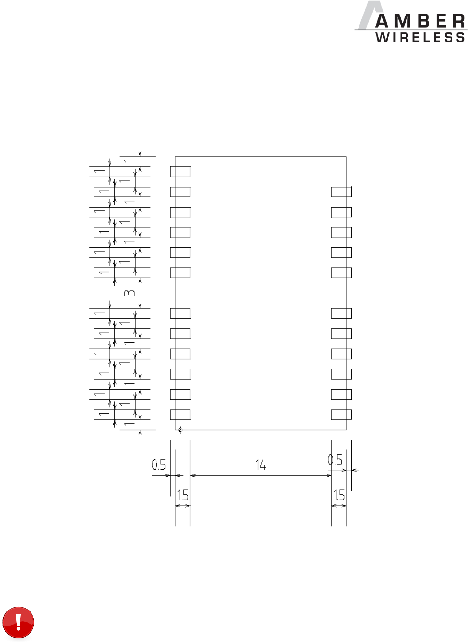
AMB9625_MA_1_0 Page 97 of 107 Date: 09/2017
17 Hardware integration
17.1 Footprint
Figure 4 Footprint AMB9625 (also applicable for AMB8426), [mm]
To avoid the risk of short circuits between VCC and GND, a minimum clearance of at
least 14 mm between the opposing pad rows has to be maintained!
AMB9625_MA_1_0 Page 98 of 107 Date: 09/2017
18 Design in guide
18.1 Advice for schematic and layout
For users with less RF experience it is advisable to closely copy the relating evaluation board
with respect to schematic and layout, as it is a proven design. The layout should be conducted
with particular care, because even small deficiencies could affect the radio performance and its
range or even the conformity.
The following general advice should be taken into consideration:
A clean power supply is strongly recommended. Interference, especially oscillation can
severely restrain range and conformity.
Variations in voltage level should be avoided.
LDOs, properly designed in, usually deliver a proper regulated voltage.
Blocking capacitors and a ferrite bead in the power supply line can be included to filter
and smoothen the supply voltage when necessary.
No fixed values can be recommended, as these depend on the circumstances of the
application (main power source, interferences etc.).
Frequently switching the module on and off, especially with a slowly changing voltage
level of the power supply, can lead to erratic behavior, in rare cases even as far as
damaging the module or the firmware. The use of an external reset IC can solve this
matter.
Elements for ESD protection should be placed on all Pins that are accessible from the
outside and should be placed close to the accessible area. For example, the RF-Pin is
accessible when using an external antenna and should be protected.
ESD protection for the antenna connection must be chosen such as to have a minimum
effect on the RF signal. For example, a protection diode with low capacitance such as
the LXES15AAA1-100 or a 68 nH air-core coil connecting the RF-line to ground give
good results.
Placeholders for optional antenna matching or additional filtering are recommended.
Again, no fixed values can be recommended, as they depend on the influencing
circumstances of the application (antenna, interferences etc.).
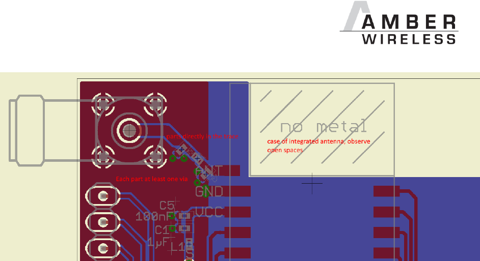
AMB9625_MA_1_0 Page 99 of 107 Date: 09/2017
Figure 5: Layout
To avoid the risk of short circuits and interference there should be no routing underneath
the module on the top layer of the baseboard.
On the second layer, a ground plane is recommended, to provide good grounding and
shielding to any following layers and application environment.
In case of integrated antennas it is required to have areas free from ground. This area
should be copied from the evaluation board.
The area with the integrated antenna must overlap with the carrier board and should not
protrude, as it is matched to sitting directly on top of a 1.5 mm thick PCB.
Modules with integrated antennas should be placed with the antenna at the edge of the
main board. It should not be placed in the middle of the main board or far away from the
edge. This is to avoid tracks beside the antenna.
Filter and blocking capacitors should be placed directly in the tracks without stubs, to
achieve the best effect.
Antenna matching elements should be placed close to the antenna / connector, blocking
capacitors close to the module.
Ground connections for the module and the capacitors should be kept as short as
possible and with at least one separate through hole connection to the ground layer.
ESD protection elements should be placed as close as possible to the exposed areas.
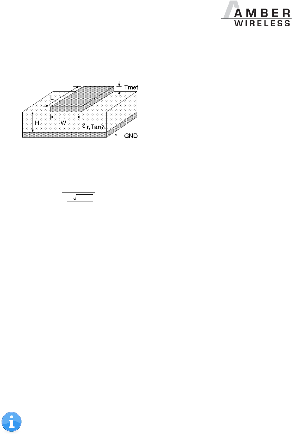
AMB9625_MA_1_0 Page 100 of 107 Date: 09/2017
18.2 Dimensioning of the 50 Ohm microstrip
The antenna track has to be designed as a 50 Ohm feed line.
Figure 6 Dimensioning the antenna feed line as micro strip
The width W for a micro strip can be calculated using the following equation:
met
T
e
H
Wr
87
41.150
98.5
25.1
Equation 1 Parameters of the antenna feeding line
Example: a FR4 material with r = 4.3, a height H = 1000 µm and a copper thickness of Tmet= 18
µm will lead to a trace width of W ~ 1.9 mm. To ease the calculation of the Microstrip line (or
e.g. a coplanar) many calculators can be found in the internet.
As rule of thumb a distance of about 3 x W should be observed between the micro strip
and other traces / ground.
The Microstrip refers to ground, therefore there has to be the ground plane underneath
the trace.
Keep the feeding line as short as possible.
18.3 Antenna solutions
There exist several kinds of antennas, which are optimized for different needs. Chip antennas
are optimized for minimal size requirements but at the expense of range, PCB antennas are
optimized for minimal costs, and are generally a compromise between size and range. Both
usually fit inside a housing. Range optimization in general is at the expense of space. Antennas
that are bigger in size, so that they would probably not fit in a small housing, are usually
equipped with a RF connector. A benefit of this connector may be to use it to lead the RF signal
through a metal plate (e.g. metal housing, cabinet).
As a rule of thumb a minimum distance of Lambda/10 (3.5 cm @ 868 MHz, 1.2 cm @ 2.44
GHz) from the antenna to any other metal should be kept. Metal placed further away will not
directly influence the behavior of the antenna, but will anyway produce shadowing.
Keep the antenna away from large metal objects as far as possible to avoid
electromagnetic field blocking.

AMB9625_MA_1_0 Page 101 of 107 Date: 09/2017
In the following chapters, some special types of antenna are described.
18.3.1 Lambda/4 radiator
An effective antenna is a Lambda/4 radiator. The simplest realization is an 8.6 cm long piece of
wire for 868 MHz, respectively a 3.1 cm long piece of wire for 2.44 GHz. This radiator needs a
ground plane at its feeding point. Ideally, it is placed vertically in the middle of the ground plane.
As this is often not possible because of space requirements, a suitable compromise is to bend
the wire away from the PCB respective to the ground plane. The Lambda/4 radiator has
approximately 40 Ohm input impedance, therefore matching is not required.
18.3.2 Chip antenna
There are many chip antennas from various manufacturers. The benefit of a chip antenna is
obviously the minimal space required and reasonable costs. However, this is often at the
expense of range. For the chip antennas, reference designs should be followed as closely as
possible, because only in this constellation can the stated performance be achieved.
18.3.3 PCB antenna
PCB antenna designs can be very different. The special attention can be on the miniaturization
or on the performance. The benefits of the PCB antenna are their small / not existing (if PCB
space is available) costs, however the evaluation of a PCB antenna holds more risk of failure
than the use of a finished antenna. Most PCB antenna designs are a compromise of range and
space between chip antennas and connector antennas.
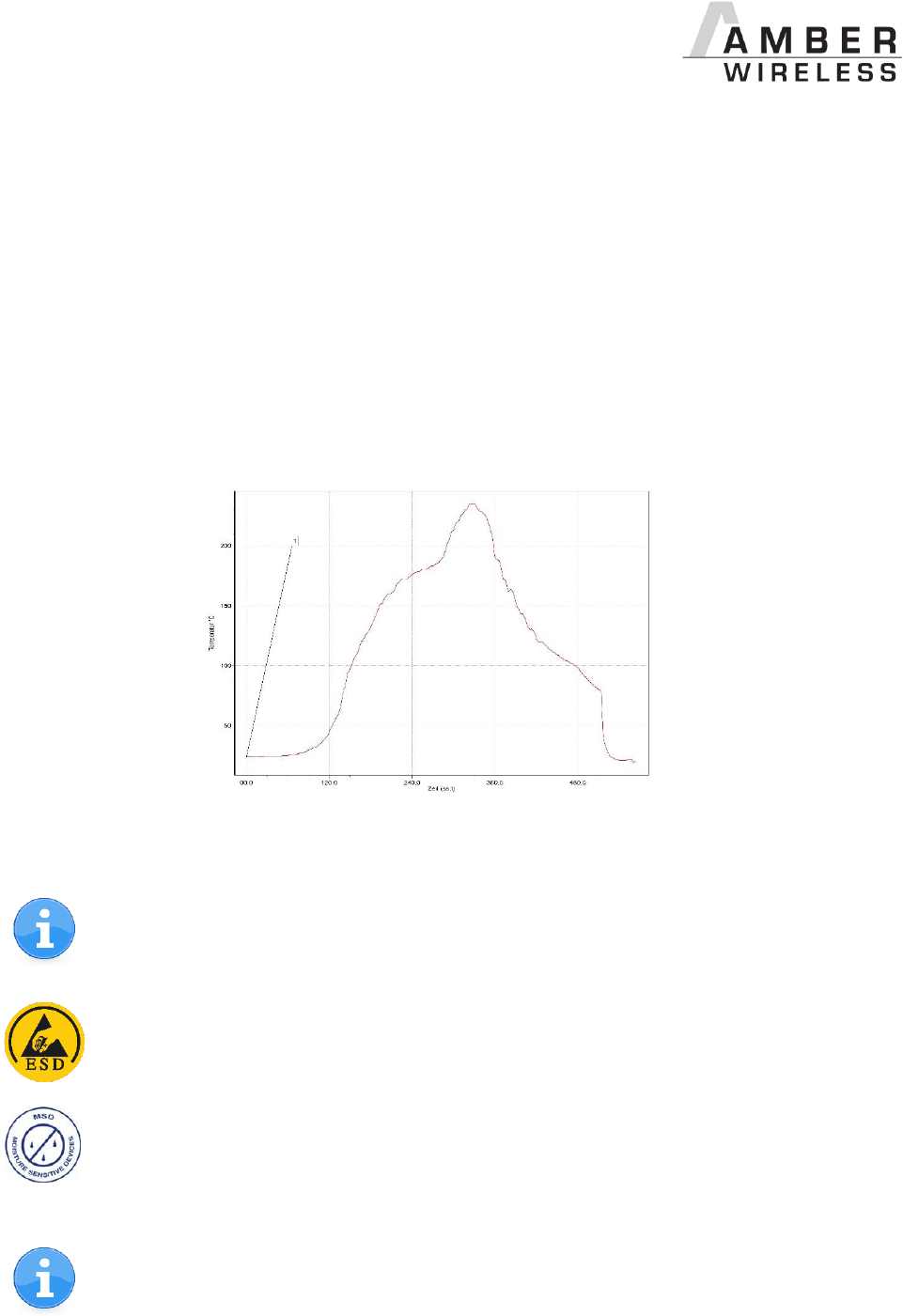
AMB9625_MA_1_0 Page 102 of 107 Date: 09/2017
19 Manufacturing information
The assembly contains moisture sensitive devices of the MSL classification 3. Only the
dry packed Tape & Reel devices are suitable for the immediate processing in a reflow
process.
Further information concerning the handling of moisture sensitive devices, (e.g. drying)
can be obtained from the IPC/ JEDEC J-STD-033.
Recommendations for the temperature profile for the soldering furnace cannot be made,
as it depends on the substrate board, the number and characteristics of the
components, and the soldering paste used (consult your EMS).
Figure 7 shows a soldering curve that had been used for a 31 cm2 carrier board for single-side
assembly.
Figure 7 Example of a temperature profile –
Caution: Must be adjusted to the characteristics of the carrier board!
To ensure the mechanical stability of the modules it is recommended to solder all the
pads of the module to the base board, even if they are not used for the application.
Caution! ESD sensitive device.
Precaution should be taken when handling the device in order to prevent
permanent damage.
MSL 3
Caution! This assembly contains moisture sensitive components.
Precaution should be taken when processing the device according to
IPC/JEDEC J-STD-033.
Since the module itself is not fused the voltage supply shall be coming from a limited
power source according to clause 2.5 of EN 60950-1.

AMB9625_MA_1_0 Page 103 of 107 Date: 09/2017
20 References
[1] „CC1125 Single-Chip Low Cost Low Power RF-Transceiver”, Texas Instruments
[2] „AMB9625 Datasheet”, AMBER wireless GmbH

AMB9625_MA_1_0 Page 104 of 107 Date: 09/2017
21 Regulatory compliance information
21.1 Important notice
The use of RF frequencies is limited by national regulations. The AMB9625 has been designed
to comply with the FCC and IC.
The AMB9625 can be operated without notification and free of charge in the area of USA and
Canada.
Conformity assessment of the final product
The AMB9625 is a subassembly. It is designed to be embedded into other products (products
incorporating the AMB9625 are henceforward referred to as "final products").
It is the responsibility of the manufacturer of the final product to ensure that the final product is
in compliance with the essential requirements of the FCC and IC.
Exemption clause
Relevant regulation requirements are subject to change. AMBER wireless GmbH does not
guarantee the accuracy of the before mentioned information. Directives, technical standards,
procedural descriptions and the like may be interpreted differently by the national authorities.
Equally, the national laws and restrictions may vary with the country. In case of doubt or
uncertainty, we recommend that you consult with the authorities or official certification
organizations of the relevant countries. AMBER wireless GmbH is exempt from any
responsibilities or liabilities related to regulatory compliance.

AMB9625_MA_1_0 Page 105 of 107 Date: 09/2017
21.2 FCC Compliance statement AMB9625
FCC ID: R7TAMB9625
This device complies with Part 15 of the FCC Rules.
Operation is subject to the following two conditions:
(1) this device may not cause harmful interference, and
(2) this device must accept any interference received, including interference that may cause
undesired operation.
(FCC 15.19)
Modifications (FCC 15.21)
Caution: Changes or modifications for this equipment not expressly approved by AMBER
wireless may void the FCC authorization to operate this equipment.
21.3 IC Compliance statement AMB9625
Certification Number: 5136A- AMB9625
This device complies with Industry Canada licence-exempt RSS standard(s). Operation is
subject to the following two conditions: (1) this device may not cause harmful interference, and
(2) this device must accept any interference received, including interference that may cause
undesired operation.
Le présent appareil est conforme aux CNR d'Industrie Canada applicables aux appareils radio
exempts de licence. L'exploitation est autorisée aux deux conditions suivantes : (1) l'appareil ne
doit pas produire de brouillage, et (2) l'utilisateur de l'appareil doit accepter tout brouillage
radioélectrique subi, même si le brouillage est susceptible d'en compromettre le
fonctionnement.
21.4 FCC and IC Requirements to OEM integrators
This module has been granted modular approval. OEM integrators for host products may use
the module in their final products without additional FCC / IC (Industry Canada) certification if
they meet the following conditions. Otherwise, additional FCC / IC approvals must be obtained.
The host product with the module installed must be evaluated for simultaneous transmission
requirements.
The users manual for the host product must clearly indicate the operating requirements and
conditions that must be observed to ensure compliance with current FCC / IC RF exposure
guidelines.
To comply with FCC / IC regulations limiting both maximum RF output power and human
exposure to RF radiation, the maximum antenna gain including cable loss in a mobile-only
exposure condition must not exceed 2dBi.

AMB9625_MA_1_0 Page 106 of 107 Date: 09/2017
A label must be affixed to the outside of the host product with the following statements:
This device contains FCCID: R7TAMB9625
This equipment contains equipment certified under ICID: 5136A-AMB9625
The final host / module combination may also need to be evaluated against the FCC Part 15B
criteria for unintentional radiators in order to be properly authorized for operation as a Part 15
digital device.
If the final host / module combination is intended for use as a portable device (see
classifications below) the host manufacturer is responsible for separate approvals for the SAR
requirements from FCC Part 2.1093 and RSS-102.
OEM Requirements:
The OEM must ensure that the following conditions are met.
End users of products, which contain the module, must not have the ability to alter the
firmware that governs the operation of the module. The agency grant is valid only when the
module is incorporated into a final product by OEM integrators.
The end-user must not be provided with instructions to remove, adjust or install the module.
The Original Equipment Manufacturer (OEM) must ensure that FCC labeling requirements
are met. This includes a clearly visible label on the outside of the final product. Attaching a
label to a removable portion of the final product, such as a battery cover, is not permitted.
The label must include the following text:
Contains FCC ID: R7TAMB9625
The enclosed device complies with Part 15 of the FCC Rules. Operation is subject to
the following two conditions: (i.) this device may not cause harmful interference and
(ii.) this device must accept any interference received, including interference that may cause
undesired operation.
When the device is so small or for such use that it is not practicable to place the statement
above on it, the information required by this paragraph shall be placed in a prominent location in
the instruction manual or pamphlet supplied to the user or, alternatively, shall be placed on the
container in which the device is marketed. However, the FCC identifier or the unique identifier,
as appropriate, must be displayed on the device.
The user manual for the end product must also contain the text given above.
Changes or modifications not expressly approved could void the user's authority to operate
the equipment.
The OEM must ensure that timing requirements according to 47 CFR 15.231(a-c) are met.
The OEM must sign the OEM Modular Approval Agreement with xxxxx
The module must be used with only the following approved antenna(s).

AMB9625_MA_1_0 Page 107 of 107 Date: 09/2017
22 Important information
22.1 Exclusion of liability
AMBER wireless GmbH presumes that the information in this document is correct at the time of
publication. However, AMBER wireless GmbH reserves the right to modify technical
specifications or functions of its products or discontinue the production of these products or the
support of one of these products without any written announcement or notification to customers.
The customer must make sure that the information used is valid. AMBER wireless GmbH does
not assume any liability for the use of its products. Amber wireless GmbH does not grant
licenses for its patent rights or for any other of its intellectual property rights or third-party rights.
Customers bear responsibility for compliance of systems or units in which AMBER wireless
products are integrated with applicable legal regulations.
22.2 Trademarks
AMBER wireless® is a registered trademark of AMBER wireless GmbH.
All other trademarks, registered trademarks, and product names are the exclusive property of
the respective owners.
22.3 Usage restriction
AMBER wireless products are not approved for use in life-supporting or life-sustaining systems
or units or other systems whose malfunction could result in serious bodily injury to the user.
Moreover, AMBER wireless products are not approved for use as key components of any life-
supporting or life-sustaining system or unit whose malfunction could result in the failure of the
life-supporting system or unit or could affect its safety or effectiveness. AMBER wireless
customers who use these products in such applications or sell them for such usage act at their
own risk and must relieve AMBER wireless GmbH from all damages that may result from the
sale for unsuitable purposes or unsuitable usage.
By using AMBER wireless products, the user agrees to these terms and conditions.
Copyright © 2016, AMBER wireless GmbH. All rights reserved.
AMBER wireless GmbH
Phone +49.651.993.550
Email info@amber-wireless.de
Internet www.amber-wireless.de