Wuerth Elektronik eiSos and Co KG AMB9826 AMB9826 User Manual Testreport ETS 300 335
Wuerth Elektronik eiSos GmbH & Co KG AMB9826 Testreport ETS 300 335
UserManual.wiki
>
Wuerth Elektronik eiSos and Co KG
>
AMB9826 User Manual
Users Manual
Navigation menu
Upload a User Manual
Namespaces
Wiki Guide
HTML
PDF
Info
Views
User Manual
Discussion / Help
Navigation
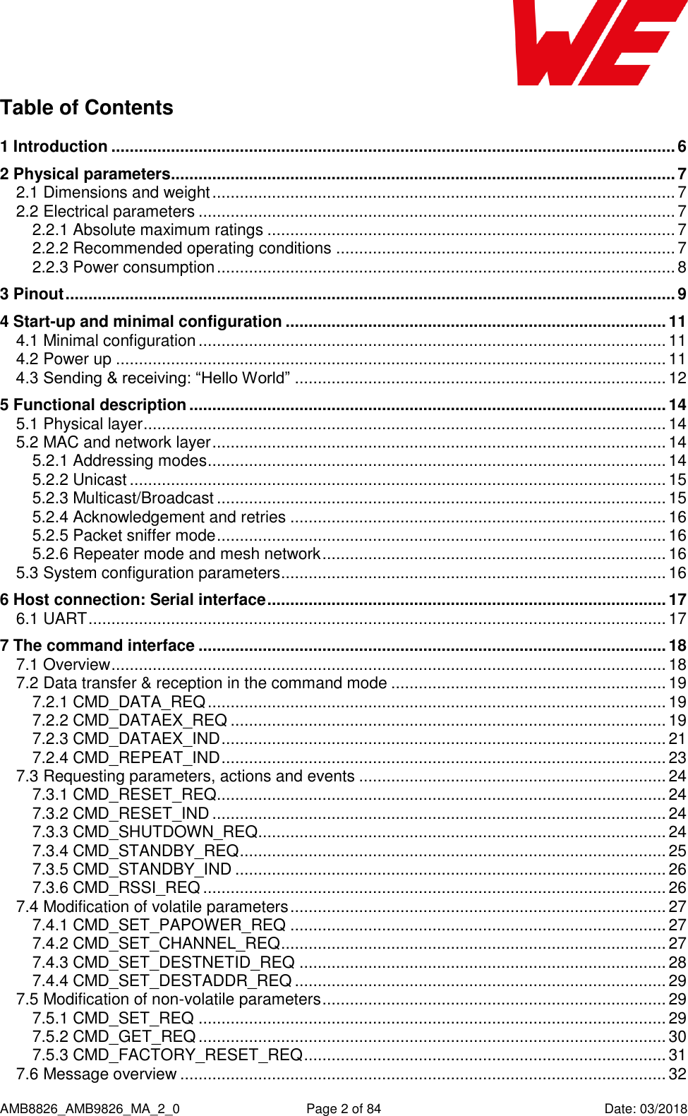
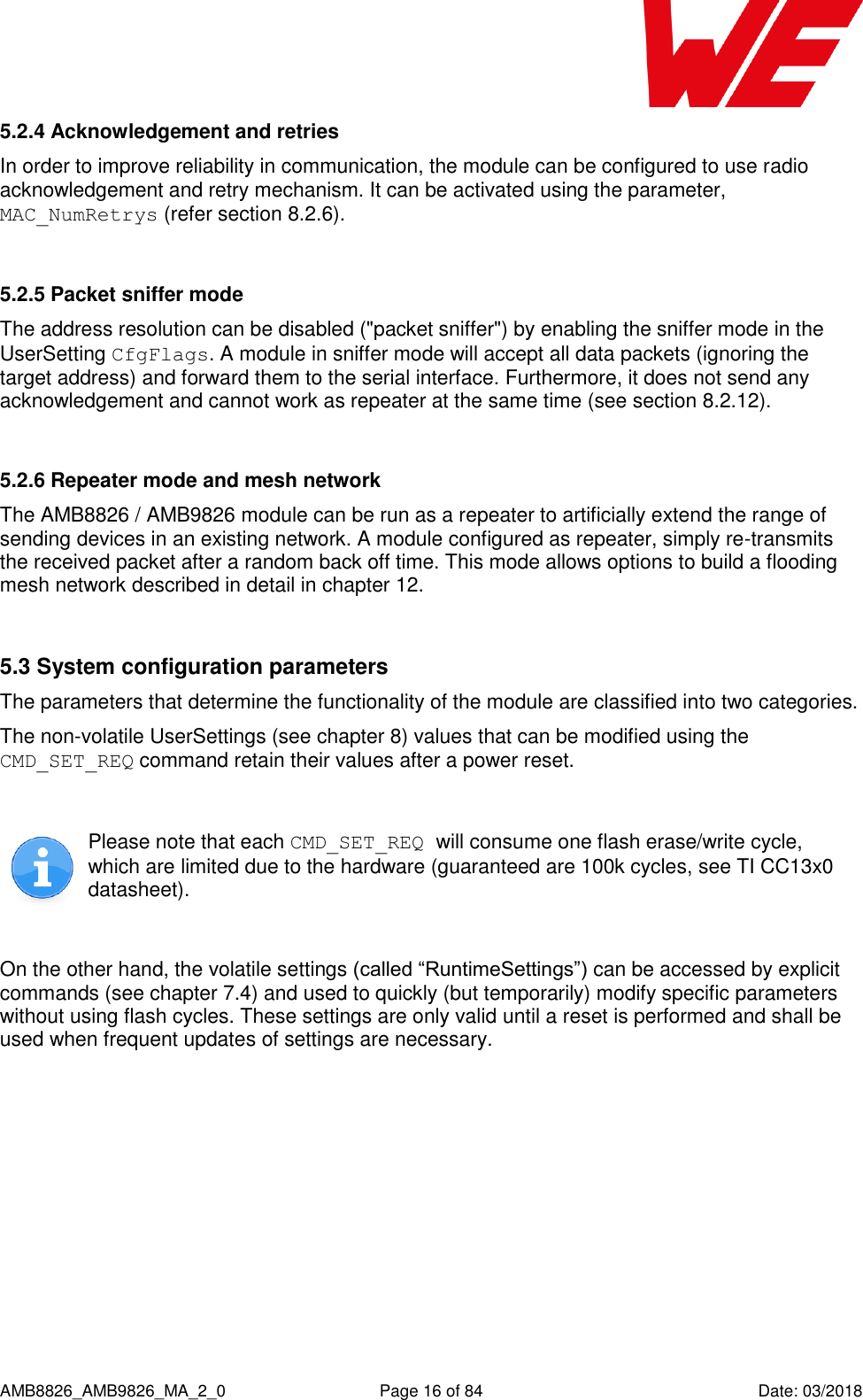
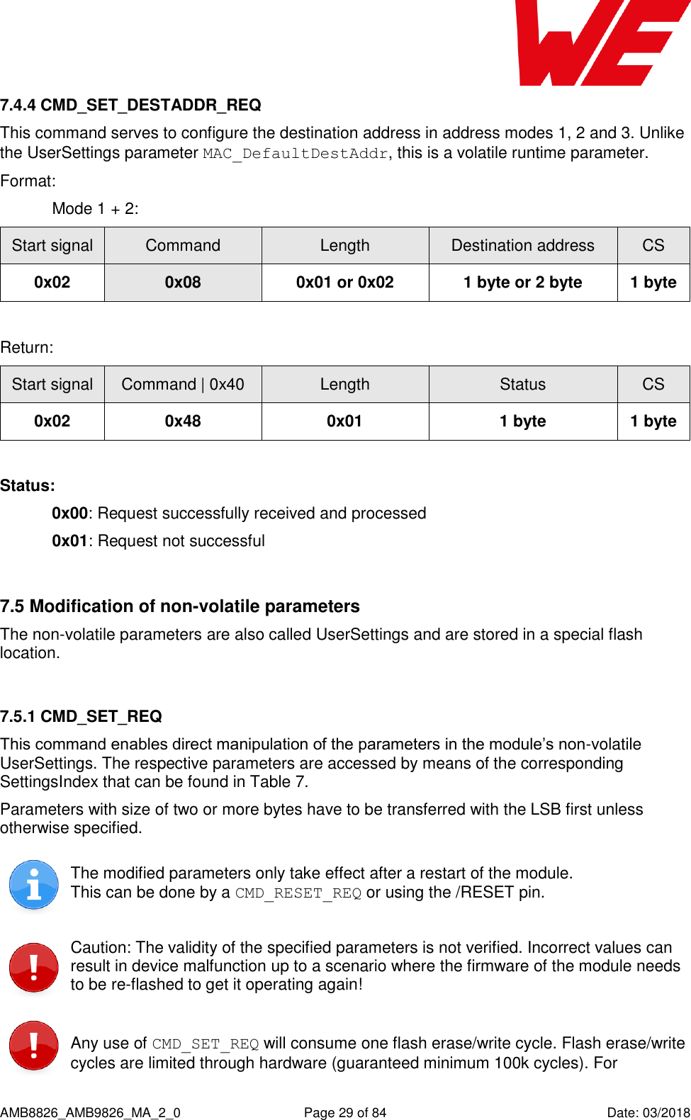
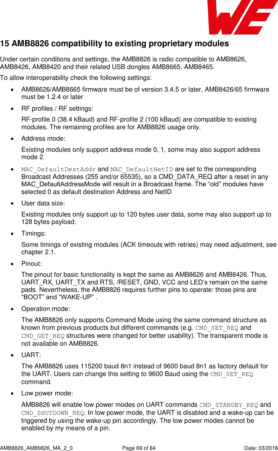
![AMB8826_AMB9826_MA_2_0 Page 5 of 84 Date: 03/2018 Abbreviations and abstract ACK Acknowledgement Acknowledgement pattern confirming the reception of the transmitted data packet CS Checksum DC Duty cycle Relative frequency reservation period LPM Low power mode Operation mode for reduced power consumption. RF Radio frequency Describes everything relating to the wireless transmission Payload The real, non-redundant information in a frame/packet UserSettings Any relation to a specific entry in the UserSettings is marked in a special font and can be found in the respective chapter UART Universal Asynchronous Receiver Transmitter allows communicating with the module of a specific interface. Duty cycle Transmission time in relation of one hour 1% means, channel is occupied for 36 seconds per hour. Hexadecimal [HEX] 0xhh All numbers beginning with 0x are stated as hexadecimal numbers. All other numbers are decimal.](https://usermanual.wiki/Wuerth-Elektronik-eiSos-and-Co-KG/AMB9826/User-Guide-3860924-Page-6.png)
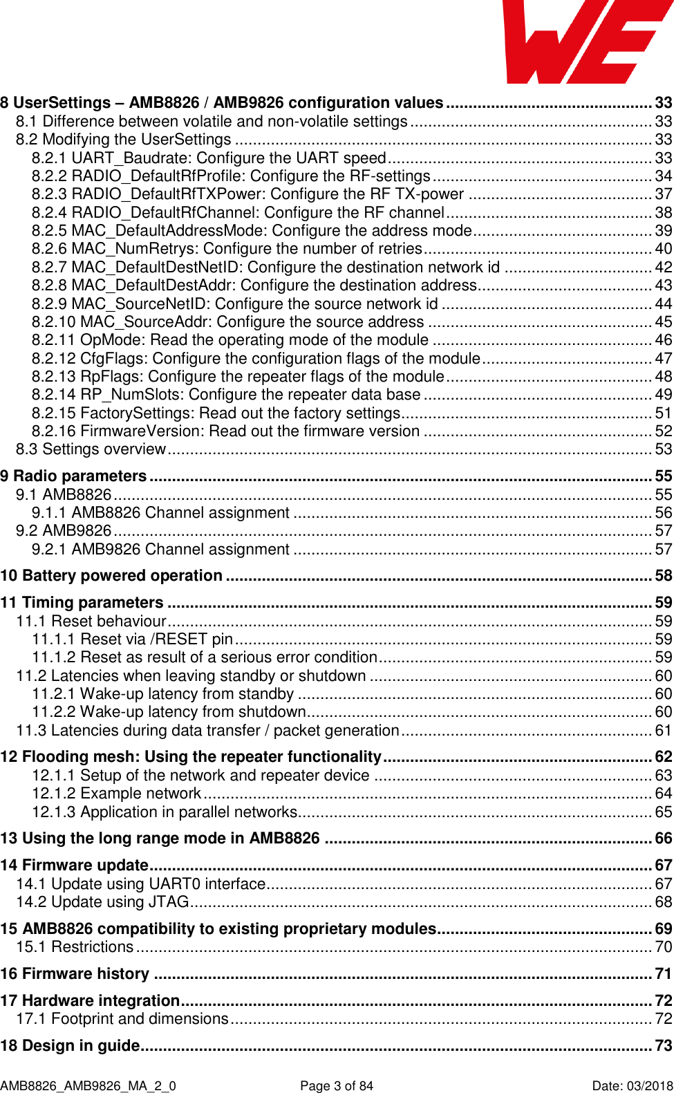
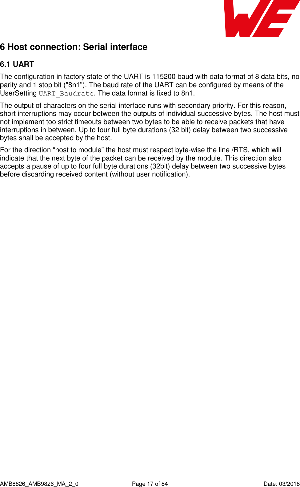
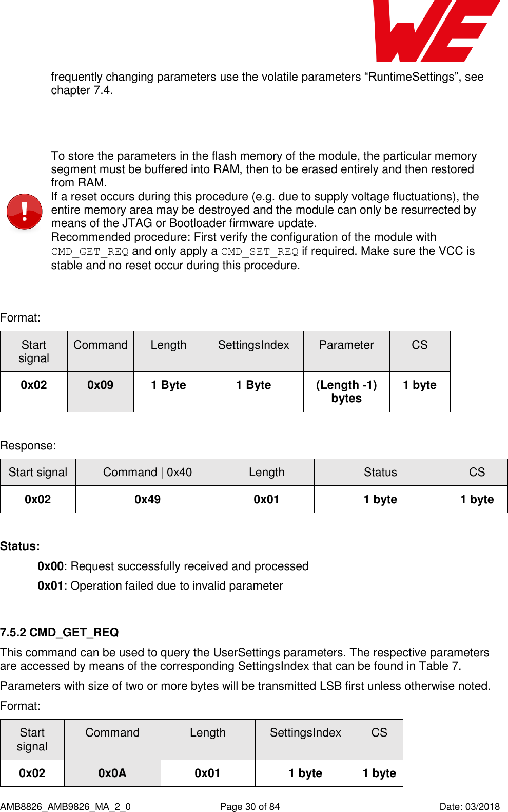
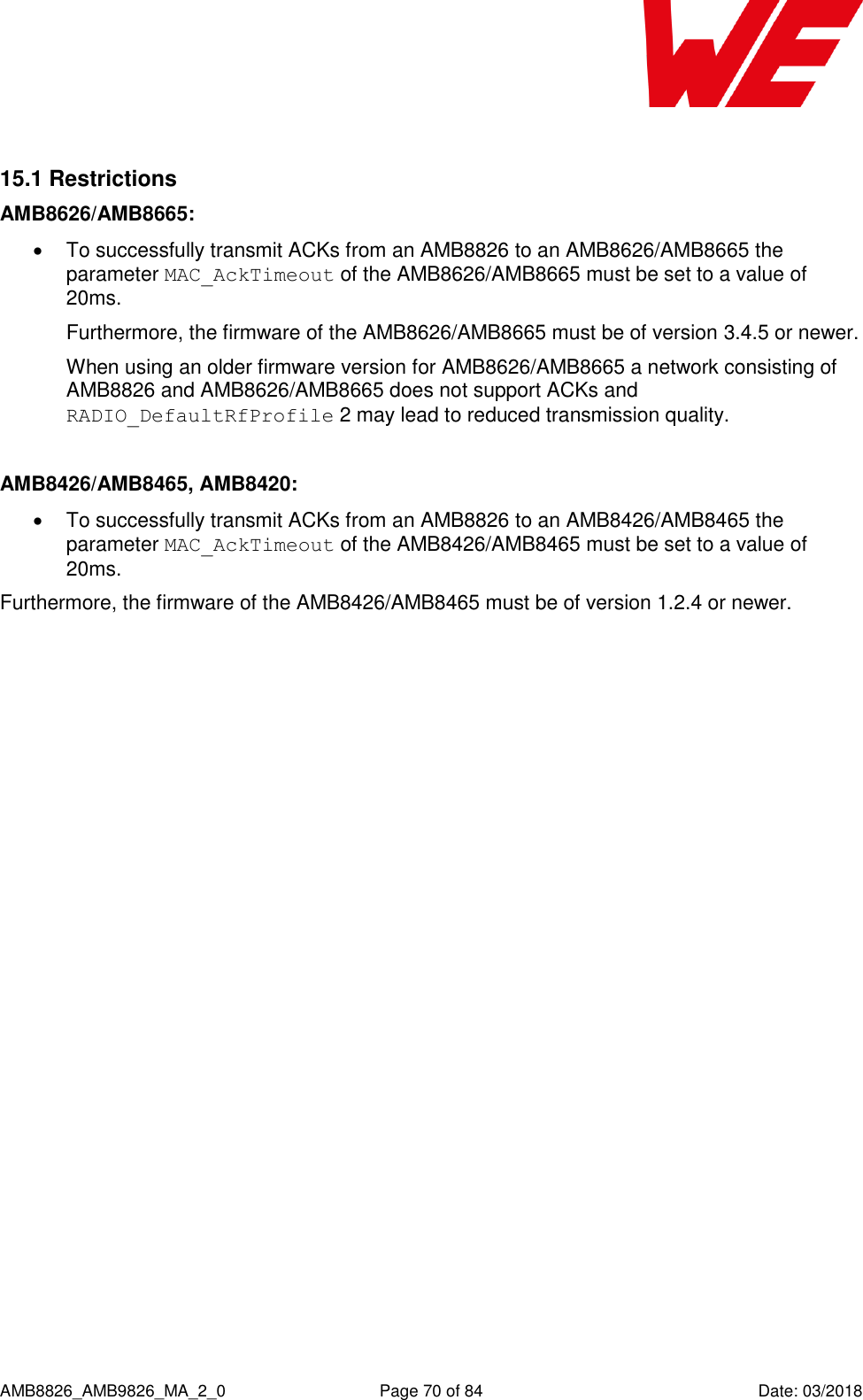
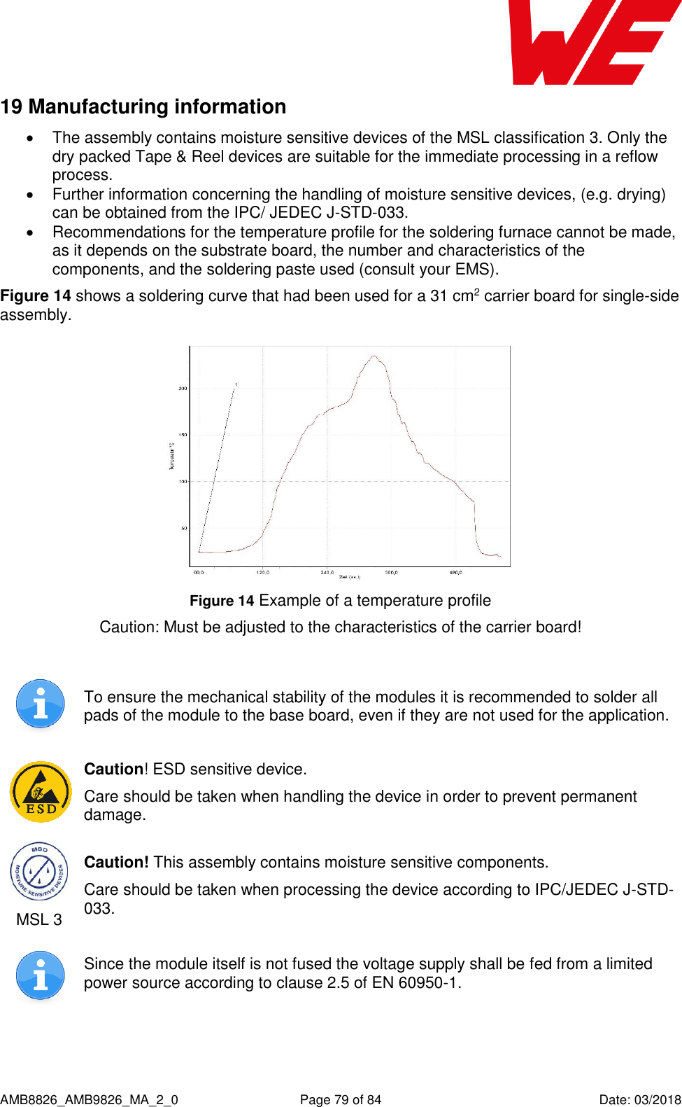
![AMB8826_AMB9826_MA_2_0 Page 8 of 84 Date: 03/2018 2.2.3 Power consumption As a DC/DC voltage regulator is integrated, the current consumption is strongly depending on the supplied voltage level. The Transmit and Receive Currents are depending on the impedance matching, and therefore may vary depending on antenna selection and matching. The indicated values are the complete current consumption for radio and active MCU. Not to be confused with only radio or only cpu core currents, as sometimes stated by others. A stable supply indispensable to ensure valid operating conditions for the module. VDDS = 3.6V, transmit current in boost mode Description typ unit TX current 10 dBm output power TX current 14 dBm output power 17 26 mA RX current 8 mA Low Power (standby) radio off, uart off, rtc running, full RAM retention 1.0 µA Low Power (shutdown) radio off, uart off, rtc off, no RAM retention 0.2 µA Figure 1: Typical behavior of transmit and receive current in relation to applied supply voltage 0510152025303540452,2 2,3 2,4 2,5 2,6 2,7 2,8 2,9 3 3,1 3,2 3,3 3,4 3,5 3,6 3,7 3,8Current [mA]Voltage [V]Transmit Current Receive Current](https://usermanual.wiki/Wuerth-Elektronik-eiSos-and-Co-KG/AMB9826/User-Guide-3860924-Page-9.png)
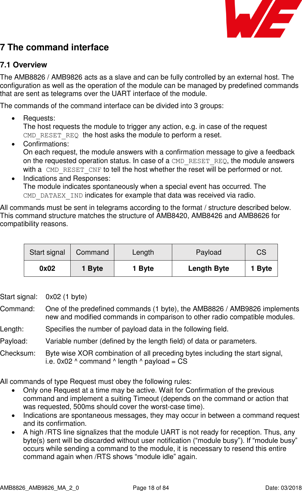
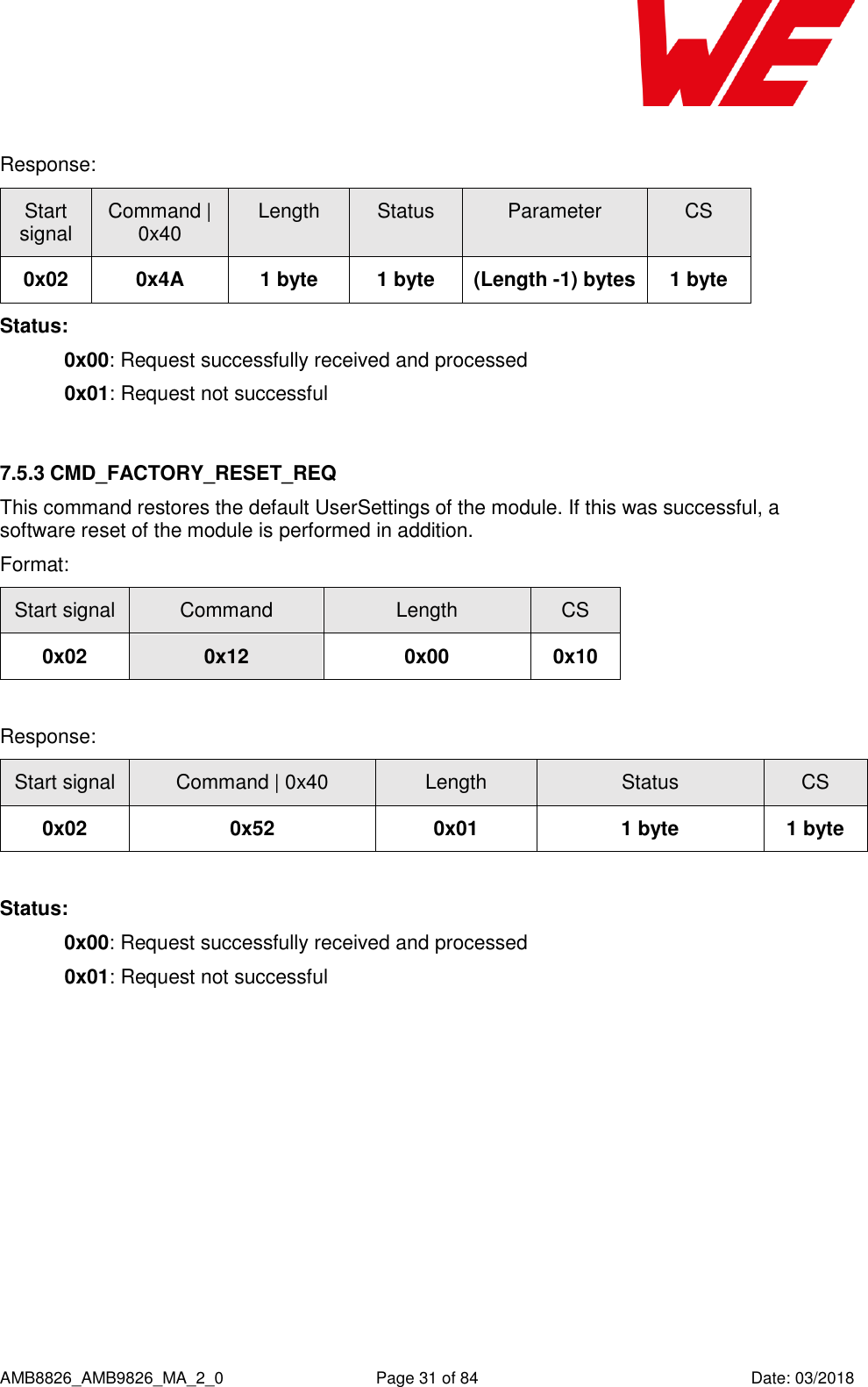
![AMB8826_AMB9826_MA_2_0 Page 14 of 84 Date: 03/2018 5 Functional description The AMB8826/AMB9826 can be configured to operate in several modes at the physical, MAC as well as the network layer. This chapter describes all the available modes of operation. 5.1 Physical layer At the physical layer, the AMB8826/AMB9826 can be configured to use one of the following radio profiles (see parameter RADIO_DefaultRfProfile). Radio profiles 3,4 are optimized to provide long range transmission whereas profiles 5,6 enable higher data rates. Radio profile Data rate (gross) [kcps] Modulation Max packet size [bytes] AMB8826: 0 38.4 FSK 128 2 100 FSK 128 3 (long range mode) 10 (=0.625 kbps net) FSK (with FEC) 48 4 (long range mode) 20 (=2.5 kbps net) FSK (with FEC) 64 5 400 GFSK 224 AMB9826: 6 400 GFSK 224 Additionally, the frequency channel of operation is configurable to avoid interference between several subnets of radio devices (see parameter RADIO_DefaultRfChannel). The radio parameters need to be chosen for optimal performance based on the required range, data rate, maximum payload size, keeping in mind the compliance with valid regulatory requirements. A detailed description for configuring these parameters could be found in chapter 8 and chapter 9. 5.2 MAC and network layer 5.2.1 Addressing modes In order to interconnect several modules and build a network or to send data to specific devices, the AMB8826 / AMB9826 supports addressing at MAC and network levels. Based on the address mode of the module configured using the UserSetting MAC_DefaultAddressMode, each device can be configured with an address (1 or 2 byte) and a network id (1 byte) that is defined by the UserSettings MAC_SourceAddr and MAC_SourceNetID respectively.](https://usermanual.wiki/Wuerth-Elektronik-eiSos-and-Co-KG/AMB9826/User-Guide-3860924-Page-15.png)
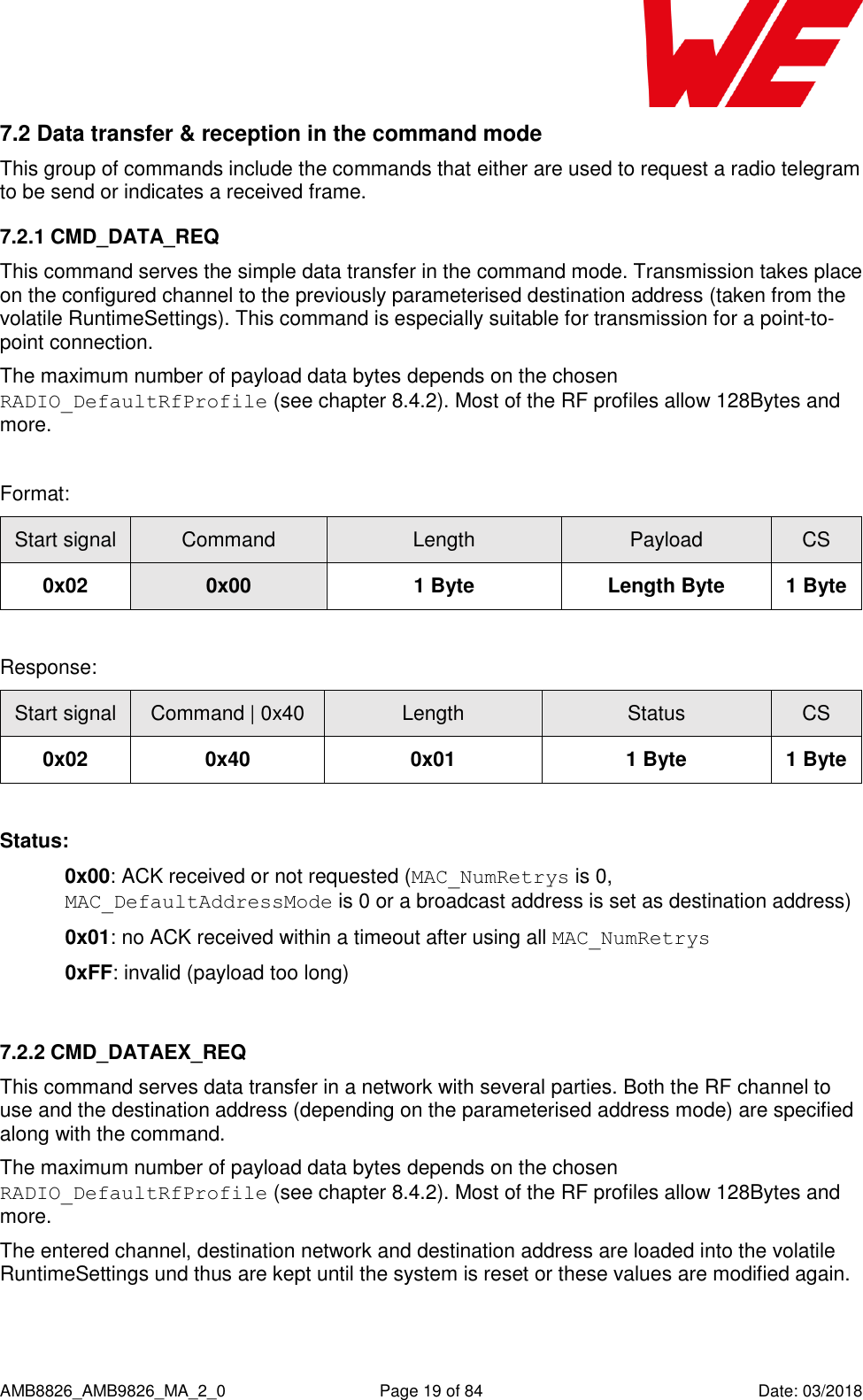
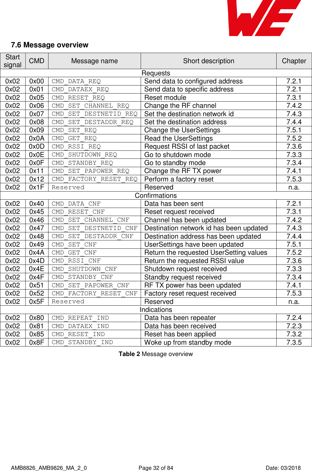
![AMB8826_AMB9826_MA_2_0 Page 15 of 84 Date: 03/2018 Address mode MAC address size [byte] Network address size [byte] 0 0 0 1 1 0 2 1 1 3 2 1 Depending on the selected address mode up to 254 network IDs and up to 65534 addresses are supported. Please note that the RF settings (e.g. RF profile, RF channel, address mode, repeater settings) must be the same for all nodes in the network. Violation may cause interrupted transmission, or received packets that cannot to be interpreted correctly. In addition, the timing parameters in case of repeater or enabled ACKs must be the same for all nodes in a network. The address mode 3 (254 network ids and 65534 addresses) is only supported by the AMB8626 and AMB8826 / AMB9826. Radio messages of devices that are using the same radio channel may interfere with each other leading to possible collisions and packet loss. 5.2.2 Unicast A module can use the command CMD_DATA_REQ to send data to a pre-defined destination specified by the parameters MAC_DefaultDestAddr and MAC_DefaultDestNetID. Besides this, the command CMD_DATAEX_REQ triggers the data transmission to the address specified in the command (refer section 7.2.1). 5.2.3 Multicast/Broadcast The destination address or destination network id of 0xFF (255) or 0xFFFF (65535) stands for a broadcast which will trigger any compatible receiver to interpret this frame to forward it to its host.](https://usermanual.wiki/Wuerth-Elektronik-eiSos-and-Co-KG/AMB9826/User-Guide-3860924-Page-16.png)

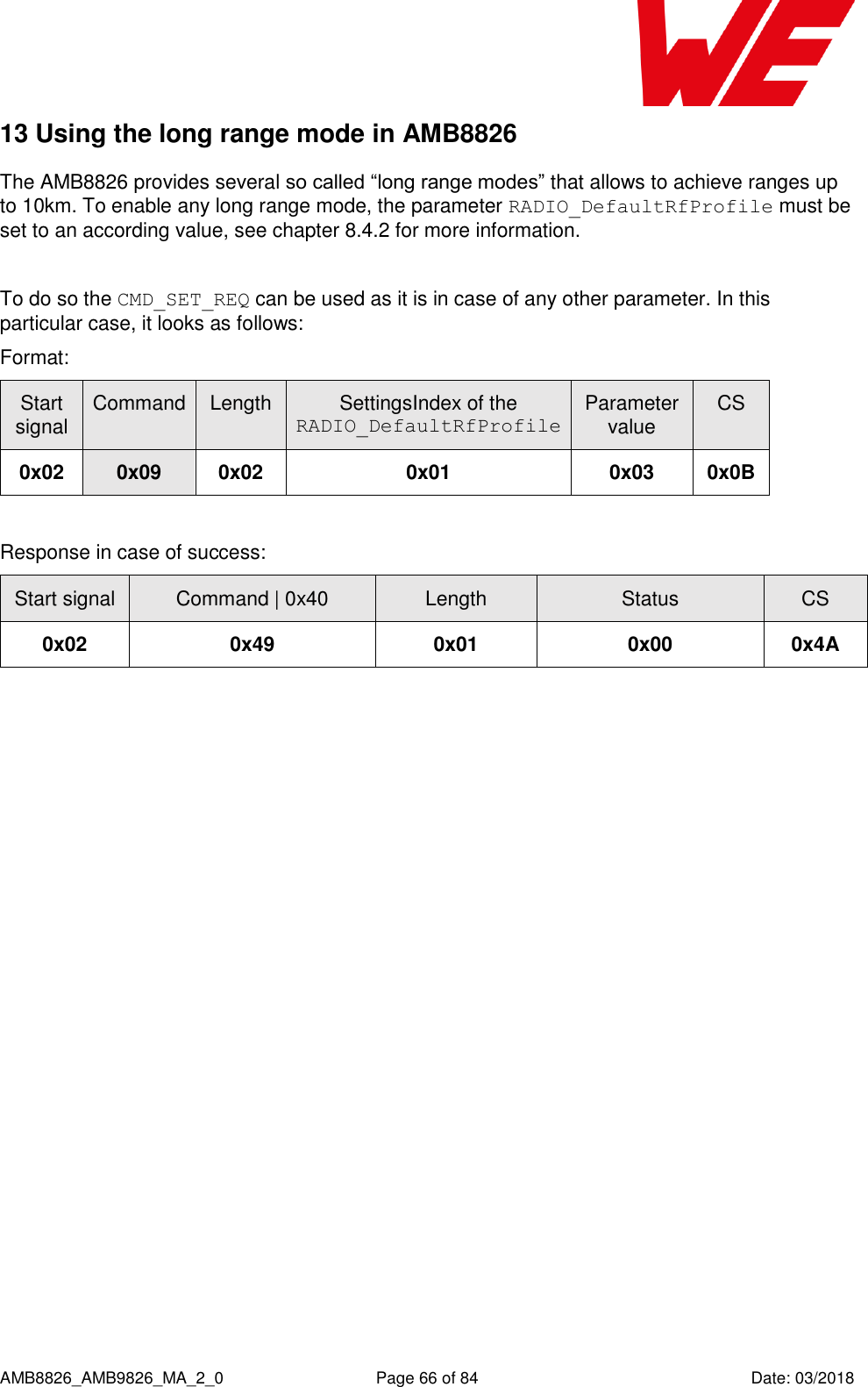
![AMB8826_AMB9826_MA_2_0 Page 35 of 84 Date: 03/2018 The UserSetting RADIO_DefaultRfProfile is an 8 bit field that addresses the applied RF configuration. Caution: The parameter must be chosen with prudence to reach good functionality and compliance with valid regulatory requirements as the EN 300 220 in the European Union or the FCC in the United States of America. After modification of the RADIO_DefaultRfProfile, please check whether the RADIO_DefaultRfChannel has to be updated too. Therefore, please refer to chapter 9. RADIO_ DefaultRfProfile Data rate (gross) [kcps] Modulation Max packet time for repeater mode [ms] Max packet size [bytes] AMB8826: 0 38.4 FSK 40 128 2 100 FSK 20 128 3 (long range mode) 10 (=0.625 kbps net) FSK (with FEC) 1000 48 4 (long range mode) 20 (=2.5 kbps net) FSK (with FEC) 300 64 5 400 GFSK 10 224 AMB9826: 6 400 GFSK 10 224](https://usermanual.wiki/Wuerth-Elektronik-eiSos-and-Co-KG/AMB9826/User-Guide-3860924-Page-36.png)
![AMB8826_AMB9826_MA_2_0 Page 53 of 84 Date: 03/2018 8.3 Settings overview SettingsIndex Designation Summary Permissible values Default value Permissions Number of bytes 0 UART_Baudrate Baud rate of the UART [baud] 9600 – 921600 115200 read/write 4 1 RADIO_DefaultRfProfile RF-settings of the module AMB8826: 0, 2, 3, 4, 5 AMB8826: 0 read/write 1 AMB9826: 6 AMB9826: 6 2 RADIO_DefaultRfTXPower TX-power of the module [dBm] 0 – 14 14 read/write 1 3 RADIO_DefaultRfChannel RF-channel of the module AMB8826: 100 – 140 AMB8826: 106 read/write 1 AMB9826: 201 – 251 AMB9826: 226 4 MAC_DefaultAddressMode Mode used to device addressing 0 – 3 0 read/write 1 6 MAC_NumRetrys Number of wireless retries 0 – 255 0 read/write 1 7 MAC_DefaultDestNetID Default destination address 0 – 255 255 read/write 1 8 MAC_DefaultDestAddr Default destination network ID 0 – 65535 65535 read/write 1-2 10 MAC_SourceNetID Own network id 0 – 254 0 read/write 1 11 MAC_SourceAddr Own address 0 – 65534 0 read/write 1-2](https://usermanual.wiki/Wuerth-Elektronik-eiSos-and-Co-KG/AMB9826/User-Guide-3860924-Page-54.png)
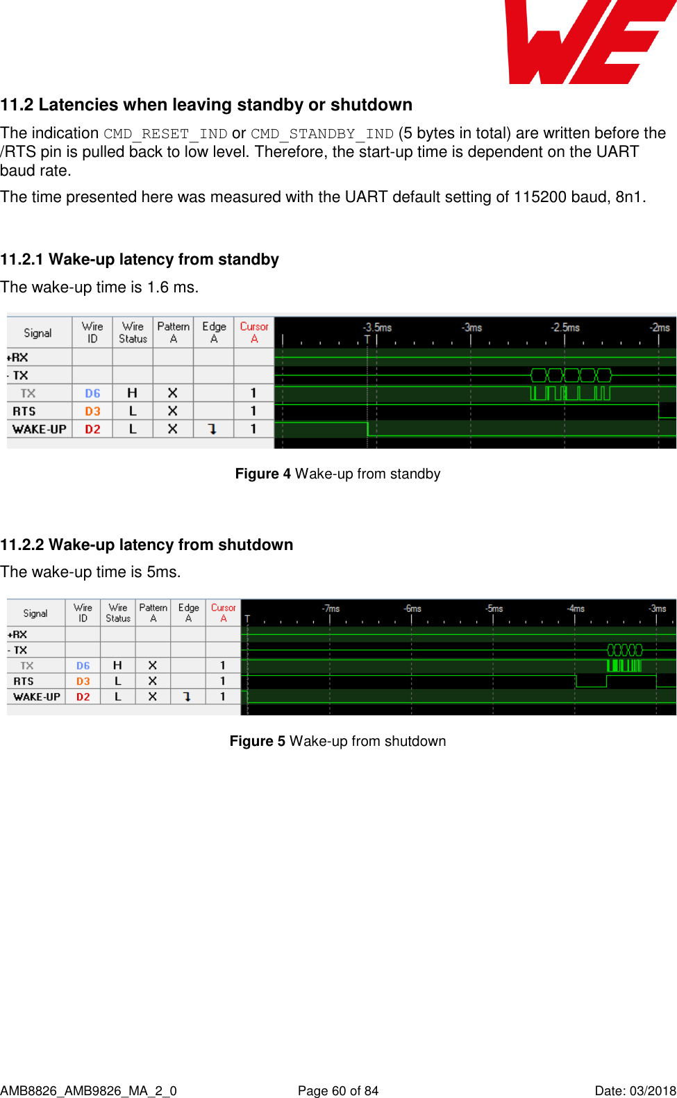
![AMB8826_AMB9826_MA_2_0 Page 58 of 84 Date: 03/2018 10 Battery powered operation For battery-powered operation, the AMB8826 / AMB9826 provides two sleep modes. Each mode can be entered by a specific command and left by applying a falling edge at the wake-up pin. Shutdown Standby Enter mode By command CMD_SHUTDOWN_REQ By command CMD_STANDBY_REQ Typical current consumption [µA] 0.1 1.6 Wake-up trigger Falling edge at the wake-up pin CPU wake-up time [ms] see chapter 11.2. see chapter 11.2. Wake-up behaviour The module restarts such that all volatile settings are lost. RAM is retained and module just continues its operation Wake-up message CMD_RESET_IND message (0x02 0x85 0x01 0x10 0x96) CMD_STANDBY_IND message (0x02 0x8F 0x01 0x00 0x8C)](https://usermanual.wiki/Wuerth-Elektronik-eiSos-and-Co-KG/AMB9826/User-Guide-3860924-Page-59.png)

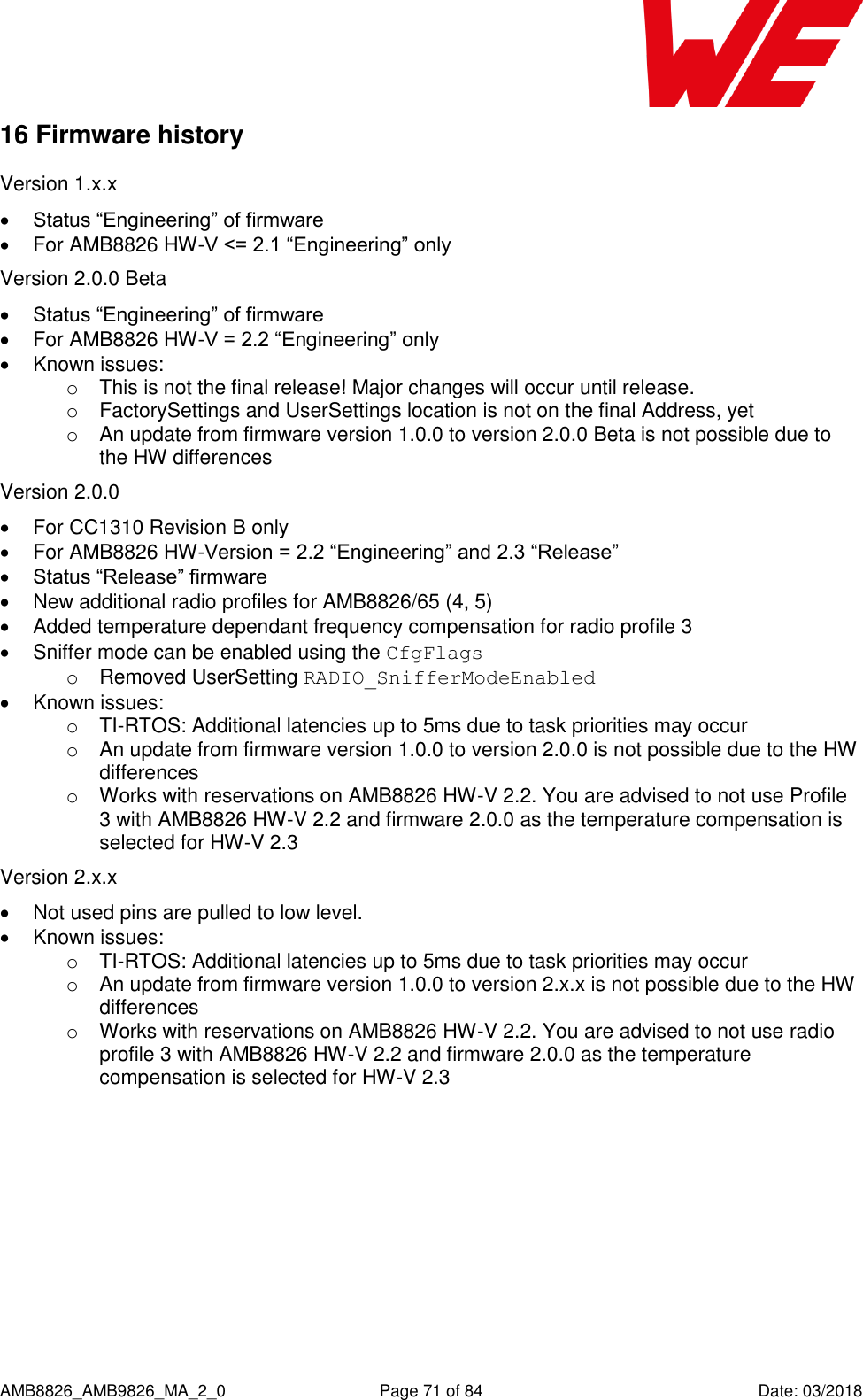
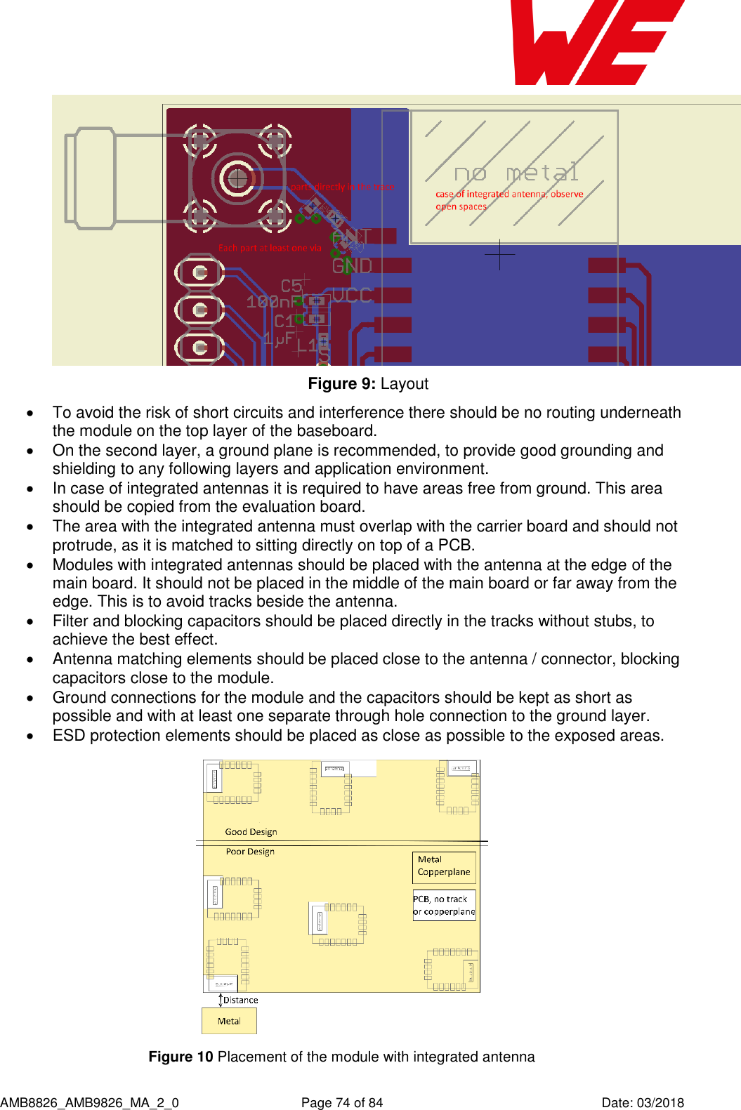
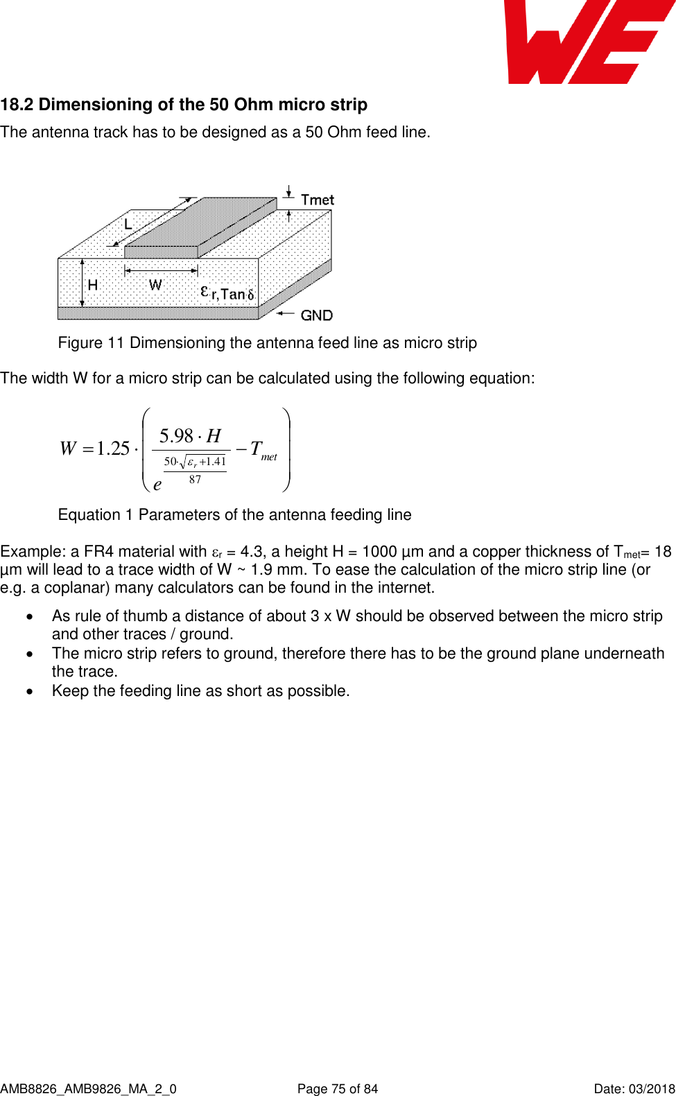
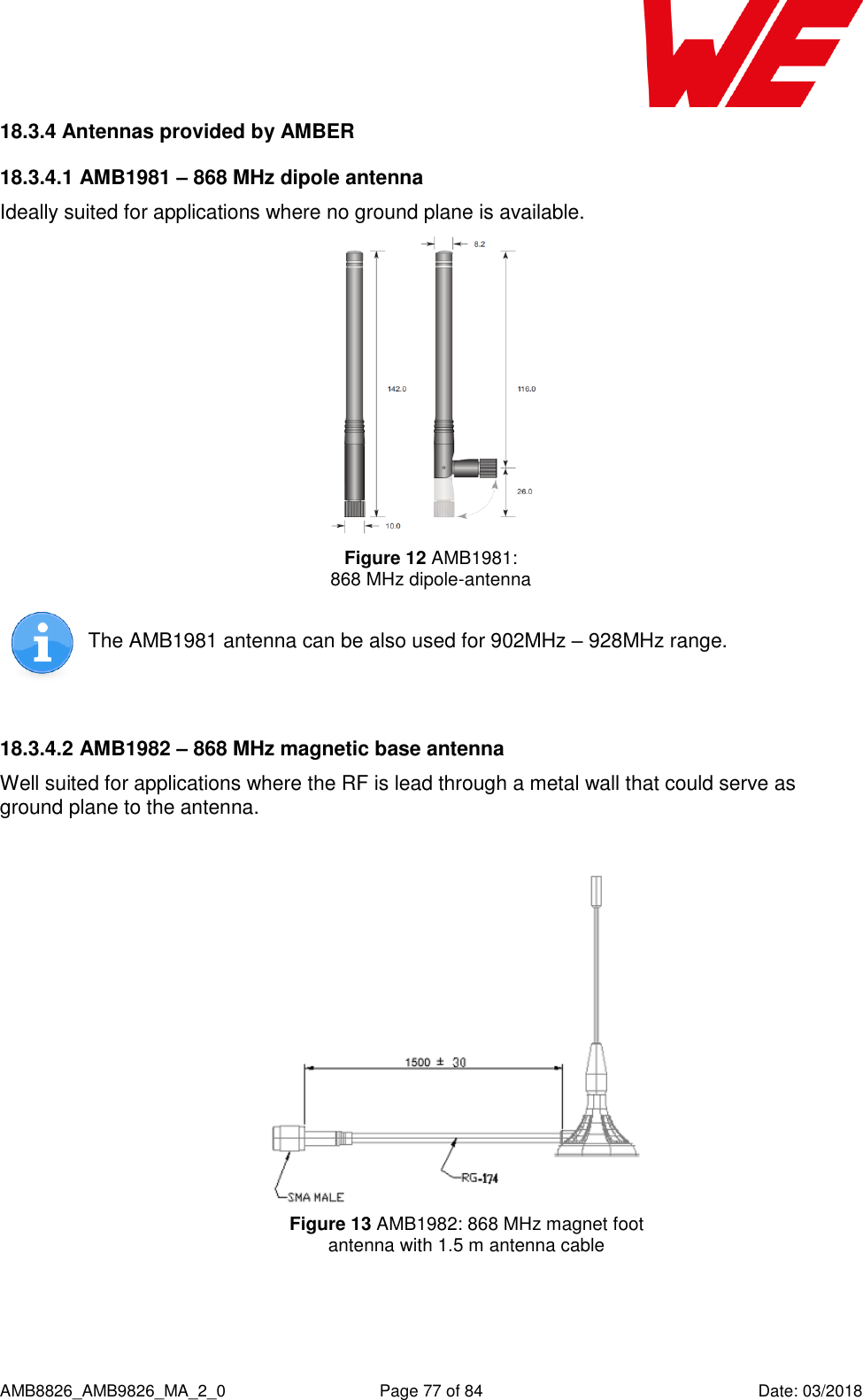
![AMB8826_AMB9826_MA_2_0 Page 72 of 84 Date: 03/2018 17 Hardware integration 17.1 Footprint and dimensions Figure 8: Footprint and dimensions for the AMB8826 / AMB9826, [mm] The following points have to be considered: To avoid the risk of short circuits, a minimum clearance of at least 14 mm between the opposing pad rows has to be maintained! No Routing on the top layer of a carrier PCB (i.e. “under” the module) shall be performed. For the AMB8826 / AMB9826 variant with integrated antenna the marked corner area of 7.3 x 13.8 mm has to be kept free from metal, on any layer. The four bottom side pads are optionally for the firmware update using JTAG can be left open when JTAG update is not needed in the customer’s application. This footprint is also compatible to AMB8626, AMB8426, AMB4426 and AMB3626.](https://usermanual.wiki/Wuerth-Elektronik-eiSos-and-Co-KG/AMB9826/User-Guide-3860924-Page-73.png)
![AMB8826_AMB9826_MA_2_0 Page 80 of 84 Date: 03/2018 20 References [1] „CC1310 SimpleLink™ Ultralow Power Sub-1-GHz Wireless MCU”, Texas Instruments [2] “CC13xx, CC26xx SimpleLink Wireless MCU Technical Reference Manual”, Texas Instruments [3] „CC1310 SimpleLink Wireless MCU Silicon Errata“, Texas Instruments [4] „AMB8826 Datasheet”, AMBER wireless GmbH [5] “AMB8926 Datasheet”, AMBER wireless GmbH](https://usermanual.wiki/Wuerth-Elektronik-eiSos-and-Co-KG/AMB9826/User-Guide-3860924-Page-81.png)