Wuerth Elektronik eiSos and Co KG AMB9826 AMB9826 User Manual Testreport ETS 300 335
Wuerth Elektronik eiSos GmbH & Co KG AMB9826 Testreport ETS 300 335
Users Manual

Test report no. 18011299 Page 1 of 1
EUT: 2609011091001,
2609011191001
FCC ID: R7TAMB9826
FCC Title 47 CFR Part 15
Date of issue: 2018-05-08
Date: 2017-09-07
Created: P9 Controlled: P4 Released: P1
Vers. no. 1.17
m. dudde hochfrequenz-technik
GmbH & Co. KG
Rottland 5a
51429 Bergisch Gladbach/ Germany
Tel: +49 2207-96890
Fax +49 2207-968920
Annex acc. to FCC Title 47 CFR Part 15
relating to
Würth Elektronik eiSos GmbH & Co. KG
2609011091001, 2609011191001
Annex no. 5
User Manual
Functional Description
Title 47 - Telecommunication
Part 15 - Radio Frequency Devices
Subpart C – Intentional Radiators
ANSI C63.4-2014
ANSI C63.10-2013


AMB8826_AMB9826_MA_2_0 Page 2 of 84 Date: 03/2018
Table of Contents
1 Introduction ........................................................................................................................... 6
2 Physical parameters .............................................................................................................. 7
2.1 Dimensions and weight ..................................................................................................... 7
2.2 Electrical parameters ........................................................................................................ 7
2.2.1 Absolute maximum ratings ......................................................................................... 7
2.2.2 Recommended operating conditions .......................................................................... 7
2.2.3 Power consumption .................................................................................................... 8
3 Pinout ..................................................................................................................................... 9
4 Start-up and minimal configuration ................................................................................... 11
4.1 Minimal configuration ...................................................................................................... 11
4.2 Power up ........................................................................................................................ 11
4.3 Sending & receiving: “Hello World” ................................................................................. 12
5 Functional description ........................................................................................................ 14
5.1 Physical layer .................................................................................................................. 14
5.2 MAC and network layer ................................................................................................... 14
5.2.1 Addressing modes .................................................................................................... 14
5.2.2 Unicast ..................................................................................................................... 15
5.2.3 Multicast/Broadcast .................................................................................................. 15
5.2.4 Acknowledgement and retries .................................................................................. 16
5.2.5 Packet sniffer mode .................................................................................................. 16
5.2.6 Repeater mode and mesh network ........................................................................... 16
5.3 System configuration parameters .................................................................................... 16
6 Host connection: Serial interface ....................................................................................... 17
6.1 UART .............................................................................................................................. 17
7 The command interface ...................................................................................................... 18
7.1 Overview ......................................................................................................................... 18
7.2 Data transfer & reception in the command mode ............................................................ 19
7.2.1 CMD_DATA_REQ .................................................................................................... 19
7.2.2 CMD_DATAEX_REQ ............................................................................................... 19
7.2.3 CMD_DATAEX_IND ................................................................................................. 21
7.2.4 CMD_REPEAT_IND ................................................................................................. 23
7.3 Requesting parameters, actions and events ................................................................... 24
7.3.1 CMD_RESET_REQ .................................................................................................. 24
7.3.2 CMD_RESET_IND ................................................................................................... 24
7.3.3 CMD_SHUTDOWN_REQ......................................................................................... 24
7.3.4 CMD_STANDBY_REQ ............................................................................................. 25
7.3.5 CMD_STANDBY_IND .............................................................................................. 26
7.3.6 CMD_RSSI_REQ ..................................................................................................... 26
7.4 Modification of volatile parameters .................................................................................. 27
7.4.1 CMD_SET_PAPOWER_REQ .................................................................................. 27
7.4.2 CMD_SET_CHANNEL_REQ .................................................................................... 27
7.4.3 CMD_SET_DESTNETID_REQ ................................................................................ 28
7.4.4 CMD_SET_DESTADDR_REQ ................................................................................. 29
7.5 Modification of non-volatile parameters ........................................................................... 29
7.5.1 CMD_SET_REQ ...................................................................................................... 29
7.5.2 CMD_GET_REQ ...................................................................................................... 30
7.5.3 CMD_FACTORY_RESET_REQ ............................................................................... 31
7.6 Message overview .......................................................................................................... 32

AMB8826_AMB9826_MA_2_0 Page 3 of 84 Date: 03/2018
8 UserSettings – AMB8826 / AMB9826 configuration values .............................................. 33
8.1 Difference between volatile and non-volatile settings ...................................................... 33
8.2 Modifying the UserSettings ............................................................................................. 33
8.2.1 UART_Baudrate: Configure the UART speed ........................................................... 33
8.2.2 RADIO_DefaultRfProfile: Configure the RF-settings ................................................. 34
8.2.3 RADIO_DefaultRfTXPower: Configure the RF TX-power ......................................... 37
8.2.4 RADIO_DefaultRfChannel: Configure the RF channel .............................................. 38
8.2.5 MAC_DefaultAddressMode: Configure the address mode ........................................ 39
8.2.6 MAC_NumRetrys: Configure the number of retries ................................................... 40
8.2.7 MAC_DefaultDestNetID: Configure the destination network id ................................. 42
8.2.8 MAC_DefaultDestAddr: Configure the destination address ....................................... 43
8.2.9 MAC_SourceNetID: Configure the source network id ............................................... 44
8.2.10 MAC_SourceAddr: Configure the source address .................................................. 45
8.2.11 OpMode: Read the operating mode of the module ................................................. 46
8.2.12 CfgFlags: Configure the configuration flags of the module ...................................... 47
8.2.13 RpFlags: Configure the repeater flags of the module .............................................. 48
8.2.14 RP_NumSlots: Configure the repeater data base ................................................... 49
8.2.15 FactorySettings: Read out the factory settings ........................................................ 51
8.2.16 FirmwareVersion: Read out the firmware version ................................................... 52
8.3 Settings overview ............................................................................................................ 53
9 Radio parameters ................................................................................................................ 55
9.1 AMB8826 ........................................................................................................................ 55
9.1.1 AMB8826 Channel assignment ................................................................................ 56
9.2 AMB9826 ........................................................................................................................ 57
9.2.1 AMB9826 Channel assignment ................................................................................ 57
10 Battery powered operation ............................................................................................... 58
11 Timing parameters ............................................................................................................ 59
11.1 Reset behaviour ............................................................................................................ 59
11.1.1 Reset via /RESET pin ............................................................................................. 59
11.1.2 Reset as result of a serious error condition ............................................................. 59
11.2 Latencies when leaving standby or shutdown ............................................................... 60
11.2.1 Wake-up latency from standby ............................................................................... 60
11.2.2 Wake-up latency from shutdown ............................................................................. 60
11.3 Latencies during data transfer / packet generation ........................................................ 61
12 Flooding mesh: Using the repeater functionality ............................................................ 62
12.1.1 Setup of the network and repeater device .............................................................. 63
12.1.2 Example network .................................................................................................... 64
12.1.3 Application in parallel networks............................................................................... 65
13 Using the long range mode in AMB8826 ......................................................................... 66
14 Firmware update ................................................................................................................ 67
14.1 Update using UART0 interface ...................................................................................... 67
14.2 Update using JTAG ....................................................................................................... 68
15 AMB8826 compatibility to existing proprietary modules ................................................ 69
15.1 Restrictions ................................................................................................................... 70
16 Firmware history ............................................................................................................... 71
17 Hardware integration ......................................................................................................... 72
17.1 Footprint and dimensions .............................................................................................. 72
18 Design in guide .................................................................................................................. 73

AMB8826_AMB9826_MA_2_0 Page 4 of 84 Date: 03/2018
18.1 Advice for schematic and layout .................................................................................... 73
18.2 Dimensioning of the 50 Ohm micro strip ....................................................................... 75
18.3 Antenna solutions ......................................................................................................... 76
18.3.1 Lambda/4 radiator .................................................................................................. 76
18.3.2 Chip antenna .......................................................................................................... 76
18.3.3 PCB antenna .......................................................................................................... 76
18.3.4 Antennas provided by AMBER ............................................................................... 77
19 Manufacturing information ............................................................................................... 79
20 References ......................................................................................................................... 80
21 Regulatory compliance information ................................................................................. 81
21.1 Important notice ............................................................................................................ 81
21.1.1 FCC Compliance statement AMB9826 & AMB9826-1 ............................................ 82
21.1.2 IC Compliance statement AMB9826 & AMB9826-1 ................................................ 82
21.1.3 FCC and IC Requirements to OEM integrators ....................................................... 82
21.1.4 AMB9826 & AMB9826-1......................................................................................... 83
22 Important information ....................................................................................................... 84
22.1 Exclusion of liability ....................................................................................................... 84
22.2 Trademarks ................................................................................................................... 84
22.3 Usage restriction ........................................................................................................... 84

AMB8826_AMB9826_MA_2_0 Page 5 of 84 Date: 03/2018
Abbreviations and abstract
ACK
Acknowledgement
Acknowledgement pattern confirming the reception of the
transmitted data packet
CS
Checksum
DC
Duty cycle
Relative frequency reservation period
LPM
Low power mode
Operation mode for reduced power consumption.
RF
Radio frequency
Describes everything relating to the wireless transmission
Payload
The real, non-redundant information in a frame/packet
UserSettings
Any relation to a specific entry in the UserSettings is
marked in a special font and can be found in the respective
chapter
UART
Universal Asynchronous Receiver Transmitter allows
communicating with the module of a specific interface.
Duty cycle
Transmission time in relation of one hour
1% means, channel is occupied for 36 seconds per hour.
Hexadecimal
[HEX]
0xhh
All numbers beginning with 0x are stated as hexadecimal
numbers. All other numbers are decimal.

AMB8826_AMB9826_MA_2_0 Page 6 of 84 Date: 03/2018
1 Introduction
The AMB8826 / AMB9826 module is a radio sub module for wireless communication between
devices such as control systems, remote controls, sensors etc. It offers several radio
configurations, address modes and relieves the host system of radio-specific tasks as
checksum calculation,
address resolution
repetition of unacknowledged telegrams (if enabled)
It can be deployed wherever the wireless exchange of data packets (up to 224 bytes user data)
between two or more parties is required.
A serial interface (UART) whose data rate and format can be adjusted flexibly is available for
communicating with the host system.

AMB8826_AMB9826_MA_2_0 Page 7 of 84 Date: 03/2018
2 Physical parameters
2.1 Dimensions and weight
Dimensions
17 x 27 x 4 mm
Weight
3g
2.2 Electrical parameters
As not otherwise stated measured on AMB8826-EV / AMB9826-EV with T=25°C, VDDS=3V,
internal DC-DC converter in use. Radio transmission uses boost mode independent of the
chosen output power.
2.2.1 Absolute maximum ratings
Description
min
typ
max
unit
Supply voltage (VDDS)
-0.3
4.1
V
Voltage on any digital pin
-0.3
VDDS + 0.3,
max 4.1
V
Input RF level
10
dBm
Output RF level, with boost mode
14
dBm
2.2.2 Recommended operating conditions
Description
min
typ
max
unit
Ambient temperature
-40
85
°C
Supply voltage (VDDS)
2.21
3.8
V
Rising supply voltage slew rate
0
100
mV/µs
Falling supply voltage slew rate
0
20
mV/µs
Falling supply voltage slew rate, with low power flash settings
3
mV/µs
1
When the whole temperature range is used, a minimum voltage of 2.4V is recommended.
AMB8826_AMB9826_MA_2_0 Page 8 of 84 Date: 03/2018
2.2.3 Power consumption
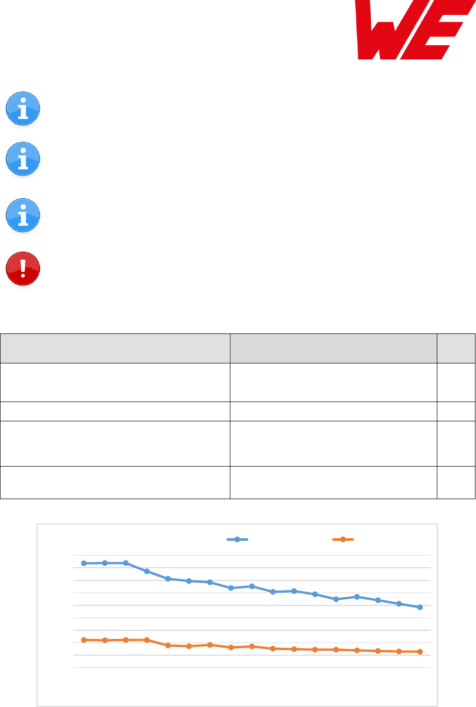
As a DC/DC voltage regulator is integrated, the current consumption is strongly
depending on the supplied voltage level.
The Transmit and Receive Currents are depending on the impedance matching, and
therefore may vary depending on antenna selection and matching.
The indicated values are the complete current consumption for radio and active
MCU. Not to be confused with only radio or only cpu core currents, as sometimes
stated by others.
A stable supply indispensable to ensure valid operating conditions for the module.
VDDS = 3.6V, transmit current in boost mode
Description
typ
unit
TX current 10 dBm output power
TX current 14 dBm output power
17
26
mA
RX current
8
mA
Low Power (standby)
radio off, uart off, rtc running, full RAM
retention
1.0
µA
Low Power (shutdown)
radio off, uart off, rtc off, no RAM retention
0.2
µA
Figure 1: Typical behavior of transmit and receive current in relation to applied supply voltage
0
5
10
15
20
25
30
35
40
45
2,2 2,3 2,4 2,5 2,6 2,7 2,8 2,9 3 3,1 3,2 3,3 3,4 3,5 3,6 3,7 3,8
Current [mA]
Voltage [V]
Transmit Current Receive Current
AMB8826_AMB9826_MA_2_0 Page 9 of 84 Date: 03/2018
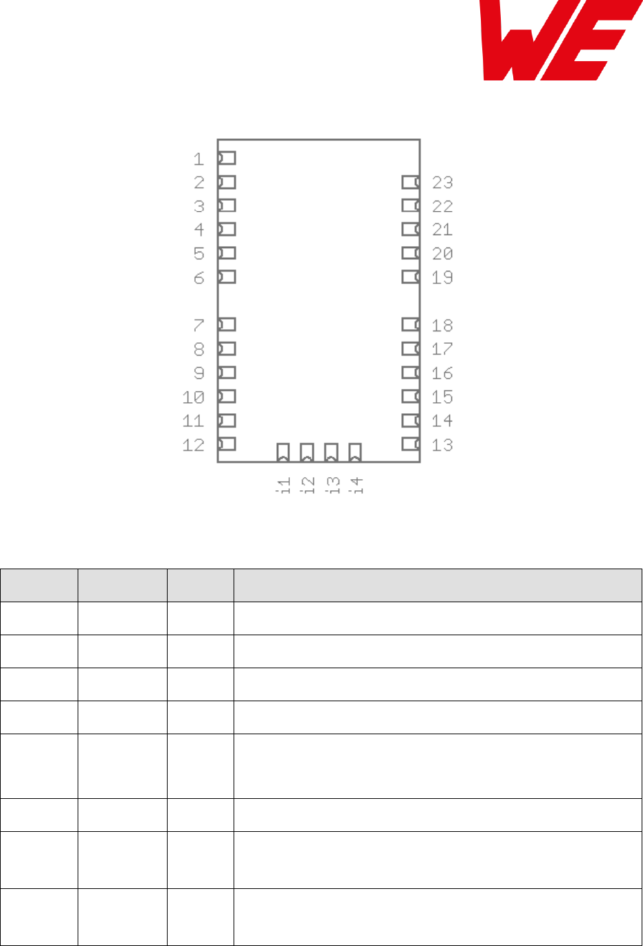
3 Pinout
Figure 2 Pinout (Top view)
No
Designation
I/O
Description
1
ANT
I/O
Antenna connection
2, 23
GND
Supply
Ground
3
VCC
Supply
Supply voltage
4
UTXD
Output
UART (Transmission), bootloader TX
5
URXD
Input
UART (Reception), bootloader RX,
App: Uses an internal pull-up.
Bootloader: Uses an internal pull-up
6
/RTS
Output
Indicates that the module is busy, busy = high level.
7
Reserved
(/CTS)
I/O
Reserved for future use.
Uses an internal pull-up. Do not connect.
8, 9, 10,
11
Reserved
I/O
Reserved for future use.
Uses an internal pull-down. Do not connect.

AMB8826_AMB9826_MA_2_0 Page 10 of 84 Date: 03/2018
No
Designation
I/O
Description
12
BOOT
Input
Apply a low-level signal during and shortly after reset to start the
application firmware. Apply a high level to enable the CC13x0
bootloader, which is necessary for ACC Connection,
configuration and firmware updates.
Connect to GND if ACC and firmware update function is not
needed (e.g. 1kΩ pull-down).
13
Reserved
I/O
Reserved for future use. Uses an internal pull-down. Do not
connect.
14
WAKE-UP
Input
Apply a falling edge to wake-up from shutdown or standby mode.
Uses an internal pull-down. Do not connect if not needed.
15, 16, 17,
18
Reserved
I/O
Reserved for future use. Uses an internal pull-down. Do not
connect.
19
/RESET
Input
Apply a falling edge to reset the module. Pin has internal Pull-up
of 100kΩ.
Low level holds module in reset state.
20
RX_IND
Output
Indicates RF data reception, active = high
Do not connect if not needed.
21
TX_IND
Output
Indicates RF data transmission, active = high
Do not connect if not needed.
22
Reserved
I/O
Reserved for future use. Uses an internal pull-down. Do not
connect.
i1
JTAG TMS
Input
Debug interface
Do not connect if not needed.
i2
JTAG TCK
Input
Debug interface
Do not connect if not needed.
i3
JTAG TDO
Input
Debug interface
Do not connect if not needed.
i4
JTAG TDI
Input
Debug interface
Do not connect if not needed.
Table 1 Pinout

AMB8826_AMB9826_MA_2_0 Page 11 of 84 Date: 03/2018
4 Start-up and minimal configuration
4.1 Minimal configuration
In factory state, the module is immediately ready for operation in command mode. The following
pins are required in the minimal configuration:
/RESET, BOOT, VCC, GND, /RTS, UTXD and URXD.
If the module is connected to a PC, a converter (TTL to RS-232 or TTL to USB) is necessary to
achieve interface compatibility. The AMB8826-EV / AMB9826-EV already implements such a
USB converter to be connected to a PC.
Not interpreting the /RTS line of the module as described in this manual may cause undefined
behaviour.
For enabling a quick WAKE-UP (after Standby) the pin “wake-up” has to be connected.
The lines BOOT and WAKE-UP may be connected via external pull-up / down to a fixed level
according to their description when not switched by a host.
In case of the WAKE-UP pin the external pull-up has to be selected accordingly in comparison
with the internal resistor of typical 13kΩ.
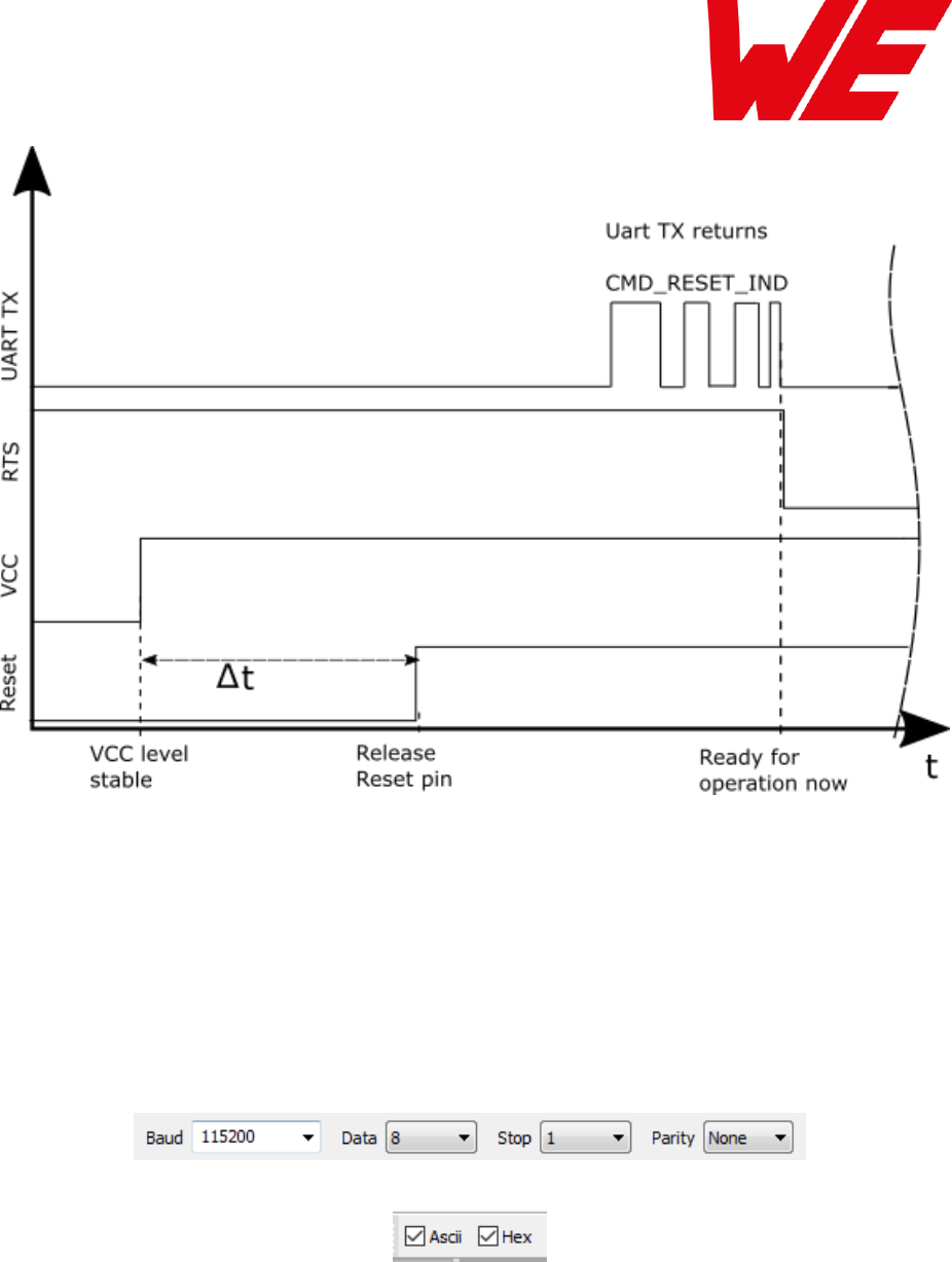
4.2 Power up
Recommended procedure for starting the module into normal operation:
Set and hold the BOOT pin to LOW. After supply voltage is applied to the module, the /RESET
pin shall be hold to LOW level for another Δt of at least 1ms after the VCC is stable to ensure a
safe start-up. The module will send a CMD_RESET_IND message as well as showing a low level
of the /RTS line once it is booted into application.
Then the Boot pin may be released or kept at LOW level.
If the module is used on a battery-powered system, using a matching Reset-IC is highly
recommended to ensure a correct power up and stable behaviour towards battery getting
empty.
AMB8826_AMB9826_MA_2_0 Page 12 of 84 Date: 03/2018
Figure 3 Power up timing
4.3 Sending & receiving: “Hello World”
Connect the two devices (modules, EV-boards or USB dongles) to a PC. A minimum distance of
2 meters between the devices should be kept to avoid over modulation of the receiver.
A terminal program, for example hterm, is used to perform the communication via COM ports.
The two corresponding COM ports have to be selected and opened with a default configuration
of 115200 baud, 8 Data bits, 1 Stop bit and Parity set to none (8n1).
Make sure the received data is shown also as hex by enabling the corresponding checkbox:
As soon as the module is ready for operation (at start-up or after a reset), the device sends a
CMD_RESET_IND message (0x02 0x85 0x01 0x10 0x96) on the UART. Eventually the reset
button has to be pushed (or CMD_RESET_REQ performed) to trigger a reset and see this
message.
Next, the command interface can be used to configure the module or to transmit data. The
MAC_DefaultAddressMode is “0”, which means that all radio frames are broadcasts that can
be received by any other radio compatible device in default settings.
AMB8826_AMB9826_MA_2_0 Page 13 of 84 Date: 03/2018
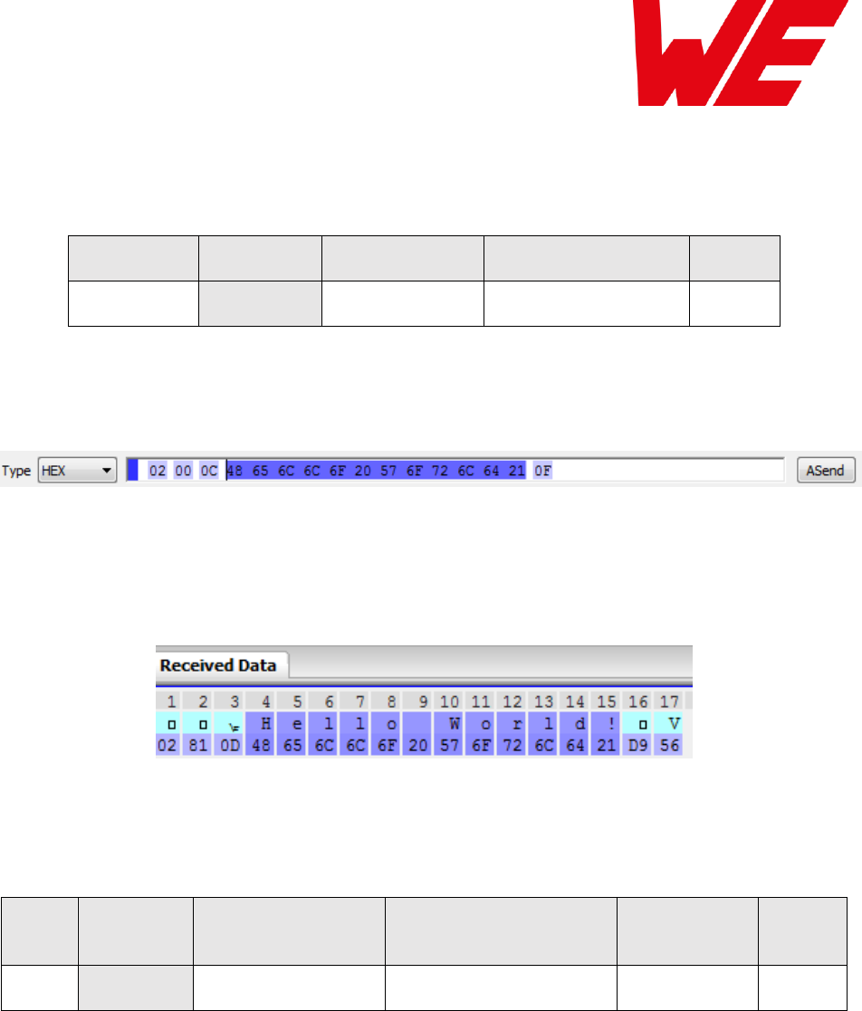
To send the string “Hello World” the corresponding CMD_DATA_REQ has to be inserted into the
input line of hterm. The “Type” needs to be change from “ASC” to “HEX” before entering the first
byte. The command CMD_DATA_REQ has the following structure:
Start signal
Command
Length
Payload
CS
0x02
0x00
1 Byte
Length Byte
1 Byte
In this example the payload 0x48 0x65 0x6C 0x6C 0x6F 0x20 0x57 0x6F 0x72 0x6C 0x64 0x21
(Hello World!) has a length of 12 (0x0C) bytes. The checksum CS is a XOR conjunction of all
previous bytes, which is 0x0F in this case.
Using the “ASend” button followed by pushing the “start” button sends the data once. The
second module receiving this packet outputs a CMD_DATAEX_IND message containing the
transmitted payload data and the corresponding RSSI value.
In the default address mode (MAC_DefaultAddressMode = 0), the format of the
CMD_DATAEX_IND is as follows:
Start
signal
Command
Length
Payload
RSSI
CS
0x02
0x81
1 Byte
(Length - 1) bytes
1 byte
1 byte
Thus, the CMD_DATAEX_IND message informs us that we received a packet with payload of 13
(0x0D) bytes.
12 byte of these bytes are the transmitted user payload 0x48 0x65 0x6C 0x6C 0x6F 0x20 0x57
0x6F 0x72 0x6C 0x64 0x21 (Hello World!) and one byte is the RSSI value, here 0xD9 (-39dBm
in two’s complement notation).

AMB8826_AMB9826_MA_2_0 Page 14 of 84 Date: 03/2018
5 Functional description
The AMB8826/AMB9826 can be configured to operate in several modes at the physical, MAC
as well as the network layer. This chapter describes all the available modes of operation.
5.1 Physical layer
At the physical layer, the AMB8826/AMB9826 can be configured to use one of the following
radio profiles (see parameter RADIO_DefaultRfProfile). Radio profiles 3,4 are optimized to
provide long range transmission whereas profiles 5,6 enable higher data rates.
Radio profile
Data rate (gross)
[kcps]
Modulation
Max packet size
[bytes]
AMB8826:
0
38.4
FSK
128
2
100
FSK
128
3
(long range mode)
10
(=0.625 kbps net)
FSK
(with FEC)
48
4
(long range mode)
20
(=2.5 kbps net)
FSK
(with FEC)
64
5
400
GFSK
224
AMB9826:
6
400
GFSK
224
Additionally, the frequency channel of operation is configurable to avoid interference between
several subnets of radio devices (see parameter RADIO_DefaultRfChannel).
The radio parameters need to be chosen for optimal performance based on the required range,
data rate, maximum payload size, keeping in mind the compliance with valid regulatory
requirements.
A detailed description for configuring these parameters could be found in chapter 8 and
chapter 9.
5.2 MAC and network layer
5.2.1 Addressing modes
In order to interconnect several modules and build a network or to send data to specific devices,
the AMB8826 / AMB9826 supports addressing at MAC and network levels. Based on the
address mode of the module configured using the UserSetting MAC_DefaultAddressMode,
each device can be configured with an address (1 or 2 byte) and a network id (1 byte) that is
defined by the UserSettings MAC_SourceAddr and MAC_SourceNetID respectively.

AMB8826_AMB9826_MA_2_0 Page 15 of 84 Date: 03/2018
Address mode
MAC address
size [byte]
Network
address size
[byte]
0
0
0
1
1
0
2
1
1
3
2
1
Depending on the selected address mode up to 254 network IDs and up to 65534 addresses
are supported.
Please note that the RF settings (e.g. RF profile, RF channel, address mode,
repeater settings) must be the same for all nodes in the network.
Violation may cause interrupted transmission, or received packets that cannot to be
interpreted correctly.
In addition, the timing parameters in case of repeater or enabled ACKs must be the
same for all nodes in a network.
The address mode 3 (254 network ids and 65534 addresses) is only supported by
the AMB8626 and AMB8826 / AMB9826.
Radio messages of devices that are using the same radio channel may interfere with
each other leading to possible collisions and packet loss.
5.2.2 Unicast
A module can use the command CMD_DATA_REQ to send data to a pre-defined destination
specified by the parameters MAC_DefaultDestAddr and MAC_DefaultDestNetID.
Besides this, the command CMD_DATAEX_REQ triggers the data transmission to the address
specified in the command (refer section 7.2.1).
5.2.3 Multicast/Broadcast
The destination address or destination network id of 0xFF (255) or 0xFFFF (65535) stands for a
broadcast which will trigger any compatible receiver to interpret this frame to forward it to its
host.

AMB8826_AMB9826_MA_2_0 Page 16 of 84 Date: 03/2018
5.2.4 Acknowledgement and retries
In order to improve reliability in communication, the module can be configured to use radio
acknowledgement and retry mechanism. It can be activated using the parameter,
MAC_NumRetrys (refer section 8.2.6).
5.2.5 Packet sniffer mode
The address resolution can be disabled ("packet sniffer") by enabling the sniffer mode in the
UserSetting CfgFlags. A module in sniffer mode will accept all data packets (ignoring the
target address) and forward them to the serial interface. Furthermore, it does not send any
acknowledgement and cannot work as repeater at the same time (see section 8.2.12).
5.2.6 Repeater mode and mesh network
The AMB8826 / AMB9826 module can be run as a repeater to artificially extend the range of
sending devices in an existing network. A module configured as repeater, simply re-transmits
the received packet after a random back off time. This mode allows options to build a flooding
mesh network described in detail in chapter 12.
5.3 System configuration parameters
The parameters that determine the functionality of the module are classified into two categories.
The non-volatile UserSettings (see chapter 8) values that can be modified using the
CMD_SET_REQ command retain their values after a power reset.
Please note that each CMD_SET_REQ will consume one flash erase/write cycle,
which are limited due to the hardware (guaranteed are 100k cycles, see TI CC13x0
datasheet).
On the other hand, the volatile settings (called “RuntimeSettings”) can be accessed by explicit
commands (see chapter 7.4) and used to quickly (but temporarily) modify specific parameters
without using flash cycles. These settings are only valid until a reset is performed and shall be
used when frequent updates of settings are necessary.

AMB8826_AMB9826_MA_2_0 Page 17 of 84 Date: 03/2018
6 Host connection: Serial interface
6.1 UART
The configuration in factory state of the UART is 115200 baud with data format of 8 data bits, no
parity and 1 stop bit ("8n1"). The baud rate of the UART can be configured by means of the
UserSetting UART_Baudrate. The data format is fixed to 8n1.
The output of characters on the serial interface runs with secondary priority. For this reason,
short interruptions may occur between the outputs of individual successive bytes. The host must
not implement too strict timeouts between two bytes to be able to receive packets that have
interruptions in between. Up to four full byte durations (32 bit) delay between two successive
bytes shall be accepted by the host.
For the direction “host to module” the host must respect byte-wise the line /RTS, which will
indicate that the next byte of the packet can be received by the module. This direction also
accepts a pause of up to four full byte durations (32bit) delay between two successive bytes
before discarding received content (without user notification).

AMB8826_AMB9826_MA_2_0 Page 18 of 84 Date: 03/2018
7 The command interface
7.1 Overview
The AMB8826 / AMB9826 acts as a slave and can be fully controlled by an external host. The
configuration as well as the operation of the module can be managed by predefined commands
that are sent as telegrams over the UART interface of the module.
The commands of the command interface can be divided into 3 groups:
Requests:
The host requests the module to trigger any action, e.g. in case of the request
CMD_RESET_REQ the host asks the module to perform a reset.
Confirmations:
On each request, the module answers with a confirmation message to give a feedback
on the requested operation status. In case of a CMD_RESET_REQ, the module answers
with a CMD_RESET_CNF to tell the host whether the reset will be performed or not.
Indications and Responses:
The module indicates spontaneously when a special event has occurred. The
CMD_DATAEX_IND indicates for example that data was received via radio.
All commands must be sent in telegrams according to the format / structure described below.
This command structure matches the structure of AMB8420, AMB8426 and AMB8626 for
compatibility reasons.
Start signal
Command
Length
Payload
CS
0x02
1 Byte
1 Byte
Length Byte
1 Byte
Start signal: 0x02 (1 byte)
Command: One of the predefined commands (1 byte), the AMB8826 / AMB9826 implements
new and modified commands in comparison to other radio compatible modules.
Length: Specifies the number of payload data in the following field.
Payload: Variable number (defined by the length field) of data or parameters.
Checksum: Byte wise XOR combination of all preceding bytes including the start signal,
i.e. 0x02 ^ command ^ length ^ payload = CS
All commands of type Request must obey the following rules:
Only one Request at a time may be active. Wait for Confirmation of the previous
command and implement a suiting Timeout (depends on the command or action that
was requested, 500ms should cover the worst-case time).
Indications are spontaneous messages, they may occur in between a command request
and its confirmation.
A high /RTS line signalizes that the module UART is not ready for reception. Thus, any
byte(s) sent will be discarded without user notification (“module busy”). If “module busy”
occurs while sending a command to the module, it is necessary to resend this entire
command again when /RTS shows “module idle” again.

AMB8826_AMB9826_MA_2_0 Page 19 of 84 Date: 03/2018
7.2 Data transfer & reception in the command mode
This group of commands include the commands that either are used to request a radio telegram
to be send or indicates a received frame.
7.2.1 CMD_DATA_REQ
This command serves the simple data transfer in the command mode. Transmission takes place
on the configured channel to the previously parameterised destination address (taken from the
volatile RuntimeSettings). This command is especially suitable for transmission for a point-to-
point connection.
The maximum number of payload data bytes depends on the chosen
RADIO_DefaultRfProfile (see chapter 8.4.2). Most of the RF profiles allow 128Bytes and
more.
Format:
Start signal
Command
Length
Payload
CS
0x02
0x00
1 Byte
Length Byte
1 Byte
Response:
Start signal
Command | 0x40
Length
Status
CS
0x02
0x40
0x01
1 Byte
1 Byte
Status:
0x00: ACK received or not requested (MAC_NumRetrys is 0,
MAC_DefaultAddressMode is 0 or a broadcast address is set as destination address)
0x01: no ACK received within a timeout after using all MAC_NumRetrys
0xFF: invalid (payload too long)
7.2.2 CMD_DATAEX_REQ
This command serves data transfer in a network with several parties. Both the RF channel to
use and the destination address (depending on the parameterised address mode) are specified
along with the command.
The maximum number of payload data bytes depends on the chosen
RADIO_DefaultRfProfile (see chapter 8.4.2). Most of the RF profiles allow 128Bytes and
more.
The entered channel, destination network and destination address are loaded into the volatile
RuntimeSettings und thus are kept until the system is reset or these values are modified again.

AMB8826_AMB9826_MA_2_0 Page 20 of 84 Date: 03/2018
Please note that the format of this command depends on the configured
MAC_DefaultAddressMode.
Address mode 0:
Start
signal
Command
Length
Channel
Payload
CS
0x02
0x01
Payload length + 1
1 Byte
Payload length
bytes
1 Byte
Address mode 1:
Start
signal
Command
Length
Channel
Destination
address
Payload
CS
0x02
0x01
Payload length + 2
1 Byte
1 Byte
Payload length
bytes
1 Byte
Address mode 2:
Start
signal
Command
Length
Channel
Destination
network id
Destination
address
Payload
CS
0x02
0x01
Payload
length + 3
1 Byte
1 Byte
1 Byte
Payload
length
bytes
1 Byte
Address mode 3:
Start
signal
Command
Length
Channel
Destination
network id
Destination
address
Payload
CS
0x02
0x01
Payload
length + 4
1 Byte
1 Byte
2 Byte
(LSB first)
Payload
length
bytes
1 Byte
Response:
Start signal
CMD_DATA_REQ
| 0x40
Length
Status
CS
0x02
0x40
0x01
1 Byte
1 Byte

AMB8826_AMB9826_MA_2_0 Page 21 of 84 Date: 03/2018
Status:
0x00: ACK received or not requested (MAC_NumRetrys is 0,
MAC_DefaultAddressMode is 0 or destination is a broadcast)
0x01: no ACK received within a timeout after using all MAC_NumRetrys
0x02: invalid channel selected
0xFF: invalid (payload too long)
7.2.3 CMD_DATAEX_IND
This telegram indicates the reception of data bytes and represents the counterpart to the
commands CMD_DATA_REQ and CMD_DATAEX_REQ. Apart from the RX field strength (RSSI
value given in two’s complement notation), this telegram also displays the source address of the
sending device (depending on the parameterised address mode).
Please note that the format of this command depends on the configured
MAC_DefaultAddressMode.
Format in address mode 0:
Start
signal
Command
Length
Payload
Field strength
CS
0x02
0x81
Payload
length + 1
Payload length bytes
1 Byte
1 Byte
Format in address mode 1:
Start
signal
Command
Length
Sender
address
Payload
Field
strength
CS
0x02
0x81
Payload
length + 2
1 Byte
Payload length
bytes
1 Byte
1 Byte
Format in address mode 2:
Start
signal
Command
Length
Sender
network id
Sender
address
Payload
Field
strength
CS
0x02
0x81
Payload
length + 3
1 Byte
1 Byte
Payload
length
bytes
1 Byte
1 Byte

AMB8826_AMB9826_MA_2_0 Page 22 of 84 Date: 03/2018
Format in address mode 3:
Start
signal
Command
Length
Sender
network id
Sender
address
Payload
Field
strength
CS
0x02
0x81
Payload
length + 4
1 Byte
2 Byte
(LSB first)
Payload
length
bytes
1 Byte
1 Byte

AMB8826_AMB9826_MA_2_0 Page 23 of 84 Date: 03/2018
7.2.4 CMD_REPEAT_IND
This command indicates that the module has repeated a data packet when acting in repeater
mode. The source address and network id is the address of the origin sender of the RF packet,
the destination address and network id is the address of the device that is supposed to receive
the RF packet.
Format in address mode 0:
Start
signal
Command
Length
Status
Address mode
CS
0x02
0x80
0x02
1 Byte
0x00
1 Byte
Format in address mode 1:
Start
signal
Command
Length
Status
Address
mode
Destination
address
Source
address
CS
0x02
0x80
0x04
1 Byte
0x01
1 Byte
1 Byte
1 Byte
Format in address mode 2:
Start
signal
Comm
and
Length
Status
Address.
mode
Dest.
NetID
Dest.
address
Source
NetID
Source
address
CS
0x02
0x80
0x06
1 Byte
0x02
1 Byte
1 Byte
1 Byte
1 Byte
1 Byte
Format in address mode 3:
Start
signal
Comm
and
Length
Status
Address.
mode
Dest.
NetID
Dest.
address
Source
NetID
Source
address
CS
0x02
0x80
0x08
1 Byte
0x02
1 Byte
2 Byte
(LSB first)
1 Byte
2 Byte
(LSB first)
1 Byte
Status:
0x00: OK
0x01: Failed

AMB8826_AMB9826_MA_2_0 Page 24 of 84 Date: 03/2018
7.3 Requesting parameters, actions and events
This group includes all commands that will return read-only parameters or request actions in the
module.
7.3.1 CMD_RESET_REQ
This command triggers a software reset of the module. The reset is performed after the
acknowledgement is transmitted. All volatile settings are initialized with their defaults.
Format:
Start signal
Command
Length
CS
0x02
0x05
0x00
0x07
Response:
Start signal
Command | 0x40
Length
Status
CS
0x02
0x45
0x01
1 Byte
1 Byte
Status:
0x00: Request successfully received and processed
0x01: Request not successful
As soon as the module has restarted a CMD_RESET_IND is printed on the UART and the /RTS
line will show “module idle”.
7.3.2 CMD_RESET_IND
This message indicates that the module has restarted. After the /RTS line is low and the start-
up timeout has passed, the module is ready to receive UART data and radio frames.
Start signal
Command
Length
Mode
CS
0x02
0x85
0x01
0x10
0x96
7.3.3 CMD_SHUTDOWN_REQ
This command triggers the shutdown mode of the chip, which is the mode with lowest power
consumption. The shutdown is performed after the command confirmation message is
transmitted. The UART interface is disabled in shutdown mode.

AMB8826_AMB9826_MA_2_0 Page 25 of 84 Date: 03/2018
Format:
Start signal
Command
Length
CS
0x02
0x0E
0x00
0x0C
Response:
Start signal
Command | 0x40
Length
Status
CS
0x02
0x4E
0x01
1 Byte
1 Byte
Status:
0x00: Request successfully received and processed
0x01: Request not successful
To wake-up from shutdown mode, a falling edge has to be applied to the WAKE-UP pin. In this
case, the module restarts such that all volatile settings are lost. As soon as it has restarted a
CMD_RESET_IND message (0x02 0x85 0x01 0x10 0x96) is printed on the UART.
Please note that in shutdown mode, the wake-up pin has an internal pull-down to ensure the
wake-up is not performed accidentally due to a floating pin.
7.3.4 CMD_STANDBY_REQ
This command triggers the standby mode of the chip, a low power mode with RAM retention.
The standby mode is entered after the command confirmation message is transmitted. The
UART interface is disabled in standby mode.
The latency is smaller than the latency caused by a complete restart of the module as done in
the shutdown mode.
Format:
Start signal
Command
Length
CS
0x02
0x0F
0x00
0x0D
Response:
Start signal
Command | 0x40
Length
Status
CS
0x02
0x4F
0x01
1 Byte
1 Byte
Status:
0x00: Request successfully received and processed
0x01: Request not successful

AMB8826_AMB9826_MA_2_0 Page 26 of 84 Date: 03/2018
To wake-up from standby mode, a falling edge has to be applied to the wake-up pin. Please
note that in standby mode, the wake-up pin has an internal pull-down to ensure the wake-up is
not performed accidentally due to a floating pin.
When a falling edge is detected, the module wakes up but does not revert to factory settings as
the RAM content is retained and all volatile settings are kept. Upon being idle again, a
CMD_STANDBY_IND message is printed on the UART and the /RTS pin will show a low level.
7.3.5 CMD_STANDBY_IND
This message indicates that the module woke up from standby mode and is ready for operation.
Start signal
Command | 0x80
Length
Status
CS
0x02
0x8F
0x01
0x00
0x8C
Status:
0x00: wake-up successful
7.3.6 CMD_RSSI_REQ
This command returns the RX level of the last received packet determined by the transceiver IC
in the form of a signed two's complement. The current RSSI value of the radio IC (“live RSSI
value”) cannot be requested by means of this command.
Format:
Start signal
Command
Length
CS
0x02
0x0D
0x00
0x0F
Response:
Start signal
Command | 0x40
Length
RX level
CS
0x02
0x4D
0x01
1 Byte
1 Byte
The value obtained in this way delivers the RX level RSSIdBm in dBm as follows:
Example: Conversion of the hexadecimal value in two’s complement notation to a decimal
RSSIdec
dBmxBD binhex 671*12*04*18*116*132*164*0128101111010
If the RSSI equals 0x80, there is currently no RSSI value available.

AMB8826_AMB9826_MA_2_0 Page 27 of 84 Date: 03/2018
7.4 Modification of volatile parameters
This group contains all functions that will modify RuntimeSettings while the module is running.
These settings are volatile and will be reset to their defaults (see UserSettings) on a reset of the
module or after a shutdown command.
7.4.1 CMD_SET_PAPOWER_REQ
This command is used to set the RF TX-power. Unlike the UserSettings parameter
RADIO_DefaultRfTXPower, this is a volatile runtime parameter, but it is handled in the same
way. Thus, see section 8.2.3 for more information.
Caution: The parameter must be chosen with prudence to reach good functionality
and compliance with valid regulatory requirements as the EN 300 220 in the
European Union or the FCC in the United States of America.
The power value is entered as a complement on two.
Format:
Start signal
Command
Length
Power
CS
0x02
0x11
0x01
1 Byte
1 Byte
Example (setting the power to +14 dBm):
0x02 0x11 0x01 0x0E 0x1C
Response:
Start signal
Command | 0x40
Length
Configured power
CS
0x02
0x51
0x01
1 Byte
1 Byte
Return for above example:
0x02 0x51 0x01 0x0E 0x5C
7.4.2 CMD_SET_CHANNEL_REQ
This command is used to select the radio channel. Unlike the UserSettings parameter
RADIO_DefaultRfChannel, this is a volatile runtime parameter.

AMB8826_AMB9826_MA_2_0 Page 28 of 84 Date: 03/2018
Caution: The parameter must be chosen with prudence to reach good functionality
and compliance with valid regulatory requirements as the EN 300 220 in the
European Union or the FCC in the United States of America.
Format:
Start signal
Command
Length
Channel
CS
0x02
0x06
0x01
1 Byte
1 Byte
Example (selection of channel 108):
0x02 0x06 0x01 0x6C 0x69
Response:
Start signal
Command | 0x40
Length
Configured channel
CS
0x02
0x46
0x01
1 Byte
1 Byte
Return for above example:
0x02 0x46 0x01 0x6C 0x29
7.4.3 CMD_SET_DESTNETID_REQ
This command serves to configure the destination network id in address mode 2 and 3. Unlike
the UserSettings parameter MAC_DefaultDestNetID, this is a volatile runtime parameter.
Format:
Start signal
Command
Length
Destination network id
CS
0x02
0x07
0x01
1 Byte
1 Byte
Return:
Start signal
Command | 0x40
Length
Status
CS
0x02
0x47
0x01
1 Byte
1 Byte
Status:
0x00: Request successfully received and processed
0x01: Request not successful

AMB8826_AMB9826_MA_2_0 Page 29 of 84 Date: 03/2018
7.4.4 CMD_SET_DESTADDR_REQ
This command serves to configure the destination address in address modes 1, 2 and 3. Unlike
the UserSettings parameter MAC_DefaultDestAddr, this is a volatile runtime parameter.
Format:
Mode 1 + 2:
Start signal
Command
Length
Destination address
CS
0x02
0x08
0x01 or 0x02
1 byte or 2 byte
1 byte
Return:
Start signal
Command | 0x40
Length
Status
CS
0x02
0x48
0x01
1 byte
1 byte
Status:
0x00: Request successfully received and processed
0x01: Request not successful
7.5 Modification of non-volatile parameters
The non-volatile parameters are also called UserSettings and are stored in a special flash
location.
7.5.1 CMD_SET_REQ
This command enables direct manipulation of the parameters in the module’s non-volatile
UserSettings. The respective parameters are accessed by means of the corresponding
SettingsIndex that can be found in Table 7.
Parameters with size of two or more bytes have to be transferred with the LSB first unless
otherwise specified.
The modified parameters only take effect after a restart of the module.
This can be done by a CMD_RESET_REQ or using the /RESET pin.
Caution: The validity of the specified parameters is not verified. Incorrect values can
result in device malfunction up to a scenario where the firmware of the module needs
to be re-flashed to get it operating again!
Any use of CMD_SET_REQ will consume one flash erase/write cycle. Flash erase/write
cycles are limited through hardware (guaranteed minimum 100k cycles). For

AMB8826_AMB9826_MA_2_0 Page 30 of 84 Date: 03/2018
frequently changing parameters use the volatile parameters “RuntimeSettings”, see
chapter 7.4.
To store the parameters in the flash memory of the module, the particular memory
segment must be buffered into RAM, then to be erased entirely and then restored
from RAM.
If a reset occurs during this procedure (e.g. due to supply voltage fluctuations), the
entire memory area may be destroyed and the module can only be resurrected by
means of the JTAG or Bootloader firmware update.
Recommended procedure: First verify the configuration of the module with
CMD_GET_REQ and only apply a CMD_SET_REQ if required. Make sure the VCC is
stable and no reset occur during this procedure.
Format:
Start
signal
Command
Length
SettingsIndex
Parameter
CS
0x02
0x09
1 Byte
1 Byte
(Length -1)
bytes
1 byte
Response:
Start signal
Command | 0x40
Length
Status
CS
0x02
0x49
0x01
1 byte
1 byte
Status:
0x00: Request successfully received and processed
0x01: Operation failed due to invalid parameter
7.5.2 CMD_GET_REQ
This command can be used to query the UserSettings parameters. The respective parameters
are accessed by means of the corresponding SettingsIndex that can be found in Table 7.
Parameters with size of two or more bytes will be transmitted LSB first unless otherwise noted.
Format:
Start
signal
Command
Length
SettingsIndex
CS
0x02
0x0A
0x01
1 byte
1 byte

AMB8826_AMB9826_MA_2_0 Page 31 of 84 Date: 03/2018
Response:
Start
signal
Command |
0x40
Length
Status
Parameter
CS
0x02
0x4A
1 byte
1 byte
(Length -1) bytes
1 byte
Status:
0x00: Request successfully received and processed
0x01: Request not successful
7.5.3 CMD_FACTORY_RESET_REQ
This command restores the default UserSettings of the module. If this was successful, a
software reset of the module is performed in addition.
Format:
Start signal
Command
Length
CS
0x02
0x12
0x00
0x10
Response:
Start signal
Command | 0x40
Length
Status
CS
0x02
0x52
0x01
1 byte
1 byte
Status:
0x00: Request successfully received and processed
0x01: Request not successful

AMB8826_AMB9826_MA_2_0 Page 32 of 84 Date: 03/2018
7.6 Message overview
Start
signal
CMD
Message name
Short description
Chapter
Requests
0x02
0x00
CMD_DATA_REQ
Send data to configured address
7.2.1
0x02
0x01
CMD_DATAEX_REQ
Send data to specific address
7.2.1
0x02
0x05
CMD_RESET_REQ
Reset module
7.3.1
0x02
0x06
CMD_SET_CHANNEL_REQ
Change the RF channel
7.4.2
0x02
0x07
CMD_SET_DESTNETID_REQ
Set the destination network id
7.4.3
0x02
0x08
CMD_SET_DESTADDR_REQ
Set the destination address
7.4.4
0x02
0x09
CMD_SET_REQ
Change the UserSettings
7.5.1
0x02
0x0A
CMD_GET_REQ
Read the UserSettings
7.5.2
0x02
0x0D
CMD_RSSI_REQ
Request RSSI of last packet
7.3.6
0x02
0x0E
CMD_SHUTDOWN_REQ
Go to shutdown mode
7.3.3
0x02
0x0F
CMD_STANDBY_REQ
Go to standby mode
7.3.4
0x02
0x11
CMD_SET_PAPOWER_REQ
Change the RF TX power
7.4.1
0x02
0x12
CMD_FACTORY_RESET_REQ
Perform a factory reset
7.5.3
0x02
0x1F
Reserved
Reserved
n.a.
Confirmations
0x02
0x40
CMD_DATA_CNF
Data has been sent
7.2.1
0x02
0x45
CMD_RESET_CNF
Reset request received
7.3.1
0x02
0x46
CMD_SET_CHANNEL_CNF
Channel has been updated
7.4.2
0x02
0x47
CMD_SET_DESTNETID_CNF
Destination network id has been updated
7.4.3
0x02
0x48
CMD_SET_DESTADDR_CNF
Destination address has been updated
7.4.4
0x02
0x49
CMD_SET_CNF
UserSettings have been updated
7.5.1
0x02
0x4A
CMD_GET_CNF
Return the requested UserSetting values
7.5.2
0x02
0x4D
CMD_RSSI_CNF
Return the requested RSSI value
7.3.6
0x02
0x4E
CMD_SHUTDOWN_CNF
Shutdown request received
7.3.3
0x02
0x4F
CMD_STANDBY_CNF
Standby request received
7.3.4
0x02
0x51
CMD_SET_PAPOWER_CNF
RF TX power has been updated
7.4.1
0x02
0x52
CMD_FACTORY_RESET_CNF
Factory reset request received
7.5.3
0x02
0x5F
Reserved
Reserved
n.a.
Indications
0x02
0x80
CMD_REPEAT_IND
Data has been repeater
7.2.4
0x02
0x81
CMD_DATAEX_IND
Data has been received
7.2.3
0x02
0x85
CMD_RESET_IND
Reset has been applied
7.3.2
0x02
0x8F
CMD_STANDBY_IND
Woke up from standby mode
7.3.5
Table 2 Message overview

AMB8826_AMB9826_MA_2_0 Page 33 of 84 Date: 03/2018
8 UserSettings – AMB8826 / AMB9826 configuration values
8.1 Difference between volatile and non-volatile settings
The so-called UserSettings are stored permanently into the internal flash of the module. At start-
up, these UserSettings are loaded as start values into the volatile settings (“RuntimeSettings”).
Some of the RuntimeSettings can be modified by special commands (see chapter 7.4).
These RuntimeSettings are lost and replaced by the UserSettings content when the module is
restarted.
See chapters 7.4 and 7.5 for methods to change volatile and/or non-volatile settings.
The non-volatile UserSettings can be modified by means of specific commands in the
configuration mode (CMD_SET_REQ) of the module. These parameters are stored permanently
in the module's flash memory. All settings are described on the following pages. After changing
those parameters, a reset will be necessary to make use of the new settings.
The validity of the specified parameters given with a CMD_SET_REQ is not verified.
Incorrect values can result in device malfunction and may even result in the need of
re-flashing the entire module firmware!
8.2 Modifying the UserSettings
The following chapters will give examples for the modification for many parameters using the
commands CMD_SET_REQ and CMD_GET_REQ.
The PC software ACC (version 3.4.2.5 or newer) can also be used to change non-volatile
parameters.
8.2.1 UART_Baudrate: Configure the UART speed
Settings
Index
Designation
Permissible
values
Default
value
Permissions
Number
of bytes
0
UART_Baudrate
9600 – 921600
115200
read/write
4
The UserSetting UART_Baudrate is a 32 bit field that contains the symbol rate for the
communication interface. The format for the value is LSB first.

AMB8826_AMB9826_MA_2_0 Page 34 of 84 Date: 03/2018
After changing the baud rate using the CMD_SET_REQ the module restarts using the
new baud rate. Thus, please do not forget to update the baud rate of the connected
host to be able to use the module’s UART further on.
8.2.1.1 Example 1
Set the baud rate of the module to 9600Baud (0x00002580) using the CMD_SET_REQ with
SettingsIndex 0
Start
signal
Command
Length
SettingsIn
dex
Parameter
(4 byte)
CS
0x02
0x09
0x05
0x00
0x80 0x25
0x00 0x00
0xAB
Response CMD_SET_CNF: Successfully modified the setting.
Start
signal
Command | 0x40
Length
Status
CS
0x02
0x49
0x01
0x00
0x4A
8.2.1.2 Example 2
Request the baud rate of the module using CMD_GET_REQ with SettingsIndex 0
Start
signal
Command
Length
SettingsInd
ex
CS
0x02
0x0A
0x01
0x00
0x09
Response CMD_GET_CNF: Successfully read out the baud rate 0x00002580 (9600) baud
Start
signal
Command | 0x40
Length
Status
Parameter
(4 byte)
CS
0x02
0x4A
0x05
0x00
0x80 0x25
0x00 0x00
0xE8
8.2.2 RADIO_DefaultRfProfile: Configure the RF-settings
SettingsIndex
Designation
Permissible
values
Default
value
Permissions
Number
of bytes
AMB8826:
1
RADIO_DefaultRfProfile
0,2,3,4,5
0
read/write
1
AMB9826:
6
6

AMB8826_AMB9826_MA_2_0 Page 35 of 84 Date: 03/2018
The UserSetting RADIO_DefaultRfProfile is an 8 bit field that addresses the applied RF
configuration.
Caution: The parameter must be chosen with prudence to reach good functionality
and compliance with valid regulatory requirements as the EN 300 220 in the
European Union or the FCC in the United States of America.
After modification of the RADIO_DefaultRfProfile, please check whether the
RADIO_DefaultRfChannel has to be updated too. Therefore, please refer to
chapter 9.
RADIO_
DefaultRfProfile
Data rate (gross)
[kcps]
Modulation
Max packet time
for repeater mode
[ms]
Max packet
size
[bytes]
AMB8826:
0
38.4
FSK
40
128
2
100
FSK
20
128
3
(long range mode)
10
(=0.625 kbps net)
FSK
(with FEC)
1000
48
4
(long range mode)
20
(=2.5 kbps net)
FSK
(with FEC)
300
64
5
400
GFSK
10
224
AMB9826:
6
400
GFSK
10
224
AMB8826_AMB9826_MA_2_0 Page 36 of 84 Date: 03/2018
Due to the low data rate in radio profiles 3 and 4 the packet size is reduced. The
maximum allowed packet duration is 1000ms respective 300ms. The receiver and
sender will not accept larger packets.
To achieve the long range in profile 3 a high receiver sensitivity is needed and
therefore a high frequency accuracy. For modules with hardware version 2.3 or
newer (serial number 116.002001 or bigger), a temperature dependant compensation
of the frequency is implemented for this profile to work properly over the whole
temperature range of -40°C to 85°C.
The repeater mode (flooding mesh) is currently only supported in profiles 0, 2, 5
and 6.
8.2.2.1 Example 1
Set the RF profile to 0 using the CMD_SET_REQ with SettingsIndex 1
Start
signal
Command
Length
SettingsIndex
Parameter
CS
0x02
0x09
0x02
0x01
0x00
0x08
Response CMD_SET_CNF: Successfully modified the setting.
Start
signal
Command | 0x40
Length
Status
CS
0x02
0x49
0x01
0x00
0x4A
8.2.2.2 Example 2
Request the RF profile of the module using CMD_GET_REQ with SettingsIndex 1
Start
signal
Command
Length
SettingsIndex
CS
0x02
0x0A
0x01
0x01
0x08
Response CMD_GET_CNF: Successfully read out the RF profile as 2.
Start
signal
Command | 0x40
Length
Status
Parameter
CS
0x02
0x4A
0x02
0x00
0x02
0x48
AMB8826_AMB9826_MA_2_0 Page 37 of 84 Date: 03/2018
8.2.3 RADIO_DefaultRfTXPower: Configure the RF TX-power
Settings
Index
Designation
Permissible
values
Default
value
Permissions
Number
of bytes
2
RADIO_DefaultRfTXPower
0 – 14
14
read/write
1
This UserSetting defines the RF output power of the module. The UserSettings parameter
RADIO_DefaultRfTXPower is entered as a complement on two.
Caution: The user is responsible for adhering to the statutory regulations for the
maximum power output when using this module.
8.2.3.1 Example 1
Set the TX power to 0 using the CMD_SET_REQ with SettingsIndex 2
Start
signal
Command
Length
SettingsIn
dex
Parameter
CS
0x02
0x09
0x02
0x02
0x00
0x0B
Response CMD_SET_CNF: Successfully modified the setting.
Start
signal
Command | 0x40
Length
Status
CS
0x02
0x49
0x01
0x00
0x4A
8.2.3.2 Example 2
Request the TX power of the module using CMD_GET_REQ with SettingsIndex 2
Start
signal
Command
Length
SettingsInd
ex
CS
0x02
0x0A
0x01
0x02
0x0B
Response CMD_GET_CNF: Successfully read out the TX power as 0 dBm.
Start
signal
Command | 0x40
Length
Status
Parameter
CS
0x02
0x4A
0x02
0x00
0x00
0x48
AMB8826_AMB9826_MA_2_0 Page 38 of 84 Date: 03/2018
8.2.4 RADIO_DefaultRfChannel: Configure the RF channel
Settings
Index
Designation
Permissible
values
Default
value
Permissions
Number
of bytes
AMB8826:
3
RADIO_DefaultRfChannel
100 – 140
106
read/write
1
AMB9826:
201 – 251
226
This UserSetting determines the wireless channel of the module to be used after a reset. The
dependence between channel and frequency is as follows:
MHz
MHzFrequency
Channel RF
RF 05.0
00.863
Check chapter 9 for more information.
Caution: The user is responsible for adhering to the statutory regulations for the
frequency use when using this module.
8.2.4.1 Example 1
Set the RF channel to 110 (0x6E) using the CMD_SET_REQ with SettingsIndex 3
Start
signal
Command
Length
SettingsIn
dex
Parameter
CS
0x02
0x09
0x02
0x03
0x6E
0x64
Response CMD_SET_CNF: Successfully modified the setting.
Start
signal
Command | 0x40
Length
Status
CS
0x02
0x49
0x01
0x00
0x4A
8.2.4.2 Example 2
Request the RF channel of the module using CMD_GET_REQ with SettingsIndex 3
Start
signal
Command
Length
SettingsInd
ex
CS
0x02
0x0A
0x01
0x03
0x0A
Response CMD_GET_CNF: Successfully read out the RF channel as 0x6E (110).

AMB8826_AMB9826_MA_2_0 Page 39 of 84 Date: 03/2018
Start
signal
Command | 0x40
Length
Status
Parameter
CS
0x02
0x4A
0x02
0x00
0x6E
0x24
8.2.5 MAC_DefaultAddressMode: Configure the address mode
Settings
Index
Designation
Permissible
values
Default
value
Permissions
Number
of bytes
4
MAC_DefaultAddressMode
0 – 3
0
read/write
1
This setting defines the address mode of the module. The following modes have been
implemented:
1. No addressing (mode 0):
Each module receives the transmitted RF telegram and delivers the received data to the
host system via UART. No address information is transmitted in the radio telegram.
2. 1-byte address (mode 1):
The receiving module only delivers the data to the host system via UART,
o if the destination address configured at the sender (MAC_DestAddrLSB)
corresponds to the source address (MAC_SourceAddrLSB) of the receiver or
o if the destination broadcast address 255 was specified.
Both, the destination address and the source address are transmitted in the wireless
telegram (total = 2 bytes).
3. 2-bytes address (mode 2):
The receiving module only delivers the data to the host system via UART,
o if both the destination network id and the destination address correspond to the
source addresses (MAC_SourceNetID and MAC_SourceAddrLSB) of the
receiver or
o if the destination broadcast address 255 and/or network broadcast id 255 was
specified.
A total of 4 bytes of address information are transmitted in the wireless telegram.
4. 2-bytes address (mode 3):
The receiving module only delivers the data to the host system via UART,
o if both the destination network id and the destination address correspond to the
source addresses (MAC_SourceNetID, MAC_SourceAddrLSB and
MAC_SourceAddrMSB) of the receiver or
o if the destination broadcast address 65535 and network broadcast id 255 was
specified.
A total of 6 bytes of address information are transmitted in the wireless telegram.

AMB8826_AMB9826_MA_2_0 Page 40 of 84 Date: 03/2018
Caution: In address mode 0, the use of wireless acknowledgement will cause
problems if several wireless modules are addressed simultaneously.
Therefore, no ACK is requested when using address mode 0 or when having any
broadcast address in the frame (destination net ID and/or destination address).
The user shall also not set MAC_NumRetrys ≠ 0 in address mode 0.
The receiver and transmitter modules must always operate in the same address
mode! Otherwise, the receiver cannot interpret the received data packet meaning that
the packet is discarded!
8.2.5.1 Example 1
Set the address mode to 2 using the CMD_SET_REQ with SettingsIndex 4
Start
signal
Command
Length
SettingsIndex
Parameter
CS
0x02
0x09
0x02
0x04
0x02
0x0F
Response CMD_SET_CNF: Successfully modified the setting.
Start
signal
Command | 0x40
Length
Status
CS
0x02
0x49
0x01
0x00
0x4A
8.2.5.2 Example 2
Request the address mode of the module using CMD_GET_REQ with SettingsIndex 4
Start
signal
Command
Length
SettingsIndex
CS
0x02
0x0A
0x01
0x04
0x0D
Response CMD_GET_CNF: Successfully read out the address mode as 1.
Start
signal
Command | 0x40
Length
Status
Parameter
CS
0x02
0x4A
0x02
0x00
0x01
0x4B
8.2.6 MAC_NumRetrys: Configure the number of retries
Settings
Index
Designation
Permissible
values
Default
value
Permissions
Number
of bytes
6
MAC_NumRetrys
0 – 255
0
read/write
1
AMB8826_AMB9826_MA_2_0 Page 41 of 84 Date: 03/2018
This UserSetting determines the maximum number of wireless transmission retries. If this
parameter is set to a value other than zero, the receiver module will automatically be prompted
to send a wireless acknowledgement (“ACK”). Please note that sending acknowledgements
additionally increases the traffic and will have influence on the duty-cycle, which can be crucial
for CE compliance.
If EN 301 391 is applicable the value for MAC_NumRetrys should be 5 at most.
This parameter shall only be enabled (i.e. set to another value than 0) if the
parameter address mode selects a value of 1, 2 or 3 and the customer has
configured unique addresses for the entire network.
A use of broadcast messages (destination network ID and/or destination address) is
not allowed when MAC_NumRetrys is set to any value not equal to 0.
8.2.6.1 Example 1
Set the retry number to 1 using the CMD_SET_REQ with SettingsIndex 6
Start
signal
Command
Length
SettingsIndex
Parameter
CS
0x02
0x09
0x02
0x06
0x01
0x0E
Response CMD_SET_CNF: Successfully modified the setting.
Start
signal
Command | 0x40
Length
Status
CS
0x02
0x49
0x01
0x00
0x4A
8.2.6.2 Example 2
Request the retry number of the module using CMD_GET_REQ with SettingsIndex 6
Start
signal
Command
Length
SettingsIndex
CS
0x02
0x0A
0x01
0x06
0x0F
Response CMD_GET_CNF: Successfully read out the retry number as 3.
Start
signal
Command | 0x40
Length
Status
Parameter
CS
0x02
0x4A
0x02
0x00
0x03
0x49

AMB8826_AMB9826_MA_2_0 Page 42 of 84 Date: 03/2018
8.2.7 MAC_DefaultDestNetID: Configure the destination network id
Settings
Index
Designation
Permissible
values
Default
value
Permissions
Number
of bytes
7
MAC_DefaultDestNetID
0 – 255
255
read/write
1
This UserSetting specifies the default destination network ID, which is used in address modes 2
and 3. If the special broadcast id and the broadcast address are set to 255, the packets will be
received by all network participants.
Its volatile RuntimeSettings can be modified with the command CMD_SET_DESTNETID_REQ at
runtime.
8.2.7.1 Example 1
Set the default destination network id to 1 using the CMD_SET_REQ with SettingsIndex 7
Start
signal
Command
Length
SettingsIndex
Parameter
CS
0x02
0x09
0x02
0x07
0x01
0x0F
Response CMD_SET_CNF: Successfully modified the setting.
Start
signal
Command | 0x40
Length
Status
CS
0x02
0x49
0x01
0x00
0x4A
8.2.7.2 Example 2
Request the default destination network id of the module using CMD_GET_REQ with
SettingsIndex 7
Start
signal
Command
Length
SettingsIndex
CS
0x02
0x0A
0x01
0x07
0x0E
Response CMD_GET_CNF: Successfully read out the default destination network id as 0.
Start
signal
Command | 0x40
Length
Status
Parameter
CS
0x02
0x4A
0x02
0x00
0x00
0x4A

AMB8826_AMB9826_MA_2_0 Page 43 of 84 Date: 03/2018
8.2.8 MAC_DefaultDestAddr: Configure the destination address
Settings
Index
Designation
Permissible
values
Default
value
Permissions
Number
of bytes
8
MAC_DefaultDestAddr
0 – 65535
65535
read/write
1-2
This UserSetting specifiest destination address, which is used in address modes 1, 2 and 3. If a
broadcast address (in addressmodes 1 and 2 255 or 65535 in address mode 3) is used, the
packets will be received by all network participants or by participants in the same network id.
Its volatile RuntimeSettings can be modified with the command CMD_SET_DESTADDR_REQ at
runtime.
8.2.8.1 Example 1
Set the default destination address to 1 using the CMD_SET_REQ with SettingsIndex 8. If only
one-byte parameter size is used, the LSB is set to the value of the parameter and the MSB is
automatically written to 0xFF.
Start
signal
Command
Length
SettingsIndex
Parameter
CS
0x02
0x09
0x02
0x08
0x01
0x00
Response CMD_SET_CNF: Successfully modified the setting.
Start
signal
Command | 0x40
Length
Status
CS
0x02
0x49
0x01
0x00
0x4A
8.2.8.2 Example 2
Set the default destination address to 256 (0x0100) using the CMD_SET_REQ with SettingsIndex
8. LSB = 0x00, MSB = 0x01. The MSB of the address is used in address mode 3, only. The 2-
byte parameter field has the order LSB first.
Start
signal
Command
Length
SettingsIndex
Parameter
(2 byte)
CS
0x02
0x09
0x03
0x08
0x00 0x01
0x01
Response CMD_SET_CNF: Successfully modified the setting.

AMB8826_AMB9826_MA_2_0 Page 44 of 84 Date: 03/2018
Start
signal
Command | 0x40
Length
Status
CS
0x02
0x49
0x01
0x00
0x4A
8.2.8.3 Example 3
Request the default destination address of the module using CMD_GET_REQ with SettingsIndex
8.
Start
signal
Command
Length
SettingsIndex
CS
0x02
0x0A
0x01
0x08
0x01
Response CMD_GET_CNF: Successfully read out the default destination address as 0 (0x0000).
The 2 byte parameter has the order LSB first. The return value of this SettingsIndex is always
read as 2 byte parameter.
Start
signal
Command | 0x40
Length
Status
Parameter
(2 byte)
CS
0x02
0x4A
0x03
0x00
0x00 0x00
0x4B
8.2.9 MAC_SourceNetID: Configure the source network id
Settings
Index
Designation
Permissible
values
Default
value
Permissions
Number
of bytes
10
MAC_SourceNetID
0 – 254
0
read/write
1
This UserSetting specifies the source network id to be used in address modes 2 and 3. Setting
the Source Net ID to Broadcast 255 is not allowed.
8.2.9.1 Example 1
Set the source network id to 1 using the CMD_SET_REQ with SettingsIndex 10
Start
signal
Command
Length
SettingsIndex
Parameter
CS
0x02
0x09
0x02
0x0A
0x01
0x02
Response CMD_SET_CNF: Successfully modified the setting.
Start
signal
Command | 0x40
Length
Status
CS
0x02
0x49
0x01
0x00
0x4A

AMB8826_AMB9826_MA_2_0 Page 45 of 84 Date: 03/2018
8.2.9.2 Example 2
Request the source network id of the module using CMD_GET_REQ with SettingsIndex 10
Start
signal
Command
Length
SettingsIndex
CS
0x02
0x0A
0x01
0x0A
0x03
Response CMD_GET_CNF: Successfully read out the source network id as 2.
Start
signal
Command | 0x40
Length
Status
Parameter
CS
0x02
0x4A
0x02
0x00
0x02
0x48
8.2.10 MAC_SourceAddr: Configure the source address
Settings
Index
Designation
Permissible
values
Default
value
Permissions
Number
of bytes
11
MAC_SourceAddr
0 – 65534
0
read/write
1-2
This UserSetting specifies the source device address to be used in address modes 1, 2 and 3.
The LSB corresponds to the first byte in “parameter” the MSB (if used) to the second byte.
The broadcast address 0xFF or 0xFFFF shall not be used for the source address (LSB,
LSB+MSB) and source network id parameter.
8.2.10.1 Example 1
Set the source address to 1 (this will set the LSB to 0x01, the MSB is automatically set to 0xFF)
using the CMD_SET_REQ with SettingsIndex 11.
Start
signal
Command
Length
SettingsIndex
Parameter
CS
0x02
0x09
0x02
0x0B
0x01
0x03
Response CMD_SET_CNF: Successfully modified the setting.
Start
signal
Command | 0x40
Length
Status
CS
0x02
0x49
0x01
0x00
0x4A
8.2.10.2 Example 2
Set the source address to 256 (LSB =0x00, MSB = 0x01) using the CMD_SET_REQ with
SettingsIndex 11. The 2 byte parameter is to be used LSB first.

AMB8826_AMB9826_MA_2_0 Page 46 of 84 Date: 03/2018
Start
signal
Command
Length
SettingsIndex
Parameter
(2 byte)
CS
0x02
0x09
0x03
0x0B
0x00 0x01
0x02
Response CMD_SET_CNF: Successfully modified the setting.
Start
signal
Command | 0x40
Length
Status
CS
0x02
0x49
0x01
0x00
0x4A
8.2.10.3 Example 3
Request the source address of the module using CMD_GET_REQ with SettingsIndex 11
Start
signal
Command
Length
SettingsIndex
CS
0x02
0x0A
0x01
0x0B
0x02
Response CMD_GET_CNF: Successfully read out the source address as 2 (0x0002). The 2 byte
parameter is to be used LSB first.
Start
signal
Command | 0x40
Length
Status
Parameter
(2 byte)
CS
0x02
0x4A
0x03
0x00
0x02 0x00
0x49
8.2.11 OpMode: Read the operating mode of the module
Settings
Index
Designation
Permissible
values
Default
value
Permissions
Number
of bytes
14
OpMode
16
16
read
1
The OpMode 0x10 (16) is indicating that the module is in Command mode. Currently no other
OpMode is available.
8.2.11.1 Example 1
Read OpMode parameter value
Start
signal
Command
Length
SettingsIndex
CS
0x02
0x0A
0x01
0x0E
0x07
Response CMD_GET_CNF: Successfully read out that the OpMode is Command Mode (0x10).
AMB8826_AMB9826_MA_2_0 Page 47 of 84 Date: 03/2018
Start
signal
Command | 0x40
Length
Status
Parameter
CS
0x02
0x4A
0x02
0x00
0x10
0x5A
8.2.12 CfgFlags: Configure the configuration flags of the module
This parameter is used for the general module configuration.
Settings
Index
Designation
Permissible
values
Default
value
Permissions
Number
of bytes
15
CfgFlags
See
description
0
read/write
2
Repeater and sniffer mode cannot be enabled at the same time. A module configured
as sniffer will not send any ACKs even if requested by the sender.
Bit no.
Description
0
Set this bit to 1 to enable the sniffer mode.
1 - 15
Reserved
Table 3 Configuration flags
8.2.12.1 Example 1
Read CfgFlags parameter value
Start
signal
Command
Length
SettingsIndex
CS
0x02
0x0A
0x01
0x0F
0x06
Response CMD_GET_CNF: Successfully read out the value of CfgFlags. The 2 byte parameter
is to be used LSB first.
Start
signal
Command | 0x40
Length
Status
Parameter
CS
0x02
0x4A
0x03
0x00
0x0000
0x4B
A parameter value 0x0000 indicates that the sniffer mode is disabled.

AMB8826_AMB9826_MA_2_0 Page 48 of 84 Date: 03/2018
8.2.12.2 Example 2
Enable the sniffer mode by setting the CfgFlags parameter value to 0x0001 using the
CMD_SET_REQ with SettingsIndex 15. The 2 byte parameter is to be used LSB first.
Start
signal
Command
Length
SettingsIndex
Parameter
(2 byte)
CS
0x02
0x09
0x03
0x0F
0x01 0x00
0x06
Response CMD_SET_CNF: Successfully modified the setting.
Start
signal
Command | 0x40
Length
Status
CS
0x02
0x49
0x01
0x00
0x4A
8.2.13 RpFlags: Configure the repeater flags of the module
This parameter is used for the repeater configuration. See chapter 12 for more information
about the repeater mode.
Settings
Index
Designation
Permissible
values
Default
value
Permissions
Number
of bytes
16
RpFlags
See
description
0
read/write
2
Repeater and sniffer mode cannot be enabled at the same time.
The Repeater function shall not be enabled in radio profiles 3 and 4.
Bit no.
Description
0
Set this bit to 1 to enable the repeater mode.
1 - 15
Reserved
Table 4 Repeater configuration flags

AMB8826_AMB9826_MA_2_0 Page 49 of 84 Date: 03/2018
8.2.13.1 Example 1
Read RpFlags parameter value
Start
signal
Command
Length
SettingsIndex
CS
0x02
0x0A
0x01
0x10
0x19
Response CMD_GET_CNF: Successfully read out the value of RpFlags. The 2 byte parameter is
to be used LSB first.
Start
signal
Command | 0x40
Length
Status
Parameter
CS
0x02
0x4A
0x03
0x00
0x0000
0x4B
A parameter value 0x0000 indicates that the repeater mode is disabled. A value of 0x0001
indicates that the repeater mode is enabled.
8.2.13.2 Example 2
Enable the repeater mode by setting the RpFlags parameter value to 0x0001 using the
CMD_SET_REQ with SettingsIndex 16. The 2 byte parameter is to be used LSB first.
Start
signal
Command
Length
SettingsIndex
Parameter
(2 byte)
CS
0x02
0x09
0x03
0x10
0x01 0x00
0x19
Response CMD_SET_CNF: Successfully modified the setting.
Start
signal
Command | 0x40
Length
Status
CS
0x02
0x49
0x01
0x00
0x4A
8.2.14 RP_NumSlots: Configure the repeater data base
Settings
Index
Designation
Permissible
values
Default
value
Permissions
Number
of bytes
17
RP_NumSlots
1-255
32
read/write
1
An 8 bit field that contains the number of time slots to be used for the packet repetition.
When using several repeater devices in a single network, repeated data packets may collide on
the frequency channel, when all repeater devices send the received packet at the same time.
To avoid this, the frequency channel is divided in RP_NumSlots time slots, where each
repeater chooses a certain slot by random.

AMB8826_AMB9826_MA_2_0 Page 50 of 84 Date: 03/2018
The smallest number of time slots that is needed, depends on the network structure and the
number of the repeaters used. Assume there are NumRP repeater devices in the range of a
sending device, then the probability of two repeated packets collide can be calculated by:
Common values are:
NumRP
RP_NumSlots
Collision probability
2
32
3.1%
3
32
9.2%
4
32
17.7%
5
64
14.8%
6
64
21.5%
7
128
15.4%
Table 5 Common settings of RP_NumSlots
In the example network shown in Figure 7, there are only two repeaters that can conflict each
other. Repeater 2 and 3 are forwarding the packet received from Sender 1 “at the same time”.
Thus, NumRP equals 2 and RP_NumSlots equal 32 is sufficient to have a collision probability of
less than 5%.
The time delay used by the repeater device can be determined as the time needed to send one
packet (see 8.4.2) times a random number between one and RP_NumSlots.
Example:
In RADIO_DefaultRfProfile 0 the maximum send time for one packet is about 40ms. If we
use 32 RP_NumSlots, the packet is forwarded latest after 32×40ms=1280ms.
8.2.14.1 Example 1
Read RP_NumSlots parameter value
Start
signal
Command
Length
SettingsIndex
CS
0x02
0x0A
0x01
0x11
0x18
Response CMD_GET_CNF: Successfully read out the value of RP_NumSlots.

AMB8826_AMB9826_MA_2_0 Page 51 of 84 Date: 03/2018
Start
signal
Command | 0x40
Length
Status
Parameter
CS
0x02
0x4A
0x02
0x00
0x00
0x4A
8.2.15 FactorySettings: Read out the factory settings
SettingsIndex
Designation
Permissible
values
Default
value
Permissions
Number of
bytes
32
FactorySettings
-
-
read
8
This parameter defines the serial number of the module.
Byte no.
Description
3 : 0
Serial number: 3 byte ID (LSB first), 1 byte PID
6 : 4
Hardware version: Major , Minor, Patch
7
Frequency correction factor
Table 6 Factory settings
8.2.15.1 Example 1
Request the serial number of the module using CMD_GET_REQ with SettingsIndex 32
Start
signal
Command
Length
SettingsIndex
CS
0x02
0x0A
0x01
0x20
0x29
Response CMD_GET_CNF: Successfully read out the FactorySettings (8 byte). Checkout Table 6
for byte order of the sub-parameters.
Start signal
Command | 0x40
Length
Status
Parameter
(8 byte)
CS
0x02
0x4A
0x09
0x00
0x01 0x00 0x00 0x74
0x00 0x01 0x02
0x00
0x36
Successfully returned the following factory settings, the order of the multi byte parameters was
changed to MSB first to be converted into decimal numbers later:
Serial number: 0x74.000001 (116.000001) with PID 0x74 (116) and SN 0x000001 (1)
Hardware version 0x02 01 00 (2.1.0)

AMB8826_AMB9826_MA_2_0 Page 52 of 84 Date: 03/2018
Frequency correction factor of 0x00 (0)
8.2.16 FirmwareVersion: Read out the firmware version
Settings
Index
Designation
Permissible
values
Default
value
Permissions
Number
of bytes
33
FirmwareVersion
-
-
read
3
This parameter defines the version of the firmware currently running on the module.
8.2.16.1 Example 1
Request the firmware version of the module using CMD_GET_REQ with SettingsIndex 33
Start
signal
Command
Length
SettingsIndex
CS
0x02
0x0A
0x01
0x21
0x28
Response CMD_GET_CNF: Successfully read out the firmware version as 2.0.0. The order inside
the field “Parameter” is Patch, Minor, Major.
Start
signal
Command | 0x40
Length
Status
Parameter
(3 byte)
CS
0x02
0x4A
0x04
0x00
0x00 0x00 0x02
0x4E

AMB8826_AMB9826_MA_2_0 Page 53 of 84 Date: 03/2018
8.3 Settings overview
Settings
Index
Designation
Summary
Permissible
values
Default
value
Permissions
Number
of bytes
0
UART_Baudrate
Baud rate of the
UART [baud]
9600 – 921600
115200
read/write
4
1
RADIO_DefaultRfProfile
RF-settings of the
module
AMB8826:
0, 2, 3, 4, 5
AMB8826:
0
read/write
1
AMB9826:
6
AMB9826:
6
2
RADIO_DefaultRfTXPower
TX-power of the
module [dBm]
0 – 14
14
read/write
1
3
RADIO_DefaultRfChannel
RF-channel of the
module
AMB8826:
100 – 140
AMB8826:
106
read/write
1
AMB9826:
201 – 251
AMB9826:
226
4
MAC_DefaultAddressMode
Mode used to
device addressing
0 – 3
0
read/write
1
6
MAC_NumRetrys
Number of wireless
retries
0 – 255
0
read/write
1
7
MAC_DefaultDestNetID
Default destination
address
0 – 255
255
read/write
1
8
MAC_DefaultDestAddr
Default destination
network ID
0 – 65535
65535
read/write
1-2
10
MAC_SourceNetID
Own network id
0 – 254
0
read/write
1
11
MAC_SourceAddr
Own address
0 – 65534
0
read/write
1-2

AMB8826_AMB9826_MA_2_0 Page 54 of 84 Date: 03/2018
Settings
Index
Designation
Summary
Permissible
values
Default
value
Permissions
Number
of bytes
13
reserved
reserved
0
0
read/write
1
14
OpMode
Operation mode
16
16
read
1
15
CfgFlags
Configuration Flags
0 – 65535
0
read/write
2
16
RpFlags
Enable the
repeater mode
0 – 65535
0
read/write
2
17
RP_NumSlots
Number of repeater
slots in database
0 – 255
32
read/write
1
32
FactorySettings
Serial number and
Hardware version
of the module
-
-
read
8
33
FirmwareVersion
Firmware version
-
-
read
3
Table 7 Settings overview

AMB8826_AMB9826_MA_2_0 Page 55 of 84 Date: 03/2018
9 Radio parameters
9.1 AMB8826
The default radio parameters of AMB8826 are determined by the values of
RADIO_DefaultRfProfile, RADIO_DefaultRfChannel and
RADIO_DefaultRfTXPower in the user settings. These non-volatile parameters can be
modified using CMD_SET_REQ as described in chapter 8.To modify their volatile counterparts
the commands CMD_SET_PAPOWER_REQ and CMD_SET_CHANNEL_REQ can be used.
Caution: The parameters must be chosen with prudence not only to ensure optimal
functionality, but also in compliance to the appropriate regulatory requirements such
as the EN 300 220 in the European Union.
AMB8826 module (both the PCB antenna and the external antenna versions) is pre-certified by
mounting it on the AMB8826-EV board. However, conformance of the end-device to this
certification depends on the radiated power. Among other factors, the radiated power depends
on the selected antenna, the wiring to the antenna and the quality of the power supply. Thus, it
is highly recommended that the end-device manufacturer verify the radiated power on the end
application.
An important aspect to comply with the radio regulatory is to adhere to the requirements of the
duty cycle. The duty cycle is the ratio expressed as a percentage of the cumulative duration of
transmission Ton_cum within an observation time interval of Tobs. DC = ( Ton_cum / Tobs)Fobs on an
observation bandwidth Fobs. Unless otherwise specified, Tobs is 1 hour and the observation
bandwidth Fobs is the operational frequency band.
There are no mechanisms for constraining the duty cycle in the firmware. The
customer is fully responsible for the compliance of the duty cycle.
The frequency channels of the module can be selected from a 50 kHz grid. Not all channels are
permissible, depending on the selected Profile, output power and antenna (RF profile, RF TX
power and RF channel).
Depending on the chosen Profile the Channel Spacing declared in Table 8, chapter
9.1.1 has to be applied.

AMB8826_AMB9826_MA_2_0 Page 56 of 84 Date: 03/2018
9.1.1 AMB8826 Channel assignment
Sub Band
Channel
Frequency
MHz
Profile
3 ,4
Profile
0
Profile
2
Profile
5
required channel spacing
50 kHz
100kHz
200kHz
600kHz
Band M
868 MHz – 868.6 MHz output power ≤14 dBm
The whole band except for audio & video applications limited to 300
kHz
duty cycle ≤ 1% or polite spectrum access
100
868.00
Band limit
101
868.05
M
M
-
-
102
868.10
M
*
M
-
103
868.15
M
M
*
-
104
868.20
M
*
*
-
105
868.25
M
M
*
-
106
868.30
M
*
M
M
107
868.35
M
M
*
-
108
868.40
M
*
*
-
109
868.45
M
M
*
-
110
868.50
M
*
M
-
111
868.55
M
M
-
-
112
868.60
Band limit
113
868.65
Out of band
Band N
868.7 MHz – 869.2 MHz
output power ≤ 14 dBm
The whole band except for audio & video applications limited to 300
kHz
duty cycle ≤ 0,1% or polite spectrum access
114
868.70
Band limit
115
868.75
N
N
-
-
116
868.80
N
*
*
-
117
868.85
N
N
N
-
118
868.90
N
*
*
-
119
868.95
N
N
*
-
120
869.00
N
*
*
-
121
869.05
N
N
N
-
122
869.10
N
*
*
-
123
869.15
N
N
-
-
124
869.20
Band limit
125
869.25
Out of band
126
869.30
127
869.35
Band O
Band P
128
869.40
Band limit
129
869.45
P
P
-
-
869.4 MHz – 869.65 MHz
130
869.50
P
*
P
-
output power ≤ 14 dBm
output power ≤ 27 dBm
131
869.55
P
P
*
-
duty cycle ≤ 0,1% or polite spectrum
access
duty cycle ≤ 10% or polite
spectrum access
132
869.60
P
*
-
-
133
869.65
Band limit
Band Q
Band R
134
869.70
Band limit
135
869.75
Q / R
Q / R
-
-
867.9 MHz – 870 MHz
136
869.80
Q / R
*
Q / R
-
output power ≤ 7 dBm
output power ≤ 14 dBm
137
869.85
Q / R
Q / R
*
-
No duty cycle
duty cycle ≤ 1% or polite
spectrum access
138
869.90
Q / R
*
*
-
139
869.95
Q / R
Q / R
-
-
140
870.00
Band limit
Table 8 Channel assignment for AMB8826 according to the radio profiles
“M, N, P, Q, R” means that the channel is allowed corresponding to the appropriate EN 300 220
Operational Frequency Band requirements.
“-“ means, that the channel is not allowed.
“*” means, that the channel in general is allowed, but the above mentioned channel spacing
must be fulfilled. In general allowed means, that the occupied Channel fits into the appropriate
Frequency Band and meets the requirement of Out of Band Emissions and Unwanted
Emissions in the Spurious Domain.
AMB8826_AMB9826_MA_2_0 Page 57 of 84 Date: 03/2018
9.2 AMB9826
9.2.1 AMB9826 Channel assignment
Band
Channel
Frequency
MHz
Profile 6
Channel
Frequency
MHz
Profile 6
Proposed
channel grid 1
Proposed
channel grid 2
Proposed
channel grid
1
Proposed
channel grid
2
902.000 MHz –
928.000 MHz
200
902
227
915.5
201
902.5
228
916
202
903
229
916.5
203
903.5
230
917
204
904
231
917.5
205
904.5
232
918
206
905
233
918.5
207
905.5
234
919
208
906
235
919.5
209
906.5
236
920
210
907
237
920.5
211
907.5
238
921
212
908
239
921.5
213
908.5
240
922
214
909
241
922.5
215
909.5
242
923
216
910
243
923.5
217
910.5
244
924
218
911
245
924.5
219
911.5
246
925
220
912
247
925.5
221
912.5
248
926
222
913
249
926.5
223
913.5
250
927
224
914
251
927.5
225
914.5
252
928
226
915
Table 9 AMB9826 channel assignment
The AMB9826 meets the FCC §15.247 (a)(2) Systems using digital modulation techniques with
minimum 6 dB bandwidth of 500 kHz. For this reason it is recommended to use every second
channel.

AMB8826_AMB9826_MA_2_0 Page 58 of 84 Date: 03/2018
10 Battery powered operation
For battery-powered operation, the AMB8826 / AMB9826 provides two sleep modes. Each
mode can be entered by a specific command and left by applying a falling edge at the wake-up
pin.
Shutdown
Standby
Enter mode
By command
CMD_SHUTDOWN_REQ
By command
CMD_STANDBY_REQ
Typical current
consumption [µA]
0.1
1.6
Wake-up trigger
Falling edge at the wake-up pin
CPU wake-up time
[ms]
see chapter 11.2.
see chapter 11.2.
Wake-up behaviour
The module restarts such that
all volatile settings are lost.
RAM is retained and module just
continues its operation
Wake-up message
CMD_RESET_IND message
(0x02 0x85 0x01 0x10 0x96)
CMD_STANDBY_IND message
(0x02 0x8F 0x01 0x00 0x8C)

AMB8826_AMB9826_MA_2_0 Page 59 of 84 Date: 03/2018
11 Timing parameters
11.1 Reset behaviour
Following a reset, a CMD_RESET_IND and a stable low level on the /RTS pin signalizes that the
module is ready for operation.
During restart the /RTS may be pulled for a short time (<100µs, see Figure 5) to GND level until
it is configured by the application on the module.
11.1.1 Reset via /RESET pin
To force a module restart by means of the /RESET pin, it must first be drawn to low for at least
100µs. After the pin is released, the module will reboot, indicate a CMD_RESET_IND. Please
note that the selected UART baud rate will introduce a latency for transmitting the 5-byte packet
at module start-up.
Recommended procedure: After the /RESET pin is released, wait for up to 2ms + UART
transmission time for the CMD_RESET_IND packet (value is to be adopted for the selected
UART baud rate) and for the stable low level on the /RTS pin.
11.1.2 Reset as result of a serious error condition
If the module runs in a serious error condition, a software reset is executed. In this case, the
module starts up (this includes sending a CMD_RESET_IND) automatically and can be used
again. The volatile RuntimeSettings are reset to default. Therefore, the host needs to detect the
start-up indication and implement reconfigure the module’s volatile settings.
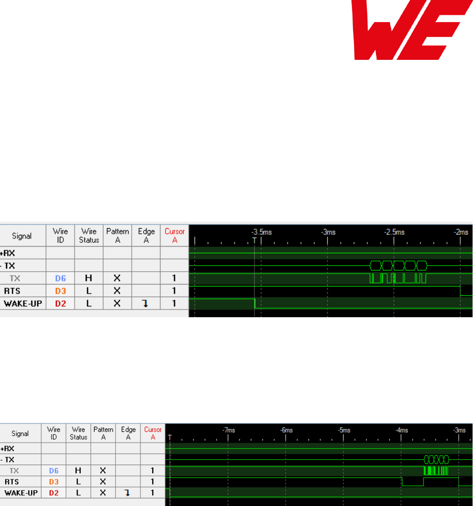
AMB8826_AMB9826_MA_2_0 Page 60 of 84 Date: 03/2018
11.2 Latencies when leaving standby or shutdown
The indication CMD_RESET_IND or CMD_STANDBY_IND (5 bytes in total) are written before the
/RTS pin is pulled back to low level. Therefore, the start-up time is dependent on the UART
baud rate.
The time presented here was measured with the UART default setting of 115200 baud, 8n1.
11.2.1 Wake-up latency from standby
The wake-up time is 1.6 ms.
Figure 4 Wake-up from standby
11.2.2 Wake-up latency from shutdown
The wake-up time is 5ms.
Figure 5 Wake-up from shutdown

AMB8826_AMB9826_MA_2_0 Page 61 of 84 Date: 03/2018
11.3 Latencies during data transfer / packet generation
The data transfer is always buffered, i.e. data received via UART is buffered in the module until
a specific event occurs. Subsequently, the UART reception is interrupted (flow control with /RTS
signal), and the payload data is passed to the internal memory of the wireless transceiver
(FIFO).
By using several UART buffers the time during which the UART is not receiving can be
minimized.
The wireless transmission starts as soon as the first data is available in the transceiver memory.
During the continuous wireless transmission, the remaining payload data is transmitted byte by
byte.
On the receiver side, the FIFO is read as soon as an incoming packet is detected.
If the module detects a packet that requires an ACK, the ACK is sent directly after the packet
reception. The channel access method is always deactivated for ACKs.
In combination with a suitable packet generation method, this procedure enables the
minimisation of the latencies resulting from buffering.
According to ETSI EN 301 391 (access protocol for small data packets on one shared radio
channel) the time for every packet should not exceed 100ms. For slow data rates the packet
size has to be reduced respectively when applying EN 301 391.
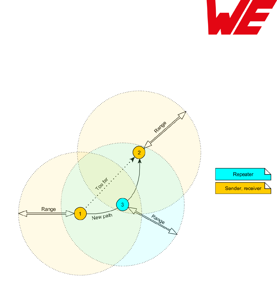
AMB8826_AMB9826_MA_2_0 Page 62 of 84 Date: 03/2018
12 Flooding mesh: Using the repeater functionality
The AMB8826 / AMB9826 module can be run as a repeater to artificially extend the range of
sending devices in an existing network.
Figure 6 Range extension using several repeaters
If the module is configured as repeater, it can be simply added to existing wireless networks
consisting of compatible modules. With this, the newly generated mesh network uses the so-
called “flooding technique” to deliver data packets from their source to their destination device.
The repeater module itself simply listens to the configured channel and forwards all received
packets except the ones addressed to itself. Thereby a random delay is used to avoid RF
packet collision. To reduce traffic on the frequency channel, each repeater device checks before
repetition, if the channel is free and whether it has already sent this packet before or not. Thus,
every repeater sends each packet only once.
In a network with NumRP repeater devices, each data packet is repeated NumRP times.
Therefore each packet that is send from node A to node B forces a traffic of NumRP+1 data
packets in total on the frequency channel.
Besides of this, an AMB8826 / AMB9826 that is configured as repeater supports also the
functions of a standard module. Thus, it can receive data and can initiate the data transmission
to other modules.

AMB8826_AMB9826_MA_2_0 Page 63 of 84 Date: 03/2018
12.1.1 Setup of the network and repeater device
The repeater mode can be enabled with setting bit 0 in the RpFlags.
As ACKs are not supported by the Repeater mode all network members must make
sure that the UserSettings value of MAC_NumRetrys is set to 0.
If the AMB8826 / AMB9826 device is configured as repeater, the following notes have to be
considered:
Requirements on the network:
The repeater devices have to be line-powered (no battery), since due to packet
repetition it demands more energy.
Depending on the data rate, each repeater should repeat a maximum of 2-5 packets per
second to give a good chance that the repeater is not busy with repeating when already
a new packet arrives for repetition. Otherwise, packets can get lost. Please setup your
network such that this requirement is fulfilled. More packets per second will result in
more packet loss as the collision probability is increased.
If the network consists of several layers of repeaters, each layer delays the packet
transmission additionally.
To setup the network all participants have to use the same
RADIO_DefaultRfProfile, RADIO_DefaultRfChannel and
MAC_DefaultAddressMode.
Information for the repeater device:
The repeater module operates in command mode.
Acknowledgements (ACK) of successfully received packets are blocked. If an ACK is
requested by the sending module, the request is ignored. Furthermore, the repeater
does not request any ACK, when repeating a packet.
The “packet sniffer” mode cannot run at the same time as the module is in repeater
mode.
Each time a packet has been repeated a CMD_REPEAT_IND is outputted over UART.
Depending on the address mode, the address of the involved devices is placed in the
CMD_REPEAT_IND telegram. With this the original sender of the RF packet and the
device, that is supposed to receive the packet, can be identified.
Information for the sending and receiving devices:
The senders should send less frequently to avoid packet collision on the frequency
channel and to not exceed the duty cycle.
The repeater devices do not support the feature of ACKs for the successful reception of
the packets. Thus, the sender will never receive ACKs if requested. To ensure that
transmitted packets are successfully received by the destination device, the network
administrator has to integrate his own acknowledging feature in the customer’s
application. To be sure that the sender does not request ACKs the UserSetting
MAC_NumRetrys must be set to 0.
Every repeater sends each packet only once. However, receivers can receive each
packet several times (sent by different repeaters), if there are packets of different
content in the network temporally close to each other. Thus, on the side of the receiving
device, a mechanism can be implemented that filters double packets.
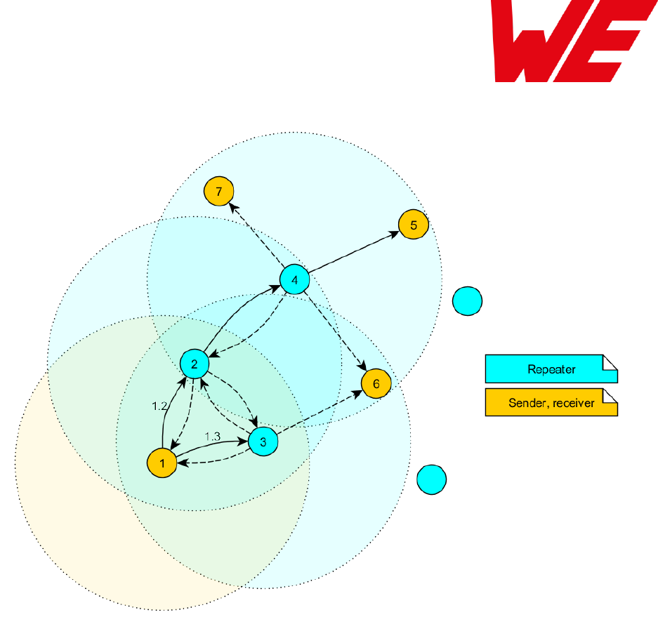
AMB8826_AMB9826_MA_2_0 Page 64 of 84 Date: 03/2018
12.1.2 Example network
Figure 7 Example network
In the example network shown above, the goal is to send a packet from device 1 to 5. Without
the repeater devices, this would be impossible. The steps are as follows:
A. Sender 1 sends a packet.
a. Repeater 2 and 3 receive and accept it at the same time.
B. Device 2 and 3 delay the packet.
a. Repeater 3 sends the packet.
i. Sender 1 and 6 do not accept it, since their addresses are wrong
(unequal 5).
ii. Repeater 2 does not accept it, since it has been already received before
(1.2).
b. Repeater 2 sends the packet.
i. Repeaters 3 does not accept it, since it has been already received before
(1.3).
ii. Sender 1 does not accept it, since its address is wrong (unequal 5).
iii. Repeater 4 receives and accepts the packet.
C. Repeater 4 delays and sends the packet.
a. Sender 6 and 7 do not accept it, since their addresses are wrong (unequal 5).
b. Repeater 2 does not accept it, since it has been already received before (1.2).
c. Receiver 5 accepts it and its successfully delivered (address equals 5)

AMB8826_AMB9826_MA_2_0 Page 65 of 84 Date: 03/2018
Note that the packet forwarded by repeater 2 and 3 would collide in the frequency channel, if
they wouldn’t be randomly delayed (see RP_NumSlots in 8.4.14).
12.1.3 Application in parallel networks
As described above, a repeater device forwards all packets that are received before. If a
network needs to have a bigger throughput of data, a parallel network can be set up, that
relaxes the stress of the primal network. To do so, all sending, receiving and repeater devices of
the parallel network are configured to use a new channel, such that the primal network is not
affected at all by the traffic of the parallel network.

AMB8826_AMB9826_MA_2_0 Page 66 of 84 Date: 03/2018
13 Using the long range mode in AMB8826
The AMB8826 provides several so called “long range modes” that allows to achieve ranges up
to 10km. To enable any long range mode, the parameter RADIO_DefaultRfProfile must be
set to an according value, see chapter 8.4.2 for more information.
To do so the CMD_SET_REQ can be used as it is in case of any other parameter. In this
particular case, it looks as follows:
Format:
Start
signal
Command
Length
SettingsIndex of the
RADIO_DefaultRfProfile
Parameter
value
CS
0x02
0x09
0x02
0x01
0x03
0x0B
Response in case of success:
Start signal
Command | 0x40
Length
Status
CS
0x02
0x49
0x01
0x00
0x4A

AMB8826_AMB9826_MA_2_0 Page 67 of 84 Date: 03/2018
14 Firmware update
We highly recommend having the UART or JTAG accessible in any application to
have the possibility to perform a firmware update.
Firmware updates can only be performed through this interfaces once a module is
implemented into a customer PCB.
14.1 Update using UART0 interface
As long as a firmware is running on the module the module can be updated with the PC utility
"AMBER Config Center” (ACC V3, AMB8826 / AMB9826 HW-V >= 2.2 support is added with
version 3.4.2.5 whereas support for AMB8826 beta HW-V < 2.2 and firmware 1.x.x was
removed) via the serial interface.
Therefore the module must be reset (CMD_RESET_REQ or /RESET pin) while holding the BOOT
pin on a high level until the bootloader is active.
If the module is not directly connected to a PC, at least the UART should be made accessible,
e.g. by means of suitable connectors. Only the UTDX, URXD and GND signals are needed for
this connection. An adapter/converter is required for a PC connection (e.g. the FTDI TTL-323R-
3V3 UART to USB converter).
Neither of the lines of the AMB8826 / AMB9826 is 5V compatible. Applying
overvoltage to any pin may damage the hardware permanently (see chapter 2.2.1).
The pin BOOT must be connected to a high level (while and short after a reset) in order to start
the bootloader. If the BOOT pin is connected to GND the application will start, so for normal
operation the level on the BOOT pin must be pulled to GND (directly or using a pull-down with
e.g. 1kΩ) to make sure the application is started.
The /RESET signal shall be connectable to GND for performing a reset of the module (e.g.
using a push-button which pulls to GND when pressed). The /RESET pin has an internal pull-up
of 100 kΩ.
As an alternative, a host may implement the ARM / TI UART Bootloader according to CC1310
technical reference manual chapter 8. This option also needs the pins BOOT and /RESET to be
switched to the needed levels and the pins UTXD and URXD for communication with the
bootloader.

AMB8826_AMB9826_MA_2_0 Page 68 of 84 Date: 03/2018
Never erase the entire chip. Some memory segments (such as CCFG and
FactorySettings) must be retained if AMBER firmware shall be flashed onto the µC
again.
In the case all flash segments were accidentally erased it is highly recommended to
not flash an AMB8826 / AMB9826 firmware again onto the module. Missing, illegal or
erased parameters/flash segments may lead to module malfunctions.
14.2 Update using JTAG
Using this interface option allows performing a fail-safe firmware update even in case of a
broken firmware or misconfiguration.
The user needs hardware and software tools to be able to perform this procedure. In detail
those are:
Flash adapter for Cortex M µC (supporting TI CC1310)
Caution: not every adapter supports the used connection methods. Recommended
adapters are: “Segger J-Flash” and “TI XDS110v3”
Flasher software according to the used flasher adapter
/RESET, GND and VCC are needed for the JTAG connection
JTAG connection is supported through the module’s Pads i1 to i4
The manual of the EV-Board gives an example of a JTAG connection with a 2*10 pin (2.54mm
pitch) connector for the ARM Cortex M Platforms.
Never erase the entire chip. Some memory segments (such as CCFG and
FactorySettings) must be retained if AMBER firmware shall be flashed onto the µC
again.
Missing, illegal or erased parameters/flash segments may lead to module
malfunctions when AMBER firmware is used.

AMB8826_AMB9826_MA_2_0 Page 69 of 84 Date: 03/2018
15 AMB8826 compatibility to existing proprietary modules
Under certain conditions and settings, the AMB8826 is radio compatible to AMB8626,
AMB8426, AMB8420 and their related USB dongles AMB8665, AMB8465.
To allow interoperability check the following settings:
AMB8626/AMB8665 firmware must be of version 3.4.5 or later, AMB8426/65 firmware
must be 1.2.4 or later
RF profiles / RF settings:
RF-profile 0 (38.4 kBaud) and RF-profile 2 (100 kBaud) are compatible to existing
modules. The remaining profiles are for AMB8826 usage only.
Address mode:
Existing modules only support address mode 0, 1, some may also support address
mode 2.
MAC_DefaultDestAddr and MAC_DefaultNetID are set to the corresponding
Broadcast Addresses (255 and/or 65535), so a CMD_DATA_REQ after a reset in any
MAC_DefaultAddressMode will result in a Broadcast frame. The “old” modules have
selected 0 as default destination Address and NetID
User data size:
Existing modules only support up to 120 bytes user data, some may also support up to
128 bytes payload.
Timings:
Some timings of existing modules (ACK timeouts with retries) may need adjustment, see
chapter 2.1.
Pinout:
The pinout for basic functionality is kept the same as AMB8626 and AMB8426. Thus,
UART_RX, UART_TX and RTS, /RESET, GND, VCC and LED’s remain on the same
pads. Nevertheless, the AMB8826 requires further pins to operate: those pins are
“BOOT” and “WAKE-UP” .
Operation mode:
The AMB8826 only supports Command Mode using the same command structure as
known from previous products but different commands (e.g. CMD_SET_REQ and
CMD_GET_REQ structures were changed for better usability). The transparent mode is
not available on AMB8826.
UART:
The AMB8826 uses 115200 baud 8n1 instead of 9600 baud 8n1 as factory default for
the UART. Users can change this setting to 9600 Baud using the CMD_SET_REQ
command.
Low power mode:
AMB8826 will enable low power modes on UART commands CMD_STANDBY_REQ and
CMD_SHUTDOWN_REQ. In low power mode, the UART is disabled and a wake-up can be
triggered by using the wake-up pin accordingly. The low power modes cannot be
enabled by my means of a pin.

AMB8826_AMB9826_MA_2_0 Page 70 of 84 Date: 03/2018
15.1 Restrictions
AMB8626/AMB8665:
To successfully transmit ACKs from an AMB8826 to an AMB8626/AMB8665 the
parameter MAC_AckTimeout of the AMB8626/AMB8665 must be set to a value of
20ms.
Furthermore, the firmware of the AMB8626/AMB8665 must be of version 3.4.5 or newer.
When using an older firmware version for AMB8626/AMB8665 a network consisting of
AMB8826 and AMB8626/AMB8665 does not support ACKs and
RADIO_DefaultRfProfile 2 may lead to reduced transmission quality.
AMB8426/AMB8465, AMB8420:
To successfully transmit ACKs from an AMB8826 to an AMB8426/AMB8465 the
parameter MAC_AckTimeout of the AMB8426/AMB8465 must be set to a value of
20ms.
Furthermore, the firmware of the AMB8426/AMB8465 must be of version 1.2.4 or newer.

AMB8826_AMB9826_MA_2_0 Page 71 of 84 Date: 03/2018
16 Firmware history
Version 1.x.x
Status “Engineering” of firmware
For AMB8826 HW-V <= 2.1 “Engineering” only
Version 2.0.0 Beta
Status “Engineering” of firmware
For AMB8826 HW-V = 2.2 “Engineering” only
Known issues:
o This is not the final release! Major changes will occur until release.
o FactorySettings and UserSettings location is not on the final Address, yet
o An update from firmware version 1.0.0 to version 2.0.0 Beta is not possible due to
the HW differences
Version 2.0.0
For CC1310 Revision B only
For AMB8826 HW-Version = 2.2 “Engineering” and 2.3 “Release”
Status “Release” firmware
New additional radio profiles for AMB8826/65 (4, 5)
Added temperature dependant frequency compensation for radio profile 3
Sniffer mode can be enabled using the CfgFlags
o Removed UserSetting RADIO_SnifferModeEnabled
Known issues:
o TI-RTOS: Additional latencies up to 5ms due to task priorities may occur
o An update from firmware version 1.0.0 to version 2.0.0 is not possible due to the HW
differences
o Works with reservations on AMB8826 HW-V 2.2. You are advised to not use Profile
3 with AMB8826 HW-V 2.2 and firmware 2.0.0 as the temperature compensation is
selected for HW-V 2.3
Version 2.x.x
Not used pins are pulled to low level.
Known issues:
o TI-RTOS: Additional latencies up to 5ms due to task priorities may occur
o An update from firmware version 1.0.0 to version 2.x.x is not possible due to the HW
differences
o Works with reservations on AMB8826 HW-V 2.2. You are advised to not use radio
profile 3 with AMB8826 HW-V 2.2 and firmware 2.0.0 as the temperature
compensation is selected for HW-V 2.3
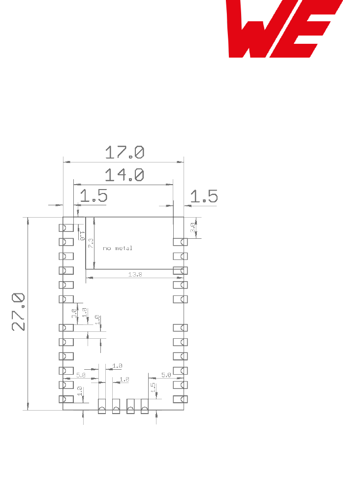
AMB8826_AMB9826_MA_2_0 Page 72 of 84 Date: 03/2018
17 Hardware integration
17.1 Footprint and dimensions
Figure 8: Footprint and dimensions for the AMB8826 / AMB9826, [mm]
The following points have to be considered:
To avoid the risk of short circuits, a minimum clearance of at least 14 mm between the
opposing pad rows has to be maintained! No Routing on the top layer of a carrier PCB
(i.e. “under” the module) shall be performed.
For the AMB8826 / AMB9826 variant with integrated antenna the marked corner area
of 7.3 x 13.8 mm has to be kept free from metal, on any layer.
The four bottom side pads are optionally for the firmware update using JTAG can be
left open when JTAG update is not needed in the customer’s application.
This footprint is also compatible to AMB8626, AMB8426, AMB4426 and AMB3626.

AMB8826_AMB9826_MA_2_0 Page 73 of 84 Date: 03/2018
18 Design in guide
18.1 Advice for schematic and layout
For users with less RF experience it is advisable to closely copy the relating evaluation board
with respect to schematic and layout, as it is a proven design. The layout should be conducted
with particular care, because even small deficiencies could affect the radio performance and its
range or even the conformity.
The following general advice should be taken into consideration:
A clean power supply is strongly recommended. Interference, especially oscillation can
severely restrain range and conformity.
Variations in voltage level should be avoided.
LDOs, properly designed in, usually deliver a proper regulated voltage.
Blocking capacitors and a ferrite bead in the power supply line can be included to filter
and smoothen the supply voltage when necessary.
No fixed values can be recommended, as these depend on the circumstances of the
application (main power source, interferences etc.).
Frequently switching the module on and off, especially with a slowly changing voltage
level of the power supply, can lead to erratic behavior, in rare cases even as far as
damaging the module or the firmware. The use of an external reset IC can solve this
matter.
Elements for ESD protection should be placed on all pins that are accessible from the
outside and should be placed close to the accessible area. For example, the RF-pin is
accessible when using an external antenna and should be protected.
ESD protection for the antenna connection must be chosen such as to have a minimum
effect on the RF signal. For example, a protection diode with low capacitance such as
the LXES15AAA1-100 or a 68 nH air-core coil connecting the RF-line to ground give
good results.
Placeholders for optional antenna matching or additional filtering are recommended.
The antenna path should be kept as short as possible.
Again, no fixed values can be recommended, as they depend on the influencing
circumstances of the application (antenna, interferences etc.).
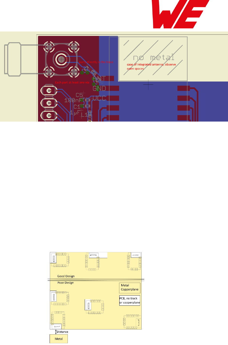
AMB8826_AMB9826_MA_2_0 Page 74 of 84 Date: 03/2018
Figure 9: Layout
To avoid the risk of short circuits and interference there should be no routing underneath
the module on the top layer of the baseboard.
On the second layer, a ground plane is recommended, to provide good grounding and
shielding to any following layers and application environment.
In case of integrated antennas it is required to have areas free from ground. This area
should be copied from the evaluation board.
The area with the integrated antenna must overlap with the carrier board and should not
protrude, as it is matched to sitting directly on top of a PCB.
Modules with integrated antennas should be placed with the antenna at the edge of the
main board. It should not be placed in the middle of the main board or far away from the
edge. This is to avoid tracks beside the antenna.
Filter and blocking capacitors should be placed directly in the tracks without stubs, to
achieve the best effect.
Antenna matching elements should be placed close to the antenna / connector, blocking
capacitors close to the module.
Ground connections for the module and the capacitors should be kept as short as
possible and with at least one separate through hole connection to the ground layer.
ESD protection elements should be placed as close as possible to the exposed areas.
Figure 10 Placement of the module with integrated antenna
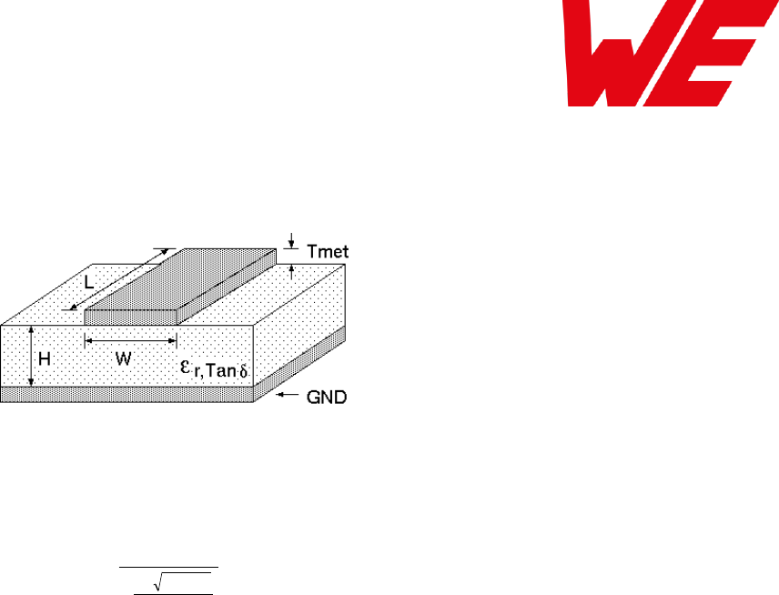
AMB8826_AMB9826_MA_2_0 Page 75 of 84 Date: 03/2018
18.2 Dimensioning of the 50 Ohm micro strip
The antenna track has to be designed as a 50 Ohm feed line.
Figure 11 Dimensioning the antenna feed line as micro strip
The width W for a micro strip can be calculated using the following equation:
met
T
e
H
Wr
87
41.150
98.5
25.1
Equation 1 Parameters of the antenna feeding line
Example: a FR4 material with r = 4.3, a height H = 1000 µm and a copper thickness of Tmet= 18
µm will lead to a trace width of W ~ 1.9 mm. To ease the calculation of the micro strip line (or
e.g. a coplanar) many calculators can be found in the internet.
As rule of thumb a distance of about 3 x W should be observed between the micro strip
and other traces / ground.
The micro strip refers to ground, therefore there has to be the ground plane underneath
the trace.
Keep the feeding line as short as possible.

AMB8826_AMB9826_MA_2_0 Page 76 of 84 Date: 03/2018
18.3 Antenna solutions
There exist several kinds of antennas, which are optimized for different needs. Chip antennas
are optimized for minimal size requirements but at the expense of range, PCB antennas are
optimized for minimal costs, and are generally a compromise between size and range. Both
usually fit inside a housing. Range optimization in general is at the expense of space. Antennas
that are bigger in size, so that they would probably not fit in a small housing, are usually
equipped with a RF connector. A benefit of this connector may be to use it to lead the RF signal
through a metal plate (e.g. metal housing, cabinet).
As a rule of thumb a minimum distance of Lambda/10 (3.5 cm @ 868 MHz, 1.2 cm @ 2.44
GHz) from the antenna to any other metal should be kept. Metal placed further away will not
directly influence the behavior of the antenna, but will anyway produce shadowing.
Keep the antenna away from large metal objects as far as possible to avoid
electromagnetic field blocking.
In the following chapters, some special types of antenna are described.
18.3.1 Lambda/4 radiator
An effective antenna is a Lambda/4 radiator. The simplest realization is an 8.6 cm long piece of
wire for 868 MHz, respectively a 3.1 cm long piece of wire for 2.44 GHz. This radiator needs a
ground plane at its feeding point. Ideally, it is placed vertically in the middle of the ground plane.
As this is often not possible because of space requirements, a suitable compromise is to bend
the wire away from the PCB respective to the ground plane. The Lambda/4 radiator has
approximately 40 Ohm input impedance, therefore matching is not required.
18.3.2 Chip antenna
There are many chip antennas from various manufacturers. The benefit of a chip antenna is
obviously the minimal space required and reasonable costs. However, this is often at the
expense of range. For the chip antennas, reference designs should be followed as closely as
possible, because only in this constellation can the stated performance be achieved.
18.3.3 PCB antenna
PCB antenna designs can be very different. The special attention can be on the miniaturization
or on the performance. The benefits of the PCB antenna are their small / not existing (if PCB
space is available) costs, however the evaluation of a PCB antenna holds more risk of failure
than the use of a finished antenna. Most PCB antenna designs are a compromise of range and
space between chip antennas and connector antennas.
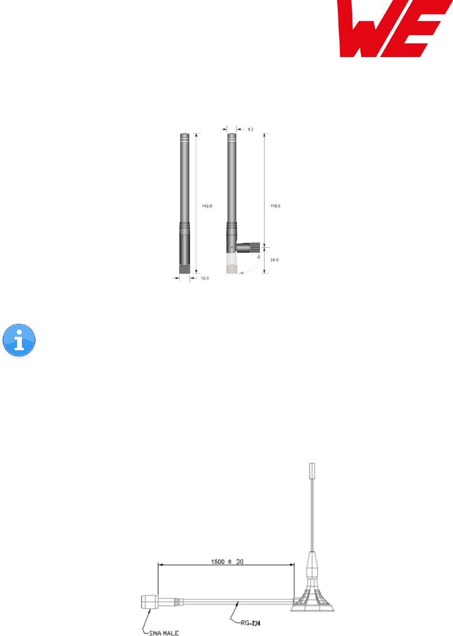
AMB8826_AMB9826_MA_2_0 Page 77 of 84 Date: 03/2018
18.3.4 Antennas provided by AMBER
18.3.4.1 AMB1981 – 868 MHz dipole antenna
Ideally suited for applications where no ground plane is available.
Figure 12 AMB1981:
868 MHz dipole-antenna
The AMB1981 antenna can be also used for 902MHz – 928MHz range.
18.3.4.2 AMB1982 – 868 MHz magnetic base antenna
Well suited for applications where the RF is lead through a metal wall that could serve as
ground plane to the antenna.
Figure 13 AMB1982: 868 MHz magnet foot
antenna with 1.5 m antenna cable

AMB8826_AMB9826_MA_2_0 Page 78 of 84 Date: 03/2018
The AMB1982 is a kind of Lambda/4 radiator and therefore needs a ground plane at
the feeding point.
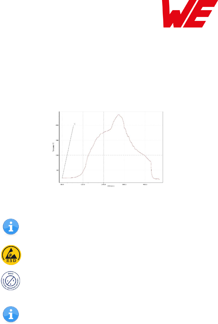
AMB8826_AMB9826_MA_2_0 Page 79 of 84 Date: 03/2018
19 Manufacturing information
The assembly contains moisture sensitive devices of the MSL classification 3. Only the
dry packed Tape & Reel devices are suitable for the immediate processing in a reflow
process.
Further information concerning the handling of moisture sensitive devices, (e.g. drying)
can be obtained from the IPC/ JEDEC J-STD-033.
Recommendations for the temperature profile for the soldering furnace cannot be made,
as it depends on the substrate board, the number and characteristics of the
components, and the soldering paste used (consult your EMS).
Figure 14 shows a soldering curve that had been used for a 31 cm2 carrier board for single-side
assembly.
Figure 14 Example of a temperature profile
Caution: Must be adjusted to the characteristics of the carrier board!
To ensure the mechanical stability of the modules it is recommended to solder all
pads of the module to the base board, even if they are not used for the application.
Caution! ESD sensitive device.
Care should be taken when handling the device in order to prevent permanent
damage.
MSL 3
Caution! This assembly contains moisture sensitive components.
Care should be taken when processing the device according to IPC/JEDEC J-STD-
033.
Since the module itself is not fused the voltage supply shall be fed from a limited
power source according to clause 2.5 of EN 60950-1.

AMB8826_AMB9826_MA_2_0 Page 80 of 84 Date: 03/2018
20 References
[1] „CC1310 SimpleLink™ Ultralow Power Sub-1-GHz Wireless MCU”, Texas Instruments
[2] “CC13xx, CC26xx SimpleLink Wireless MCU Technical Reference Manual”, Texas
Instruments
[3] „CC1310 SimpleLink Wireless MCU Silicon Errata“, Texas Instruments
[4] „AMB8826 Datasheet”, AMBER wireless GmbH
[5] “AMB8926 Datasheet”, AMBER wireless GmbH

AMB8826_AMB9826_MA_2_0 Page 81 of 84 Date: 03/2018
21 Regulatory compliance information
21.1 Important notice
The use of RF frequencies is limited by national regulations. The AMB8826 has been designed
to comply with the R&TTE directive 1999/5/EC of the European Union (EU).
The AMB8826 can be operated without notification and free of charge in the area of the
European Union. However, according to the R&TTE directive, restrictions (e.g. in terms of duty
cycle, frequency or maximum allowed RF power) may apply.
Conformity assessment of the final product
The AMB8826 is a subassembly. It is designed to be embedded into other products (products
incorporating the AMB8826 are henceforward referred to as "final products").
It is the responsibility of the manufacturer of the final product to ensure that the final product is
in compliance with the essential requirements of the European Union's Radio &
Telecommunications Terminal Equipment (R&TTE) directive.
The conformity assessment of the subassembly AMB8826 carried out by AMBER wireless
GmbH does not replace the required conformity assessment of the final product in accordance
to the R&TTE directive!
Exemption clause
Relevant regulation requirements are subject to change. AMBER wireless GmbH does not
guarantee the accuracy of the before mentioned information. Directives, technical standards,
procedural descriptions and the like may be interpreted differently by the national authorities.
Equally, the national laws and restrictions may vary with the country. In case of doubt or
uncertainty, we recommend that you consult with the authorities or official certification
organizations of the relevant countries. AMBER wireless GmbH is exempt from any
responsibilities or liabilities related to regulatory compliance.

AMB8826_AMB9826_MA_2_0 Page 82 of 84 Date: 03/2018
21.1.1 FCC Compliance statement AMB9826 & AMB9826-1
FCC ID: R7TAMB9826
This device complies with Part 15 of the FCC Rules.
Operation is subject to the following two conditions:
(1) this device may not cause harmful interference, and
(2) this device must accept any interference received, including interference that may cause
undesired operation.
(FCC 15.19)
Modifications (FCC 15.21)
Caution: Changes or modifications for this equipment not expressly approved by AMBER
wireless may void the FCC authorization to operate this equipment.
21.1.2 IC Compliance statement AMB9826 & AMB9826-1
Certification Number: 5136A- AMB9826
This device complies with Industry Canada licence-exempt RSS standard(s). Operation is
subject to the following two conditions: (1) this device may not cause harmful interference, and
(2) this device must accept any interference received, including interference that may cause
undesired operation.
Le présent appareil est conforme aux CNR d'Industrie Canada applicables aux appareils radio
exempts de licence. L'exploitation est autorisée aux deux conditions suivantes : (1) l'appareil ne
doit pas produire de brouillage, et (2) l'utilisateur de l'appareil doit accepter tout brouillage
radioélectrique subi, même si le brouillage est susceptible d'en compromettre le
fonctionnement.
21.1.3 FCC and IC Requirements to OEM integrators
This module has been granted modular approval. OEM integrators for host products may use
the module in their final products without additional FCC / IC (Industry Canada) certification if
they meet the following conditions. Otherwise, additional FCC / IC approvals must be obtained.
The host product with the module installed must be evaluated for simultaneous transmission
requirements.
The users manual for the host product must clearly indicate the operating requirements and
conditions that must be observed to ensure compliance with current FCC / IC RF exposure
guidelines.
To comply with FCC / IC regulations limiting both maximum RF output power and human
exposure to RF radiation, the maximum antenna gain including cable loss in a mobile-only
exposure condition must not exceed 2dBi.
A label must be affixed to the outside of the host product with the following statements:
This device contains FCCID: R7TAMB9826
This equipment contains equipment certified under ICID: 5136A-AMB9826

AMB8826_AMB9826_MA_2_0 Page 83 of 84 Date: 03/2018
The final host / module combination may also need to be evaluated against the FCC Part 15B
criteria for unintentional radiators in order to be properly authorized for operation as a Part 15
digital device.
If the final host / module combination is intended for use as a portable device (see
classifications below) the host manufacturer is responsible for separate approvals for the SAR
requirements from FCC Part 2.1093 and RSS-102.
OEM Requirements:
The OEM must ensure that the following conditions are met.
End users of products, which contain the module, must not have the ability to alter the
firmware that governs the operation of the module. The agency grant is valid only when the
module is incorporated into a final product by OEM integrators.
The end-user must not be provided with instructions to remove, adjust or install the module.
The Original Equipment Manufacturer (OEM) must ensure that FCC labeling requirements
are met. This includes a clearly visible label on the outside of the final product. Attaching a
label to a removable portion of the final product, such as a battery cover, is not permitted.
The label must include the following text:
Contains FCC ID: R7TAMB9826
The enclosed device complies with Part 15 of the FCC Rules. Operation is subject to
the following two conditions: (i.) this device may not cause harmful interference and
(ii.) this device must accept any interference received, including interference that may cause
undesired operation.
When the device is so small or for such use that it is not practicable to place the statement
above on it, the information required by this paragraph shall be placed in a prominent location in
the instruction manual or pamphlet supplied to the user or, alternatively, shall be placed on the
container in which the device is marketed. However, the FCC identifier or the unique identifier,
as appropriate, must be displayed on the device.
The user manual for the end product must also contain the text given above.
Changes or modifications not expressly approved could void the user's authority to operate
the equipment.
The OEM must ensure that timing requirements according to 47 CFR 15.231(a-c) are met.
The OEM must sign the OEM Modular Approval Agreement with xxxxx
The module must be used with only the following approved antenna(s).
21.1.4 AMB9826 & AMB9826-1
The module variants HVIN AMB9826 and AMB9826-1 collected in the PMN AMB9826 are
identicall in enclosure, appearance, PCB design and bands/technologies.
The only difference is, that in AMB9826 an integrated Chip Antenna is used and for the
AMB9826-1 an external λ/4 Antenna is used.

AMB8826_AMB9826_MA_2_0 Page 84 of 84 Date: 03/2018
22 Important information
22.1 Exclusion of liability
AMBER wireless GmbH \subsection{presumes that the information in this document is correct at
the time of publication. However, AMBER wireless GmbH reserves the right to modify technical
specifications or functions of its products or discontinue the production of these products or the
support of one of these products without any written announcement or notification to customers.
The customer must make sure that the information used is valid. AMBER wireless GmbH does
not assume any liability for the use of its products. Amber wireless GmbH does not grant
licenses for its patent rights or for any other of its intellectual property rights or third-party rights.
Customers bear responsibility for compliance of systems or units in which AMBER wireless
products are integrated with applicable legal regulations.
22.2 Trademarks
AMBER wireless® is a registered trademark of AMBER wireless GmbH
All other trademarks, registered trademarks, and product names are the exclusive property of
the respective owners.
22.3 Usage restriction
AMBER wireless products are not approved for use in life-supporting or life-sustaining systems
or units or other systems whose malfunction could result in serious bodily injury to the user.
Moreover, AMBER wireless products are not approved for use as key components of any life-
supporting or life-sustaining system or unit whose malfunction could result in the failure of the
life-supporting system or unit or could affect its safety or effectiveness. AMBER wireless
customers who use these products in such applications or sell them for such usage act at their
own risk and must relieve AMBER wireless GmbH from all damages that may result from the
sale for unsuitable purposes or unsuitable usage.
By using AMBER wireless products, the user agrees to these terms and conditions.
Copyright © 2018, AMBER wireless GmbH. All rights reserved.
Würth Elektronik eiSos GmbH & Co KG
Phone +49.651.993.550
Email info@amber-wireless.de
Internet www.we-online.com
www.amber-wireless.de