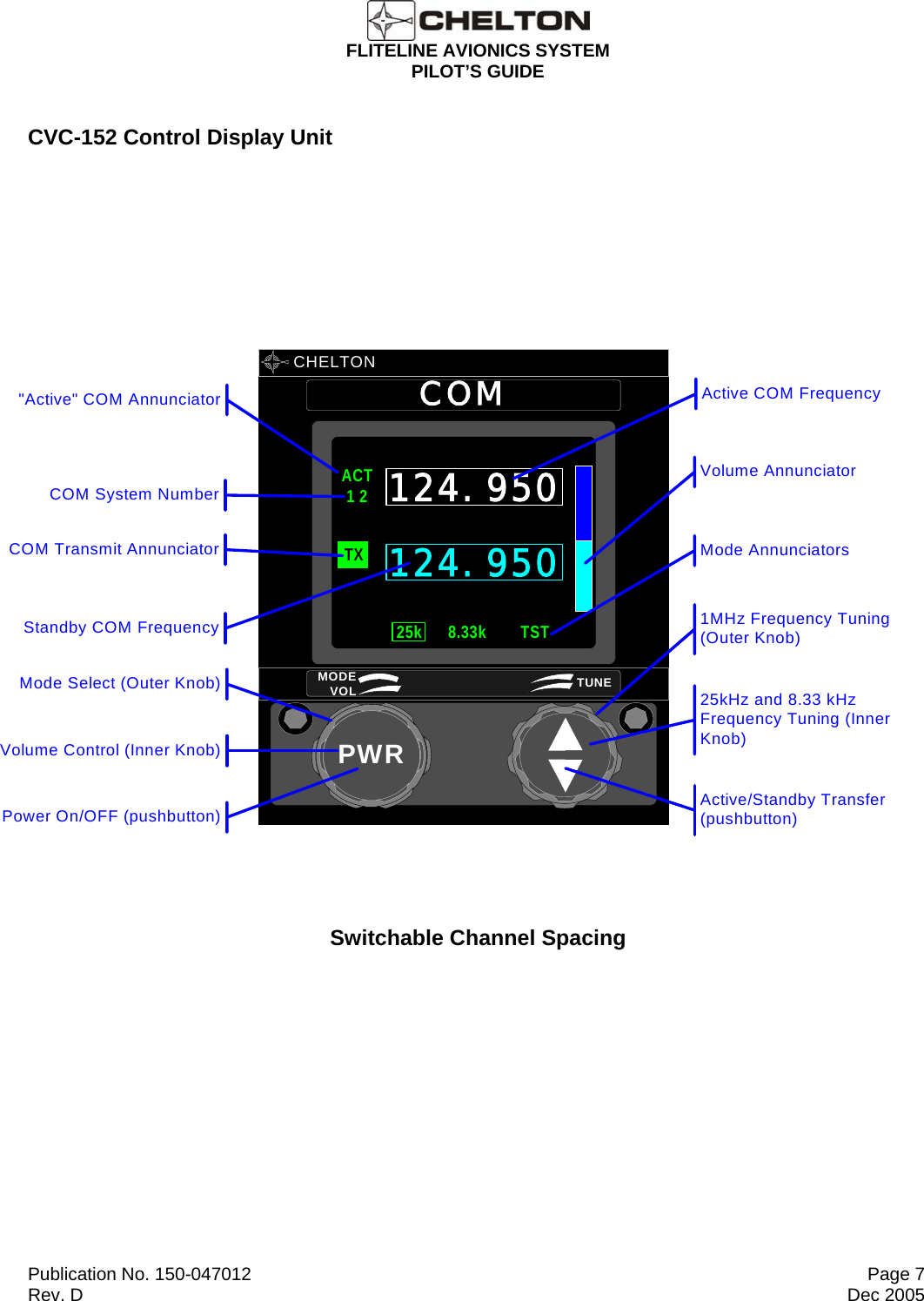
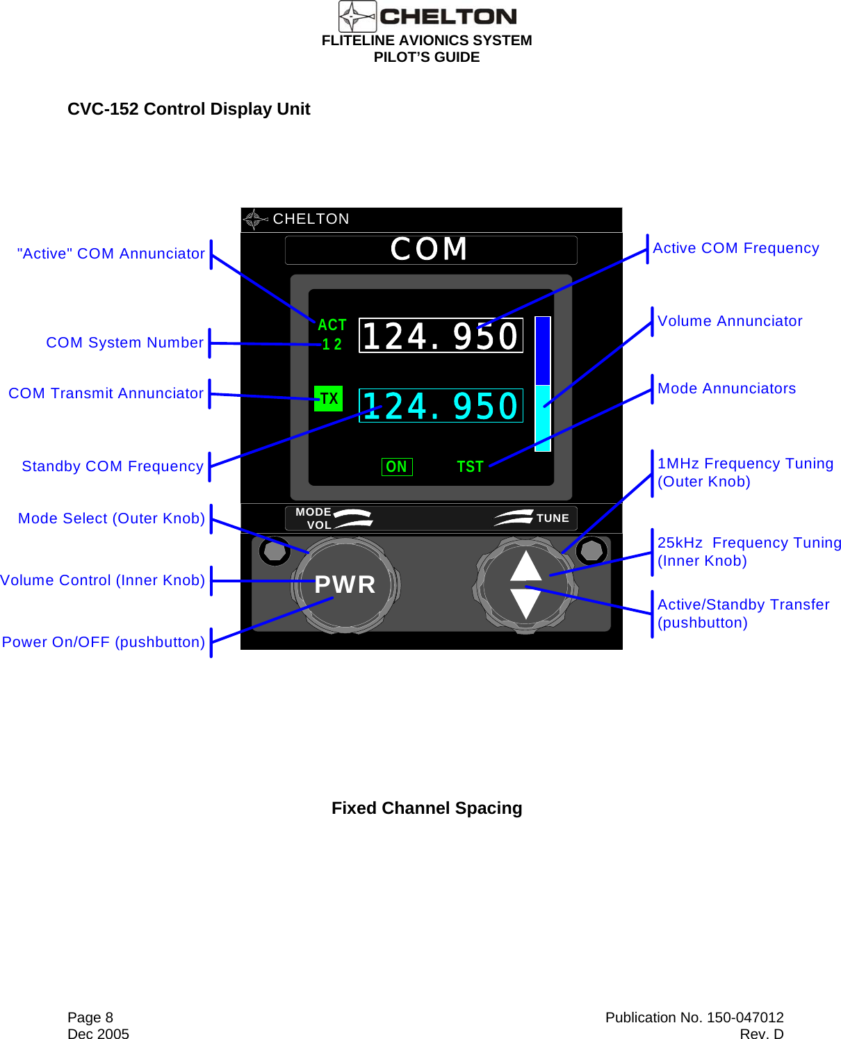
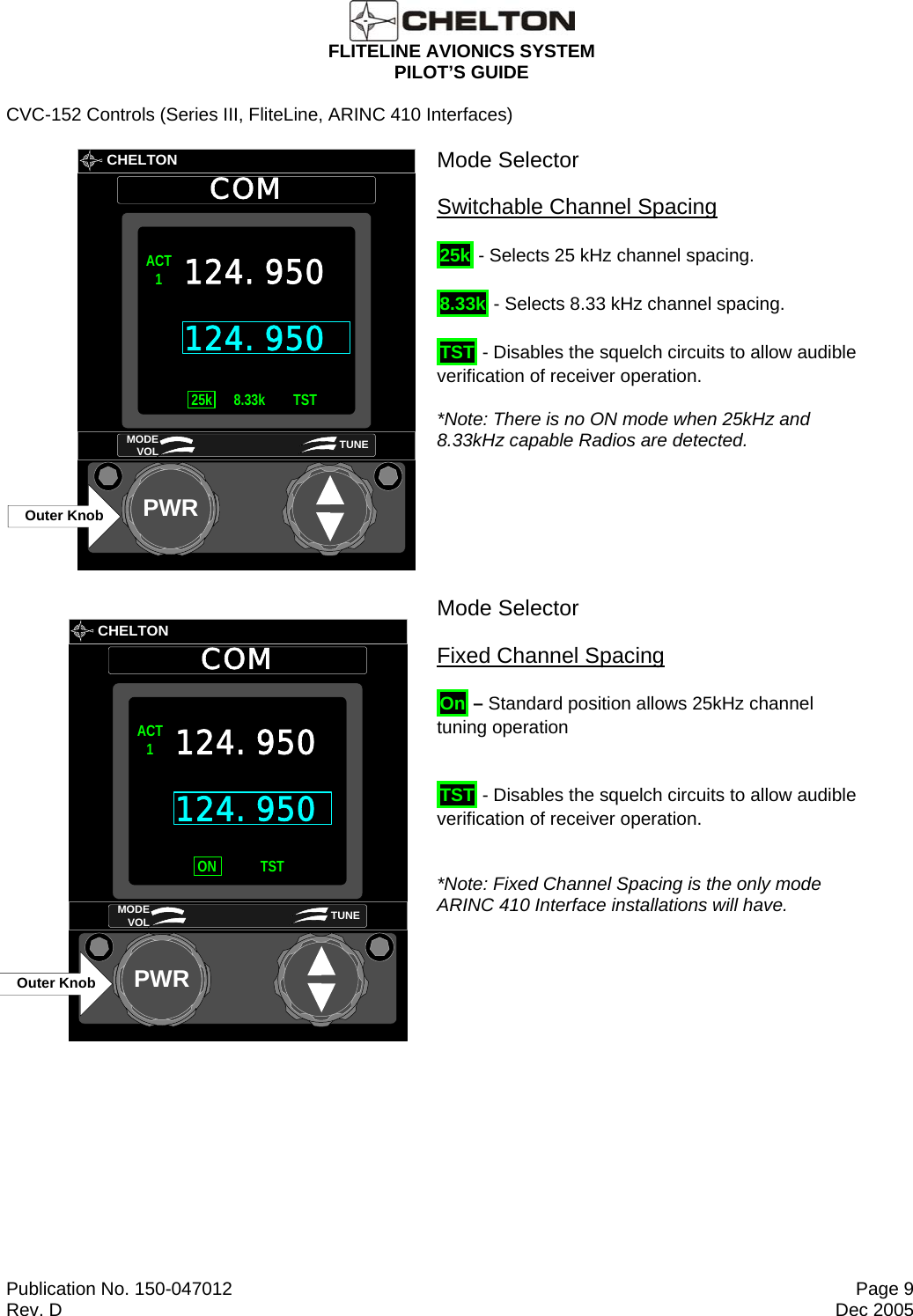
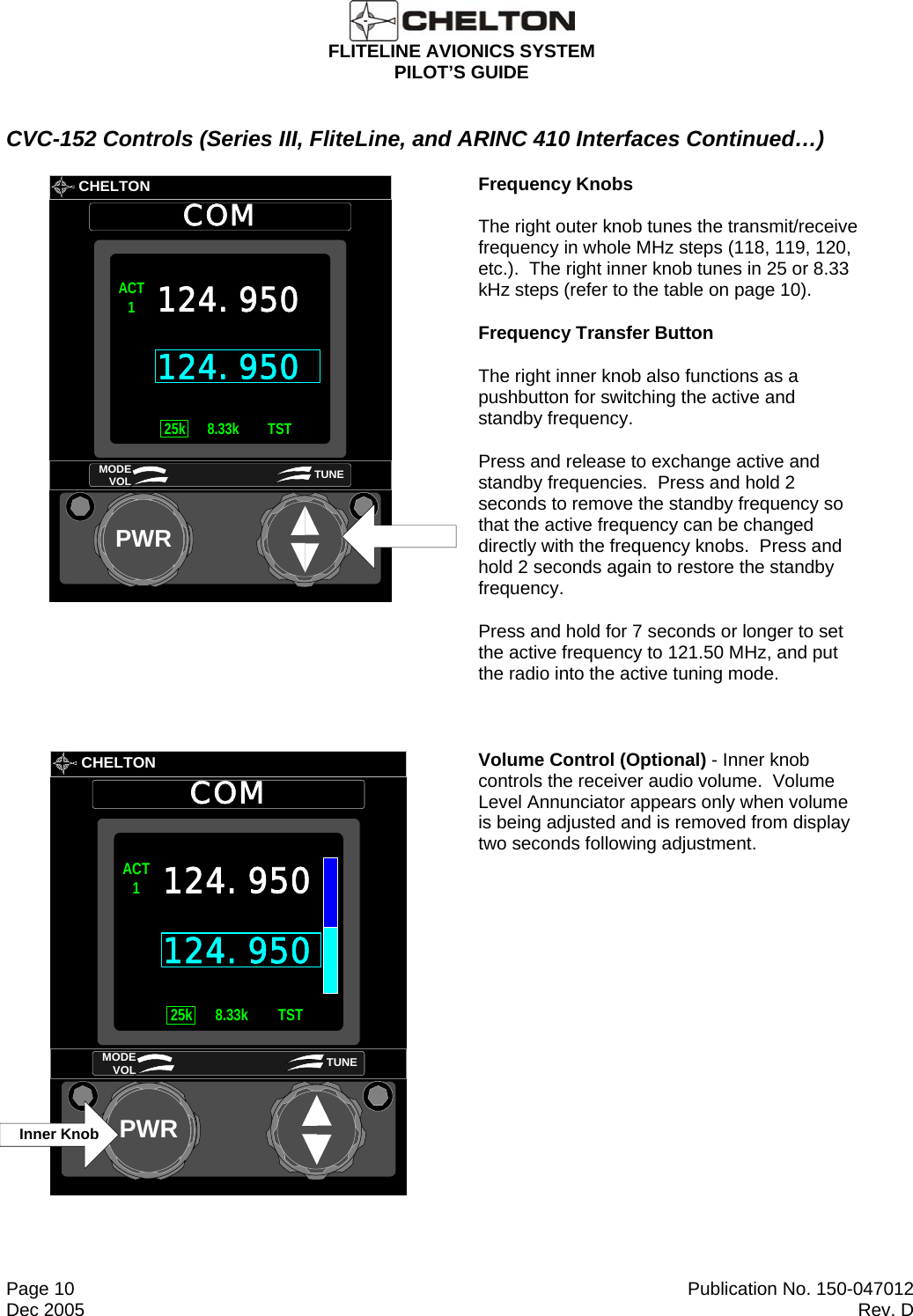
Wulfsberg Electronics Division CVC-151 VHF ATC Communication Transceiver User Manual 150 047012 D

Wulfsberg Electronics Division VHF ATC Communication Transceiver 150 047012 D

User manual

 APPLICATION   REVISIONS REV  D NEXT ASSEMBLY  FINAL ASSEMBLY  REV  DESCRIPTION DATE APPROVED APPROVED    A  Initial Release per DCN W3749 6-18-04 V Wallace J Markham SH 1 B  Revised per DCN W3905  12-23-04 V Wallace J Markham C  Revised per DCN W4435  4-30-04 V Wallace J Markham D  Revised per DCN W4917  12-21-05  V Wallace  Bob Evans                          DWG. NO.           150-047012    THIS DOCUMENT CONTAINS PROPRIETARY INFORMATION OF WULFSBERG ELECTRONICS, A CHELTON GROUP COMPANY, NEITHER RECEIPT NOR POSSESSION THEREOF CONFERS ANY RIGHT TO REPRODUCE OR USE, OR DISCLOSE, IN WHOLE OR IN PART, ANY SUCH INFORMATION WITHOUT WRITTEN AUTHORIZATION FROM WULFSBERG ELECTRONICS   APPROVALS DATE   DRAWN   C Gregory   6-18-04 CHECKED   H Schnieder   6-18-04 PILOT'S GUIDE,  AVIONICS SYSTEMS, FLITELINE ™  ENGINEER   J Markham   6-18-04 ISSUED   V Wallace   6-18-04 SIZE ACAGE CODE 1B7G3 DWG NO. 150-047012  REV D  Typed signatures indicate approval.  Handwritten signature approval of this document is on file at Wulfsberg Electronics, Prescott, Arizona. SCALE:   NONE  DO NOT SCALE DRAWING
            This page intentionally left blank.
 FLITELINE AVIONICS SYSTEM PILOT’S GUIDE  Page 2  Publication No. 150-047012 Dec 2005  Rev. D Table of Contents INTRODUCTION....................................................................................................................................................4 FLITELINE VHF COMMUNICATION SYSTEM (FLITECOMM)............................................................................5 GENERAL DESCRIPTION CVC-151.......................................................................................................................... 5 GENERAL DESCRIPTION CVC-152.......................................................................................................................... 5 CVC-152 DISPLAY (SERIES III AND FLITELINE INTERFACE – FAILURE INDICATION).................................................. 12 OPERATING THE CVC-152................................................................................................................................... 13 VHF COM SYSTEM BLOCK DIAGRAM (TYPICAL).................................................................................................... 16 FLITELINE VHF NAVIGATION SYSTEM (FLITENAV AND FLITEDME) ..........................................................17 GENERAL DESCRIPTION CVN-251........................................................................................................................ 17 GENERAL DESCRIPTION CDM-451 ....................................................................................................................... 17 GENERAL DESCRIPTION CVN-252........................................................................................................................ 18 LIMITATIONS ........................................................................................................................................................ 18 CVN-252 CONTROLS (SERIES III AND FLITELINE INTERFACE) ................................................................................ 20 CVN-252 CONTROLS (SERIES III AND FLITELINE INTERFACE - FAILURE INDICATION)............................................... 24 CVN-252 CONTROLS (SERIES III AND FLITELINE INTERFACE - DME HOLD OPERATION) ......................................... 25 CVN-252 CONTROLS (ARINC 410 INTERFACE).................................................................................................... 26 CVN-252 CONTROLS (ARINC 410 INTERFACE - DME HOLD OPERATION) ............................................................. 27 OPERATING THE CVN-252................................................................................................................................... 28 GENERAL DESCRIPTION SD-442 ..........................................................................................................................30 VHF NAV SYSTEM BLOCK DIAGRAM (TYPICAL)..................................................................................................... 33 FLITELINE AUTOMATIC DIRECTION FINDER (ADF) ......................................................................................34 GENERAL DESCRIPTION ....................................................................................................................................... 34 CDF-552 CONTROLS (SERIES III AND FLITELINE INTERFACE) ................................................................................ 36 CDF-552 CONTROLS (SERIES III AND FLITELINE INTERFACE – FAILURE INDICATION) .............................................. 42 CDF-552 CONTROLS (BCD INTERFACE)............................................................................................................... 43 OPERATING THE CDF-552 ................................................................................................................................... 45 ADF SYSTEM BLOCK DIAGRAM (TYPICAL)............................................................................................................. 47 FLITELINE DUAL VHF COM AND VHF NAV CONTROL DISPLAY SYSTEM .................................................48 GENERAL DESCRIPTION ....................................................................................................................................... 48 LIMITATIONS ........................................................................................................................................................ 48 CCN-955 CONTROLS .......................................................................................................................................... 49 CCN-955 CONTROLS .......................................................................................................................................... 50 OPERATING THE CCN-955................................................................................................................................... 51
 FLITELINE AVIONICS SYSTEM PILOT’S GUIDE  Publication No. 150-047012  Page 3 Rev. D  Dec 2005 FLITELINE ATC TRANSPONDER SYSTEM (FLITEXPDR) ..............................................................................53 GENERAL DESCRIPTION CTR-352........................................................................................................................ 53 CTR-352 CONTROLS (ARINC-410 OCTAL INTERFACE)......................................................................................... 55 OPERATING THE CTR-352 ................................................................................................................................... 60 ATC SYSTEM BLOCK DIAGRAM (TYPICAL)............................................................................................................. 62 FLITELOGIC EFIS TUNING FEATURES............................................................................................................63 GENERAL DESCRIPTION ....................................................................................................................................... 63 OPERATING THE CONTROL DISPLAYS WITH EFIS................................................................................................... 63 CONFIGURATION STATUS PAGE (ALL UNITS)..............................................................................................64 LIMITATIONS.......................................................................................................................................................66
 FLITELINE AVIONICS SYSTEM PILOT’S GUIDE  Page 4  Publication No. 150-047012 Dec 2005  Rev. D  Introduction The FliteLine™ Avionics Systems represent the next generation of Chelton avionics.  The FliteLine Control Display units are subsystems of the Chelton Avionics FliteLine Systems.  The FliteLine NAV/COM/ADF/ATC Control Displays are one of several methods of controlling the Chelton Avionics FliteLine remote-mounted avionics systems. The FliteLine name builds from the reputation and heritage that Wulfsberg™ has enjoyed with the Flitecomm™ and Flitefone® products.  The new FliteLine products are the latest line of Chelton's remote-mounted avionics.  In addition to the Control Display units, the individual systems within the FliteLine product line include: FliteCOMM™, FliteNAV™, FliteXPDR™, and FliteDME™
 FLITELINE AVIONICS SYSTEM PILOT’S GUIDE  Publication No. 150-047012  Page 5 Rev. D  Dec 2005 FliteLine VHF Communication System (FliteCOMM) General Description CVC-151 The FliteLine CVC-151 is an all digital DSP VHF Comm Transceiver, built and designed to ARINC Air Transport specifications. The Transceiver is designed to meet the latest ATC environment, all future CNS ATN requirements, and has provisions for VDL Mode 2 and VDL Mode 3. The CVC-151 features a 20 watt solid-state transmitter, is compliant with 25 kHz or 8.33 kHz spacing and the architecture is standard ARINC 429 which supports interface to FMS systems and the Chelton RMS 555 Radio Management System. The CVC-151 Transceiver is interchangeable with current Series III VHF Comm Transceivers using a special mounting tray adapter. Features   8.33 kHz and/or 25 kHz Channel Spacing  FM Immunity  Continuous Transmit Capability (at reduced power)   Built-in SELCAL and ACARS Capability   New Color LCD Controller: CVC-152 single Com Control Display or Multi-function color Nav/Com CCN-955 CD   Increased System Self-Test and BIT   ARINC 429 Digital Data Bus   118.000-136.975 MHz Standard Frequency Range   118.000 -151.975 MHz Extended Frequency Range Option   Weight and Volume Savings Compared to Series III VC-401B   Provisions for VDL Mode 2 and VDL Mode 3  General Description CVC-152 The Chelton CVC-152 Control Display Unit is available in versions for use with transceivers with fixed channel spacing (25 kHz or 8.33 kHz), and for units with switchable (25 kHz and 8.33 kHz) channel spacing. The CVC-152 is a direct replacement for the Chelton CD-402B and CD-402C Control Display Units. The CVC-152 Control Display Unit provides a simultaneous readout of two frequencies:  The active frequency in the upper display and, immediately below it, the standby frequency.  Frequency switching is accomplished by simply pressing a frequency transfer button.  The Transmit Annunciator (Tx) appears in the display when RF is present at the output of the transceiver, providing positive proof-of-operation.  When the CVC-152 Control Display Unit is turned on, a diagnosis of all critical circuits begins, and continues until the System is turned off.  If a fault is detected at any time, a FAIL annunciation appears in the display. The CVC-152 Control Display Unit has a nonvolatile memory which allows it to remember the last frequencies displayed, indefinitely, even when power is removed.  This feature prevents momentary power interrupts from affecting the system, and allows the last frequencies used to appear immediately when the System is turned on.
 FLITELINE AVIONICS SYSTEM PILOT’S GUIDE  Page 6  Publication No. 150-047012 Dec 2005  Rev. D The CVC-152 Communication Control Display Unit is designed to interface with Chelton FliteLine Communications Radios (CVC-151), Chelton Series III Communications Radios (VC-401B and VC-401C in the VCS 40 Systems), and Collins Communication Radios with the ARINC 410 (2x5) Interfaces.
 FLITELINE AVIONICS SYSTEM PILOT’S GUIDE  Publication No. 150-047012  Page 7 Rev. D  Dec 2005 CVC-152 Control Display Unit                                      Switchable Channel Spacing       CHELTON COMPWR124.950ACT1 225k TST8.33k124.950MODE VOL TUNE 25kHz and 8.33 kHz Frequency Tuning (Inner Knob)1MHz Frequency Tuning (Outer Knob)Active/Standby Transfer (pushbutton)Power On/OFF (pushbutton)Volume Control (Inner Knob)Mode Select (Outer Knob)Volume AnnunciatorMode AnnunciatorsCOM System Number"Active" COM AnnunciatorStandby COM FrequencyActive COM FrequencyTXCOM Transmit Annunciator
 FLITELINE AVIONICS SYSTEM PILOT’S GUIDE  Page 8  Publication No. 150-047012 Dec 2005  Rev. D  CVC-152 Control Display Unit                            Fixed Channel Spacing       CHELTON COMPWR124.950ACT1 2ON TST124.950MODE VOL TUNE25kHz  Frequency Tuning (Inner Knob)1MHz Frequency Tuning (Outer Knob)Active/Standby Transfer (pushbutton)Power On/OFF (pushbutton)Volume Control (Inner Knob)Mode Select (Outer Knob)Volume AnnunciatorMode AnnunciatorsCOM System Number"Active" COM AnnunciatorStandby COM FrequencyActive COM FrequencyTXCOM Transmit Annunciator
 FLITELINE AVIONICS SYSTEM PILOT’S GUIDE  Publication No. 150-047012  Page 9 Rev. D  Dec 2005 CVC-152 Controls (Series III, FliteLine, ARINC 410 Interfaces)       CHELTONCOMPWR124.950ACT125k TST8.33k124.950MODE VOL TUNEOuter KnobMode Selector Switchable Channel Spacing 25k - Selects 25 kHz channel spacing. 8.33k - Selects 8.33 kHz channel spacing. TST - Disables the squelch circuits to allow audible verification of receiver operation.  *Note: There is no ON mode when 25kHz and 8.33kHz capable Radios are detected.       CHELTONCOMPWR124.950ACT1ON TST124.950MODE VOL TUNEOuter Knob Mode Selector Fixed Channel Spacing On – Standard position allows 25kHz channel tuning operation TST - Disables the squelch circuits to allow audible verification of receiver operation. *Note: Fixed Channel Spacing is the only mode ARINC 410 Interface installations will have.
 FLITELINE AVIONICS SYSTEM PILOT’S GUIDE  Page 10  Publication No. 150-047012 Dec 2005  Rev. D CVC-152 Controls (Series III, FliteLine, and ARINC 410 Interfaces Continued…)       CHELTONCOMPWR124.950ACT125k TST8.33k124.950MODE VOL TUNE Frequency Knobs The right outer knob tunes the transmit/receive frequency in whole MHz steps (118, 119, 120, etc.).  The right inner knob tunes in 25 or 8.33 kHz steps (refer to the table on page 10). Frequency Transfer Button The right inner knob also functions as a pushbutton for switching the active and standby frequency. Press and release to exchange active and standby frequencies.  Press and hold 2 seconds to remove the standby frequency so that the active frequency can be changed directly with the frequency knobs.  Press and hold 2 seconds again to restore the standby frequency. Press and hold for 7 seconds or longer to set the active frequency to 121.50 MHz, and put the radio into the active tuning mode.        CHELTONCOMPWR124.950ACT125k TST8.33k124.950MODE VOL TUNEInner Knob Volume Control (Optional) - Inner knob controls the receiver audio volume.  Volume Level Annunciator appears only when volume is being adjusted and is removed from display two seconds following adjustment.
 FLITELINE AVIONICS SYSTEM PILOT’S GUIDE  Publication No. 150-047012  Page 11 Rev. D  Dec 2005 CVC-152 Controls (Series III, FliteLine, and ARINC 410 Interfaces Continued…) ACT125k TST8.33k124.950 Active Frequency The upper line of the display always shows the active frequency… 124.950ACT125k TST8.33k124.950 Active Annunciator …which is indicated by the Active Annunciator (the letters ACT). 124.950ACT125k TST8.33k124.950 Standby Frequency The lower line of the display shows the standby frequency.   When both frequencies are shown, rotating the FREQUENCY KNOBS changes the standby frequency. 124.950ACT125k TST8.33k124.950TX Transmit Annunciator The Transmit Annunciator (the letters Tx) indicates an RF output of the transmitter.  It appears when the microphone is keyed.  *Note:Tx Indicator not present on units configured for ARINC 410 interface
 FLITELINE AVIONICS SYSTEM PILOT’S GUIDE  Page 12  Publication No. 150-047012 Dec 2005  Rev. D CVC-152 Controls (Series III, FliteLine, and ARINC 410 Interfaces Continued…) 124.950ACT125k TST8.33k124.950TX System Number The System Number indicates that this display is for COM System 2 (when more than one system is installed). The number 1 indicates that this display is for COM System 1 (when more than one system is installed).   If only one COM System is installed or if this Control Display Unit controls COM 3 in a three-radio system, the display shows a blank instead of 1 or 2.   CVC-152 Display (Series III and FliteLine Interface – Failure Indication) FAIL 1ACT125k TST8.33k124.950 * Series III Interface (FliteLine Radio installations may display these pages when configured as Series III)  FAIL 1 in the lower line of the display indicates a System failure.  Neither transmitter nor receiver is operative. FAIL 2ACT125k TST8.33k124.950 * Series III Interface (FliteLine Radio installations may display these pages when configured as Series III) FAIL 2 in the lower line of the display indicates a Transmitter only failure.  This is displayed only when the microphone is keyed.  The receiver is still operative unless FAIL 1 is displayed with the microphone not keyed.
 FLITELINE AVIONICS SYSTEM PILOT’S GUIDE  Publication No. 150-047012  Page 13 Rev. D  Dec 2005 Operating the CVC-152 1.  Turn the MODE SELECTOR to ON (fixed channel spacing) or to 25kHz or 8.33kHz (switchable channel spacing).  The last frequencies selected prior to System turnoff reappear in the display. 2.  If these are not the desired frequencies, rotate the appropriate FREQUENCY KNOB until the desired frequency is displayed as the standby frequency in the lower line of the display.   The large frequency knob increments (clockwise rotation) or decrements (counter-clockwise rotation) the frequency being tuned by one megahertz for each detent.   The small frequency knob increments (clockwise rotation) or decrements (counter-clockwise rotation) the frequency being tuned by 25 kHz or 8.33 kHz for each detent.   For 8.33 kHz channel spacing, the small frequency knob sequences through a list of both 25 kHz and 8.33 kHz channels (see table below).  Frequency (MHz)  Channel Spacing (kHz)  Channel Name (as displayed on screen) 118.0000 25 118.000 118.0000 8.33 118.005 118.0083 8.33 118.010 118.0167 8.33 118.015 118.0250 25 118.025 118.0250 8.33 118.030 118.0333 8.33 118.035 118.0417 8.33 118.040 118.0500 25 118.050 118.0500 8.33 118.055 118.0583 8.33 118.060 118.0667 8.33 118.065 118.0750 25 118.075 118.0750 8.33 118.080 118.0833 8.33 118.085 118.0917 8.33 118.090 118.1000 25 118.100 . . . . .   136.9750 25 136.975 136.9750 8.33 136.980 136.9833 8.33 136.985 136.9917 8.33 136.990
 FLITELINE AVIONICS SYSTEM PILOT’S GUIDE  Page 14  Publication No. 150-047012 Dec 2005  Rev. D 3.  Press and release the FREQUENCY TRANSFER button.  This exchanges the two displayed frequencies.  The desired frequency is now active and may be used immediately. 4.  Use the VOLUME CONTROL to adjust volume if a station is broadcasting. 5.  To set a new standby frequency, rotate the appropriate FREQUENCY KNOB until the desired frequency is displayed in the lower line of the display. NOTE:   To tune the active frequency only (without first tuning the standby and then "flipping" the frequencies), press and hold the FREQUENCY TRANSFER button for two seconds, then release it.  This removes the standby frequency from the display.    The FREQUENCY KNOBS may now be used to change the active frequency.    Press and hold the FREQUENCY TRANSFER button for two seconds again to restore the standby frequency to the display, if desired.
 FLITELINE AVIONICS SYSTEM PILOT’S GUIDE  Publication No. 150-047012  Page 15 Rev. D  Dec 2005 CVC-152 Notes 1.  The FREQUENCY SELECTOR knobs tune the radio transceiver directly.  The display shows the frequencies to which the radio transceiver is actually tuned.  In addition to the CVC-152, the Chelton Series III transceivers may also be tuned by an ARINC 429 digital bus.  In addition to the CVC-152, the Chelton FliteLine transceivers may be tuned by either ARINC 429 digital bus or Controller Area Network (CAN) Bus. 2.  Display intensity and panel lighting are controlled by external dimmer controls. 3.  Pressing and holding the FREQUENCY TRANSFER button for at least 7 seconds before releasing it sets the COM active frequency to 121.50 MHz and puts the unit into the active tuning mode.  This is true even if segments of the display are faulty or a lighting failure occurs.  From this known reference point, any other frequency may be set by counting detents of the FREQUENCY SELECTOR knobs as they are rotated.  Each clockwise detent of the outer knob is one Megahertz difference.  Each clockwise detent of the inner knob is 25kHz or 8.33 kHz difference. 4.  The FREQUENCY SELECTOR knobs rotate continuously through all detents without end stops.  After rotating the outer knob clockwise to the highest number, the next detent will be the lowest number (118 MHz). 5.  Pressing and holding the left pushbutton (PWR) for more than 1 second will trigger the system to shutdown.  A warning screen will display a countdown.  Releasing the PWR button before the count has expired will return the unit to the display screen active prior to initiating the shutdown. Should the system become unresponsive, a hardware failsafe shutdown can be initiated.  Under this circumstance, press and hold the PWR button for 12-15 seconds. There is no indication other than actual system shutdown and an audible click. 6.  The system that is in the off condition may be turned on by simply pressing the PWR button momentarily. 7.  Systems configured for ARINC 410 (2x5) Digital Interface will only support fixed channel operation.  There is no TX indicator on a system configured for ARINC 410 interface.
 FLITELINE AVIONICS SYSTEM PILOT’S GUIDE  Page 16  Publication No. 150-047012 Dec 2005  Rev. D VHF COM System Block Diagram (Typical)  VHF CommunicationsTranceiverVHF AntennaRadioManagementSystemAudio PanelCVC-152MicrophoneAudioand PTTARINC 429FrequencySelectAudioTuning Data*Function Select* Control Displays configured for ARINC 410typically do not have tuning data returned fromthe radioSidetoneAudioDisplay Dimmer ControlPanel Dimmer Control
 FLITELINE AVIONICS SYSTEM PILOT’S GUIDE  Publication No. 150-047012  Page 17 Rev. D  Dec 2005 FliteLine VHF Navigation System (FliteNAV and FliteDME) General Description CVN-251 The FliteLine CVN-251 is an all digital DSP Navigation System which combines VOR/LOC, Glideslope and Marker Beacon functions. This Receiver configuration supports the total navigation interface requirements for MFD or moving map displays. The ARINC 429 digital data bus offers compatibility with EFIS/LCD displays, the Chelton RMS-555 Radio Management and Flight Management Systems by supporting Nav auto-tune operation. Additional interfaces are provided to HSI’s, CDI’s and RMI’s to include analog. Automatic calibration of the VOR converter ensures navigation guidance accuracy. The CVN-251 is interchangeable with Series III VHF Nav Receivers using a special mounting tray adapter. Features   Includes Glideslope and Marker Beacon   Digital VOR/LOC and Glideslope Converters  FM Immunity   Analog Outputs to CDI’s and HSI’s   Digital Redial/bearing Output   ARINC 429 Digital Data Bus   Increased Self-test and BIT   Optional Stand Alone Color Control Head (CVN-252)   Or Color Multi-function (CCN-955) Nav/Com   Special Rotor Modulation Protection   Weight and Volume Savings Compared to Series III VN-411B General Description CDM-451 The CDM-451 is an all digital DME. The triple channel scanning DME provides ARINC 429 outputs along with analog outputs for two displays or EFIS MFD’s. The CDM-451 Transceiver is compatible with FMS Systems to include auto-tune operation. The third output channel can also provide single DME output to the FMS for independent navigation solution. The Receiver can be tuned via ARINC 429 bus via the CVN-251 or Series III NAV Radio using individual CVN-252 Nav Control Displays, the Chelton Series III RMS 555 Radio Management System, or with Flight Management Systems. The CDM-451 is interchangeable with the current Series III DME using a special mounting tray adapter.   DME data may be optionally displayed with the SD-442 display controller. Features   Simultaneous Scanning of Three Ground Stations   325 Watt Transmitter  Continuous Self-test   ARINC429 Digital Data Bus Interface  Analog Outputs   Volume and Weight Savings Compared to Series III DM-441B
 FLITELINE AVIONICS SYSTEM PILOT’S GUIDE  Page 18  Publication No. 150-047012 Dec 2005  Rev. D  General Description CVN-252 The Chelton CVN-252 VHF Navigation Control Display is designed to control VHF navigation receiving systems that combine VOR/LOC, glideslope, and marker beacon reception.  The CVN-252 is a direct replacement for the Chelton CD-412B Control Display Unit. The CVN-252 Control Display can digitally display BEARING TO or RADIAL FROM any selected VOR station.  When an ILS frequency is selected by the Series III or FliteLine Navigation radio, the letters LOC appear below the frequency on the display when RAD or BRG are selected. The CVC-252 Control Display incorporates microprocessor technology to achieve performance, reliability, accuracy, and features not possible in previous systems.  These include advanced filtering techniques, full-time self-diagnostics, non-volatile frequency memory. Special filtering circuits virtually eliminate noise, including rotor modulation noise in helicopter installations.  Self-testing begins when the system is turned on, and continues until turnoff.  Faults detected result in a FAIL annunciation. Non-volatile memory means that the last frequency selected is in system memory if the system is turned off, if power is interrupted, or even if the system is removed from the aircraft. The CVN-252 Navigation Control Display Unit is designed to interface with Chelton FliteLine Navigation Radios (CVN-251), Chelton Series III Navigation Radios (VN-411B in the VNS 41 System), and Collins Navigation Radios with the ARINC 410 (2x5) Interfaces.  Limitations NOTE:  Installations of the CVN-252, and CCN-955 with the Series III or ARINC-410 digital interfaces which include the optional DME Hold functionality are subject to certain limitations.  In these installations, the aircraft shall provide indication of the DME Hold status on equipment other than the FliteLine Control Display and within the pilot's primary field of view. Failure to meet these limitation guidelines violates the installation guidance set forth in this manual and may lead to an unsafe aircraft operating condition.
 FLITELINE AVIONICS SYSTEM PILOT’S GUIDE  Publication No. 150-047012  Page 19 Rev. D  Dec 2005 CVN-252 NAV Control Display           CHELTON NAVPWR108.15ACT1 2ON BRGRAD 110.20MODE VOL TUNE 50kHz Frequency Tuning (Inner Knob)1MHz Frequency Tuning (Outer Knob)Active/Standby Transfer(pushbutton)DME Hold (pushbutton)Power On/OFF (pushbutton)Volume Control (Inner Knob)Mode Select (Outer Knob)Volume AnnunciatorMode AnnunciatorsNAV System Number"Active" NAV AnnunciatorStandby NAV Frequency,Bearing, and Radial   Active NAV Frequency
 FLITELINE AVIONICS SYSTEM PILOT’S GUIDE  Page 20  Publication No. 150-047012 Dec 2005  Rev. D CVN-252 Controls (Series III and FliteLine Interface)       CHELTONNAVPWR108.15ACT1ON BRGRAD110.20MODE VOL TUNEOuter Knob Mode Selector  ON - The last frequencies displayed reappear on the display. Allows tuning of active and standby frequencies. RAD - Displays the radial the aircraft is on from the selected VOR.  It is displayed digitally below the selected VOR frequency. BRG - Displays the bearing to the selected VOR.  It is displayed digitally below selected VOR frequency.  * Units configured for DME Hold will have an arrow next to the BRG mode annunciator indicating the HLD mode is off-screen to the right. See” CVN-252 Controls (Series II and Fliteline Radio DME Hold Operation)” for more information)
 FLITELINE AVIONICS SYSTEM PILOT’S GUIDE  Publication No. 150-047012  Page 21 Rev. D  Dec 2005 CVN-252 Controls (Series III and FliteLine Interface continued…)       CHELTONNAVPWR108.15ACT1ON BRGRAD110.20MODE VOL TUNE Frequency Selector The right outer knob tunes the receiver in whole MHz steps (108, 109, 110, etc., up to 117 MHz).   The right inner knob tunes fractional MHz frequencies in 50 kHz steps (.00, .05, .10, .15, etc., up to .95). Frequency Transfer Button Press and release to exchange the active and standby frequencies when both are displayed.  Press and hold 2 seconds to remove the standby frequency so the active frequency may be tuned directly with the frequency knobs (press again and hold 2 seconds to restore the standby frequency).   Press and hold 7 seconds to tune the receiver to 108.00 MHz and put the unit into the active tuning mode.        CHELTONNAVPWR108.15ACT1ON BRGRAD110.20MODE VOL TUNEInner Knob Volume Control (Optional) - Inner knob controls the receiver audio volume.  Volume Level Annunciator appears only when volume is being adjusted and is removed from display two seconds following adjustment.
 FLITELINE AVIONICS SYSTEM PILOT’S GUIDE  Page 22  Publication No. 150-047012 Dec 2005  Rev. D CVN-252 Controls (Series III and FliteLine Interface continued…) 108.15ACT1ON BRGRAD110.20 When the NAV radio is turned on, the last display before turnoff is displayed again.   The upper line of the display always shows the active frequency (indicated by the letters ACT.  The lower display may show the standby frequency, digital radial or bearing, or LOC annunciation, depending on the FUNCTION SELECTOR setting.   When two frequencies are displayed, rotating the FREQUENCY knobs changes the bottom (standby) frequency. 084.0°ACT1ON BRGRAD 111.40VOR "From"VOR Freq. If the FUNCTION SELECTOR switch is set to RAD when a VOR frequency is active (shown on the top line), the bottom line displays the radial the aircraft is on FROM the VOR station.   In this mode, the FREQUENCY TRANSFER button is disabled. 264.0°ACT1ON BRGRAD 111.40VOR "To"VOR Freq. If the FUNCTION SELECTOR switch is set to BRG when a VOR frequency is active (shown on the top line) the bottom line displays the bearing TO the VOR station. In this mode, the FREQUENCY TRANSFER button is disabled.
 FLITELINE AVIONICS SYSTEM PILOT’S GUIDE  Publication No. 150-047012  Page 23 Rev. D  Dec 2005 CVN-252 Controls (Series III and FliteLine Interface continued…) ---ACT1ON BRGRAD 111.40 Three dashes on the bottom line indicate a flag condition.  This flag means that RAD or BRG has been selected on the FUNCTION SELECTOR switch but cannot be displayed because of insufficient signal or during VOR station passage. L0CACT1ON BRGRAD 111.40 When the top (active) frequency is a localizer station, bearing or radial cannot be displayed.  Setting the FUNCTION SELECTOR switch to BRG or RAD will cause the letters LOC to appear on the bottom line instead of the standby frequency.  This is a reminder that this display cannot be used for bearing or radial data while on an ILS approach. NOTE:  When LOC is displayed, return the FUNCTION SELECTOR to the ON position so that the standby frequency is displayed instead. 264.0°ACT1ON BRGRAD 111.40 The number 1 below the letters ACT represent Nav System 1 when more than one NAV System is installed.  This number is fixed at the time of installation.
 FLITELINE AVIONICS SYSTEM PILOT’S GUIDE  Page 24  Publication No. 150-047012 Dec 2005  Rev. D CVN-252 Controls (Series III and FliteLine Interface continued…) 264.0°ACT2ON BRGRAD 111.40 The number 2 below the letters ACT represent Nav System 2 when more than one Nav System is installed.  This number is fixed at the time of installation.  A blank below the letters ACT represent either Nav System 3 (when more than 2 Nav Systems are installed) or that only one Nav System is installed.  CVN-252 Controls (Series III and FliteLine Interface - Failure Indication) FAIL1ON BRGRAD111.40 * Series III Interface (FliteLine Radio installations may display these pages when configured as Series III) A FAIL annunciation appears in the lower display to indicate failure of the radio (such as the VNS-41A System).  Fail messages and their meanings are: •  FAIL 1: NAV synthesizer out of lock. •  FAIL 2: G/S synthesizer out of lock. •  FAIL 3: NAV converter A/D check fail. •  FAIL 4: Non-volatile memory fail.   These annunciation’s are the result of a continual system self-test, and indicate that maintenance is required before the system may be used.
 FLITELINE AVIONICS SYSTEM PILOT’S GUIDE  Publication No. 150-047012  Page 25 Rev. D  Dec 2005 CVN-252 Controls (Series III and FliteLine Interface - DME Hold Operation)       CHELTON NAVPWR---ACT1RAD HLDBRG110.20MODE VOL TUNEOuter Knob       HLD – (optional) By switching to this mode and momentarily pressing the right inner pushbutton system will activate or deactivate DME Hold.  Indication of DME.    * When the mode selector knob is placed on the HLD mode a left arrow will appear indicating off-screen modes to the left. The standby frequency will dash when in HLD mode and tuning the active frequency is inhibited.  WARNNING - DME Hold status must be annunciated elsewhere in the aircraft on equipment such as an EFIS or FMS.        CHELTON NAVPWR---ACT1RAD HLDBRG110.20MODE VOL TUNEPushbuttonWhen right inner pushbutton is pressed when in HLD mode the box surrounding the HLD text will flash twice.
 FLITELINE AVIONICS SYSTEM PILOT’S GUIDE  Page 26  Publication No. 150-047012 Dec 2005  Rev. D CVN-252 Controls (ARINC 410 Interface)       CHELTONNAVPWR108.15ACT1ON TST110.20MODE VOL TUNE ON – Normal Operation Mode    TST – In TST (Test) mode the Control Display will send a discrete signal to the radio to enter test mode or self test mode.   • Refer to operation manual for the installed radio for further guidance on test and self test mode.  • Volume control, power, and frequency operations are the same as Series II and FliteLine configured units.
 FLITELINE AVIONICS SYSTEM PILOT’S GUIDE  Publication No. 150-047012  Page 27 Rev. D  Dec 2005 CVN-252 Controls (ARINC 410 Interface - DME Hold Operation)       CHELTON NAVPWR---.---ACT1ON HLDTST110.20MODE VOL TUNEOuter Knob       HLD – (optional) By switching to this mode and momentarily pressing the right inner pushbutton system will activate or deactivate DME Hold.  Indication of DME.    The standby frequency will dash when in HLD mode and tuning the active frequency is inhibited.  WARNNING - DME Hold status must be annunciated elsewhere in the aircraft on equipment such as an EFIS or FMS.        CHELTON NAVPWR---.---ACT1ON HLDTST110.20MODE VOL TUNEPushbuttonWhen right inner pushbutton is pressed when in HLD mode the box surrounding the HLD text will flash twice.
 FLITELINE AVIONICS SYSTEM PILOT’S GUIDE  Page 28  Publication No. 150-047012 Dec 2005  Rev. D Operating the CVN-252 1.  Set the MODE SELECTOR to ON. 2.  If these are not the desired frequencies, rotate the FREQUENCY KNOBS until the desired frequency is displayed on the bottom portion of the display 3.  Press and release the FREQUENCY TRANSFER button.  This exchanges the two displayed frequencies.  The desired frequency is now active and may be used immediately. 4.  Adjust the VOLUME CONTROL for the desired audio level. 5.  Rotate the FREQUENCY KNOBS until the desired standby frequency appears on the bottom portion of the display. NOTE:  To tune the active frequency only (without first tuning the standby and then "flipping" the frequencies), press and hold the FREQUENCY TRANSFER button for two seconds, then release it.  This temporarily removes the standby frequency from the display.    Now the FREQUENCY KNOBS may be used to change the active frequency.  The active frequency may be used immediately.    To restore the standby frequency to the display, press and hold the FREQUENCY TRANSFER button two seconds.
 FLITELINE AVIONICS SYSTEM PILOT’S GUIDE  Publication No. 150-047012  Page 29 Rev. D  Dec 2005 CVN-252 Notes 1.  The FREQUENCY SELECTOR KNOBS tune the navigational radio receiver directly.  The Series III and FliteLine radios digitally transmit the actual frequency to which the receiver is tuned. The transceiver may also be tuned by an external ARINC 429 digital data bus. 2.  The VOLUME control on the CVN-252 Control Display does not adjust the volume of the Marker Beacon receiver in the navigation receiver.  This volume is preset.  Typically, Marker Beacon volume is adjusted by a control on an audio control panel. 3.  Display intensity and panel lighting are controlled by external dimmer controls. 4.  Pressing and holding the FREQUENCY TRANSFER button for at least 7 seconds before releasing it sets the active frequency to 108.00 MHZ and puts the unit into active tuning mode.  Because the display is controlled by the receiver (see Note 1 above), the receiver will tune to this frequency even if the display is defective.  From the known reference of 108.00 MHz as a starting point, any other frequency may be selected by counting detents.  Each clockwise detent of the outer knob is one MHz difference (108, 109, 110, etc.).  Each clockwise detent of the inner knob is .05 MHz difference (.00, .05, .10, .15, etc.).  For example, rotating the outer knob clockwise three detents would put the frequency at 111.00 MHz.  Then rotating the inner knob clockwise three detents would then put the frequency at 111.15 MHz. 5.  The FREQUENCY SELECTOR knobs rotate continuously through all detents without end stops.  For example, the next clockwise detent of the outer knob after 117 is 108; the next clockwise detent of the inner knob after .95 is 00. 6.  Pressing and holding the left pushbutton (PWR) for more than 1 second will trigger the system to shutdown.  A warning screen will display a countdown.  Releasing the PWR button before the count has expired will return the unit to the display screen active prior to initiating the shutdown. Should the system become unresponsive, a hardware failsafe shutdown can be initiated.  Under this circumstance, press and hold the PWR button for 12-15 seconds. There is no indication other than actual system shutdown and an audible click.
 FLITELINE AVIONICS SYSTEM PILOT’S GUIDE  Page 30  Publication No. 150-047012 Dec 2005  Rev. D General Description SD-442 The SD-442 is a panel mounted DME Selector Display providing the pilot the means to control the CDM-451 modes and to display DME information.  The unit provides a full time display of distance and ground speed to either the NAV 1 or NAV 2 selected VORTAC.  Annunciation of the active NAV system is displayed below the distance readout. The system permits holding the active station frequency in memory, thus freeing the active navigation receiver for channeling.  Annunciation of the hold (HLD) mode is provided below the displayed held NAV frequency.
 FLITELINE AVIONICS SYSTEM PILOT’S GUIDE  Publication No. 150-047012  Page 31 Rev. D  Dec 2005    The SD-442 has only three controls. Each is a momentary, spring-loaded type that releases when finger pressure is removed.  On-off power is through an external switch such as a radio or avionics master switch, or a dedicated DME switch.  Volume control of DME station identification audio is also external, typically located on an audio panel.  NAV -   Alternately places annunciator 1, 2, or RNV in display. 1    -   Selects NAV System 1 as the controller of the DME channel. 2    -   Selects NAV System 2 as the controller of the DME channel. RNV -  Allows the SD-442 Selector Display to be used as a "repeater" display or RNAV-computed distance to a waypoint and ground speed.  This allows RNAV data to be available during times it might not be displayed by the RNAV System (for example, when other data is selected for display on some types of RNAV's).  HOLD - Pressing and releasing this switch does the following: A.  Locks the appropriate channel of the DME frequency in use.  Aircraft wiring will affect the way in which the hold feature works. In some installations, pin 58 ground, the hold switch will only place the corresponding channel in hold.  In others, pin 58 open, the hold switch will place the displayed channel into hold. B.  Displays the current NAV frequency that determines the DME channel. C.  Disconnects control of the DME from the NAV Receiver. D.  Displays annunciation HLD.   The purpose of this switch is to allow the NAV Receiver to be set to other frequencies without affecting DME operations.  The DME continues to function on its "holding" channel.   Pressing and releasing this switch while in the HLD mode will return control back to the indicated NAV System (1 or 2).
 FLITELINE AVIONICS SYSTEM PILOT’S GUIDE  Page 32  Publication No. 150-047012 Dec 2005  Rev. D   TTS - (Time-To-Station)  While this switch is held pressed, time-to-station will be shown on the display above the switch.  When the switch is released, the display returns to its previous readout of ground speed.  If in hold when the TTS switch is pressed, the HLD FREQ on the display will blink twice to alert the pilot. NOTE:  When DME is being tuned by an MLS, receive DME hold is inhibited.
 FLITELINE AVIONICS SYSTEM PILOT’S GUIDE  Publication No. 150-047012  Page 33 Rev. D  Dec 2005 VHF NAV System Block Diagram (Typical) VHF NavigationReceiverDMEAudioPanelCVN-252Glide SlopeAntennaARINC 429Channel SelectFrequencySelectNav AudioTuning Data*Function Select* Control Displays configured for ARINC 410typically do not have tuning data returned fromthe radioMarker BeaconAudio NAV AudioDisplay Dimmer ControlPanel Dimmer ControlHSIFMSAFCSCDINAV DataOutputREF SignalsVOR/LocalizerAntenna Marker BeaconAntennaMarker Beacon LampsNavigationManagementSystemARINC 429Freq. SelectNAV DataMarker Beacon SensitivityLO HI
 FLITELINE AVIONICS SYSTEM PILOT’S GUIDE  Page 34  Publication No. 150-047012 Dec 2005  Rev. D FliteLine Automatic Direction Finder (ADF) General Description The Chelton CDF-552 ADF Control Display provides control to Automatic Direction Finding radios enabling reception of low-frequency navigational aids and AM broadcast stations in the 190.0 – 1860 kHz frequency range. The CDF-552 provides a direct replacement of the Series III CD-432B Control Display Unit, for control of the DF-431B in the DFS-43A system.   The CDF-552 Control Display along with an ADF radio system provides accurate, dependable reception of enroute non-directional beacons (NDB), Locator Outer Markers (LOM), and commercial AM broadcast stations. Microprocessor circuitry controls operation, processes signals, performs self -calibration, and provides full-time self -diagnostics.  The CDF-552 may be used with Electronics Flight Instrument Systems (EFIS) or in conjunction with the other Chelton VHF Navigation Systems for course deviation display.  The CDF-552 configured for Series III or FliteLine displays frequencies in the range 190 kHz to 1860 kHz and the international marine HF distress frequency of 2182 kHz.  The CDF-552 configured for BCD tuning displays frequencies in the range 190.0 kHz to 1749.5 kHz. The active and standby frequency are displayed simultaneously and stored in nonvolatile memory.  Switching between the two is done by simply pressing a frequency transfer button below the displayed frequencies. The CDF-552 Automatic Direction Finding (ADF) Control Display Unit is designed to interface with the Chelton Series III ADF Radio (DF-431B in the DFS 43 system), and Collins ADF Radios with the BCD Parallel Tuning Interface.
 FLITELINE AVIONICS SYSTEM PILOT’S GUIDE  Publication No. 150-047012  Page 35 Rev. D  Dec 2005 CDF-552 Control Display Unit          CHELTON ADFPWR1860.0ACT1 2ANT BRGADF 190.5MODE VOL TUNE 10kHz and .5 kHz Frequency Tuning (Inner Knob)100kHz Frequency Tuning (Outer)Active/Standby Transfer(pushbutton)Power On/OFF,Whole/Half kHz (pushbutton)Volume Control (Inner Knob)Mode Select (Outer Knob)Volume AnnunciatorMode AnnunciatorsADF System Number"Active" ADF AnnunciatorStandby ADF Frequency and BearingActive ADF Frequency
 FLITELINE AVIONICS SYSTEM PILOT’S GUIDE  Page 36  Publication No. 150-047012 Dec 2005  Rev. D CDF-552 Controls (Series III and FliteLine Interface)       CHELTON ADFPWR1860.0ACT1 ANT BRGADF 190.5MODE VOL TUNEOuter Knob       Mode Selector  ANT - Enables the ADF System and the non-directional sense antenna. The last frequencies displayed reappear on the display.  Frequency tuning is enabled, but no direction-finding capability exists in this mode.  External pointers park at 90° or 270°. ADF  - Standard direction finding mode.  External indicators point to station. BRG  - Digitally displays the magnetic bearing to selected station.  The FREQUENCY TRANSFER pushbutton is disabled.  External equipment continues to function in standard ADF mode. NOTE:  BRG mode is not used for navigation.
 FLITELINE AVIONICS SYSTEM PILOT’S GUIDE  Publication No. 150-047012  Page 37 Rev. D  Dec 2005 CDF-552 Controls (Series III and FliteLine Interface continued…)       CHELTON ADFPWRL 15ACT1 ADF BFOBRG190.5MODE VOL TUNEOuter Knob        Mode Selector Continued… BFO  - (Beat Frequency Oscillator)  Identical to ADF mode, but adds a 1,000-Hz tone to audio.     Used only to identify interrupted-carrier signals (also known as cw).        CHELTON ADFPWRL 15ACT1 TST ADFANT 190.5MODE VOL TUNEOuter Knob        TST  - Test Mode 1.   Sends a park-at-90° command to external indicators. 2.   Displays the letter L along with a number in Standby Frequency window, used for maintenance purposes. 3.   Pressing the WHOLE/HALF KHZ button in this mode interrupts the park-at-90° command and provides station relative bearing to external indicators.  Simultaneously, the lower line of the display will indicate the same relative bearing digitally to the nearest tenth of a degree.
 FLITELINE AVIONICS SYSTEM PILOT’S GUIDE  Page 38  Publication No. 150-047012 Dec 2005  Rev. D CDF-552 Controls (Series III and FliteLine Interface continued…)       CHELTON ADFPWR1860.0ACT1 ANT BRGADF 190.5MODE VOL TUNEInner Knob       Volume Control   VOLUME - (inner knob of MODE SELECTOR).  Controls audio level of receiver.       CHELTONADFPWR1860.0ACT1ANT BRGADF190.5MODE VOL TUNE Frequency Knobs Large (right outer) knob tunes the receive frequency in hundreds of kHz from 100kHz through 2100kHz, skipping 1900kHz and 2000kHz. Small (right inner) knob tunes tens, ones, and half kHz from 0 to 99.5 (see the WHOLE/HALF KHZ pushbutton switch description).
 FLITELINE AVIONICS SYSTEM PILOT’S GUIDE  Publication No. 150-047012  Page 39 Rev. D  Dec 2005 CDF-552 Controls (Series III and FliteLine Interface continued…)        CHELTON ADFPWR2100.0ACT1 ANT BRGADF 2182.0MODE VOL TUNE  When the large knob is rotated clockwise from 18 to the next detent, 2100 will appear in the display.  Next, rotating the small knob one detent clockwise will cause 2182 to appear in the display.  The small knob may then be used to tune from 2181 through 2183 about the maritime emergency frequency of 2182 kHz.       CHELTON ADFPWR1860ACT1 ANT BRGADF 190MODE VOL TUNE       WHOLE/HALF KHZ  Left Pushbutton switch (Same as PWR) alternates between one-half kHz tuning and whole (units) tuning by the small FREQUENCY KNOB.  When in the one-half kHz tuning mode, a decimal point will appear in the display. In the TST position of the FUNCTION SELECTOR, pressing the WHOLE/HALF KHZ pushbutton displays relative station bearing in the lower line of the display to the nearest tenth of a degree.
 FLITELINE AVIONICS SYSTEM PILOT’S GUIDE  Page 40  Publication No. 150-047012 Dec 2005  Rev. D CDF-552 Controls (Series III and FliteLine Interface continued…)       CHELTON ADFPWR190ACT1 ANT BRGADF 1860MODE VOL TUNE       FREQUENCY TRANSFER The right inner knob also acts as a momentary pushbutton switch.  Pressing and immediately releasing exchanges the active and standby frequencies when both are displayed. Pressing and holding for two seconds before releasing temporarily removes the standby frequency.  This allows the active frequency to be changed.  Pressing again for two seconds restores the standby frequency. Pressing and holding for seven seconds or longer before releasing sets the receiver to its lowest tunable frequency (100 kHz).
 FLITELINE AVIONICS SYSTEM PILOT’S GUIDE  Publication No. 150-047012  Page 41 Rev. D  Dec 2005 CDF-552 Controls (Series III and FliteLine Interface continued…) 1860.0ACT1ANT BRGADF190.5The top line of the display is always the active frequency, indicated by the letters ACT.  The number 1 or 2 below the letters ACT indicate the ADF System Number when more than one system is installed. Data in the lower line of the display depends on position of FUNCTION SELECTOR. In ANT, ADF, or BFO mode, the bottom line of the display indicates the standby frequency. 023°ACT1 ANT BRGADF 190.5       In BRG mode, the bottom line of the display indicates the magnetic bearing of active station.  In this mode the active frequency can be tuned directly.
 FLITELINE AVIONICS SYSTEM PILOT’S GUIDE  Page 42  Publication No. 150-047012 Dec 2005  Rev. D CDF-552 Controls (Series III and FliteLine Interface – Failure Indication) ---ACT1ANT BRGADF Dashes indicate a flag condition. FAIL 1ACT1ANT BRGADF NOTE:  FAIL 1, FAIL 2 or FAIL 3, 4, 5, 6, Annunciation indicates a System fault; the system is not usable in these conditions.
 FLITELINE AVIONICS SYSTEM PILOT’S GUIDE  Publication No. 150-047012  Page 43 Rev. D  Dec 2005 CDF-552 Controls (BCD Interface)       CHELTONADFPWR1749.5ACT1ANT BFOADF190.5MODE VOL TUNEOuter Knob Mode Selector  ANT - Enables the ADF System and the non-directional sense antenna. The last frequencies displayed reappear on the display.  Frequency tuning is enabled, but no direction-finding capability exists in this mode.  External pointers park horizontally.  Volume may be adjusted for comfortable reception. Note:   Certain BCD tuned ADF models with a top mounted antenna will park the external pointer at 90 degrees and a bottom mounted antenna will park at 270 degrees Other models will park the external pointer no matter where the antenna is located. ADF  - Standard direction finding mode.  External indicators point relative bearing to the tuned station.        CHELTONADFPWRACT1ANT BFOADF190.5MODE VOL TUNEOuter Knob1749.5 Mode Selector Continued… BFO  - (Beat Frequency Oscillator or Tone)  Enables a 1,000-Hz tone to be added to audio identifying interrupted-carrier signals (also known as cw keyed stations).
 FLITELINE AVIONICS SYSTEM PILOT’S GUIDE  Page 44  Publication No. 150-047012 Dec 2005  Rev. D CDF-552 Controls (BCD Interface continued…)       CHELTONADFPWRACT1TST ADFANT190.5MODE VOL TUNEOuter Knob1749.5  TST  - Test Mode 1.   Outputs a Test or Self Test discrete Signal to the radio.  Active and Standby tuning are both available in this mode. Note 1: The function of the Test/Self Test signal varies with regard to the installed radio.  Please refer to the operation manual specific to the radio. Note 2: ADF Radios Tuned with the BCD interface will not display the display the letter L along with a number in Standby Frequency window as in the Series III/FliteLine. Note 3. Pressing the WHOLE/HALF KHZ button in this mode does not interrupt the park-at-90° command and provide station relative bearing to external indicators as in the Series III/FliteLine.
 FLITELINE AVIONICS SYSTEM PILOT’S GUIDE  Publication No. 150-047012  Page 45 Rev. D  Dec 2005 Operating the CDF-552 Series III and Fliteline Interface 1.  Set the MODE SELECTOR to ANT.  Note that the external ADF pointer moves to 90° and stops. 2.  If frequencies displayed are not the ones desired, rotate the FREQUENCY KNOBS until the desired frequency is displayed on the bottom line of the display. 3.  Press and release the FREQUENCY TRANSFER button.  This exchanges the two displayed frequencies.  The desired frequency is now active. 4.  Adjust the VOLUME control to the desired audio level and identify the station represented by the active frequency displayed. NOTE:  An alternate tuning method is to press and hold the FREQUENCY TRANSFER button for two seconds before releasing.  This removes the standby frequency from the display and the active frequency may be tuned by rotating FREQUENCY KNOBS.  The system is ready for immediate operation.  If desired, press the FREQUENCY TRANSFER button for two seconds again to restore standby frequency. 5.  Rotate the MODE SELECTOR to ADF.  Note that the external ADF pointers leave the 90° parked position and move to indicate the direction to the active station. 6.  Rotate the MODE SELECTOR to BRG and read the magnetic bearing shown digitally on the lower line of the display.  Compare this reading with the other ADF displays to assure correct system operation. 7.  Return the MODE SELECTOR to ADF for normal ADF operation. BCD Interface 1.  Set the MODE SELECTOR to ANT.  Note that the external ADF pointer moves to 90° and stops. 2.  If frequencies displayed are not the ones desired, rotate the FREQUENCY KNOBS until the desired frequency is displayed on the bottom line of the display. 3.  Press and release the FREQUENCY TRANSFER button.  This exchanges the two displayed frequencies.  The desired frequency is now active. 4.  Adjust the VOLUME control to the desired audio level and identify the station represented by the active frequency displayed. NOTE:  An alternate tuning method is to press and hold the FREQUENCY TRANSFER button for two seconds before releasing.  This removes the standby frequency from the display and the active frequency may be tuned by rotating FREQUENCY KNOBS.  The system is ready for immediate operation.  If desired, press the FREQUENCY TRANSFER button for two seconds again to restore standby frequency. 5.  Rotate the MODE SELECTOR to ADF.  Note that the external ADF pointers leave the 90° parked position and move to indicate the direction to the active station.
 FLITELINE AVIONICS SYSTEM PILOT’S GUIDE  Page 46  Publication No. 150-047012 Dec 2005  Rev. D CDF-552 Notes 1.  The FREQUENCY SELECTOR knobs tune the radio receiver directly.  The display actually shows the frequencies to which the receiver is tuned.  In addition to rotation of the FREQUENCY SELECTOR KNOBS, the receiver may be tuned by an external ARINC 429 digital bus. 2.  Display intensity and panel lighting are controlled by external dimmer controls. 3.  If the signal to which the receiver is tuned is lost for longer than 5 seconds, the display pointers will park at 90°. 4.  The FREQUENCY SELECTOR KNOBS rotate continuously through all detents without end stops.  After the highest number is displayed, the next detent clockwise will cause the lowest number to be displayed. 5.  If the display is not functioning, the system frequency can be established as follows:  Press the transfer button for 7 seconds.  The system will then be at 100 kHz (for BCD interface it will be 190 kHz) and it will be in active tuning mode.  Rotating the large frequency selector clockwise will increase the frequency in 100 kHz steps.  Rotating the small knob clockwise will increase the frequency in 1 kHz steps. 8.  Frequencies selected between 100 kHz to 189 kHz and 1861 kHz to 1899 kHz are invalid and will cause the display to blink off and on. (except with BCD Interface) 9.  Pressing and holding the left pushbutton (PWR) for more than 1 second will trigger the system to shutdown.  A warning screen will display a countdown.  Releasing the PWR button before the count has expired will return the unit to the display screen active prior to initiating the shutdown. Should the system become unresponsive, a hardware failsafe shutdown can be initiated.  Under this circumstance, press and hold the PWR button for 12-15 seconds. There is no indication other than actual system shutdown and an audible click.
 FLITELINE AVIONICS SYSTEM PILOT’S GUIDE  Publication No. 150-047012  Page 47 Rev. D  Dec 2005 ADF System Block Diagram (Typical)                           ADF RecieverAntennaHSIRMIEFISEtc.RadioManagementSystemCDF-552Audio PanelCompassSystemVCO±14V10.7MHz IFSynchro XYZorARINC 429Synchro XYZorARINC 429Data OutARINC 429 SIN/COS400 Hz XYZ SynchroLeft-Right CommandsFrequencySelectAudioTuning Data*Function SelectAudio* Control Displays configured for BCD typicallydo not have tuning data returned from theradioDisplay Dimmer ControlPanel Dimmer Control
 FLITELINE AVIONICS SYSTEM PILOT’S GUIDE  Page 48  Publication No. 150-047012 Dec 2005  Rev. D FliteLine Dual VHF COM and VHF NAV Control Display System General Description The Chelton CCN-955 Com/Nav Control Display Unit combines the capabilities of the CVC-152 and CVN-252 Control Displays. The CCN-955 splits the screen displaying the communication transceiver data on the upper half and the navigational data on the lower half.   Despite combining the two radio functions all functionality remains operationally equivalent.  The CCN-955 adds functionality to the Power (on/off) button allowing it to be used as a momentary button to toggle between the Communication and Navigation controls. The CVC-955 is designed to interface with Chelton FliteLine Communications Radios (CVC-151) and Navigation Radios (CVN-251), Chelton Series III Communications Radios (VC-401B and VC-401C in the VCS 40 systems) and Navigation Radio (VN-411B in the VNS 41 system), and Collins Communication and Navigation Radios with the ARINC 410 (2x5) Interfaces.  Limitations NOTE:  Installations of the CVN-252, and CCN-955 with the Series III or ARINC-410 digital interfaces which include the optional DME Hold functionality are subject to certain limitations.  In these installations, the aircraft shall provide indication of the DME Hold status on equipment other than the FliteLine Control Display and within the pilot's primary field of view. Failure to meet these limitation guidelines violates the installation guidance set forth in this manual and may lead to an unsafe aircraft operating condition.
 FLITELINE AVIONICS SYSTEM PILOT’S GUIDE  Publication No. 150-047012  Page 49 Rev. D  Dec 2005 CCN-955 Control Display Unit       CHELTONCOM/NAVPWRSEL124.950134.750ACT1 2COM25k TST8.33k108.15110.20ACT1 2NAVON BRGRADTXMODE VOL TUNECOM Volume AnnunciatorNAV Volume Annunciator25kHz and 8.33 kHzFrequency Tuning (COM),50 kHz Tuning (NAV),(Inner Knob)1MHz Frequency Tuning(Outer Knob)Active/Standby Transfer(pushbutton)DME Hold (pushbutton)Power On/OFF (pushbutton)COM/NAV Select(pushbutton)Volume Control (Inner Knob)Mode Select (Outer Knob)"Acitve" COM AnnunciatorCOM System NumberActive COM FrequencyStandbyCOM FrequencyCOM Mode AnnunciatorsNAV System NumberCOM Tuning  AnnunciatorNAV Tuning Annunciator NAV Mode AnnuncaotorsActive COM FrequencyStandbyCOM Frequency"Acitve" NAV AnnunciatorCOM Transmit Annunciator
 FLITELINE AVIONICS SYSTEM PILOT’S GUIDE  Page 50  Publication No. 150-047012 Dec 2005  Rev. D CCN-955 Controls 124.950121.500ACT1COM25k TST8.33k110.20 ACT1NAVON BRGRAD       108.15 COM Tuning Indicates that the Communications transceiver is the selected radio system. The left inner knob acts as a momentary pushbutton that selects operation of the COM or NAV Functions. 124.950ACT1COM25k TST8.33k110.20 108.15ACT1NAVON BRGRAD       121.500 NAV Tuning Indicates that the Navigational receiver is the selected radio system. The left inner knob acts as a momentary pushbutton that selects operation of the COM or NAV Functions.
 FLITELINE AVIONICS SYSTEM PILOT’S GUIDE  Publication No. 150-047012  Page 51 Rev. D  Dec 2005 Operating the CCN-955 1.  Operation of the CCN-955 is fundamentally the same as operating individual COM and NAV Units 2.  The left inner knob acts as a momentary pushbutton that selects operation of the COM or NAV Functions.  * this pushbutton is also the power (PWR) pushbutton
 FLITELINE AVIONICS SYSTEM PILOT’S GUIDE  Page 52  Publication No. 150-047012 Dec 2005  Rev. D CCN-955 Notes 1.  Refer to the CVC-152 section for instructions on COM operation. 2.  Refer to the CVN-252 section for instructions on NAV operation. 3.  Pressing and holding the left pushbutton (PWR) for more than 1 second will trigger the system to shutdown.  A warning screen will display a countdown.  Releasing the PWR button before the count has expired will return the unit to the display screen active prior to initiating the shutdown. Should the system become unresponsive, a hardware failsafe shutdown can be initiated.  Under this circumstance, press and hold the PWR button for 12-15 seconds. There is no indication other than actual system shutdown and an audible click.
 FLITELINE AVIONICS SYSTEM PILOT’S GUIDE  Publication No. 150-047012  Page 53 Rev. D  Dec 2005 FliteLine ATC Transponder System (FliteXPDR) General Description CTR-352 The CTR-352 Control Display Unit provides a simultaneous control of up to two Mode A/C transponders.  The CTR-352 Control display provides tuning of the ATC 4096 Code with a special VFR Quicktune feature to rapidly change the ATC code to 1200.  The IDENT Annunciator (ID) appears in the display when the Transponder is replying to interrogation from the ATC ground station.  When the CTR-352 Control Display Unit is turned on, a diagnosis of all critical circuits begins, and continues until the System is turned off.  If a fault is detected at any time, a failure annunciation appears in the display. The CTR-352 Control Display Unit has a nonvolatile memory which allows it to remember the code displayed, indefinitely, even when power is removed.  This feature prevents momentary power interrupts from affecting the system, and allows the last code used to appear immediately when the System is turned on. The CVC-352 Communication Control Display Unit is designed to interface with Chelton FliteLine ATC Transponder Radios (CTR-351), and Collins Transponder Radios with the ARINC 410 (2x5) Interfaces.
 FLITELINE AVIONICS SYSTEM PILOT’S GUIDE  Page 54  Publication No. 150-047012 Dec 2005  Rev. D CTR-352 Control Display Unit         CHELTONATCPWRSELMODE TUNE1200TST SBY ON ALTATC1IDENTCode Lower Digits (Inner Knob)Transponder ID Select (Inner Knob)Code Upper Digits (Outer Knob)Transponder ID Select (Outer Knob)VFR Code 1200 Select (pushbutton)Power On/OFF (pushbutton)IDENT (pushbutton)Cursor Control (Inner Knob)Mode Select (Outer Knob)ATC LabelATC System NumberATC CodeReply/Ident LampATC Mode Annunciators
 FLITELINE AVIONICS SYSTEM PILOT’S GUIDE  Publication No. 150-047012  Page 55 Rev. D  Dec 2005 CTR-352 Controls (ARINC-410 Octal Interface)       CHELTONATCPWRSELMODE TUNE1200TST SBY ON ALTATC1Outer Knob Mode Selector  ON – Transponder ON              The selected Transponder is ON (active),  and reports the indicated code when interrogated (Mode A). SBY  - Standby Mode Places both selected and non-selected Transponder Radios in Standby        CHELTONATCPWRSELMODE TUNE1200TST SBY ON ALTATC1Outer Knob Mode Selector Continued… ALT  - Altitude Reporting ON  Enables altitude reporting in addition to ATC Code (Mode A/C).
 FLITELINE AVIONICS SYSTEM PILOT’S GUIDE  Page 56  Publication No. 150-047012 Dec 2005  Rev. D CTR-352 Controls (ARINC-410 Octal Interface continued…)       CHELTONATCPWRSELMODE TUNE1200TST SBY ON ALTATC1Outer Knob  TST  - Test Mode 1.   Outputs a Test or Self Test discrete Signal to the radio.  Note 1: The function of the Test/Self Test signal varies with regard to the installed radio.  Please refer to the operation manual specific to the radio. Note 2: The code may be changed while in Test Mode. Note 3. The selected Transponder ID may be changed while in Test Mode in order that both Transponder systems may be put test mode Note 4. The VFR Quick Tune feature is not available in Test Mode. Note 5. The Altitude Reporting (Mode A/C) is active when the code is 1200.  For all other codes reporting is Mode A only.  This allows the operator to test reporting modes separately if supported by the radio.         CHELTONATCPWRSELMODE TUNE1200TST SBY ON ALTATC1Inner Knob CURSOR CONTROL The Cursor is a white rectangle that surrounds the currently selected field. The left inner knob moves the Cursor between the Transponder System ID and the ATC Code. Note: The Cursor will return to the ATC Code field after 5 seconds of inactivity on any other field.
 FLITELINE AVIONICS SYSTEM PILOT’S GUIDE  Publication No. 150-047012  Page 57 Rev. D  Dec 2005           CHELTONATCPWRSELMODE TUNEInner KnobOuter Knob1200TST SBY ON ALTATC1  ATC CODE CONTROL If the Cursor is focused on the ATC Code field, changes of the right inner knob will change the two lower digits of the display. Changes of the right outer knob will change the two upper digits of the display. Note: Clockwise rotation increases the number while counter-clockwise rotation will decrease the number.         CHELTONATCPWRSELMODE TUNEPushbuttonTST SBY ON ALTATC11200 VFR QUICKTUNE If the pushbutton is held for at least one second the ATC Code “1200” will be selected.  IF the pushbutton is release before one second the code will return the previous value. Note: This function is available in all modes except Test (TST) regardless of the Cursor position.
 FLITELINE AVIONICS SYSTEM PILOT’S GUIDE  Page 58  Publication No. 150-047012 Dec 2005  Rev. D       CHELTONATCPWRSELMODE TUNE1200TST SBY ON ALTATC2Inner KnobOuter Knob  TRANSPONDER SELECTION If the Cursor is focused on the Selected Transponder Id field, changes of the right inner or outer knob will change the displayed Selected Transponder Id. Note: The Cursor will return to the ATC Code field after 5 seconds of inactivity on any other field.       CHELTONATCPWRSELMODE TUNEPushbutton1200TST SBY ON ALTATC1IDENT IDENT PUSHBUTTON To activate the transponders IDENT function, press and release the left pushbutton. The transponder should indicate the IDENT function by sending in the REPLY LAMP/IDENT which is annunciated on the Control Display Screen in green.
 FLITELINE AVIONICS SYSTEM PILOT’S GUIDE  Publication No. 150-047012  Page 59 Rev. D  Dec 2005         CHELTONATCPWRSELMODE TUNETST SBY ON ALTATC17700 SPECIAL ATC CODES 1200 – VFR Code for any altitude 7500  - Hijack Mode 7600 – Loss of Communications 7700 – Emergency (received by secondary surveillance radio sites at all times.  Note: 7500, 7600, and 7700 Codes are annunciated with a red background as they indicate a critical condition.  Refer to the Federal Aviation Regulation, Airman’s Information Manual (FAR-AIM) for a complete description of special ATC Codes.
 FLITELINE AVIONICS SYSTEM PILOT’S GUIDE  Page 60  Publication No. 150-047012 Dec 2005  Rev. D Operating the CTR-352 ARINC-410 (Octal) Interface 1.  Set the MODE SELECTOR to ON. 2.  If the code displayed is not the one desired, rotate the CURSOR CONTROL until the ATC Code surrounds CURSOR BOX.  Rotate the right inner knob to adjust the lower two digits from 00-77. Rotate the right outer knob to adjust the upper two digits from 00-77. 3.  If the VFR code is desired press and hold the right pushbutton until “1200” is displayed. 4.  To enable Altitude Reporting on aircraft equipped with an optional digitizing pressure encoder rotate the MODE SELECTOR to ALT. 5.  If it becomes necessary to suppress all replies from the ATC ground station, rotate the MODE SELECTOR to SBY.
 FLITELINE AVIONICS SYSTEM PILOT’S GUIDE  Publication No. 150-047012  Page 61 Rev. D  Dec 2005 CTR-352 Notes 1.  When changing the ATC code, care should be made so as to avoid inadvertently selection of codes 7500, 7600, and 7700.  For example, tuning upwards from 2700 to 7200 (rather than downward which would pass through the emergency frequencies) will help avoid triggering automated grounds stations. 2.  Pressing and holding the left pushbutton (PWR) for more than 1 second will trigger the system to shutdown.  A warning screen will display a countdown.  Releasing the PWR button before the count has expired will return the unit to the display screen active prior to initiating the shutdown. Should the system become unresponsive, a hardware failsafe shutdown can be initiated.  Under this circumstance, press and hold the PWR button for 12-15 seconds. There is no indication other than actual system shutdown and an audible click.
 FLITELINE AVIONICS SYSTEM PILOT’S GUIDE  Page 62  Publication No. 150-047012 Dec 2005  Rev. D ATC System Block Diagram (Typical) ATC Transponder 1ATC Transponder 2PressureEncodingAltimeterPressureEncodingAltimeterCTR-352ANTENNAANTENNA
 FLITELINE AVIONICS SYSTEM PILOT’S GUIDE  Publication No. 150-047012  Page 63 Rev. D  Dec 2005  FliteLogic EFIS Tuning Features General Description The CVC-152, CVN-252, and CCN-955 are designed to integrate with the Chelton FliteLogic Electronics Flight Instrument System (EFIS).  The Control Displays receive COM and NAV tuning frequencies from the EFIS database to reduce pilot workload.  Operating the Control Displays with EFIS 1.  On the EFIS, display the information for the facility (see Waypoint Information (NavData), page 5-38 EFIS Manual). 2.  On the EFIS, turn the control knob to highlight the desired frequency. 3.  Menu functions will appear as appropriate to send the frequency to the com or nav radios. 3.  On the EFIS, press TO COM1 or TO COM2 (or TO NAV1 or TO NAV2) to send the frequency to the standby position of the COM (or NAV) radio. 4.  On the Control Display, when in ARINC410 mode, observe the standby frequency flashes and the frequency instantly changes. 5.  On the Control Display, when in Series III or FliteLine mode, observe the standby frequency briefly flashes the word EFIS for up to 2 seconds while the frequency synchronizes between the Control Display and Radio. 4.  On the EFIS, Press BACK or EXIT when finished. 5.  On the Control Display, press the frequency transfer button (right pushbutton) to move the frequency from standby to active.  EFIS and Control Display Integration notes: 1.  The standby area will not flash when in COM and NAV modes where the actual standby frequency is not normally displayed a.  NAV – HLD, BRG, RAD, b.  COM –  2.  The control display executes the last EFIS frequency update upon entering a mode in which the standby frequency is displayed.
 FLITELINE AVIONICS SYSTEM PILOT’S GUIDE  Page 64  Publication No. 150-047012 Dec 2005  Rev. D Configuration Status Page (all units) The Configuration Status Page offers the pilot an efficient means to verify the installation options that affect the user operation of the Control Display. For additional information refer to the Installation Manual, FliteLine Control Displays, Part Number 150-047011. Configuration Status Operation    The Status Page can be entered any time (even during flight) by simultaneously pressing both the right and left pushbuttons.   Status Items in gray are either not configurable or are factory configured items. Items in cyan are configured by the installer.  No items are configurable during flight.    A right or left arrow in the page title (top) indicates addition status pages.  To change pages rotate the Mode Select Knob (left outer) to the desired page.   To exit the status page rotate the volume control knob (left inner) in either direction.  If the pilot does not exit the Configuration Status Page    The Right Knobs have no function in the Configuration Status Pages.        CHELTONCOM/NAVPWRSELMODE VOL TUNEpushbuttonpushbuttonNVG NODME HOLD YESLIGHTING 5VACVOLUME YESGENERALUnit Type COM/NAVSTATUS
 FLITELINE AVIONICS SYSTEM PILOT’S GUIDE  Publication No. 150-047012  Page 65 Rev. D  Dec 2005 Options for Status Items on General Page: UNIT TYPE  INTERFACE NVG  DME HOLD  LIGHTING VOLUMECOM/NAV SERIES III YES  YES  5VDC  YES COM ARINC 410 NO NO  28VDC NO NAV FLITELINE     5VAC  ADF          STATUSUNIT TYPE NAVNVG NODME HOLD NOLIGHTING 5VACVOLUME YESGENERAL Notes:   The DME HOLD field applies only to the CCN-955 and CVN-252.  Options for Status Items on Interface Page: INTERFACE COM FREQ  UNIT ID Series III  RANGE A (118.000-151.975 MHZ)  1 ARINC410  RANGE B (118.000-136.975 MHZ)  2 BCD  RANGE C (118.000-135.975 MHZ)  None   RANGE D (117.000-135.975 MHZ)     RANGE E (116.000-151.975 MHZ)   STATUSINTERFACE SERIES IIIINTERFACE  STATUSINTERFACE ARINC410COM FREQ RANGE AINTERFACE(118.000MHz-151.975MHz)UNIT ID 1 Notes:   The COM FREQ and UNIT ID fields do not apply to the Series III Interface; those items are automatically set by the radio.   UNIT ID field applies only to the ARINC 410 interface.  The id is set by the installer to match the id of the radio.  The COM FREQ range field applies only to the CCN-955 and CVN-152 with the ARINC 410 interface.  The range is set by the installer to match the capabilities of the radio.  The FliteLine ADF Control Display may be configured as Series III or BCD.  BCD only applies to the ADF Display.    Options for Status Items on MISC (Miscellaneous) Page: HOBBS  TEMP   - -                           STATUSMISCHOBBS 78 HRSTEMP 30C Notes:  Hobbs and Temp are for the FliteLine Control Display only.  Software and Firmware Version Numbers are displayed on this page as is the full manufacturer part number.
 FLITELINE AVIONICS SYSTEM PILOT’S GUIDE  Page 66  Publication No. 150-047012 Dec 2005  Rev. D  Limitations DME hold must be prominently displayed in the normal forward field of view of the flight crew any time DME HOLD is selected.
 FLITELINE AVIONICS SYSTEM PILOT’S GUIDE  Publication No. 150-047012  Page 67 Rev. D  Dec 2005             This page intentionally left blank.

Navigation menu