Wulfsberg Electronics Division RT-5000 RT-5000 Aircraft Transceiver User Manual C 5000
Wulfsberg Electronics Division RT-5000 Aircraft Transceiver C 5000
Contents
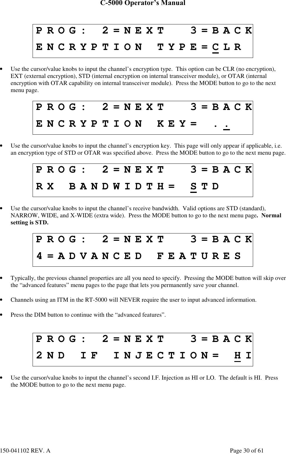
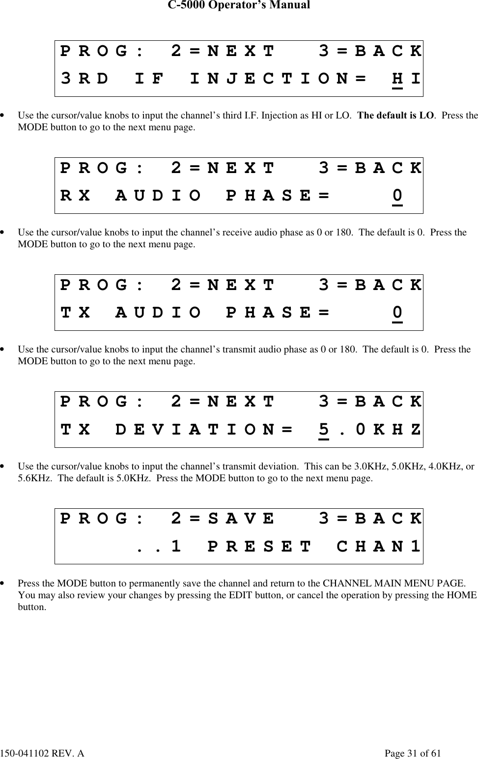
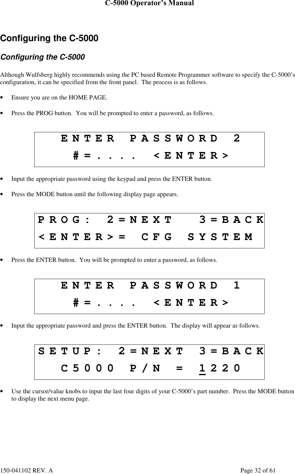
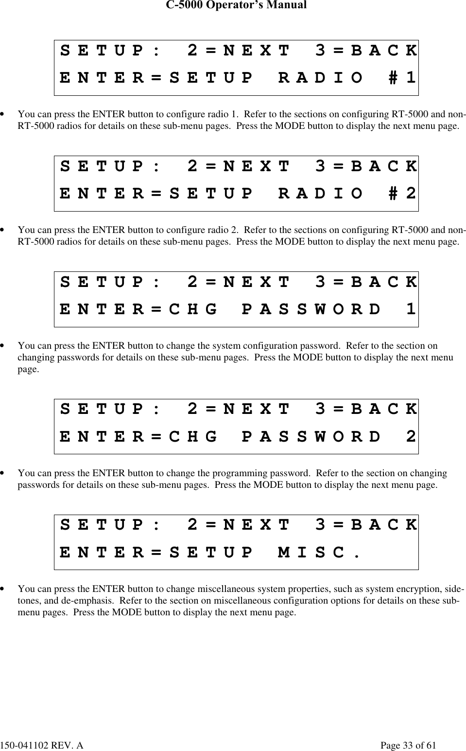
- 1. Operators Manual
- 2. Installation Manual A size pages
- 3. Installation Manual B size pages
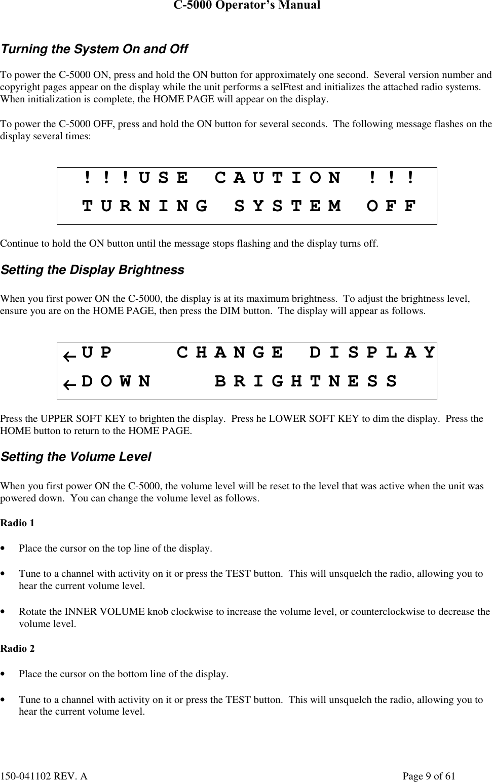
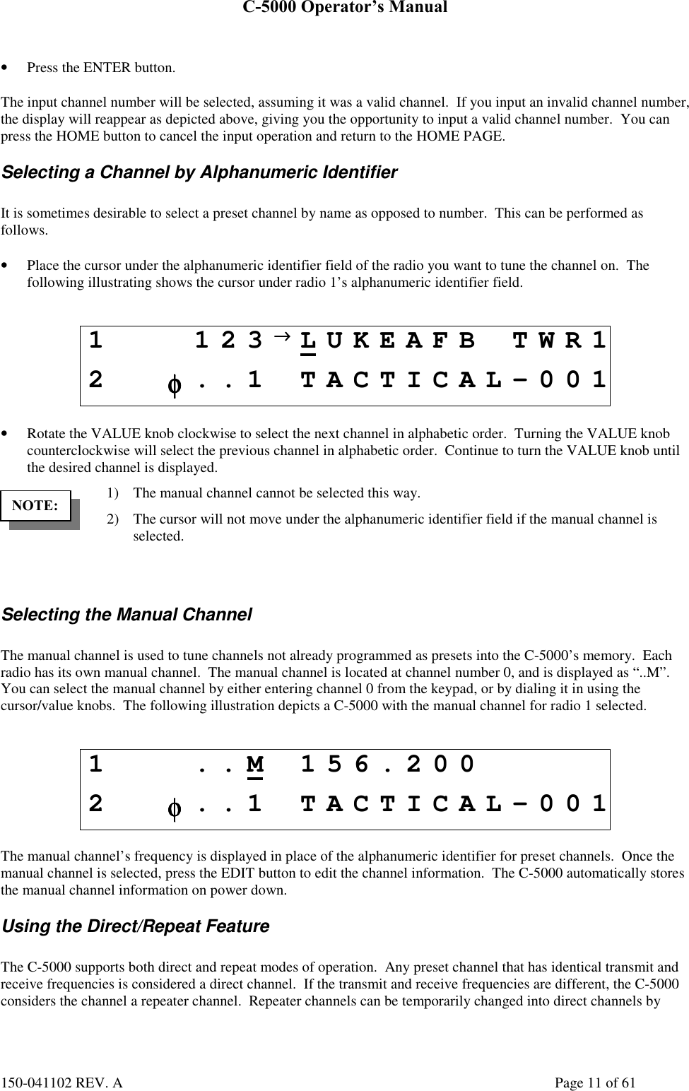
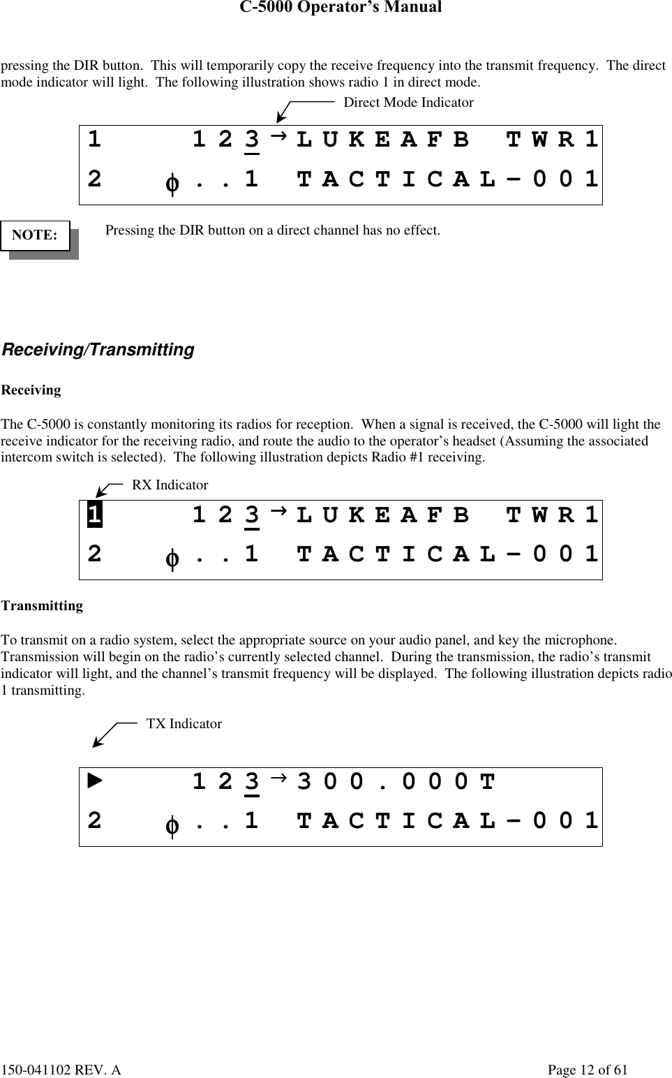
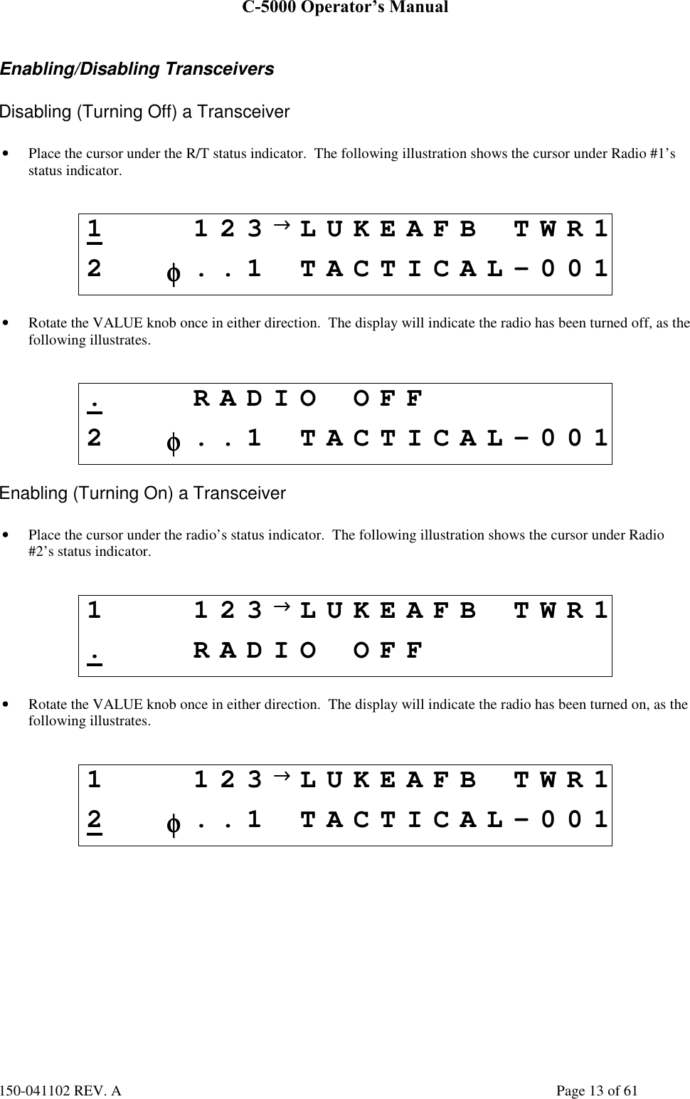
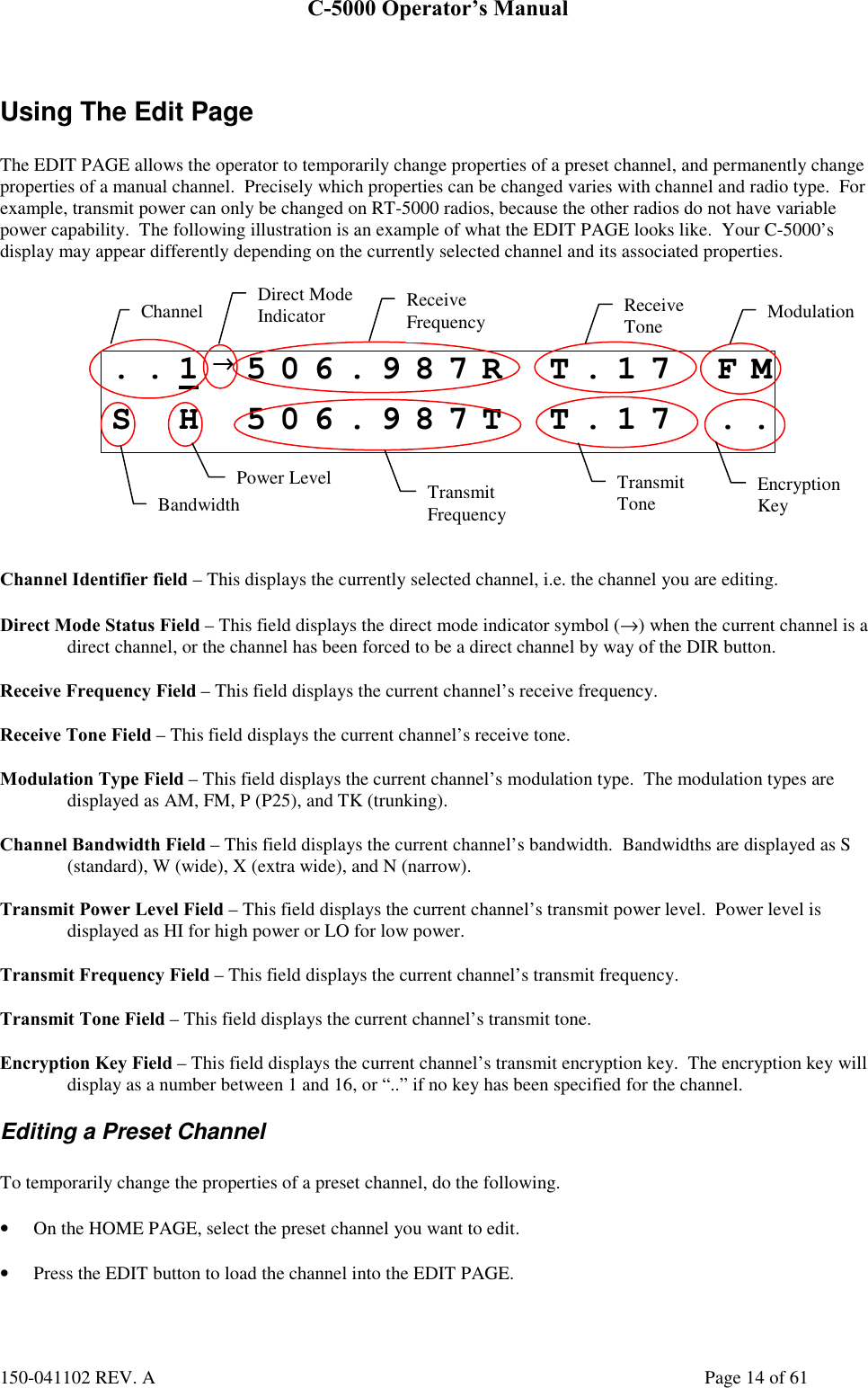
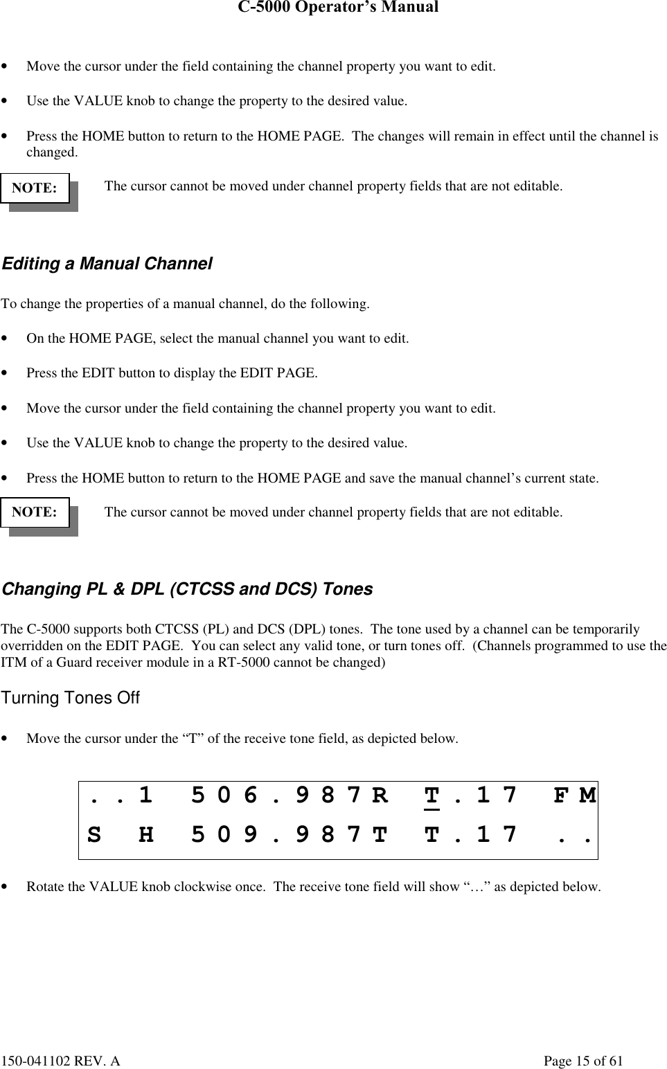
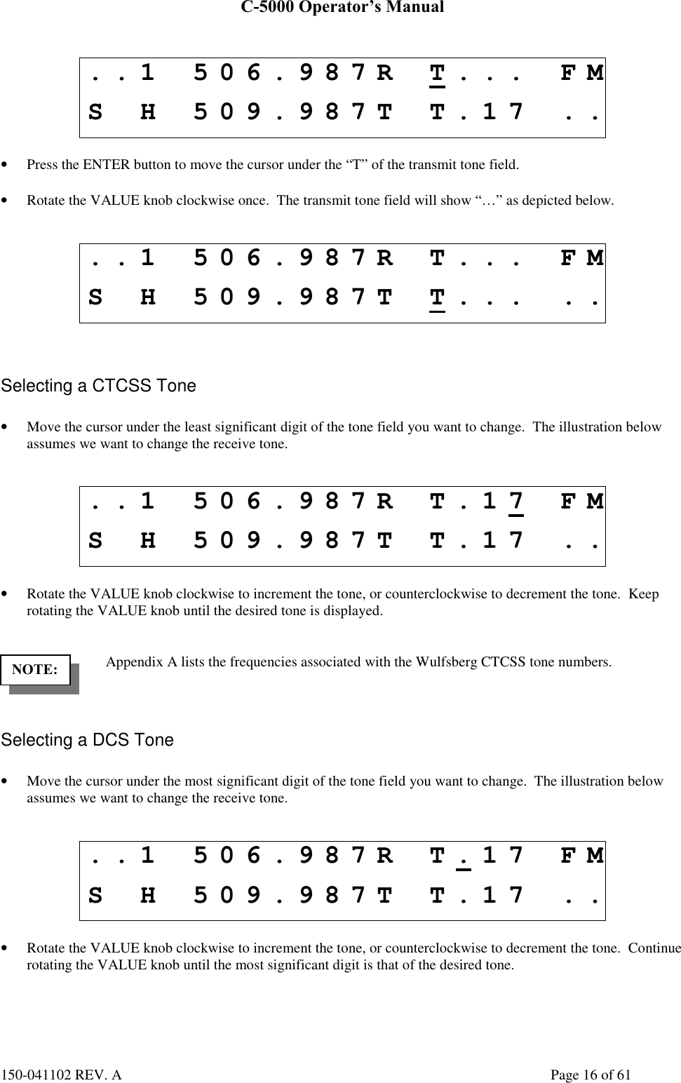
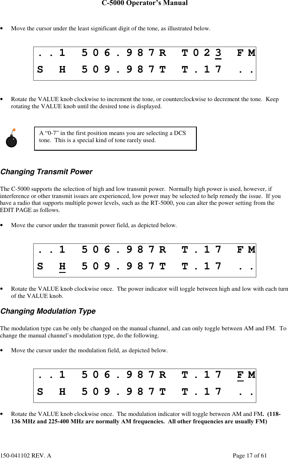
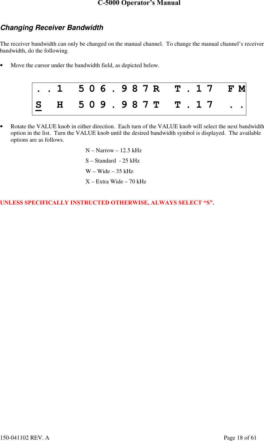
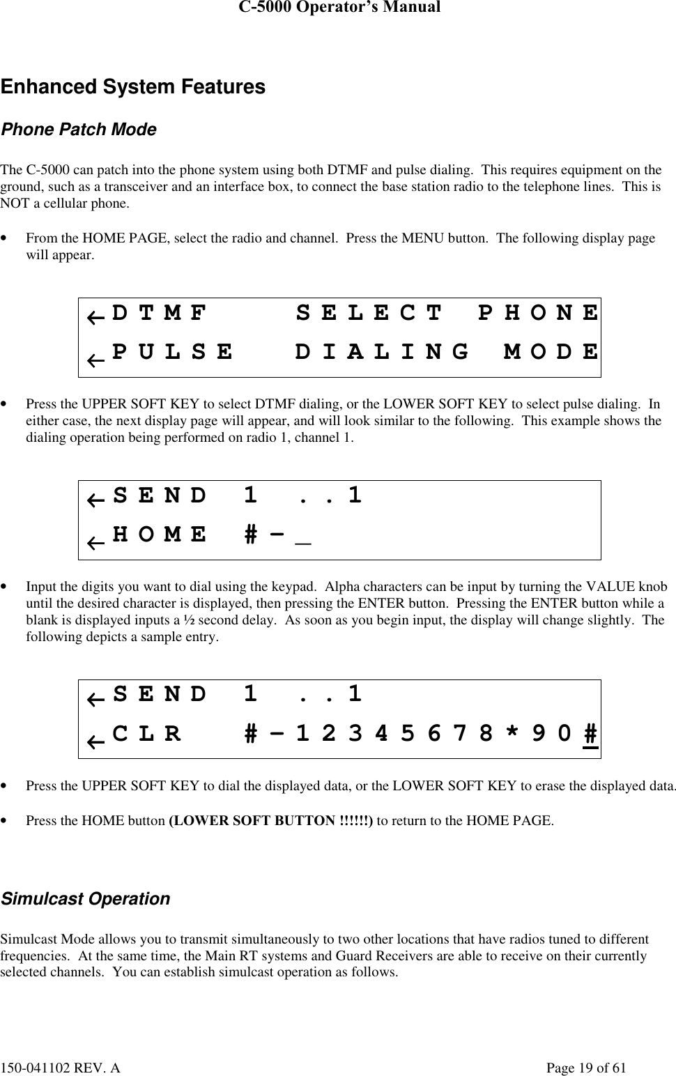
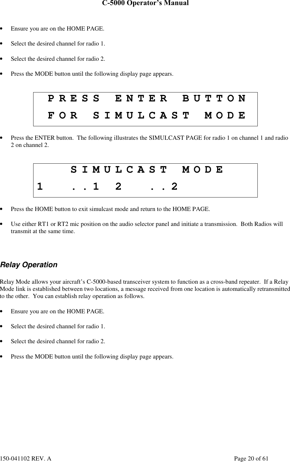
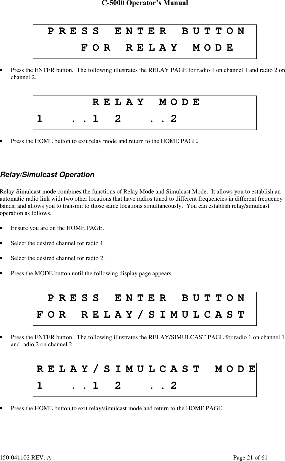
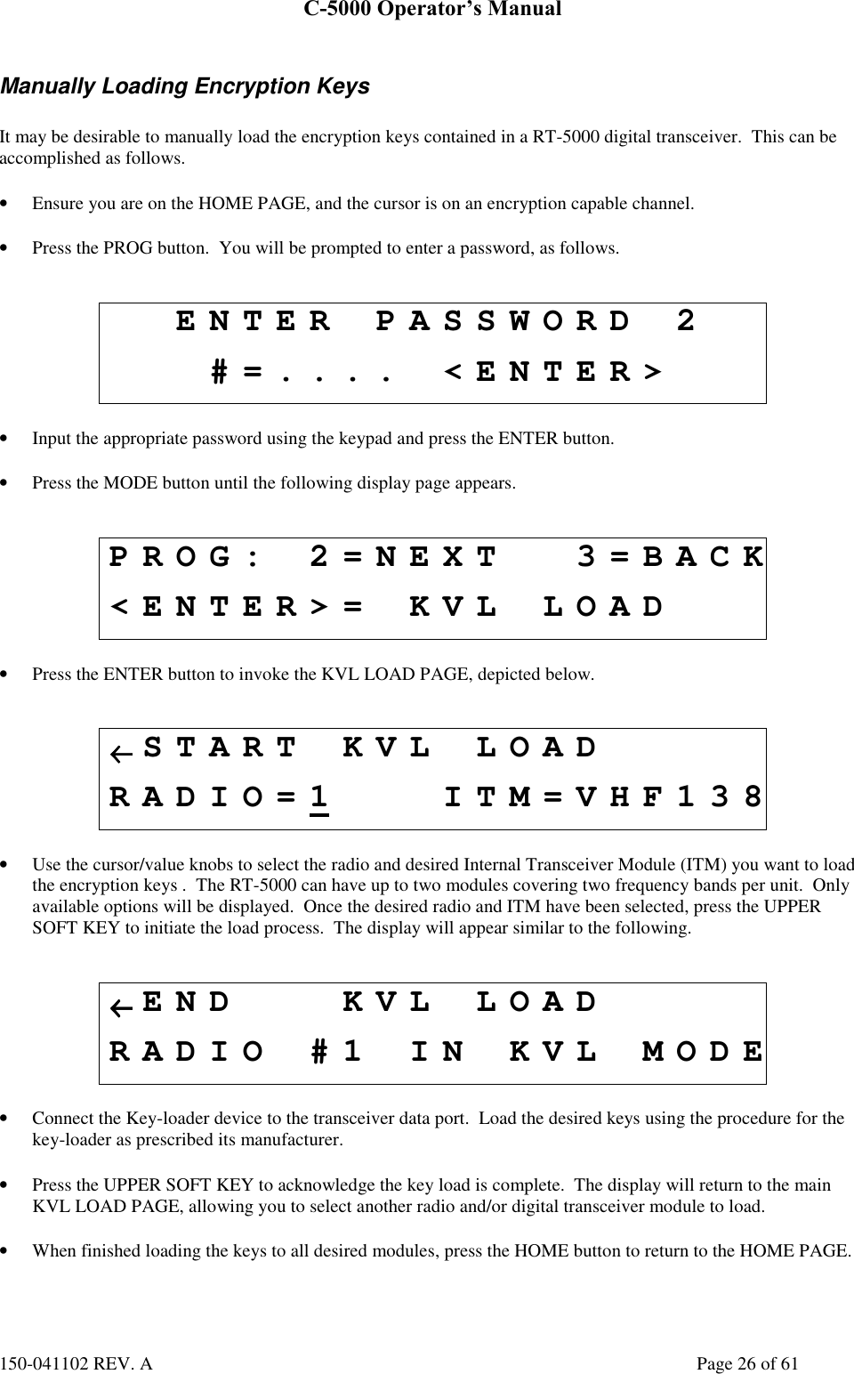
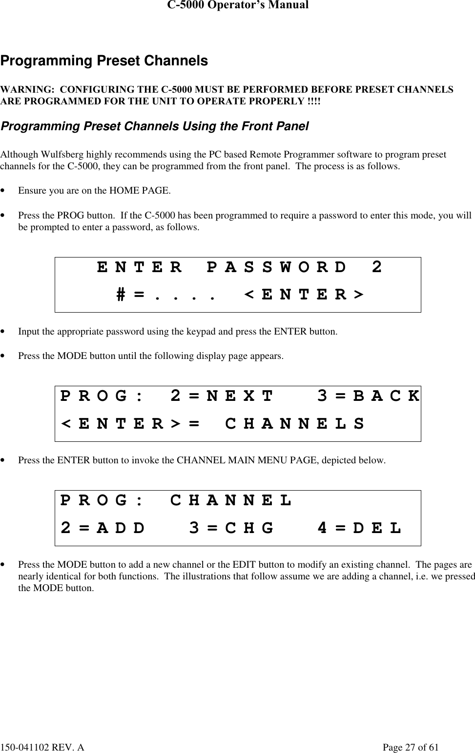
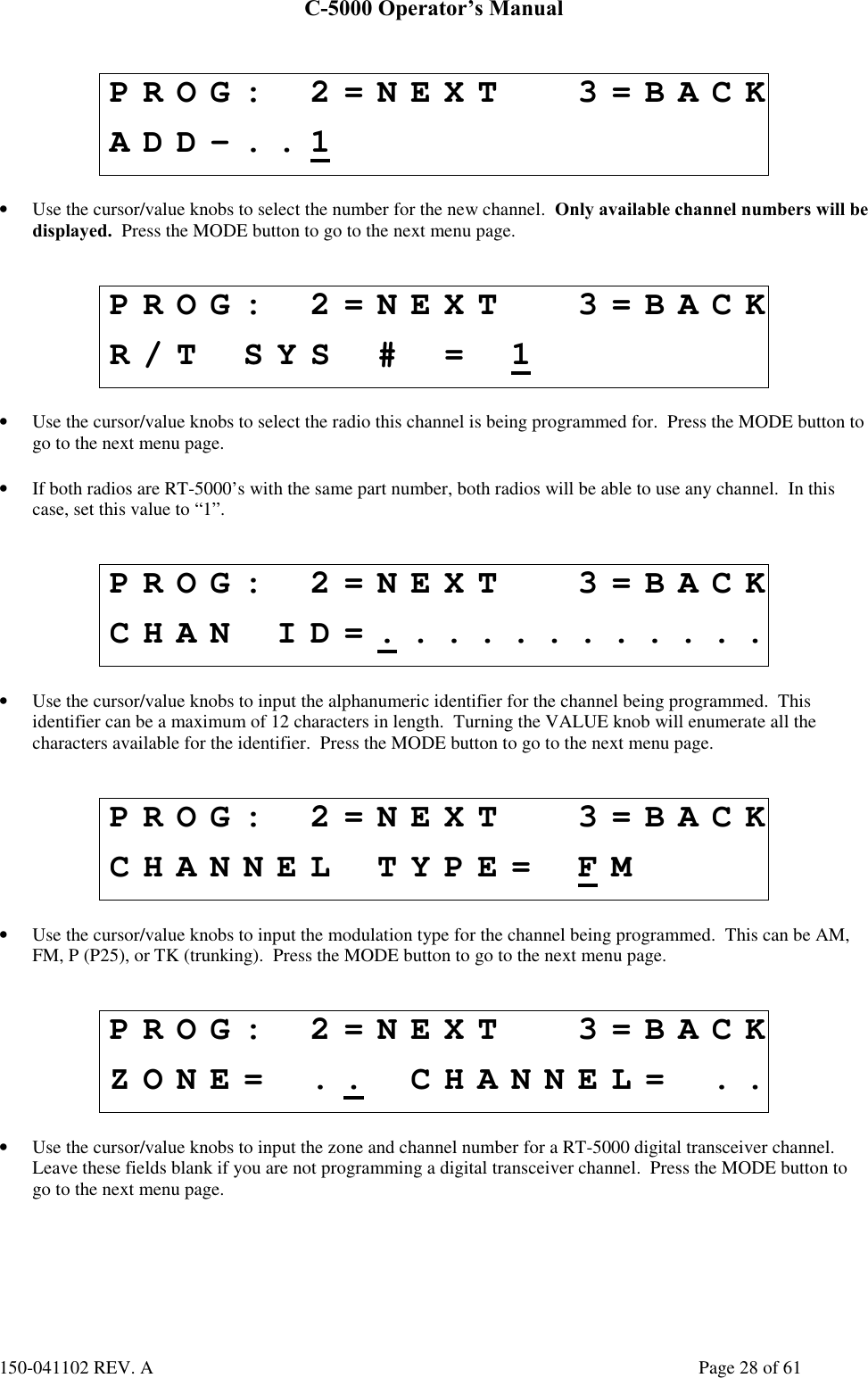
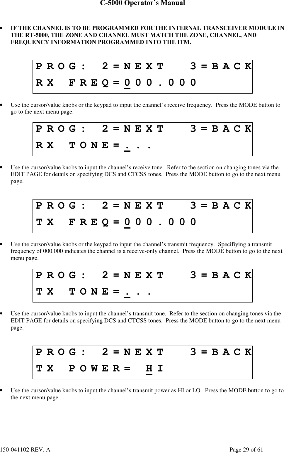
Operators Manual