Wulfsberg Electronics Division RT-5000 RT-5000 Aircraft Transceiver User Manual Installation Manual A size pages
Wulfsberg Electronics Division RT-5000 Aircraft Transceiver Installation Manual A size pages
Contents
- 1. Operators Manual
- 2. Installation Manual A size pages
- 3. Installation Manual B size pages
Installation Manual A size pages

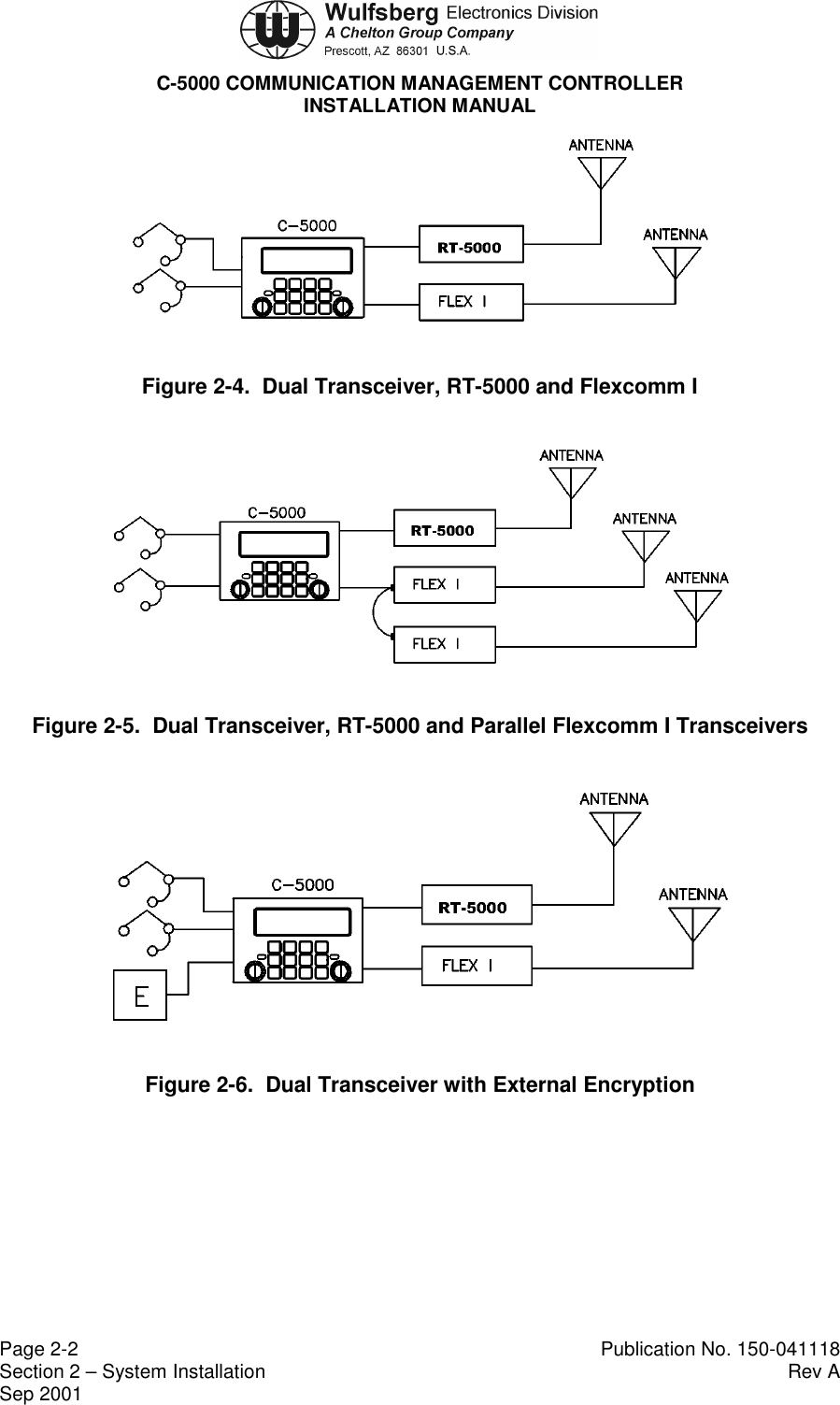
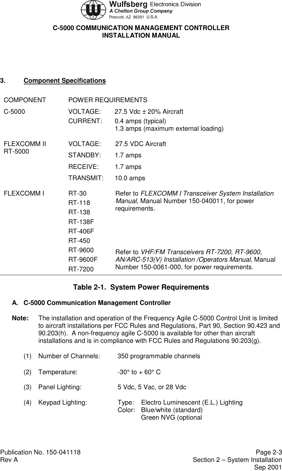
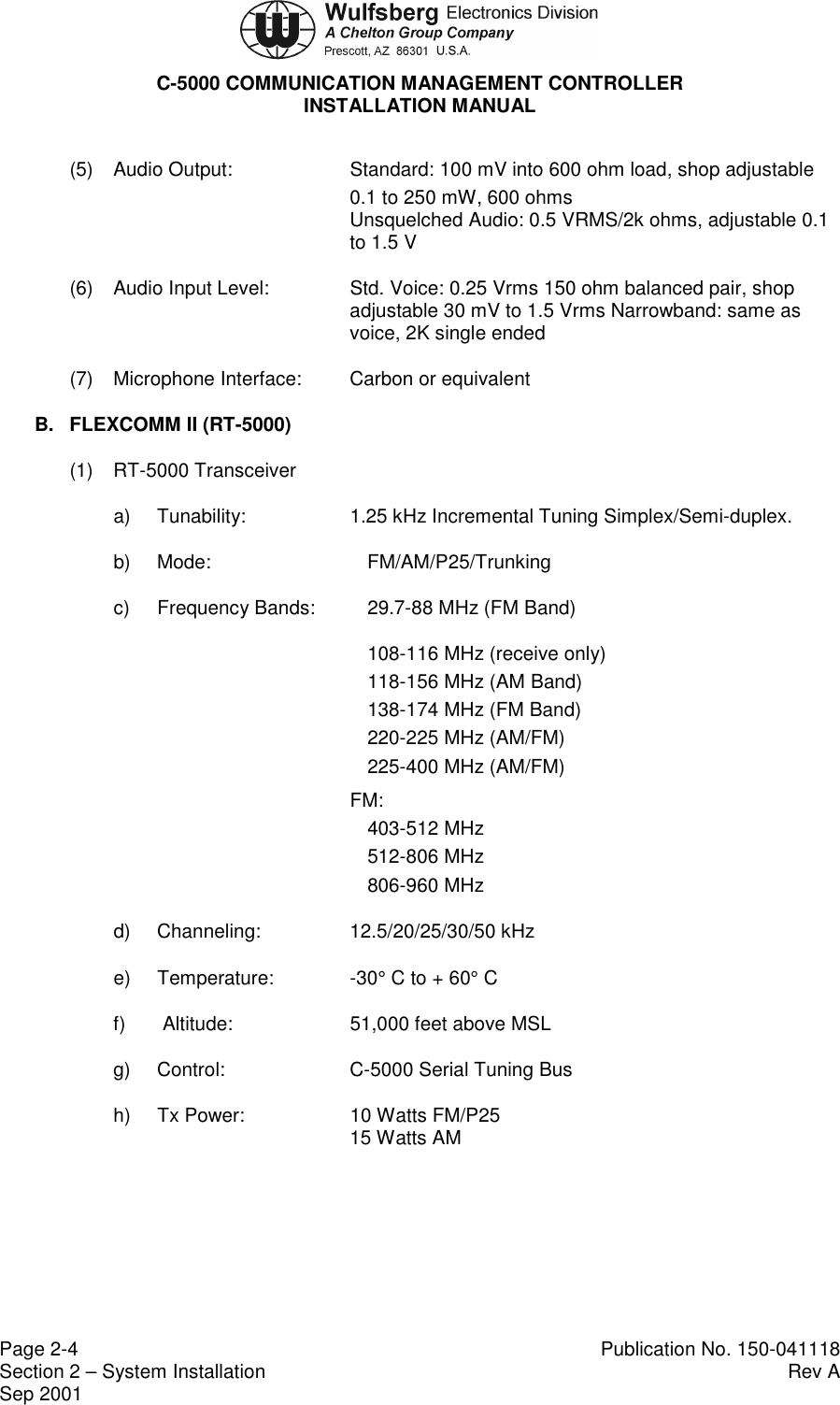

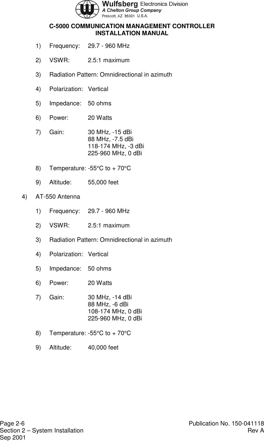
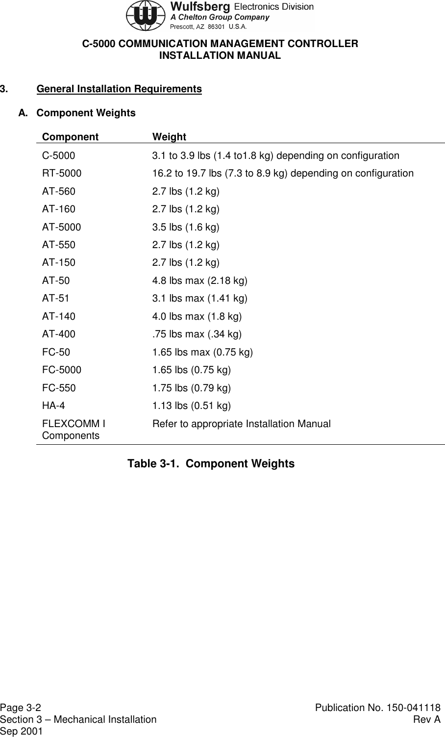
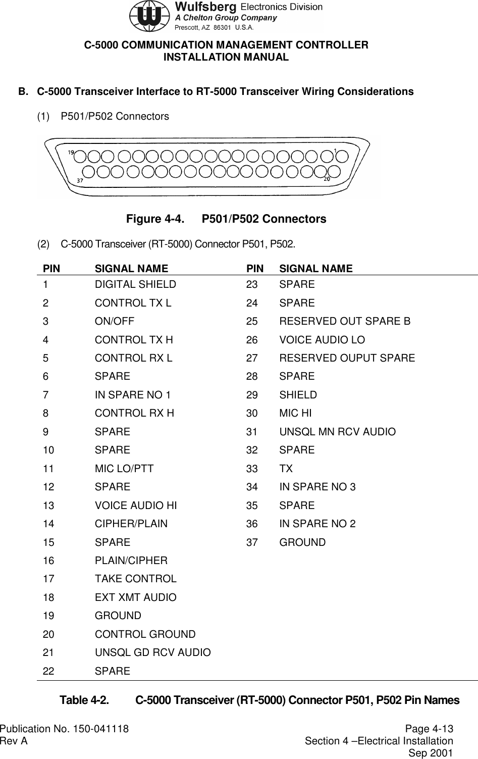
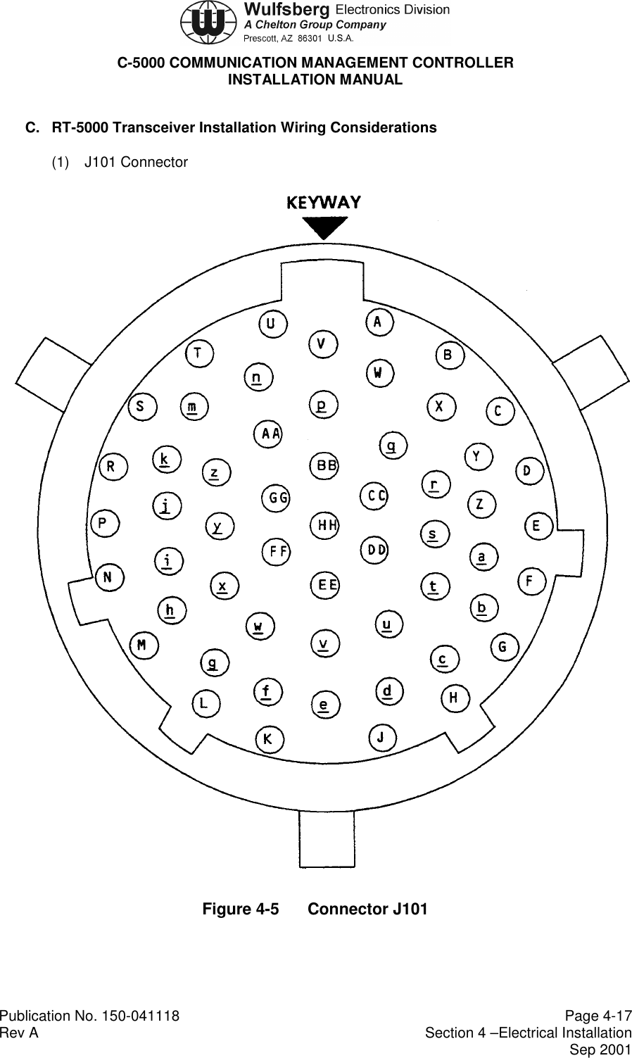
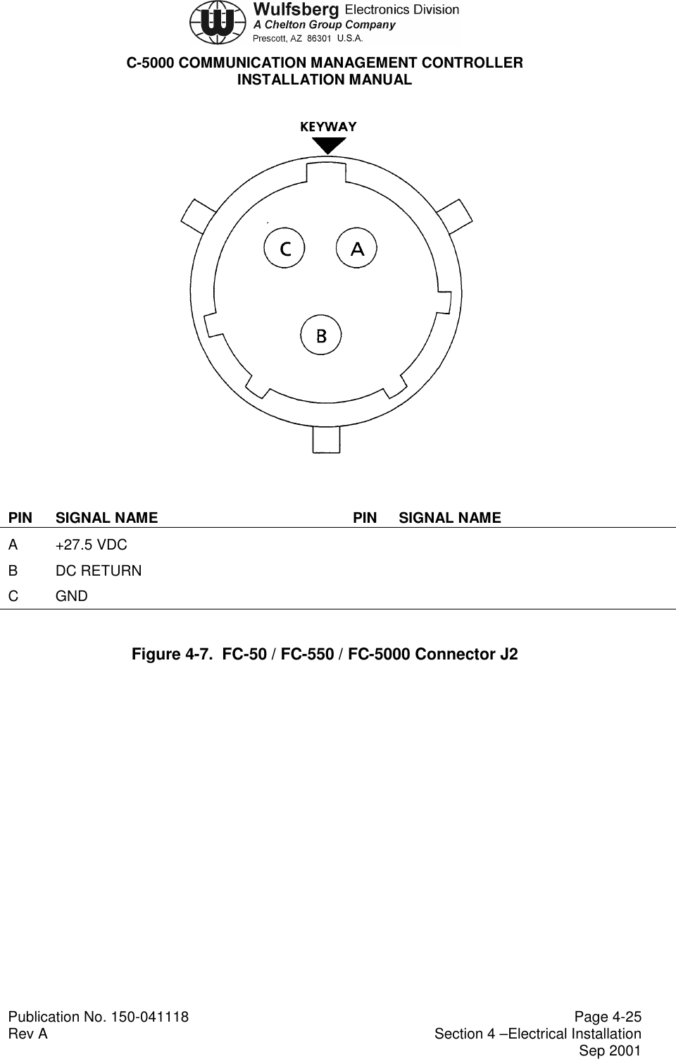
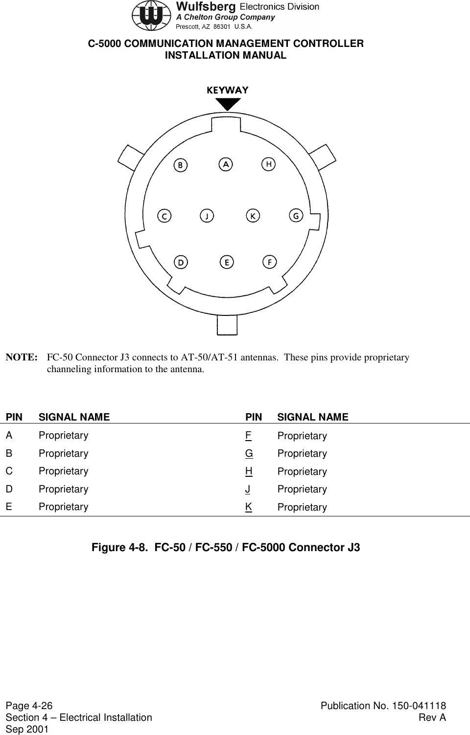
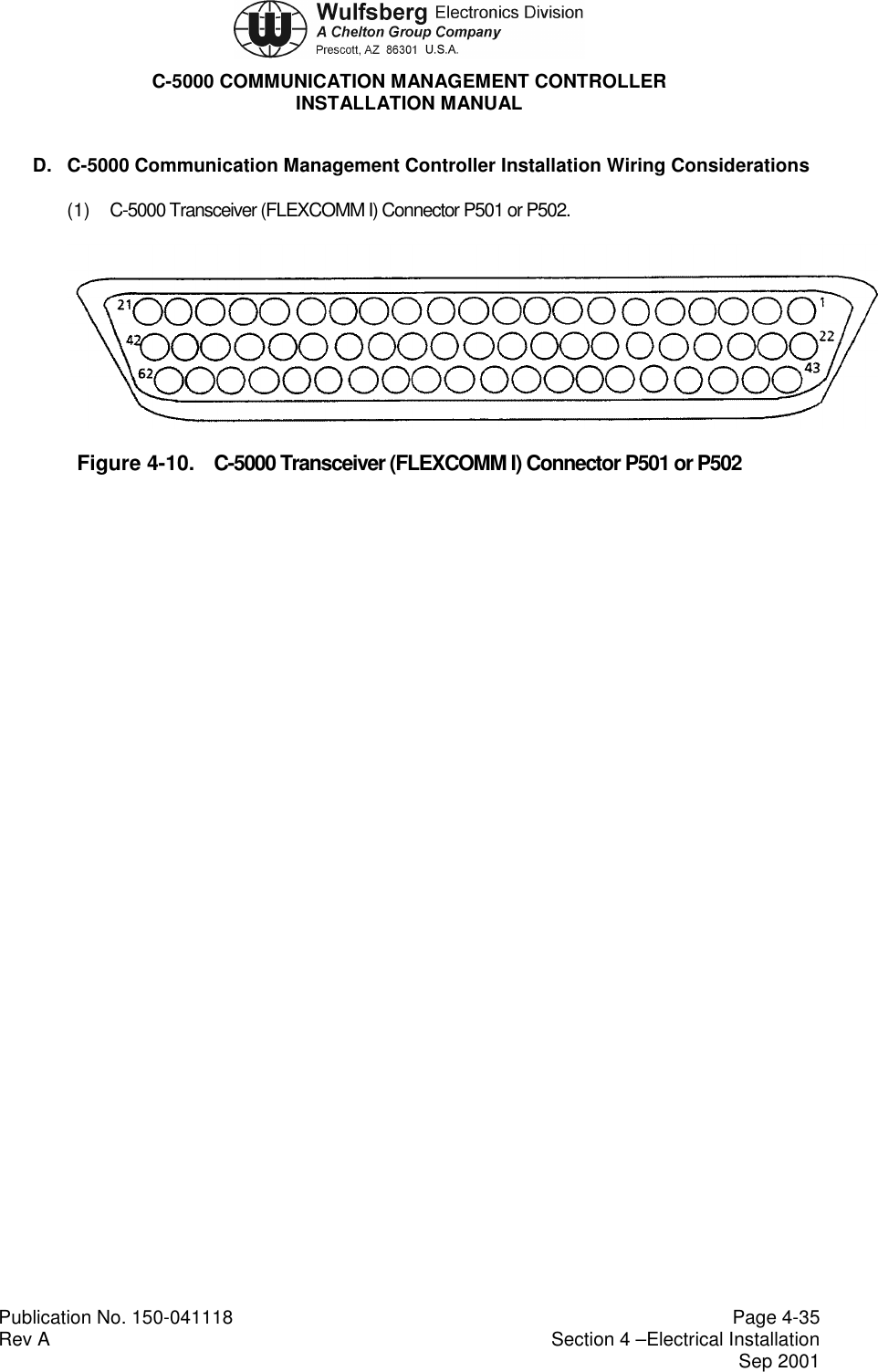
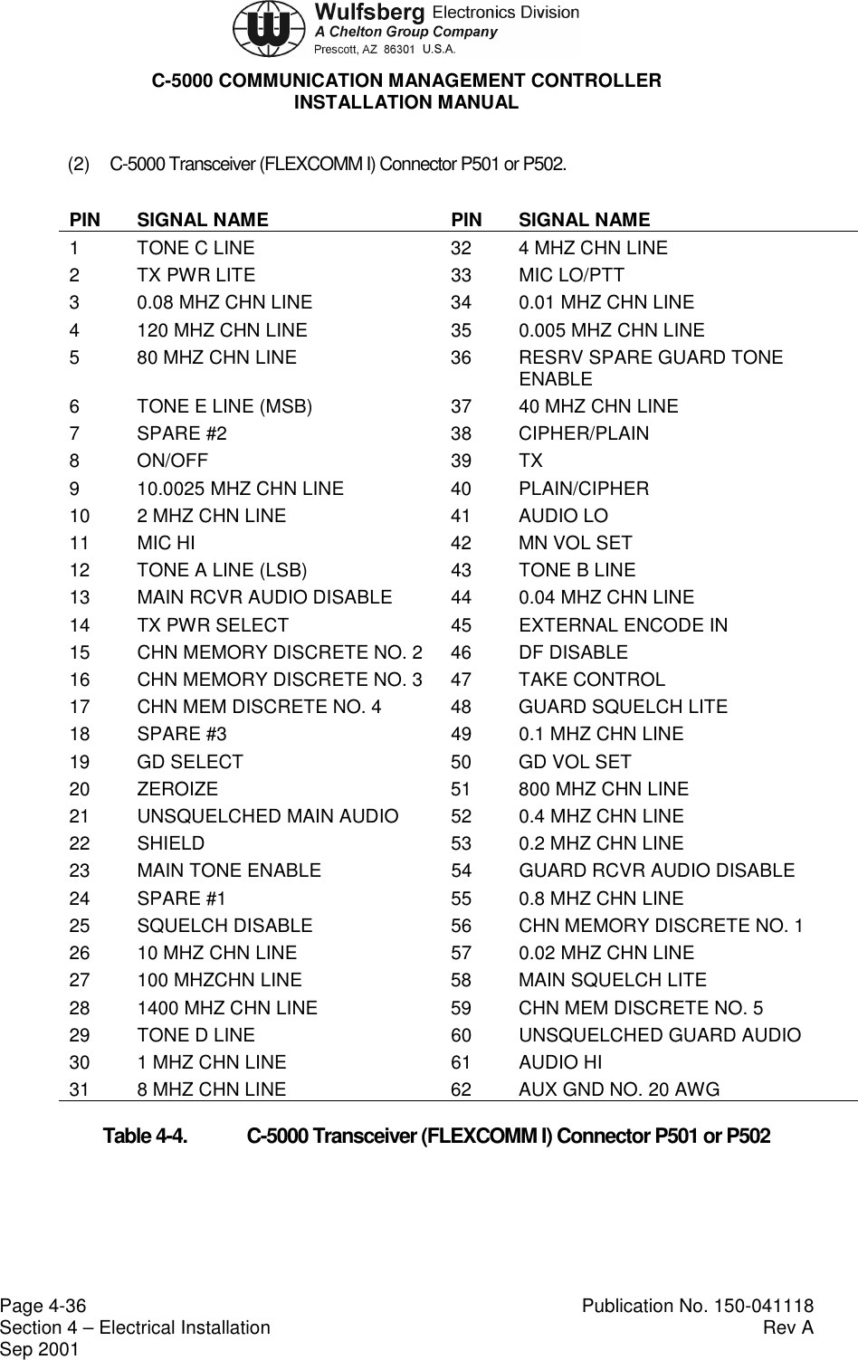
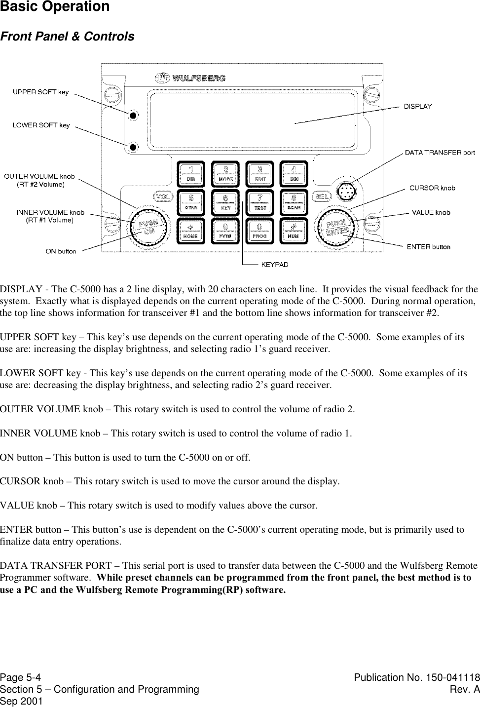
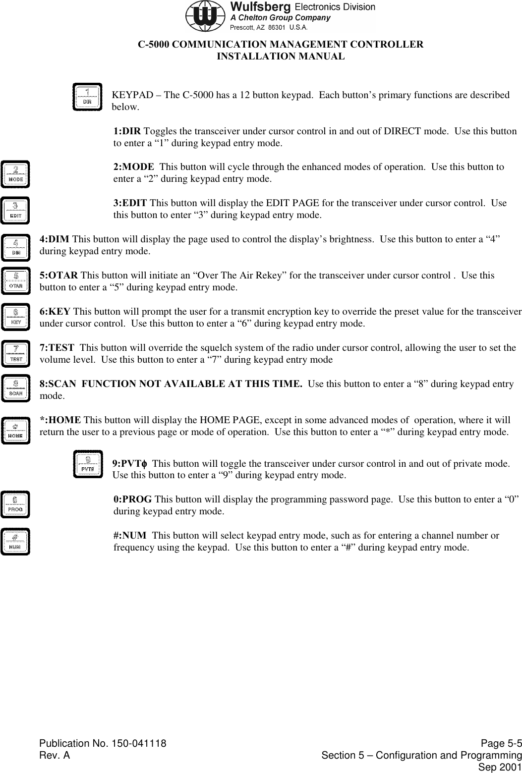
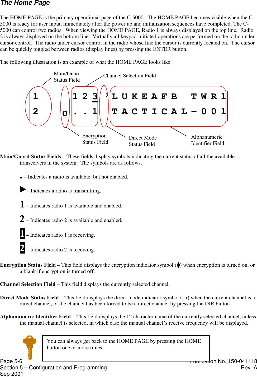
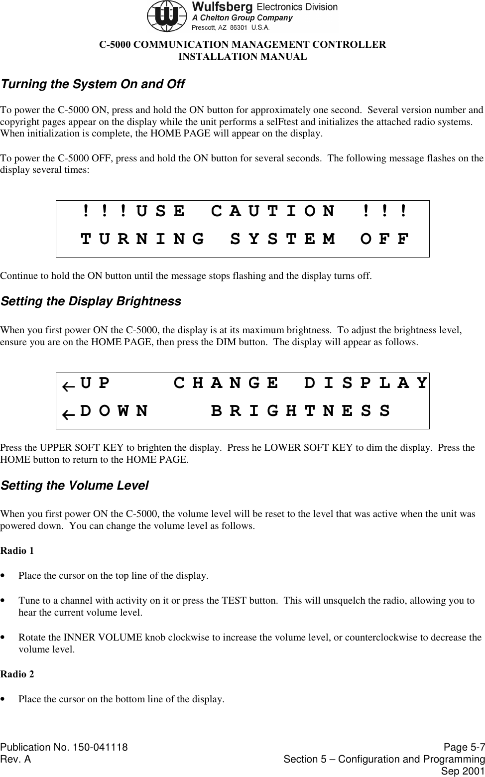
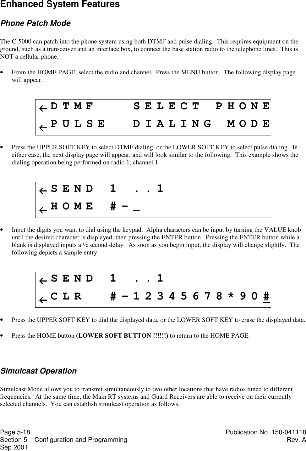
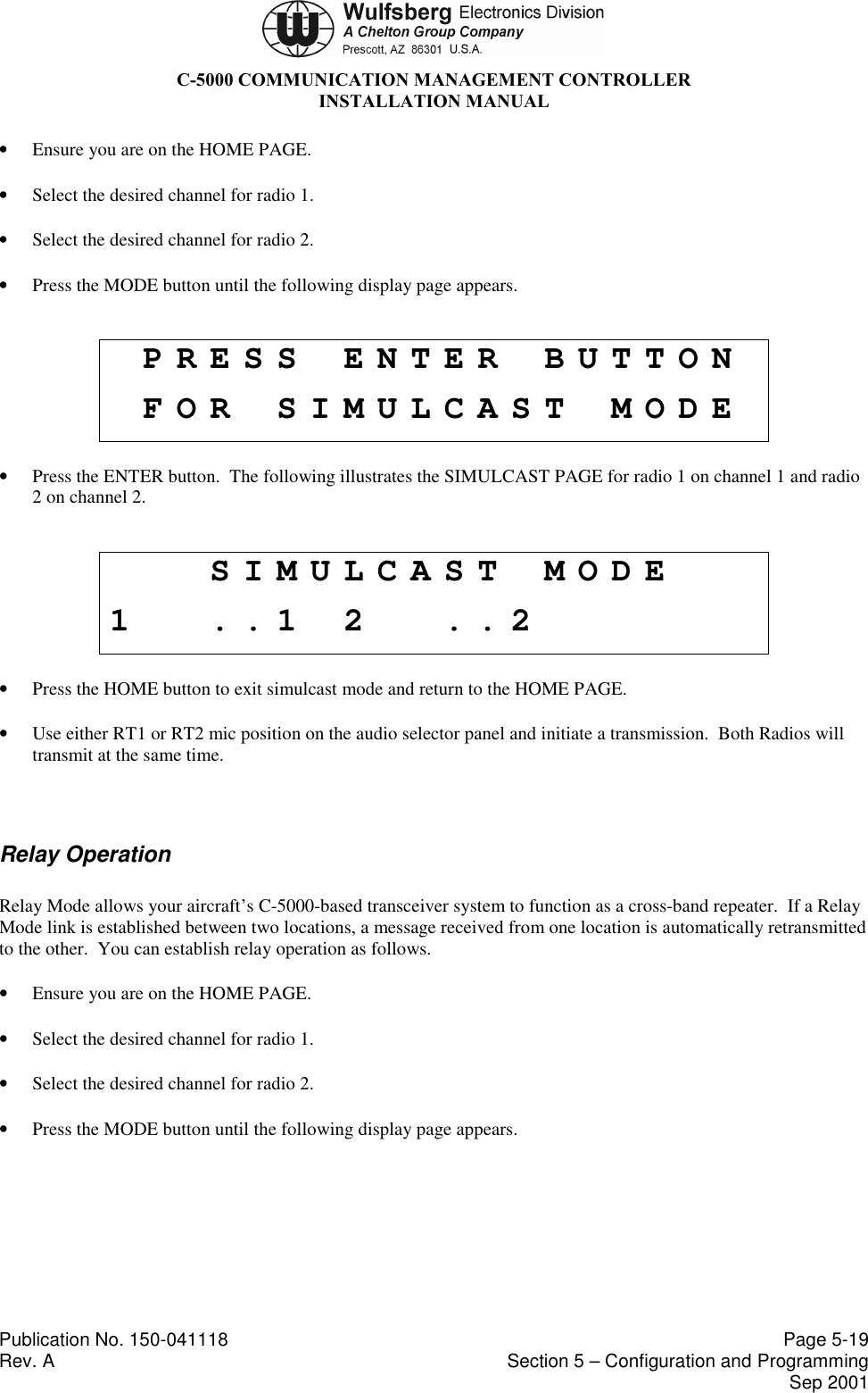
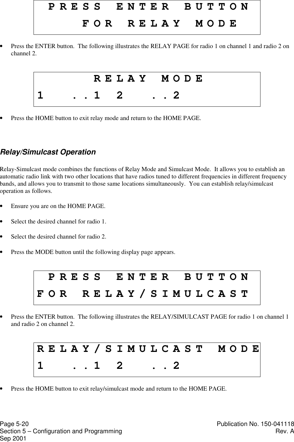
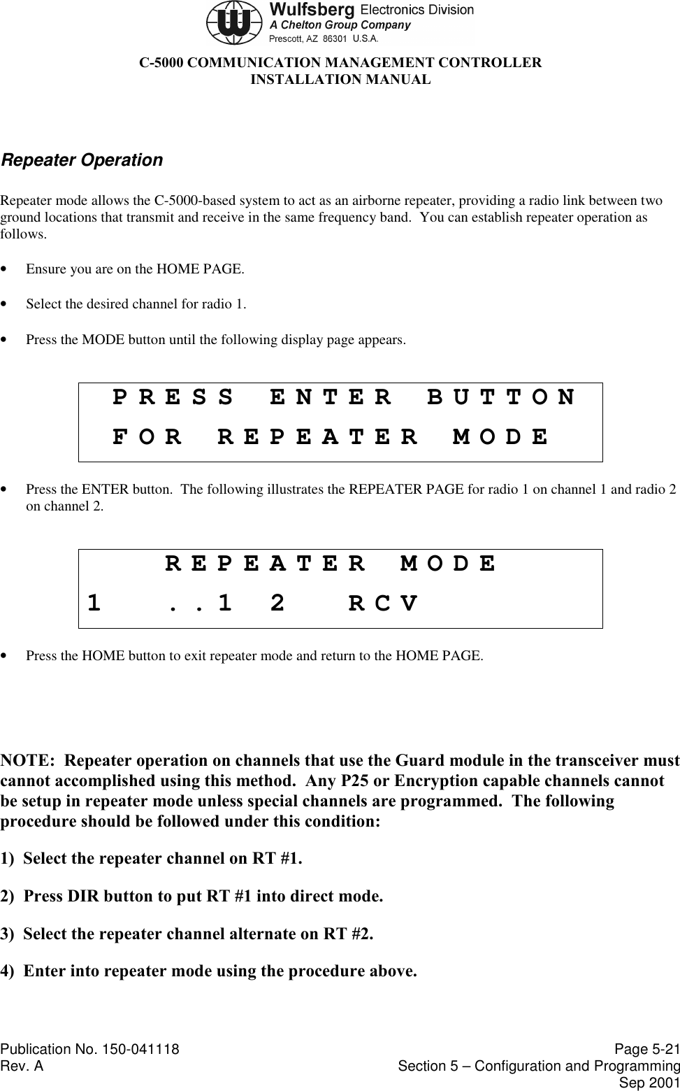
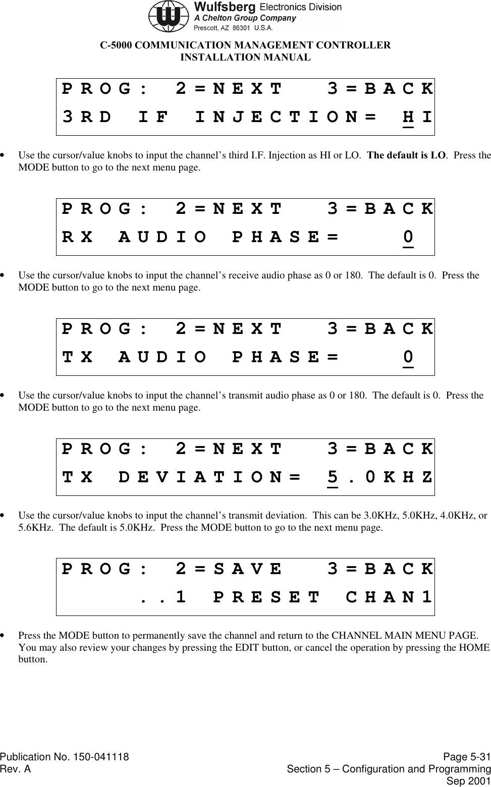
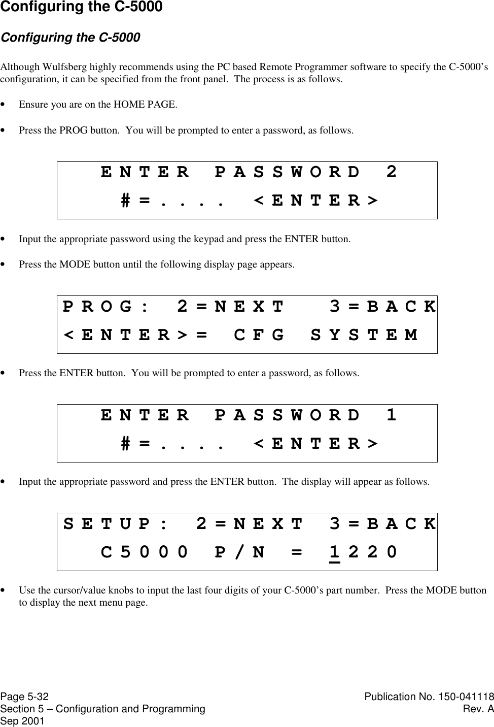
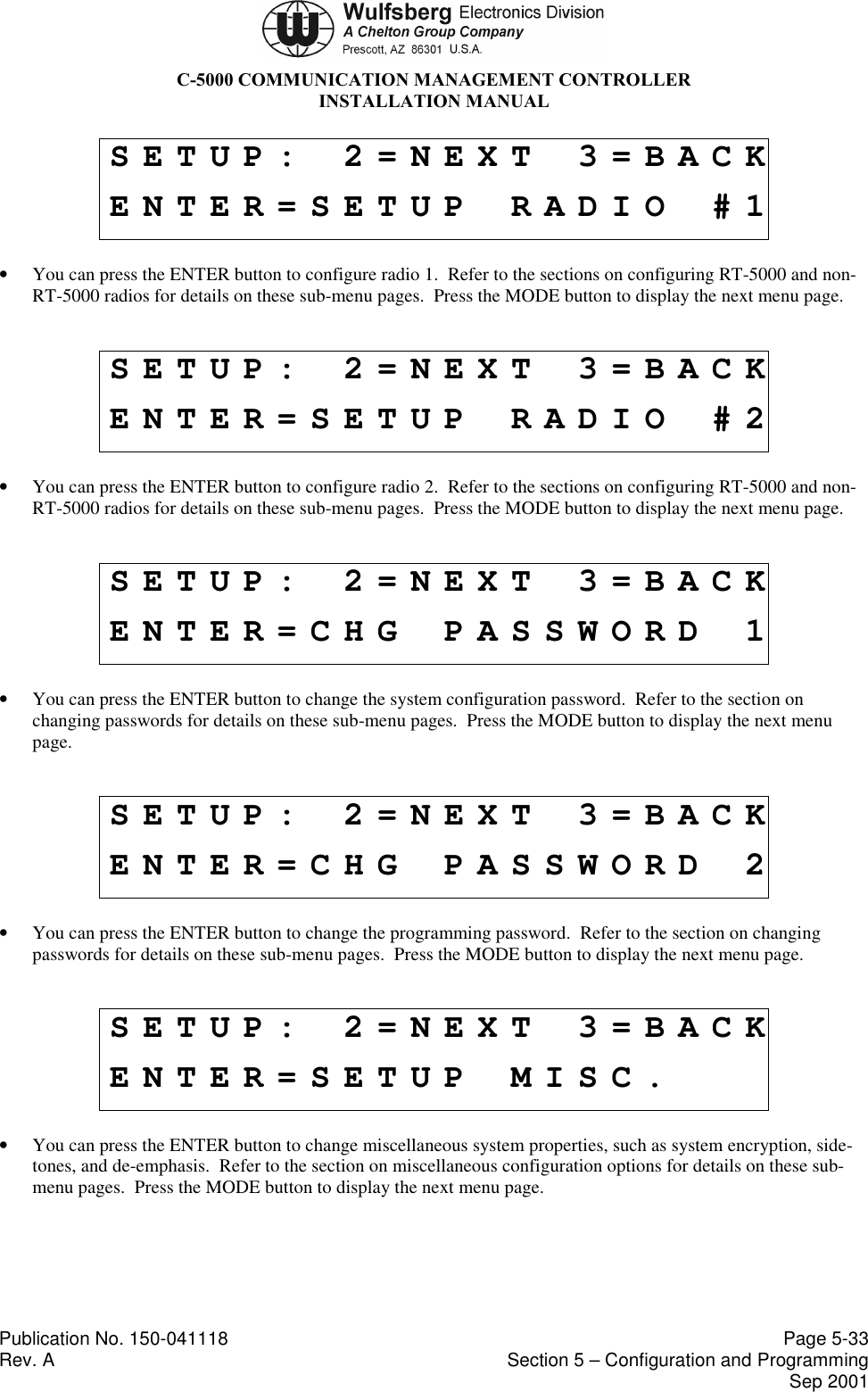
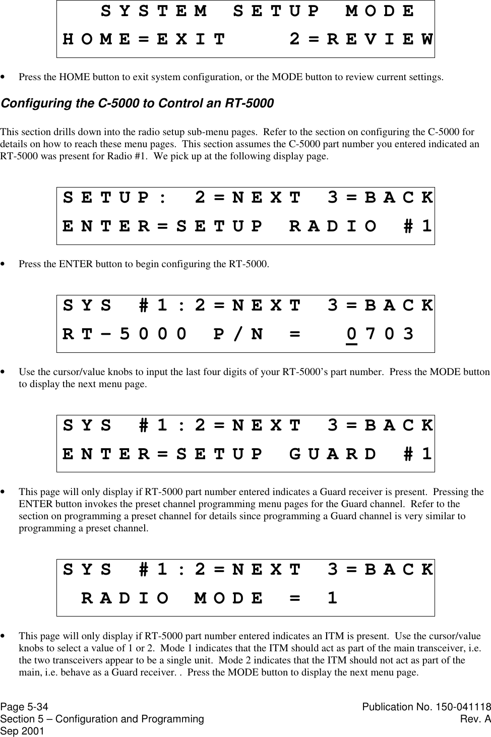
![C-5000 COMMUNICATION MANAGEMENT CONTROLLERINSTALLATION MANUALPublication No. 150-041118 Page 3-3Rev A Section 3 – Mechanical InstallationSep 20014. Installation of Multipin Crimp ConnectorsA. Contacts and Crimp Tool InformationContacts, D-Sub, Min.Crimp or Solder WED PN 129-115451-01Positronic PN FC8122D, crimp (or equivalent) orPositronic FS8122D, solder (or equivalent)Crimp Tools(Suggested supplier:Daniels ManufacturingCorporation526 Thorpe RoadOrlando, FL 32824)C-5000 Serial RT Card interface ConnectorHandle - M22520/2-01Positioner - M22520/2-08C-5000 Parallel RT Card Interface ConnectorHandle - M22520/2-01Positioner - M22520/2-06RT-5000 Interface ConnectorTool Frame - M22520/1-01Turret - M22520/1-02Positioner - M22520/2-08Insertion/Removal Tool Positronic M81969/1-04 or equivalentB. Contacts and Insertion/Removal Tool Manufacturer Name and Address:Positronic Industries, Inc.423 N. Campbell Ave.PO Box 8247Springfield, Missouri 658015. Installation of C-5000Mount C-5000 on Dzus/rails per MIL MS-25213.See Figure 3-1 for mounting dimensions.6. Installation of RT-5000The RT-5000 is designed for horizontal or vertical fixed tray mounting. However, verticalmounting results in better cooling. A minimum of 1 inch clearance is required on allsides.1. Firmly hand-tighten the rack knobs to secure the RT-5000 in the mounting tray. SeeFigures 3-2 through 3-4 for mounting dimensions.2. Attach antenna cabling [Connector J103 (N Type, less-than-or equal-to 400 MHz), andJ102 (TNC Type, greater-than-or-equal-to 400 MHz)]. Insure proper connector mating.3. Attach RT-5000 mating Connector J101 (55 pin).](https://usermanual.wiki/Wulfsberg-Electronics-Division/RT-5000.Installation-Manual-A-size-pages/User-Guide-230673-Page-35.png)