Wulfsberg Electronics Division RT-5000 RT-5000 Aircraft Transceiver User Manual Installation Manual A size pages
Wulfsberg Electronics Division RT-5000 Aircraft Transceiver Installation Manual A size pages
Contents
- 1. Operators Manual
- 2. Installation Manual A size pages
- 3. Installation Manual B size pages
Installation Manual A size pages

C-5000 COMMUNICATION MANAGEMENT CONTROLLER
INSTALLATION MANUAL
Page ii Publication No. 150-041118
Table of Contents Rev A
Sep 2001
Wulfsberg Electronics Division, located in Prescott, Arizona, designs and manufactures the
C-5000 Communication Management Controller
Wulfsberg Electronics Division makes no warranty, expressed or implied, with regard to this
manual, including but not limited to any implied warranties of merchantability, fitness for a
particular purpose, and non-infringement. In addition, Wulfsberg Electronics Division makes no
warranty with regard to the documentation or data contained herein. Wulfsberg Electronics
Division is not liable in the event of incidental, special, consequential, or any other damages in
connection with or arising from furnishing, performance, or use of this manual.
Reproduction of this publication or any portion thereof by any means is prohibited. For further
information contact Sales, Wulfsberg Electronics Division, 6400 Wilkinson Drive, Prescott,
Arizona, 86301. Telephone: (928) 708-1500.
Information in this manual is subject to change without notice.
2001 Wulfsberg Electronics Division. All rights reserved
C-5000 is a trademark of Wulfsberg Electronics Division.
PROPRIETARY NOTICE
This document contains proprietary information and such information may not be disclosed to
others for any purpose, nor used for manufacturing purposes without written permission from
Wulfsberg Electronics Division.

C-5000 COMMUNICATION MANAGEMENT CONTROLLER
INSTALLATION MANUAL
Publication No. 150-041118 Page iii
Rev A Table of Contents
Sep 2001
Record of Revisions
Rev
No. Rev
Date Date
Inserted By Rev
No. Rev
Date Date
Inserted By
A9/2001

C-5000 COMMUNICATION MANAGEMENT CONTROLLER
INSTALLATION MANUAL
Page iv Publication No. 150-041118
Table of Contents Rev A
Sep 2001
Record of Revisions
Rev
No. Rev
Date Date
Inserted By Rev
No. Rev
Date Date
Inserted By

C-5000 COMMUNICATION MANAGEMENT CONTROLLER
INSTALLATION MANUAL
Publication No. 150-041118 Page v
Rev A Table of Contents
Sep 2001
TABLE OF CONTENTS
Page
Section 1 - Introduction
1. Using This Manual...................................................................................................... 1-1
2. Components ............................................................................................................... 1-2
A. Communication Management Controller....................................................... 1-2
B. FLEXCOMM II ............................................................................................... 1-2
C. FLEXCOMM I ................................................................................................ 1-3
D. Part Numbering.............................................................................................. 1-4
Section 2 - System Installation
1. General .......................................................................................................................2-1
2. System Specifications................................................................................................. 2-1
A. C-5000 Communication Management Controller.......................................... 2-1
B. FLEXCOMM II ............................................................................................... 2-2
C. FLEXCOMM I ................................................................................................ 2-8
3. System Interface......................................................................................................... 2-9
A. C-5000 Control Unit/FLEXCOMM II RT System Interface .......................... 2-10
B. C-5000 Control Unit/FLEXCOMM I RT System Interface ........................... 2-11
C. C-5000 Control Unit/Hybrid FLEXCOMM II/FLEXCOMM I Interface .......... 2-12
4. System Operational Modes ...................................................................................... 2-13
A. Single Channel Normal Operation............................................................... 2-13
B. Simulcast Operation .................................................................................... 2-13
C. Relay Operation........................................................................................... 2-13
D. Relay with Simulcast Operation................................................................... 2-13
E. Repeater Operation ..................................................................................... 2-13
F. Dual C-5000 Operation................................................................................ 2-13

C-5000 COMMUNICATION MANAGEMENT CONTROLLER
INSTALLATION MANUAL
Page vi Publication No. 150-041118
Table of Contents Rev A
Sep 2001
TABLE OF CONTENTS (cont’d)
Page
SECTION 3 – MECHANICAL INSTALLATION
1. General .......................................................................................................................3-1
2. Unpacking and Inspecting Equipment........................................................................ 3-1
3. General Installation Requirements ............................................................................. 3-2
A. Component Weights ...................................................................................... 3-2
4. Installation of Multipin Crimp Connectors................................................................... 3-3
A. Contacts and Crimp Tool Information............................................................ 3-3
B. Contacts and Insertion/Removal Tool Manufacturer Name and Address..... 3-3
5. Installation of C-5000.................................................................................................. 3-3
6. Installation of RT-5000................................................................................................ 3-3
7. Installation of Antennas .............................................................................................. 3-4
A. AT-560 / AT-5000 .......................................................................................... 3-4
B. FC-50............................................................................................................. 3-4
C. AT-550 ........................................................................................................... 3-4
D. FC-5000......................................................................................................... 3-4
E. AT-50 and AT-51 ........................................................................................... 3-4
F. FC-50............................................................................................................. 3-5
G. AT-400 ........................................................................................................... 3-5
H. AT-140 ........................................................................................................... 3-5
SECTION 4 - ELECTRICAL INSTALLATION
1. General .......................................................................................................................4-1
2. Wiring Considerations................................................................................................. 4-1
A. C-5000 System Interface Connector, P500................................................... 4-2
B. C-5000 Transceiver Interface, RT-5000...................................................... 4-13
C. RT-=5000 Transceiver Installation .............................................................. 4-17
D. C-5000 Communication Management Controller Installation...................... 4-35
E. C-5000 Transceiver Interface FLEXCOMM................................................. 4-37
F. C-5000 Transceiver Interface...................................................................... 4-47

C-5000 COMMUNICATION MANAGEMENT CONTROLLER
INSTALLATION MANUAL
Publication No. 150-041118 Page vii
Rev A Table of Contents
Sep 2001
TABLE OF CONTENTS (cont’d)
Page
SECTION 5 – CONFIGURATION AND PROGRAMMING
Introduction .............................................................................................................................. 5-1
Features...................................................................................................................... 5-1
Transceiver Overview................................................................................................. 5-1
Steps to Successful Setup and Operation.................................................................. 5-3
Basic Operation ....................................................................................................................... 5-4
Front Panel & Controls ............................................................................................... 5-4
The Home Page.......................................................................................................... 5-6
Turning the System On and Off.................................................................................. 5-7
Setting the Display Brightness.................................................................................... 5-7
Setting the Volume Level............................................................................................ 5-7
Selecting a Preset Channel Using the Cursor/Value Knob ........................................ 5-8
Selecting a Channel Using the Keypad...................................................................... 5-8
Selecting a Channel by Alphanumeric Identifier......................................................... 5-9
Selecting the Manual Channel.................................................................................... 5-8
Using the Direct/Repeat Feature.............................................................................. 5-10
Receiving/Transmitting ............................................................................................. 5-10
Enabling/Disabling Transceivers .............................................................................. 5-11

C-5000 COMMUNICATION MANAGEMENT CONTROLLER
INSTALLATION MANUAL
Page viii Publication No. 150-041118
Table of Contents Rev A
Sep 2001
TABLE OF CONTENTS (cont’d)
Page
SECTION 5 –CONFIGURATION AND PROGRAMMING (cont’d)
Disabling (Turning Off) a Transceiver.......................................................... 5-11
Enabling (Turning On) a Transceiver .......................................................... 5-11
Using the Edit Page............................................................................................................... 5-13
Editing a Preset Channel.......................................................................................... 5-13
Editing a Manual Channel......................................................................................... 5-14
Changing PL and DPL (CTCSS and DCS) Tones ................................................... 5-14
Turning Tones Off........................................................................................ 5-14
Selecting a CTCSS Tone ............................................................................ 5-15
Selecting a DCS Tone................................................................................. 5-15
Changing Transmit Power ........................................................................................ 5-16
Changing Modulation Type....................................................................................... 5-16
Changing Receiver Bandwidth ................................................................................. 5-17
Enhanced System Features .................................................................................................. 5-18
Phone Patch Mode ................................................................................................... 5-18
Simulcast Operation ................................................................................................. 5-18
Relay Operation........................................................................................................ 5-19
Relay/Simulcast Operation ....................................................................................... 5-20
Repeater Operation .................................................................................................. 5-21
Encryption Features............................................................................................................... 5-22
Turning Encryption On and Off................................................................................. 5-22
Selecting an Encryption Key..................................................................................... 5-22
Performing an OTAR ................................................................................................ 5-23
Erasing Encryption Keys........................................................................................... 5-24
Manually Loading Encryption Keys .......................................................................... 5-25
Programming Preset Channels.............................................................................................. 5-27
Programming Preset Channels Using the Front Page ............................................. 5-27

C-5000 COMMUNICATION MANAGEMENT CONTROLLER
INSTALLATION MANUAL
Publication No. 150-041118 Page ix
Rev A Table of Contents
Sep 2001
TABLE OF CONTENTS (cont’d)
Page
SECTION 5 –CONFIGURATION AND PROGRAMMING (cont’d)
Configuring the C-5000..........................................................................................................5-32
Configuring the C-5000............................................................................................. 5-32
Configuring the C-5000 to Control an RT-5000........................................................ 5-34
Configuring the C-5000 to Control a Non RT-5000 .................................................. 5-35
Setting Passwords.................................................................................................... 5-38
Setting Miscellaneous Configuration Options........................................................... 5-39
Configuring the C-5000 Using a PC ......................................................................... 5-40
Downloading a Configuration from RP into the C-5000 .............................. 5-40
Uploading a Configuration from the C-5000 into RP ................................... 5-41
RSS Software Description and Programming ....................................................................... 5-43
Before You Begin...................................................................................................... 5-43
Main Menu Operations ............................................................................................. 5-43
Personality Programming (Conventional Analog FM Personalities) ........................ 5-50
Personality Programming (Conventional P25 Personalities).................................... 5-53
Glossary................................................................................................................................. 5-58
Appendix A – CTCSS (PL) Tone Codes................................................................................ 5-61
Appendix B – Mode 2 Operation............................................................................................ 5-63

C-5000 COMMUNICATION MANAGEMENT CONTROLLER
INSTALLATION MANUAL
Page x Publication No. 150-041118
Table of Contents Rev A
Sep 2001
TABLE OF CONTENTS (cont’d)
Page
SECTION 6 – SYSTEM VERIFICATION PROCEDURE
1. General .......................................................................................................................7-1
2. System Checkout........................................................................................................ 7-1
C-5000 COMMUNICATION MANAGEMENT CONTROLLER
INSTALLATION MANUAL
Publication No. 150-041118 Page 1-1
Rev A Section 1 - Introduction
Sep 2001
SECTION 1 - INTRODUCTION
IMPORTANT
This manual contains information pertaining to the installation of the C-5000
Communication Management Controller with FLEXCOMM II and FLEXCOMM I.
FLEXCOMM II consists of the RT-5000 Transceiver, appropriate antennas, and optional
equipment as required. FLEXCOMM I consists of the RT-9600 Transceiver, RT-9600F
Transceiver, RT-7200 Transceiver, and optional combinations of up to three of the
following FLEXCOMM Transceivers: RT-30, RT-118, RT-138(F), RT-406F, RT-450,
appropriate antennas, and optional equipment as required. The C-5000 can also
interface with combined applications of FLEXCOMM II and FLEXCOMM I, i.e., a hybrid
RT System configuration that consists of both RT-5000 and FLEXCOMM I Transceivers.
1. Using This Manual
This manual is divided into the following sections:
SECTION 1- INTRODUCTION
This section contains an overview of the contents of this manual and lists the components
installed in FLEXCOMM I and FLEXCOMM II systems using the C-5000.
SECTION 2 - SYSTEM INSTALLATION
This section covers the general system characteristics, interface capabilities and power
requirements.
SECTION 3 - MECHANICAL INSTALLATION
This section contains system component dimensions, the racking requirements, weights, and
component installation data.
SECTION 4 - FLEXCOMM II ELECTRICAL INSTALLATION
This section contains the wiring information to install the C-5000 Control Unit with the
FLEXCOMM II Transceiver in an aircraft.
SECTION 5 - FLEXCOMM I ELECTRICAL INSTALLATION
This section contains the wiring information to install the C-5000 Control Unit with the
FLEXCOMM I Transceiver in an aircraft.
SECTION 6 - SYSTEM CONFIGURATION AND PRESET CHANNEL PROGRAMMING
This section contains the system configuration and preset channel programming procedures
for the system.
SECTION 7 - SYSTEM CHECKOUT
This section contains checkout procedure for the system after installation.
C-5000 COMMUNICATION MANAGEMENT CONTROLLER
INSTALLATION MANUAL
Page 1-2 Publication No. 150-041118
Section 1 - Introduction Rev A
Sep 2001
2. Components
The following components can be installed:
A. Communication Management Controller
C-5000 PN 31300-1X02-1XX0 (See Figure 1-1)
B. FLEXCOMM II
(1) Transceivers
RT-5000 PN 400-015525-XXXX (See Table 1-1)
(2) Antennas Systems (Refer to Table 1-2)
AT-560 PN 121-040130-XX
AT-160 PN 121-040129-01
AT-5000 PN 121-040045-01
AT-550 PN 121-017850-01
AT-150 PN 153-017822-01
AT-50 PN 121-016587-01
AT-51 PN 121-016796-01
AT-140 PN 121-016584-01
AT-400 PN 121-16821-01
FC-50 Logic Converter PN 153-016586-01
FC-5000 Logic Converter PN 153-040047-01
FC-550 Logic Converter PN 153-017851
(3) RT-5000 Mounting Trays
Vertical Mounting Tray PN 300-316605-01
Horizontal Mounting Tray PN 300-316835-01

C-5000 COMMUNICATION MANAGEMENT CONTROLLER
INSTALLATION MANUAL
Publication No. 150-041118 Page 1-3
Rev A Section 1 - Introduction
Sep 2001
C. FLEXCOMM I
(1) Transceivers
RT-30 PN 400-0098-XXX (See Table 1-3)
RT-118 PN 400-0119-XXX (See Table 1-4)
RT-138 PN 400-0102-XXX (See Table 1-5)
RT-138F PN 400-014525-XX/5X (See Table 1-6)
RT-406F PN 400-012785-XX/5X (See Table 1-7)
RT-450 PN 400-0103-XXX (See Table 1-8)
RT-7200 PN 400-0087-XXX (See Table 1-9)
RT-9600 PN 400-0052-XXX (See Table 1-10)
RT-9600F PN 400-0140-XXXX (See Table 1-11)
(2) Antennas
AT-35 System PN 121-014235-XX
AT-270 PN 121-0002-000
AT-461 PN 121-0011-000
AT-462 PN 121-014378-01
AT-695 PN 121-0019-000
AT-960 PN 121-0010-000
Note: Refer to the following for information on FLEXCOMM I antennas and
installation:
a FLEXCOMM I Installation Manual, WED Manual No. 150-040011-000, for
information on FLEXCOMM Antennas.
b WED Manual No. 150-0061-000 for information on RT-9600 and RT-7200
Antennas.
C-5000 COMMUNICATION MANAGEMENT CONTROLLER
INSTALLATION MANUAL
Page 1-4 Publication No. 150-041118
Section 1 - Introduction Rev A
Sep 2001
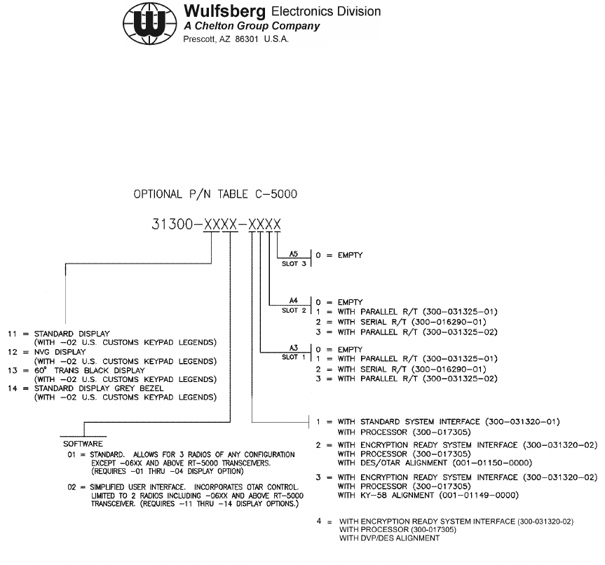
D. Part Numbering
The C-5000's basic unit part number 31300-XXXX-XXXX is configured as follows:
Figure 1-1. C-5000 Part Numbering
Note: Processor board PN 300-031315 can only be used with Parallel R/T board
PN 300-031325. Processor board PN 300-017305 can be used with Parallel
R/T PN 300-031325 and Serial R/T board PN 300-016290.
The installation and operation of the Frequency Agile C-5000 Control Unit is
limited to aircraft installations per FCC Rules and Regulations, Part 90, Section
90.423 and 90.203(h). A non-frequency agile C-5000 is available for other than
aircraft installations and is in compliance with FCC Rules and Regulations
90.203(g).

C-5000 COMMUNICATION MANAGEMENT CONTROLLER
INSTALLATION MANUAL
Publication No. 150-041118 Page 1-5
Rev A Section 1 - Introduction
Sep 2001
Table 1-1. RT-5000 Part Numbers
Part Number RT-5000 Description
400-015525-0101 Transceiver, No Guard Receiver
400-015525-0201 Transceiver, Crystal Controlled Guard Receiver, 30MHz -50MHz
400-015525-0301 Transceiver, Crystal Controlled Guard Receiver, 138 MHz - 174 MHz
400-015525-0401 Transceiver, Crystal Controlled Guard Receiver, 406 MHz - 512 MHz
400-015525-0501 Transceiver, Synthesized Guard
400-015525-0611 Transceiver, D.E.S. Encrypted VHF 138-174 MHz MTM Guard Receiver
400-015525-0711 Transceiver, VHF 138 MHz MTM Guard Receiver
400-015525-0811 Transceiver, D.E.S. Encrypted UHF403 MHz MTM Guard Receiver
400-015525-0911 Transceiver, UHF403 MHz MTM Guard Receiver
400-015525-1011 Transceiver, D.E.S. Encrypted UHF450-520 MHz MTM Guard Receiver
400-015525-1111 Transceiver, UHF520 MHz MTM Guard Receiver
400-015525-1211 Transceiver, D.E.S. Encrypted UHF800 Trunk MHz MTM Guard Receiver
400-015525-1311 Transceiver, UHF800 MHz MTM Guard Receiver
400-015525-1411 Transceiver, D.E.S. Encrypted VHF138 MHz MTM Guard Receiver and
UHF800 MHz MTM Guard Receiver
400-015525-1511 Transceiver, VHF138 MHz MTM Guard Receiver and UHF800 MHz MTM
Guard Receiver
400-015525-1611 Transceiver, D.E.S. Encrypted VHF138 MHz MTM Guard Receiver and D.E.S.
Encrypted UHF800 MHz MTM Guard Receiver
400-015525-1711 Transceiver, VHF138 MHz MTM Guard Receiver and D.E.S. Encrypted
UHF800 MHz MTM Guard Receiver
400-015525-1811 Transceiver, D.E.S. Encrypted VHF138 MHz MTM Guard Receiver and
UHF520 MHz MTM Guard Receiver
400-015525-1911 Transceiver, VHF138 MHz MTM Guard Receiver and UHF520 MHz MTM
Guard Receiver
400-015525-2011 Transceiver, D.E.S. Encrypted VHF138 MHz MTM Guard Receiver and D.E.S.
Encrypted UHF520 MHz MTM Guard Receiver
400-015525-2111 Transceiver, VHF138 MHz MTM Guard Receiver and D.E.S. Encrypted
UHF520 MHz MTM Guard Receiver
400-015525-2211 Transceiver, D.E.S. Encrypted VHF138 MHz MTM Guard Receiver and
UHF403 MHz MTM Guard Receiver
continues…
C-5000 COMMUNICATION MANAGEMENT CONTROLLER
INSTALLATION MANUAL
Page 1-6 Publication No. 150-041118
Section 1 - Introduction Rev A
Sep 2001
Table 1-1. RT-5000 Part Numbers (cont’d)
Part Number RT-5000 Description
400-015525-2311 Transceiver, VHF138 MHz MTM Guard Receiver and UHF403 MHz MTM
Guard Receiver
400-015525-2411 Transceiver, D.E.S. Encrypted VHF138 MHz MTM Guard Receiver and D.E.S.
Encrypted UHF403 MHz MTM Guard Receiver
400-015525-2511 Transceiver, VHF138 MHz MTM Guard Receiver and D.E.S. Encrypted
UHF403 MHz MTM Guard Receiver
400-015525-2611 Transceiver, DVI-XL UHF520 MHz MTM Guard Receiver
400-015525-2711 Transceiver, DVI-XL UHF800 MHz MTM Guard Receiver
Table 1-2. FLEXCOMM II Antenna Part Numbers
Part Number Antenna Description
121-040130-01 AT-560 -- 29.7 - 960 MHz 9.5” Tuned Multiband White
121-040130-02 AT-560 -- 29.7 - 960 MHz 9.5” Tuned Multiband Black
121-040129-01 AT-160 -- 29.7 – 960 MHz 9.5” Passive Multiband
121-040045-01 AT-5000 -- 29.7 – 960 MHz 5.5” (FC-5000 Req) White
121-040045-02 AT-5000 -- 29.7 – 960 MHz 5.5” (FC-5000 Req) Black
121-017850-01 AT-550 -- 29.7 – 960 MHz (FC-550 Req) White
153-017822-01 AT-150 -- 29.7 – 960 MHz (poor 30-88 MHz) White
121-016587-01 AT-50 -- 29.7 - 400MHz Autotuned Blade White
121-016796-01 AT-51 -- 29.7 - 400MHz Autotuned Blade White
121-016584-01 AT-140 -- 29.7MHz - 400MHz Blade White
121-016821-01 AT-400 -- 400MHz - 960MHZ Jet Blade White
153-016586-01 FC-50 Logic Converter -- Antenna Tuner for AT-50/51
153-040047-01 FC-5000 -- Antenna Tuner for AT-5000 and AT-560
153-017851 FC-550 Logic Converter
146-016958-01 Gasket, AT-400
146-014960-01 Gasket, AT-51
146-014959-01 Gasket, AT-50
C-5000 COMMUNICATION MANAGEMENT CONTROLLER
INSTALLATION MANUAL
Publication No. 150-041118 Page 1-7
Rev A Section 1 - Introduction
Sep 2001
Table 1-3. RT-30 Part Numbers
Part Number RT-30 Description
400-0098-000 Transceiver, FLEXCOMM Lo Band VHF, 29.70-49.99 MHz.
400-0098-001 Transceiver, FLEXCOMM Lo Band VHF, 29.70 - 49.99 MHz, with Guard
Receiver
400-0098-002 Transceiver, FLEXCOMM Lo Band VHF, 29.70 - 49.99 MHz, with Guard
Receiver and Guard Receiver CTCSS Tones.
Table 1-4. RT-118 Part Numbers
Part Number RT-118 Description
400-0119-000 Transceiver, FLEXCOMM VHF-AM Band 118.000 - 137.975 MHz,
Standard Receiver IF Bandwidth
400-0119-001 Transceiver, FLEXCOMM VHF-AM Band 118.000 - 137.975 MHz,
Wide Receiver IF Bandwidth
Table 1-5. RT-138 Part Numbers
Part Number RT-138 Description
400-0102-000 Transceiver, FLEXCOMM Hi Band VHF, 138.0000 - 173.9975 MHz
400-0102-001 Transceiver, FLEXCOMM Hi Band VHF, 138.0000 - 173.9975 MHz, with
Guard Receiver.
400-0102-002 Transceiver, FLEXCOMM Hi Band VHF, 138.0000 - 173.9975 MHz, with
Guard Receiver and Guard Receiver CTCSS Tones
400-0102-003 Transceiver, FLEXCOMM Hi Band VHF, 138.0000 - 173.9975 MHz, with
increased sensitivity (precludes Guard).

C-5000 COMMUNICATION MANAGEMENT CONTROLLER
INSTALLATION MANUAL
Page 1-8 Publication No. 150-041118
Section 1 - Introduction Rev A
Sep 2001
Table 1-6. RT-138F Part Numbers
Part Number RT-138F Description
400-014525-00 Transceiver, FLEXCOMM Hi Band VHF, 138.0000-173.9975 MHz.
400-014525-01 Transceiver, FLEXCOMM Hi Band VHF, 138.0000 - 173.9975 MHz, with
Guard Receiver.
400-014525-02 Transceiver, FLEXCOMM Hi Band VHF, 138.0000 - 173.9975MHz, with Guard
Receiver and Guard Receiver CTCSS Tones.
400-014525-03 Transceiver, FLEXCOMM Hi Band VHF, 138.0000 - 173.9975 MHz, with
increased sensitivity (precludes Guard).
400-014525-50 Transceiver, FLEXCOMM Hi Band VHF, 138.0000 - 173.9975 MHz, Voice
Encryption interface compatible.
400-014525-51 Transceiver, FLEXCOMM Hi Band VHF, 138.0000 - 173.9975 MHz, with
Guard Receiver, Voice Encryption interface compatible.
400-014525-52 Transceiver, FLEXCOMM Hi Band VHF, 138.0000 - 173.9975 MHz, with
Guard Receiver, Guard Receiver CTCSS Tones and Voice Encryption
interface compatible.
400-014525-53 Transceiver, FLEXCOMM Hi Band VHF, 138.0000 - 173.9975 MHz, with
increased sensitivity and Voice Encryption interface compatible (precludes
Guard).
Note: All RT-138F units are compatible with Voice Encryption systems utilizing Non Return to
Zero (NRZ) modulation at a data rate of 12 Kbit/sec or less. The -5X units are
specifically wired to readily interface with Motorola and General Electric encryption
modules. Additionally, all RT-138F units are compatible with Digital Coded Squelch
Systems (Motorola Digital Private Line and GE Digital Channel Guard).

C-5000 COMMUNICATION MANAGEMENT CONTROLLER
INSTALLATION MANUAL
Publication No. 150-041118 Page 1-9
Rev A Section 1 - Introduction
Sep 2001
Table 1-7. RT-406F Part Numbers
Part Number RT-406F Description
400-012785-00 Transceiver, FLEXCOMM UHF Band, 406.0000 511.9875 MHz.
400-012785-01 Transceiver, FLEXCOMM UHF Band, 406-0000 511.9875 MHz, with Guard
Receiver.
400-012785-02 Transceiver, FLEXCOMM UHF Band, 406.0000 511.9875 MHz, with Guard
Receiver and Guard Receiver CTCSS Tones.
400-012785-03 Transceiver, FLEXCOMM UHF Band, 406.0000 511.9875 MHz, with increased
sensitivity (precludes Guard).
400-012785-50 Transceiver, FLEXCOMM UHF Band, 406.0000 511.9875 MHz, Voice
Encryption interface compatible
400-012785-51 Transceiver, FLEXCOMM UHF Band, 406.0000 511.9875 MHz, with Guard
Receiver, Voice Encryption interface compatible
400-012785-52 Transceiver, FLEXCOMM UHF Band, 406.0000 511.9875 MHz, with Guard
Receiver, Guard Receiver CTCSS Tones and Voice Encryption interface
compatible
400-012785-53 Transceiver, FLEXCOMM UHF Band, 406.0000 511.9875 MHz, with increased
sensitivity and Voice Encryption interface compatible (precludes Guard).
Note: All RT-406F units are compatible with Voice Encryption systems utilizing Non Return to
Zero (NRZ) modulation at a data rate of 12 Kbit/sec or less. The -5X units are
specifically wired to readily interface with Motorola and General Electric encryption
modules. Additionally, all RT-406F units are compatible with Digital Coded Squelch
Systems (Motorola Digital Private Line and GE Digital Channel Guard).
Table 1-8. RT-450 Part Numbers
Part Number RT-450 Description
400-0103-000 Transceiver, FLEXCOMM UHF Band, 450.0000 - 469.9875 MHz.
400-0103-001 Transceiver, FLEXCOMM UHF Band, 450.0000 - 469.9875 MHz, with Guard
Receiver.
400-0103-002 Transceiver, FLEXCOMM UHF Band, 450.0000 - 469.9875 MHz, with Guard
Receiver and Guard Receiver CTCSS Tones.
400-0103-003 Transceiver, FLEXCOMM UHF Band, 450.0000 - 469.9875 MHz, with
increased sensitivity (precludes Guard).
C-5000 COMMUNICATION MANAGEMENT CONTROLLER
INSTALLATION MANUAL
Page 1-10 Publication No. 150-041118
Section 1 - Introduction Rev A
Sep 2001
Table 1-9. RT-7200 Part Numbers
Part Number RT-7200 Description
400-0087-000 Transceiver, RT-7200 VHF HI-Band, 138.0000 - 173.995 MHz, 14/28 VDC,
100mW Audio, Recessed Connector.
400-0087-001 Transceiver, RT-7200 VHF HI-Band, 138.00 - 173.995 MHz, 14/28 VDC,
100mW Audio, Recessed Connector, with Guard Receiver.
400-0087-002 Transceiver, RT-7200 VHF HI-Band, 138.0000 - 173.995 MHz, 14/28 VDC,
100mW Audio, Recessed Connector, with CTCSS Tones.
400-0087-003 Transceiver, RT-7200 VHF HI-Band, 138.0000 - 173.995 MHz, 14/28 VDC,
100mW Audio, Recessed Connector, with Guard Receiver and CTCSS Tones.
Table 1-10. RT-9600 Part Numbers
Part Number RT-9600 Description
400-0052-002 Transceiver, RT-9600 VHF HI-Band, 150.0000 - 173.995 MHz, 14/28 VDC,
100 mW Audio, Protruding Connector
400-0052-005 Transceiver, RT-9600 VHF HI-Band, 150.0000 - 173.995 MHz, 14/28 VDC,
100 mW Audio, Protruding Connector, with Guard Receiver
400-0052-008 Transceiver, RT-9600 VHF HI-Band, 150.0000 - 173.995 MHz, 4/28 VDC,
100 mW Audio, Protruding Connector with CTCSS Tones
400-0052-011 Transceiver, RT-9600 VHF HI-Band, 150.0000 - 173.995 MHz, 14/28 VDC,
100 mW Audio, Protruding Connector, with Guard Receiver and CTCSS Tones
400-0052-024 Transceiver, RT-9600 VHF HI-Band, 150.0000 - 173.995 MHz, 14/28VDC,
100 mW Audio, Recessed Connector
400-0052-025 Transceiver, RT-9600 VHF HI-Band, 150.0000 - 173.995 MHz, 14/28 VDC,
100 mW Audio, Recessed Connector, with Guard Receiver
400-0052-026 Transceiver, RT-9600 VHF HI-Band, 150.0000 - 173.995 MHz, 14/28 VDC,
100 mW Audio, Recessed Connector, with CTCSS Tones
400-0052-027 Transceiver, RT-9600 VHF HI-Band, 150.0000 - 173.995 MHz, 14/28 VDC,
100 mW Audio, Recessed Connector, with Guard Receiver and CTCSS Tones

C-5000 COMMUNICATION MANAGEMENT CONTROLLER
INSTALLATION MANUAL
Publication No. 150-041118 Page 1-11
Rev A Section 1 - Introduction
Sep 2001
Table 1-11. RT-9600F Part Numbers
Part Number RT-9600F Description
400-0140-002 Transceiver, RT-9600F VHF HI-Band, 150.0000 - 173.995 MHz, 14/28 VDC,
100 mW Audio, Protruding Connector
400-0140-005 Transceiver, RT-9600F VHF HI-Band, 150.0000 - 173.995 MHz, 14/28 VDC,
100 mW Audio, Protruding Connector, with Guard Receiver
400-0140-008 Transceiver, RT-9600F VHF HI-Band, 150.0000 - 173.995 MHz, 14/28 VDC,
100 mW Audio, Protruding Connector with CTCSS Tones
400-0140-011 Transceiver, RT-9600F VHF HI-Band, 14/28 VDC, 100 mW Audio, Protruding
Connector, with Guard Receiver and CTCSS Tones
400-0140-024 Transceiver, RT-9600F VHF HI-Band, 150.0000 - 173.995 MHz, 14/28VDC,
100 mW Audio, Recessed Connector
400-0140-025 Transceiver, RT-9600F VHF HI-Band, 150.0000 - 173.995 MHz, 14/28 VDC,
100 mW Audio, Recessed Connector, with Guard Receiver
400-0140-026 Transceiver, RT-9600F VHF HI-Band, 150.0000 - 173.995 MHz, 14/28 VDC,
100 mW Audio, Recessed Connector, with CTCSS Tones
400-0140-027 Transceiver, RT-9600F VHF HI-Band, 150.0000 - 173.995 MHz, 14/28 VDC,
100 mW Audio, Recessed Connector, with Guard Receiver and CTCSS Tones
040-0140-052,
400-0140-152 Transceiver, RT-9600F VHF HI-Band, 150.0000 -173.995 MHz, 14/28 VDC,
100 mW Audio, Protruding Connector and Voice Encryption interface
compatible
400-0140-055,
400-0140-155 Transceiver, RT-9600F VHF HI-Band, 150.0000 - 173.995 MHz, 14/28 VDC,
100 mW Audio, Protruding Connector, and Voice Encryption interface
compatible
400-0140-058,
400-0140-158 Transceiver, RT-9600F VHF HI-Band, 150.0000 - 173.995 MHz, 14/28 VDC,
100 mW Audio, Protruding Connector with CTCSS Tones, and Voice
Encryption interface compatible
400-0140-061,
400-0140-1611 Transceiver, RT-9600F VHF HI-Band, 150.0000 - 173.995 MHz, 14/28 VDC,
100 mW Audio, Protruding Connector, with Guard Receiver and CTCSS
Tones, and Voice Encryption interface compatible
400-0140-074,
400-0140-174 Transceiver, RT-9600F VHF HI-Band, 150.0000 - 173.995 MHz, 14/28 VDC,
100 mW Audio, Recessed Connector, and Voice Encryption interface
compatible
400-0140-075,
400-0140-175 Transceiver, RT-9600F VHF HI-Band, 150.0000 - 173.995 MHz, 14/28 VDC,
100 mW Audio, Recessed Connector, with Guard Receiver, and Voice
Encryption interface compatible
continues…

C-5000 COMMUNICATION MANAGEMENT CONTROLLER
INSTALLATION MANUAL
Page 1-12 Publication No. 150-041118
Section 1 - Introduction Rev A
Sep 2001
Table 1-11. RT-9600F Part Numbers (Cont’d)
Part Number RT-9600F Description
400-0140-076,
400-0140-176 Transceiver, RT-9600F VHF HI-Band, 150.0000 - 173.995 MHz, 14/28 VDC,
100 mW Audio, Recessed Connector, with CTCSS Tones, and Voice
Encryption interface compatible
400-0140-077,
400-0140-177 Transceiver, RT-9600F VHF HI-Band, 150.0000 - 173.995 MHz, 14/28 VDC,
100 mW Audio, Recessed Connector, with Guard Receiver and CTCSS
Tones, and Voice Encryption interface compatible
Note: All RT-9600F units are compatible with Voice Encryption systems utilizing Non Return to
Zero (NRZ) modulation at a data rate of 12 Kbit/sec or less. The -05X, -06X, and -07X
units are specifically wired to readily interface with Motorola encryption modules.
Additionally, all RT-9600F units are compatible with Digital Coded Squelch Systems
(Motorola Digital Private Line and GE Digital Channel Guard).
C-5000 COMMUNICATION MANAGEMENT CONTROLLER
INSTALLATION MANUAL
Publication No. 150-041118 Page 2-1
Rev A Section 2 – System Installation
Sep 2001
SECTION 2 - SYSTEM INSTALLATION
1. General
This section contains system specifications, interface information, and examples of typical system
configurations for the C-5000 Communication Management Controller installed with FLEXCOMM
II, FLEXCOMM I, or a configuration consisting of both FLEXCOMM II and FLEXCOMM I
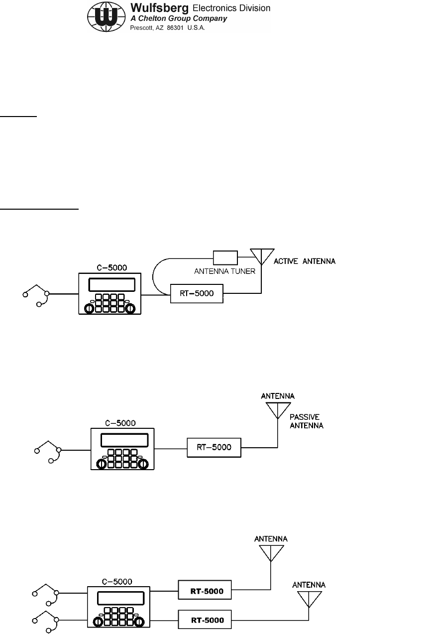
transceivers. System power requirements are included in Table 2-1. Figures 2-1 through 2- 6
show generalized system interface diagrams.
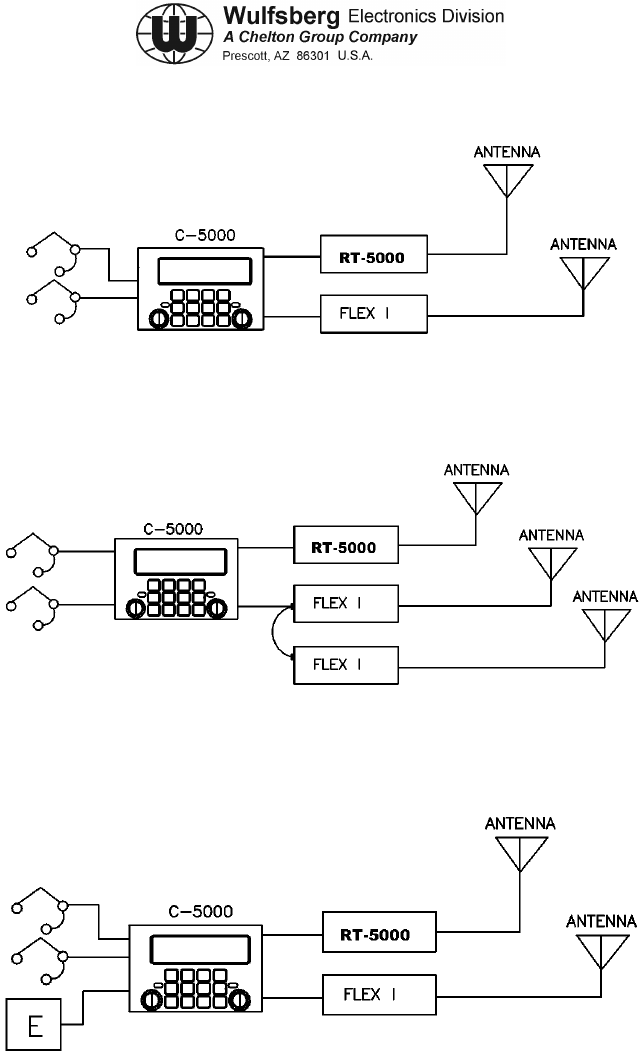
2. Sample Systems
The following are examples of ways to configure your aircraft installation:
Figure 2-1. Single RT-5000 with Active Antenna
Figure 2-2. Single RT-5000 with Passive Antenna
Figure 2-3. Dual RT-5000 with Dual Mic/Headset
ACTIVE OR PASSIVE
ANTENNA
ACTIVE OR PASSIVE
ANTENNA
C-5000 COMMUNICATION MANAGEMENT CONTROLLER
INSTALLATION MANUAL
Page 2-2 Publication No. 150-041118
Section 2 – System Installation Rev A
Sep 2001
Figure 2-4. Dual Transceiver, RT-5000 and Flexcomm I
Figure 2-5. Dual Transceiver, RT-5000 and Parallel Flexcomm I Transceivers
Figure 2-6. Dual Transceiver with External Encryption
C-5000 COMMUNICATION MANAGEMENT CONTROLLER
INSTALLATION MANUAL
Publication No. 150-041118 Page 2-3
Rev A Section 2 – System Installation
Sep 2001
3. Component Specifications
COMPONENT POWER REQUIREMENTS
C-5000 VOLTAGE: 27.5 Vdc ± 20% Aircraft
CURRENT: 0.4 amps (typical)
1.3 amps (maximum external loading)
FLEXCOMM II
RT-5000 VOLTAGE: 27.5 VDC Aircraft
STANDBY: 1.7 amps
RECEIVE: 1.7 amps
TRANSMIT: 10.0 amps
FLEXCOMM I RT-30
RT-118
RT-138
RT-138F
RT-406F
RT-450
RT-9600
RT-9600F
RT-7200
Refer to FLEXCOMM I Transceiver System Installation
Manual, Manual Number 150-040011, for power
requirements.
Refer to VHF/FM Transceivers RT-7200, RT-9600,
AN/ARC-513(V) Installation /Operators Manual, Manual
Number 150-0061-000, for power requirements.
Table 2-1. System Power Requirements
A. C-5000 Communication Management Controller
Note: The installation and operation of the Frequency Agile C-5000 Control Unit is limited
to aircraft installations per FCC Rules and Regulations, Part 90, Section 90.423 and
90.203(h). A non-frequency agile C-5000 is available for other than aircraft
installations and is in compliance with FCC Rules and Regulations 90.203(g).
(1) Number of Channels: 350 programmable channels
(2) Temperature: -30° to + 60° C
(3) Panel Lighting: 5 Vdc, 5 Vac, or 28 Vdc
(4) Keypad Lighting: Type: Electro Luminescent (E.L.) Lighting
Color: Blue/white (standard)
Green NVG (optional

C-5000 COMMUNICATION MANAGEMENT CONTROLLER
INSTALLATION MANUAL
Page 2-4 Publication No. 150-041118
Section 2 – System Installation Rev A
Sep 2001
(5) Audio Output: Standard: 100 mV into 600 ohm load, shop adjustable
0.1 to 250 mW, 600 ohms
Unsquelched Audio: 0.5 VRMS/2k ohms, adjustable 0.1
to 1.5 V
(6) Audio Input Level: Std. Voice: 0.25 Vrms 150 ohm balanced pair, shop
adjustable 30 mV to 1.5 Vrms Narrowband: same as
voice, 2K single ended
(7) Microphone Interface: Carbon or equivalent
B. FLEXCOMM II (RT-5000)
(1) RT-5000 Transceiver
a) Tunability: 1.25 kHz Incremental Tuning Simplex/Semi-duplex.
b) Mode: FM/AM/P25/Trunking
c) Frequency Bands: 29.7-88 MHz (FM Band)
108-116 MHz (receive only)
118-156 MHz (AM Band)
138-174 MHz (FM Band)
220-225 MHz (AM/FM)
225-400 MHz (AM/FM)
FM:
403-512 MHz
512-806 MHz
806-960 MHz
d) Channeling: 12.5/20/25/30/50 kHz
e) Temperature: -30° C to + 60° C
f) Altitude: 51,000 feet above MSL
g) Control: C-5000 Serial Tuning Bus
h) Tx Power: 10 Watts FM/P25
15 Watts AM

C-5000 COMMUNICATION MANAGEMENT CONTROLLER
INSTALLATION MANUAL
Publication No. 150-041118 Page 2-5
Rev A Section 2 – System Installation
Sep 2001
C. RT-5000 Antennas
1) AT-560 Antenna
1) Frequency: 29.7 - 960 MHz
2) VSWR: 2.5:1 maximum
3) Radiation Pattern: Omnidirectional in azimuth
4) Polarization: Vertical
5) Impedance: 50 ohms
6) Power: 20 Watts
7) Gain: 30 MHz, -14 dBi
88 MHz, -6 dBi
108-174 MHz, 0 dBi
220-960 MHz, 0 dBi
8) Temperature: -55°C to + 70°C
9) Altitude: 40,000 feet
2) AT-160 Antenna
1) Frequency: 29.7 - 960 MHz
2) VSWR: 2.5:1 maximum
3) Radiation Pattern: Omnidirectional in azimuth
4) Polarization: Vertical
5) Impedance: 50 ohms
6) Power: 20 Watts
7) Gain: 30 MHz, -21 dBi
60 MHz, -21 dBi
88 MHz, -12 dBi
108-174 MHz, -3 dBi
225-960 MHz, 0 dBi
8) Temperature: -55°C to + 70°C
9) Altitude: 40,000 feet
3) AT-5000 Antenna

C-5000 COMMUNICATION MANAGEMENT CONTROLLER
INSTALLATION MANUAL
Page 2-6 Publication No. 150-041118
Section 2 – System Installation Rev A
Sep 2001
1) Frequency: 29.7 - 960 MHz
2) VSWR: 2.5:1 maximum
3) Radiation Pattern: Omnidirectional in azimuth
4) Polarization: Vertical
5) Impedance: 50 ohms
6) Power: 20 Watts
7) Gain: 30 MHz, -15 dBi
88 MHz, -7.5 dBi
118-174 MHz, -3 dBi
225-960 MHz, 0 dBi
8) Temperature: -55°C to + 70°C
9) Altitude: 55,000 feet
4) AT-550 Antenna
1) Frequency: 29.7 - 960 MHz
2) VSWR: 2.5:1 maximum
3) Radiation Pattern: Omnidirectional in azimuth
4) Polarization: Vertical
5) Impedance: 50 ohms
6) Power: 20 Watts
7) Gain: 30 MHz, -14 dBi
88 MHz, -6 dBi
108-174 MHz, 0 dBi
225-960 MHz, 0 dBi
8) Temperature: -55°C to + 70°C
9) Altitude: 40,000 feet

C-5000 COMMUNICATION MANAGEMENT CONTROLLER
INSTALLATION MANUAL
Publication No. 150-041118 Page 2-7
Rev A Section 2 – System Installation
Sep 2001
5) AT-50 Antenna
1) Frequency: 29.7 - 400 MHz
2) VSWR: 2: 1 maximum
3) Radiation Pattern: Omnidirectional in azimuth
4) Polarization: Vertical
5) Impedance: 50 ohms
6) Power: 20 Watts
7) Gain: 30 MHz, -11 dBi
88 MHz, -6 dBi
108-174 MHz, 0 dBi
225-400 MHz, + 2 dBi
8) Temperature: -54°C to + 71°C
9) Altitude: 50,000 feet
6) AT-51 Antenna
1) Frequency: 29.7 - 400 MHz
2) VSWR: 2.5: 1 maximum
3) Radiation Pattern: Omnidirectional in azimuth
4) Polarization: Vertical
5) Impedance: 50 Ohms
6) Power: 15 Watts
7) Gain: 30 MHz, -14 dBi
88 MHz, -7 dBi
108-174 MHz, -3 dBi
225-400 MHz, 0 dB
8) Temperature: -54°C to + 71°C
9) Altitude: 50,000 feet

C-5000 COMMUNICATION MANAGEMENT CONTROLLER
INSTALLATION MANUAL
Page 2-8 Publication No. 150-041118
Section 2 – System Installation Rev A
Sep 2001
7) AT-140 Antenna
1) Frequency: 29.7 - 400 MHz
2) VSWR: 2.5: 1 at 30-88 MHz
5.0: 1 at 108-117 MHz
2.5: 1 at 118-174 MHz
2.0: 1 at 225-400 MHz
3) Radiation Pattern: Omnidirectional in azimuth
4) Polarization: Vertical
5) Impedance: 50 ohms
6) Power: 50 Watts
7) Gain: 30 MHz -22.5 dBi
88 MHz -10 dBi
108 - 174 MHz -2 dBi
225 - 400 MHz +2 dBi
8) Temperature: -54°C to + 71°C operating
-62°C to + 85°C non-operating
9) Altitude: 50,000 ft
8) AT-400 Antenna.
1) Frequency: 400 - 960 MHz
2) VSWR: 2.0: 1 maximum
3) Radiation Pattern: Typical of λ/4 stub
4) Polarization: Vertical
5) Impedance: 50 ohms
6) RF Power: 100 Watts
7) Efficiency: 90% min. 400 - 960 MHz
8) Temperature: -55°C to +70°C
9) Altitude: 50,000 ft

C-5000 COMMUNICATION MANAGEMENT CONTROLLER
INSTALLATION MANUAL
Publication No. 150-041118 Page 2-9
Rev A Section 2 – System Installation
Sep 2001
D. FLEXCOMM I
Note: Refer to FLEXCOMM I Transceiver System Installation Manual, Manual Number
150-040011, for specification data on FLEXCOMM Transceivers and Antennas.
Refer to VHF/FM Transceivers RT-7200, RT-9600, AN/ARC-513(V) Installation
/Operators Manual, Manual Number 150-0061-000, for specification data on
RT-9600 and RT-7200 transceivers.

C-5000 COMMUNICATION MANAGEMENT CONTROLLER
INSTALLATION MANUAL
Page 2-10 Publication No. 150-041118
Section 2 – System Installation Rev A
Sep 2001
This page intentionally left blank.

C-5000 COMMUNICATION MANAGEMENT CONTROLLER
INSTALLATION MANUAL
Publication No. 150-041118 Page 3-1
Rev A Section 3 – Mechanical Installation
Sep 2001
SECTION 3 - MECHANICAL INSTALLATION
1. General
This section contains instructions and considerations for the proper mechanical installation of the
C-5000 Communication Management Controller with FLEXCOMM II and FLEXCOMM I Systems.
The information presented here is necessary for the proper operation and satisfactory
performance of the equipment.
The FLEXCOMM II System consists of the RT-5000 Transceiver, appropriate antennas, and
optional equipment as required.
The FLEXCOMM I System consists of an RT-9600F, or an RT-9600, or an RT-7200, or a
combination of up to 3 of the following transceivers: RT-30, RT-118, RT-138, RT-138F, RT-406F,
RT-450, appropriate antenna(s), and optional equipment as required.
Note: An RT-138 transceiver or an RT-138F transceiver (not both) may be installed in the
same RT-System. An RT-406F transceiver or an RT-450 transceiver (not both) may be
installed in the same RT System.
Refer to FLEXCOMM I Transceiver System Installation Manual, Manual Number 150-
040011, for mechanical installation information on FLEXCOMM transceivers. Refer to
VHF/FM Transceivers RT-7200, RT-9600, AN/ARC-513(V) Installation /Operators
Manual, Manual Number 150-0061-000, for mechanical installation information on the
RT-9600, and RT-7200 transceivers.
For instructions and considerations on the mechanical installation of a configuration that consists
of both FLEXCOMM II and FLEXCOMM I transceivers, refer to applicable information in this
section for the installation of FLEXCOMM II transceivers, and to the documents noted in the
previous paragraph for installation of FLEXCOMM I transceivers.
2. Unpacking and Inspecting Equipment
Physically compare the presence of each item in the shipment with that shown on the packing list.
Exercise care when unpacking each unit. Make a visual inspection of each unit for evidence of
damage incurred during shipment. If a claim for damage is to be made, save the shipping
container to substantiate the claim. When all equipment is unpacked, it is suggested the carton
and packing materials be saved for possible reshipment.
C-5000 COMMUNICATION MANAGEMENT CONTROLLER
INSTALLATION MANUAL
Page 3-2 Publication No. 150-041118
Section 3 – Mechanical Installation Rev A
Sep 2001
3. General Installation Requirements
A. Component Weights
Component Weight
C-5000 3.1 to 3.9 lbs (1.4 to1.8 kg) depending on configuration
RT-5000 16.2 to 19.7 lbs (7.3 to 8.9 kg) depending on configuration
AT-560 2.7 lbs (1.2 kg)
AT-160 2.7 lbs (1.2 kg)
AT-5000 3.5 lbs (1.6 kg)
AT-550 2.7 lbs (1.2 kg)
AT-150 2.7 lbs (1.2 kg)
AT-50 4.8 lbs max (2.18 kg)
AT-51 3.1 lbs max (1.41 kg)
AT-140 4.0 lbs max (1.8 kg)
AT-400 .75 lbs max (.34 kg)
FC-50 1.65 lbs max (0.75 kg)
FC-5000 1.65 lbs (0.75 kg)
FC-550 1.75 lbs (0.79 kg)
HA-4 1.13 lbs (0.51 kg)
FLEXCOMM I
Components Refer to appropriate Installation Manual
Table 3-1. Component Weights
C-5000 COMMUNICATION MANAGEMENT CONTROLLER
INSTALLATION MANUAL
Publication No. 150-041118 Page 3-3
Rev A Section 3 – Mechanical Installation
Sep 2001
4. Installation of Multipin Crimp Connectors
A. Contacts and Crimp Tool Information
Contacts, D-Sub, Min.
Crimp or Solder WED PN 129-115451-01
Positronic PN FC8122D, crimp (or equivalent) or
Positronic FS8122D, solder (or equivalent)
Crimp Tools
(Suggested supplier:
Daniels Manufacturing
Corporation
526 Thorpe Road
Orlando, FL 32824)
C-5000 Serial RT Card interface Connector
Handle - M22520/2-01
Positioner - M22520/2-08
C-5000 Parallel RT Card Interface Connector
Handle - M22520/2-01
Positioner - M22520/2-06
RT-5000 Interface Connector
Tool Frame - M22520/1-01
Turret - M22520/1-02
Positioner - M22520/2-08
Insertion/Removal Tool Positronic M81969/1-04 or equivalent
B. Contacts and Insertion/Removal Tool Manufacturer Name and Address:
Positronic Industries, Inc.
423 N. Campbell Ave.
PO Box 8247
Springfield, Missouri 65801
5. Installation of C-5000
Mount C-5000 on Dzus/rails per MIL MS-25213.
See Figure 3-1 for mounting dimensions.
6. Installation of RT-5000
The RT-5000 is designed for horizontal or vertical fixed tray mounting. However, vertical
mounting results in better cooling. A minimum of 1 inch clearance is required on all
sides.
1. Firmly hand-tighten the rack knobs to secure the RT-5000 in the mounting tray. See
Figures 3-2 through 3-4 for mounting dimensions.
2. Attach antenna cabling [Connector J103 (N Type, less-than-or equal-to 400 MHz), and
J102 (TNC Type, greater-than-or-equal-to 400 MHz)]. Insure proper connector mating.
3. Attach RT-5000 mating Connector J101 (55 pin).

C-5000 COMMUNICATION MANAGEMENT CONTROLLER
INSTALLATION MANUAL
Page 3-4 Publication No. 150-041118
Section 3 – Mechanical Installation Rev A
Sep 2001
7. Installation of Antennas
The antenna should be mounted on the bottom of the aircraft if possible.
Unpainted aluminum base must make good electrical contact with airframe. Antenna should be
installed on flat surface.
A bead of sealant such as Dow Corning RTV-738 should be applied to the outside perimeter of
the mounting surface.
See Figures 3-5 through 3-15 for appropriate antenna mounting dimensions.
A. AT-560 and AT-5000
See the AT-560 and AT-5000 envelope drawings, Figures 3-5 and 3-7, for dimensions.
Mount antenna with No. 10 screws.
B. FC-5000
Note: The FC-5000 Logic Converter is required for the AT-560 and AT-5000 antennas.
See the FC-5000 envelope drawing, Figure 3-15, for dimensions.
C. AT-160 and AT-150
See the AT-160 and AT-150 envelope drawings, Figures 3-6 and 3-9, for dimensions.
Mount antenna with No. 10 screws.
D. AT-550
See the AT-550 envelope drawing, Figure 3-8, for dimensions.
Mount antenna with No. 10 screws.
D. FC-550
Note: The FC-550 Logic Converter is required for the AT-550 antenna.
See the FC-550 envelope drawing, Figure 3-16, for dimensions.
F. AT-50 and AT-51
If antenna is installed on top of aircraft, drainage holes at smaller end of antenna should be
plugged with blanking plugs and RTV. Drainage holes in antenna base flange at mounting
face should not be obstructed.
If antenna is installed on underside of aircraft, drainage holes at smaller end of antenna base
flange at mounting face should be sealed with a small fillet of RTV.

C-5000 COMMUNICATION MANAGEMENT CONTROLLER
INSTALLATION MANUAL
Publication No. 150-041118 Page 3-5
Rev A Section 3 – Mechanical Installation
Sep 2001
Note: For full 29.7-900 MHz frequency coverage, the user must also install the AT-400
antenna for 400-960 frequencies.
See the AT-50 and AT-51 envelope drawings, Figures 3-10 and 3-11, for dimensions.
Mount antenna with No. 10 screws.
G. FC-50
Note: The FC-50 Logic Converter is required for the AT-50 and AT-51 antennas.
See the FC-50 envelope drawing, Figure 3-14, for dimensions.
H. AT-400
See the AT-400 envelope drawing, Figure 3-13, for dimensions.
Mount antenna with No. 8 screws.
I. AT-140
Note: For full 29.7-400 MHz frequency coverage, the user must also install the AT-140
antenna for 400-960 frequencies.
See the AT-140 envelope drawing, Figure 3-12, for dimensions.
Mount antenna with No. 10 screws.

C-5000 COMMUNICATION MANAGEMENT CONTROLLER
INSTALLATION MANUAL
Page 3-6 Publication No. 150-041118
Section 3 – Mechanical Installation Rev A
Sep 2001
This page intentionally left blank
.

C-5000 COMMUNICATION MANAGEMENT CONTROLLER
INSTALLATION MANUAL
Publication No. 150-041118 Page 3-7
Rev A Section 3 – Mechanical Installation
Sep 2001
Remove this page and insert:
154-031300, Sheet 1 of 1 (Figure 3-1)
154-015525, Sheet 1 of 1 (Figure 3-2)
300-316835, Sheet 1 of 1 (Figure 3-3)
300-316605, Sheet 1 of 1 (Figure 3-4)
121-040130, Sheet 1 of 1 (Figure 3-5)
121-040129, Sheet 1 of 1 (Figure 3-6)
121-040045, Sheet 1 of 1 (Figure 3-7)
121-017850, Sheet 1 of 1 (Figure 3-8)
153-017822, Sheet 1 of 1 (Figure 3-9)
121-016687, Sheet 1 of 1 (Figure 3-10)
121-016796, Sheet 1 of 1 (Figure 3-11)
121-016584, Sheet 1 of 1 (Figure 3-12)
121-016821, Sheet 1 of 1 (Figure 3-13)
153-016586, Sheet 1 of 1 (Figure 3-14)
153-040047, Sheet 1 of 1 (Figure 3-15)
153-017851, Sheet 1 of 1 (Figure 3-16)

C-5000 COMMUNICATION MANAGEMENT CONTROLLER
INSTALLATION MANUAL
Page 3-8 Publication No. 150-041118
Section 3 – Mechanical Installation Rev A
Sep 2001
Remove this page.
C-5000 COMMUNICATION MANAGEMENT CONTROLLER
INSTALLATION MANUAL
Publication No. 150-041118 Page 4-1
Rev A Section 4 –Electrical Installation
Sep 2001
SECTION 4 - ELECTRICAL INSTALLATION
1. General
The following section describes the wiring requirements and options for the installation of the
system. Because the system has so many features and options, it is recommended that the
installer take the time to read pin descriptions and all notes on wiring diagrams before designing
an installation.
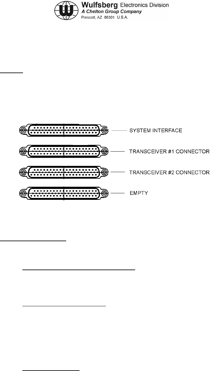
Figure 4-1 Rear View of C-5000
2. Wiring Considerations
To simplify the systems design, follow the steps below:
Step 1: Determine the type and number of radios. The C-5000 can control one or two
transceiver systems. The word system is used because a Flexcomm I installation can be
made of multiple transceivers electrically daisy chained to make one system. Based on the
type of radio, chose the part number of C-5000 that applies to your application.
Step 2: Determine the type of antenna. For each transceiver, determine the appropriate
antenna. For Flexcomm I transceivers, see the proper installation manuals for options. For
the RT-5000, the process begins by determining if the user needs optimum 30-88MHz
performance. If so, the recommended antenna system will be an “active” antenna (i.e. one
that is electrically tuned for maximum performance). If the user rarely uses 30-88 MHz, then
passive antenna is suggested. Passive antennas are less expensive and less complex to
install. Remember that performance in the 30-88 MHz frequency range is very degraded vs.
an active antenna.
Step 3: Microphone/Headset. If only one radio is installed, use the primary mic/headset
port. If two radios are installed, use primary mic/headset for transceiver system #1 and
secondary mic/headset for transceiver system #2. If only one mic/headset port is available
on the audio panel, use the primary mic/headset port and configure the C-5000 to operate in
“single mic mode”.
C-5000 COMMUNICATION MANAGEMENT CONTROLLER
INSTALLATION MANUAL
Page 4-2 Publication No. 150-041118
Section 4 – Electrical Installation Rev A
Sep 2001
Step 4: Panel Lighting. Select the input pin on P500 for the desired backlighting.
Options are 28 Vdc (pin 30) or 5 Vdc/5vrms (pin 8).
Step 5: System Wiring. Based on steps 1-5, choose the wiring diagrams from this
section that apply to your configuration. Note that if you have two RT-5000’s in your system,
copy the wiring illustrated for P501 to P502. In other words, choose the wiring for each radio
and apply it to the appropriate connector.
A. C-5000 System Interface Connector, P500 Wiring Considerations
(1) P500 Connector
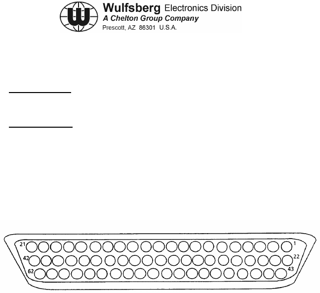
Figure 4-2 P500 Connector

C-5000 COMMUNICATION MANAGEMENT CONTROLLER
INSTALLATION MANUAL
Publication No. 150-041118 Page 4-3
Rev A Section 4 –Electrical Installation
Sep 2001
(2) System Interface Connector P500 Pin Names.
PIN SIGNAL NAME PIN SIGNAL NAME
1 RT-X REXMT AUDIO OUT 32 RESERVED SPARE C
2 RS-422 TX LO 33 RT-X SELECT B
3 XMT AUDIO IN HI 34 RT-X REXMT CONTROL KEY OUT
4 XMT AUDIO COMMON 35 PLAIN/CIPHER SEL
5 INTERNAL CIPHER SEL A 36 EXT. CIPHER ACTIVE
6 INTERNAL CIPHER SEL B 37 RT-X WB MN RCV AUDIO OUT
7 REXMT AUDIO IN 38 RCV'NG EXT ENCRYP TEXT
8 5V LITES 39 HEADSET AUDIO COMMON
9 PRIMARY CARBON MIC Hl 40 PRIMARY HEADSET AUDIO HI
10 SECONDARY CARBON MIC LO 41 SECONDARY MIC PTT
11 SHIELD 42 EXT RT-X DECODED RCV AUDIO
12 CIPHER/PLAIN SEL 43 A/C POWER GND
13 RT-X GUARD AUDIO 0UT 44 27.5 VDC A/C POWER
14 INTERNAL CIPHER DISABLE 45 RS-422 TX HI
15 PTT FROM EXT CIPHER 46 RS-422 RX1 HI
16 RT-X SELECT A 47 RS-422 RX1 LO
17 SECONDARY CARBON MIC HI 48 MIC OUT LO
18 PRIMARY MIC PTT 49 MIC OUT HI
19 XMT'NG EXT ENCRYP TEXT 50 28V LITES
20 SECONDARY HEADSET AUDIO HI 51 RESERVED SPARE E
21 RESERVED SPARE C 52 RESERVED SPARE G
22 SYSTEM (GRD) PRECEDENCE CHN IN 53 RESERVED SPARE A
23 BW CONTROL IN 54 RESERVED SPARE F
24 RS-422 RX2 HI 55 INTERNAL CIPHER SEL C
25 RS-422 RX2 LO 56 PTT TO CIPHER
26 ZEROIZE 57 SPARE B
27 AUX AUDIO IN HI 58 AUX -15VDC
28 AUX +5 VDC 59 SPARE A
29 PRIMARY CARBON MIC LO 60 AUX +15 VDC
30 LITES COMMON 61 EXT RT-X WB XMT AUDIO
31 RESERVED SPARE B 62 AUX GND
Table 4-1. System Interface Connector P500 Pin Names

C-5000 COMMUNICATION MANAGEMENT CONTROLLER
INSTALLATION MANUAL
Page 4-4 Publication No. 150-041118
Section 4 – Electrical Installation Rev A
Sep 2001
(3) Primary Carbon Mic HI/LO (Pins 9, 29)
These pins provide a 150 Ohm input impedance for the crew microphone input. Standard
Carbon Mic bias of 15V through 300 Ohms is provided. Standard modulation of 1 kHz
tone at 0.25 Vrms is factory set for ± 3 kHz deviation although an adjust range of 30 mV
to 1.5 Vrms is provided by A2R174 on the system interface board.
(4) Primary Mic PTT (Pin 18)
This pin, when grounded, activates the transceiver system(s) selected for the primary
mic/headset interface.
Note: The primary mic LO and PTT should be connected together at the mic interface
(audio panel or mic jack). Alternately, the mic LO should be grounded at the mic
interface as mic bias is not provided unless mic LO is DC grounded.
(5) Primary Headset Audio HI/COMMON (Pins 39, 40)
The pins provide receive and sidetone audio output for the transceiver system(s) selected
for the primary mic/headset interface. Standard audio levels of 100 mW into 600 Ohm
load is provided for standard modulation although an adjustment range of 0.5 to 200 mW
is provided by A2R86 of the system interface board.
(6) Secondary Carbon Mic HI/LO, Secondary PTT, and Secondary Headset Audio (Pins
10, 17, 20, 41)
These pins provide a similar interface as the primary counterparts with some functional
exceptions. Although levels and impedances provided are the same, the secondary
interface provides the limited function of talk and listen in clear, non-encrypted audio.
Features provided by the primary interface i.e. Selectable audio routing through internal
or external encryption systems integrated with the C-5000 are not supported at the
secondary interface.
(7) Shield (Pin 11)
All shields of signals originating at the C-5000 and terminating at other equipment should
be connected to this pin and left unterminated at the other equipment. Similarly, the
shields of signals originating at other equipment and terminating at the C-5000 should be
grounded at the other equipment and left unterminated at the C-5000.
(8) 27.5 Vdc A/C Power and Ground (Pin 43, 44)
These pins provide aircraft 27.5 Vdc power to the C-5000 system. Typical loading is
approximately 350 mA, however with external loading by auxiliary equipment connected
to ±15 V and +5 V pins provided, the current requirement can be 1.3 Amp at 27.5 Vdc
and approach 2 Amps at low voltage. Appropriate circuit breaker should be provided with
consideration given to separately powered radio equipment as part of the basic
communications equipment being controlled by the C-5000.

C-5000 COMMUNICATION MANAGEMENT CONTROLLER
INSTALLATION MANUAL
Publication No. 150-041118 Page 4-5
Rev A Section 4 –Electrical Installation
Sep 2001
(9) 28V, 5V, Common Lites (Pins 8, 30, 50)
These pins provide for aircraft lite dimmer bus control of the keyboard lighting. Either
28 Vdc, 5 Vrms or 5 Vdc lighting may be used. The C-5000 does not draw power from
the buss but simply monitors the voltage for proper lite tracking. Only 5 V or 28 V may be
connected at once.
(10) RS-422 TX, RS-422 RX1, RS-422 RX2 HI/LO (Pins 2, 24, 25, 45, 46, 47)
These pins provide for a bi-directional digital data buss to other equipment on board the
aircraft. Two separate receive inputs are provided and the transmit pair may be
connected to multiple RS-422 devices. The receive shields should be connected only at
the originating equipment and the transmit shield should only be connected to the C-5000
shield pin.
(11) Internal Cipher Select A, B, C (Pins 5, 6, 55)
These pins are normally left unterminated and Internal Cipher Selection is managed from
the C-5000. Alternately, pins A, B, and C may be grounded in a binary fashion to provide
external selection of 1 of 7 internal cipher modes.
(12) Internal Cipher Disable (Pin 14)
This pin, when left unterminated, causes audio routing within the C-5000 to include the
Internal Cipher Interface. By grounding this pin, audio routing of the following signals is
to/from the external system interface for utilization with External Encryption Equipment,
auxiliary systems and functions generally used in conjunction with military equipment.
Associated signals routed to the External Interface are:
Mic output, voice band transmit audio input, wideband transmit audio input, wideband
receive audio output, voice band receiver audio output, decoded/de-encrypted voice
band received audio input, guard receiver voice band audio output.
This pin should normally be grounded unless an Internal Cipher module (or other special
module) is installed in the C-5000 and then it should be switched for Internal or External
routing of the "RT-X" signals.
(13) External Cipher Active (Pin 36)
This pin, when grounded, indicates to the C-5000 computer that external encryption
equipment connected to the system interface card is active and activated by external
control.
(14) XMT Audio IN HI/COMMON (Pins 3, 4)
This pair provides a voice band input to the transmitter(s) as selected by the crew.
Typical use is with external encryption equipment in which the mic input to the C-5000 is
routed out to the encryption unit and when the encryption unit is not active, the mic input
(voice band) is returned to this port for normal voice transmit. Standard levels are 0.9
Vrms into 600 Ω, although A2R160 and A2JP3 provide adjustment range of
approximately 40 mV (150 Ω) to 5.4 V (600Ω).

C-5000 COMMUNICATION MANAGEMENT CONTROLLER
INSTALLATION MANUAL
Page 4-6 Publication No. 150-041118
Section 4 – Electrical Installation Rev A
Sep 2001
(15) Aux Audio IN HI (Pin 27)
This port provides an auxiliary input to the headset audio amplifiers (primary and
secondary). It is not switched and all inputs to this port will appear at the headset(s).
Typical use is alert tones, progress tones, medical telemetry equipment like Doppler
Monitors, etc. Typical input level of 0.5 Vrms (5k Ohm) will yield standard audio although
A2R102 on the system interface board provides an adjustment range of 0.33 to 7.75
Vrms.
(16) Plain/Cipher Select (Pin 35)
This output provides control signals to external equipment for activating encryption
equipment. For normal operation, this output is an open circuit. An active pull to ground is
provided for encryption active.
(17) Cipher/Plain Select (Pin 12)
This output is similar to Plain/Cipher, but is opposite polarity and provides a ground for
normal operation.
(18) Receiving External Encrypted Text (Pin 38)
This input, when grounded, indicates to the C-5000 computer that the external encryption
equipment at the system interface is receiving properly decoded and encrypted text.
(19) Transmitting External Encrypted Text (Pin 19)
When grounded, this input indicates to the C-5000 computer that the external encryption
equipment is active and is providing cipher text for wideband modulation to the crew
selected transmitter.
(20) PTT To Cipher (Pin 56)
This pin provides a ground to repeat the mic input (primary only).
(21) PTT From External Cipher (Pin 15)
When grounded, this pin will cause the C-5000 to remain in transmit mode. Transmitter
end of text messages can be transmitted after mic PTT has been released by utilizing this
input as a stretched or delayed PTT input.
(22) Zeroize (Pin 26)
This pin provides an output from the C-5000 to external encryption (internal as well)
equipment to erase key variables. This output is configured as standard to provide an
open circuit under normal operation and provide 27.5 Vdc to Zeroize key variables in
encryption equipment. By changing A2JP8 on the system interface board from "l to 2" to
"2 to 3", the output provides an active ground for Zeroizing (open circuit = normal).

C-5000 COMMUNICATION MANAGEMENT CONTROLLER
INSTALLATION MANUAL
Publication No. 150-041118 Page 4-7
Rev A Section 4 –Electrical Installation
Sep 2001
(23) Mic Out HI/LO (Pins 48, 49)
This pair provides a buffered primary mic output. As standard configuration, the balanced
mic output is a combination of Primary Mic Input, REXMT Audio In, XMT Audio In and
Internal Cipher Voice XMT Audio. The level is set for 0.25 Vrms for standard modulation.
When external (or internal) encryption equipment is connected to the system interface
board, A2JP2 on the system interface board is typically moved from "l to 2" to "2 to 3"
and zero Ohm resistor A2R140 (system interface board) is removed. With A2JP2
changed and A2R140 removed, the mic out is only the buffered primary mic input. In
addition, the primary mic input is isolated from the rest of the C-5000 such that normal
clear text voice modulation must be routed from mic out Hi/Lo. In this configuration, the
external encryption equipment must be installed to complete the audio path from the
primary mic input to the selected transmitter(s). Jumpers from mic out Hi/Lo to XMT
Audio In Hi/Lo may be used temporarily when the external encryption equipment is
disconnected. Audio levels are typically 0.9 Vrms (600 Ω) although A2R170 on the
system interface board provides considerable adjustment range.
(24) Guard Precedence In or System Precedence Channel Select (Pin 22)
This pin, when grounded, disables nearly all of the C-5000 functions and channels the
system to a pre-stored precedence channel. The volume control is functional. This mode
is useful for an emergency mode in which all functions are disabled except basic
talk/listen on the pre-stored system precedence channel. Normal operation is with this pin
open circuited.
(25) Bandwidth Control In (Pin 23)
This pin, when grounded, activates the wideband mode on new WED radio equipment.
Normal mode is open circuit.
(26) RT-X Select A & B (Pins 16,33)
These pins, when grounded, provide and external selection (in binary format) of the
selected radio system 1, 2 or 3 to be routed to the internal or external system interface for
encryption or other functions connected to the system interface. Normal mode with
C-5000 selection of the RT-X (1, 2 or 3) system is provided when these lines are open
circuit.
BA
NORMAL OPEN OPEN
RT-X = SYSTEM 1 OPEN GND
RT-X = SYSTEM 2 GND OPEN
RT-X = SYSTEM 3 GND GND
(27) RT-X Guard Audio Out (Pin 13)
This pin provides the selected RT System Guard RCV Audio (voice band) signal for use
with external equipment. Typically the plain text guard audio is summed with decoded
main RCV audio and routed to the C-5000 for combined main (recovered cipher) and
guard (clear) to the headset. Standard levels are 2 Vrms at low impedance, although
A2R114 on the system interface board provides adjustment range of 0.5 to 4 Vrms.

C-5000 COMMUNICATION MANAGEMENT CONTROLLER
INSTALLATION MANUAL
Page 4-8 Publication No. 150-041118
Section 4 – Electrical Installation Rev A
Sep 2001
(28) REXMT Audio In (Pin 7)
This input provides an auxiliary voice band transmit audio input and is summed with the
primary mic audio. The receive audio from other equipment can be routed to this port and
in conjunction with the "PTT from Ext. Cipher" (an auxiliary PTT input), a multi-system
relay can be established. A level of 2 Vrms for standard modulation is standard, although
A2R167 on the system interface board provides an adjustment range of 0.1 to 7.75 Vrms.
(29) RT-X REXMT Audio Out (Pin 1)
This pin provides a voice band receive audio output from the selected RT system (1, 2 or
3). The audio is normal audio from the selected radio system and includes both main and
guard audio as well as sidetone during XMT. In conjunction with REXMT control key out,
(squelch activity from this system and PTT input to other aircraft equipment) this signal
may be used in a multi system relay to provide receive audio from this system to transmit
audio to other equipment on board the aircraft.
Typical application with external encryption equipment connected to the system interface
utilizes this signal as clear text receive audio to be routed to, and returned from, the
external equipment in time of nonencrypted reception to the RT-X Decoded Audio Input.
The signal level is 2 Vrms for standard voice, although A2R108 on the system board
provides an adjustment range of 0.2 to 7.75 Vrms.
(30) RT-X REXMT Control Key Out (Pin 34)
This signal provides a ground output when the selected radio system (1, 2 or 3) main
receiver is active (squelch activity). This signal provides a PTT input to other aircraft
equipment in a multi-system relay mode.
(31) RT-X WB MN RCV Audio Out (Pin 37)
This signal is a wideband received audio signal from the selected RT system (1, 2 or 3)
main receiver. It is not squelch gated and typically is used with external encryption
equipment connected to the system interface. The standard level is 6 Vpp although
A2R135 provides an adjustment range of 1.2 to 12 Vpp. The Motorola encryption
equipment requires 4 Vpp.
(32) EXT RT-X Decoded RCV Audio (Pin 42)
This input is typically used with external encryption equipment connected to the system
interface. The signal is the decoded or de-encrypted voice band clear text from the
encryption system. By proper C-5000 system programming, this signal can be routed
directly as the selected RT system (1, 2 or 3) recovered audio or it can be internally
summed with the selected RT system guard audio, sidetone, or both. In addition, the
recovered audio can also be programmed to provide de-emphasis if required. A level of 2
Vrms is standard, although A2R131 provides an adjustment range of 0.25 to 7.75 Vrms.

C-5000 COMMUNICATION MANAGEMENT CONTROLLER
INSTALLATION MANUAL
Publication No. 150-041118 Page 4-9
Rev A Section 4 –Electrical Installation
Sep 2001
(33) EXT RT-X WB XMT Audio (Pin 61)
This input provides for wideband digital audio (encrypted or cipher text) modulation input
to the selected RT system (1, 2 or 3). Modulation level of 6Vpp is standard, although
A2R141 on the system interface board provides and adjustment range of 1.2 to 12 Vpp.
(34) AUX +15 Vdc (Pin 60)
This output can be used to power external auxiliary equipment. Total load cannot exceed
600 mA. In addition, the combined external load of + 15V, -15V and +5V outputs cannot
exceed 11.5 Watts.
(35) AUX -15 Vdc (Optional) (Pin 28)
This optional output can be used to power external auxiliary equipment. A jumper must
be installed on the system interface board to activate this output. Total load for this output
cannot exceed 100 mA. In addition, the combined external load of +15V, -15V and +5V
outputs cannot exceed 11.5 Watts.
(36) AUX +5 VDC (Optional) (Pin 58)
This optional output can be used to power external auxiliary equipment. A jumper must
be installed on the system interface board to activate this output. Total load for this output
cannot exceed 200 mA. In addition, the combined external load of +15V, -15V and +5V
outputs cannot exceed 11.5 Watts.
(37) AUX GND (Pin 62)
This is a C-5000 power ground connection suitable for electrical reference ground to
other auxiliary equipment.

C-5000 COMMUNICATION MANAGEMENT CONTROLLER
INSTALLATION MANUAL
Page 4-10 Publication No. 150-041118
Section 4 – Electrical Installation Rev A
Sep 2001
This page intentionally left blank.

C-5000 COMMUNICATION MANAGEMENT CONTROLLER
INSTALLATION MANUAL
Publication No. 150-041118 Page 4-11
Rev A Section 4 –Electrical Installation
Sep 2001
Remove this page and insert 147-014995 Sheet 1 of 1 (Figure 4-3)

C-5000 COMMUNICATION MANAGEMENT CONTROLLER
INSTALLATION MANUAL
Page 4-12 Publication No. 150-041118
Section 4 – Electrical Installation Rev A
Sep 2001
Remove this page.
C-5000 COMMUNICATION MANAGEMENT CONTROLLER
INSTALLATION MANUAL
Publication No. 150-041118 Page 4-13
Rev A Section 4 –Electrical Installation
Sep 2001
B. C-5000 Transceiver Interface to RT-5000 Transceiver Wiring Considerations
(1) P501/P502 Connectors
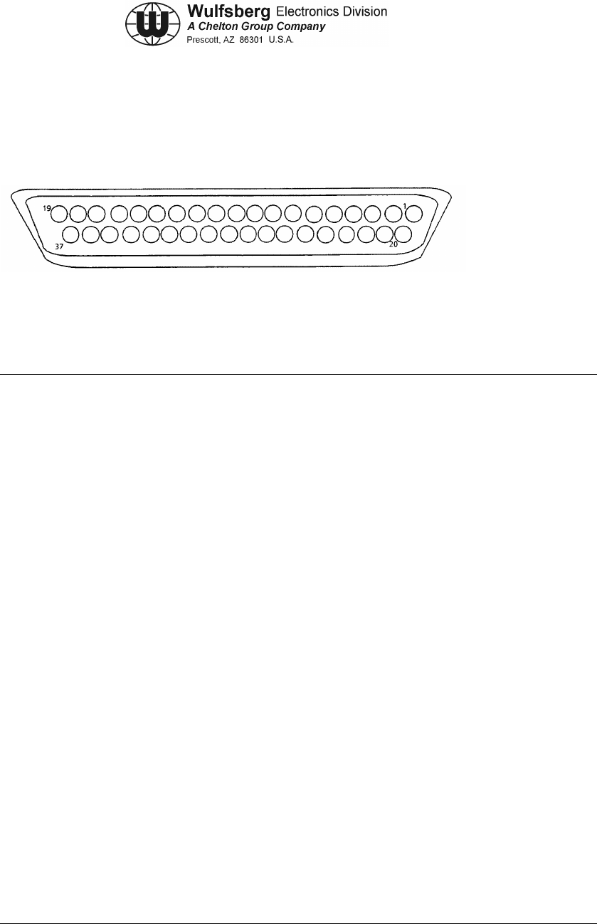
Figure 4-4. P501/P502 Connectors
(2) C-5000 Transceiver (RT-5000) Connector P501, P502.
PIN SIGNAL NAME PIN SIGNAL NAME
1 DIGITAL SHIELD 23 SPARE
2 CONTROL TX L 24 SPARE
3 ON/OFF 25 RESERVED OUT SPARE B
4 CONTROL TX H 26 VOICE AUDIO LO
5 CONTROL RX L 27 RESERVED OUPUT SPARE
6 SPARE 28 SPARE
7 IN SPARE NO 1 29 SHIELD
8 CONTROL RX H 30 MIC HI
9 SPARE 31 UNSQL MN RCV AUDIO
10 SPARE 32 SPARE
11 MIC LO/PTT 33 TX
12 SPARE 34 IN SPARE NO 3
13 VOICE AUDIO HI 35 SPARE
14 CIPHER/PLAIN 36 IN SPARE NO 2
15 SPARE 37 GROUND
16 PLAIN/CIPHER
17 TAKE CONTROL
18 EXT XMT AUDIO
19 GROUND
20 CONTROL GROUND
21 UNSQL GD RCV AUDIO
22 SPARE
Table 4-2. C-5000 Transceiver (RT-5000) Connector P501, P502 Pin Names

C-5000 COMMUNICATION MANAGEMENT CONTROLLER
INSTALLATION MANUAL
Page 4-14 Publication No. 150-041118
Section 4 – Electrical Installation Rev A
Sep 2001
Note: Verify that the C-5000 Serial RT Card is installed in for this interface.
(3) Digital Shield (Pin 1)
Shield ground connection for RS-422.
(4) Control TX L (Pin 2)
This output is the active low sense serial data output and meets EIA RS-485 voltage
levels. The data from this output goes to the RT-5000.
(5) On/Off (Pin 3)
When this output is pulled to ground, power is applied to the RT-5000.
(6) Control TX H (Pin 4)
This output is the active high sense serial data output and meets EIA RS-485 voltage
levels. The data from this output goes to the RT-5000.
(7) Control RX L (Pin 5)
This input is the active low sense serial data input, meets EIA RS-485 voltage levels, and
is tri-stated when the TAKE CONTROL line is grounded.
(8) Spare (Pin 6)
(9) In Spare #1 (Pin 7)
(10) Control RX H (Pin 8)
This input is the active high sense serial data input, meets EIA RS-485 voltage levels,
and is tri-stated when the TAKE CONTROL line is grounded.
(11) Spare (Pin 10)
(12) MIC LO/PTT (Pin 11)
(13) Spare (Pin 12)
Headset output for R/T.
(14) Voice Audio HI (Pin 13)
This is the high side differential audio input. It can drive a 150 Ohm load to 100 mW and
a 600 Ohm load to 25 mW. 3 dB bandwidth is 300 Hz to 3 kHz.
(15) Cipher/Plain (Pin 14)
30 mA to ground activates cipher; open is standard.

C-5000 COMMUNICATION MANAGEMENT CONTROLLER
INSTALLATION MANUAL
Publication No. 150-041118 Page 4-15
Rev A Section 4 –Electrical Installation
Sep 2001
(16) Spare (Pin 15)
(17) Plain/Cipher (Pin 16)
30 mA to ground is standard; open is cipher.
(18) Take Control (Pin 17)
Grounding tri-states RS-422 TX lines.
(19) EXT XMT Audio (Pin 18)
This output is the single ended extra wide band audio output. It has a nominal impedance
between 2k Ohms and 5k Ohms and a 3 dB bandwidth of 1 Hz to 40 kHz. The output is
adjustable from 0.1 Vrms to 1.5 Vrms and set to .6 Vrms.
(20) Ground (Pin 19)
Ground.
(21) Control Ground (Pin 20)
Ground connection to R/T.
(22) UNSQL GD RCV AUDIO (Pin 21)
Unsquelched guard receive audio input.
(23) Spare (Pin 22)
(24) Reserved Out Spare B (Pin 25)
(25) Voice Audio LO (Pin 26)
This is the low side differential audio input. It can drive a 150 Ohm load to 100 mW and a
600 Ohm load to 25 mW. 3 dB bandwidth is 300 Hz to 3 kHz.
(26) Reserved Out Spare A (Pin 27)
Spare output A.
(27) Shield (Pin 29)
Audio output shield ground connection.
(28) Mic HI (Pin 30)
This output is the standard 150 Ohm carbon microphone high output. The nominal output
is .25 Vrms and is adjustable over a range of .125 Vrms to 1.5 Vrms. The 3 dB bandwidth
is 100 Hz to 8.7 kHz for raw audio and 300 Hz to 3 kHz for processed audio per EIA
specifications. Unsquelched main receive audio input.

C-5000 COMMUNICATION MANAGEMENT CONTROLLER
INSTALLATION MANUAL
Page 4-16 Publication No. 150-041118
Section 4 – Electrical Installation Rev A
Sep 2001
(29) UNSQL MN RCV AUDIO (Pin 31)
(30) Spare (Pin 32)
(31) TX (Pin 33)
Grounding activates transmit.
(32) In Spare No. 3 (Pin 34)
(33) Spare (Pin 35)
(34) In Spare No. 2 (Pin 36)
(35) Control Ground (Pin 37)
Loss of this ground may disable the RT-5000 or cause intermittent function.
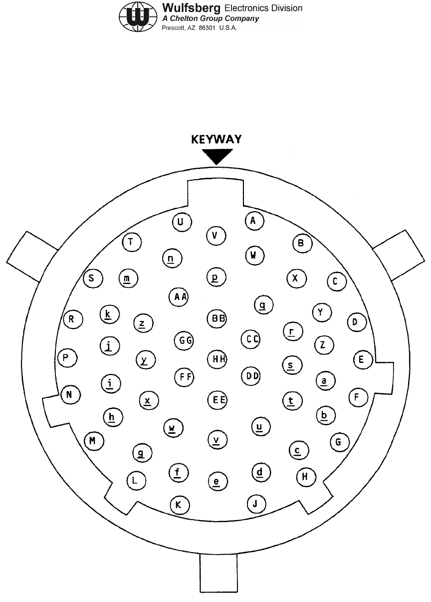
C-5000 COMMUNICATION MANAGEMENT CONTROLLER
INSTALLATION MANUAL
Publication No. 150-041118 Page 4-17
Rev A Section 4 –Electrical Installation
Sep 2001
C. RT-5000 Transceiver Installation Wiring Considerations
(1) J101 Connector
Figure 4-5 Connector J101

C-5000 COMMUNICATION MANAGEMENT CONTROLLER
INSTALLATION MANUAL
Page 4-18 Publication No. 150-041118
Section 4 – Electrical Installation Rev A
Sep 2001
(2) RT-5000 Transceiver Connector J101 Pin Names.
PIN SIGNAL NAME PIN SIGNAL NAME
A AUX AUDIO IN i GUARD AUDIO INHIBIT
B AUX SIDETONE j AUDIO HI
C RES SPARE A k AUDIO LO
D CONTROL GND m AUDIO SHIELD GND
E ANT RX H n EXTRA WB MAIN RX AUDIO
F ANT RX L p MAIN SQUELCH DISABLE
G ANT TX L q WIDE BAND MAIN RX AUDIO
H ANT TX H r DF ENABLE
J CONTROL RX H S DF AUDIO
K CONTROL RX L t XMIT INHIBIT
L CONTROL TXL U HOMING SIGNAL STRENGTH
m CONTROL TX H V MN RX 180 ENABLE
N DATA SHIELD GND w WIDE BAND GUARD RX AUDIO
P MAIN SQUELCH ANNUN x GD RX 180 ENABLE
R GUARD SQUELCH ANNUN y GUARD RX AUDIO
S RES SPARE B z TX 180 ENABLE
T RES SPARE C AA +27.5VDC A/C POWER
u RES SPARE D BB +27.5VDC A/C POWER
v RES SPARE E CC +27.5VDC A/C POWER
w ON/OFF DD +27.5VDC A/C POWER
x GUARD SQUELCH DISABLE EE A/C POWER GROUND
Y MIC HI FF A/C POWER GROUND
z MIC LO/PTT GG A/C POWER GROUND
a EXTERNAL PTT HH A/C POWER GROUND
bPTT OUTPUT
C SWITCHED +15V
d TX SWITCHED +15V
e SWITCHED +27.5V
f MAIN AUDIO INHIBIT
g EXTRA WIDE BAND AUDIO IN
h WIDE BAND AUDIO IN
Table 4-3. RT-5000 Transceiver Connector J101 Pin Names

C-5000 COMMUNICATION MANAGEMENT CONTROLLER
INSTALLATION MANUAL
Publication No. 150-041118 Page 4-19
Rev A Section 4 –Electrical Installation
Sep 2001
(3) RT-5000 Connector J101
(a) Aux Audio In (Pin A)
This input will take audio from an external source unit and add to the normal
transceiver audio.
(b) Aux Sidetone (Pin B)
This input will take alert tone audio from an external source and produce headset
sidetone.
(c) Key (Pin C)
This input is used to input MTM information.
(d) Control Gnd (Pin D)
This ground goes to the control head. Loss of this ground may disable the RT-5000
or cause intermittent function.
(e) Ant RX H (Pin E)
This output is the active high sense serial data output and meets EIA RS-485
voltage levels. The data from this output controls the RT-5000 antenna.
(f) Ant RX L (Pin F)
This output is the active low sense serial data output and meets EIA RS-485 voltage
levels. The data from this output controls the RT-5000 antenna.
(g) ANT TX L (Pin G)
This input is the active low sense serial data output and meets EIA RS-485 voltage
levels. The data from this input comes from the RT-5000 antenna.
(h) ANT TX H (Pin H)
This input is the active high sense serial data output and meets EIA RS-485 voltage
levels. The data from this input comes from the RT-5000 antenna.
(i) CONTROL RX H (Pin J)
This output is the active high sense serial data output, meets EIA RS-485 voltage
levels, and is tri-stated when the TAKE CONTROL line is grounded.
(j) CONTROL RX L (Pin K)
This output is the active low sense serial data output, meets EIA RS-485 voltage
levels, and is tri-stated when the TAKE CONTROL line is grounded.

C-5000 COMMUNICATION MANAGEMENT CONTROLLER
INSTALLATION MANUAL
Page 4-20 Publication No. 150-041118
Section 4 – Electrical Installation Rev A
Sep 2001
(k) CONTROL TX L (Pin L)
This input is the active low sense serial data input and meets EIA RS-485 voltage
levels. The data from this input comes from the C-5000.
(l) CONTROL TX H (Pin M)
This input is the active high sense serial data input and meets EIA RS-485 voltage
levels. The data from this input comes from the C-5000.
(m) DATA SHIELD GND (Pin N)
This ground shields lines E, F, J, and K.
(n) MAIN SQUELCH ANNUN (Pin P)
This output sinks 30 mA to ground when the main receiver signal-to-noise squelch
conditions are met.
(o) GUARD SQUELCH ANNUN (Pin R)
This output sinks 30 mA to ground when the guard receiver signal-to-noise squelch
conditions are met.
(p) RS232-RXD (Pin S)
This pin is used to transfer information to the MTM guard.
(q) RS232-TXD (Pin T)
This pin is used to transfer information to the MTM guard.
(r) RS232-CTS (Pin U)
This pin is used to transfer information to the MTM guard.
(s) Attenuator Control (Pin V)
When this input is pulled to ground, the RT-5000 will engage a 10 dB receive
attenuator in both main and crystal synthesized guard receivers.
(t) On/Off (Pin W)
When this input is pulled to ground, power is applied to the RT-5000.
(u) Guard Squelch Disable (Pin X)
When this input is pulled to ground, the guard squelch conditions are overridden.
(v) MIC HI (Pin Y)

C-5000 COMMUNICATION MANAGEMENT CONTROLLER
INSTALLATION MANUAL
Publication No. 150-041118 Page 4-21
Rev A Section 4 –Electrical Installation
Sep 2001
This input is the standard 150 Ohm carbon microphone high input. The nominal
input is .25 Vrms and is adjustable over a range of .125 Vrms to 1.5 Vrms. The 3 dB
bandwidth is 100 Hz to 8.7 kHz for raw audio and 300 Hz to 3 kHz for processed
audio per EIA specifications.
(w) MIC LO/PTT (Pin Z)
This input when pulled to ground, places the radio in transmit mode if the transmit
bit is set in the serial data stream. This input also forms the low side of the standard
150 Ohm carbon microphone.
(x) External PTT (Pin a)
The radio will remain in transmit mode when this input is pulled to ground.
(y) PTT Output (Pin b)
This output sinks 30ma to ground when the RT-5000 is transmitting.
(z) Switched +15 V (Pin c)
This output is capable of supplying +15 V ± 1.5 V at 500 mA.
(aa) TX SWITCHED +15V (Pin d)
When the RT-5000 is placed in transmit mode, this output supplies +15V ±2.5V at a
maximum of 100 mA.
(bb) SWITCHED +27.5V (Pin e)
This output is capable of supplying unregulated +27.5V at 500 mA.
(cc) MAIN AUDIO INHIBIT (Pin f)
When this input is pulled to ground, the main receiver audio is disabled.
(dd) EXTRA WIDE BAND AUDIO IN (Pin g)
This input is the single ended extra wide band audio input. It has a nominal
impedance between 2k Ohms and 5k Ohms and a 3 dB bandwidth of I Hz to 40
kHz. The input is adjustable from 0.1 Vrms to 1.5 Vrms and set to .6 Vrms.
(ee) WIDE BAND AUDIO IN (Pin h)
This input is the single ended wide band audio input. It has a nominal impedance
between 2k Ohms and 5k Ohms and a 3 dB bandwidth of 1 Hz to 27.5 kHz. The
input is adjustable from .1 Vrms to 1.5 Vrms and set to .6 Vrms.
(ff) GUARD AUDIO INHIBIT (Pin i)
When this input is pulled to ground, the guard receiver audio is disabled.

C-5000 COMMUNICATION MANAGEMENT CONTROLLER
INSTALLATION MANUAL
Page 4-22 Publication No. 150-041118
Section 4 – Electrical Installation Rev A
Sep 2001
(gg) AUDIO HI (Pin j)
This is the high side differential audio output. It can drive a 150 Ohm load to 100
mW and a 600 Ohm load to 25 mW. 3 dB bandwidth is 300 Hz to 3 kHz.
(hh) AUDIO LO (Pin k)
This is the low side differential audio output. It can drive a 150 Ohm load to 100 mW
and a 600 Ohm load to 25 mW. 3 dB bandwidth is 300 Hz to 3 kHz.
(ii) AUDIO SHIELD GND (Pin m)
This ground is for shielding the audio outputs.
(jj) EXTRA WIDE BAND MAIN RX AUDIO (Pin n)
This output is the single ended extra wide band audio output. It is capable of driving
a 2k Ohm impedance and has a 3 dB bandwidth of 1 Hz to 40 kHz. The output is
adjustable from .1 Vrms to 1.5 Vrms and set to .6 Vrms.
(kk) MAIN SQUELCH DISABLE (Pin p)
When this input is pulled to ground, the main squelch conditions are overridden.
(ll) WIDE BAND MAIN RX AUDIO (Pin q)
This output is the single ended audio output. It is capable of driving a 2k Ohm
impedance and has a bandwidth of 1 Hz to 27.5 kHz.
(mm) DF ENABLE (Pin r)
Grounding this input enables the DF audio output.
(nn) DF AUDIO (Pin s)
This output produces an output proportional to the AM signal. The output has a 3 dB
bandwidth of 1Hz to 10 kHz. The output will drive a 2k Ohm impedance. The output
is adjustable from. 1 Vrms to 1.5 Vrms and set to .6 Vrms.
(oo) RS232-RTS (Pin t)
This pin is used to transfer information to the MTM guard.
(pp) HOMING SIGNAL STRENGTH (Pin u)
This output produces an output based on the signal strength that varies between 0
and 8 VDC, and is capable of driving a 2k Ohm load. This signal has a 3 dB
bandwidth between DC and 50 Hz.
(qq) MN RX 180 ENABLE (Pin v)

C-5000 COMMUNICATION MANAGEMENT CONTROLLER
INSTALLATION MANUAL
Publication No. 150-041118 Page 4-23
Rev A Section 4 –Electrical Installation
Sep 2001
Grounding this input causes 180 degrees of phase shift in the main received audio.
This phase shift may be required when using an external encryption device.
(rr) WIDE BAND GUARD RX AUDIO (Pin w)
This output is the single ended wide band guard audio output. It is capable of driving
a 2k Ohm impedance and has a 3 dB bandwidth of 1 Hz to 27.5 kHz. The output is
adjustable from .1 Vrms to 1.5 Vrms and set to .6 Vrms.
(ss) GD RX 180 ENABLE (Pin x)
Grounding this input causes 180 degrees of phase shift in the guard received audio.
This phase shift may be required when using an external encryption device.
(tt) GUARD RX AUDIO (Pin y)
This output is the single ended guard audio output. It is capable of driving a 2k Ohm
impedance and has a 3 dB bandwidth of 1 Hz to 3kHz. The output is adjustable from
.1 Vrms to 1.5 Vrms and set to .6 Vrms.
(uu) TX 180 ENABLE (Pin z)
Grounding this input causes 180 degrees of phase shift in the transmitted audio.
This phase shift may be required when using an external encryption device.
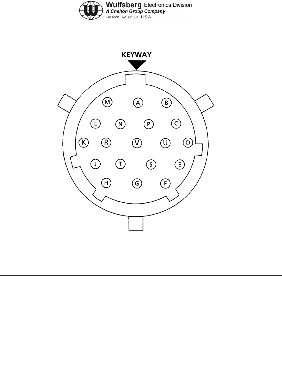
C-5000 COMMUNICATION MANAGEMENT CONTROLLER
INSTALLATION MANUAL
Page 4-24 Publication No. 150-041118
Section 4 – Electrical Installation Rev A
Sep 2001
PIN SIGNAL NAME PIN SIGNAL NAME
A RECEIVE HI L S0
B RECEIVE LO M GROUND
C TRANSMIT HI N
D TRANSMIT LO P GROUND
E GROUND R
FSS3
GTNC
H GROUND U NC
JNC V
KNC
Figure 4-6. FC-50 / FC-550 / FC-5000 Connector J1
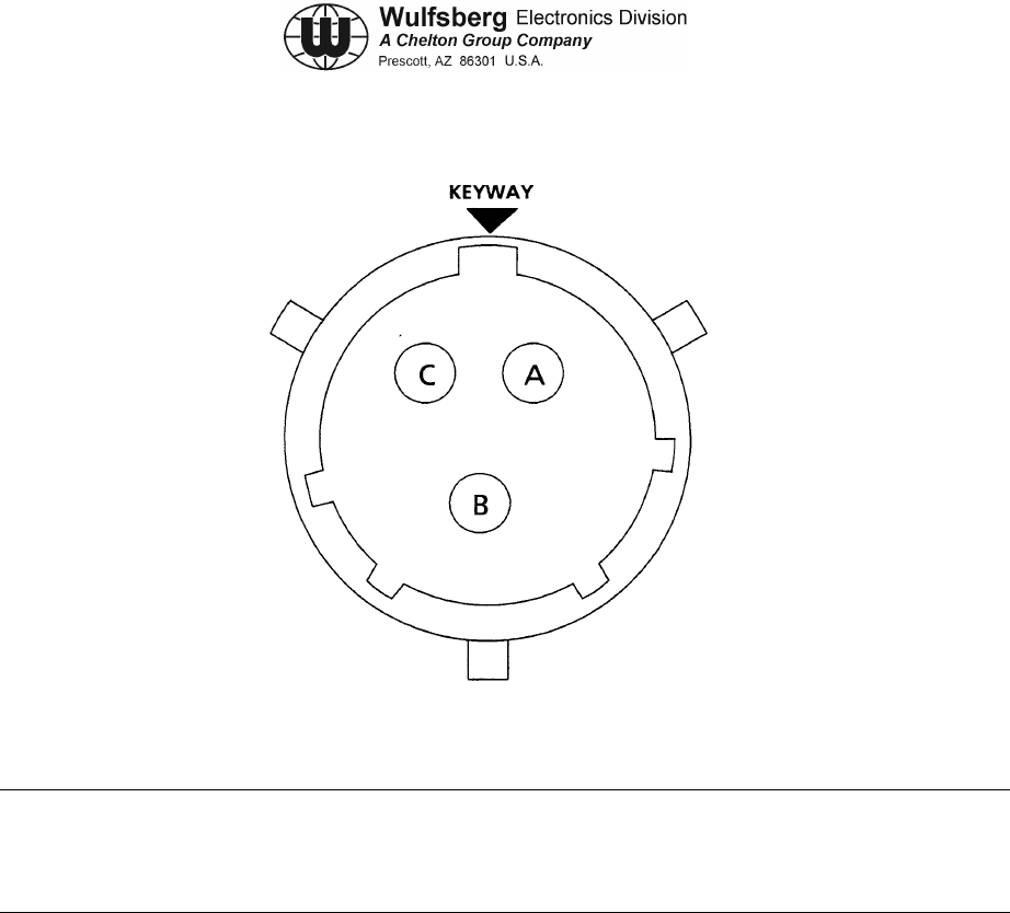
C-5000 COMMUNICATION MANAGEMENT CONTROLLER
INSTALLATION MANUAL
Publication No. 150-041118 Page 4-25
Rev A Section 4 –Electrical Installation
Sep 2001
PIN SIGNAL NAME PIN SIGNAL NAME
A+27.5 VDC
B DC RETURN
CGND
Figure 4-7. FC-50 / FC-550 / FC-5000 Connector J2
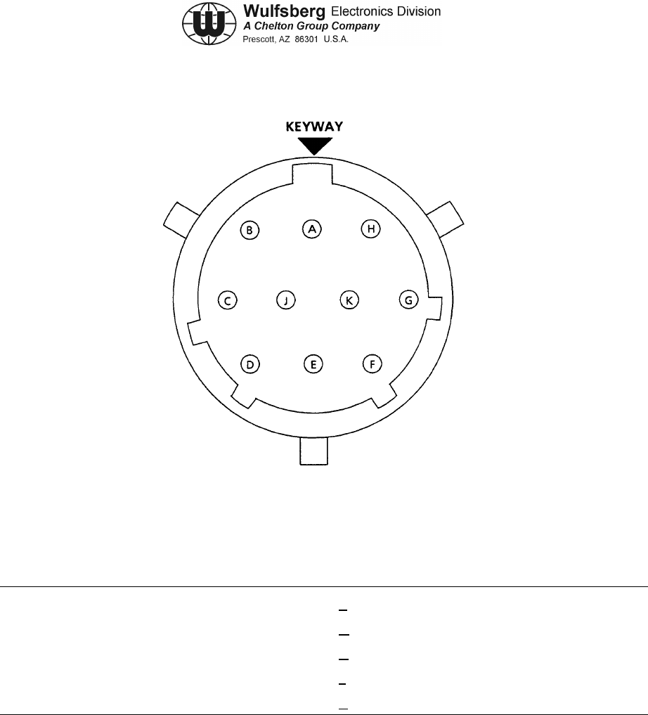
C-5000 COMMUNICATION MANAGEMENT CONTROLLER
INSTALLATION MANUAL
Page 4-26 Publication No. 150-041118
Section 4 – Electrical Installation Rev A
Sep 2001
NOTE: FC-50 Connector J3 connects to AT-50/AT-51 antennas. These pins provide proprietary
channeling information to the antenna.
PIN SIGNAL NAME PIN SIGNAL NAME
A Proprietary F Proprietary
B Proprietary G Proprietary
C Proprietary H Proprietary
D Proprietary J Proprietary
E Proprietary K Proprietary
Figure 4-8. FC-50 / FC-550 / FC-5000 Connector J3

C-5000 COMMUNICATION MANAGEMENT CONTROLLER
INSTALLATION MANUAL
Publication No. 150-041118 Page 4-27
Rev A Section 4 –Electrical Installation
Sep 2001
Remove this page and insert 152-140131 Sheet 1 of 4 (Figure 4-9)

C-5000 COMMUNICATION MANAGEMENT CONTROLLER
INSTALLATION MANUAL
Page 4-28 Publication No. 150-041118
Section 4 – Electrical Installation Rev A
Sep 2001
Remove this page.

C-5000 COMMUNICATION MANAGEMENT CONTROLLER
INSTALLATION MANUAL
Publication No. 150-041118 Page 4-29
Rev A Section 4 –Electrical Installation
Sep 2001
Remove this page and insert 152-140131 Sheet 2 of 4 (Figure 4-9)

C-5000 COMMUNICATION MANAGEMENT CONTROLLER
INSTALLATION MANUAL
Page 4-30 Publication No. 150-041118
Section 4 – Electrical Installation Rev A
Sep 2001
Remove this page.

C-5000 COMMUNICATION MANAGEMENT CONTROLLER
INSTALLATION MANUAL
Publication No. 150-041118 Page 4-31
Rev A Section 4 –Electrical Installation
Sep 2001
Remove this page and insert 152-140131 Sheet 3 of 4 (Figure 4-9)

C-5000 COMMUNICATION MANAGEMENT CONTROLLER
INSTALLATION MANUAL
Page 4-32 Publication No. 150-041118
Section 4 – Electrical Installation Rev A
Sep 2001
Remove this page.

C-5000 COMMUNICATION MANAGEMENT CONTROLLER
INSTALLATION MANUAL
Publication No. 150-041118 Page 4-33
Rev A Section 4 –Electrical Installation
Sep 2001
Remove this page and insert 152-140131 Sheet 4 of 4 (Figure 4-9)

C-5000 COMMUNICATION MANAGEMENT CONTROLLER
INSTALLATION MANUAL
Page 4-34 Publication No. 150-041118
Section 4 – Electrical Installation Rev A
Sep 2001
Remove this page.
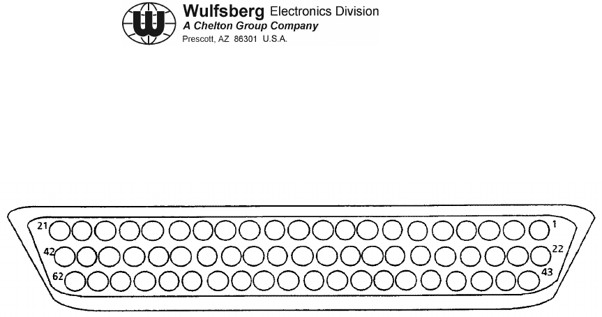
C-5000 COMMUNICATION MANAGEMENT CONTROLLER
INSTALLATION MANUAL
Publication No. 150-041118 Page 4-35
Rev A Section 4 –Electrical Installation
Sep 2001
D. C-5000 Communication Management Controller Installation Wiring Considerations
(1) C-5000 Transceiver (FLEXCOMM I) Connector P501 or P502.
Figure 4-10. C-5000 Transceiver (FLEXCOMM I) Connector P501 or P502

C-5000 COMMUNICATION MANAGEMENT CONTROLLER
INSTALLATION MANUAL
Page 4-36 Publication No. 150-041118
Section 4 – Electrical Installation Rev A
Sep 2001
(2) C-5000 Transceiver (FLEXCOMM I) Connector P501 or P502.
PIN SIGNAL NAME PIN SIGNAL NAME
1 TONE C LINE 32 4 MHZ CHN LINE
2 TX PWR LITE 33 MIC LO/PTT
3 0.08 MHZ CHN LINE 34 0.01 MHZ CHN LINE
4 120 MHZ CHN LINE 35 0.005 MHZ CHN LINE
5 80 MHZ CHN LINE 36 RESRV SPARE GUARD TONE
ENABLE
6 TONE E LINE (MSB) 37 40 MHZ CHN LINE
7 SPARE #2 38 CIPHER/PLAIN
8ON/OFF 39TX
9 10.0025 MHZ CHN LINE 40 PLAIN/CIPHER
10 2 MHZ CHN LINE 41 AUDIO LO
11 MIC HI 42 MN VOL SET
12 TONE A LINE (LSB) 43 TONE B LINE
13 MAIN RCVR AUDIO DISABLE 44 0.04 MHZ CHN LINE
14 TX PWR SELECT 45 EXTERNAL ENCODE IN
15 CHN MEMORY DISCRETE NO. 2 46 DF DISABLE
16 CHN MEMORY DISCRETE NO. 3 47 TAKE CONTROL
17 CHN MEM DISCRETE NO. 4 48 GUARD SQUELCH LITE
18 SPARE #3 49 0.1 MHZ CHN LINE
19 GD SELECT 50 GD VOL SET
20 ZEROIZE 51 800 MHZ CHN LINE
21 UNSQUELCHED MAIN AUDIO 52 0.4 MHZ CHN LINE
22 SHIELD 53 0.2 MHZ CHN LINE
23 MAIN TONE ENABLE 54 GUARD RCVR AUDIO DISABLE
24 SPARE #1 55 0.8 MHZ CHN LINE
25 SQUELCH DISABLE 56 CHN MEMORY DISCRETE NO. 1
26 10 MHZ CHN LINE 57 0.02 MHZ CHN LINE
27 100 MHZCHN LINE 58 MAIN SQUELCH LITE
28 1400 MHZ CHN LINE 59 CHN MEM DISCRETE NO. 5
29 TONE D LINE 60 UNSQUELCHED GUARD AUDIO
30 1 MHZ CHN LINE 61 AUDIO HI
31 8 MHZ CHN LINE 62 AUX GND NO. 20 AWG
Table 4-4. C-5000 Transceiver (FLEXCOMM I) Connector P501 or P502

C-5000 COMMUNICATION MANAGEMENT CONTROLLER
INSTALLATION MANUAL
Publication No. 150-041118 Page 4-37
Rev A Section 4 –Electrical Installation
Sep 2001
E. C-5000 Transceiver Interface FLEXCOMM Transceivers, RT-30, RT-118, RT-138,
RT-138F, RT-406F and RT-450
(1)
Figure 4-11.
(2)
Table 4-5.
(3) CHANNEL LINES (Pins 3, 4, 5, 9, 10, 26, 27, 28, 30, 31, 32, 34, 35, 37, 44, 49, 51,
52, 53, 55, 57)
The channeling lines use BCD (Binary Coded Decimal) negative logic to control the
Transceiver channel frequency. These lines are grounded by the Control Unit to channel
the Transceiver to the selected frequency. The channel is determined by adding the
weighted value of each line. To channel a transceiver to 157.135 MHz, the following
lines would be grounded:
100 MHz line
40 MHz line
10 MHz line
4MHz line
2MHz line
1MHz line
0.1 MHz line
0.02 MHz line
0.01 MHz line
0.005 MHz line
157.135 MHz
Unselected channel lines should exceed +8 Vdc.
(4) TONE A, B, C, D, E (Pins 1, 6, 12, 29, 43)
These lines are used to provide pre-programmed control of a synthesized CTCSS
encoder/decoder in the transceiver. The order of the lines follows a binary code with E
the most significant bit and A the least significant. Logic "0" is a ground line and logic "1"
must be greater than 8 volts. Refer to Section 6, Preset Channel Programming, for
information on programming tones and Table 6-2, Section 6, for available frequencies.
(5) MAIN TONE ENABLE (Pin 23)
This line, when grounded, will activate the continuous tone controlled squelch system
(CTCSS) for either transmit tone encode or main receiver tone decode. The tone
frequency is determined by the Tone A, B, C, D, E lines.
(6) ON/OFF (Pin 8)

C-5000 COMMUNICATION MANAGEMENT CONTROLLER
INSTALLATION MANUAL
Page 4-38 Publication No. 150-041118
Section 4 – Electrical Installation Rev A
Sep 2001
This line, when grounded, will activate the 28 V system relay and provide +27.5 Vdc
aircraft power to the Transceiver.
(7) MAIN RX AUDIO DISABLE (Pin 13)
Grounding this line mutes Main Receiver audio, but does not affect sidetone or Guard
Receiver audio. The main squelch test function is disabled, yet the main channel
indicator shows channel activity.
(8) GUARD RX AUDIO DISABLE (Pin 54)
Grounding this line disables guard audio, but does not affect Main Receiver or sidetone
audio. The guard channel indicator continues to indicate guard channel activity.
(9) MAIN SQUELCH LITE (Pin 58)
The Transceiver pulls this line low to activate the main squelch annunciator in the Control
Unit.
(10) GUARD SQUELCH LITE (Pin 48)
The Transceiver Guard Module pulls this line low to activate the guard squelch
annunciator in the Control Unit.
(11) TX POWER LITE (Pin 2)
The transceiver pulls this line low to activate the transmit annunciator in the Control Unit.
(12) SQUELCH DISABLE (Pin 25)
This line is grounded by the test (squelch disable) button on the Control Unit. It opens
the squelch gate for the Main or Guard Receiver unless:
• In the Transmit Mode.
• Main or Guard RCVR Audio is disabled by the Control Unit.
• Frequency Synthesizer not locked (Main only).
In addition, the Main and Guard Squelch indicators will activate unless disabled by the
following conditions:
• Transmit Mode.
• Frequency Synthesizer not locked (Main only)
(13) RESERVED SPARE (Pins 15, 16, 56)
These lines provide a user programmable combination of discrete electronic switches for
each channel. Each channel memory discrete state may differ between transmit and
receive on any channel. These outputs are programmed when the channel information
and tone code information are entered into the Control Unit.
Some possible uses for these include:

C-5000 COMMUNICATION MANAGEMENT CONTROLLER
INSTALLATION MANUAL
Publication No. 150-041118 Page 4-39
Rev A Section 4 –Electrical Installation
Sep 2001
• Antenna switching
• External encoder enable (disable).
• External decoder enable (disable).
• Any functional or equipment switching associated with a given channel.
These switch closures may be combined with a digital decoder to expand the capabilities.
These switches are open collector drivers. Open switch voltages may not exceed +30 V,
and in the closed condition, the switches will sink up to 40 mA.
(14) CONTROL UNIT GROUND (Pin 62)
This line provides signal ground reference for the Control Unit. (The Control Unit
electronics are isolated from the chassis).
(15) AUDIO HI AND LO (Pin 41, 61)
These lines provide a balanced 600 Ohm audio output from the Transceiver and are set
for 100 mW into a 600 Ohm load. (7.75 Vrms)
(16) MIC HI AND LO/PTT (Pin 11, 33)
These lines are used for voice modulation and to enable the transmitter. Mic sensitivity is
factory set for an input of 0.25VRMS at 1 kHz to provide ±3 kHz FM deviation, 85% AM
modulation. The MIC LO/PTT line activates the transmitter when grounded and disables
the receiver outputs.
(17) TX (Transceiver Or Control, Pin 39)
The Transceiver and control pull their respective TX lines low during transmit to provide
TX information to auxiliary equipment.
(18) EXTERNAL ENCODE IN (Pin 45)
This line provides for modulating the transmitter from external encoding devices in the
frequency range of 60 to 3000Hz. Inputs of 1.0 Vrms will yield approximately ±2.5 to
±3 kHz deviation. The RT-138F and RT-406F Frequency Range is approximately 1Hz to
6 kHz.
(19) UNSQUELCHED MAIN AUDIO (Pin 21)
This line provides unsquelched audio from the Main Receiver. The frequency response
is flat from 60 Hz to 5 kHz. A received signal of 1 kHz tone at ±3 kHz deviation will
produce approximately 0.6 Vrms into a 20k Ohm load. The RT-138F and RT-406F
Frequency Range is approximately 1 Hz to 6 kHz.
(20) UNSQUELCHED GUARD AUDIO (Pin 60)
This line provides an unsquelched audio output of the Guard Receiver for use with
external audio decoders. The frequency response is approximately flat from 60 Hz to

C-5000 COMMUNICATION MANAGEMENT CONTROLLER
INSTALLATION MANUAL
Page 4-40 Publication No. 150-041118
Section 4 – Electrical Installation Rev A
Sep 2001
5 kHz. Standard 3 kHz modulation of a 1 kHz tone will produce approximately 0.6 Vrms
into a 20k Ohm load.
(21) MAIN AUDIO INHIBIT (Pin 13)
This line will mute Main Receiver audio when grounded and can be paralleled for use
with external decoders. The squelch test will open the audio squelch gate regardless of
the status of this line.
(22) GUARD AUDIO INHIBIT (Pin 54)
This line will mute Guard Receiver audio when grounded and can be paralleled for use
with external decoders. The squelch test will open the audio squelch gate regardless of
the status of this line.
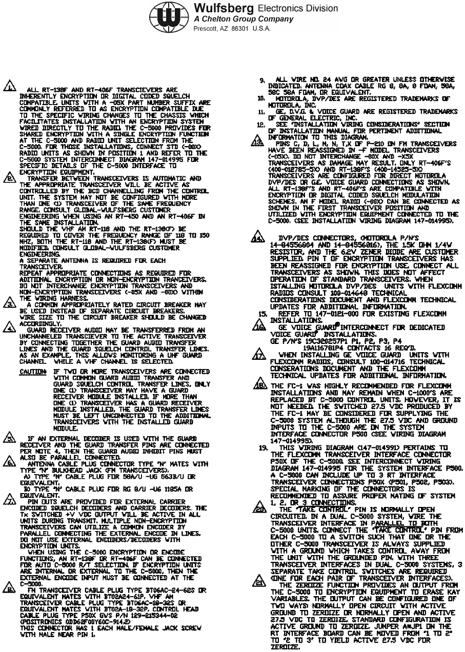
C-5000 COMMUNICATION MANAGEMENT CONTROLLER
INSTALLATION MANUAL
Publication No. 150-041118 Page 4-41
Rev A Section 4 –Electrical Installation
Sep 2001
Figure 4-12a. FLEXCOMM Transceivers Installation Wiring Diagram (Sheet 1 of 3)
RT-30, RT-118, RT-138, RT-138F, RT-450 and RT-406F
(Dwg No 147-014991, Rev B)

C-5000 COMMUNICATION MANAGEMENT CONTROLLER
INSTALLATION MANUAL
Page 4-42 Publication No. 150-041118
Section 4 – Electrical Installation Rev A
Sep 2001
This page intentionally left blank.

C-5000 COMMUNICATION MANAGEMENT CONTROLLER
INSTALLATION MANUAL
Publication No. 150-041118 Page 4-43
Rev A Section 4 –Electrical Installation
Sep 2001
Remove this page and insert 147-014991 Sheet 2 of 3 (Figure 4-12b)

C-5000 COMMUNICATION MANAGEMENT CONTROLLER
INSTALLATION MANUAL
Page 4-44 Publication No. 150-041118
Section 4 – Electrical Installation Rev A
Sep 2001
Remove this page.

C-5000 COMMUNICATION MANAGEMENT CONTROLLER
INSTALLATION MANUAL
Publication No. 150-041118 Page 4-45
Rev A Section 4 –Electrical Installation
Sep 2001
Remove this page and insert 147-014991 Sheet 3 of 3 (Figure 4-12c)

C-5000 COMMUNICATION MANAGEMENT CONTROLLER
INSTALLATION MANUAL
Page 4-46 Publication No. 150-041118
Section 4 – Electrical Installation Rev A
Sep 2001
Remove this page.
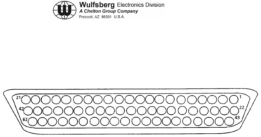
C-5000 COMMUNICATION MANAGEMENT CONTROLLER
INSTALLATION MANUAL
Publication No. 150-041118 Page 4-47
Rev A Section 4 –Electrical Installation
Sep 2001
F. C-5000 Transceiver Interface, RT-9600, RT-9600F, RT-7200 Transceivers
(1) Connector P501/P502
Figure 4-13. Connector P501/P502

C-5000 COMMUNICATION MANAGEMENT CONTROLLER
INSTALLATION MANUAL
Page 4-48 Publication No. 150-041118
Section 4 – Electrical Installation Rev A
Sep 2001
(2) C-5000 Transceiver (RT-9600(F)/7200) Connector P50X (P501, P502, or P503)
PIN SIGNAL NAME PIN SIGNAL NAME
1 TONE SELECT C 32 4 MHZ
2 TX POWER ANNUNCIATE 33 PTT
3 0.08 MHZ 34 0.01 MHZ
4 20 MHZ 35 0.005 MHZ
5 80 MHZ 36 GUARD TONE ENABLE
6 TONE E 37 RT7200: 40 MHZ, RT9600(F): .0025
MHZ, RT9600F w/DVP/DES: 40 MHz
7 SPARE #2 38 RT7200, RT9600(F):CIPHER/PLAIN
RT9600F w/DVP/DES: CH PVT/STD
8 ON/OFF 39 RT7200, RT9600(F): TX RT9600F
w/DVP/DES: RAD PTT
9 RT7200: 40 MHZ, RT9600(F): .0025
MHZ, RT960OF w/DVP/DES:
.002MHZ
40 PLAIN/CIPHER
10 2 MHZ 41 AUDIO LO
11 MIC HI 42 MAIN VOLUME
12 TONE SELECT A 43 TONE SELECT B
13 MAIN AUDIO INHIBIT 44 0.04 MHZ
14 TX PWR SELECT 45 EXTERNAL CTCSS ENCODE IN
15 CHN MEMORY DISCRETE NO. 2 46 DF DISABLE
16 CHN MEMORY DISCRETE NO. 3 47 TAKE CONTROL
17 CHN MEMORY DISCRETE NO. 4 48 GUARD SQUELCH ANNUNCIATE
18 SPARE #3 49 0.1 MHZ
19 GUARD SELECT 50 GUARD VOLUME
20 ZEROIZE 51 800 MHZ
21 UNSQUELCHED MAIN AUDIO 52 0.4 MHZ
22 SHIELD 53 0.2 MHz
23 TONE SELECT D 54 EXTERNAL GUARD AUDIO INHIBIT
24 SPARE #1 55 0.8 MHZ
25 SQUELCH DISABLE 56 CHN MEMORY DISCRETE NO. 1
26 10 MHZ 57 0.02 MHz
27 100 MHZ 58 MAIN SQUELCH ANNUNCIATE
28 400 MHZ 59 CHN MEM DISCRETE NO. 5
29 TONE D 60 UNSQUELCHED GUARD AUDIO
30 1 MHz 61 AUDIO HI
31 8 MHZ 62 CONTROL GROUND 22 AWG
Table 4-6. C-5000 Transceiver (RT-9600(F)/7200) Connector P50X (P501, P502, or P503)

C-5000 COMMUNICATION MANAGEMENT CONTROLLER
INSTALLATION MANUAL
Publication No. 150-041118 Page 4-49
Rev A Section 4 –Electrical Installation
Sep 2001
(3) AUDIO AND SIDETONE HI AND LO (Pins 13, 14, 15 and 16)
These wires are provided separately for those systems that have separate transmitter
sidetone circuits. They should be paralleled when driving a speaker directly. 10 Watt
audio rated transceivers are not accommodated. In the case of the 100 mW
transceivers, the audio and sidetone outputs (output impedance of 600 Ohms) must be
set for 7.8 Vrms into 600 Ohms.
(4) DF DISABLE (Pin 54)
This line will disable the linear IF inside the unit and provide superior squelch action and
sensitivity when connected airframe ground. It should be permanently grounded at the
mounting rack when DF equipment is not installed in the aircraft. If used with DF
equipment, this line must be open during Direction Finding operations.
(5) DF AUDIO (Pin 19)
Provides an audio output for use with DF equipment requiring AM receiver response.
With an output impedance of 500 Ohms, the DF Audio output can supply 400 mVrms
open circuit with an RF signal modulated 50% at 1000 Hz.
When the RT-7200 or RT-9600(F) is used in conjunction with the Collins DF301E
automatic Direction Finder, knowledge of the Transceiver modulation phase delay at
5.68 kHz is necessary for proper DF301E compensation. This phase information is found
on a label on the rear panel of the RT-7200, or RT-9600, RT-9600F.
For DF or ADF systems designed to be used in conjunction with FM receivers, use
UNSQUELCHED MAIN AUDIO as the audio connection from the transceiver to the DF or
ADF unit.
(6) UNSQUELCHED MAIN AUDIO (Pin 12)
Buffered output of the main FM receiver, unaffected by squelch action. Provided for use
with external audio decoders. Standard modulation produces 0.58 Vrms into 1k Ohm or
greater impedance. Do not load this output with less than 600 Ohms.
(7) UNSQUELCHED GUARD AUDIO (Pin 30)
Buffered output for the guard receiver, unaffected by squelch action. Provided for use
with external audio decoders. Standard modulation produces 0.58 Vrms into 1k Ohm or
greater impedance. Do not load this output with less than 600 Ohms.
(8) MAIN AUDIO INHIBIT (Pin 26)
When grounded, will mute audio outputs from the main receiver.
(9) EXTERNAL GUARD AUDIO INHIBIT (Pin 25)
When grounded, will mute audio outputs for the guard receiver.

C-5000 COMMUNICATION MANAGEMENT CONTROLLER
INSTALLATION MANUAL
Page 4-50 Publication No. 150-041118
Section 4 – Electrical Installation Rev A
Sep 2001
(10) EXTERNAL CTCSS TONE IN (Pin 18)
Provision for modulating the transmitter with audio outside the normal audio frequency
range of 300 to 3000 Hz. Approximately 0.3 Vrms will give 5 kHz deviation.
(11) TRANSMITTER POWER SELECT (Pin 27)
When used with control units not providing transmitter power selector switches,
grounding this line at the mounting rack will provide 10 watts of RF output power. The
C-920 has this line grounded inside the control unit and will provide 10 watts when used.
(12) 14V SWITCHED (Pins 65 And 66)
Provision for switched 14 V power from the RT-7200/RT-9600. These pins will provide
14 Vdc. Exercise caution not to exceed a combined current drain of 500 mA from pins 65
and 66.
(13) PTT OUT (Pin 64)
May be used to key external accessories such as Tone Encoders. This pin is grounded
through the microphone PTT switch.

C-5000 COMMUNICATION MANAGEMENT CONTROLLER
INSTALLATION MANUAL
Publication No. 150-041118 Page 4-51
Rev A Section 4 –Electrical Installation
Sep 2001
Remove this page and insert 147-014992 Sheet 1 of 1 (Figure 4-14.)

C-5000 COMMUNICATION MANAGEMENT CONTROLLER
INSTALLATION MANUAL
Page 4-52 Publication No. 150-041118
Section 4 – Electrical Installation Rev A
Sep 2001
Remove this page.

C-5000 COMMUNICATION MANAGEMENT CONTROLLER
INSTALLATION MANUAL
Publication No. 150-041118 Page 4-53
Rev A Section 4 –Electrical Installation
Sep 2001
FLEXCOMM II
COMPONENT UNIT
CONNECTOR MATING
CONNECTOR
C-5000
System Interface
Board P500 WED PN
129-214800-01 D-Sub (62 Pin, with backshell and two male
jackscrews), POSITRONICS PN
ODD62F00Y60C-914.1 (129-215344-01)
R/T Board P501 or P502
RT-5000 WED PN
129-217474-01 D-Sub (37 Pin, with backshelI and one each
female and male jackscrews), POSITRONICS
PN ODD62F00Y60C-914.2 (129-217474-01)
FLEXCOMM I, RT-
9600(F),
RT-7200 P50X
WED PN
129-214800-02 D-Sub (62 Pin, with backshell and one each
female and male jackscrews), POSITRONICS
PN ODD62F00Y60C-914.2 (129-215344-02)
RT-5000 J101
J102
J103
PN 129-216657-01 (PT06SE-22-55S-SR)
“TNC” UP
“TNC” Type
“N” Type
“N” Type
AT-50/AT-51 “N” Type
DC Connector, PN 129-217323-01
(PT06SE-12-10S-SR)
FC-50 J1
J2
J3
PN 129-217321-01 (PT06SE-14-19S-SR)
PN 129-217324-01 (PT06SE-8-33S-SR,
3 Pin Connector)
PN 129-214346-01 (PT06SE-12-10P-SR)
AT-400 “N” for RG-58 Right Angle, PN 129-016858-01
“N” for RG-58 Straight, PN 129-016858-02
AT-140 “N” for RG-58 Right Angle, PN 129-016858-01
“N” for RG-58 Straight, PN 129-016858-02
Note: Numbers in parentheses are Wulfsberg Part numbers. Equivalent connectors by
other manufacturers may be substituted.
Table 4-7. Connectors Used

C-5000 COMMUNICATION MANAGEMENT CONTROLLER
INSTALLATION MANUAL
Page 4-54 Publication No. 150-041118
Section 4 – Electrical Installation Rev A
Sep 2001
This page intentionally left blank.

C-5000 COMMUNICATION MANAGEMENT CONTROLLER
INSTALLATION MANUAL
Publication No. 150-041118 Page 5-1
Rev. A Section 5 – Configuration and Programming
Sep 2001
Section 5 – Configuration and Programming
Introduction
The Wulfsberg C-5000 Communication Management Controller (CMC) is a microprocessor-based control head
device that controls one or two Wulfsberg transceivers. The C-5000 supports the full line of Wulfsberg
FLITECOMM, FLEXCOMM I, and FLEXCOMM II transceivers. This manual is intended to quickly instruct the
user on the basic operations of the C-5000 and also outline the advanced operations that set the C-5000 apart from
any other communication device.
Features
The C-5000 provides a host of powerful features, including
• Controls Wulfsberg RT-5000, RT-406F, RT-450, RT-138(F), RT-30, RT-9600(F) and RT-7200 transceivers.
• 350 preset channels, programmable from the front panel or using Wulfsberg’s Remote Programmer software.
• Users can dial in frequencies, PL tones, and transmit power on two “manual” channels.
• Advanced multi-radio modes, such as Simulcast, Relay, Repeater, and Relay-Simulcast.
• Control encryption functions embedded in the RT-5000 transceiver such as P25 Digital Modulation and
encryption with Over the Air Rekey (OTAR) capability.
Transceiver Overview
The C-5000 provides support for the Wulfsberg FLITECOMM, FLEXCOMM I, and FLEXCOMM II transceivers.
It is very important that users know how many radios and what type are connected to the C-5000 since transceivers
have very different capabilities and features. Here is a summary of the supported transceivers and their capabilities.
FLEXCOMM II
This product line consists of the RT-5000 AM/FM transceivers covering the 29.7 to 960 MHz frequency range. The
optional Guard Receiver can be specified as a single channel crystal guard (available in three frequency ranges), a
29.7 – 960 MHz receiver capable of being programmed with two Guard channels, or a receiver with one or two
modules capable of RT-5000’s are equipped with CTCSS and DCS tones on both the Main and Guard Receivers.
The MTM Guard variant of the RT-5000 adds support for P25 and Trunking channels, with encryption and over-the-
air-rekey (OTAR) capability.
FLEXCOM I
This product line currently consists of the RT-30, RT-138F, and RT-406F transceivers. The C-5000 also supports
the RT-118, RT-138, and RT-450 transceivers, which are no longer manufactured but remain in wide use. The RT-
30, RT-138F, and RT-406F FM transceivers cover the 29.7 to 49.99 MHz, 138.0 to 173.9975 MHz, and 406.0 to
511.9975 MHz frequency ranges, respectively. These transceivers can be specified with a single-channel, crystal-
controlled, Guard Receiver that operates on a customer-specified frequency. An optional Guard Receiver CTCSS
decoder with programmable Guard Receiver tone can also be specified.
Page 5-2 Publication No. 150-041118
Section 5 – Configuration and Programming Rev. A
Sep 2001
FLITECOMM
This product line is no longer manufactured, but remains in wide use. It consisted of the RT-7200, RT-9600, and
RT-9600F transceivers. They were available with a two-channel, crystal-controlled, Guard Receiver that could be
user-specified for any Guard frequency between 138.000 and 173.9950 MHz (RT-7200) or between 150.000 and
173.9975 MHz (RT-9600/9600F). They were equipped with CTCSS tones on both the Main and Guard Receivers.

C-5000 COMMUNICATION MANAGEMENT CONTROLLER
INSTALLATION MANUAL
Publication No. 150-041118 Page 5-3
Rev. A Section 5 – Configuration and Programming
Sep 2001
Steps to Successful Setup and Operation
While we would like to pull products out of the box and immediately start to use them, this system is one that takes
a little work to get to that point. The following checklist will help installers and initial users setup the C-5000 and
RT-5000.
1. Connect C-5000 to the transceivers. Note part numbers of the Control head and all transceivers.
C-5000 Part Number = 31300-1X02- ____________
Radio #1 Model # = ___________________ Part Number = ______________________
Radio #2 Model # = ___________________ Part Number = ______________________
2. Configure the C-5000 using the steps outlined in the manual. You must know the last four digits of the C-5000
part number and the last four digits of any RT-5000’s or the model type of any Flexcomm/Flitecomm
Transceiver.
3. If Radio #1 is an RT-5000 that has a MTM Guard Receiver (-06XX or greater) connect a PC to the 9-pin
programming port of the RT-5000 and run the Motorola RSS software.
4. Put the C-5000 in RSS mode for radio #1 and select the first ITM to appear.
5. Using the RSS software, read the codeplug out of the ITM.
6. Modify system settings for your application. Program personalities. Assign zone/Channels. These steps
require significant knowledge of the Motorola software. We encourage enlisting the help of someone familiar
with Motorola RSS software to successfully program the ITM.
NOTE: ZONE 1 CHANNEL 1 MUST BE ASSIGNED TO A PERSONALITY THAT HAS DIFFERENT
RECEIVE AND TRANSMIT FREQUENCIES!!!!!
7. Save the modified codeplug to disk and load it into the ITM.
8. Make a listing of all ZONE/CHANNELS Information needed by the C-5000 preset channel programming.
Zone ______ Channel ______
RX Frequency = ______________________ RX Tone = __________
TX Frequency = ______________________ TX Tone = __________
Modulation = ______________(FM,P25,TRK)
9. Do the above for the second ITM if there is one in Radio #1
10. Do the above for Radio #2 only if its an RT-5000 with an MTM Guard (-06XX or greater)
11. Using the front panel or better yet the Wulfsberg RP software, program all preset channels including the ones
programmed into each ITM module in the steps above.
12. Using a communication analyzer or over the air test, verify that each radio and channel operates properly.
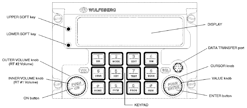
Page 5-4 Publication No. 150-041118
Section 5 – Configuration and Programming Rev. A
Sep 2001
Basic Operation
Front Panel & Controls
DISPLAY - The C-5000 has a 2 line display, with 20 characters on each line. It provides the visual feedback for the
system. Exactly what is displayed depends on the current operating mode of the C-5000. During normal operation,
the top line shows information for transceiver #1 and the bottom line shows information for transceiver #2.
UPPER SOFT key – This key’s use depends on the current operating mode of the C-5000. Some examples of its
use are: increasing the display brightness, and selecting radio 1’s guard receiver.
LOWER SOFT key - This key’s use depends on the current operating mode of the C-5000. Some examples of its
use are: decreasing the display brightness, and selecting radio 2’s guard receiver.
OUTER VOLUME knob – This rotary switch is used to control the volume of radio 2.
INNER VOLUME knob – This rotary switch is used to control the volume of radio 1.
ON button – This button is used to turn the C-5000 on or off.
CURSOR knob – This rotary switch is used to move the cursor around the display.
VALUE knob – This rotary switch is used to modify values above the cursor.
ENTER button – This button’s use is dependent on the C-5000’s current operating mode, but is primarily used to
finalize data entry operations.
DATA TRANSFER PORT – This serial port is used to transfer data between the C-5000 and the Wulfsberg Remote
Programmer software. While preset channels can be programmed from the front panel, the best method is to
use a PC and the Wulfsberg Remote Programming(RP) software.
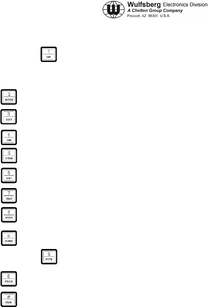
C-5000 COMMUNICATION MANAGEMENT CONTROLLER
INSTALLATION MANUAL
Publication No. 150-041118 Page 5-5
Rev. A Section 5 – Configuration and Programming
Sep 2001
KEYPAD – The C-5000 has a 12 button keypad. Each button’s primary functions are described
below.
1:DIR Toggles the transceiver under cursor control in and out of DIRECT mode. Use this button
to enter a “1” during keypad entry mode.
2:MODE This button will cycle through the enhanced modes of operation. Use this button to
enter a “2” during keypad entry mode.
3:EDIT This button will display the EDIT PAGE for the transceiver under cursor control. Use
this button to enter “3” during keypad entry mode.
4:DIM This button will display the page used to control the display’s brightness. Use this button to enter a “4”
during keypad entry mode.
5:OTAR This button will initiate an “Over The Air Rekey” for the transceiver under cursor control . Use this
button to enter a “5” during keypad entry mode.
6:KEY This button will prompt the user for a transmit encryption key to override the preset value for the transceiver
under cursor control. Use this button to enter a “6” during keypad entry mode.
7:TEST This button will override the squelch system of the radio under cursor control, allowing the user to set the
volume level. Use this button to enter a “7” during keypad entry mode
8:SCAN FUNCTION NOT AVAILABLE AT THIS TIME. Use this button to enter a “8” during keypad entry
mode.
*:HOME This button will display the HOME PAGE, except in some advanced modes of operation, where it will
return the user to a previous page or mode of operation. Use this button to enter a “*” during keypad entry mode.
9:PVTφ
φφ
φ This button will toggle the transceiver under cursor control in and out of private mode.
Use this button to enter a “9” during keypad entry mode.
0:PROG This button will display the programming password page. Use this button to enter a “0”
during keypad entry mode.
#:NUM This button will select keypad entry mode, such as for entering a channel number or
frequency using the keypad. Use this button to enter a “#” during keypad entry mode.
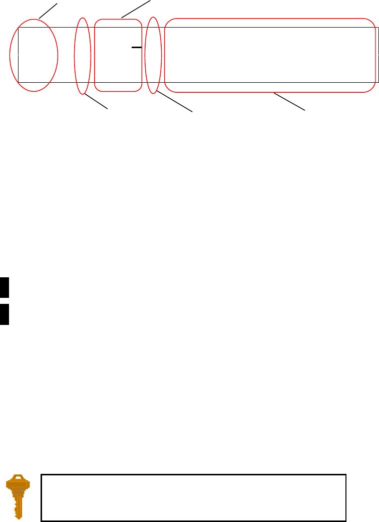
Page 5-6 Publication No. 150-041118
Section 5 – Configuration and Programming Rev. A
Sep 2001
The Home Page
The HOME PAGE is the primary operational page of the C-5000. The HOME PAGE becomes visible when the C-
5000 is ready for user input, immediately after the power up and initialization sequences have completed. The C-
5000 can control two radios. When viewing the HOME PAGE, Radio 1 is always displayed on the top line. Radio
2 is always displayed on the bottom line. Virtually all keypad-initiated operations are performed on the radio under
cursor control. The radio under cursor control in the radio whose line the cursor is currently located on. The cursor
can be quickly toggled between radios (display lines) by pressing the ENTER button.
The following illustration is an example of what the HOME PAGE looks like.
1 123→
→→
→LUKEAFB TWR1
2
φ
φφ
φ
..1 TACTICAL-001
Main/Guard Status Fields – These fields display symbols indicating the current status of all the available
transceivers in the system. The symbols are as follows.
. – Indicates a radio is available, but not enabled.
►– Indicates a radio is transmitting.
1 – Indicates radio 1 is available and enabled.
2 – Indicates radio 2 is available and enabled.
1 – Indicates radio 1 is receiving.
2 – Indicates radio 2 is receiving.
Encryption Status Field – This field displays the encryption indicator symbol (φ
φφ
φ) when encryption is turned on, or
a blank if encryption is turned off.
Channel Selection Field – This field displays the currently selected channel.
Direct Mode Status Field – This field displays the direct mode indicator symbol (→
→→
→) when the current channel is a
direct channel, or the channel has been forced to be a direct channel by pressing the DIR button.
Alphanumeric Identifier Field – This field displays the 12 character name of the currently selected channel, unless
the manual channel is selected, in which case the manual channel’s receive frequency will be displayed.
You can always get back to the HOME PAGE by pressing the HOME
button one or more times.
Main/Guard
Status Field
Encryption
Status Field
Channel Selection Field
Direct Mode
Status Field
Alphanumeric
Identifier Field
C-5000 COMMUNICATION MANAGEMENT CONTROLLER
INSTALLATION MANUAL
Publication No. 150-041118 Page 5-7
Rev. A Section 5 – Configuration and Programming
Sep 2001
Turning the System On and Off
To power the C-5000 ON, press and hold the ON button for approximately one second. Several version number and
copyright pages appear on the display while the unit performs a selFtest and initializes the attached radio systems.
When initialization is complete, the HOME PAGE will appear on the display.
To power the C-5000 OFF, press and hold the ON button for several seconds. The following message flashes on the
display several times:
!!!USE CAUTION !!!
TURNING SYSTEM OFF
Continue to hold the ON button until the message stops flashing and the display turns off.
Setting the Display Brightness
When you first power ON the C-5000, the display is at its maximum brightness. To adjust the brightness level,
ensure you are on the HOME PAGE, then press the DIM button. The display will appear as follows.
←
←←
←
UP CHANGE DISPLAY
←
←←
←
DOWN BRIGHTNESS
Press the UPPER SOFT KEY to brighten the display. Press he LOWER SOFT KEY to dim the display. Press the
HOME button to return to the HOME PAGE.
Setting the Volume Level
When you first power ON the C-5000, the volume level will be reset to the level that was active when the unit was
powered down. You can change the volume level as follows.
Radio 1
• Place the cursor on the top line of the display.
• Tune to a channel with activity on it or press the TEST button. This will unsquelch the radio, allowing you to
hear the current volume level.
• Rotate the INNER VOLUME knob clockwise to increase the volume level, or counterclockwise to decrease the
volume level.
Radio 2
• Place the cursor on the bottom line of the display.

Page 5-8 Publication No. 150-041118
Section 5 – Configuration and Programming Rev. A
Sep 2001
• Tune to a channel with activity on it or press the TEST button. This will unsquelch the radio, allowing you to
hear the current volume level.
• Rotate the OUTER VOLUME knob clockwise to increase the volume level, or counterclockwise to decrease the
volume level.
Selecting a Preset Channel Using the Cursor/Value Knob
When the C-5000 first powers on, the selected channels will be reset to those that were active when the unit was
powered down. To select a different preset channel, do one of the following:
• Move the cursor under the least significant digit of the channel number you want to change. The illustration
below shows a user preparing to change the channel for radio 1.
1 123→
→→
→LUKEAFB TWR1
2
φ
φφ
φ
..1 TACTICAL-001
• Turn the VALUE knob clockwise to select the next available channel with a higher number. Turn the VALUE
knob counterclockwise to select the next available channel with a lower number. Keep turning the VALUE
knob until the desired channel is selected.
You can also increment the channel number by 10’s and 100’s. You do this by placing the cursor under the 10’s or
100’s digit and turning the VALUE knob as described above. The following illustration depicts the cursor under the
10’s digit. The 100’s digit would be one to the left of the 10’s digit.
1 123→
→→
→LUKEAFB TWR1
2
φ
φφ
φ
..1 TACTICAL-001
Selecting a Channel Using the Keypad
Occasionally, it is desirable to select a preset channel by entering its number via the keypad, rather than dialing it in
with the cursor/value knobs. This can be performed as follows.
• Place the cursor under any digit of the channel number you want to change.
• Press the NUM button. The following illustration depicts the display after the NUM button has been pressed
while radio 1 was under cursor control.
C-5000 COMMUNICATION MANAGEMENT CONTROLLER
INSTALLATION MANUAL
Publication No. 150-041118 Page 5-9
Rev. A Section 5 – Configuration and Programming
Sep 2001
1 CHAN=..0 <ENTER>
2φ
φφ
φ..1 TACTICAL-001
• Input the channel number using the keypad buttons.
• Press the ENTER button.
The input channel number will be selected, assuming it was a valid channel. If you input an invalid channel number,
the display will reappear as depicted above, giving you the opportunity to input a valid channel number. You can
press the HOME button to cancel the input operation and return to the HOME PAGE.
Selecting a Channel by Alphanumeric Identifier
It is sometimes desirable to select a preset channel by name as opposed to number. This can be performed as
follows.
• Place the cursor under the alphanumeric identifier field of the radio you want to tune the channel on. The
following illustrating shows the cursor under radio 1’s alphanumeric identifier field.
1 123→
→→
→LUKEAFB TWR1
2φ
φφ
φ..1 TACTICAL-001
• Rotate the VALUE knob clockwise to select the next channel in alphabetic order. Turning the VALUE knob
counterclockwise will select the previous channel in alphabetic order. Continue to turn the VALUE knob until
the desired channel is displayed.
1) The manual channel cannot be selected this way.
2) The cursor will not move under the alphanumeric identifier field if the manual channel is
selected.
Selecting the Manual Channel
The manual channel is used to tune channels not already programmed as presets into the C-5000’s memory. Each
radio has its own manual channel. The manual channel is located at channel number 0, and is displayed as “..M”.
You can select the manual channel by either entering channel 0 from the keypad, or by dialing it in using the
cursor/value knobs. The following illustration depicts a C-5000 with the manual channel for radio 1 selected.
NOTE:
Page 5-10 Publication No. 150-041118
Section 5 – Configuration and Programming Rev. A
Sep 2001
1 ..M 156.200
2φ
φφ
φ..1 TACTICAL-001
The manual channel’s frequency is displayed in place of the alphanumeric identifier for preset channels. Once the
manual channel is selected, press the EDIT button to edit the channel information. The C-5000 automatically stores
the manual channel information on power down.
Using the Direct/Repeat Feature
The C-5000 supports both direct and repeat modes of operation. Any preset channel that has identical transmit and
receive frequencies is considered a direct channel. If the transmit and receive frequencies are different, the C-5000
considers the channel a repeater channel. Repeater channels can be temporarily changed into direct channels by
pressing the DIR button. This will temporarily copy the receive frequency into the transmit frequency. The direct
mode indicator will light. The following illustration shows radio 1 in direct mode.
1 123→
→→
→LUKEAFB TWR1
2φ
φφ
φ..1 TACTICAL-001
Pressing the DIR button on a direct channel has no effect.
Receiving/Transmitting
Receiving
The C-5000 is constantly monitoring its radios for reception. When a signal is received, the C-5000 will light the
receive indicator for the receiving radio, and route the audio to the operator’s headset (Assuming the associated
intercom switch is selected). The following illustration depicts Radio #1 receiving.
1123→
→→
→LUKEAFB TWR1
2φ
φφ
φ..1 TACTICAL-001
Transmitting
To transmit on a radio system, select the appropriate source on your audio panel, and key the microphone.
Transmission will begin on the radio’s currently selected channel. During the transmission, the radio’s transmit
indicator will light, and the channel’s transmit frequency will be displayed. The following illustration depicts radio
1 transmitting.
RX Indicator
Direct Mode Indicator
NOTE:
C-5000 COMMUNICATION MANAGEMENT CONTROLLER
INSTALLATION MANUAL
Publication No. 150-041118 Page 5-11
Rev. A Section 5 – Configuration and Programming
Sep 2001
►
►►
►123→
→→
→300.000T
2φ
φφ
φ..1 TACTICAL-001
Enabling/Disabling Transceivers
Disabling (Turning Off) a Transceiver
• Place the cursor under the R/T status indicator. The following illustration shows the cursor under Radio #1’s
status indicator.
1123→
→→
→LUKEAFB TWR1
2φ
φφ
φ..1 TACTICAL-001
• Rotate the VALUE knob once in either direction. The display will indicate the radio has been turned off, as the
following illustrates.
.RADIO OFF
2φ
φφ
φ..1 TACTICAL-001
Enabling (Turning On) a Transceiver
• Place the cursor under the radio’s status indicator. The following illustration shows the cursor under Radio
#2’s status indicator.
1 123→
→→
→LUKEAFB TWR1
.RADIO OFF
• Rotate the VALUE knob once in either direction. The display will indicate the radio has been turned on, as the
following illustrates.
TX Indicator

Page 5-12 Publication No. 150-041118
Section 5 – Configuration and Programming Rev. A
Sep 2001
1 123→
→→
→LUKEAFB TWR1
2φ
φφ
φ..1 TACTICAL-001
C-5000 COMMUNICATION MANAGEMENT CONTROLLER
INSTALLATION MANUAL
Publication No. 150-041118 Page 5-13
Rev. A Section 5 – Configuration and Programming
Sep 2001
Using The Edit Page
The EDIT PAGE allows the operator to temporarily change properties of a preset channel, and permanently change
properties of a manual channel. Precisely which properties can be changed varies with channel and radio type. For
example, transmit power can only be changed on RT-5000 radios, because the other radios do not have variable
power capability. The following illustration is an example of what the EDIT PAGE looks like. Your C-5000’s
display may appear differently depending on the currently selected channel and its associated properties.
..1→
→→
→506.987R T.17 FM
S H 506.987T T.17 ..
Channel Identifier field – This displays the currently selected channel, i.e. the channel you are editing.
Direct Mode Status Field – This field displays the direct mode indicator symbol (→) when the current channel is a
direct channel, or the channel has been forced to be a direct channel by way of the DIR button.
Receive Frequency Field – This field displays the current channel’s receive frequency.
Receive Tone Field – This field displays the current channel’s receive tone.
Modulation Type Field – This field displays the current channel’s modulation type. The modulation types are
displayed as AM, FM, P (P25), and TK (trunking).
Channel Bandwidth Field – This field displays the current channel’s bandwidth. Bandwidths are displayed as S
(standard), W (wide), X (extra wide), and N (narrow).
Transmit Power Level Field – This field displays the current channel’s transmit power level. Power level is
displayed as HI for high power or LO for low power.
Transmit Frequency Field – This field displays the current channel’s transmit frequency.
Transmit Tone Field – This field displays the current channel’s transmit tone.
Encryption Key Field – This field displays the current channel’s transmit encryption key. The encryption key will
display as a number between 1 and 16, or “..” if no key has been specified for the channel.
Editing a Preset Channel
To temporarily change the properties of a preset channel, do the following.
Bandwidth
Power Level Transmit
Frequency
Transmit
Tone
Encryption
Key
Direct Mode
Indicator
Channel Receive
Frequency Receive
Tone
Modulation

Page 5-14 Publication No. 150-041118
Section 5 – Configuration and Programming Rev. A
Sep 2001
• On the HOME PAGE, select the preset channel you want to edit.
• Press the EDIT button to load the channel into the EDIT PAGE.
• Move the cursor under the field containing the channel property you want to edit.
• Use the VALUE knob to change the property to the desired value.
• Press the HOME button to return to the HOME PAGE. The changes will remain in effect until the channel is
changed.
The cursor cannot be moved under channel property fields that are not editable.
Editing a Manual Channel
To change the properties of a manual channel, do the following.
• On the HOME PAGE, select the manual channel you want to edit.
• Press the EDIT button to display the EDIT PAGE.
• Move the cursor under the field containing the channel property you want to edit.
• Use the VALUE knob to change the property to the desired value.
• Press the HOME button to return to the HOME PAGE and save the manual channel’s current state.
The cursor cannot be moved under channel property fields that are not editable.
Changing PL & DPL (CTCSS and DCS) Tones
The C-5000 supports both CTCSS (PL) and DCS (DPL) tones. The tone used by a channel can be temporarily
overridden on the EDIT PAGE. You can select any valid tone, or turn tones off. (Channels programmed to use the
ITM of a Guard receiver module in a RT-5000 cannot be changed)
Turning Tones Off
• Move the cursor under the “T” of the receive tone field, as depicted below.
..1 506.987R T.17 FM
S H 509.987T T.17 ..
• Rotate the VALUE knob clockwise once. The receive tone field will show “…” as depicted below.
NOTE:
NOTE:
C-5000 COMMUNICATION MANAGEMENT CONTROLLER
INSTALLATION MANUAL
Publication No. 150-041118 Page 5-15
Rev. A Section 5 – Configuration and Programming
Sep 2001
..1 506.987R T... FM
S H 509.987T T.17 ..
• Press the ENTER button to move the cursor under the “T” of the transmit tone field.
• Rotate the VALUE knob clockwise once. The transmit tone field will show “…” as depicted below.
..1 506.987R T... FM
S H 509.987T T... ..
Selecting a CTCSS Tone
• Move the cursor under the least significant digit of the tone field you want to change. The illustration below
assumes we want to change the receive tone.
..1 506.987R T.17 FM
S H 509.987T T.17 ..
• Rotate the VALUE knob clockwise to increment the tone, or counterclockwise to decrement the tone. Keep
rotating the VALUE knob until the desired tone is displayed.
Appendix A lists the frequencies associated with the Wulfsberg CTCSS tone numbers.
Selecting a DCS Tone
• Move the cursor under the most significant digit of the tone field you want to change. The illustration below
assumes we want to change the receive tone.
NOTE:
Page 5-16 Publication No. 150-041118
Section 5 – Configuration and Programming Rev. A
Sep 2001
..1 506.987R T.17 FM
S H 509.987T T.17 ..
• Rotate the VALUE knob clockwise to increment the tone, or counterclockwise to decrement the tone. Continue
rotating the VALUE knob until the most significant digit is that of the desired tone.
• Move the cursor under the least significant digit of the tone, as illustrated below.
..1 506.987R T023 FM
S H 509.987T T.17 ..
• Rotate the VALUE knob clockwise to increment the tone, or counterclockwise to decrement the tone. Keep
rotating the VALUE knob until the desired tone is displayed.
Changing Transmit Power
The C-5000 supports the selection of high and low transmit power. Normally high power is used, however, if
interference or other transmit issues are experienced, low power may be selected to help remedy the issue. If you
have a radio that supports multiple power levels, such as the RT-5000, you can alter the power setting from the
EDIT PAGE as follows.
• Move the cursor under the transmit power field, as depicted below.
..1 506.987R T.17 FM
SH509.987T T.17 ..
• Rotate the VALUE knob clockwise once. The power indicator will toggle between high and low with each turn
of the VALUE knob.
Changing Modulation Type
The modulation type can be only be changed on the manual channel, and can only toggle between AM and FM. To
change the manual channel’s modulation type, do the following.
• Move the cursor under the modulation field, as depicted below.
A “0-7” in the first position means you are selecting a DCS
tone. This is a special kind of tone rarely used.
C-5000 COMMUNICATION MANAGEMENT CONTROLLER
INSTALLATION MANUAL
Publication No. 150-041118 Page 5-17
Rev. A Section 5 – Configuration and Programming
Sep 2001
..1 506.987R T.17 FM
S H 509.987T T.17 ..
• Rotate the VALUE knob clockwise once. The modulation indicator will toggle between AM and FM. (118-
136 MHz and 225-400 MHz are normally AM frequencies. All other frequencies are usually FM)
Changing Receiver Bandwidth
The receiver bandwidth can only be changed on the manual channel. To change the manual channel’s receiver
bandwidth, do the following.
• Move the cursor under the bandwidth field, as depicted below.
..1 506.987R T.17 FM
SH 509.987T T.17 ..
• Rotate the VALUE knob in either direction. Each turn of the VALUE knob will select the next bandwidth
option in the list. Turn the VALUE knob until the desired bandwidth symbol is displayed. The available
options are as follows.
N – Narrow – 12.5 kHz
S – Standard - 25 kHz
W – Wide – 35 kHz
X – Extra Wide – 70 kHz
UNLESS SPECIFICALLY INSTRUCTED OTHERWISE, ALWAYS SELECT “S”.

Page 5-18 Publication No. 150-041118
Section 5 – Configuration and Programming Rev. A
Sep 2001
Enhanced System Features
Phone Patch Mode
The C-5000 can patch into the phone system using both DTMF and pulse dialing. This requires equipment on the
ground, such as a transceiver and an interface box, to connect the base station radio to the telephone lines. This is
NOT a cellular phone.
• From the HOME PAGE, select the radio and channel. Press the MENU button. The following display page
will appear.
←
←←
←
DTMF SELECT PHONE
←
←←
←
PULSE DIALING MODE
• Press the UPPER SOFT KEY to select DTMF dialing, or the LOWER SOFT KEY to select pulse dialing. In
either case, the next display page will appear, and will look similar to the following. This example shows the
dialing operation being performed on radio 1, channel 1.
←
←←
←
SEND 1 ..1
←
←←
←
HOME #-_
• Input the digits you want to dial using the keypad. Alpha characters can be input by turning the VALUE knob
until the desired character is displayed, then pressing the ENTER button. Pressing the ENTER button while a
blank is displayed inputs a ½ second delay. As soon as you begin input, the display will change slightly. The
following depicts a sample entry.
←
←←
←
SEND 1 ..1
←
←←
←
CLR #-12345678*90#
• Press the UPPER SOFT KEY to dial the displayed data, or the LOWER SOFT KEY to erase the displayed data.
• Press the HOME button (LOWER SOFT BUTTON !!!!!!) to return to the HOME PAGE.
Simulcast Operation
Simulcast Mode allows you to transmit simultaneously to two other locations that have radios tuned to different
frequencies. At the same time, the Main RT systems and Guard Receivers are able to receive on their currently
selected channels. You can establish simulcast operation as follows.
C-5000 COMMUNICATION MANAGEMENT CONTROLLER
INSTALLATION MANUAL
Publication No. 150-041118 Page 5-19
Rev. A Section 5 – Configuration and Programming
Sep 2001
• Ensure you are on the HOME PAGE.
• Select the desired channel for radio 1.
• Select the desired channel for radio 2.
• Press the MODE button until the following display page appears.
PRESS ENTER BUTTON
FOR SIMULCAST MODE
• Press the ENTER button. The following illustrates the SIMULCAST PAGE for radio 1 on channel 1 and radio
2 on channel 2.
SIMULCAST MODE
1 ..1 2 ..2
• Press the HOME button to exit simulcast mode and return to the HOME PAGE.
• Use either RT1 or RT2 mic position on the audio selector panel and initiate a transmission. Both Radios will
transmit at the same time.
Relay Operation
Relay Mode allows your aircraft’s C-5000-based transceiver system to function as a cross-band repeater. If a Relay
Mode link is established between two locations, a message received from one location is automatically retransmitted
to the other. You can establish relay operation as follows.
• Ensure you are on the HOME PAGE.
• Select the desired channel for radio 1.
• Select the desired channel for radio 2.
• Press the MODE button until the following display page appears.

Page 5-20 Publication No. 150-041118
Section 5 – Configuration and Programming Rev. A
Sep 2001
PRESS ENTER BUTTON
FOR RELAY MODE
• Press the ENTER button. The following illustrates the RELAY PAGE for radio 1 on channel 1 and radio 2 on
channel 2.
RELAY MODE
1 ..1 2 ..2
• Press the HOME button to exit relay mode and return to the HOME PAGE.
Relay/Simulcast Operation
Relay-Simulcast mode combines the functions of Relay Mode and Simulcast Mode. It allows you to establish an
automatic radio link with two other locations that have radios tuned to different frequencies in different frequency
bands, and allows you to transmit to those same locations simultaneously. You can establish relay/simulcast
operation as follows.
• Ensure you are on the HOME PAGE.
• Select the desired channel for radio 1.
• Select the desired channel for radio 2.
• Press the MODE button until the following display page appears.
PRESS ENTER BUTTON
FOR RELAY/SIMULCAST
• Press the ENTER button. The following illustrates the RELAY/SIMULCAST PAGE for radio 1 on channel 1
and radio 2 on channel 2.
RELAY/SIMULCAST MODE
1 ..1 2 ..2
• Press the HOME button to exit relay/simulcast mode and return to the HOME PAGE.
C-5000 COMMUNICATION MANAGEMENT CONTROLLER
INSTALLATION MANUAL
Publication No. 150-041118 Page 5-21
Rev. A Section 5 – Configuration and Programming
Sep 2001
Repeater Operation
Repeater mode allows the C-5000-based system to act as an airborne repeater, providing a radio link between two
ground locations that transmit and receive in the same frequency band. You can establish repeater operation as
follows.
• Ensure you are on the HOME PAGE.
• Select the desired channel for radio 1.
• Press the MODE button until the following display page appears.
PRESS ENTER BUTTON
FOR REPEATER MODE
• Press the ENTER button. The following illustrates the REPEATER PAGE for radio 1 on channel 1 and radio 2
on channel 2.
REPEATER MODE
1 ..1 2 RCV
• Press the HOME button to exit repeater mode and return to the HOME PAGE.
NOTE: Repeater operation on channels that use the Guard module in the transceiver must
cannot accomplished using this method. Any P25 or Encryption capable channels cannot
be setup in repeater mode unless special channels are programmed. The following
procedure should be followed under this condition:
1) Select the repeater channel on RT #1.
2) Press DIR button to put RT #1 into direct mode.
3) Select the repeater channel alternate on RT #2.
4) Enter into repeater mode using the procedure above.
Page 5-22 Publication No. 150-041118
Section 5 – Configuration and Programming Rev. A
Sep 2001
Encryption Features
Turning Encryption On and Off
Put the cursor on the top or bottom line depending on which radio is to be selected. Press the PVT button to toggle
encryption on and off. If the C-5000 has been configured to control an RT-5000 with an encryption module and the
preset channel being used has been set up for encryption, the privacy indicator will light.
Encryption can only be turned on for channels that have been pre-programmed with an encryption
key. Three error beeps will sound if the channel has not been setup for encryption.
Changing the channel will automatically reset the encryption setting to OFF. The
encryption device in the RT-5000 will still decode encrypted messages i.e. the encryption
ON/OFF affects only the transmit and not the receive function of the encryption unit.
Selecting an Encryption Key
The preset encryption key (sometimes called KEYMAT) for a channel can be temporarily changed as follows.
• Ensure you are on the HOME PAGE, and the cursor is on the line of the radio you wish to select and encryption
capable channel is also selected.
• Press the KEY button. The following illustrates the display when the KEY button was pressed with the cursor
on the top line, i.e. on radio 1. If the KEY button is pressed on a channel that has not been preset to use
encryption, three warning beeps will sound.
TX KEY=PSET<ENTER>
2
φ
φφ
φ
..1 TACTICAL-001
• Rotate the VALUE knob to change the encryption key. A value of “PSET” indicates you want to use the
channel’s preset encryption key. A numeric value (1-16) indicates you want to override the preset key with the
specified key.
• Press the ENTER button to accept the displayed key. The display will return to the HOME PAGE.
• When transmitting, a if encryption keys are properly loaded, a tone at the start of the transmission will be
generated by the radio and heard by the operator. Begin speaking AFTER the tone or part of your transmission
will be lost.
• When transmitting in the encrypted mode, if you hear a continuous warble tone, this indicates that the
encryption key(s) have not been loaded. Either manually enter encryption keys or perform an OTAR if your
system has that capability.
• The newly selected KEYMAT WILL REMAIN even if the channel is changed in effect until power down.
NOTE:
C-5000 COMMUNICATION MANAGEMENT CONTROLLER
INSTALLATION MANUAL
Publication No. 150-041118 Page 5-23
Rev. A Section 5 – Configuration and Programming
Sep 2001
Performing an OTAR
• Ensure you are on the HOME PAGE, and the cursor is on the line of the radio you wish to select and an OTAR
capable channel is also selected.
• Press the OTAR button. The following illustrates the display when the OTAR button was pressed with radio 1
under cursor control.
1 ENTER=START OTAR
2
φ
φφ
φ
..1 TACTICAL-001
• Press the ENTER button to initiate the OTAR process. The status of the OTAR will be displayed on the radio’s
display line. Status messages include “OTAR REQUESTED”, “OTAR IN PROGRESS”, “OTAR
ABORTING”, “OTAR COMPLETE”, and “OTAR FAILED”. The following illustrates the display with an
OTAR in progress.
1 OTAR IN PROGRESS
2φ
φφ
φ..1 TACTICAL-001
• When the OTAR is finished, the display will indicate its success or failure. The following illustrates the display
after a successful OTAR.
1 OTAR COMPLETE
2φ
φφ
φ..1 TACTICAL-001
• Press the HOME button to acknowledge the completion of the OTAR and return to normal HOME PAGE
operation.
• Normal OTAR operations take 10 – 30 seconds depending on signal strength and channel availability.
The OTAR process can be aborted by pressing the HOME button while the “OTAR IN PROGRESS” message is
being displayed. Doing so will send the abort command to the digital transceiver, and display a status message like
the following.
Page 5-24 Publication No. 150-041118
Section 5 – Configuration and Programming Rev. A
Sep 2001
1 OTAR ABORTING
2φ
φφ
φ..1 TACTICAL-001
The OTAR process will automatically time-out after 2 minutes of unsuccessful OTAR attempts.
Erasing Encryption Keys
It may be desirable to erase the encryption keys contained in a RT-5000 transceiver. For example, prior to sending
the unit in for service. This can be accomplished as follows.
• Ensure you are on the HOME PAGE, and the cursor is on an encryption capable channel.
• Press the PROG button. You will be prompted to enter a password, as follows.
ENTER PASSWORD 2
#=.... <ENTER>
• Input the appropriate password using the keypad and press the ENTER button.
• Press the MODE button until the following display page appears.
PROG: 2=NEXT 3=BACK
<ENTER>= KEY ERASE
• Press the ENTER button to invoke the KEY ERASE PAGE, depicted below.
←
←←
←
START KEY ERASE
RADIO=1 ITM=VHF138
• Use the cursor/value knobs to select the radio and digital receiver module you want to erase the encryption keys
from. Press the UPPER SOFT KEY to initiate the erase process. The display will appear similar to the
following.
NOTE:
C-5000 COMMUNICATION MANAGEMENT CONTROLLER
INSTALLATION MANUAL
Publication No. 150-041118 Page 5-25
Rev. A Section 5 – Configuration and Programming
Sep 2001
←
←←
←
END KEY ERASE
RADIO #1 KEYS ERASED
• Press the UPPER SOFT KEY to acknowledge the key erase is complete. The display will return to the main
KEY ERASE PAGE, allowing you to select another radio and/or digital transceiver module to erase.
• When finished erasing the keys from all desired modules, press the HOME button to return to the HOME
PAGE.
Manually Loading Encryption Keys
It may be desirable to manually load the encryption keys contained in a RT-5000 digital transceiver. This can be
accomplished as follows.
• Ensure you are on the HOME PAGE, and the cursor is on an encryption capable channel.
• Press the PROG button. You will be prompted to enter a password, as follows.
ENTER PASSWORD 2
#=.... <ENTER>
• Input the appropriate password using the keypad and press the ENTER button.
• Press the MODE button until the following display page appears.
PROG: 2=NEXT 3=BACK
<ENTER>= KVL LOAD
• Press the ENTER button to invoke the KVL LOAD PAGE, depicted below.
←
←←
←
START KVL LOAD
RADIO=1 ITM=VHF138
• Use the cursor/value knobs to select the radio and desired Internal Transceiver Module (ITM) you want to load
the encryption keys . The RT-5000 can have up to two modules covering two frequency bands per unit. Only
available options will be displayed. Once the desired radio and ITM have been selected, press the UPPER
SOFT KEY to initiate the load process. The display will appear similar to the following.

Page 5-26 Publication No. 150-041118
Section 5 – Configuration and Programming Rev. A
Sep 2001
←
←←
←
END KVL LOAD
RADIO #1 IN KVL MODE
• Connect the Key-loader device to the transceiver data port. Load the desired keys using the procedure for the
key-loader as prescribed its manufacturer.
• Press the UPPER SOFT KEY to acknowledge the key load is complete. The display will return to the main
KVL LOAD PAGE, allowing you to select another radio and/or digital transceiver module to load.
• When finished loading the keys to all desired modules, press the HOME button to return to the HOME PAGE.
C-5000 COMMUNICATION MANAGEMENT CONTROLLER
INSTALLATION MANUAL
Publication No. 150-041118 Page 5-27
Rev. A Section 5 – Configuration and Programming
Sep 2001
Programming Preset Channels
WARNING: CONFIGURING THE C-5000 MUST BE PERFORMED BEFORE PRESET CHANNELS
ARE PROGRAMMED FOR THE UNIT TO OPERATE PROPERLY !!!!
Programming Preset Channels Using the Front Panel
Although Wulfsberg highly recommends using the PC based Remote Programmer software to program preset
channels for the C-5000, they can be programmed from the front panel. The process is as follows.
• Ensure you are on the HOME PAGE.
• Press the PROG button. If the C-5000 has been programmed to require a password to enter this mode, you will
be prompted to enter a password, as follows.
ENTER PASSWORD 2
#=.... <ENTER>
• Input the appropriate password using the keypad and press the ENTER button.
• Press the MODE button until the following display page appears.
PROG: 2=NEXT 3=BACK
<ENTER>= CHANNELS
• Press the ENTER button to invoke the CHANNEL MAIN MENU PAGE, depicted below.
PROG: CHANNEL
2=ADD 3=CHG 4=DEL
• Press the MODE button to add a new channel or the EDIT button to modify an existing channel. The pages are
nearly identical for both functions. The illustrations that follow assume we are adding a channel, i.e. we pressed
the MODE button.
Page 5-28 Publication No. 150-041118
Section 5 – Configuration and Programming Rev. A
Sep 2001
PROG: 2=NEXT 3=BACK
ADD-..1
• Use the cursor/value knobs to select the number for the new channel. Only available channel numbers will be
displayed. Press the MODE button to go to the next menu page.
PROG: 2=NEXT 3=BACK
R/TSYS#=1
• Use the cursor/value knobs to select the radio this channel is being programmed for. Press the MODE button to
go to the next menu page.
• If both radios are RT-5000’s with the same part number, both radios will be able to use any channel. In this
case, set this value to “1”.
PROG: 2=NEXT 3=BACK
CHAN ID=............
• Use the cursor/value knobs to input the alphanumeric identifier for the channel being programmed. This
identifier can be a maximum of 12 characters in length. Turning the VALUE knob will enumerate all the
characters available for the identifier. Press the MODE button to go to the next menu page.
PROG: 2=NEXT 3=BACK
CHANNEL TYPE= FM
• Use the cursor/value knobs to input the modulation type for the channel being programmed. This can be AM,
FM, P (P25), or TK (trunking). Press the MODE button to go to the next menu page.
PROG: 2=NEXT 3=BACK
ZONE= .. CHANNEL= ..
• Use the cursor/value knobs to input the zone and channel number for a RT-5000 digital transceiver channel.
Leave these fields blank if you are not programming a digital transceiver channel. Press the MODE button to
go to the next menu page.
C-5000 COMMUNICATION MANAGEMENT CONTROLLER
INSTALLATION MANUAL
Publication No. 150-041118 Page 5-29
Rev. A Section 5 – Configuration and Programming
Sep 2001
• IF THE CHANNEL IS TO BE PROGRAMMED FOR THE INTERNAL TRANSCEIVER MODULE IN
THE RT-5000, THE ZONE AND CHANNEL MUST MATCH THE ZONE, CHANNEL, AND
FREQUENCY INFORMATION PROGRAMMED INTO THE ITM.
PROG: 2=NEXT 3=BACK
RX FREQ=000.000
• Use the cursor/value knobs or the keypad to input the channel’s receive frequency. Press the MODE button to
go to the next menu page.
PROG: 2=NEXT 3=BACK
RX TONE=...
• Use the cursor/value knobs to input the channel’s receive tone. Refer to the section on changing tones via the
EDIT PAGE for details on specifying DCS and CTCSS tones. Press the MODE button to go to the next menu
page.
PROG: 2=NEXT 3=BACK
TX FREQ=000.000
• Use the cursor/value knobs or the keypad to input the channel’s transmit frequency. Specifiying a transmit
frequency of 000.000 indicates the channel is a receive-only channel. Press the MODE button to go to the next
menu page.
PROG: 2=NEXT 3=BACK
TX TONE=...
• Use the cursor/value knobs to input the channel’s transmit tone. Refer to the section on changing tones via the
EDIT PAGE for details on specifying DCS and CTCSS tones. Press the MODE button to go to the next menu
page.
PROG: 2=NEXT 3=BACK
TX POWER= HI
• Use the cursor/value knobs to input the channel’s transmit power as HI or LO. Press the MODE button to go to
the next menu page.
Page 5-30 Publication No. 150-041118
Section 5 – Configuration and Programming Rev. A
Sep 2001
PROG: 2=NEXT 3=BACK
ENCRYPTION TYPE=CLR
• Use the cursor/value knobs to input the channel’s encryption type. This option can be CLR (no encryption),
EXT (external encryption), STD (internal encryption on internal transceiver module), or OTAR (internal
encryption with OTAR capability on internal transceiver module). Press the MODE button to go to the next
menu page.
PROG: 2=NEXT 3=BACK
ENCRYPTION KEY= ..
• Use the cursor/value knobs to input the channel’s encryption key. This page will only appear if applicable, i.e.
an encryption type of STD or OTAR was specified above. Press the MODE button to go to the next menu page.
PROG: 2=NEXT 3=BACK
RX BANDWIDTH= STD
• Use the cursor/value knobs to input the channel’s receive bandwidth. Valid options are STD (standard),
NARROW, WIDE, and X-WIDE (extra wide). Press the MODE button to go to the next menu page. Normal
setting is STD.
PROG: 2=NEXT 3=BACK
4=ADVANCED FEATURES
• Typically, the previous channel properties are all you need to specify. Pressing the MODE button will skip over
the “advanced features” menu pages to the page that lets you permanently save your channel.
• Channels using an ITM in the RT-5000 will NEVER require the user to input advanced information.
• Press the DIM button to continue with the “advanced features”.
PROG: 2=NEXT 3=BACK
2ND IF INJECTION= HI
• Use the cursor/value knobs to input the channel’s second I.F. Injection as HI or LO. The default is HI. Press
the MODE button to go to the next menu page.
C-5000 COMMUNICATION MANAGEMENT CONTROLLER
INSTALLATION MANUAL
Publication No. 150-041118 Page 5-31
Rev. A Section 5 – Configuration and Programming
Sep 2001
PROG: 2=NEXT 3=BACK
3RD IF INJECTION= HI
• Use the cursor/value knobs to input the channel’s third I.F. Injection as HI or LO. The default is LO. Press the
MODE button to go to the next menu page.
PROG: 2=NEXT 3=BACK
RX AUDIO PHASE= 0
• Use the cursor/value knobs to input the channel’s receive audio phase as 0 or 180. The default is 0. Press the
MODE button to go to the next menu page.
PROG: 2=NEXT 3=BACK
TX AUDIO PHASE= 0
• Use the cursor/value knobs to input the channel’s transmit audio phase as 0 or 180. The default is 0. Press the
MODE button to go to the next menu page.
PROG: 2=NEXT 3=BACK
TX DEVIATION= 5.0KHZ
• Use the cursor/value knobs to input the channel’s transmit deviation. This can be 3.0KHz, 5.0KHz, 4.0KHz, or
5.6KHz. The default is 5.0KHz. Press the MODE button to go to the next menu page.
PROG: 2=SAVE 3=BACK
..1 PRESET CHAN1
• Press the MODE button to permanently save the channel and return to the CHANNEL MAIN MENU PAGE.
You may also review your changes by pressing the EDIT button, or cancel the operation by pressing the HOME
button.

Page 5-32 Publication No. 150-041118
Section 5 – Configuration and Programming Rev. A
Sep 2001
Configuring the C-5000
Configuring the C-5000
Although Wulfsberg highly recommends using the PC based Remote Programmer software to specify the C-5000’s
configuration, it can be specified from the front panel. The process is as follows.
• Ensure you are on the HOME PAGE.
• Press the PROG button. You will be prompted to enter a password, as follows.
ENTER PASSWORD 2
#=.... <ENTER>
• Input the appropriate password using the keypad and press the ENTER button.
• Press the MODE button until the following display page appears.
PROG: 2=NEXT 3=BACK
<ENTER>= CFG SYSTEM
• Press the ENTER button. You will be prompted to enter a password, as follows.
ENTER PASSWORD 1
#=.... <ENTER>
• Input the appropriate password and press the ENTER button. The display will appear as follows.
SETUP: 2=NEXT 3=BACK
C5000 P/N = 1220
• Use the cursor/value knobs to input the last four digits of your C-5000’s part number. Press the MODE button
to display the next menu page.
C-5000 COMMUNICATION MANAGEMENT CONTROLLER
INSTALLATION MANUAL
Publication No. 150-041118 Page 5-33
Rev. A Section 5 – Configuration and Programming
Sep 2001
SETUP: 2=NEXT 3=BACK
ENTER=SETUP RADIO #1
• You can press the ENTER button to configure radio 1. Refer to the sections on configuring RT-5000 and non-
RT-5000 radios for details on these sub-menu pages. Press the MODE button to display the next menu page.
SETUP: 2=NEXT 3=BACK
ENTER=SETUP RADIO #2
• You can press the ENTER button to configure radio 2. Refer to the sections on configuring RT-5000 and non-
RT-5000 radios for details on these sub-menu pages. Press the MODE button to display the next menu page.
SETUP: 2=NEXT 3=BACK
ENTER=CHG PASSWORD 1
• You can press the ENTER button to change the system configuration password. Refer to the section on
changing passwords for details on these sub-menu pages. Press the MODE button to display the next menu
page.
SETUP: 2=NEXT 3=BACK
ENTER=CHG PASSWORD 2
• You can press the ENTER button to change the programming password. Refer to the section on changing
passwords for details on these sub-menu pages. Press the MODE button to display the next menu page.
SETUP: 2=NEXT 3=BACK
ENTER=SETUP MISC.
• You can press the ENTER button to change miscellaneous system properties, such as system encryption, side-
tones, and de-emphasis. Refer to the section on miscellaneous configuration options for details on these sub-
menu pages. Press the MODE button to display the next menu page.
Page 5-34 Publication No. 150-041118
Section 5 – Configuration and Programming Rev. A
Sep 2001
SYSTEM SETUP MODE
HOME=EXIT 2=REVIEW
• Press the HOME button to exit system configuration, or the MODE button to review current settings.
Configuring the C-5000 to Control an RT-5000
This section drills down into the radio setup sub-menu pages. Refer to the section on configuring the C-5000 for
details on how to reach these menu pages. This section assumes the C-5000 part number you entered indicated an
RT-5000 was present for Radio #1. We pick up at the following display page.
SETUP: 2=NEXT 3=BACK
ENTER=SETUP RADIO #1
• Press the ENTER button to begin configuring the RT-5000.
SYS #1:2=NEXT 3=BACK
RT-5000 P/N = 0703
• Use the cursor/value knobs to input the last four digits of your RT-5000’s part number. Press the MODE button
to display the next menu page.
SYS #1:2=NEXT 3=BACK
ENTER=SETUP GUARD #1
• This page will only display if RT-5000 part number entered indicates a Guard receiver is present. Pressing the
ENTER button invokes the preset channel programming menu pages for the Guard channel. Refer to the
section on programming a preset channel for details since programming a Guard channel is very similar to
programming a preset channel.
SYS #1:2=NEXT 3=BACK
RADIO MODE = 1
• This page will only display if RT-5000 part number entered indicates an ITM is present. Use the cursor/value
knobs to select a value of 1 or 2. Mode 1 indicates that the ITM should act as part of the main transceiver, i.e.
the two transceivers appear to be a single unit. Mode 2 indicates that the ITM should not act as part of the
main, i.e. behave as a Guard receiver. . Press the MODE button to display the next menu page.
C-5000 COMMUNICATION MANAGEMENT CONTROLLER
INSTALLATION MANUAL
Publication No. 150-041118 Page 5-35
Rev. A Section 5 – Configuration and Programming
Sep 2001
←
←←
←
INC 2=NEXT 3=BACK
←
←←
←
DEC SQUELCH LVL=160
• This page allows you to set the RT-5000’s squelch level. Press the UPPER SOFT KEY to increase the squelch
level, or the LOWER SOFT KEY to decrease squelch level. The squelch level determines the signal strength
required by the RT-5000 to open its audio gates, allowing you to hear what it is receiving. The larger the
number, the stronger the required signal. Press the MODE button to display the next menu page.
SETUP RADIO #1
HOME=EXIT 2=REVIEW
• Press the HOME button to exit the radio setup menu pages, or press the MODE button to review the current
settings.
Configuring the C-5000 to Control A Non RT-5000
This section drills down into the radio setup sub-menu pages. Refer to the section on configuring the C-5000 for
details on how to reach these menu pages. This section assumes the C-5000 part number you entered indicated a
Flitecomm or Flexcomm I radio was present on radio #2. We pick up at the following display page.
SETUP: 2=NEXT 3=BACK
ENTER=SETUP RADIO #2
• Press the ENTER button to begin configuring the radio.
SYS #2:2=NEXT 3=BACK
RT-30 PRESENT-NO
• Use the cursor/value knobs to tell the C-5000 if an RT-30 is present. Press the MODE button to display the
next menu page.
Page 5-36 Publication No. 150-041118
Section 5 – Configuration and Programming Rev. A
Sep 2001
SYS #2:2=NEXT 3=BACK
RT-118 PRESENT-NO
• Use the cursor/value knobs to tell the C-5000 if an RT-118 is present. Press the MODE button to display the
next menu page.
SYS #2:2=NEXT 3=BACK
RT-138 PRESENT-YES
• Use the cursor/value knobs to tell the C-5000 if an RT-138 is present. Press the MODE button to display the
next menu page.
SYS #2:2=NEXT 3=BACK
RT-138F PRESENT-NO
• Use the cursor/value knobs to tell the C-5000 if an RT-138F is present. Press the MODE button to display the
next menu page.
SYS #2:2=NEXT 3=BACK
RT-450 PRESENT-NO
• Use the cursor/value knobs to tell the C-5000 if an RT-450 is present. Press the MODE button to display the
next menu page.
SYS #2:2=NEXT 3=BACK
RT-406F PRESENT-NO
• Use the cursor/value knobs to tell the C-5000 if an RT-406F is present. Press the MODE button to display the
next menu page.
SYS #2:2=NEXT 3=BACK
RT-9600F PRESENT-NO
• Use the cursor/value knobs to tell the C-5000 if an RT-9600F is present. Press the MODE button to display the
next menu page.
C-5000 COMMUNICATION MANAGEMENT CONTROLLER
INSTALLATION MANUAL
Publication No. 150-041118 Page 5-37
Rev. A Section 5 – Configuration and Programming
Sep 2001
SYS #2:2=NEXT 3=BACK
RT-9600 PRESENT-NO
• Use the cursor/value knobs to tell the C-5000 if an RT-9600 is present. Press the MODE button to display the
next menu page.
SYS #2:2=NEXT 3=BACK
RT-7200 PRESENT-NO
• Use the cursor/value knobs to tell the C-5000 if an RT-7200 is present. Press the MODE button to display the
next menu page.
SYS #2:2=NEXT 3=BACK
GUARD #1 PRESENT-YES
• Use the cursor/value knobs to tell the C-5000 if a Guard is present. Press the MODE button to display the next
menu page.
SYS #2:2=NEXT 3=BACK
ENTER=SETUP GUARD #1
• This page only appears if a guard is present. Press the ENTER button to configure the first Guard channel.
Refer to the preset channel programming section for details on the menu pages that appear. Press the MODE
button to display the next menu page.
SYS #2:2=NEXT 3=BACK
GUARD #2 PRESENT-YES
• This page only appears if a second Guard is possible. Use the cursor/value knobs to tell the C-5000 if a second
Guard is present. Press the MODE button to display the next menu page.
Page 5-38 Publication No. 150-041118
Section 5 – Configuration and Programming Rev. A
Sep 2001
SYS #2:2=NEXT 3=BACK
ENTER=SETUP GUARD #2
• This page only appears if a second guard is present. Press the ENTER button to configure the second Guard
channel. Refer to the preset channel programming section for details on the menu pages that appear. Press the
MODE button to display the next menu page.
SYS #2:2=NEXT 3=BACK
TONE BOARD CTCSS-NO
• Use the cursor/value knobs to tell the C-5000 if a CTCSS tone board is present. Press the MODE button to
display the next menu page.
SYS #2:2=NEXT 3=BACK
TONE BOARD DCS-NO
• Use the cursor/value knobs to tell the C-5000 if a DCS tone board is present. Press the MODE button to display
the next menu page.
SETUP RADIO #2
HOME=EXIT 2=REVIEW
• Press the HOME button to exit the radio setup menu pages, or press the MODE button to review the current
settings.
Setting Passwords
This section drills down into the password setup sub-menu pages. Refer to the section on configuring the C-5000
for details on how to reach these menu pages. This section assumes we want to change password 1. The process is
the same for password 2. We pick up at the following display page.
SETUP: 2=NEXT 3=BACK
ENTER=CHG PASSWORD 1
• Press the ENTER button to begin the password changing process. The display will appear as follows.
C-5000 COMMUNICATION MANAGEMENT CONTROLLER
INSTALLATION MANUAL
Publication No. 150-041118 Page 5-39
Rev. A Section 5 – Configuration and Programming
Sep 2001
ENTER NEW PASSWORD 1
#=.... <ENTER>
• Use the keypad to input the new password, and press the ENTER button.
←
←←
←
BACK VERIFY INPUT
#=.... <ENTER>
• Use the keypad to re-input the new password, and press the ENTER button. This second entry is for
verification. If you entered an inconsistent password, your input will be erased, and you may try again. Once
you have entered the same password on both pages, it will be changed, and the display will revert to the
following.
SETUP: 2=NEXT 3=BACK
ENTER=CHG PASSWORD 1
Setting Miscellaneous Configuration Options
This section drills down into the miscellaneous setup sub-menu pages. Refer to the section on configuring the C-
5000 for details on how to reach these menu pages. We pick up at the following display page.
SETUP: 2=NEXT 3=BACK
ENTER=SETUP MISC.
• Press the ENTER button to begin configuring miscellaneous options.
SETUP: 2=NEXT 3=BACK
SYSTEM ENCRYPT -NO
• Use the cursor/value knobs to tell the C-5000 if external encryption is available (Future function). This option
pertains only to a separate encryption device, i.e. one that is not part of the C-5000 or any of the transceivers. A
KY-58 device is a typical example. Press the MODE button to display the next menu page.

Page 5-40 Publication No. 150-041118
Section 5 – Configuration and Programming Rev. A
Sep 2001
SETUP: 2=NEXT 3=BACK
C-5000 SIDETONE -NO
• This page only appears if system encryption is available. Use the cursor/value knobs to tell the C-5000 if it
should use side-tones. Press the MODE button to display the next menu page.
SETUP: 2=NEXT 3=BACK
C-5000 DEEMPH -NO
• This page only appears if system encryption is available. Use the cursor/value knobs to tell the C-5000 if it
should use de-emphasis. Press the MODE button to display the next menu page.
MISC SETUP
HOME=EXIT 2=REVIEW
• Press the HOME button to exit the miscellaneous configuration menu pages, or the MODE button to review
current settings.
Configuring the C-5000 Using a PC
Wulfsberg highly recommends using the PC based Remote Programmer (RP) software to specify the C-5000’s
configuration. The Remote Programmer software offers several advantages over using the C-5000’s front panel.
• Allows you to specify a C-5000’s configuration in less time.
• Enhanced error checking reduces the likelihood of specifying an incorrect configuration.
• A configuration can be specified once and loaded to multiple C-5000’s, saving huge amounts of data entry time.
• Configurations can be saved, archived, and backed-up, reducing the likelihood of lost data.
• Configurations can be sucked out of C-5000’s as well, saving data entry time on existing configurations.
Refer to the Remote Programmer software’s user manual for details on how to specify C-5000 configurations in RP.
Downloading a Configuration from RP into the C-5000
The C-5000 continuously polls the data port on the front panel for incoming data, so all the user has to do is initiate
the download from RP. Refer to RP’s user manual for details on how to initiate a download. Once the
communication channel is open, the C-5000’s display will change to the following.
C-5000 COMMUNICATION MANAGEMENT CONTROLLER
INSTALLATION MANUAL
Publication No. 150-041118 Page 5-41
Rev. A Section 5 – Configuration and Programming
Sep 2001
MEMORY TRANSFER
RECEIVING BLOCK=000
The 3-digit hexadecimal number to the right of the display on the lower line will increment from 000 to 1FFF while
the download is in progress. When the download is complete, the C-5000 will automatically restart so it can pick up
the new configuration.
Uploading a Configuration from the C-5000 into RP
The C-5000’s current configuration can be uploaded into the RP software as follows.
• From the HOME page, press the PROG button, and enter the appropriate password.
• Press the MODE button until the following display page appears.
PROG: 2=NEXT 3=BACK
<ENTER>= RP LOAD
• Press the ENTER button to display the following page.
MEMORY TRANSFER
←
←←
←
START SENDING
• Ensure the serial cable is connected to both the PC and the C-5000. Ensure the RP software is ready to receive
data. Refer to RP’s user manual for details on how to prepare RP to receive data. Press the LOWER SOFT
button on the C-5000 to initiate the transfer. Once the communication channel is open, the C-5000’s display
will change to the following.
MEMORY TRANSFER
SENDING BLOCK=000
• The 3-digit hexadecimal number to the right of the display on the lower line will increment from 000 to 1FFF
while the upload is in progress. When the upload is complete, the C-5000’s display will return to the following.

Page 5-42 Publication No. 150-041118
Section 5 – Configuration and Programming Rev. A
Sep 2001
PROG: 2=NEXT 3=BACK
<ENTER>= RP LOAD
• Press the HOME button to return to the HOME PAGE.
You will most likely want to save the uploaded data to a disk file on the PC. Refer to RP’s user manual for details
on how to do this.

C-5000 COMMUNICATION MANAGEMENT CONTROLLER
INSTALLATION MANUAL
Publication No. 150-041118 Page 5-43
Rev. A Section 5 – Configuration and Programming
Sep 2001
RSS SOFTWARE DESCRIPTION AND PROGRAMMING
Before You Begin
To program the ITM inside the RT-5000 the user must use a DOS based PC (the slower the better!) and Motorola’s
RSS software. Users must obtain their own copies of the Software as Wulfsberg cannot supply it. The
programming of the ITM requires three basic steps. First, enter the information that has to do with the setup of the
way the RT-5000 communicates with the ITM. Second enter channel information, or what Motorola call
“Personalities”, and finally assign the personalities to Zone and Channels. Doing all of this in NOT for the faint of
heart. In fact, it is best to enlist the help of an experienced RSS programmer.
There are almost uncountable numbers of “system” options in Motorola products that make programming this
system very tedious at best. If your agency uses Motorola XTS-3000 model handhelds, the simplest way to get
started is to use an archive from a known properly programmed XTS-3000. Then make the necessary changes and
then program ITM.
Alternatively, the ITM comes from the factory with all the necessary information loaded in it for basic operation.
The user only needs to load system information such as USER ID’s etc., personalities, and zone/channel allocation.
Once an archive for an ITM is established, it can be cloned to other ITM’s in other RT-5000’s
The RSS software only allows the programmer to see and change functions that are available with the hardware it is
trying to program. As such, not all of the screens listed will be seen for every model of ITM.
The following are descriptions of what may be found on each page of the software. At any time, you may press F1
to access the online help screen for the page that you are currently viewing. Notice that all screens follow the same
format – the upper left box describes where you are in the software, the upper right box gives brief help and error
messages, while the lower box describes what each “F” key does on that page:
KEYBOARD INFO – This is accessed by pressing F1 then F2 from any page. Notice that the UP/DOWN arrows
are used to change a value or selection while the TAB and SHIFT-TAB keys are used to navigate around a menu.
Main Menu Operations
MAIN MENU – This is the first screen that is shown when the software is started. Make sure that you execute the
ASTROP version and NOT the ASTROM (which is for Mobile-Vehicle Radios). From this page, all other sections
of the software may be accessed.
F3 GET/SAVE/PROGRAM/CLONE – Gateway to the submenu for Archive loading from Disk or from radio,
Archive Saving to disk or to a radio, and cloning from one radio into another.
F4 CHANGE/VIEW – Gateway to the submenus for viewing or changing the makeup of the Archive that is
currently loaded into active memory.
F5 PRINT – Gateway to the submenu that controls the Print function for the Archive that is currently loaded into
active memory. Since this is a DOS based program, printing is best accomplished using an older Dot Matrix printer.
F6 FILE MAINTENANCE – Gateway to the submenu that allows BASIC Archive file maintenance on disk.
(Remember, this is a DOS based program!)

Page 5-44 Publication No. 150-041118
Section 5 – Configuration and Programming Rev. A
Sep 2001
F9 SETUP – Gateway to submenu for setting up the program. Includes such items as file locations and colors of the
screen.
Some areas that will NOT be used:
F2 SERVICE – This is used by service personnel align the receiver and transmitter of the ITM.
F8 FLASH UPGRADE – this is used by technicians to perform updates to the radio feature set.
GET/SAVE/PROGRAM MENU – Displayed by pressing F3 at the MAIN MENU. The following actions are
performed here:
F2 READ DATA – This is how you will draw the Archive information out of an existing ITM’s codeplug inside an
RT-5000. There is NO need for the RIB (Radio Interface Box). The RIB technology has been designed into the
RT-5000. All that is required is a DB9 female to DB9 Female Cable connected to the serial port of the PC and to
the Transceiver programming connector in the aircraft. To start the download, attach the cable, setup the C-5000
for RSS programming (Described elsewhere), and press F2 on this menu. You will see a status bar as the software
reads the data from the ITM Codeplug. REMEMBER, there is a separate codeplug inside each ITM inside each RT-
5000! Once read, the data will reside in active memory and, if changed, must either be reloaded into the ITM
codeplug OR saved to an archive file on disk.
F3 GET CODEPLUG DATA – This menu selection leads to the list of available Archive files on disk. It tries to
locate these files in the Directory (Old DOS term for FOLDER) where the RSS program was setup to locate the
Archive files.
F5 CLONE RADIO – This is the Gateway to the CLONE Radio feature that allows copying an Archive load that is
resident in active memory into another ITM radio Codeplug.
F7 SAVE CODEPLUG DATA – This leads to submenu that allows saving an Archive file to disk.
F8 PROGRAM DATA – Like the F2 function, this is used to program an Archive from active memory into an ITM
Codeplug. As with F2, the RIB is not required since the technology is built into the RT-5000 hardware. Simply
attach the DB-9 cable between the PC and the Aircraft Transceiver programming connector, setup the C-5000 for
RSS programming (Described Elsewhere), and press the F8 button. A progress bar will appear indicating the
progress of the load.
F9 RADIO PROGRAM HISTORY – Shows a submenu of the history of the current Archive that is resident in
active memory.
ARCHIVE FILES – Displayed by pressing F3 ! F3 from the Main Menu. This screen is used to select an
Archive from Disk to load into active memory. Functions include:
F2 CHANGE ARCHIVE – Allows you to re-enter the complete Archive path shown at the top of the main display
box. Used to find Archives in different directories or drives.
F5 DELETE SELECTED – WARNING – there is NO Undo!
F6 CHDIR UP – Move UP one level in the directory structure on the disk (DOS !!!)
F7 CHDIR DOWN – Move DOWN one level in the directory structure on the disk (DOS !!!)
F8 GET ARCHIVE – Loads the Archive under the highlight into resident active memory for further viewing,
editing, or downloading into a radio codeplug.
NEW TRUNKING IDS - Displayed by pressing F3 ! F5 from the Main Menu. This is the main screen for
CLONING the Archive currently loaded in active memory into other ITM codeplugs. Although the modules

C-5000 COMMUNICATION MANAGEMENT CONTROLLER
INSTALLATION MANUAL
Publication No. 150-041118 Page 5-45
Rev. A Section 5 – Configuration and Programming
Sep 2001
installed in the RT-5000 support Trunking, not all applications use it, thus there are several items here that will not
be used.
To perform a CLONE, have an Archive loaded into resident memory. Set up the C-5000 per instructions located
elsewhere in this document to make it ready to communicate with the RSS program. Connect the PC to the RT
System programming port (a DB-9 connector located somewhere in the aircraft.) Go to this screen and press F3 to
enter the target ITM’s MDC UID and ASTRO ID (Only for applicable systems See Below). Then, back on this
screen, press F2 to read the target ITM’s serial number. Finally, press F8 to activate the CLONE. A status bar will
appear indicating progress of the load.
F2 READ SERIAL NUMBER – This is used to read the serial number from an ITM codeplug just prior to activating
the CLONE feature.
F3 CONV ID – Gateway to submenus for entering MDC UID and ASTRO ID.
F4 LIMITED CLONE –
F6 DUPLICATE II/Iii – Not Used
F7 SAVE FILE – Same as F7 on the GET/SAVE/PROGRAM MENU
F8 – PROGRAM RADIO – Final step in the CLONE Process. Press this when appropriate data is ready to be
downloaded into target ITM codeplug.
MDC DATA CLONING – Displayed by pressing F3 ! F5 ! F3 from the Main Menu. This screen is a submenu
of the CLONE Screen and is used to enter the MDC UID for the target ITM codeplug that is about to be CLONED
into. Currently, the only required entry is the PRIMARY ID. Leave the other two fields at all “0”’s. The MDC
UID should be obtained from your network administrator.
F2 READ SERIAL NUMBER – Same as the F2 on the NEW TRUNKING ID Screen
F4 ASTRO ID – Gateway to the submenu for ASTRO ID Entry .
ASTRO RADIO DATA CLONING – Displayed by pressing F3 ! F5 ! F3 ! F4 from the Main Menu. This is
used to enter the ASTRO ID for the target ITM codeplug that is about to be CLONED into. Currently, there should
only be one field to enter the ASTRO ID, which should be obtained from a system administrator. Press F10 to exit
back to the NEW TRUNKING ID Screen to proceed with the CLONE operation.
SAVE CODEPLUG DATA TO ARCHIVE FILE – Displayed by pressing F3 ! F7 from the Main Menu. This is
used to save an Archive to the Hard Disk. Your only options here are to change the location of where the file is
saved to using the F2 Key, and to assign a name (REMEMBER – DOS has an 8.3 naming convention, which means
that the Archive name can contain 8 characters, followed by a “.”, followed by three additional characters.
Windows type file names DO NOT WORK!). Press the F8 key when ready to write the Archive to disk that is
currently resident in active memory. A status message will appear in the upper right hand box indicating successful
writing to disk.
PROGRAMMING HISTORY – Displayed by pressing F3 ! F9 from the Main Menu. This is a general
information screen pertaining to the Archive that is currently loaded into active memory. The only thing you can do
here is to recalculate the size of the Archive by pressing F2. There is no information on this screen that would be of
value to Aviation personnel.
CHANGE / VIEW MENU – Displayed by pressing F4 from the Main Menu. This is a multi-level sub-menu that
will lead to all sections of the software that control changes or modifications to the codeplug archive. See entries
Page 5-46 Publication No. 150-041118
Section 5 – Configuration and Programming Rev. A
Sep 2001
following this section for further explanation. The TRUNKING Systems Option listed under F4 on this menu are
not used at this time.
C-5000 COMMUNICATION MANAGEMENT CONTROLLER
INSTALLATION MANUAL
Publication No. 150-041118 Page 5-47
Rev. A Section 5 – Configuration and Programming
Sep 2001
RADIO WIDE CONFIGURATION MENU – Displayed by pressing F4 ! F3 from the Main Menu. This is the
next level of submenu that leads to items that will affect the overall operation of the radio. Currently the PHONE
LISTS and OPTIONS (F4) section and the SCAN LIST and OPTIONS (F5) features are not enabled in the RT-
5000. The remaining selections will be detailed in the following sections.
RADIO WIDE OPTIONS – Displayed by pressing F4 ! F3 ! F2 from the Main Menu. There are several
options on this page that affect the overall operation of the radio, and there are several submenus that branch further
below this page. If a further explanation for any entry is desired, simply highlight that entry and press F1. NOTE:
These are necessary to allow integration of the ITM with the C-5000/RT-5000 system.
Minimum Volume – 75 Block Pending CA/PC - Disabled
Alert Tones – Enabled Rotary Switch - Channel
Alert Tone Volume Offset - -12 Mute Tone Operation – Keypad Tones
Self Test Alert Tone – Disabled Short Keypress Duration - 50
Low Battery Long Keypress Duration - 1000
TX Chirp – DISABLED Maximum Channels - 255
Stndby Chirp – 60 Home Mode Selection - Disabled
LED – Enabled Secure Hardware Equipped - Yes
Out of Range – No Indication
AUDIO GAIN OPTIONS – Displayed by pressing F4 ! F3 ! F2 ! F3 from the Main Menu. This page controls
the Transmit Gain in the various radio modes. All settings on this page should be OFF and should not be changed.
DIGITAL AUDIO OPTIONS – Displayed by pressing F4 ! F3 ! F2 ! F4 from the Main Menu. This page
controls Audio indicators that the radio may generate under certain instances of strong or weak signal when
operating in the digital mode. Currently, all entries should be set to DISABLED and should not be changed.
RADIO WIDE SECURE OPTIONS – Displayed by pressing F4 ! F3 ! F2 ! F6 from the Main Menu. The
settings on this page control the overall behavior of the radio when operating in the secure mode. NOTE: Some of
these settings may and will vary depending on the encryption system. Settings should be as follows:
Ignore Sec/Clr Switch When Strapped – NO
XL Encryption – YES
TX Clear Alert Tones – Disabled
Periodic Keyfail Alert Tone – Enabled
Non-XL Scan Unsquelch Duration – 275
XL Scan Unsquelch Duration – 875
Auto Login – Disabled
Infinite Key Retention – Enabled
OTAR – Enabled
Proper Code Enhancer – Enabled
HARDWARE ENCRYPTION MULTIKEY SCREEN – Displayed by pressing F4 ! F3 ! F2 ! F6 ! F3
from the Main Menu. This screen controls the number of User Selectable Encryption Keys, the CKR (Common Key
Reference) and Key Names.
MORE MULTIKEY PARAMETERS – Displayed by pressing F4 ! F3 ! F2 ! F6 ! F6 from the Main Menu.
This page controls additional items necessary for the OTAR and secure functions to operate properly. These are
necessary to allow integration of the ITM module with the RT-5000 Flexcomm system. DO NOT make changes to
these unless instructed. Further definition of each entry may be obtained by pressing F1 with the entry highlighted
on screen. Settings should be as follows:
Display on Secure Switch Select – KEY NAME

Page 5-48 Publication No. 150-041118
Section 5 – Configuration and Programming Rev. A
Sep 2001
Display on PTT – KEY NAME
Display on Mode Change – KEY NAME
Key ID Receive Hang Time – 0
Key ID Transmit Hang Time – 0
CKR Key Management – ENABLED
Migrate from Securenet – ENABLED
Keyset User Selectable – ENABLED
Erase Previous Keyset On User Change – DISABLED
OTAR SIGNALLING OPTIONS – Displayed by pressing F4 ! F3 ! F2 ! F6 ! F7 from the Main Menu.
This page controls whether the radio is OTAR capable or not in both the MDC (Analog) or ASTRO (Digital) modes
MDC OTAR OPTIONS – Displayed by pressing F4 ! F3 ! F2 ! F6 ! F7 ! F4 from the Main Menu. This
page controls all radio settings specifically applicable to MDC (Analog) OTAR operations.
ASTRO OTAR OPTIONS – Displayed by pressing F4 ! F3 ! F2 ! F6 ! F7 ! F5 from the Main Menu. This
page controls all ASTRO (Digital) specific OTAR settings
RADIO WIDE EMERGENCY OPTIONS – Displayed by pressing F4 ! F3 ! F2 ! F7 from the Main Menu.
This menu is for setting up the emergency features of the ITM. The Silent Alarm feature should remain set to
DISABLED.
SURVEILLANCE MODE – Displayed by pressing F4 ! F3 ! F2 ! F8 from the Main Menu. ALL the settings
should remain set to NO.
RADIO WIDE OPTIONS – Displayed by pressing F4 ! F3 ! F2 ! F9 from the Main Menu. This menu is
listed as MORE OPTIONS on the initial Radio Wide Options Page. These are necessary to allow integration of the
ITM with the RT-5000 system. DO NOT make changes to these unless instructed. Further definition of each entry
may be obtained by pressing F1 with the entry highlighted on screen. Settings should be as follows:
Ultra Narrow IF Filter – 7.8 Khz Evacuation Tone - DISABLED
Cyclic Keying – DISABLED Soft Power Off - DISABLED
Rotary Light Time – 5 Backlight While In VA - DISABLED
Auto Rotary Light – DISABLED NUM Time Out Table
Factory Overrides – DISABLED 1 Infinite
2 30
3 60
4 120
RADIO WIDE FEATURES CONFIGURATION MENU – Displayed by pressing F4 ! F3 ! F3 from the Main
Menu. The menu entry leading to this menu on the RADIO WIDE CONFIGURATION MENU is listed as
BUTTONS, SWITCHES, MENU ITEMS. This is a nested submenu leading to other screens that control radio wide
features. The submenus are described in the following paragraphs.
RADIO WIDE BUTTON CONFIGURATION – Displayed by pressing F4 ! F3 ! F3 ! F2 from the Main
Menu. These settings should remain as shown below:
Button Conventional Trunking
Orange Button Unprogrammed Unprogrammed
16 Pos Rotary Channel Select Channel Select
Side Button 1 Monitor Unprogrammed
Side Button 2 Unprogrammed Unprogrammed
Side Button 3 Unprogrammed Unprogrammed
HAND HELD CONTROL HEAD BUTTON CONFIGURATION – Displayed by pressing F4 ! F3 ! F3 !
F2 ! F2 from the Main Menu. ALL entries should remain set to UNPROGRAMMED.

C-5000 COMMUNICATION MANAGEMENT CONTROLLER
INSTALLATION MANUAL
Publication No. 150-041118 Page 5-49
Rev. A Section 5 – Configuration and Programming
Sep 2001
RADIO WIDE SWITCH CONFIGURATION – Displayed by pressing F4 ! F3 ! F3 ! F3 from the Main
Menu. Settings should be as follows:
Switch Labels Conventional Feature Trunking Feature
Two Position Concentric
Position A Secure TX Select Secure TX Select
Position B Clear TX Select Clear TX Select
Three Position Toggle
Position A TX Low Power TX Low Power
Position B Blank Blank
Position C Blank Blank
RADIO WIDE MENU ITEM CONFIGURATION – Displayed by pressing F4 ! F3 ! F3 ! F4 from the Main
Menu. This menu sets up some very critical items in order for the RT-5000 to communicate with the ITM.
****VERY IMPORTANT****: THESE SETTINGS MUST BE EXACTLY AS SHOWN !!!!!
For ITM’s without encryption set up as follows:
# Conv Item # Conv Item # Trunk Item # Trunk Item
1 ZONE 1 ZONE
2CHAN 2CHAN
3MUTE 3MUTE
4KEY 4
5ERAS 5
6REKY 6
7DIR 7
8DIR 8
For ITM’s without encryption set up as follows:
# Conv Item # Conv Item # Trunk Item # Trunk Item
1 ZONE 1 ZONE
2CHAN 2CHAN
3MUTE 3MUTE
4DIR 4
5DIR 5
6DIR 6
7DIR 7
8DIR 8
PHONE CONFIGURATION – Displayed by pressing F4 ! F3 ! F4 from the Main Menu. There is no
provision for phone operations. Therefore, the Man Acc Live Dialing should be set to DISABLED and the Phone
Num Display Format set to NONE. Further menus below this screen are not applicable.
SCAN LIST – Displayed by pressing F4 ! F3 ! F5 from the Main Menu. This menu and its sub-menu is used to
configure Scan. The Scan feature is not available. Do not make changes to this screen.
RADIO WIDE DISPLAY OPTIONS – Displayed by pressing F4 ! F3 ! F6 from the Main Menu. This screen
controls various aspects of the display on the ITM. Although there is no actual display, these settings are necessary

Page 5-50 Publication No. 150-041118
Section 5 – Configuration and Programming Rev. A
Sep 2001
to allow the integration to function correctly. Further definition of each entry may be obtained by pressing F1 with
the entry highlighted on screen. Settings should be as follows:
Text Justification – LEFT Alt Display Time - 1000
Channel Size – 9 Temp Msg Display Time - 1000
Zone Text Size – 3 Display Light Time - 5
Slow Scroll Delay – 1000 Auto Light - DISABLED
Fast Scroll Delay – 250 Emergency Receive - DISABLED
Slow Scroll Count – 3 Display SYS/SUB - DISABLED
Talkgroup Radio Lock - DISABLED
Display on Mode Change – DISABLED
Display on Receive – DISABLED
Display on PTT – DISABLED
CONVENTIONAL MENU – Displayed by pressing F4 ! F6 from the Main Menu. This is the primary submenu
leading to all aspects of programming for Conventional type channels, whether they are Analog or Digital
(ASTRO). The following paragraphs detail the screens accessible from this menu.
CONVENTIONAL RADIO WIDE OPTIONS – Displayed by pressing F4 ! F6! F2 from the Main Menu.
This page contains settings that affect all Conventional channels throughout the radio. Two key settings here are the
Monitor Type and Latch Enable Timer. They MUST be set to Open Squelch and Disabled respectively for the TEST
feature to function properly on the C-5000 control head. Other settings should remain as listed below:
Monitor Type – OPEN SQUELCH
Latch Enable Tone – ENABLED
Latch Enable Timer – DISABLED
Smart PTT Retry Timer – 275
Smart PTT Quick Key Timer – 500
Hub Defeats PL – DISABLED
Direct Frequency Enabled - DISABLED
Personality Programming (Conventional Analog FM Personalities)
CONVENTIONAL PERSONALITY – Displayed by pressing F4 ! F6 ! F3 from the Main Menu. All the
aspects of any given channel are assigned to a personality numbered 1 through 255. The following three sections
will show similar screen shots for each example mentioned above.
Personality Number – This is the sequential number of all personalities programmed into the radio. There are 255
personalities available.
Receive Only – This makes the personality a RECEIVE ONLY channel. This is useful for channels like National
Weather and ATIS frequencies. Normally this will be DISABLED except on those special channels mentioned
above.
Direct / Talkaround – This selection is ONLY available if a pair of frequencies is entered below signifying that this
is a repeater frequency. It controls whether or not this personality may be placed into DIRECT or Talkaround mode.
Since the C-5000 is capable of actuating this feature, ALL repeater personalities should have this feature
ENABLED.
Time Out Timer – There are 4 available Transmit Time-Out Timers – when transmitting continuously beyond the
time specified, the transmit function stops and the user hears a bonk in the speaker. Leave this set to 1-INFINITE.

C-5000 COMMUNICATION MANAGEMENT CONTROLLER
INSTALLATION MANUAL
Publication No. 150-041118 Page 5-51
Rev. A Section 5 – Configuration and Programming
Sep 2001
Scan List – this selects the scan list to associate with this personality – since Scan is not enabled in the Flexcomm
system, leave this set to NONE.
Hot Keypad (DTMF) – Leave this feature DISABLED.
Phone Operation – Leave this DISABLED
Signalling – This controls whether the channel can function as a secure channel. Set this to MDC for all channels
that will need voice privacy. Set to NONE for non-secure channels.
MDC System# - Controls what MDC system the radio is operating in .
PTT ID – This setting controls whether or not the UID is transmitted each time the radio is keyed.
RX Voice/Signal Type – This controls whether the channel is capable of operating on Analog, Digital, or both. For
Analog only channels, set this to NON-ASTRO.
TX Voice/Signal Type – See above.
Frequency – This is where the actual Receive and Transmit frequencies are entered. NOTE: The C-5000 PRESET
CHANNEL MUST BE PROGRAMMED WITH THIS INFORMATION IN ORDER TO OPERATE
PROPERLY.
Squelch Type – This is used to set the squelch type. CSQ is used to set Carrier Squelch (Radio Unmutes whenever
ANY signal is heard on the frequency. DPL is Digital Private Line and is not used. PL is normal Private Line and
is the setting used whenever an actual PL tone code is to be entered. Additionally, the Transmit Squelch type has
the setting of DISABLED which means that NO PL Tone Code is transmitted.
Code – This is where the actual PL Tone Frequency OR Tone Code is entered. Only one format need be entered as
the software will translate frequency into code and vice versa.
DPL Invert – Used for Digital PL – Not used at this time.
CONVENTIONAL SECURE PERSONALITY – Displayed by pressing F4 ! F6 ! F3! F6 from the Main Menu.
This page is the sample setup for a secure Analog Personality.
Voice Secure/Clear Strapping – Controls whether the particular personality is forced to CLEAR or Secure transmit.
For all personalities needing secure, set this to SELECT. For those personalities never needing secure, set this to
CLEAR.
Voice Key Strapping – This allows the user to select among the several encryption keys available after an OTAR
process to use for transmitting. It should be set to SELECT.
Voice Key Selection – This setting defines the Default or Preset encryption key for this particular personality.
XL Transmit – controls XL style encryption for transmission. Not used – leave DISABLED.
Scan Select – Leave set to NON-XL
Scan Holdoff Strapping – Leave set to BOTH
OTAR TX – This field controls whether or not OTARs may be conducted on this personality.

Page 5-52 Publication No. 150-041118
Section 5 – Configuration and Programming Rev. A
Sep 2001
Proper Code Detect – Controls the un-mute of the speaker when encrypted data is received. When Disabled, it will
unmute on reception of ALL encrypted transmissions, including those with no matching key in the ITM. Leave this
ENABLED in order to keep the speaker quiet until signals are received with code matching those currently in the
radio.
Key ID – Leave set to TX&RX – This allows the radio to transmit the identifier for the keymat in use, and to switch
the receiver to the proper key upon valid reception.
PERSONALITY MDC OTIONS – Displayed by pressing F4 ! F6 ! F3! F7 from the Main Menu. This menu
controls Selective Calling and Paging features of the radio, along with control of the transmit function when other
signals are present on the frequency. Leave all settings as shown below:
Call Alert Decode – DISABLED Tx Inhibit on Busy – DISABLED
Call Alert Encode – DISABLED
Selective Call Decode – ENABLED
Unmute Type – OR
Selective Call Encode – ENABLED
Auto Sel Call Transmit – DISABLED
MDC Unlimited Calling – DISABLED
CONVENTIONAL PERSONALITY OPTIONS – Displayed by pressing F4 ! F6 ! F3! F9 from the Main
Menu. This menu controls various additional options for the particular personality:
Smart PTT – This feature is not enabled – Leave set to DISABLED
Tx Power Level – MUST BE SET TO HIGH.
Busy LED – Not used – May be left ENABLED
Unmute Type / Mute Type – Leave set to default of UNMUTE, OR MUTE
RX Unmute Delay – Controls how long the radio waits to unmute after reception of valid signal. Leave set to 1
(0ms).
Reverse Burst TOC – Leave set to ENABLED to signal the receiving radio that transmission is about to end and to
mute the speaker. (Factory Default)
Squelch (Fine Tune) – Leave set to “4” until/unless experience dictates a higher setting.
Second LO Side Injection – Leave set to DISABLED
Surveillance Mode – Not used in the Flexcomm integration – leave DISABLED.
RX Emphasis – Leave set to ENABLED (Default)
TX Emphasis – Leave set to ENABLED (Default)
TX Deviation – Transmitter Deviation – Leave set to 5.0 Khz for Analog 25 Khz channel spacing.
TX Deviation T/A and Channel Spacing are set automatically.

C-5000 COMMUNICATION MANAGEMENT CONTROLLER
INSTALLATION MANUAL
Publication No. 150-041118 Page 5-53
Rev. A Section 5 – Configuration and Programming
Sep 2001
Personality Programming (Conventional P25 Personalities)
CONVENTIONAL SECURE PERSONALITY – Displayed by pressing F4 ! F6 ! F3! F6 from the Main
Menu. This page is the sample setup for a secure Digital Repeater Personality.
Voice Secure/Clear Strapping – Controls whether the particular personality is forced to CLEAR or Secure transmit.
For all personalities needing secure, set this to SELECT. For those personalities never needing secure, set this to
CLEAR.
Voice Key Strapping – This allows the user to select among the several encryption keys available after an OTAR
process to use for transmitting. It should be set to SELECT.
Voice Key Selection – This setting defines the Default or Preset encryption key for this particular personality. For
most USCS personalities, this would be set to “1”. It may be set to “2” for INTEROP type personalities or some
special key for special use channels. You will note the appropriate CKR (Common Key reference) from the
Hardware Encryption Multikey Screen will automatically appear next to the key number.
Echo Mute Time – Controls how long the radio will remain muted after de-keying the transmitter. Leave set to “0”
DES XL TX Default – Controls XL Encryption – Leave set to DISABLED.
ASTRO OTAR – Enables ASTRO (Digital) OTAR on this personality – leave ENABLED.
OTAR TX – This field controls whether or not OTAR information may be transmitted on this personality.
NORMALLY, Repeater channels are usable for conducting OTAR.
CONVENTIONAL PERSONALITY OPTIONS – Displayed by pressing F4 ! F6 ! F3! F9 from the Main
Menu. This menu controls various additional options for the particular personality:
Smart PTT – This feature is not enabled – Leave set to DISABLED
Tx Power Level – This function is controlled by the Wulfsberg Software. Leave set to HIGH.
Busy LED – Not used – May be left ENABLED
Unmute Type / Mute Type – Leave set to default of UNMUTE, OR MUTE
RX Unmute Delay – Controls how long the radio waits to unmute after reception of valid signal. Leave set to 2 (100
ms) ms.
Reverse Burst TOC – Leave set to ENABLED to signal the receiving radio that transmission is about to end and to
mute the speaker. (Factory Default)
Squelch (Fine Tune) – Leave set to “4” until/unless experience dictates a higher setting.
Second LO Side Injection – Leave set to DISABLED
Surveillance Mode – Not used in the Flexcomm integration – leave DISABLED.
RX Emphasis – Leave set to ENABLED (Default)
TX Emphasis – Leave set to ENABLED (Default)

Page 5-54 Publication No. 150-041118
Section 5 – Configuration and Programming Rev. A
Sep 2001
TX Deviation – Transmitter Deviation – Leave set to 2.5 Khz for Digital 12.5 Khz channel spacing.
TX Deviation T/A and Channel Spacing are set automatically.
ASTRO CONVENTIONAL PERSONALITY OPTIONS – Displayed by pressing F4 ! F6 ! F3! F9 ! F6
from the Main Menu. This page is only accessible on ASTRO personalities and controls items specific to Digital
Narrow Band operations. With two exceptions (RX and TX Network Ids), the following settings should remain as
standard:
Astro System = 1 Adaptive Power = DISABLED
Digital Modulator Type – C4FM RX Unmute Rule – Normal Squelch
Call Alert Decode – DISABLED
Call Alert Encode – DISABLED Emergency Revert – Selected Channel
Selective Call Decode – DISABLED RX Network ID = xxxxxx
Selective Call Encode – DISABLED TX Network ID = xxxxxx
Direct Network ID = xxxxxx
Late Entry Fast Unmute – DISABLED
Talkgroup – DISABLED
MDC CONFIGURATION MENU – Displayed by pressing F4 ! F6 ! F4 from the Main Menu. This page
depicts a submenu leading to configuration screens for the MDC operations of the radio. Available sub-menus are
shown at the bottom of the screen.
MDC SYSTEMS – Displayed by pressing F4 ! F6 ! F4 ! F3 from the Main Menu. This menu controls the
setup for MDC (Analog) operations. With the exception of the Primary ID, the settings shown on this screen must
remain as depicted. The Primary ID is the Unique ID (UID) assigned to the radio, by radio serial number, when it is
first established in the radio network. No two radios may have the same UID.
MDC System – 1
Primary ID – (AS ASSIGNED PER SERIAL NUMBER) Emergency – DISABLED
Secondary ID – 00000000
Variable ID – 000
Leading PTT-ID – ENABLED
PTT ID Sidetone – ENABLED
(This controls the tone generated during TX on personalities that transmit the PTT ID.)
Trailing PTT ID – DISABLED
Radio Check – ENABLED
Radio Inhibit – ENABLED
Status – DISABLED
Message – DISABLED
MDC SYSTEM OPTIONS – Displayed by pressing F4 ! F6 ! F4 ! F3! F9 from the Main Menu. This menu
controls the timers and settings of the MDC Analog operation. There should be no need to change any of these
settings:
MDC System – 1
System Pretime – 600
ACK Pretime – 500
Preamble during Pretime – DISABLED
Inter packet Time – 100
Limited Patience – 60

C-5000 COMMUNICATION MANAGEMENT CONTROLLER
INSTALLATION MANUAL
Publication No. 150-041118 Page 5-55
Rev. A Section 5 – Configuration and Programming
Sep 2001
DOS (Data Squelch) – ENABLED
Operation – 1200-1800 Khz
Coast Time – 267.00
Sel Call Reset – Auto w/Carr
Auto Reset Time – 5
CALL LIST TABLE – Displayed by pressing F4 ! F6 ! F4 ! F4 from the Main Menu. This table is for setting
up group and individual calling in an MDC Analog system. It is not used blank.
ASTRO CONFIGURATION MENU – Displayed by pressing F4 ! F6 ! F5 from the Main Menu. This menu is
the lead in menu to configure all aspects of ASTRO operations for the radio. Options and sub-menus are as
depicted.
ASTRO RADIO WIDE – Displayed by pressing F4 ! F6 ! F5 ! F2 from the Main Menu. All of the settings
on this page should remain as shown unless directed otherwise:
Max CAI Data TX Attempts – 4 NUM DATA GROUP ID
Max CAI Packet Size – 512 1 10000000
CAI Data Response Timer – 3300 2 10000000
CAI Data Min Response Timer – 700 3 10000000
Data Frame Sync Seek Period – 750 4 10000000
Data TX Short Random Range – 50 5 10000000
Data TX Long Random Range – 2000 6 10000000
Data TX Resp Random Range – 1000 7 10000000
Data TX Limited Patience – Infinite 8 10000000
ASTRO SYSTEMS - Displayed by pressing F4 ! F6 ! F5 ! F3 from the Main Menu. This screen configures
the particulars of ASTRO Digital operations. All of the settings should remain as depicted EXCEPT the Individual
ID. This is the ASTRO ID assigned to the radio by serial number when it is first brought on line in the radio
network. It must be unique to the radio.
Astro System – 1
Individual ID – (As assigned per serial number) Emergency – Enabled
Emergency Type – Alarm Only
Acknowledge Alert Tone – Enabled
Revert Table
Preamble Length – 80 NUM ZONE CHANNEL
Status – DISABLED 1 1 1
211
Message – ENABLED 3 1 1
ASTRO SYSTEM OPTIONS - Displayed by pressing F4 ! F6 ! F5 ! F3 ! F9 from the Main Menu. This
screen allows entry of additional options and configurations for the ASTRO Mode of operation. All of these settings
should remain as shown below:
Astro System – 1
Talkgroup Hangtime – 0.0000 Emergency
Priority TX Inhibit – DISABLED
Limited Patience – 53 Polite Retries – 5
Impolite Retries – 15
Page 5-56 Publication No. 150-041118
Section 5 – Configuration and Programming Rev. A
Sep 2001
Global TX Multiplier – DISABLED
Radio Inhibit – DISABLED TX Multiplier – 1
Radio Check – DISABLED Silent Override w/Mon – DISABLED
CAI Data Registration – ENABLED
ASTRO CALL LISTS – Displayed by pressing F4 ! F6 ! F5 ! F4 from the Main Menu. This menu configures
group and selective calling features. It is not implemented and therefore should remain blank.
ASTRO CONVENTIONAL TALKGROUPS – Displayed by pressing F4 ! F6 ! F5 ! F6 from the Main
Menu. This entire menu is used to configure Conventional ASTRO mode talkgroups, much like trunking. This
feature is not supported at this time and therefore this menu shoud remain empty. Any data shown on the menu is
the factory default and may remain.
CONVENTIONAL MESSAGE ALIAS LIST – Displayed by pressing F4 ! F6 ! F8 from the Main Menu.
This is used to configure various short messages to send via the radio. It is not supported in the Flexcomm
integration. Any entry showing on this screen is the factory default and may remain.
CONVENTIONAL STATUS ALIAS LIST - Displayed by pressing F4 ! F6 ! F9 from the Main Menu. This is
used to configure various short status messages to send via the radio. It is not supported in the Flexcomm
integration. Any entry showing on this screen is the factory default and may remain.
ZONE / TALKGROUP (CHANNEL) ASSIGNMENT – Displayed by pressing F4 ! F8 from the main menu.
This menu is used to assign any of the possible 255 Personalities to a specific zone and channel. The radio module
has the capability of 16 zones each containing 16 channels. While each personality MUST be assigned to at least
one zone/channel location, there is no requirement that all zone/channel locations be filled.
NOTE: One VERY CRITICAL requirement for the proper integration of the ITM with the Wulfsberg
system is that the personality assigned to Zone 1 Channel 1 MUST BE A REPEATER. Any repeater
personality will fulfill this requirement.
“F” Keys are used to add additional zones (up to 16) and additional channels (up to 16) within each existing zone.
Zones may be given an alpha-numeric name, though this is not required in the C-5000 integration. Additionally,
each channel location within a zone may be given an alpha-numeric name. Although it has no functionality in the
C-5000 integration, the channel locations within a zone should be labeled with the proper name of the frequencies
that are loaded into the respective personality. This will aid greatly in viewing printouts of the codeplug data. If a
given zone has more than 8 channels assigned to it, use the page up or page down buttons to slew the display screen
to the opposing set of 8 channels within the zone. “F” Keys are also used to move between zones, although you may
also place the cursor under the ZONE NUMBER entry and either use the up/down arrow keys or enter a specific
zone number to view. All zone/channel entries will be CONV which stands for Conventional (as opposed to
Trunking). The Personality Number is derived in the Conventional Personalities section of the RSS software (Main
Menu – F4 ! F6 ! F3) A record must be kept during programming as to what frequency set (channel) is assigned
to what zone/channel location.
To add an additional zone, press F2 and then F3. This adds a new zone to the end of the existing zones. If it is
desired to insert a new zone between two existing zones, press F2 followed by F2. New zones may also be copied
from existing zones by entering the source zone number in the field that states DEFAULT DATA after pressing F2
to add the zone. Zones may be deleted using the F5 key. As with zones, channels may be added to the end of
existing channels, inserted between existing channels, and copied from existing channels.
When adding new channels, first generate a new channel location using the F6 key. Then TAB to the CHANNEL
NAME and enter the proper name of the channel. Next, TAB twice to the PERSONALITY NUMBER field and
enter the specific number of the personality where the channel frequency and related information have been
previously entered. Continue to enter new channels until all 16 channel locations in the current zone are full. As the
actual display of the ITM is not used, personalities may be assigned to zones and channels sequentially beginning
with zone 1 - channel 1 on through zone 16 - channel 16.
C-5000 COMMUNICATION MANAGEMENT CONTROLLER
INSTALLATION MANUAL
Publication No. 150-041118 Page 5-57
Rev. A Section 5 – Configuration and Programming
Sep 2001
PRINT MENU – Displayed by pressing F5 from the Main Menu. This menu lists the various printouts that the
RSS software can generate. The most simplistic printer available will be the best to use. If an old Dot Matrix is
available, use that. Simply hook up a printer, and with an Archive resident in memory, press the applicable “F” key
shown below. The following printouts are possible:
F3 – Lists the Radio wide buttons, switches, Display Options, Scan and Phone Options
F4 – Related to Trunking – Not applicable to USCS Aviation.
F6 – All Conventional type parameters, all personalities, MDC settings, and ASTRO settings
F8 – List of all Zones and Channels
F9 – Data Summary – Probably the most useful printout, as it gives basic frequency settings of each personality.
FILE MAINTENANCE MENU – Displayed by pressing F6 from the Main Menu. This menu is a VERY
CRUDE file maintenance menu for creating new directories on the PC Hard Disk or for Deleting Archive files. It
would be MUCH better to ignore this capability and perform all file maintenance tasks inside of Windows using
Explorer. Functions available include:
F2 – Create a new directory. (That’s DOS-speak for FOLDER!) - Press this, followed by entry of new directory
path, followed by F2 again to finish the directory creation
F5 – Delete Archive file. Press this and the screen will change to a listing of Archive files currently stored on the
PC Hard Disk. Highlight the file to be deleted and press F5 again.
SERVICE SOFTWARE CONFIGURATION – Displayed by pressing F9 from the Main Menu. This is the
gateway to further menus that allow configuration of the software on the PC. It will cover such things as file
locations on the hard disk and colors of the display screen.
F3 – Go to the PC CONFIGURATION Screen
F7 – Go to the SCREEN Color Configuration Screen
CONFIGURE PATHS AND PORT – Displayed by pressing F9 ! F3 from the Main Menu. This screen allows
configuration of the RSS Software, and testing of the communications between the PC and the ITM. These settings
need only be made one time after the software is initially installed and should not require further adjustment. Leave
MEMORY OPTIMIZATION = DISABLED. This is used on VERY old PCs. Adjust the COMM PORT setting for
the one you will use.where the interface cable will be attached to the PC leading to the RT-5000. This is typically
COM 1 on a laptop, but may be COM 2. When finished, press F8 to save the configuration to the PC Hard Disk.
SCREEN COLORS – Displayed by pressing F9 ! F7 from the Main Menu. This screen allows the various menu
entries and highlights on other screens to assume different colors. Simply move the highlight to the area that is to be
changed and use the up and down arrows to see what colors are available. As the different color combinations are
selected, the screen immediately shows the results. When all the colors have been setup as desired, press the F8 key
to save the selections to the PC Hard Disk. The program will then use the selected color patterns until changed.
Page 5-58 Publication No. 150-041118
Section 5 – Configuration and Programming Rev. A
Sep 2001
Glossary
AM – Acronym for “Amplitude Modulation”. In this type of modulation, the amplitude of the signal is varied in
proportion to the voice or data input signal. The signal quality can be severely degraded because of lightning
or man made electrical noise. AM is only used in the frequency ranges 108 to 152 MHz and 225 to 400
MHz. All air traffic control functions use AM modulation.
Audio Phase – The RT-5000 can invert the phase of the audio signal during transmit or receive. This is sometimes
necessary for DPL systems to work.
Bandwidth – A term used to describe the amount of frequency a channel has to transmit a signal. Two of the most
common FM channel bandwidths are 12.5 kHz (Narrow) and 25 kHz (Standard). Some special signals, such
as military encryption, work best when using 35 kHz (Wide) or 70 kHz (Extra-wide) channels. All of these
bandwidths are available in the RT-5000.
Channel – A group of radio characteristics, such as receive & transmit frequencies, modulation, power levels, etc.
CMC – An acronym for Communication Management Controller. The C-5000 is a CMC.
CTCSS – Acronym for “Continuous Coded Squelch System”.
DCS – Acronym for “Digital Coded Squelch”
DES – Acronym for “Digital Encryption Standard”. This is an algorithm by which signals are encrypted.
Deviation – The amount of peak change the RF signal varies from the carrier in proportion to the amplitude of the
voice signal.
DPL – Acronym for “Digital Private Line”. Also known as DCS.
DTMF – Dual Tone Multiple Frequency. On a telephone keypad, each row and column have unique audio tones
that are sent when a button is pushed. At the receiver, a decoder listens for a row tone and a column tone and
can determine from that, which button has been pushed.
Direct – Also known as simplex, car-to-car, and talk-around. This mode of operation allows you to bypass the
repeater and talk directly to another radio. Transmit and receive frequencies are the same.
Encryption – Method by which a signal is “scrambled” so that other listeners cannot understand what is being
transmitted.
Encryption Key – When encrypting a transmission, the algorithm used to scramble the information requires both
the transmitting and receiving devices to have a number. This number is called an Encryption Key. Some
systems are limited to one key and others are capable of having multiple keys.
Flexcomm I – First generation of Flexcomm control heads and transceivers. This includes the C-1000 control head
and RT-30, RT-138(F), RT-450, RT-406F transceivers.
Flexcomm II – Second generation of Flexcomm control heads and transceivers. This includes the C-5000 control
head and RT-5000 multi-band transceiver.
FM – Acronym for “Frequency Modulation”. In this type of modulation, the frequency of the signal is varied from
its center point in proportion to the amplitude of the voice or data signal. Most importantly, this type of
modulation is not affected by lightning or other atmospheric noise.

C-5000 COMMUNICATION MANAGEMENT CONTROLLER
INSTALLATION MANUAL
Publication No. 150-041118 Page 5-59
Rev. A Section 5 – Configuration and Programming
Sep 2001
Guard Receiver – Second receiver added to the transceiver to monitor a specific frequency. Some common
“guard” frequencies are 121.5, 243, Marine channel 16, and Marine channel 70. However, this optional
function can also be used to monitor a dispatch channel, or an important tactical frequency. Some Guard
receivers have a single frequency that is set in hardware. Other options, available only in the RT-5000, are a
programmable dual channel receiver and a multi-band P25/Trunking compatible unit.
IF Injection – In a superhetrodyne receiver, high frequency signals are progressively lowered in frequency until
only the audio is left. This is done by multiplying the RF Signal by a sinewave either above or below the RF
carrier. Mathematically this results in an “Intermediate Frequency” (IF) frequency that is the sum and
difference of the two signals. The RT-5000 has the capability of having either High (Above) or Low (Below)
the signal frequency. What this means is if you have a signal interfering with the desired signal, sometimes
the interference can be eliminated by switching either the 2nd or 3rd injection setting.
Interoperability – The ability for different radio systems to communicate with each other directly. For example,
when one manufacturer’s radio products will communicate with another’s, they are said to be “Interoperable”.
ITM – “Internal Transceiver Module”. This is the module that is physically placed in the Guard Receiver slot in the
RT-5000. This is the part of the radio that can perform P25, encryption, and Motorola Trunking. Each ITM covers
a specific frequency band – 138-174, 403-470, 450-520, and 800 MHz. Up to two ITM’s can be put into one RT-
5000 however one must be below 400 MHz and one above 400 MHz.
KEYMAT – Another name for encryption key.
KVL – Acronym for Key Variable Loader. It is a Motorola product for loading encryption keys into an encryption
capable radio.
Main Receiver – Full function receiver located in every transceiver.
Manual Channel – A special preset channel that allows the operator to manipulate channel information “on the fly”
without going into programming mode. On the C-5000 this special channel is labeled “..M” and is located at
channel 0.
MODE 1 – Operational mode of the C-5000/RT-5000 system where the operator does not know there is a main and
guard located in the transceiver. This simplifies the user interface dramatically. However, only one receiver,
the main or the ITM module in the Guard is in operation at one time so only one channel is monitored.
MODE 2 – Operational mode of the C-5000/RT-5000 system where the main and guard receiver are both
monitoring frequencies at the same time. The user interface is more complex in that the user must select
using the silver “soft” buttons on the C-5000 which channel to display and transmit on.
OTAR – Acronym for “Over The Air Re-key”. Method by which the Encryption Key is transmitted over the radio
channel, hence “over the air”.
P25 – Digital Modulation Standard.
Page – The contents of the display. Sometimes called a screen or view.
PL – Acronym for “Private Line”. Also known as CTCSS or sub-audible tone.
Preset Channel – A channel that has been programmed into the memory of a control head or transceiver.
Private – Another name for encryption.
Page 5-60 Publication No. 150-041118
Section 5 – Configuration and Programming Rev. A
Sep 2001
Repeat – This mode of operation uses a ground or air based repeater to retransmit your signal to another radio.
Transmit and receive frequencies are different.
RP - Acronym for “Remote Programmer”. Wulfsberg’s software to program the C-5000 with channel information
via a connector of the front of the C-5000 is called the RP Software. It is recommended that this method is
used whenever possible to program the C-5000 memory. While front panel programming is available for
emergencies, using the RP software is less prone to operator errors and automatically provides for memory
backup in case on control head failure.
RSS – Acronym for “Radio Service Software”. A PC application used for configuring, uploading, and downloading
information into the RT-5000’s Internal Transceiver Modules.
RT System – Another way of saying Receiver/Transmitter System. Most often, the term refers to a single
transceiver. However, because the Flexcomm I transceivers can be ganged together and controlled as one
radio, it can refer to more than one transceiver. The C-5000 can control up to two RT systems.
RX – Abbreviation for “Receive”
Shadow Key – Special encryption key used to encrypt the keys received during the OTAR process.
Squelch level – Signal level at which the radio will detect a strong enough signal has been detected by the radio and
audio is allowed to go to the user.
Transceiver – A radio containing both a transmitter and a receiver, co-located in one box.
Trunking – A term used to describe a communication system that automatically assigns an available channel to the
operator. This type of system can improve channel use to the point that more conversations are going on than
channels available. There are many different Trunking systems available. Most are proprietary to each
manufacturer. In other words, system built by different radio manufacturers will NOT communicate with
each other. Only the P25 Trunking standard guarantees interoperability.
TX – Abbreviation for “Transmit”.
Volume – Loudness of a voice signal.
C-5000 COMMUNICATION MANAGEMENT CONTROLLER
INSTALLATION MANUAL
Publication No. 150-041118 Page 5-61
Rev. A Section 5 – Configuration and Programming
Sep 2001
Appendix A – CTCSS (PL) Tone Codes
C-5000
TONE
CODE TONE
FREQ (HZ)
EIA
TONE
CODE
C-5000
TONE
CODE
TONE
FREQ (HZ) EIA
TONE
CODE
01 67.0 XZ 35 179.9 6B
02 71.9 XA 36 186.2 7Z
03 74.4 WA 37 192.8 7A
04 77.0 XB 38 203.5 M1
05 79.7 SP 39 N/A N/A
06 82.5 YZ 40 N/A N/A
07 85.4 YA 41 210.7
08 88.5 YB 42 218.1
09 N/A N/A 43 225.7
10 N/A N/A 44 233.6
11 91.5 ZZ 45 241.8
12 94.8 ZA 46 250.3
13 97.4 ZB 47 229.1
14 100.0 1Z 48 150.0
15 103.5 1A 49 N/A N/A
16 107.2 1B 50 N/A N/A
17 110.9 2Z 51 69.4
18 114.8 2A 52 159.8
19 N/A N/A 53 165.5
20 N/A N/A 54 171.3
21 118.8 2B 55 177.3
22 123.0 3Z 56 183.5
23 127.3 3A 57 189.9
24 131.8 3B 58 196.6
25 136.5 4Z 59 N/A N/A
26 141.3 4A 60 N/A N/A
27 146.2 4B 61 199.5
28 151.4 5Z 62 206.5
29 N/A N/A 63 254.1
30 N/A N/A 64 Reserved
31 156.7 5A 65 Reserved
32 162.2 5B 66 Reserved
33 167.9 6Z 67 Reserved
34 173.8 6A 68 Reserved
Page 5-62 Publication No. 150-041118
Section 5 – Configuration and Programming Rev. A
Sep 2001
Appendix B – Mode 2 Operation
Overview
The C-5000 has the capability to control the RT-5000 in such a way that the user can monitor both the main and the
Guard (ITM) channel at the same time. This mode of operation is more difficult to use than MODE 1.
The Home Page
The only visible difference in the HOME PAGE from Mode 1 operation is in the Main/Guard status fields. The
illustration below depicts the HOME PAGE for a system comprised of two digital RT-5000 radios. Both radios are
configured to operate in Mode 2. The Main transceiver is the active transceiver on radio 1. The digital transceiver
(Guard) is the active transceiver on radio 2. The active transceiver is the one that will transmit when the push-to-
talk switch is depressed.
11 123→
→→
→LUKEAFB TWR1
22 φ
φφ
φ..1 TACTICAL-001
Main/Guard Status Fields – These fields display symbols indicating the current status of all the available
transceivers in the system. The symbols are as follows.
. – Indicates a radio is available, but not enabled.
► – Indicates a radio is transmitting.
1 – Indicates Main/Guard 1 is available and enabled, but not active.
2 – Indicates Main/Guard 2 is available and enabled, but not active.
1 – Indicates Main/Guard 1 is available, enabled, and active.
2 – Indicates Main/Guard 2 is available, enabled, and active.
1 – Indicates Main/Guard 1 is receiving.
2 – Indicates Main/Guard 2 is receiving.
Main Status Indicators
Guard Status Indicators
C-5000 COMMUNICATION MANAGEMENT CONTROLLER
INSTALLATION MANUAL
Publication No. 150-041118 Page 5-63
Rev. A Section 5 – Configuration and Programming
Sep 2001
Setting the Active Transceiver
You can toggle the active transceiver for a radio between Main and Guard by pressing the soft keys. The UPPER
SOFT key toggles the active transceiver for radio 1. The LOWER SOFT key toggles the active transceiver for radio
2. The following sequence of illustrations demonstrates this process for radio 1.
The Main transceiver is currently active.
11 123→
→→
→LUKEAFB TWR1
22
φ
φφ
φ
..1 TACTICAL-001
Pressing the UPPER SOFT key makes the digital transceiver (Guard) active.
11 .15 TACTICAL-015
22 φ
φφ
φ..1 TACTICAL-001
Pressing the UPPER SOFT key again makes the Main transceiver active.
11 123→
→→
→LUKEAFB TWR1
22 φ
φφ
φ..1 TACTICAL-001
Selecting Preset Channels
Selecting preset channels in Mode 2 is conceptually the same as in Mode 1. If an MTM Guard receiver is active, the
user can only select preset channels programmed for an ITM, and the main transceiver will only allow you to select
channels programmed for a main transceiver. A ramification of this is that you cannot select the manual channel
while the Guard receiver is active.
Page 5-64 Publication No. 150-041118
Section 5 – Configuration and Programming Rev. A
Sep 2001
This page intentionally left blank.

C-5000 COMMUNICATION MANAGEMENT CONTROLLER
INSTALLATION MANUAL
Publication No. 150-041118 Page 6-1
Rev A Section 6 – System Checkout
Sep 2001
SECTION 6 -SYSTEM VERIFICATION PROCEDURE
1. General
The following procedure is written for the purpose of verifying the installation of the C-5000
and associated radio systems. It assumes the user has basic knowledge of the operation of
the C-5000 in order to perform this procedure. If need be, review the C-5000 operations
manual before beginning the procedure. This procedure can be performed without the use
of complex test equipment such as audio generators and communication analyzers but
does require some kind of transceiver (another aircraft or a handheld) to generate and
decode signals.
2. Verify that the Control Head DSUZ mounts are fastened.
3. Verify that the Radio is FIRMLY attached to the mounting tray.
4. Verify that all connectors are attached at the control head, the transceivers, and antennas
systems.
5. Apply power to the system. Push the “Power ON” button on the C-5000 if necessary. The
display should light up with the normal startup message screen (copyright Wulfsberg
Electronics etc.). If no errors are found, the display will show the normal operational page.
6. Verify that the C-5000 keypad brightness changes when changing the cockpit panel light.
This will only change the keypad brightness, not the display. To verify that the display
brightness can be adjusted, use the display brightness adjustment procedure listed in the
operations manual.
7. Load or verify that the C-5000 configuration information has been loaded into the C-
5000. This step must be performed or the system will not operate properly.
Information such as what number and type of transceivers are installed must be entered
into the C-5000 configuration. If the RP Software (a PC Based program) is available, use it
to download a database of preset channels and system configuration into the C-5000.
8. If an RT-5000 transceiver with an MTM Guard receiver( P/N 400-015525-0611 and higher)
is in the system, load channel and frequency information into the transceiver using the
Motorola RSS software.
9. Press each button on the C-5000 and verify its function is performed. In addition, verify that
the cursor/value knobs turn properly and the “ENTER” button functions.
10. Select Transceiver #1 using the audio panel and the C-5000. Select a valid preset channel
for Transceiver #1 or use the manual channel to select valid receive/transmit frequencies.
Make sure all necessary switches on the audio panel are enabled. Verify all volume pots on
the audio panel are at a normal level. Press the TEST button on the C-5000 keypad. The
squelch indicator for Transceiver #1 should light and audio noise should be heard in the
headset. Adjust the inner (Small) left volume knob up or down to the desired volume level.
11. Perform Step 6 for all Transceivers in the system. This will verify that all radios are
connected, powered up, and able to send audio to the control head.

C-5000 COMMUNICATION MANAGEMENT CONTROLLER
INSTALLATION MANUAL
Page 6-2 Publication No. 150-041118
Section 6 – System Checkout Rev A
Sep 2001
12. Using a signal generator or a known available channel, verify that all transceivers can
receive normal signals. Standard signals that may be used are air traffic control tower or
ATIS frequencies for AM channels (RT-5000 only) and NOAA weather channels for VHF
FM frequencies. Verify the frequencies above
13. Select Transceiver #1 using the audio panel and attempt to transmit to a known good
receiver (Both the transmitter and the receiver must be using the same frequency). Press
the aircraft PTT switch and verify that the C-5000 display shows a transmit condition and
that the receiver detects a valid voice signal.
14. Repeat Step 9 for every transmitter in the system.
Please note that when testing the RT-5000 Transceiver, verify that the radio has been put
into AM mode if attempting to communicate with a Air Traffic control tower or the ATIS
channel. If the radio is accidentally left in FM mode, signal quality will be severely degraded
in the both the transmit, and receive functions.
15. If possible take a flight test and determine performance at various altitudes and distances.
There is no possible way to predict actual performance since variables such as antenna
placement, coax quality, ground station quality are different for every installation. The key
issue is to determine if the system will function acceptably for the user’s application.
16. Verify that the Transceivers in the system do not interfere with each other and other
systems on the aircraft such as AM COMS and GPS receivers. If interference exists, adjust
antenna locations to maximize distance (horizontal and vertical) between antenna systems.