Wuxi Kipor Power 21402802 Portable Gasoline Engine Driven Generator User Manual IG2000I
Wuxi Kipor Power Co.,Ltd Portable Gasoline Engine Driven Generator IG2000I
UserManual.wiki
>
Wuxi Kipor Power
>
21402802 User Manual
User manual
Navigation menu
Upload a User Manual
Namespaces
Wiki Guide
HTML
PDF
Info
Views
User Manual
Discussion / Help
Navigation
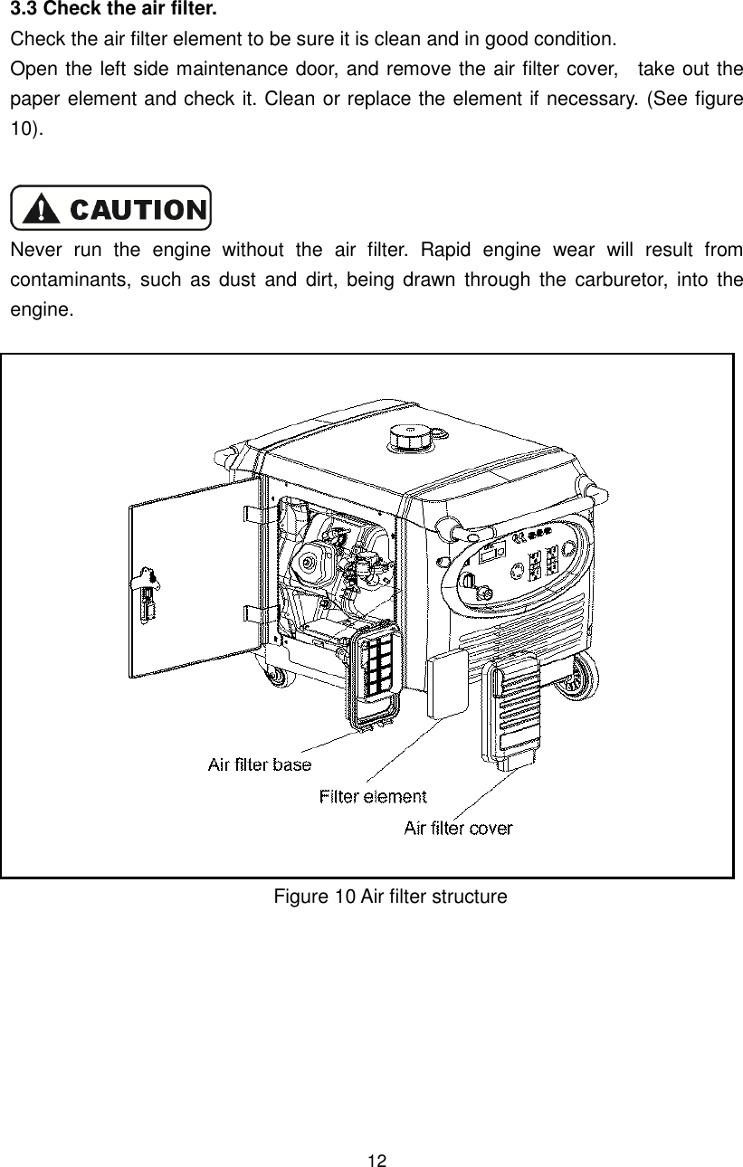
![44 12. SPECIFICATIONS Genset model IG2000i Rated frequency(Hz) 60 Rated voltage(V) 120 Rated current(A) 13.3 Rated speed(r/min) 4500 Rated output power(kVA) 1.6 Max. output power(kVA) 2.0 DC output DC output 12V-5.0A Fuse Equipped No. of phases Single phase Engine Engine model KG158 Engine structure Single cylinder, air-cooled, 4-stroke, in-line arrangement, OHV, gasoline engine Displacement(bore × stroke) 105ml(58×40 mm) Compression ratio 8.5:1 Rated frequency [kW/(r/min)] 2.2/4500 Rated speed(rpm) 4500 Ignition system Transistor electrical ignition Spark plug UR5/A7RTC Start mode Recoil start Fuel type Automotive unleaded gasoline Fuel consumption(g/Kw.h) 420 Lube oil type SAE 10W30 (above CCgrade) Capacity of fuel tank(L) 3.7 Running lasting time(hrs)(under rated output power) 3.5 Noize(d BA/at 7m)(0-load~full-load) 61-73 Dimension (L×W×H)[(mm)] 530×310×430 Net weight [kg] 23 *The declared values shall consider uncertainties due to production variation and measurement procedures.](https://usermanual.wiki/Wuxi-Kipor-Power/21402802/User-Guide-3215689-Page-45.png)

![30 10. SPECIFICATIONS Genset model IG7000e Rated frequency(Hz) 60 Rated voltage(V) 120/240 Rated current(A) 45.8/22.9 Rated speed(r/min) 3600 Rated output power(kVA) 5.5 Max. output power(kVA) 7.0 Engine Engine model KG400GETi Engine structure Single cylinder,4-stroke, air-cooled, OHV, cylinder inclined arrangement, Displacement(bore×stroke) 398ml(89×64 mm) Compression ratio 8.5:1 Ignition system Transistor electrical ignition Spark plug WR7DC Start mode Electrical start Fuel type Automotive unleaded gasoline Oil type Above CD grade or SAE 10W-30, 15W-40 Capacity of fuel tank(L) 20 Running lasting time(hrs)(under rated output power) 6.5 Fuel consumption(g/Kw.h) ≤480 Noise(d BA/at 7m)(0-load~full-load) 65-75* Dimension (L×W×H)[(mm)] 802×495×624(31.57×19.49×24.57) Net weight [kg] 90(198) *The declared values shall consider uncertainties due to production variation and measurement procedures.](https://usermanual.wiki/Wuxi-Kipor-Power/21402802/User-Guide-3215689-Page-86.png)