Wuxi Kipor Power 21402802 Portable Gasoline Engine Driven Generator User Manual IG2000I
Wuxi Kipor Power Co.,Ltd Portable Gasoline Engine Driven Generator IG2000I
User manual
1

1
PREFACE
Thank you for purchasing a Kipor generator.
This manual covers operation and maintenance of the IG2000i generators including
parallel versions.
All information in this publication is based on the latest product information available
at the time of approval for printing.
We reserve the right to make changes at any time without notice and without
incurring any obligation.
No part of this publication may be reproduced without written permission.
This manual should be considered a permanent part of the generator and should
remain with it if it is resold.
Pay special attention to statements preceded by the following words:
Failure to properly follow these precautions can result in
property damage, serious injury or DEATH!
Read all labels and the owner's manual before operating this
generator.
Generators produce carbon monoxide, a poisonous, colorless,
odorless gas that can cause death or serious injury.
Indoor use of a generator can kill quickly. Generators should
be used outdoors only
Generators should be used outdoors only and away from
garages and open windows and protected from rain and snow.
Check for spilled fuel or leaks. Clean and/or repair before use.
Always stop engine before refueling. Wait 5 minutes before
restarting.
Keep any source of ignition away from fuel tank, at all times.
The portable generator is not meant to be used as a
permanent back-up power system for the home. A
permanently installed stationary generator is designed to be
safely used for this specific purpose.

2
Indicates a strong possibility of severe personal injury or death
if instructions are not followed.
Gives helpful information.
If a problem should arise, or if you have any questions about the generator, consult
an authorized dealer.
Our generators are designed to give safe and dependable service if operated
according to instructions. Read and understand the Owner's Manual before
operating the generator. Failure to do so could result in personal injury or equipment
damage.
The Environmental Protection Agency (EPA) recently gave approval for gas stations
to start selling 15% ethanol-blended fuel (E15). E15 gas is now legal for use in cars,
pickups, and SUVs manufactured since 2001. However, E15 IS NOT approved for
off-road engines. This includes engines used in portable generators. Utilizing E15
in outdoor power equipment can cause permanent, irreversible damage, and void
warranties.
The following guidelines will help consumers properly fuel their outdoor power
equipment:
● Read and follow your owner’s manual. The manual will clearly explain what
fuels can be used to ensure a properly functioning product.
● Don’t put any fuel containing more than 10 percent ethanol (E10) into small gas
engine products.
● Check the gas pump to be sure that it is dispensing E10. Some pumps at local
gas stations may offer both E10 and E15, or have blender pumps that dispense
mid-level ethanol fuels for “flex-fuel” automobiles.
● Higher ethanol fuel (E15) may be less expensive than regular (E10) fuel, but
putting E15 into an E10 approved product could cause product failure and void its
warranty.
● Ethanol fuel will go through phase separation if not used immediately, (wicking
moisture from the air) so always keep your extra fuel in an airtight container and
try to avoid storing it in a place that is subject to temperature swings.
● Use a fuel stabilizer if the engine will sit for more than a week without use; this will
help to reduce the ethanol–water separation and potential gumming issues. It is
best to run the engine for at least 20 minutes, under a 50% or more load every 3-4
weeks.
3
CONTENTS
PREFACE ................................................................................................................... 1
1. SAFETY INSTRUCTIONS ...................................................................................... 4
2. SAFETY LABEL LOCATIONS ................................................................................. 6
3. COMPONENT IDENTIFICATION ............................................................................ 7
4. PRE-OPERATION CHECK ................................................................................... 10
5. STARTING THE ENGINE ...................................................................................... 14
6. GENERATOR USE ............................................................................................... 16
7. STOPPING THE ENGINE ..................................................................................... 25
8. PARALLEL GENERATOR OPERATION ................................................................ 27
9. MAINTENANCE .................................................................................................... 31
10. TRANSPORTING/STORAGE.............................................................................. 38
11. TROUBLESHOOTING ........................................................................................ 40
12. SPECIFICATIONS .............................................................................................. 42
13. WIRING DIAGRAMS ........................................................................................... 43
14. WARRANTY........................................................................................................ 44

4
1. SAFETY INSTRUCTIONS
■ This generator is designed to give safe and dependable
service if operated according to instructions.
Read and understand the Owner's Manual before
operating the generator. Failure to do so could result in
personal injury or equipment damage.
■ Exhaust gas contains poisonous carbon monoxide.
Never run the generator in an enclosed area. Never run
the generator near a building or open window.
Be sure to provide adequate ventilation.
■ The muffler becomes very hot during operation and
remains hot for several minutes after stopping the
engine.
Be careful not to touch the muffler while it is hot.
Let the engine cool before storing the generator indoors.
■ The engine exhaust system will be heated during
operation and remain hot immediately after stopping the
engine.
To prevent scalding, pay attention to the warning marks
attached to the generator.
■ Gasoline is extremely flammable and explosive under certain conditions. Refuel
in a well ventilated area with the engine stopped.
■ Keep away from smoking materials, sparks and other sources of combustion
when refueling the generator. Always refuel in a well-ventilated location.
■ Wipe up spilled gasoline immediately.

5
■ Always make a pre-operation inspection before you start the engine. You may
prevent an accident or equipment damage.
■ Place the generator at least three feet or one meter away from buildings or other
equipment during operation.
■ Operate the generator on a level surface to prevent fuel spillage or oil starvation.
■ Know how to stop the generator quickly and understand operation of all controls.
Never permit anyone to operate the generator without proper instructions.
■ Keep children and pets away from the generator when it is in operation.
■ Keep away from rotating parts while the generator is running.
■ The generator is a potential source of electrical shock when misused; do not
operate with wet hands.
■ Do not operate the generator in rain or snow and do not let it get wet.
This device complies with part 15 of the FCC Rules. Operation is subject to the
following two conditions: (1) This device may not cause harmful interference, and (2)
this device must accept any interference received, including interference that may
cause undesired operation.
Changes or modifications not expressly approved by the party responsible for
compliance could void the user's authority to operate the equipment.
This equipment has been tested and found to comply with the limits for a Class B
digital device, pursuant to part 15 of the FCC Rules. These limits are designed to
provide reasonable protection against harmful interference in a residential
installation. This equipment generates uses and can radiate radio frequency energy
and, if not installed and used in accordance with the instructions, may cause harmful
interference to radio communications. However, there is no guarantee that
interference will not occur in a particular installation. If this equipment does cause
harmful interference to radio or television reception, which can be determined by
turning the equipment off and on, the user is encouraged to try to correct the
interference by one or more of the following measures:
—Reorient or relocate the receiving antenna.
—Increase the separation between the equipment and receiver.
—Connect the equipment into an outlet on a circuit different from that to which the
receiver is connected.
—Consult the dealer or an experienced radio/TV technician for help.

6
2. SAFETY LABEL LOCATIONS
These labels warn you potential hazards that can cause serious injury. Read the
labels and safety notes and precautions described in manual carefully.
If a label comes off or becomes hard to read, contact your dealer for a replacement.

7
3. COMPONENT IDENTIFICATION

8
Control panel
Serial number identification and location
The generator serial number identifies your particular unit and is important when
ordering parts and accessories. The number is found on a sticker on the carton and
on the quality certificate in the carton along with the accessories and owner’s manual.
It is also stamped on the engine block visible when the service door is removed.
Product registration is required for any future warranty claims. Register your product
at www.kiporpowerequipment.com

IG2000i: above right of the dipstick
Please record this information below and keep this manual in a safe place along with
the bill of sale.
Serial
Number __________________________________
Date and Place of Purchase __________________________________________
Proof of purchase is required for any future warranty repair. The customer must
supply a copy of the proof of purchase to the qualified Kipor s
requesting warranty.
9
IG2000i: above right of the dipstick
Please record this information below and keep this manual in a safe place along with
Number __________________________________
Date and Place of Purchase __________________________________________
Proof of purchase is required for any future warranty repair. The customer must
supply a copy of the proof of purchase to the qualified Kipor s
ervice center when
Please record this information below and keep this manual in a safe place along with
Date and Place of Purchase __________________________________________
Proof of purchase is required for any future warranty repair. The customer must
ervice center when

4. PRE-
OPERATION CHECK
■
Be sure to check the generator on a level surface with the engine stopped.
1. Check the engine oil level.
■
Using non detergent oil or 2 cycle engine oil could shorten the engine's
Use a high-
detergent, premium quality 4
U.S. automobile manufacturer's requirements for API Service Classification SG/SF.
Select the appropriate viscosity for the average temperature in your
or 10W –
40 should be an acceptable oil for most climates.
DO NOT
use synthetic oil or semi
generator engine. The reasons for this are many, but may include: not allowing the
engine to properly “break-
in” when new, excessive oil use, oil burning, fouled spark
plugs, etc. Engine issues that are caused by the use of synthetic oil may not be
covered under the warranty.
AMBIENT TEMPERATURE
Single
Viscosity
Multi
viscosity
10
OPERATION CHECK
Be sure to check the generator on a level surface with the engine stopped.
1. Check the engine oil level.
Using non detergent oil or 2 cycle engine oil could shorten the engine's
service life.
detergent, premium quality 4
-
stroke engine oil, certified to meet or exceed
U.S. automobile manufacturer's requirements for API Service Classification SG/SF.
Select the appropriate viscosity for the average temperature in your
area.
A 10W
40 should be an acceptable oil for most climates.
use synthetic oil or semi
-
synthetic oil, use only petroleum based oil in your
generator engine. The reasons for this are many, but may include: not allowing the
in” when new, excessive oil use, oil burning, fouled spark
plugs, etc. Engine issues that are caused by the use of synthetic oil may not be
SAE Viscosity Grades
AMBIENT TEMPERATURE
Single
Viscosity
Multi
-
viscosity
Be sure to check the generator on a level surface with the engine stopped.
service life.
stroke engine oil, certified to meet or exceed
U.S. automobile manufacturer's requirements for API Service Classification SG/SF.
A 10W
– 30
synthetic oil, use only petroleum based oil in your
generator engine. The reasons for this are many, but may include: not allowing the
in” when new, excessive oil use, oil burning, fouled spark
plugs, etc. Engine issues that are caused by the use of synthetic oil may not be

11
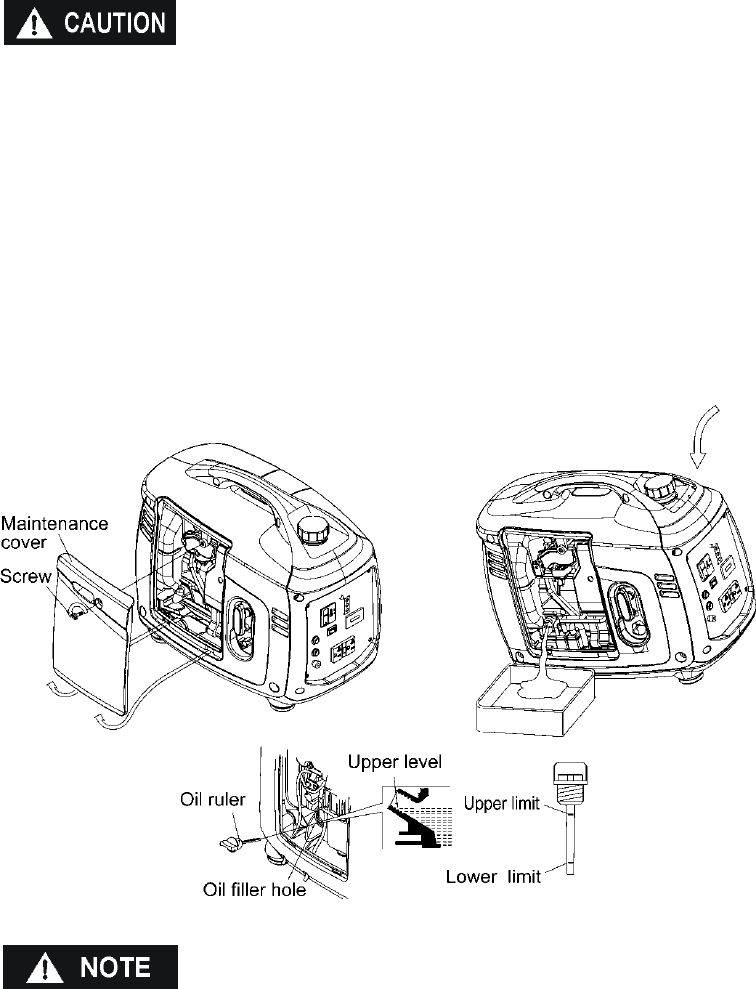
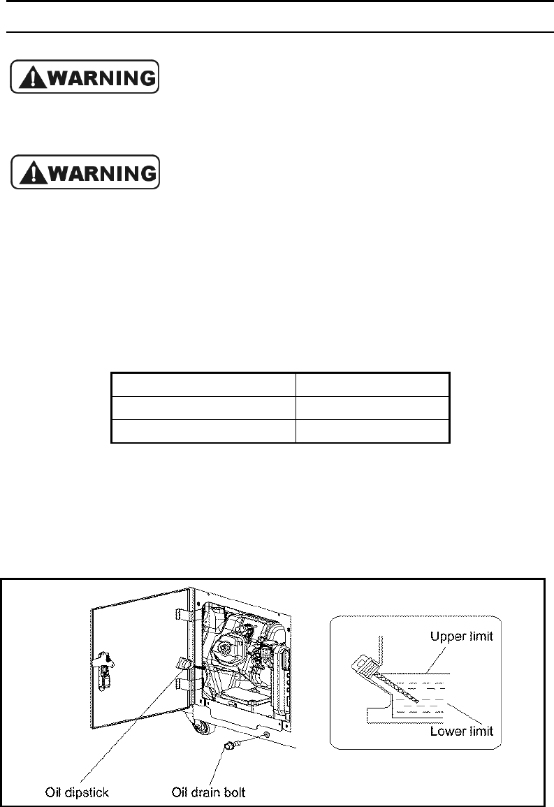
Loosen the cover screw and remove the left side maintenance cover. Remove the oil
filler cap, and wipe the dipstick with a clean rag. Check the oil level by inserting the
dipstick in the filler hole without screwing it in.
If the oil level is below the end of the dipstick, refill the recommended oil up to the top
of the oil filler neck.
■ Running the engine with insufficient oil can cause serious engine damage.
NOTE
: The Low Oil Alarm System will automatically stop the engine before the oil
level falls below the safe limit. However, to avoid the inconvenience of an
unexpected shutdown, it is still advisable to visually inspect the oil level before
operation.
You must screw down the dipstick completely to measure the oil level.
2. Check the fuel level.
Use automotive unleaded regular gasoline only with an octane level no higher than
87 and with no more than 10 % ethanol. A fuel preservative and stabilizer should be
added to any container of stored fuel.
If the fuel level is low, refill the fuel tank until the level reaches the specified mark.
Never use an oil/gasoline mixture or dirty gasoline.
Avoid getting dirt, dust or water in the fuel tank.
After refueling, tighten the fuel filler cap securely.
Oil gauge
Oil FILLER HOLE
UPPER LEVEL
UPPER LEVEL
UPPER LEVEL

12
■ Gasoline is extremely flammable and is explosive under certain conditions.
■ Refuel in a well-ventilated area with the engine stopped. Keep all smoking
materials, sparks, and any other source of combustion away from the generator
during refueling.
■ Do not overfill the fuel tank (there should be no fuel above the upper limit mark).
After refueling, make sure the tank cap is closed properly and securely.
■ Be careful not to spill fuel when refueling. Spilled fuel or fuel vapor may ignite, If
any fuel is spilled, make sure the area is dry before starting the engine.
■ Avoid repeated or prolonged contact with skin or breathing of vapor. KEEP OUT
OF REACH OF CHILDREN.
Gasoline containing alternate fuels
If you decide to use a gasoline containing ethanol, be sure its octane rating is no
lower than the specification. Do not use a blend that contains more than 10% ethanol.
Do not use gasoline containing methanol.
■ Fuel system damage or engine performance problems resulting from the use of
fuels that contain an improper alcohol blend are not covered under warranty.
■ Before buying fuel from an unfamiliar station, Determine if the fuel contains
ethanol and if it does, confirm the type and percentage of ethanol used. If you
notice any undesirable operating symptoms while using a gasoline that contains
ethanol, or one that you think contains ethanol, replace it by a gasoline that you

13
know has the proper blend.
3. Check the air cleaner
Check the air cleaner element to be sure it is clean and in good condition.
Loosen the cover screw and remove the left side maintenance cover.
Press the latch tab on the top of the air cleaner body, remove the air cleaner cover,
check the element. Clean or replace the element if necessary. Picture of foam air
filter cleaning process needed here.
■ Never run the engine without the air cleaner. Rapid engine wear will result from
contaminants, such as dust and dirt, being drawn through the carburetor, into
the engine.

14
5. STARTING THE ENGINE
Before starting the engine, disconnect any load from the AC receptacle.
1. Turn the engine switch to the ON position.
2. Move the choke lever to the START position.
NOTE:
Do not use the choke when the engine is warm or the ambient air temperature is
high.
3. Pull the starter grip until resistance is felt then pull the starter grip briskly
toward the arrow as shown below.
CHOKE LEVER START
START
ON
OFF
ON
ENGINE SWITCH

15
■ Do not allow the starter grip to snap back. Return it slowly by hand.
4. Move the choke lever to the RUN position after the engine warms up.
■ If the engine stops and will not restart, check the engine oil level before further
troubleshooting.
CHOKE LEVER
RUN
RUN

16
6. GENERATOR USE
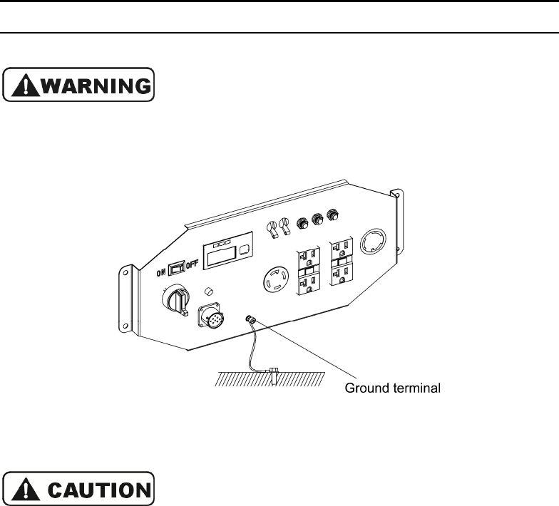
Be sure to ground the generator when loads are connected.
■ To prevent electrical shock from faulty appliances, the generator should be
grounded. Connect a length of heavy cable between the generator's ground
terminal and an external ground source.
■ Connections for standby power to a building's electrical system must be made
by a qualified electrician and must comply with all applicable laws and electrical
codes. Improper connections can allow electrical current from the generator to
back feed into the utility lines. Such back feed may electrocute utility company
workers or others who contact the lines during a power outage. When utility
power is restored the generator may explode, burn, or cause fires in the
building's electrical system.
■ Do not connect the generator to an automatic transfer device. Severe damage to
the inverter module may result.

17
■ The total wattage of all appliances connected must be considered.
■ Do not exceed the current limit specified for any one receptacle.
■ Do not connect the generator to a household circuit. This could cause damage
to the generator or to electrical appliances in the house.
■ Do not modify or use the generator for other purpose than it is intended for. Also
observe the following when using the generator.
■ Do not connect an extension to exhaust pipe.
■ When an extension cable is required, be sure to use a rubber sheathed flexible
cable (IEC 245 or equivalent).
■ Only use an extension cord that meets these specifications: 12 gauge no more
than 100 feet.
■ Keep the generator away from other electric cables or wires such as commercial
power supply lines.
■ The DC receptacle can be used while the AC power is in use. If you use both at
the same time, be sure not to exceed the total power for AC and DC.
■ Most appliance motors require more than their rated wattage for start-up. Motor
start up can be as much as 50% higher of the rated amperage found on the UL tag.
Kipor recommends that this value be calculated into the overall amperage
requirements of the customer.
AC application
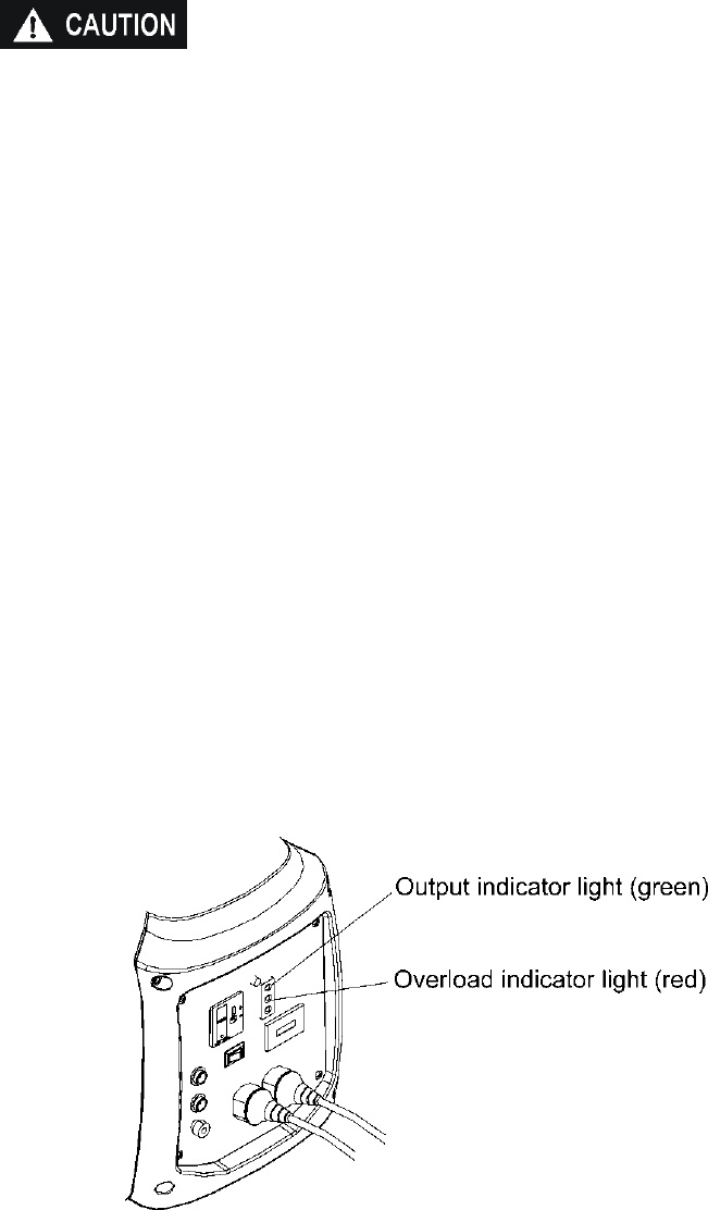
1. Start the engine and make sure only the output indicator light (green) comes on.
2. Confirm that the appliance to be used is switched off, and plug in the appliance.
18
■ Substantial overloading that continuously lights the overload indicator light (red)
may damage the generator. Marginal overloading that temporarily lights the
overload indicator light (red) may shorten the service life of the generator.
■ Be sure that all appliances are in good working order before connecting them to
the generator. If an appliance begins to operate abnormally, becomes sluggish,
or stops suddenly, turn off the generator engine switch immediately. Disconnect
the appliance and examine it for signs of malfunction.
3. In order to insure the optimum output and the maximum service life of the
generator, the generator should run at a 50% load for the first 20 hours.
Output and Overload Indicators
The output indicator light (green) will remain on during normal operating conditions.
If the generator is overloaded or if there is a short in the connected appliance, the
output indicator light (green) will go out, the overload indicator light (red) will
illuminate and current to the connected appliance will be shut off.
Stop the engine if the overload indicator light (red) comes on and investigate the
overload source
■ Before connecting an appliance to the generator, check that it is in good order
and that its electrical rating does not exceed that of the generator. Connect the
power cord of the appliance and start the engine.

19
■ When an electric motor is started, both the overload indicator light (red) and the
output indicator light (green) may go on simultaneously. This is normal if the
overload indicator light (red) goes off after about four (4) seconds. If the overload
indicator light (red) stays on, consult your generator dealer.
Overload Reset Switch
Should the generator overload, AC power will be cut off but the engine will stay
running. Correct the overload condition and then press the overload reset switch on
the front panel. AC power will be restored immediately.
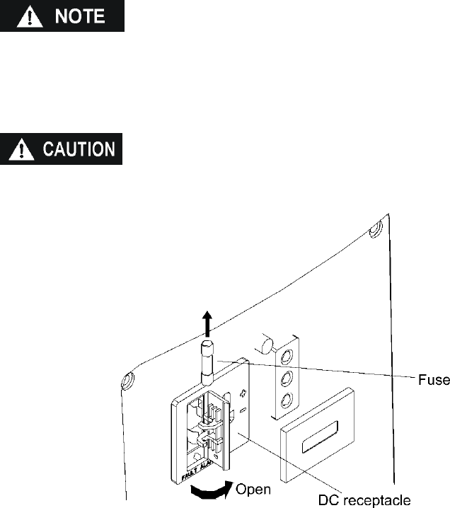
DC Operation
The DC receptacle may be used for charging 12 volt automotive style batteries only,
the no load voltage is 15V-30V.
■ In DC operation, turn the Smart-throttle switch to the OFF position.
Connect the charging cables to the DC receptacle of the generator and then to the
battery terminals.

20
■ To prevent the possibility of creating a spark near the battery, connect the
charging cable first to the generator then to the battery. Disconnect the cable
first at the battery.
■ Before connecting charging cables to a battery that is installed in a vehicle,
disconnect the vehicle’s ground battery cable. Reconnect the vehicle's ground
battery cable after the charging cables are removed. This procedure will prevent
the possibility of a short circuit and sparks if you make accidental contact
between a battery terminal and the vehicle's frame or body.
■ Do not attempt to start an automobile engine with the generator still connected
to the battery. The generator may be damaged.
■ Connect the positive battery terminal to the positive charging cord. Do not
reverse the charging cables, or serious damage to the generator and/or battery
may occur.
■ The battery gives off explosive gases; keep spark, flames and cigarettes away.
Provide adequate ventilation when charging.
21
■ The battery contains sulfuric acid (electrolyte). Contact with skin or eyes may
cause severe burns. Wear protective clothing and a face shield.
-If electrolyte gets on your skin, flush with water.
-If electrolyte gets in your eyes, flush with water for at least 15 minutes and call a
physician.
■ Electrolyte is poisonous.
-If swallowed, drink large quantities of water or milk and follow with milk of
magnesia or vegetable oil and call a physician.
■ KEEP OUT OF REACH OF CHILDREN.
2. Start the engine
■ The DC receptacle may be used while the AC power is in use.
■ An overloaded DC circuit will trip the DC circuit fuse. The fuse must be replaced
before the DC receptacle is operative.
Replace the fuse with one of the same size and rating (5A).
Exceeding the current rating may lead to alternator damage.

22
Low oil alarm system
The low oil alarm system is designed to prevent engine damage caused by an
insufficient amount of oil in the crankcase. Before the oil level in the crankcase falls
below a safe limit, the low oil alarm system will automatically shut down the engine
(the engine switch will remain in the ON position).
If the low oil alarm system shuts down the engine, the low oil alarm indicator light
(red) will come on when you operate the starter and the engine will not run. If this
occurs add engine oil.
Air Conditioning Operation
When running in parallel (see section 8) the combination of an IG2000i model can
start and run most 13,500 BTU Air conditioners. An IG2000i models will start and run
most 15000 BTU units. For best results, the SMART throttle switches should be in
the off position. Bring the generators to normal operating temperatures before
applying the air conditioning load. Always allow a 2 minute wait period when
manually cycling an air conditioner off and on. A longer wait period may be required
under unusually hot weather conditions. Additionally, all other loads should be turned
off until the air conditioner has started and is performing normally. It is also important
to follow the air conditioner manufacturer's instructions for starting and restarting for
proper operation. Some air conditioner manufacturers offer a start capacitor or
rapid start kit as an extra cost option. The lack of a start capacitor can cause the air
conditioner to draw too high a starting current and overload the generators. Contact
your air conditioner dealer if you consistently have problems starting your air
conditioner with the generators in parallel.

23
Smart Throttle System
When the smart throttle switch is placed in the on position, engine speed is kept at
idle automatically when the electrical load is disconnected and returns to the proper
speed to match the power of the electrical load when the load is reconnected. This
position is recommended to minimize fuel consumption while in operation.
If running the generator at full output, turn the smart throttle switch to the “off”
position.
■ The Smart throttle system does not operate effectively if the electrical appliance
requires constant fluctuations in power.
■ When high electrical loads are connected simultaneously, turn the Smart throttle
switch to the OFF position to reduce voltage fluctuation or shutdown.
■ In DC operation, turn the Smart throttle switch to the OFF position.
OFF:
Smart throttle system does not operate. Engine speed varies with the load.

24
High altitude operation
At higher altitudes, the standard carburetor air-fuel mixture will be excessively rich.
Performance will decrease, and fuel consumption will increase. Power output will
decrease 3.5% for each 1000 feet (305 meters) above sea level.
High altitude performance can be improved by installing a smaller diameter main fuel
jet in the carburetor. If you always operate the generator at altitudes higher than
5000 feet or 1500 meters above sea level, have your authorized dealer install a high
altitude main jet.
Even with suitable carburetor jetting, engine horsepower will decrease approximately
3.5% for each 1000 feet or 305 meter increase in altitude. The affect of altitude on
the horsepower will be greater than this if no carburetor modification is made.
■ Operation of the generator at an altitude lower than the carburetor is jetted for
may result in reduced performance, overheating, and serious engine damage
caused by an excessively lean air/fuel mixture.
■ Be sure to have any modification reversed at lower altitudes.
Temperature
High temperature adversely affects generator operation. Generator performance will
decrease 1% for each 10°F (5.5°C) increase in temperature above 85°F (29°C) The
normal operating range of this generator is -20° to 113° F (-29° to 45°C)
■ Do not operate the generator when the ambient temperature is below -20°F
(-29°C)
■ Do not operate the generator when the ambient temperature exceeds 113°F
(45°C)

25
7. STOPPING THE ENGINE
To stop the engine in an emergency, turn the engine switch to the OFF position.
IN NORMAL USE:
1. Switch off the connected equipment and pull the inserted plug out.
2. Turn the engine switch to the OFF position
26

27
Optional Remote stop:
Shut off the connected equipment, press stop button, the genset will be stopped.
The max. remote control distance:65feet.
Stop button
Remote control key

8. Operating t
wo generators in parallel
Two generators run in parallel
Two IG2000i digital
generators running in
parallel can increase the output power of
generators.
28
wo generators in parallel
Two generators run in parallel
:
generators running in
parallel can increase the output power of
Figure 1
29
Procedures to run 2 generators with a
parallel box:
1. Prepare two KIPOR IG2000 I digital
generators.
Figure 2
Note:
Be sure the two generators are shut off.
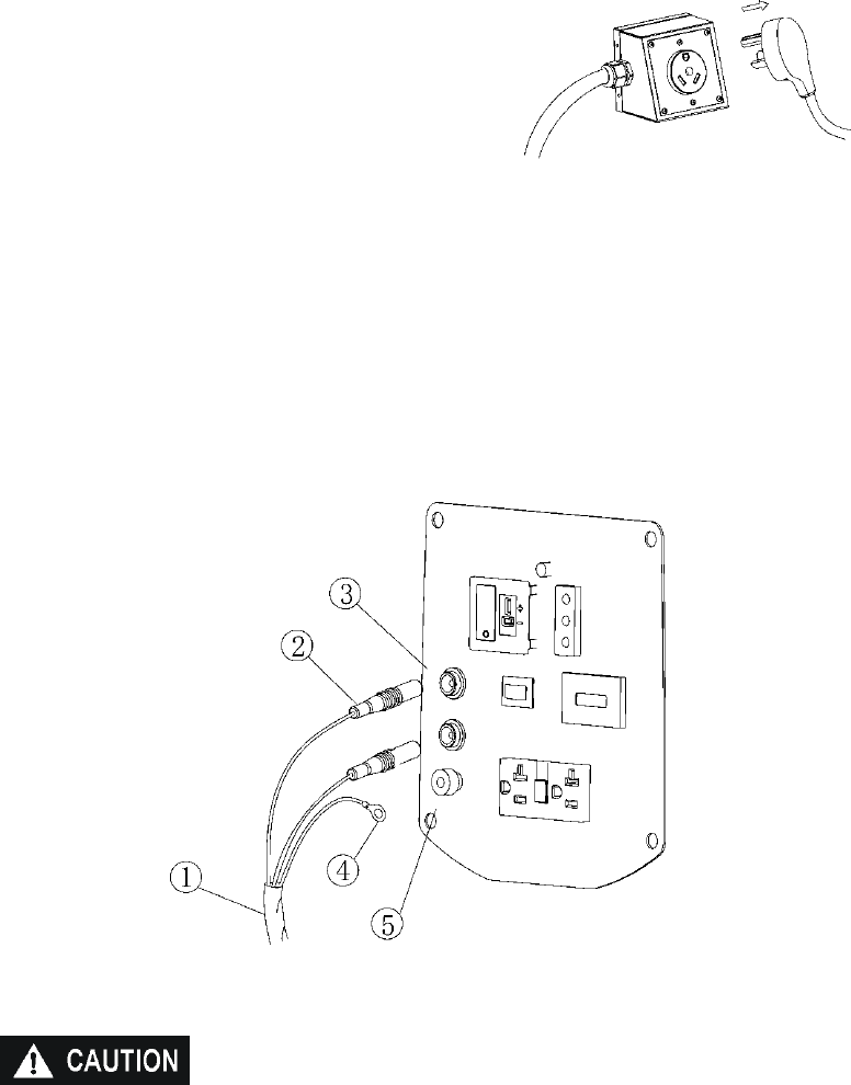
2. Insert the connecting plug
②
of the parallel cable
①
to PARALLEL OUTPUT
receptacle
③
on the controller panel of each generator
(
See figure 3
)
3. Connect the grounding terminal
④
of the parallel cable to the grounding terminal
⑤
of each generator
(
See figure 3
)
Figure 3
Be sure all the electrical equipment is grounded. See
⑧
.
Be sure each generator is on a stable level surface.
4. Start the two generators:
The start procedure is the same as normal start procedure. (Refer to the section
introducing how to start the engine in this manual)

30
Before starting, make sure that the PARALLEL OUTPUT on each controller
panel has been inserted to the parallel cable. Otherwise, damage to the
generator may occur.
5. Insert the electrical equipment plug
⑦
into the parallel cable receptacle
⑥
and
turn the power switch of the electrical equipment to the on position. (See figure 4
)
Figure 4
The power of electrical equipment shall not exceed the rated output of the
parallel receptacle.
The parallel receptacles used in different area are different. Refer to Parallel
receptacle usage manual.

31
Shut off the generator:
1. Turn off the power switch of the electrical equipment; pull the plug out of the
parallel receptacle.
2. Shut off the two generators.
3. If two generators parallel are not used, be sure to remove the cable from
PARALLEL OUTPUT.
Kipor IG2000i parallel cable is only suitable for two KIPOR IG2000i generators
being run simultaneously.
Always use Kipor parallel output cable on IG2000i.
When using the parallel cable, safely insert the plug into the receptacle.
When running two generators in parallel, DO USE the receptacle of parallel
cable for power output, Do not use the receptacle on the control panel.
Before starting the generator, connect the parallel output cable, after the
generators stopped, disconnect the parallel output cable. Never connect or
disconnect the parallel output cable when the generators are running.
If the parallel output cable is still connected when one generator has stopped
running, stop the running generator and remove the parallel box.
If only one generator is operated, make sure the parallel output cable is
disconnected.
When the two generators are running separately, make sure the parallel output
cable is disconnected.
Before operating the generator, read the manual carefully.

32
9. MAINTENANCE
The purpose of the maintenance and adjustment schedule is to keep the generator
in the best operating condition.
Inspect or service as scheduled in the table below.
■ Shut off the engine before performing any maintenance. If the engine must be
run, make sure the area is well ventilated. The exhaust contains poisonous carbon
monoxide gas.
■
Use genuine our parts or their equivalent. The use of replacement parts which
are not of equivalent quality may damage the generator.
■
When repairing or replacing the accessories of emission control system, make
sure to use the EPA standard accessories.
Emission control system
Emission source
Exhaust gas contains carbon monoxide, nitrous oxide (NOx), and hydrocarbons. It is
very important to control the emissions of NO
X
and hydrocarbons as they are a major
contributor to air pollution. Carbon monoxide is a poisonous gas. The emission of
fuel vapors is a source of pollution as well. The Kipor generator engine utilizes a
precise air-fuel ratio and emission control system to reduce the emissions of carbon
monoxide, NO
X
, hydrocarbons, and evaporative fuel emissions.
Regulation
Your engine has been designed to meet current Environmental Protection Agency
(EPA) and the California Air Resources Board (CARB) clean air standards if so
equipped and designated. The regulations dictate that the manufacturer provide
operation and maintenance standards regarding the emission control system. Tune
up specifications are provided in the Specifications section and a description of the
emission control system may be found in an appendix to this manual, Adherence to

33
the following instructions will ensure your engine meets the emission control
standards.
Modification
Modification of the emission control system may lead to increased emissions.
Modification is defined as the following:
Disassemble or modify the function or parts of the intake, fuel or
exhaust system.
Modify or destroy the speed governing function of the generator.
Engine faults that may affect emission
Any of the following faults must be repaired immediately. Consult with your
authorized Kipor service center for diagnosis and repair:
Hard starting or shut down after starting
Unstable idle speed
Shut down or backfire after applying an electrical load
Backfire.
Black smoke and/or excessive fuel consumption
Replacement parts and accessories
The parts making up the emission control system applied to Kipor engine have been
specifically approved and certified by the regulatory agencies. You can trust the
replacement parts supplied by Kipor have been manufactured to the same
production standard as the original parts. The use of replacement parts or
accessories which are not designed by Kipor may affect the engine emission
performance. The manufacturers of replacement parts and accessories have the
responsibility to guarantee that their replacement products will not adversely affect
emission performance.
Maintenance
Maintain the generator according to the maintenance schedule in this section.
Service items more frequently when used in dusty areas, or under conditions of high
load, temperature, and humidity.
Air Quality Index (only for California certified models)
CARB requires that an air quality index label be attached to every certified engine
showing the engine emission information for the emission duration period. The label
is provided for the user to compare the emission performance of different engines.
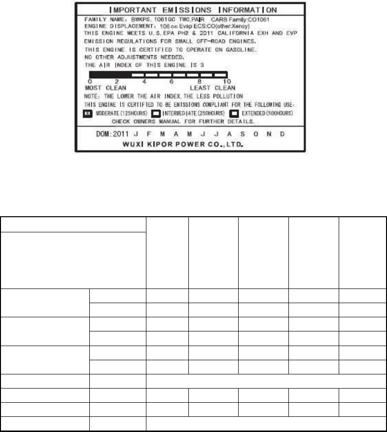
34
The lower the air index, the better the engine emission performance. The description
of durability is helpful for the user to learn the engine emission duration period and
the service life of emission control system. Refer to the warranty section of this
owner’s manual for more information.
The air quality index label is designed to be permanently affixed to the generator and
removal should not be attempted.
Maintenance Schedule
REGULAR SERVICE PERIOD(1)
EACH
USE
FIRST
MONTH
OR
20HRS
EVERY 3
MONTHS
OR
50HRS
EVERY 6
MONTHS
OR
100 HRS
EVERY
YEAR
OR
200 HRS
ITEM
Perform at every indicated month
or operating hour interval, which-
ever comes first.
Engine oil Check level ○
Change ○ ○
Air cleaner Check ○
Clean ○(1)
Spark plug Clean-adjust ○
Replace ○
Combustion chamber Clean ○ Every 300Hrs. (2)
Valve clearance Clean-adjust ○(2)
Fuel tank and filter Clean ○(2)
Fuel lines Check Every 2 years (Replace if necessary) (2)
NOTE: (1) Service more frequently when used in dusty areas.
(2) These items should be serviced by your servicing dealer unless you have
the proper tools and are mechanically proficient. Refer to the shop manual
for service procedures.
(3) For commercial use, log hours of operation to determine proper
maintenance intervals.
35
1. CHANGING OIL
Drain the oil while the engine is still warm to assure rapid and complete draining.
■ Make sure to turn the engine switch and the fuel cap vent lever OFF before
draining.
1. Loosen the cover screw and remove the left side maintenance cover.
2. Remove the oil filler cap.
3. Drain dirty oil into a container thoroughly. See note below concerning proper
disposal.
4. Refill with the recommended oil, and check the oil level.
5. Reinstall the left side maintenance cover and tighten the cover screw securely.
Engine oil capacity: 0.42 qt. (0.4L)
■ Please dispose of used motor oil in a manner that is compatible with the
environment and local disposal regulations. Do not throw it in the trash or pour it
on the ground.
36
2. AIR CLEANER SERVICE IG2000i
A dirty air cleaner will restrict air flow to the carburetor. To prevent carburetor
malfunctioning, service the air cleaner regularly. Service more frequently when
operating the generator in extremely dirty areas.
■Do not use gasoline or low flash point solvents for cleaning. They are flammable
and explosive under certain conditions.
■Never run the generator without the air cleaner, otherwise rapid engine wear may
result.
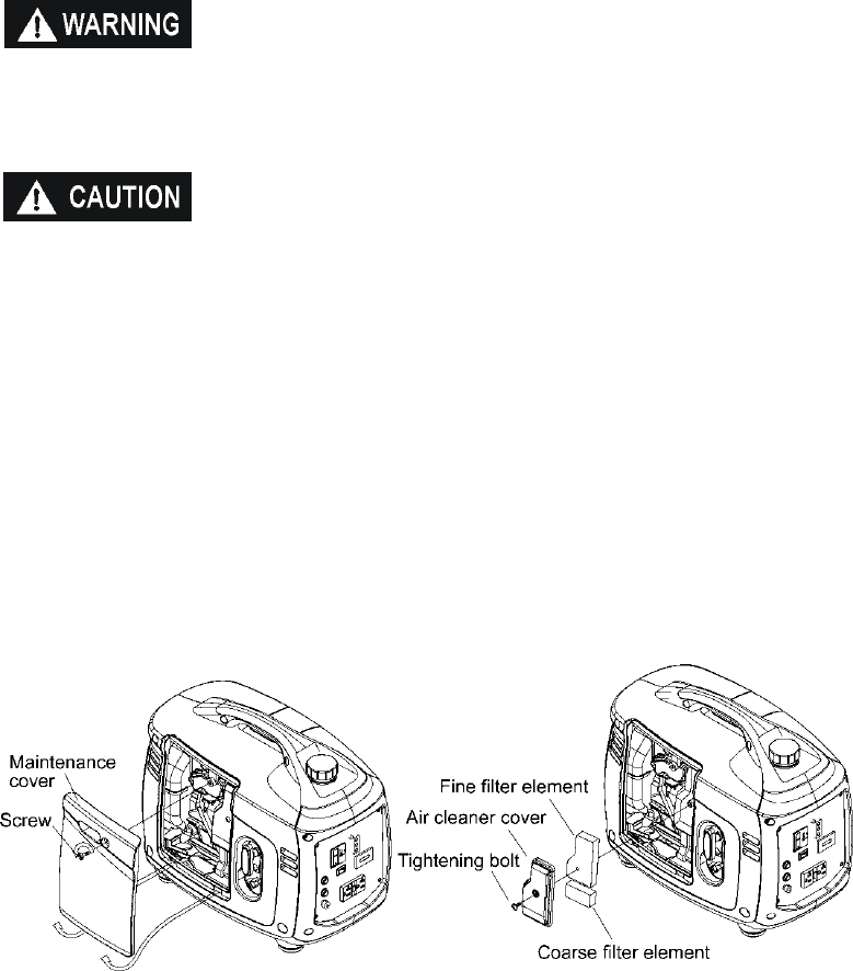
1. Loosen the cover screw and remove the left side maintenance cover.
2. Remove the air cleaner cover and remove the fine and filter coarse elements.
3. Wash the filter elements in a non-flammable or high flash point solvent and dry it
thoroughly.
4. Soak the filter elements in clean engine oil and squeeze out the excess oil.
5. Reinstall the coarse and fine air cleaner filter elements and the air cleaner cover.
Tighten the cover screw securely.
6. Reinstall the maintenance cover and tighten the cover screw securely.
37
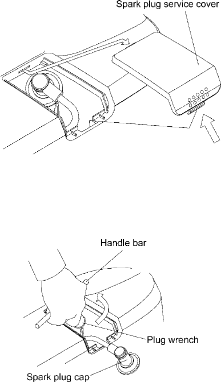
3. SPARK PLUG MAINTENANCE
To ensure proper engine operation, the spark plug must be properly gapped and free
of deposits.
1. Remove the spark plug maintenance cover.
2. Remove the spark plug cap.
3. Clean any dirt from around the spark plug base.
4. Use the wrench provided to remove the spark plug
5. Visually inspect the spark plug. Discard it if the insulator is cracked or chipped.
Clean the spark plug with a wire brush if it is to be reused.
6. Measure the plug gap with a feeler gauge.
The gap should be 0.024-0.028in (0.6-0.7mm). Correct as necessary by carefully
bending the side electrode.

38
7. Install the spark plug carefully, by hand, to avoid cross-threading.
8. After a new spark plug has been seated by hand, it should be tightened 1/2 turn
with a wrench to compress its washer. If a used plug is being reinstalled, it should
only require 1/8 to 1/4 turn after being seated.
9. Reinstall the spark plug cap on the spark plug securely.
10. Reinstall the spark plug maintenance cover.
■The spark plug must be securely tightened. An
improperly tightened plug can become very hot and
possibly damage the generator.
■Never use a spark plug with an improper heat range.

39
10. TRANSPORTING and STORAGE
To prevent fuel spillage when transporting or during temporary storage, the
generator should be secured upright in its normal operating position with the engine
switch placed in the OFF position.
When transporting the generator:
■ If you must transport the generator in a vehicle, drain all fuel from the generator.
■ Do not operate the generator while it is on or in a vehicle. Take the generator out
of the vehicle and use it in a well ventilated area.
■ Avoid a storage area exposed to direct sunlight when putting the generator on a
vehicle. If the generator is left in an enclosed vehicle for many hours, high
temperature inside the vehicle could cause residual fuel to vaporize resulting in
a possible explosion.
■ Do not drive on a rough road for an extended period with the generator on
board.
Before storing the unit for an extended period:
1. Be sure the storage area is free of excessive humidity and dust.
2. Drain the fuel.
■ Gasoline is extremely flammable and explosive under certain conditions.
■ Do not smoke or allow flames or sparks in the area.

40
Periodic running of the Generator
It is essential that the generator be periodically run on a regular basis. This will
prevent the accumulation of varnish or sludge in the fuel system and also remove
moisture from the generator windings. Additionally the engine seals and moving
components are lubricated. Periodically running the generator at least at 1/2 the load
for 60 minutes each month. Gasoline fuel treatments to prevent contamination of
your fuel supply are available from your dealer. Fuel varnishing necessitating
replacement of the carburetor is not a warrantable failure.
Storage
a. Drain all gasoline from the fuel tank into an approved gasoline container.
b. Turn the engine switch ON, and loosen the carburetor drain screw and drain the
gasoline from the carburetor into a suitable container. Dispose of properly.
c. With the drain screw loosened remove the spark plug cap and pull the starter
grip 3 to 4 times to drain the gasoline from the fuel pump.
d. Turn the engine switch to the OFF position, and tighten the drain screw securely.
e. Reinstall the spark plug cap on the spark plug securely.
f. Change the engine oil.
g. Remove the spark plug and pour about a tablespoon of clean engine oil into the
cylinder. Crank the engine several revolutions to distribute the oil and then
reinstall the spark plug.
5. Slowly pull the starter grip until resistance is felt. At this point, the piston is
coming up on its compression stroke and both the intake and exhaust valves are
closed. Storing the engine in this position will help to protect it from internal
corrosion.

41
11. TROUBLESHOOTING
Engine will not start:
To check:
1) Remove the spark plug cap and clean
any dirt from around the spark plug.
2) Remove the spark plug and install the
spark plug in the plug cap.
3) Set the plug side electrode on the cylinder
head to ground.
4) Pull the recoil starter, sparks should jump
across the gap.
Is there fuel in the tank?
NO Refuel the fuel tank
YES
Is the engine switch on? Turn the engine switch on.
Is the enough oil in the engine? Add the recommended oil.
Is there a spark from
the spark plug?
Replace the
spark plug.
Still no
spark
YES
YES
NO
NO
NO
■
Be sure there is no spilled
fuel around the spark plug.
Spilled fuel may ignite.
WARNING
If the engine still does not
start, take the generator to an
authorized dealer.

42
Appliance does not operate:
Is the output indicator light ON?
Is the overload indicator light
on?
Take the generator to an
authorized dealer.
Check the electrical appliance
or equipment for any
defects.
Take the generator to an
authorized dealer.
■
Replace the
appliance or equipment
■
Take the electrical appli-
ance or equipment to an
electrical shop for repair
Stop and restart the engine.
YES
DEFECTS
NO DEFECTS
NO
NO
YES
YES
Replace the fuse

43
No electricity at the DC receptacle:
Take the generator to an
authorized dealer.
Is the DC circuit fuse blown?
NO

44
12. SPECIFICATIONS
Genset model IG2000i
Rated frequency(Hz) 60
Rated voltage(V) 120
Rated current(A) 13.3
Rated speed(r/min) 4500
Rated output power(kVA) 1.6
Max. output power(kVA) 2.0
DC output
DC output 12V-5.0A
Fuse Equipped
No. of phases Single phase
Engine
Engine model KG158
Engine structure Single cylinder, air-cooled, 4-stroke, in-line
arrangement, OHV, gasoline engine
Displacement(bore × stroke) 105ml(58×40 mm)
Compression ratio 8.5:1
Rated frequency [kW/(r/min)] 2.2/4500
Rated speed(rpm) 4500
Ignition system Transistor electrical ignition
Spark plug UR5/A7RTC
Start mode Recoil start
Fuel type Automotive unleaded gasoline
Fuel consumption(g/Kw.h) 420
Lube oil type SAE 10W30 (above CCgrade)
Capacity of fuel tank(L) 3.7
Running lasting time(hrs)(under rated
output power) 3.5
Noize(d BA/at 7m)(0-load~full-load)
61-73
Dimension (L×W×H)[(mm)] 530×310×430
Net weight [kg] 23
*The declared values shall consider uncertainties due to production variation and
measurement procedures.

45
13. WIRING DIAGRAM
IG2000i Wiring Diagram

46
14. WARRANTY
Kipor Power Equipment, Inc. Warranty
Product registration: Registration is required for warranty coverage, register your
product by completing the registration form found with the owner’s manual or go
to www.kiporpowerequipment.com
LENGTH OF WARRANTY
Kipor Products are covered by this warranty from the date of original retail purchase for a
period of three (3) years or 300 hours for residential use and for one (1) year or 300 hours
for commercial and rental applications. If batteries are shipped with generators, they are
warranted by the manufacturer. The warranty coverage is continual from the original
date of purchase, and does not restart upon the replacement of any part or complete unit.
Individual parts replaced at any point during the warranty period are only eligible for
warranty coverage for the balance of the original warranty period and owner.
ELIGIBILITY
To be eligible for warranty service, the product must be purchased in the United States or
Canada from an authorized dealer. This warranty applies to the original retail purchaser
only and is not transferable. Proof of purchase is required. Goods exported from
North America as well as goods sold at auction are excluded from warranty coverage.
Warranty coverage will only be provided by authorized dealers in the United States and
Canada.
COVERAGE
Parts and labor will be covered for any failure that is proven to be a failure of material or
workmanship under normal use during the applicable warranty time period. It is the
responsibility of the end user to return the product to the nearest authorized repair center
as directed by the warranty administration center. In the event that the generator is
deemed not repairable or the necessary repair would be economically unfeasible, the
Kipor distributor will pay for shipping of the unit from the repair center to the designated
distributor facility and the shipping of a replacement unit. Kipor or its distributor reserves
the right to repair or replace these parts at its option. The return of defective parts may
be requested. Anything replaced under warranty becomes the property of Kipor.
TO OBTAIN WARRANTY SERVICE
Contact any authorized dealer or contact our national customer service center at:
Phone: 888-645-0197 E-mail: service@kiporpowerequipment.com
If contacting us by e-mail, be sure to include a description of the problem as well as all
return contact information such as address, phone number, fax number, e-mail, etc.
47
Engine serial number and proof of purchase are required.
EXCLUSIONS
This warranty does not extend to parts affected or damaged by accident and/or collision,
normal wear, fuel contamination or degradation, use in an application for which the
product was not designed or any other misuse, neglect, incorporation or use of
unsuitable attachments or parts, unauthorized alteration, or any causes other than
defects in material or workmanship. This warranty does not extend to normal
maintenance items such as belts, hoses, spark plugs and filters past the first scheduled
replacement or service interval for these items, whichever comes first. Kipor will pay for
minor adjustments for a period of ninety days from the purchase date of the generator.
DISCLAIMER OF CONSEQUENTIAL DAMAGE AND LIMITATION OF IMPLIED
WARRANTIES
Kipor denies any responsibility for loss of time or use of the product, transportation,
commercial loss, or any other incidental or consequential damage. Any implied
warranties are limited to the duration of this written limited warranty.
Some states do not allow limitations on how long an implied warranty lasts and/or do not
allow the exclusion or limitation of incidental or consequential damages. Therefore, the
above exclusions and limitations may not apply to you. This warranty gives you specific
legal rights and you may also have other rights which vary from state to state.
Emission Control System Warranty
In the United States and California, new small off-road engines must be designed, built
and equipped to meet stringent emission standards. Kipor must warrant the emission
control system on your generator engine for the periods of time listed below provided
there has been no abuse, neglect, improper maintenance, or unauthorized application of
your small off-road engine.
If a warrantable condition is determined, Kipor Power Equipment will repair your small
off-road engine at no cost to you including diagnosis, parts, and labor.
Coverage
Emissions control parts on the engine are warranted for a period of two years, subject to
provisions set below. If any covered part on your engine is defective, the part will be
repaired or replaced by Kipor Power Equipment.
Owner’s Responsibilities
You are responsible to maintain the engine as defined in your Kipor Generator Owner’s
Manual. Kipor recommends that you retain all record/receipts covering maintenance on

48
your engine, but Kipor Power Equipment cannot deny warranty claims based on a lack of
receipts or for your failure to perform all scheduled maintenance. You may be denied
warranty coverage if a part has failed due to abuse, neglect, improper maintenance, or
unapproved applications.
You are required to bring your generator to an authorized Kipor generator dealer for
repairs as soon as a problem exists. For emissions warranty service, contact your
nearest dealer. For a listing visit www.kiporpowerequipment.com or by calling
888-645-0197.
Emission Control System Parts
Coverage under this warranty extends only to the emissions control parts listed below:
1. Fuel System
A. Carburetor gaskets
B. Fuel lines, fittings, and clamps
C. Fuel filter (if equipped)
D. Fuel pump (if equipped)
E. Carburetor
2. Intake System
A. Air cleaner assembly
B. Intake manifold
3. Ignition System
A. Ignition coil
B. Spark plug
4. Exhaust System
A. Catalytic converter (if equipped)
B. Exhaust manifold
C. Gaskets
5. Crankcase Breather System
A. Breather assembly
B. Breather tube
6. Air Injection System
A. Secondary air injection valve
7. Fuel Tank Evaporative Emissions Control System
A. Fuel tank
B. Fuel cap
C. Carbon canister and brackets
8. Miscellaneous Items used in above
A. Hoses, connectors, and fittings
B. Electrical switches
Warranty Provisions

49
1. Claims Warranty claims shall be filed in accordance with the provisions of the Kipor
warranty and policies established with the authorized repair center network.
2. Exclusions Warranty coverage shall be denied for failure of an emissions control
system part caused by abuse, neglect, improper maintenance or application as
described in the Kipor Generator Owner’s Manual. Additionally, coverage may be denied
for the use of add-on parts, modified parts, or parts that are not equivalent to original
Kipor generator parts in performance and durability.
3. Length of Coverage Kipor Power Equipment warrants to the original retail purchaser
and each subsequent owner that the emissions control system shall be free of defects in
materials and workmanship for a period of two years from the date of the original retail
customer.
4. Repair or Replacement Cost Repair or replacement of any emissions control system
part will be repaired at no charge to the owner including diagnostic labor which would
determine an emissions control system defect exists if the repair is performed at an
authorized Kipor repair service center.
5. Consequential Damage Repairs will extend to any other engine part damaged by the
failure of any emission control system part.
6. Maintenance The emissions control system and associated parts are warranted for
defects during the warranty period only. The warranty does not cover any replacement of
parts that are replaced as required by the maintenance schedule in the Kipor Generator
Owner’s Manual. Any replacement part that is equivalent in function and durability may
be used for maintenance or repairs.
Questions
If you have any questions regarding your rights and responsibilities under this emissions
system warranty, you may contact Kipor Aftermarket Support Service Center.
By email: service@kiporpowerequipment.com
By phone: 888-645-0197
By mail: Kipor Power Equipment, 13009 SE Jennifer St. #105 Clackamas, OR 97015
50
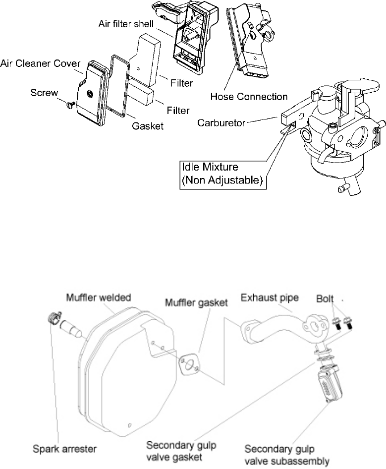
Intake System and Carburetor
Exhaust System

51
Fuel System
Gas Cap
Washer
Sleeve
Bushing
Gasket
Washer
Cotter Pin
Retention Hook
Fuel Indicator
Strainer
Gas Cap
Sleeve
Vent Hose
Fuel Tank Cover
Fuel Tank
Certification No.


PREFACE
Thank you for purchasing our generators.
This manual covers operation and maintenance of the IG7000e generator.
All information in this publication is based on the latest product information available
at the time of approval for printing.
We reserve the right to make changes at any time without notice and without incurring
any obligation.
No part of this publication may be reproduced without written permission.
This manual should be considered a permanent part of the generator and should
remain with it if it is resold.
Pay special attention to statements preceded by the
following words;
Failure to properly follow these precautions can result in
property damage, serious injury or DEATH!
Read all labels and the owner's manual before operating
this generator.
Operate only in well ventilated areas. Exhaust gas
contains poisonous carbon monoxide, and can be deadly.
Always stop engine before refueling. Wait 5 minutes
before restarting.
Check for spilled fuel or leaks. Clean and/or repair before
use.
Keep any sources of ignition away from fuel tank, at all
times.
Indicates a strong possibility of severe personal injury or
death if instructions are not followed.
Indicates a possibility of personal injury or equipment
damage if instructions are not followed.
NOTE: Gives helpful information.
If a problem should arise, or if you have any questions about the generator, consult an
authorized dealer.
The generators are designed to give safe and
dependable service if operated according to instructions.
Read and understand the Owner's Manual before
operating the generator. Failure to do so could result in
personal injury or equipment damage
Contents
1. SAFETY INSTRUCTIONS .................................................................................... 1
2. COMPONENT IDENTIFICATION .......................................................................... 4
3. PRE-OPERATION CHECK ................................................................................... 8
4. STARTING THE ENGINE ................................................................................... 12
5. GENERATOR USE ............................................................................................. 14
6. STOPPING THE ENGINE ................................................................................... 20
7. MAINTENANCE .................................................................................................. 21
8. TRANSPORTING & STORAGE .......................................................................... 26
9. TROUBLE SHOOTING ....................................................................................... 27
10. SPECIFICATIONS ............................................................................................ 29
11. ELECTRICAL PRINCIPLE DIAGRAM ............................................................... 30
12. TRUNDLE INSTALLATION ............................................................................... 31
13. APPENDIX ........................................................................................................ 32

1
1. SAFETY INSTRUCTIONS
Operate carefully and make sure users and others safety.
The generators are designed to give safe and
dependable service if operated according to instructions.
Read and understand the Owner's Manual before
operating the generator. Failure to do so could result in
personal injury or equipment damage.
Exhaust gas contains poisonous carbon monoxide.
Never run the generator in an enclosed area.
Be sure to provide adequate ventilation.
The muffler becomes very hot during operation and
remains hot for a while after stopping the engine.
Be careful not to touch the muffler while it is hot.
Let the engine cool before storing the generator indoors.
The engine exhaust system will be heated during
operation and remain hot immediately after stopping the
engine. To prevent scalding, pay attention to the warning
marks attached to the generator.
Gasoline is extremely flammable and explosive under
certain conditions. Refuel in a well ventilated area with
the engine stopped.
Keep away from cigarette, smoke and sparks when
refueling the generator, Always refuel in a well-ventilated
location.
Wipe up spilled gasoline at once.
Restrict application of generator in high-hazard risk to
causing fire area.

2
Connections for standby power to a building's electrical
system must be made by a qualified electrician and must
comply with all applicable laws and electrical codes.
Improper connections can allow electrical current from
the generator to back feed into the utility lines. Such back
feed may electrocute utility company workers or others
who contact the lines during a power outage, and when
utility power is restored, the generator may explode, burn,
or cause fires in the building's electrical system.
Always make a pre-operation inspection (page 9) before
you start the engine. You may prevent an accident or
equipment damage.
Place the generator at least 1m (3ft) away from buildings
or other equipment during operation.
Operate the generator on a level surface. If the generator
is tiled, fuel spillage may result.
Know how to stop the generator quickly and understand
operation of all the controls. Never permit anyone to
operate the generator without proper instructions.
Keep children and pets away from the generator when it
is in operation.
Keep away from rotating parts while the generator is
running.
The generator is a potential source of electrical shocks
when misused; do not operate with wet hands.
Do not operate the generator in rain or snow and do not
let it get wet.
This device complies with part 15 of the FCC Rules. Operation is subject to the
following two conditions: (1) This device may not cause harmful interference, and (2)
this device must accept any interference received, including interference that may
cause undesired operation.
Changes or modifications not expressly approved by the party responsible for
compliance could void the user's authority to operate the equipment.
3
This equipment has been tested and found to comply with the limits for a Class B
digital device, pursuant to part 15 of the FCC Rules. These limits are designed to
provide reasonable protection against harmful interference in a residential installation.
This equipment generates uses and can radiate radio frequency energy and, if not
installed and used in accordance with the instructions, may cause harmful
interference to radio communications. However, there is no guarantee that
interference will not occur in a particular installation. If this equipment does cause
harmful interference to radio or television reception, which can be determined by
turning the equipment off and on, the user is encouraged to try to correct the
interference by one or more of the following measures:
—Reorient or relocate the receiving antenna.
—Increase the separation between the equipment and receiver.
—Connect the equipment into an outlet on a circuit different from that to which the
receiver is connected.
—Consult the dealer or an experienced radio/TV technician for help.
4
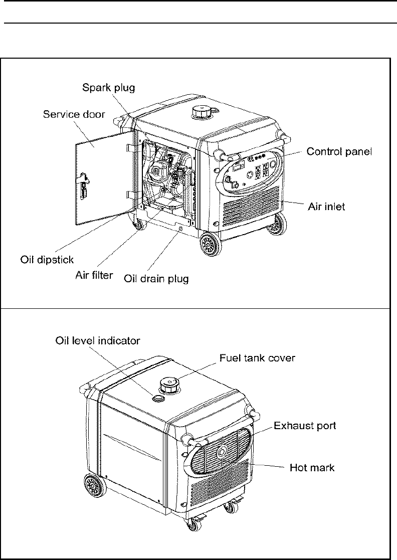
2.COMPONENT IDENTIFICATION
2.1 Outline drawing (Figure 1)
Figure 1 Outline drawing

5
2.2 Inlet System
Figure 2
2.3 CARB Evaporative Control System
Figure 3

6
2.4 Carbon Canister Location (CARB only)
Figure 4
2.5 Control panel (See figure 5)
Figure 5
7
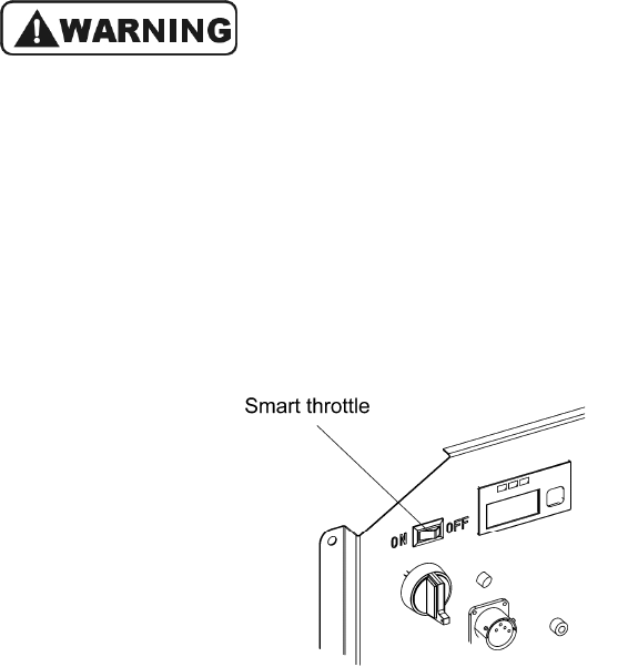
Smart throttle
Engine speed is kept at idle automatically when the electrical appliance is
disconnected and it returns to the proper speed to power of the electrical load when
electrical appliance is connected. This position is recommended to minimize the fuel
consumption while in operation.
Smart throttle system does not operate effectively, if the
electrical appliance requires big momentary electric
power.
When high electrical loads are connected simultaneously,
turn the Smart- throttle switch to the OFF position to
reduce voltage vibration.
OFF:
Smart-throttle system does not operate. Engine speed is kept at high-speed level.
(Figure 6))
Figure 6
8
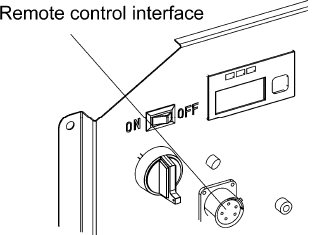
Remote control interface ((figure 7)
This interface can be connected with remote control box to realize wired remote start
and stop for the generator.
Figure 7 Remote control interface
9
3. PRE-OPERATION CHECK
Be sure to check the generator on a level surface with the
engine stopped.
3.1 Check the engine oil level.
Using nondetergent oil or 2-stroke engine oil could
shorten the engine's service life.
Use a high-detergent, premium quality 4-stroke engine oil,
certified to meet or exceed U.S. automobile
manufacture's requirements for API service classification
SG/SF.
Select the appropriate viscosity of oil according to the
ambient temperature.
SAE Viscosity Grades
Ambient temperature Engine oil type
-25℃ to -30℃ 10W-30
-15℃ to -40℃ 15W-40
Open the left side service door, loosen the dipstick, and wipe the dipstick with a clean
rag. Check the oil level by inserting the dipstick in the filler hole without screwing it in.
If the oil level is below the end of the dipstick, refill the recommended oil up to the top
of the oil filler neck. (See figure 4)
Figure 8 Oil level schematic diagram

10
Running the engine with insufficient oil can cause serious
engine damage.
The Low Oil Alarm System will automatically stop the
engine before the oil level falls below the safe limit.
However, to avoid the inconvenience of an unexpected
shutdown, it is still advisable to visually inspect the oil
level regularly.
3.2 Check the fuel level
Use automotive gasoline (Unleaded or lowleaded is preferred to minimize combustion
chamber deposits). If the fuel level is low, refuel the fuel tank until the level increased
to the specified mark. (See figure 9)
Never use an oil/gasoline mixture or dirty gasoline.
Avoid getting dirt, dust or water in the fuel tank.
After refueling, tighten the oil rule securely.
Gasoline is extremely flammable and is explosive under
certain conditions.
Refuel in a well-ventilated area with the engine stopped.
Do not smoke or allow flames or sparks in the area where
the engine is refueled or where gasoline is stored.
Do not overfill the fuel tank (there should be no fuel
above the upper limit mark). After refueling, make sure
the tank cap is closed properly and securely.
Be careful not to spill fuel when refueling. Spilled fuel or
fuel vapor may ignite, If any fuel is spilled, make sure the
area is dry before starting the engine.
Avoid repeated or prolonged contact with skin or
breathing of vapor. KEEP OUT OF REACH OF
CHILDREN.
Fuel capacity: 20L

11
Figure 9 Fuel level schematic diagram
Gasoline containing alcohol
If you decide to use a gasoline containing alcohol (gasohol), be sure it's octane rating
is at least as high as that recommended by us. There are two types of gasohol: one
containing ethanol, and the other containing methanol. Do not use gasohol that
contains more than 10% ethanol. Do not use gasoline containing methanol (methyl or
wood alcohol) that does not also contain cosolvents and corrosion inhibitors for
methanol. Never use gasoline containing more than 5% methanol, even if it has
cosolvents and corrosion inhibitors.
Fuel system damage or engine performance problems
resulting from the use of fuels that contain alcohol is not
covered under the warranty. We cannot endorse the use
of fuels containing methanol since evidence of their
suitability is as yet incomplete.
Before buying fuel from an unfamiliar station, try to find
out if the fuel contains alcohol, if it does, confirm the type
and percentage of alcohol used. If you notice any
undesirable operating symptoms while using a gasoline
that contains alcohol, or one that you think contains
alcohol, replace it by a gasoline that you know does not
contain alcohol.

12
3.3 Check the air filter.
Check the air filter element to be sure it is clean and in good condition.
Open the left side maintenance door, and remove the air filter cover, take out the
paper element and check it. Clean or replace the element if necessary. (See figure
10).
Never run the engine without the air filter. Rapid engine wear will result from
contaminants, such as dust and dirt, being drawn through the carburetor, into the
engine.
Figure 10 Air filter structure

13
4. STARTING THE ENGINE
1. Insert the engine key and turn the engine switch to “ON” position. (See figure 11).
Figure 11 Engine switch drawing
2. Turn the engine switch to “START” position until the engine is started. (See figure
12).
Figure 12 Engine switch

14
3. When the engine switch is in “OFF” position, the engine can be remote started by
remote controller.
Press the remote control button for two times, the engine will be started. (See figure
13).
Remote stop button
Remote start button
Figure 13 Remote controller
15
5. GENERATOR USE
To prevent electrical shock from faulty appliances, the
generator should be grounded. Connect a length of
heavy wire between the generator's ground terminal and
an external ground source.
Figure 14 Alternator ground schematic diagram
The starting power of most appliances exceeds the rated
power. So be sure the total starting wattage of all
appliances connected is less than the generator Max.
power.
For continuous running, the total wattage shall be within
the rated power specified in this manual.
Do not exceed the current limit specified for any one
receptacle.
Do not connect the generator to a household circuit. This
could cause the damage to the generator or to electrical
appliances in the house.
Do not modify or use the generator for other purpose
than it is intended for. Also observe the following when
using the generator.
●
Do not connect generators in parallel.
●
Do not connect an extension to the exhaust pipe.
When an extension cable is required, be sure to use a

16
rubber sheathed flexible cable (IEC 245 or equivalent).
Keep the generator away from other electric cables or
wires such as commercial power supply lines.
If you use AC receptacle at the same time, be sure not to
exceed the AC total power .
Electrical equipment (including lines and plug
connections) should not be defective.
5.1 AC applications
1. Start the engine and make sure the output indicator light (green) comes on.
2. Confirm the connected appliance is switched off, and insert the appliance plug to
the generator receptacle. (See figure 15)
Figure 15 Connection of appliance and generator
Be sure that all appliances are in good working order
before connecting them to the generator. If an appliance
begins to operate abnormally, becomes sluggish, or
stops suddenly, turn off the generator engine switch
immediately. Then disconnect the appliance, and
examine it for signs of malfunction.
Before connecting an appliance to the generator, check
that it is in good order, and that its electrical rating does
not exceed that of the generator. Then connect the power
cord of the appliance, and start the engine.

17
5.2 Display module
1. OIL ALARM/CHECK
(1
)
The function of oil alarm is to prevent generator damage from insufficient oil. The
indicator lamp will illumine when oil level is lower than safe value. At the same time,
the oil alarm auto stops the generator.
After put the engine switch to START position, if the engine doesn’t start or the oil
alarm indicator lamp lights, priority check if there is sufficient oil before check other
fault.
Figure 16
(2) If the oil alarm indicator lamp twinkle frequently, please contact Kipor dealer.
2. OUTPUT INDICATOR
The light of this output indicator (green) means the generator can work normally and
can provide power to receptacle.
Figure 17
3. OVERLOAD ALARM
The light of this indicator (red) means the generator is overload or short circuit or
overheat. After this indicator is lit, the generator will be disconnected with the
appliance within 5s, and the OUTPUT INDICATOR (green) will extinguish at the same
time.

18
Figure 18
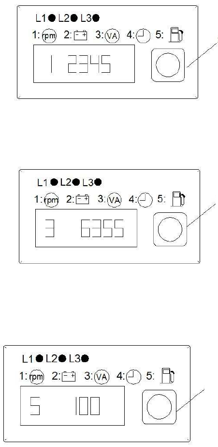
4. Display module
The display module shows engine speed, battery voltage, generator power, running
time, oil level and fault code for users. The user can press mode button to select
mode. Different mode provides the corresponding display.
When starting, the display module and three indicator lamps flash once at the same
time, and automatically check the operation conditions of the displayer and the three
indicator lamps.Once the engine runs, green output indicator lamp and display screen
light.
(1) Figure 19 is the display of running hrs. When the mode button selects mode 4, the
displayer shows generator running hrs.
Mode button
Figure 19
(2) Figure 20 is the display of generator power. When the mode button selects mode
3, the displayer shows generator power.
Mode button
19
Figure 20
(3) Figure 21 is the display of generator rotation speed. When mode button selects
mode 1, the displayer shows generator rotation speed.
Mode button
Figure 21
(4) Figure 22 is the display of battery voltage. When the mode button selects mode 2,
the displayer shows battery voltage.
Mode button
Figure 22
(5) Figure 23 is the display of oil level. When the mode button selects mode 5, the
displayer shows oil level percentage.
Mode button
Figure 23
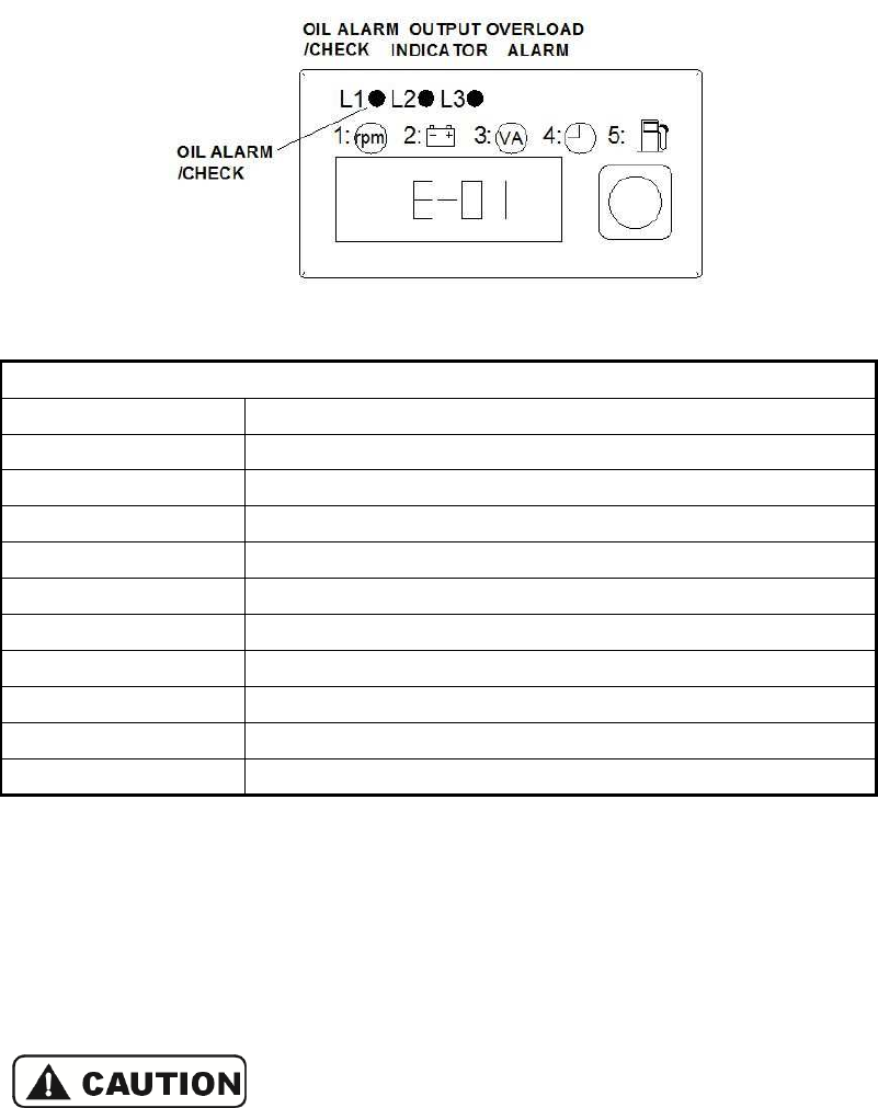
(6) Figure 24 is the system fault code display. When the generator appears system
fault, the displayer shows word like “E-01” (see figure 24). If the generator still run
20
after this system fault code is shown, the receptacle output may remain unchanged.
Beside, the remote operation gets well after system fault automatic cleaning. If the
system fault code can not automatically clean or the displayer shows other fault code,
please contact with Kipor dealer.
Figure 24
Meanings of fault codes
E-01 Engine under-speed protection
E-02 Engine over-speed protection
E-03 Inverter over-current protection
E-04 Inverter AC output over-voltage protection
E-05 Inverter over-heating protection
E-06 Inverter instantaneous over-current protection
E-07 Inverter DC component over-voltage protection
E-08 Inverter DC high voltage over-voltage protection
E-09 Inverter DC high voltage under-voltage protection
E-10 Communication error
E-99 02 sensor wire disconnected
5.3 Reset button
When overload indicator lamp lights, the generator will stop power output. At this time,
disconnect the load, check the load and the connection wire, after the failure resolved,
the user can press reset button in generator running status to extinguish the indicator
lamp. Let the generator continue to run and open the load again.
The red lamp and the green lamp may light at the same
time during the generator starting. It is normal If the red
lamp extinguishes in 4s. Otherwise, contact Kipor dealer.

6. STOPPING THE ENGINE
6.1 To stop the engine
in an emergency, turn the engine switch to the OFF position.
In normal use:
1.
Switch off the connected equipment and pull the inserted plug out.
2.
Turn the engine switch to the OFF position
6.2
If the generator is started by remote control, it can by
Note: if the generator is started when the engine switch is at “START” position, it
cannot be stopped by remote control.
Stop by remote control:
Shut off the connected appliance, press the stop button and the generator shall be
stopped.
The max. remote distance is 20m. See figure 2
Stop button
Figure 2
6.3
In condition that the generator cannot be stopped by remote control, turn the
engine switch to OFF1 position, then the remote control can emergency stop the
generator in remote start status. See figure 2
21
6. STOPPING THE ENGINE
in an emergency, turn the engine switch to the OFF position.
Switch off the connected equipment and pull the inserted plug out.
Turn the engine switch to the OFF position
If the generator is started by remote control, it can by
stopped by remote control.
Note: if the generator is started when the engine switch is at “START” position, it
cannot be stopped by remote control.
Shut off the connected appliance, press the stop button and the generator shall be
The max. remote distance is 20m. See figure 2
5.
Figure 2
5 Remote controller
In condition that the generator cannot be stopped by remote control, turn the
engine switch to OFF1 position, then the remote control can emergency stop the
generator in remote start status. See figure 2
6.
in an emergency, turn the engine switch to the OFF position.
stopped by remote control.
Note: if the generator is started when the engine switch is at “START” position, it
Shut off the connected appliance, press the stop button and the generator shall be
In condition that the generator cannot be stopped by remote control, turn the
engine switch to OFF1 position, then the remote control can emergency stop the

22
Figure 26 Remote stop in remote start status
7. MAINTENANCE
The purpose of the maintenance and adjustment schedule is to keep the generator in
the best operating condition.
Shut off the engine before performing any maintenance.
If the engine must be run, make sure the area is well
ventilated. The exhaust contains poisonous carbon
monoxide gas.
Use genuine our parts or their equivalent. The use of
replacement parts which are not of equivalent quality
may damage the generator.
7.1 Inspect or service as scheduled in the table below.
Items
Daily
First
month or
10hrs
Every 3
month or
50hrs
Every 6
month or
100hrs
Every
year or
300hrs
Interval(1)
Engine oil Check ○
Replace ○ ○
Air cleaner Check ○
Clean ○(2)
Spark plug Clean-adjust ○
Spark arrester Clean ○
Valve clearance Clean-adjust ○(3)
Fuel tank and filter Clean
○(3)
Oil pipe Check Every two years (replace if necessary(3))
Note:
The items marked by (1) means regular service interval.
The items marked by (2) shall be serviced more frequently when used in dusty
areas.
The items marked by (3) shall be serviced by authorized Kipor dealer, unless you
have proper tools and are mechanically proficient. Refer to the operation
manuals.

23
7.2 Replace engine oil
Rapidly and thoroughly drain off the engine oil when the engine is still hot. See figure
27.
Figure 27 Replace the engine oil
1. Open the left side service door.
2. Take out the oil dipstick.
3. Remove the oil drain bolt, discharge the oil and then tighten the bolt.
4. Add recommended oil the check the oil level.
5. Close the left side service door.
Oil capacity: 1.1L
In order to comply with the requirements of
environmental protection, we recommend that you put
the waste engine oil in sealed container and deliver it to
maintenance station or recycling center. Never pour the
oil on the ground or to the garbage.
7.3 Air filter service
A dirty air filter will restrict air flow to the engine. Please service the air filter regularly.
Service more frequently when operating the generator in extremely dirty areas.
Do not use gasoline or low flash point solvents for

24
cleaning. They are flammable and explosive under
certain conditions.
Never run the generator without the air filter, otherwise
rapid engine wear may result.
1. Open the left side service door.
2. Loosen the lock plate in top of air filter, and remove the air filter.
3. Foam filter element:
■
Dismantle the foam filter element from the air filter cover.
将
■
Wash the foam filter element with warm water mixed with household detergent and
then wash the element with clean water; you can also clean the element with
nonflammable detergent and dry the foam filter element in the air.
■
Wash the foam filter element with clean oil. Do remember to extrude the
redundant oil. Too much residual oil in the element will make the engine exhaust
black smoke in start process.
■
Reassemble the foam filter element to the air filter cover.
4. Paper filter element
Replace the dirty paper filter element with new one. Never clean the paper filter
element.
5. Reassemble the air filter cover.
6. Close the left side door.
7.4 SPARK PLUG SERVICE
RECOMMENTDED SPARK PLUG: WR7DC
To ensure proper engine operation, the spark plug must be properly gapped and free
of deposits.
1. Open the left side service door.
2. Remove the spark plug cap.
Spark plug wrench
Spark plug cover
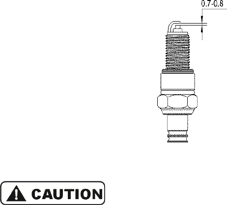
25
Figure 28 Dismantle the spark plug
3. Dismantle the spark plug using a spark plug wrench.
4. Clean any dirt from around the spark plug base.
5. Visually inspect the spark plug. Discard it if the insulator is cracked or chipped.
Clean the spark plug with a wire brush if it is to be reused.
6. Measure the plug gap with a feeler gauge.
The gap shall be 0.7~0.8mm (0.028-0.031in). Correct as necessary by carefully
bending the side electrode.
Figure 29 Measure the clearance of spark plug
The spark plug must be securely tightened. An
improperly tightened plug can become very hot and
possibly damage the generator.
Never use a spark plug with an improper heat range.
7. Install the spark plug carefully, by hand, to avoid cross-threading.
8. After a new spark plug has been seated by hand, it should be tightened 1/2 turn
with a wrench to compress its washer.
If a used plug is being re-installed, it should only require 1/8 to 1/4 turn after being
seated.
9. Re-install the spark plug cap on the spark plug securely.
10. Re-install the spark plug maintenance cover.

26
7.5 Spark arrester service (See figure 30)
Figure 30 Dismantle the spark arrester
The muffler is very hot after the generator is just stopped.
Service the generator when the muffler is cooled down.
In order to ensure the performance of spark arrester,
service the spark arrester once every 100hrs.
1. Remove the rear cover
2. Dismantle the spark arrester from the exhaust end.
3. Wipe off the carbon deposition with a carbon brush.
Check if there is any broken hole of crack on the arrester
net, replace the net as necessary.
4. Reassemble the spark arrester.
5. Reassemble the rear cover.

27
8. TRANSPORTING & STORAGE
8.1 Keep the generator far away from spill fuel in transportation, for oil mist or
spill fuel is very easy to burn.
8.2 Preparation for generator long term storage:
1. Be sure the storage area is free of excessive humidity and dust.
2. Drain off the fuel.
Figure 31 Drain the fuel
3. Charge the battery every two months.
4. Replace the engine oil.
5. Remove the spark plug and pour about a tablespoon of clean engine oil into the
cylinder. Crank the engine several revolutions to distribute the oil, and then re-install
the spark plug.

28
9. TROUBLE SHOOTING
When the engine does not start:
Be sure there is no spilled fuel around the spark plug, Spilled fuel may ignite.
Spark check:
1) Remove the spark plug cap and clean any dirt from around the spark plug.
2) Remove the spark plug and install the spark plug in the plug cap.
3) Set the plug side electrode on the cylinder head to ground. Keep the spark plug as
far as possible from the mounting hole.
4) Start the generator, sparks should jump across the gap.

29
Appliance does not operate:

30
10. SPECIFICATIONS
Genset model IG7000e
Rated frequency
(
Hz
)
60
Rated voltage
(
V
)
120/240
Rated current
(
A
)
45.8/22.9
Rated speed
(
r/min
)
3600
Rated output power
(
kVA
)
5.5
Max. output power
(
kVA
)
7.0
Engine
Engine model KG400GETi
Engine structure Single cylinder,4-stroke, air-cooled, OHV,
cylinder inclined arrangement,
Displacement
(
bore×stroke
)
398ml
(
89×64 mm
)
Compression ratio 8.5:1
Ignition system Transistor electrical ignition
Spark plug WR7DC
Start mode Electrical start
Fuel type Automotive unleaded gasoline
Oil type Above CD grade or SAE 10W-30, 15W-40
Capacity of fuel tank
(
L
)
20
Running lasting time
(
hrs
)(
under rated output
power
)
6.5
Fuel consumption
(
g/Kw.h
)
≤
480
Noise
(
d BA/at 7m
)(
0-load~full-load
)
65-75*
Dimension (L×W×H
)
[(mm)] 802×495×624
(
31.57×19.49×24.57
)
Net weight [kg] 90
(
198
)
*The declared values shall consider uncertainties due to production variation and
measurement procedures.

31
11. Electrical principle diagram
Figure 32 Electrical principle diagram

32
12. Trundle installation
Figure 36 Trundle installation drawing
1. Washer 2. Wheel 3. Lock pin
4. Locking swivel wheel 5. Bolt M6*16
To install the front wheels, install a washer on the axle, then the wheel, another
washer and secure with a wheel clip.
To install the locking swivel wheels, line up the bolt holes in the chassis with the holes
in the wheel attaching plate. Secure with the 4 bolts.
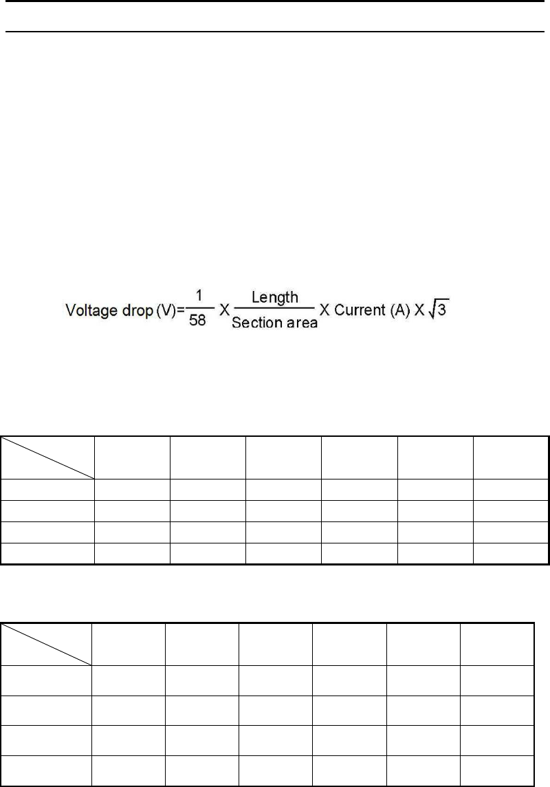
33
13. Appendix
1. Cable Selections
【
Note
】
Select the cable size based on the permissible current and distance between genset
and load.If the current going through the cable exceeds the permissible current, it
may burn the cables due to overheat. If the power cable is too long, and cable size is
too small, the resistance will be large and cause a voltage drop which may stop the
load from working.
●
Choose the cable length and section area within 5% rated voltage.
●
The following formula can be used to calculate the voltage drop value "e" from
cable length,sectional area and current in 3-phase 3-line situation.
The selection chart for single core and multi-core cables is as follows: (It’s applicable
for 220V voltage with a voltage drop of less than 10V).
For rubber insulated single core cable:
Length
Current
Within
50m 75m 100m 125m 150m 200m
50A 8 14 22 22 30 38
100A 22 30 38 50 50 60
200A 60 60 60 80 100 125
300A 100 100 100 125 150 200
For rubber insulated multi-core cable: mm
2
Length
Current
Within
50m 75m 100m 125m 150m 200m
50A 14 14 22 22 30 38
100A 38 38 38 50 50 60
200A 38×2 core 38×2 core 38×2 core 50×2 core 50×2 core 50×2 core
300A 60×2 core 60×2 core 60×2 core 60×2 core 80×2 core
100×2 core

34
2. Power Derating
Test conditions: Altitude: <=1000m Ambient temperature: 5
℃
~25
℃
Relative humidity: 30%
Power derating factor: C
(
Relative humidity:30%
)
Altitude
(
m
)
Ambient temperature
(
℃
)
25 30 35 40 45
1000 1 0.97 0.94 0.91 0.87
2000 0.87 0.84 0.81 0.78 0.74
3000 0.73 0.7 0.67 0.64 0.60
4000 0.60 0.57 0.54 0.51 0.47
Note:
The power derating factor is C-0.01 @ 60% relative humidity
The power derating factor is C-0.02 @ 80% relative humidity
The power derating factor is C-0.03 @ 90% relative humidity
The power derating factor is C-0.04 @ 100% relative humidity
For example:
The rated power of the genset is 20kW (PN) in test conditions. To determine the
power if the altitude is 2000 meters, the ambient temperature 40 and the relative
℃
humidity is 80%:
P=PN×(C-0.02)=20×(0.78-0.02)=15.2KW