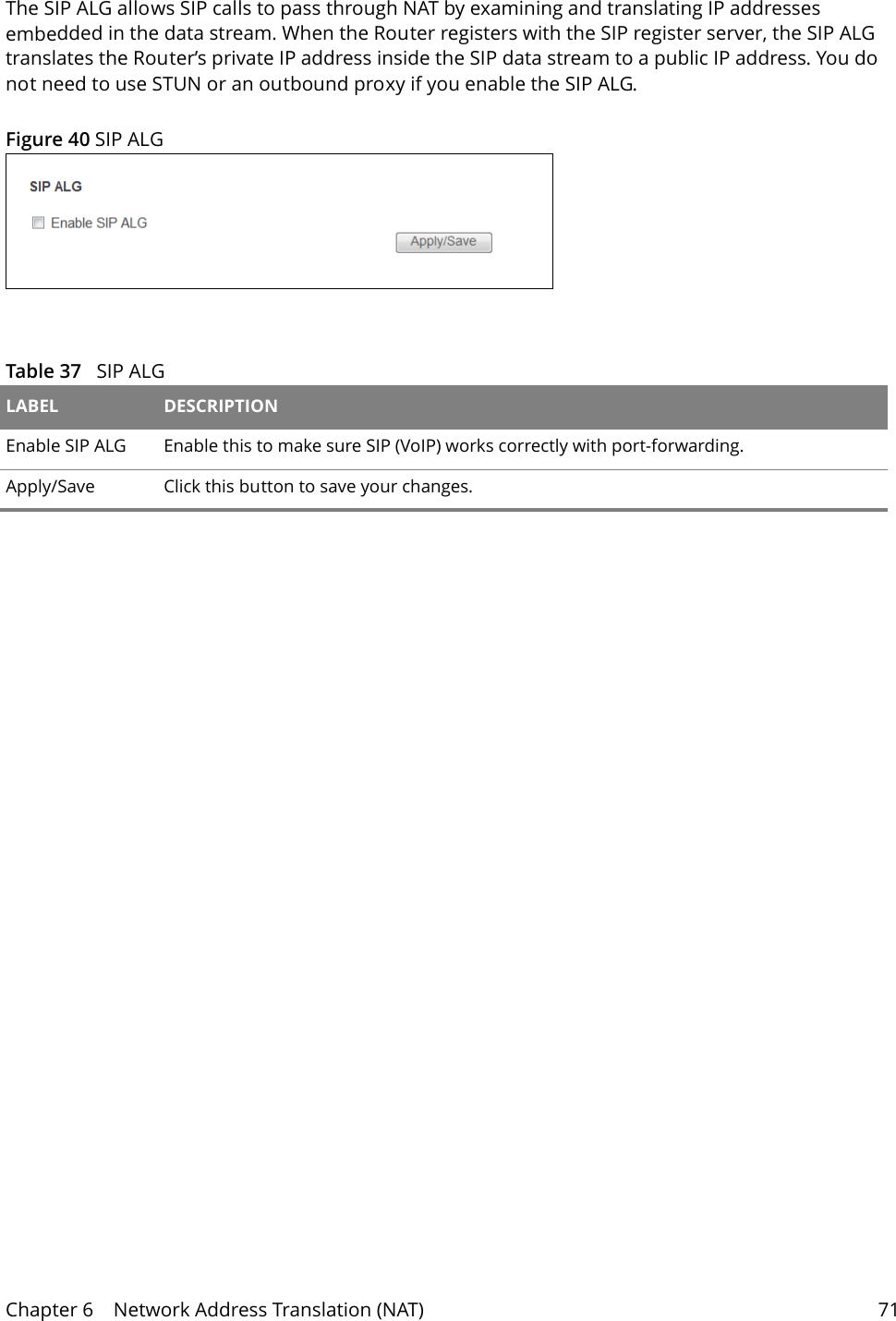
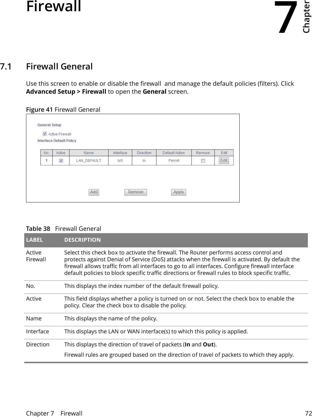
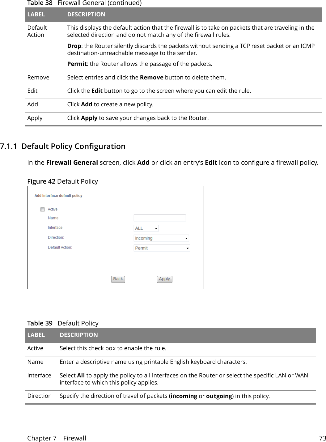
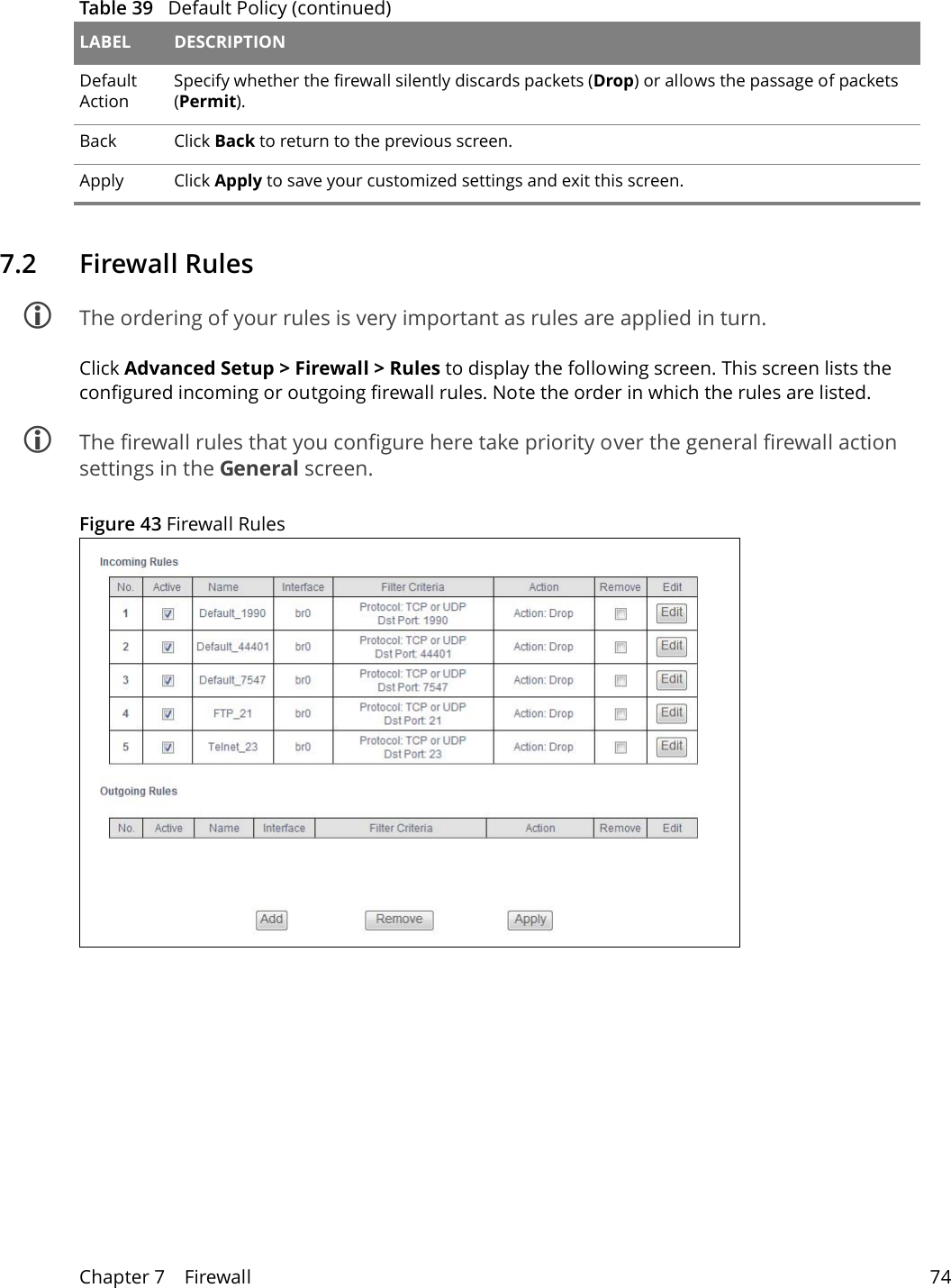
Wuxi MitraStar Technology GPT2541GNAC Equipo para acceso Fibra Optica User Manual
Wuxi MitraStar Technology Co.,Ltd Equipo para acceso Fibra Optica
UserManual.wiki
>
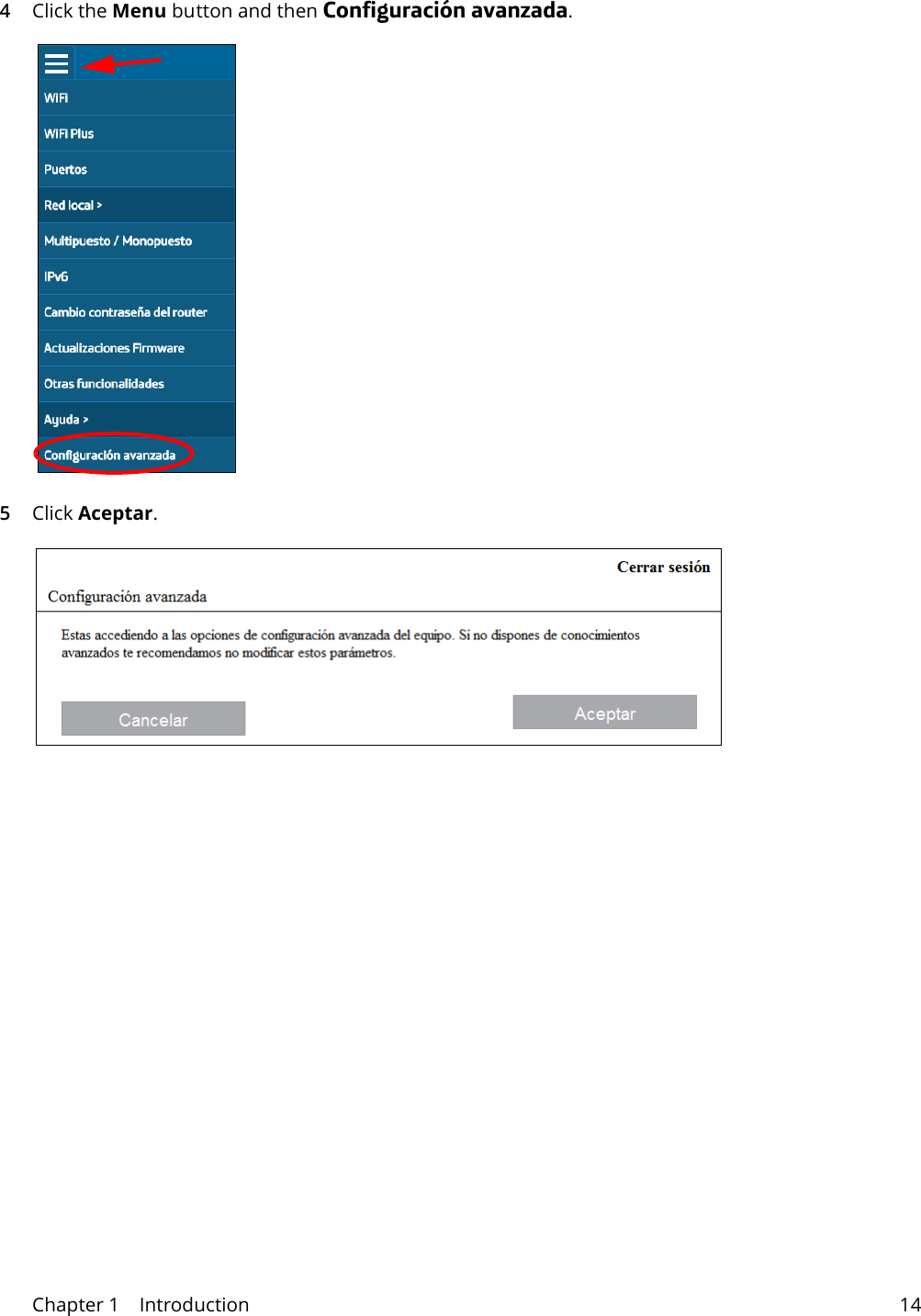
Wuxi MitraStar Technology
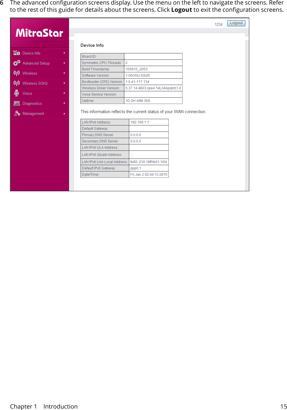
>
GPT2541GNAC User Manual
User Manual
Navigation menu
Upload a User Manual
Namespaces
Wiki Guide
HTML
PDF
Info
Views
User Manual
Discussion / Help
Navigation
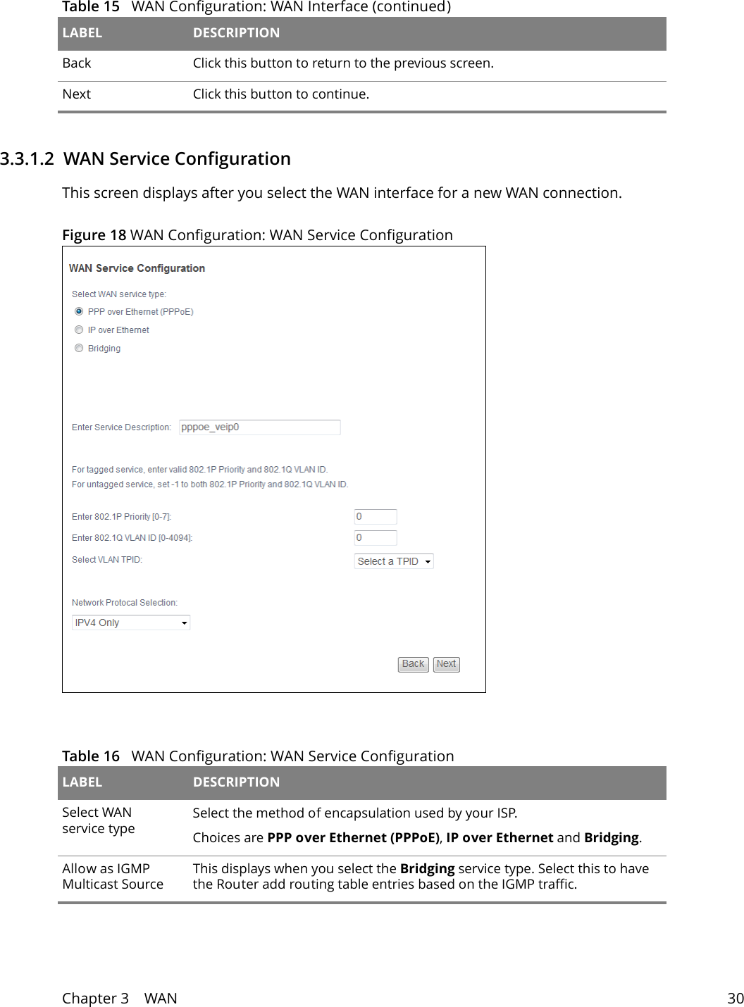
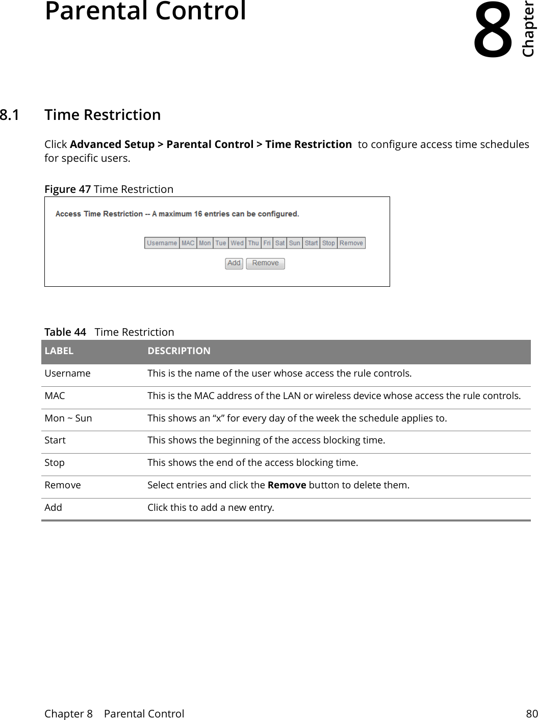
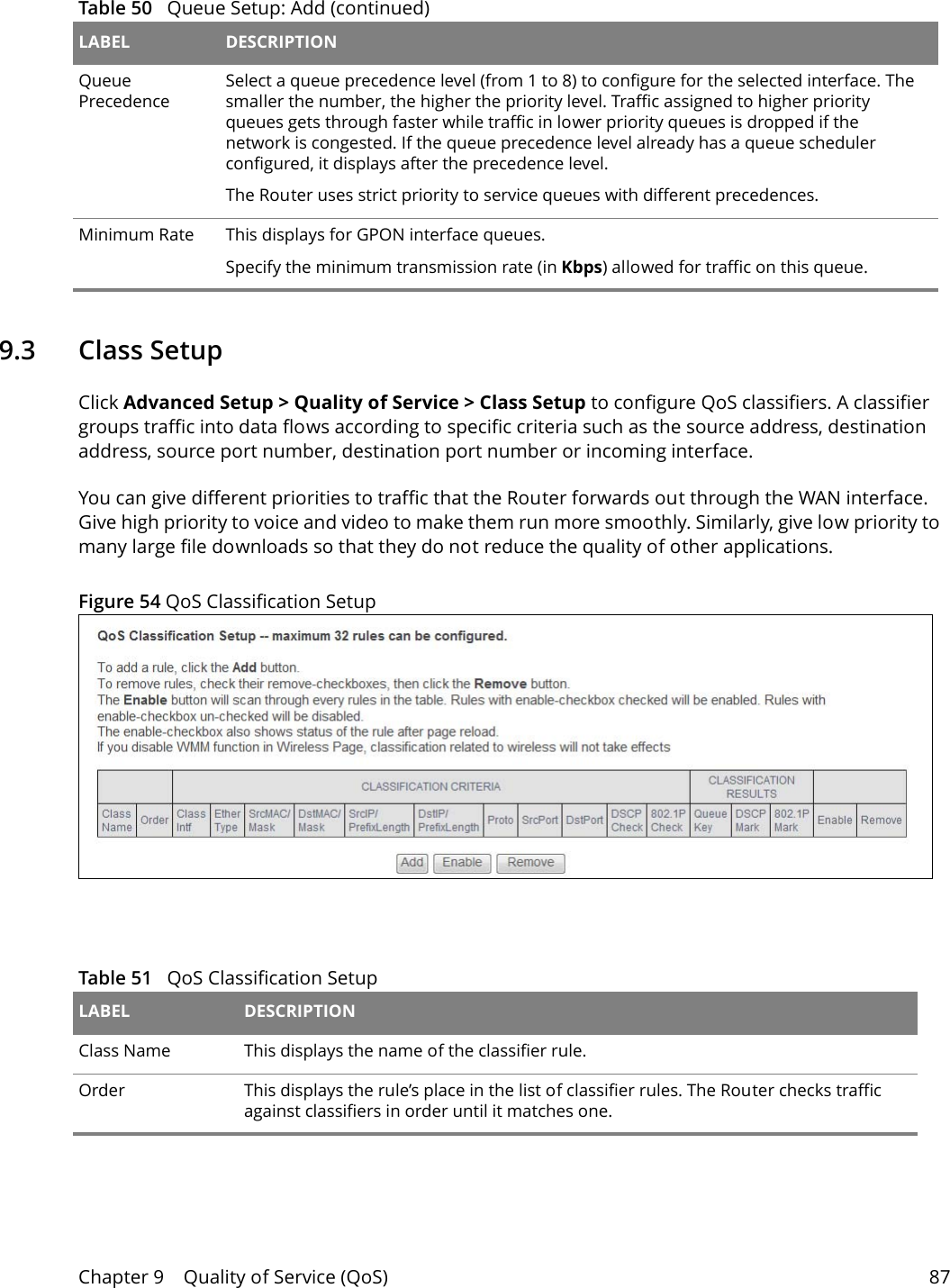
![Chapter 3 WAN 313.3.1.3 WAN IP Address and DNS ServerThe screen differs by the encapsulation you selected in the previous screen.Allow as MLD Multicast SourceThis displays when you select the Bridging service type. Select this to have the Router add routing table entries based on the MLD traffic.Enter Service DescriptionSpecify a name to identify the service. veip0 stands for a virtual Ethernet card and is the foundation for veip0/* which are virtual WAN interfaces of the physical GPON line. eth0 ~ eth3 represent the ethernet LAN ports 1 ~ 4. Enter 802.1P Priority [0-7]IEEE 802.1p defines up to 8 separate traffic types by inserting a tag into a MAC-layer frame that contains bits to define class of service. Type the IEEE 802.1p priority level (from 0 to 7) to add to traffic through this connection. The greater the number, the higher the priority level.Enter 802.1Q VLAN ID [0-4094]Type the VLAN ID number (from 1 to 4094) for traffic through this connection.Select VLAN TPID Select a Tag Protocol Identifier (TPID) the Router to add it to the service’s packets.Network Protocol SelectionSelect IPv4 Only to have the Router use only IPv4.Select IPv4&IPv6(Dual Stack) to let the Router connect to IPv4 and IPv6 networks an choose the protocol for applications according to the address type. This lets the Router use an IPv6 address when sending traffic through this connection. You can only select this for a WAN service that uses the PPPoE or IPoE encapsulation method over the layer 2 interface.Select IPv6 Only to have the Router use only IPv6.Back Click this button to return to the previous screen.Next Click this button to continue.Table 16 WAN Configuration: WAN Service ConfigurationLABEL DESCRIPTION](https://usermanual.wiki/Wuxi-MitraStar-Technology/GPT2541GNAC/User-Guide-3146865-Page-31.png)
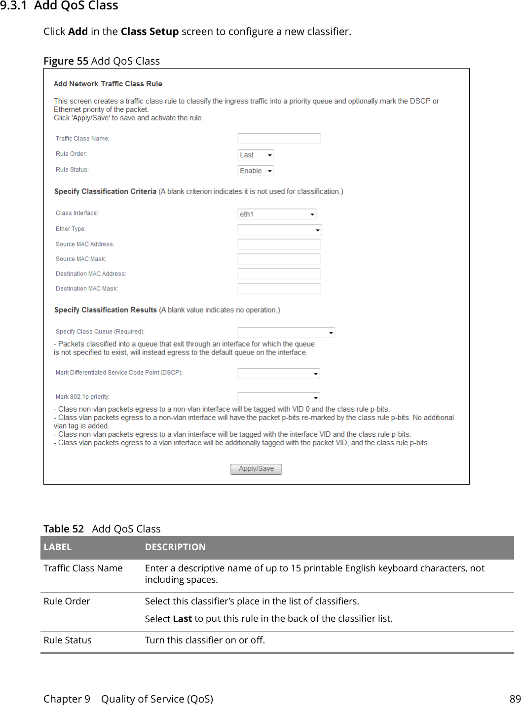
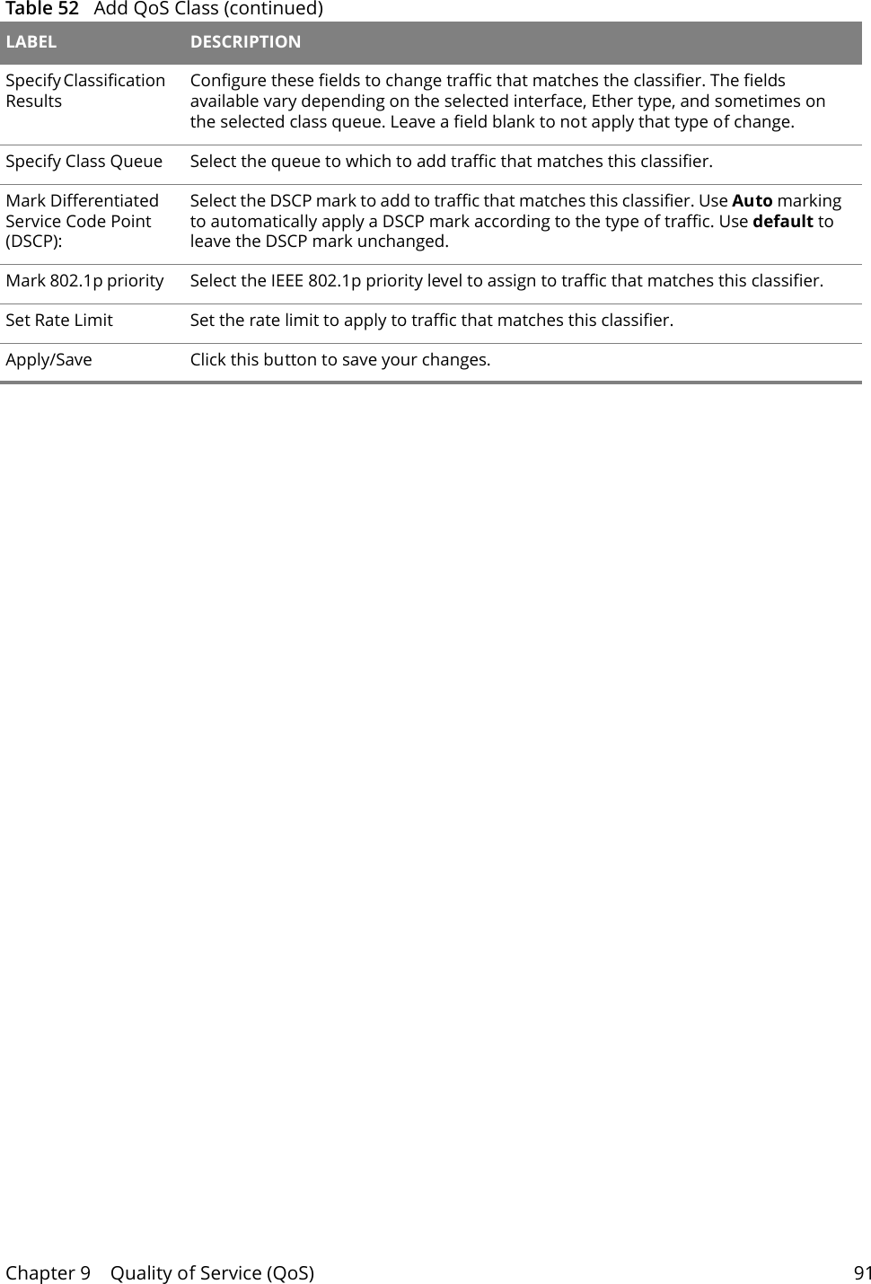
![Chapter 9 Quality of Service (QoS) 90Specify Classification Criteria Configure these fields to identify the traffic to which the class applies. The fields available vary depending on the selected interface and Ether type. Leave a field blank to not apply that criterion. Class Interface Select the ingress interface to which the classifier applies.Ether Type Select the predefined application (IP, ARP, IPv6, PPPoE discovery, PPPoE session, 8865, 8866, or IEEE 802.1q) to which the classifier applies. The list of types available to choose from varies depending on the selected interface. Source MAC Address Enter a MAC address to apply the classifier to packets from that MAC address.Source MAC Mask Type the mask for the specified MAC address to determine which bits a packet’s MAC address should match. Enter “f” for each bit of the specified source MAC address that the traffic’s MAC address should match. Enter “0” for the bit(s) of the matched traffic’s MAC address, which can be of any hexadecimal character(s). For example, if you set the MAC address to 00:13:49:00:00:00 and the mask to ff:ff:ff:00:00:00, a packet with a MAC address of 00:13:49:12:34:56 matches this criteria.Destination MAC AddressEnter a MAC address to apply the classifier to packets destined for that MAC address.Destination MAC MaskType the mask for the specified MAC address to determine which bits a packet’s MAC address should match. Enter “f” for each bit of the specified source MAC address that the traffic’s MAC address should match. Enter “0” for the bit(s) of the matched traffic’s MAC address, which can be of any hexadecimal character(s). For example, if you set the MAC address to 00:13:49:00:00:00 and the mask to ff:ff:ff:00:00:00, a packet with a MAC address of 00:13:49:12:34:56 matches this criteria.Source IP Address[/Mask]Select this and enter an IP address to apply the classifier to packets from that IP address. You can also include a source subnet mask.Vendor Class ID (DHCP Option 60)Select this and enter the Vendor Class Identifier (Option 60) of the matched traffic, such as the type of the hardware or firmware.User Class ID DHCP option 77Select this and enter a string that identifies the user’s category or application type in the matched DHCP packets.Destination IP Address[/Mask]Enter an IP address to apply the classifier to packets destined for that IP address. You can also include a destination subnet mask.Differentiated Service Code Point (DSCP) CheckSelect a DSCP mark of traffic to which to apply the classifier.802.1p Priority CheckThis field displays when you set the Ether Type field to 8021Q.Select the IEEE 802.1p priority level (between 0 and 7) of traffic to which to apply the classifier. "0" is the lowest priority level and "7" is the highest.Table 52 Add QoS Class (continued)LABEL DESCRIPTION](https://usermanual.wiki/Wuxi-MitraStar-Technology/GPT2541GNAC/User-Guide-3146865-Page-90.png)