Wuxi MitraStar Technology GPT2541GNAC Equipo para acceso Fibra Optica User Manual
Wuxi MitraStar Technology Co.,Ltd Equipo para acceso Fibra Optica
User Manual

Firmware Version 1.00
Edition 1, 9/2015
Default Login Details
http://192.168.1.1
User Name: admin
Password: 1234
GPT-2541GNAC
Indoor GPON HGU
User’s Guide
IMPORTANT!
READ CAREFULLY BEFORE USE.
KEEP THIS GUIDE FOR FUTURE REFERENCE.
Graphics in this book may differ slightly from the product due to differences in operating systems,
operating system versions, or if you installed updated firmware/software for your device. Every
effort has been made to ensure that the information in this manual is accurate.
Contents 3
Contents
8 Chapter 1: Introduction
8Overview
9 Hardware Connection
11 LEDs (Lights)
12 Advanced Configuration
16 Chapter 2: Device Info
16 Device Info Summary
18 WAN Info
19 LAN Statistics
21 WAN Statistics
22 Route Info
23 ARP Info
24 DHCP Leases
25 Chapter 3: WAN
25 GPON Layer2 Interface
26 Layer-2 GPON Interface Configuration
26 Ethernet Layer2 Interface
27 Ethernet Layer-2 Interface Configuration
27 WAN Service
29 WAN Connection Configuration
46 Chapter 4: LAN
46 LAN Setup
49 Add DHCP Static IP Lease
50 LAN Additional Subnet
51 LAN VLAN
53 IPv6 LAN Auto Configuration
56 Chapter 5: VPN
56 L2TP VPN Client
56 L2TP VPN Client: Add
62 Chapter 6: Network Address Translation (NAT)
62 Virtual Servers
63 Virtual Servers Add
Contents 4
65 Port Triggering
68 Add Port Triggering Rule
70 DMZ Host
70 SIP ALG
72 Chapter 7: Firewall
72 Firewall General
73 Default Policy Configuration
74 Firewall Rules
76 Firewall Rules Configuration
77 MAC Filtering
78 MAC Filtering Add
80 Chapter 8: Parental Control
80 Time Restriction
81 Add a Time Restriction Rule
82 URL Filter
83 Add a URL Filter Rule
84 Chapter 9: Quality of Service (QoS)
84 QoS General
85 Queue Setup
86 Add a QoS Queue
87 Class Setup
89 Add QoS Class
92 Chapter 10: Routing
92 Default Gateway
93 Static Route
94 Add Static Route
94 Policy Routing
96 Add Policy Routing
97 RIP
98 Chapter 11: DNS
98 DNS Server
100 Dynamic DNS
102 Dynamic DNS Add
103 Chapter 12: UPnP
103 UPnP
104 Chapter 13: DNS Proxy
Contents 5
104 DNS Proxy
105 Chapter 14: Interface Grouping
105 Interface Grouping
106 Interface Group Configuration
109 Chapter 15: IP Tunnel
109 IPv6inIPv4 (6RD)
110 IPv6inIPv4 Configuration
111 IPv4inIPv6 (Dual Stack Lite)
113 IPv4inIPv6 Configuration
114 Chapter 16: IPSec VPN
114 IPSec VPN
116 IPSec VPN Add Screen
121 Technical Reference
121 IPSec Architecture
122 Encapsulation
123 IKE Phases
124 Negotiation Mode
124 IPSec and NAT
125 VPN, NAT, and NAT Traversal
126 ID Type and Content
127 Pre-Shared Key
128 Diffie-Hellman (DH) Key Groups
129 Chapter 17: Certificates
129 Local Certificates
130 Create Certificate Request
132 Load Signed Certificate
132 Trusted CA
134 View Trusted CA Certificate
135 Import Trusted CA Certificate
136 Chapter 18: Power Management
136 Power Management
138 Chapter 19: Multicast
138 Multicast
140 Chapter 20: Wireless
140 Wireless Basic
143 Wireless Security
Contents 6
147 Wireless MAC Filter
148 Wireless MAC Filter Add
149 Wireless Advanced
152 Wireless Station Info
153 Wireless 5GHz Basic
156 Wireless 5GHz Advanced Screen
157 Wireless 5GHz WPS
159 Push Button Configuration
160 Wireless 5GHz MAC Filter
161 Wireless MAC Filter Add
162 Wireless 5GHz Bridge
163 Wireless 5GHz Station Info
165 Chapter 21: Voice
165 SIP Account
170 SIP Server
176 Dial Plan Rules
177 Phone Region
178 Call Rule
179 Call History Summary
180 Outgoing Calls
181 Incoming Calls
181 Technical Reference
190 Quality of Service (QoS)
191 Phone Services Overview
197 Chapter 22: Diagnostics
197 Diagnostics
198 Ping/TraceRoute/Nslookup
199 Chapter 23: Settings
199 Backup Configuration Using the Web Configurator
200 Restore Configuration Using the Web Configurator
201 Restoring Factory Defaults
202 Chapter 24: Logs
202 Logs
202 What You Need To Know
203 System Log
204 System Log Configuration
205 Security Log
207 Chapter 25: SNMP
Contents 7
207 SNMP Agent
210 Chapter 26: TR-069 Client
210 TR-069 Client
212 Chapter 27: Internet Time
212 Internet Time
214 Chapter 28: User Passwords
214 User Passwords
215 Chapter 29: GPON Password
215 GPON Password
216 Chapter 30: Update Software
216 Update Software
218 Chapter 31: Reboot
218 Restart Using the Web Configurator
219 Chapter 32: Troubleshooting
219 Overview
219 Power, Hardware Connections, and LEDs
220 Router Access and Login
221 Internet Access
222 Wireless Internet Access
223 Phone Calls and VoIP
224 UPnP
225 Appendix A: Safety Warnings
1
Chapter
Chapter 1 Introduction 8
CHAPTER 1
Chapter 1 Introduction
1.1 Overview
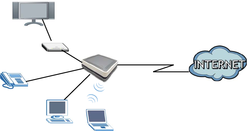
The GPT-2541GNAC GPON ONT combines high-speed Fiber Internet access with a built-in switch, a
firewall and high-speed wireless networking capability. It has a phone port for making calls over the
Internet (Voice over IP or VoIP). It also supports IPTV service when available from your service
provider.
The following figure shows an application example of the Router. The Router is connected to a
provides IPTV, VoIP services as well as wired and wireless Internet access to home devices on the
LAN.
Figure 1 Application Example
GPT-2541 GNAC
Set-Top Box
VoIP Phone
Chapter 1 Introduction 9
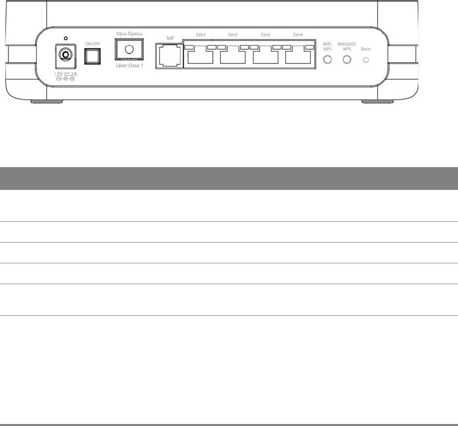
1.2 Hardware Connection
Make sure to use the proper cables and power adapter to connect the Router.
Figure 2 Rear Panel
The following table explains the connectors and buttons on the rear panel.
Table 1 Rear Panel
CONECTOR DESCRIPTION
12V-2A Connect the provided power adapter to the 12V-1A power connector. Attach the
power adapter to a proper power source.
ON/OFF Use this button to turn the Router on or off.
Fibra Óptica Connect the service provider’s fiber optic cable to this port.
Telf Use a telephone cable to connect the Router to a VoIP phone for VoIP service.
Eth 1-4 Use an Ethernet cable to connect a computer to one of these ports for initial
configuration and/or Internet access.
Wifi/WPS Use this button to enable or disable the 2.4 GHz WiFi and WPS features on the Router.
By default, WiFi is enabled on the Router. Press this button for 1 second to turn it off.
To enable the WPS feature, press the button for more than 3 seconds The WPS LED on
the front panel will flash green while the Router sets up a WPS Connection with the
wireless device.
Note: To activate WPS, you must enable WPS in the Router and in another wireless
device within two minutes of each other.

Chapter 1 Introduction 10
Wifi5GHz/WPS Use this button to enable or disable the 5 GHz WiFi and WPS features on the Router.
By default, WiFi is enabled on the Router. Press this button for 1 second to turn it off.
To enable the WPS feature, press the button for more than 3 seconds The WPS LED on
the front panel will flash green while the Router sets up a WPS Connection with the
wireless device.
Note: To activate WPS, you must enable WPS in the Router and in another wireless
device within two minutes of each other.
Reset Use this button to restore the default settings of the Router. Press this button for 10
seconds to restore default values. Press 1 second or longer to restart it.
Note: If you reset the Router, you will lose all configurations that you had previously
and the password will be reset to the defaults.
Table 1 Rear Panel (continued)
CONECTOR DESCRIPTION
Chapter 1 Introduction 11
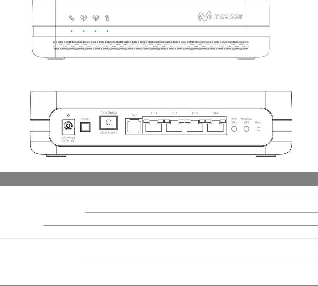
1.3 LEDs (Lights)
The following graphic displays the labels of the LEDs.
Figure 3 Front Panel LEDs
Figure 4 Rear Panel LEDs
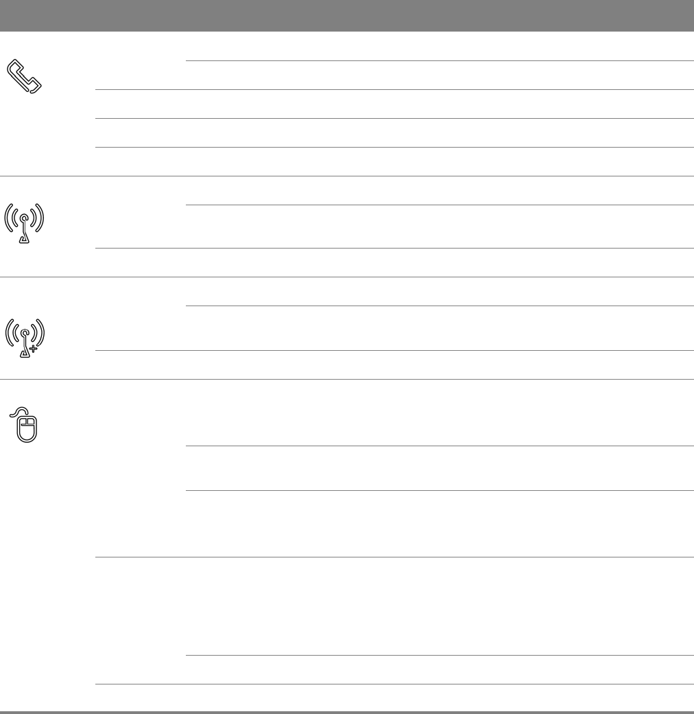
Table 2 LED Descriptions
LED COLOR STATUS DESCRIPTION
Power Blue On The Router is receiving power and ready for use.
Red On The Router has hardware failure.
Blinking The Router detected an error while self-testing.
Off The Router is not receiving power.
Eth 1-4 Blue On The Router has a successful Ethernet connection with a device on
the LAN.
Blinking The Router is sending or receiving data to/from the LAN.
Off The Router does not have an Ethernet connection with the LAN.
Chapter 1 Introduction 12
1.4 Advanced Configuration
Do the following to access the advanced configuration screens.
Telf Blue On The SIP registration is successful.
Blinking The Router is negotiating the SIP registration.
Green On There is incoming or outgoing voice traffic.
Red Blinking The Router has failed to register the VoIP service.
Off There is no VoIP service.
Wifi/WPS Blue On The 2.4 GHz wireless is on.
Blinking The 2.4 GHz WPS is activated. It also blinks when the Router is
setting up a WPS connection.
Off The 2.4 GHz wireless is not activated.
Wifi5GHz/
WPS
Blue On The 5 GHz wireless is on.
Blinking The 5 GHz WPS is activated. It also blinks when the Router is setting
up a WPS connection.
Off The 5 GHz wireless is not activated.
Internet Blue On The Router has a PPP connection but no traffic.
It has a WAN IP address (either static or assigned by a DHCP server),
PPP negotiation was successfully completed (if used).
Blinking Startup process. The Router is running an automatic startup
diagnostic process on the GPON port.
Fast Blinking The Router is sending or receiving IP traffic.
The Router is synchronizing with the PON. Activation phase. The
Router is negotiating a PPP connection.
Red On The Router attempted to make an IP connection but failed. Possible
causes are no response from a DHCP server, no PPPoE response,
PPPoE authentication failed.
The GPON port failed during the POST (Power On Self Test) or there
is an error due to hardware or firmware failure.
Blinking The GPON port’s optical power level is below the threshold.
Off There is no Internet connection.
Table 2 LED Descriptions (continued)
LED COLOR STATUS DESCRIPTION
Chapter 1 Introduction 13
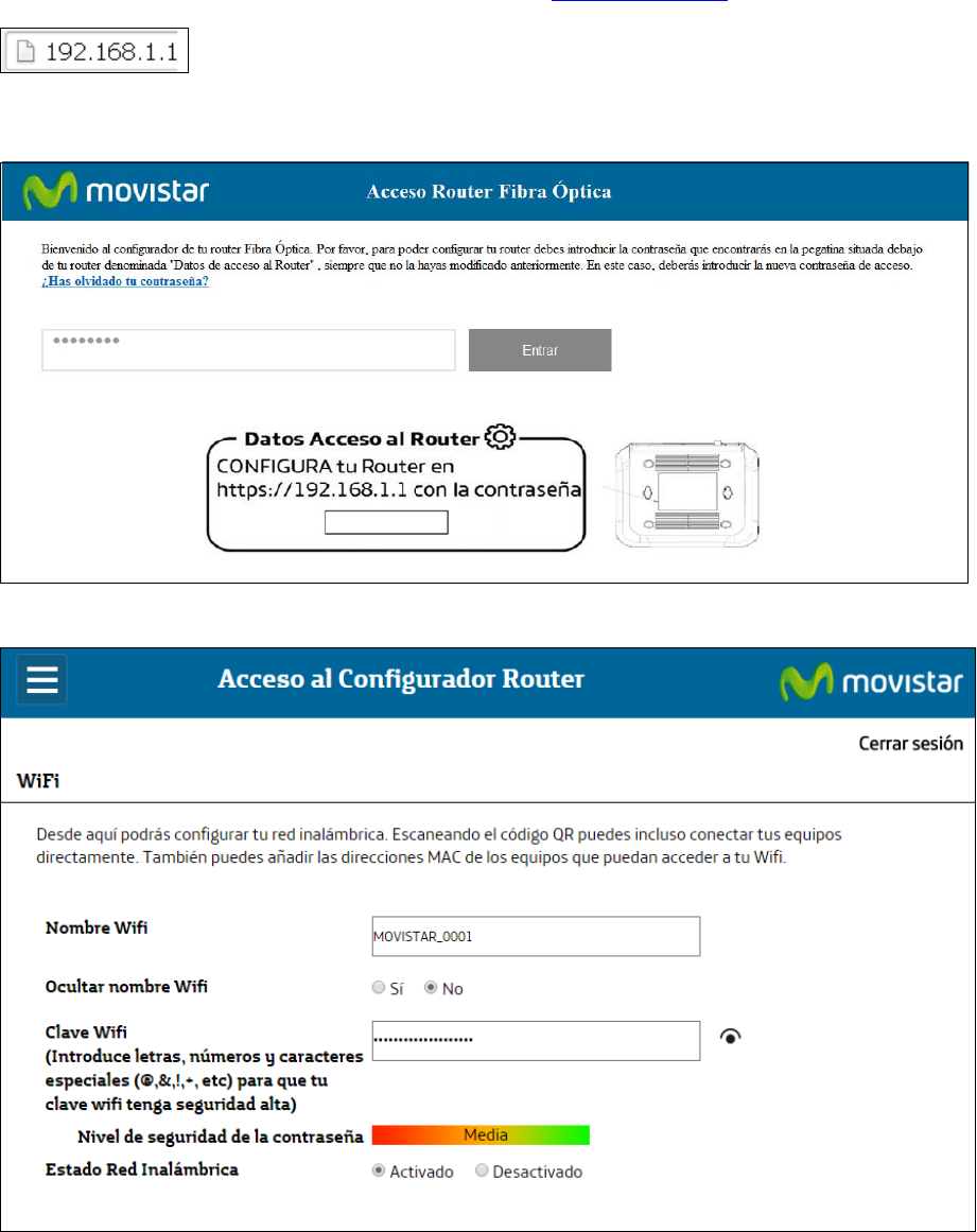
1Access the Client Wizard screens. Enter the IP address: http://192.168.1.1.
2The login screen appears. The default password is random. Please refer to the label sticker at the
bottom of the device. Enter the password. Click Entrar to enter the Client Wizard.
3The main screen appears.
Chapter 1 Introduction 14
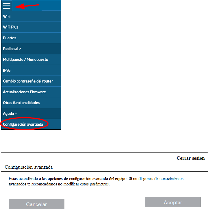
4Click the Menu button and then Configuración avanzada.
5Click Aceptar.
Chapter 1 Introduction 15
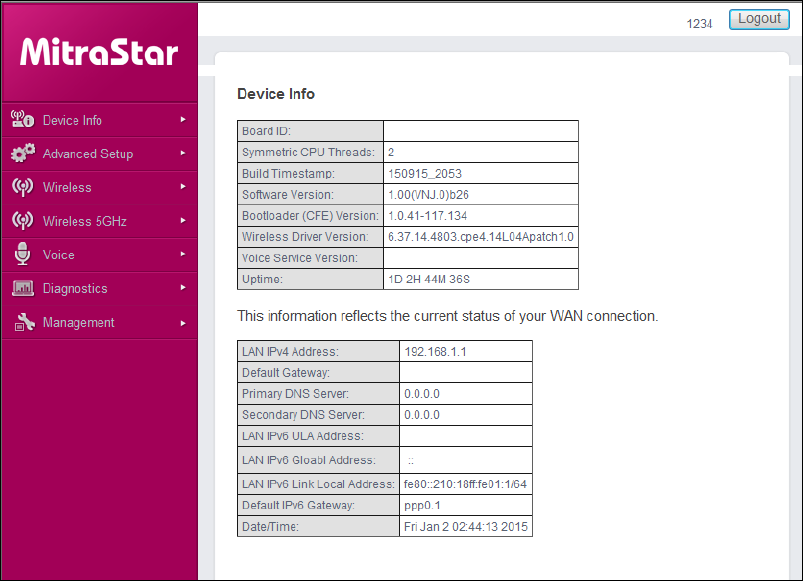
6The advanced configuration screens display. Use the menu on the left to navigate the screens. Refer
to the rest of this guide for details about the screens. Click Logout to exit the configuration screens.
2
Chapter
Chapter 2 Device Info 16
CHAPTER 2
Chapter 2 Device Info
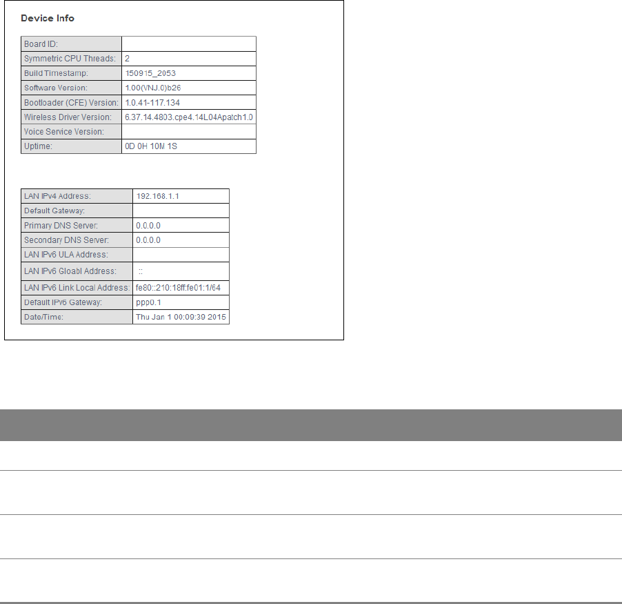
2.1 Device Info Summary
Click Device Info > Summary to open this screen with general device and WAN connection status
information.
Figure 5 Device Info Summary
Table 3 Device Info Summary
LABEL DESCRIPTION
Board ID This field displays the ID number of the circuit board in the Router.
Symmetric
CPU Threads
This field displays the number of threads in the Router’s CPU.
Build
Timestamp
This field displays the date (YYMMDD) and time (HHMM) of the firmware in the Router.
Software
Version
This field displays the current version of the firmware inside the Router.

Chapter 2 Device Info 17
Bootloader
(CFE) Version
This field displays the version of bootloader the Router is using.
Wireless
Driver Version
This field displays the version of the driver for the Router’s wireless chipset.
Voice Service
Version
This field displays the version of the VoIP software the Router is using.
Uptime This field displays how long the Router has been running since it last started up.
LAN IPv4
Address
This field displays the current IP address of the Router in the LAN.
Default
Gateway
This field displays the IP address of the gateway through which the Router sends traffic
unless it matches a static route.
Primary DNS
Server
The Router tries this DNS server first when it needs to resolve a domain name into a
numeric IP address.
Secondary
DNS Server
The Router uses this DNS server first when it needs to resolve a domain name into a
numeric IP address if the primary DNS server does not respond.
LAN IPv6 ULA
Address
This field displays the current unique local address (ULA). This is a unique IPv6 address
for use in private networks but not routable in the global IPv6 Internet.
LAN IPv6
Address
(Global)
This field displays the current global IPv6 address of the Router.
LAN IPv6 Link
Local Address
This field displays the current IPv6 address of the Router in the LAN.
Default IPv6
Gateway
This field displays the IPv6 address of the gateway through which the Router sends IPv6
traffic unless it matches a static route.
Date/Time This field displays the Router’s current day of the week, month, hour, minute, second,
and year.
Table 3 Device Info Summary (continued)
LABEL DESCRIPTION

Chapter 2 Device Info 18
2.2 WAN Info
Click Device Info > WAN to open this screen which lists the Router’s WAN connections and their
status.
Figure 6 WAN Info
Table 4 WAN Info
LABEL DESCRIPTION
Interface This shows the name of the WAN interface. veip0 stands for a virtual Ethernet card and
is the foundation for veip0/* which are virtual WAN interfaces of the physical GPON line.
The ppp0.* indicates a PPP connection.
The number after the dot (.) represents the VLAN ID number assigned to traffic sent
through this connection. The number after the underscore (_) represents the index
number of connections through the same interface.
(null) means the entry is not valid.
Description This is the service name of this connection.
Type This shows the method of encapsulation used by this connection (IP over Ethernet, PPP
over Ethernet, or bridging).
VlanMuxID This indicates the VLAN ID number assigned to traffic sent through this connection. This
displays N/A when there is no VLAN ID number assigned.
IPv6 This displays whether or not IPv6 is enabled on the interface.
Igmp Pxy This shows whether IGMP (Internet Group Multicast Protocol) proxy is activated or not
for this connection. IGMP is not available when the connection uses the bridging service.
Igmp Src Enbl This shows whether IGMP source enable is activated or not for this connection. IGMP
source enable has the Router add routing table entries based on the IGMP traffic.
MLD Pxy This shows whether Multicast Listener Discovery (MLD) proxy is activated or not for this
connection. MLD is not available when the connection uses the bridging service.
MLD Src Enbl This shows whether MLD source enable is activated or not for this connection. MLD
source enable has the Router add routing table entries based on the MLD traffic.
NAT This shows whether NAT is activated or not for this interface. NAT is not available when
the connection uses the bridging service.
Status This displays the connection state or Unconfigured if the interface has not yet been
configured.
Chapter 2 Device Info 19
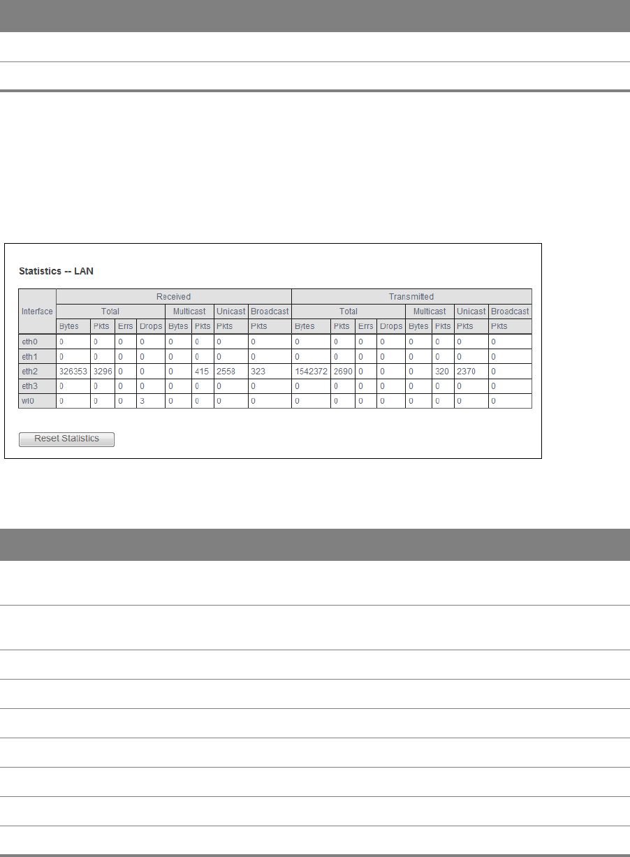
2.3 LAN Statistics
Click Device Info > Statistics > LAN to open this screen of traffic statistics counters for the Router’s
wired and wireless LAN interfaces. Use the button to clear the counters.
Figure 7 LAN Statistics
IPv4 Address This displays the interface’s current IPv4 address if it has one.
IPv6 Address This displays the interface’s current IPv6 address if it has one.
Table 4 WAN Info (continued)
LABEL DESCRIPTION
Table 5 LAN Statistics
LABEL DESCRIPTION
Interface These fields identify the LAN interfaces. eth0 ~ eth3 represent the ethernet LAN ports 1
~ 4. wlo represents the wireless LAN interface.
Received /
Transmitted
These fields display the number of bytes, packets, error packets, and dropped packets
for each interface.
Received
Bytes This indicates the number of bytes received on this interface.
Pkts This indicates the number of packets received on this interface.
Errs This indicates the number of frames with errors received on this interface.
Drops This indicates the number of received packets dropped on this interface.
Transmitted
Bytes This indicates the number of bytes transmitted on this interface.

Chapter 2 Device Info 20
Pkts This indicates the number of transmitted packets on this interface.
Errs This indicates the number of frames with errors transmitted on this interface.
Drops This indicates the number of outgoing packets dropped on this interface.
Reset
Statistics
Click this to clear the screen’s statistics counters.
Table 5 LAN Statistics (continued)
LABEL DESCRIPTION
Chapter 2 Device Info 21
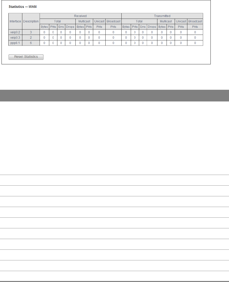
2.4 WAN Statistics
Click Device Info > Statistics > WAN Service to display the total, multicast, unicast, and broadcast
traffic statistics counters for the Router’s WAN interfaces. Use the button to clear the counters.
Figure 8 WAN Statistics
Table 6 WAN Statistics
LABEL DESCRIPTION
Interface This shows the name of the WAN interface used by this connection.
veip0 stands for a virtual Ethernet card and is the foundation for veip0/* which are
virtual WAN interfaces of the physical GPON line. The ppp0.* indicates a PPP
connection.
eth0 ~ eth3 represent the Ethernet LAN ports 1 ~ 4 and are the foundation for eth0/*
which are virtual WAN interfaces of the physical Gigabit Ethernet line.
The number after the dot (.) represents the VLAN ID number assigned to traffic sent
through this connection. The number after the underscore (_) represents the index
number of connections through the same interface.
(null) means the entry is not valid.
Description This is the service name of this connection.
Received
Bytes This indicates the number of bytes received on this interface.
Pkts This indicates the number of packets received on this interface.
Errs This indicates the number of frames with errors received on this interface.
Drops This indicates the number of received packets dropped on this interface.
Transmitted
Bytes This indicates the number of bytes transmitted on this interface.
Pkts This indicates the number of transmitted packets on this interface.
Errs This indicates the number of frames with errors transmitted on this interface.

Chapter 2 Device Info 22
2.5 Route Info
Click Device Info > Route to display the Router’s IPv4 and IPv6 routing tables.
Figure 9 Route Info
Table 7 Route Info
LABEL DESCRIPTION
Destination This displays the IP address to which this entry applies.
Gateway This displays the gateway the Router uses to send traffic to the entry’s destination
address.
Subnet Mask This displays the subnet mask of the destination net.
Flag This displays whether the route is up (U), the Router drops packets for this destination
(!), the route uses a gateway (G), the target is in the neighbor cache (C), the target is a
host (H), reinstate route for dynamic routing (R), the route was dynamically installed by
redirect (D), or modified from redirect (M).
Metric The metric represents the “cost” of transmission for routing purposes. IP routing uses
hop count as the measurement of cost, with a minimum of 1 for directly-connected
networks.
Service The name of a specific service to which the route applies if one is specified.
Interface The interface through which this route sends traffic.
Drops This indicates the number of outgoing packets dropped on this interface.
Reset Click this to clear the screen’s statistics counters.
Table 6 WAN Statistics (continued)
LABEL DESCRIPTION

Chapter 2 Device Info 23
2.6 ARP Info
Click Device Info > ARP to display the Router’s IPv4 Address Resolution Protocol and IPv6 neighbor
tables. This screen lists the IP addresses the Router has mapped to MAC addresses.
Figure 10 ARP Info
Table 8 ARP Info
LABEL DESCRIPTION
IPv4 / IPv6
address
The learned IP address of a device connected to one of the system’s ports.
Flags Static - static entry, Dynamic - dynamic entry that is not yet complete, Complete -
dynamic entry that is complete.
HW Address The MAC address of the device with the listed IP address.
Device The interface through which the Router sends traffic to the device listed in the entry.
Chapter 2 Device Info 24
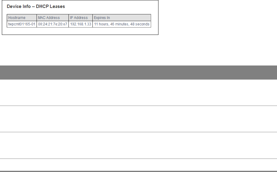
2.7 DHCP Leases
Click Device Info > DHCP to display the Router’s list of IP address currently leased to DHCP clients.
Figure 11 DHCP Leases
Table 9 DHCP Leases
LABEL DESCRIPTION
Hostname This field displays the name used to identify this device on the network (the computer
name). The Router learns these from the DHCP client requests. “None” shows here for a
static DHCP entry.
MAC Address This field displays the MAC address to which the IP address is currently assigned or for
which the IP address is reserved. Click the column’s heading cell to sort the table entries
by MAC address. Click the heading cell again to reverse the sort order.
IP Address This field displays the IP address currently assigned to a DHCP client or reserved for a
specific MAC address. Click the column’s heading cell to sort the table entries by IP
address. Click the heading cell again to reverse the sort order.
Expires In This field displays how much longer the IP address is leased to the DHCP client.

3
Chapter
Chapter 3 WAN 25
CHAPTER 3
Chapter 3 WAN
3.1 GPON Layer2 Interface
The Router must have a layer-2 interface to allow users to use the GPON port to access the Internet.
Log into the Router’s Web Configurator and click Advanced Setup > Layer2 Interface > GPON
Interface to manage the GPON layer-2 interface.
The GPON and ETH layer-2 interfaces cannot work at the same time.
Figure 12 GPON Interface
The following table describes the fields in this screen.
Table 10 GPON Interface
LABEL DESCRIPTION
Interface/(Name) The name of a configured layer-2 interface. veip0 stands for a virtual Ethernet card
and is the foundation for veip0/* which are virtual WAN interfaces of the physical
GPON line.
The number after the dot (.) represents the VLAN ID number assigned to traffic sent
through this connection. The number after the underscore (_) represents the index
number of connections through the same interface.
Connection Mode This shows the connection mode of the layer-2 interface.
Remove Select an interface and click the Remove button to delete it. You cannot remove a
layer-2 interface when a WAN service is associated with it.
Add Click this button to create a new layer-2 interface. You can only have one GPON layer
2 interface at a time.
Chapter 3 WAN 26
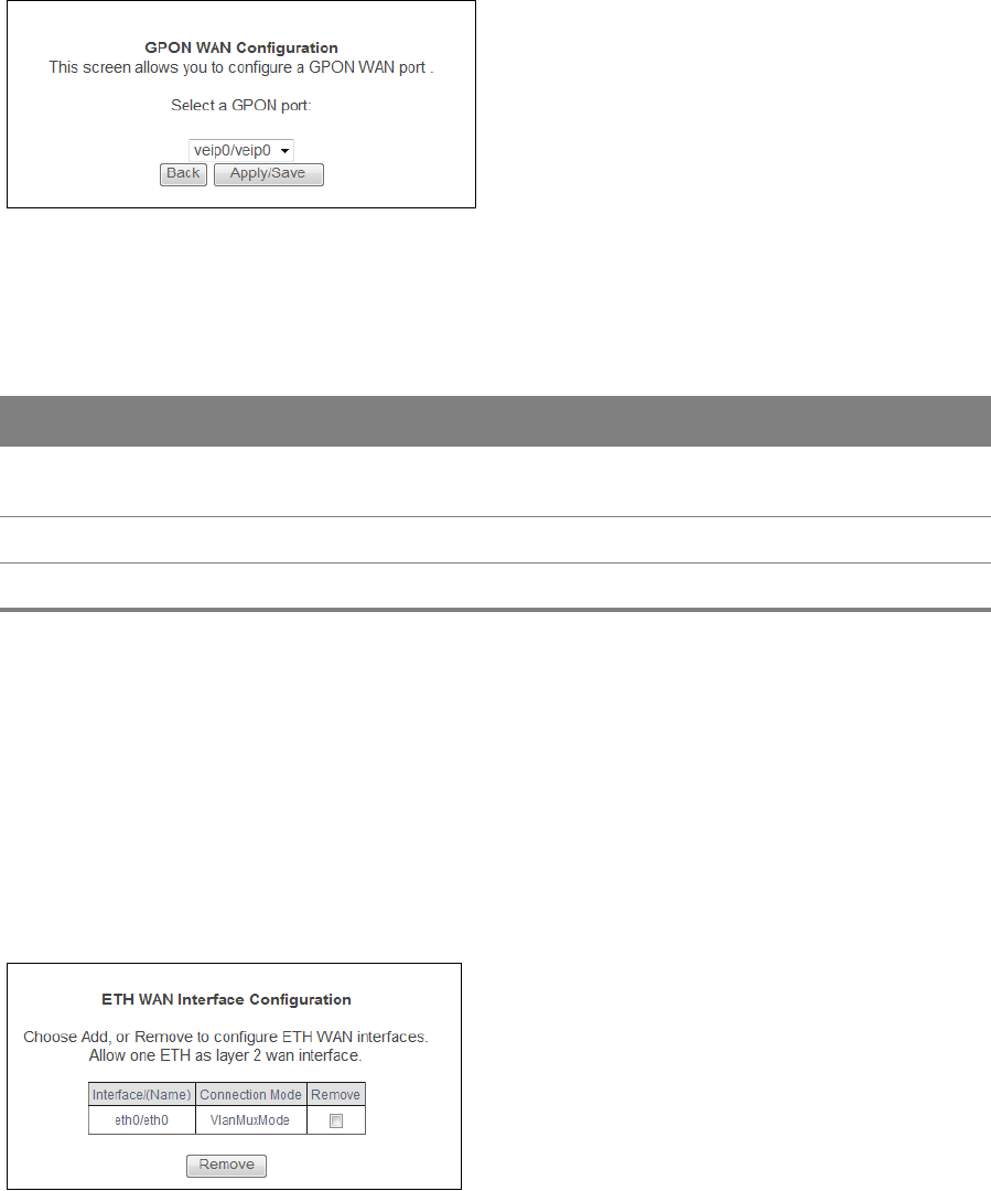
3.1.1 Layer-2 GPON Interface Configuration
Click the Add button in the Layer2 Interface: GPON Interface screen to open the following screen.
Use this screen to create a new layer-2 interface.
Figure 13 GPON Interface Configuration
Select the GPON port and click Apply/Save.
The following table describes the fields in this screen.
Table 11 GPON Interface Configuration
LABEL DESCRIPTION
Select a GPON
port
Select a GPON port. veip0 stands for a virtual Ethernet card and is the foundation
for veip0/* which are virtual WAN interfaces of the physical GPON line.
Back Click this button to return to the previous screen without saving any changes.
Apply/Save Click this button to save your changes and go back to the previous screen.
3.2 Ethernet Layer2 Interface
The Router must have a layer-2 interface to allow users to use the Gigabit Ethernet port to access
the Internet. Log into the Router’s Web Configurator and click Advanced Setup > Layer2 Interface
> ETH Interface to manage the Ethernet layer-2 interface.
The GPON and ETH layer-2 interfaces cannot work at the same time.
Figure 14 ETH Interface
Chapter 3 WAN 27
The following table describes the fields in this screen.
Table 12 ETH Interface
LABEL DESCRIPTION
Interface/(Name) The name of a configured layer-2 interface. eth0 ~ eth3 represent the ethernet LAN
ports 1 ~ 4.
Connection Mode This shows the connection mode of the layer-2 interface.
Remove Select an interface and click the Remove button to delete it. You cannot remove a
layer-2 interface when a WAN service is associated with it.
Add Click this button to create a new layer-2 interface. You can only have one ETH layer 2
interface at a time.
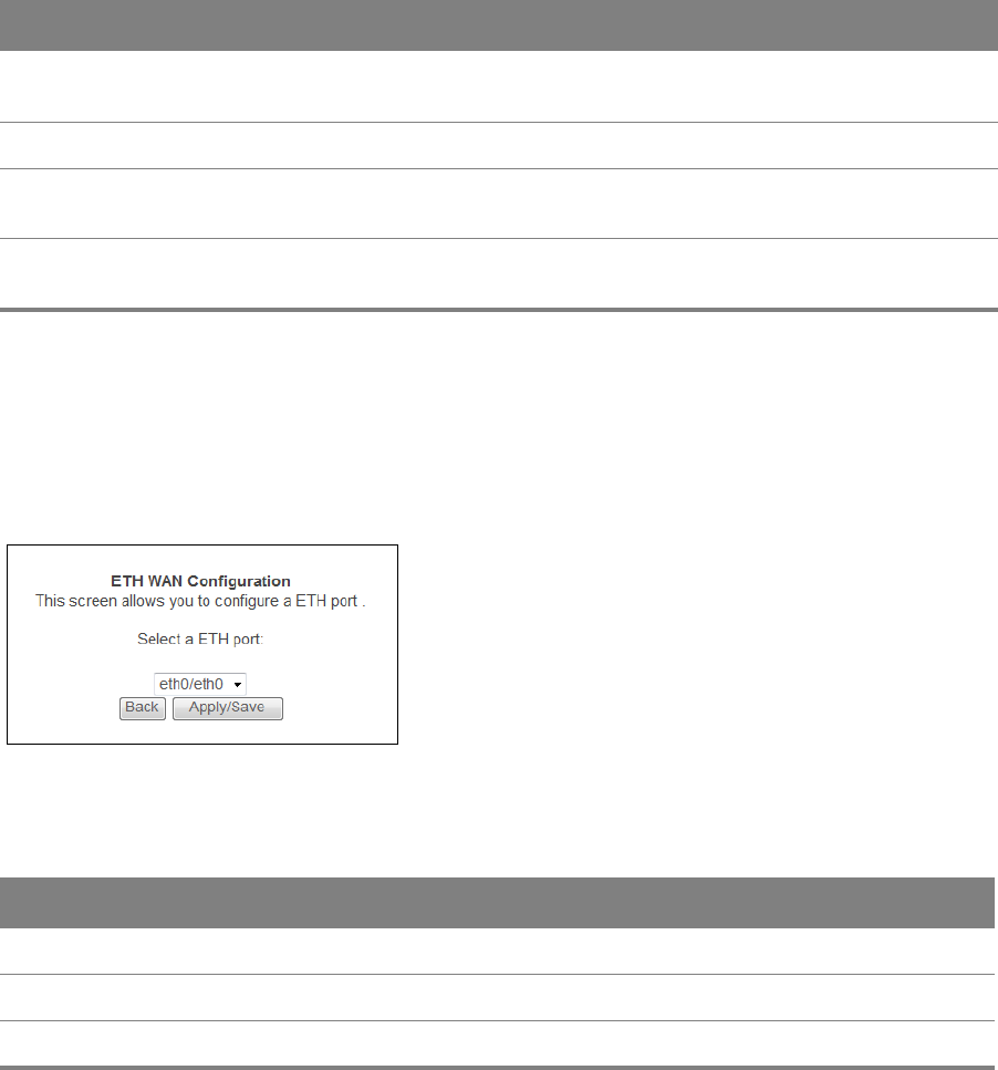
3.2.1 Ethernet Layer-2 Interface Configuration
Click the Add button in the Layer2 Interface: ETH Interface screen to open the following screen.
Use this screen to create a new layer-2 interface.
Figure 15 ETH Interface Configuration
The following table describes the fields in this screen.
Table 13 ETH Interface Configuration
LABEL DESCRIPTION
Select a ETH port Select an Ethernet port. eth0 ~ eth3 represent the ethernet LAN ports 1 ~ 4.
Back Click this button to return to the previous screen without saving any changes.
Apply/Save Click this button to save your changes and go back to the previous screen.
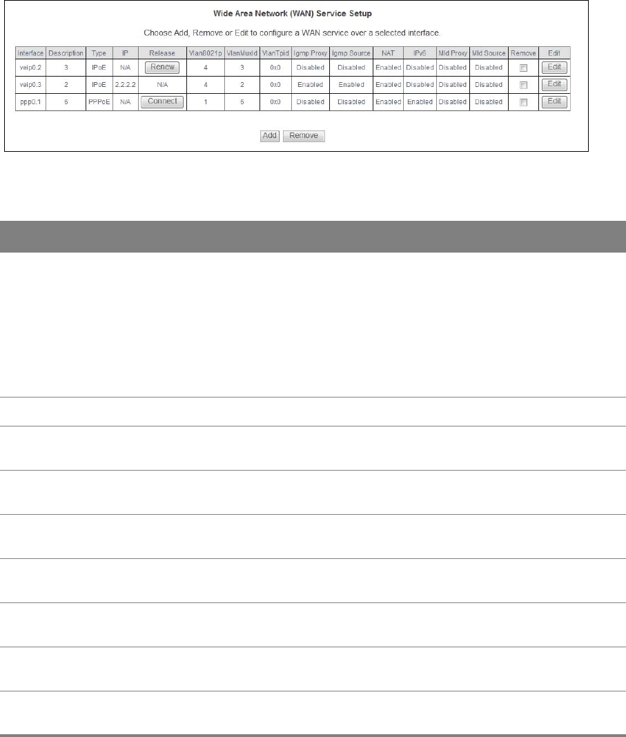
3.3 WAN Service
Use this screen to change your Router’s WAN settings. Click Advanced Setup > WAN Service. The
summary table shows you the configured WAN services (connections) on the Router.
Chapter 3 WAN 28
To use NAT, firewall or IGMP proxy in the Router, you need to configure a WAN connection with
PPPoE or IPoE.
When a layer-2 interface is in VLAN MUX Mode, you can configure up to five WAN services
on the Router.
Figure 16 WAN Service
Table 14 WAN Service
LABEL DESCRIPTION
Interface This shows the name of the interface used by this connection.
veip0 stands for a virtual Ethernet card and is the foundation for veip0/* which are virtual
WAN interfaces of the physical GPON line. The ppp0.* indicates a PPP connection.
The number after the dot (.) represents the VLAN ID number assigned to traffic sent
through this connection. The number after the underscore (_) represents the index number
of connections through the same interface.
(null) means the entry is not valid.
Description This is the service name of this connection.
Type This shows the method of encapsulation used by this connection (IP over Ethernet, PPP
over Ethernet, or bridging).
IP This displays the IP address the connection uses. This displays N/A when the connection
does not have an IP address.
Release Use the buttons in this column to renew, release, or connect a WAN connection. This
displays N/A for a connection with a static IP address.
Vlan8021p This indicates the 802.1P priority level assigned to traffic sent through this connection. This
displays N/A when there is no priority level assigned.
VlanMuxId This indicates the VLAN ID number assigned to traffic sent through this connection. This
displays N/A when there is no VLAN ID number assigned.
VlanTpid This field displays the VLAN Tag Protocol Identifier (TPID), a four-digit hexadecimal number
from 0000 to FFFF that the OLT adds to the matched packets.
Igmp Proxy This shows whether IGMP (Internet Group Multicast Protocol) proxy is activated or not for
this connection. IGMP is not available when the connection uses the bridging service.

Chapter 3 WAN 29
3.3.1 WAN Connection Configuration
Click the Edit or Add button in the WAN Service screen to configure a WAN connection.
3.3.1.1 WAN Interface
This screen displays when you add a new WAN connection.
Figure 17 WAN Configuration: WAN Interface
NAT This shows whether NAT is activated or not for this interface. NAT is not available when the
connection uses the bridging service.
IPv6 This shows whether IPv6 is activated or not for this connection. IPv6 is not available when
the connection uses the bridging service.
Mld Proxy This shows whether Multicast Listener Discovery (MLD) proxy is activated or not for this
connection. MLD is not available when the connection uses the bridging service.
MLD Source This shows whether MLD source is activated or not for this connection.
Remove Select an interface and click the Remove button to delete it. You cannot remove a layer-2
interface when a WAN service is associated with it.
Edit Click the Edit button to configure the WAN connection.
Click the Remove icon to delete the WAN connection.
Add Click Add to create a new connection.
Table 14 WAN Service (continued)
LABEL DESCRIPTION
Table 15 WAN Configuration: WAN Interface
LABEL DESCRIPTION
Select a layer 2
interface for this
service
Select the port this WAN service uses for data transmission.
veip0/veip0 is the GPON port.
eth0 ~ eth3 represent the ethernet LAN ports 1 ~ 4.
Chapter 3 WAN 30
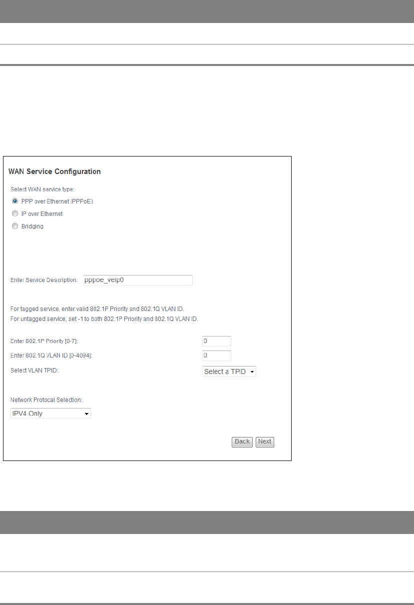
3.3.1.2 WAN Service Configuration
This screen displays after you select the WAN interface for a new WAN connection.
Figure 18 WAN Configuration: WAN Service Configuration
Back Click this button to return to the previous screen.
Next Click this button to continue.
Table 15 WAN Configuration: WAN Interface (continued)
LABEL DESCRIPTION
Table 16 WAN Configuration: WAN Service Configuration
LABEL DESCRIPTION
Select WAN
service type
Select the method of encapsulation used by your ISP.
Choices are PPP over Ethernet (PPPoE), IP over Ethernet and Bridging.
Allow as IGMP
Multicast Source
This displays when you select the Bridging service type. Select this to have
the Router add routing table entries based on the IGMP traffic.

Chapter 3 WAN 31
3.3.1.3 WAN IP Address and DNS Server
The screen differs by the encapsulation you selected in the previous screen.
Allow as MLD
Multicast Source
This displays when you select the Bridging service type. Select this to have
the Router add routing table entries based on the MLD traffic.
Enter Service
Description
Specify a name to identify the service.
veip0 stands for a virtual Ethernet card and is the foundation for veip0/*
which are virtual WAN interfaces of the physical GPON line.
eth0 ~ eth3 represent the ethernet LAN ports 1 ~ 4.
Enter 802.1P
Priority [0-7]
IEEE 802.1p defines up to 8 separate traffic types by inserting a tag into a
MAC-layer frame that contains bits to define class of service.
Type the IEEE 802.1p priority level (from 0 to 7) to add to traffic through this
connection. The greater the number, the higher the priority level.
Enter 802.1Q
VLAN ID [0-4094]
Type the VLAN ID number (from 1 to 4094) for traffic through this
connection.
Select VLAN TPID Select a Tag Protocol Identifier (TPID) the Router to add it to the service’s
packets.
Network Protocol
Selection
Select IPv4 Only to have the Router use only IPv4.
Select IPv4&IPv6(Dual Stack) to let the Router connect to IPv4 and IPv6
networks an choose the protocol for applications according to the address
type. This lets the Router use an IPv6 address when sending traffic through
this connection. You can only select this for a WAN service that uses the
PPPoE or IPoE encapsulation method over the layer 2 interface.
Select IPv6 Only to have the Router use only IPv6.
Back Click this button to return to the previous screen.
Next Click this button to continue.
Table 16 WAN Configuration: WAN Service Configuration
LABEL DESCRIPTION
Chapter 3 WAN 32
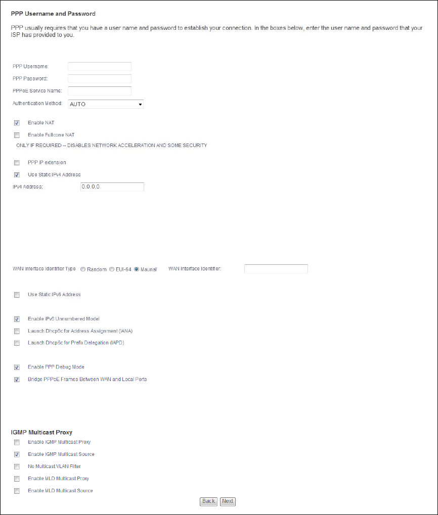
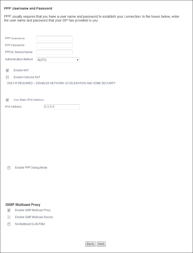
PPPoE
This screen displays when you select PPP over Ethernet (PPPoE) in the WAN Service
Configuration screen.
Figure 19 WAN Configuration: PPPoE

Chapter 3 WAN 33
Table 17 WAN Configuration: PPPoE
LABEL DESCRIPTION
PPP Username Enter the user name exactly as your ISP assigned. If assigned a name in the form
user@domain where domain identifies a service name, then enter both
components exactly as given.
PPP Password Enter the password associated with the user name above.
PPPoE Service
Name
Type the name of your PPPoE service here.
This field is not available for a PPPoA connection.
Authentication
Method
The Router supports PAP (Password Authentication Protocol) and CHAP (Challenge
Handshake Authentication Protocol). CHAP is more secure than PAP; however, PAP
is readily available on more platforms.
Use the drop-down list box to select an authentication protocol for outgoing calls.
Options are:
AUTO - Your Router accepts either CHAP or PAP when requested by this remote
node.
PAP - Your Router accepts PAP only.
CHAP - Your Router accepts CHAP only.
MSCHAP - Your Router accepts MSCHAP only. MS-CHAP is the Microsoft version of
the CHAP.
Enable NAT Select this check box to activate NAT on this connection.
Enable Fullcone
NAT
This field is available only when you select Enable NAT. Select this check box to
activate full cone NAT on this connection.
PPP IP extension Select this only if your service provider requires it. PPP IP extension extends the
service provider’s IP subnet to a single LAN computer.
• It lets only one computer on the LAN connect to the WAN.
• The public IP address from the ISP is forwarded through DHCP to the LAN
computer instead of being used on the WAN PPP interface.
• It disables NAT and the firewall.
• DHCP tells the LAN computer to use the gateway as the default gateway and
DNS server.
• The Router bridges IP packets between the WAN and LAN ports except packets
destined for the Router’s LAN IP address.
Use Static IPv4
Address
Select this option if you have a fixed IPv4 address assigned by your ISP.
IPv4 Address Enter the IPv4 address assigned by your ISP.
WAN Interface
Identifier Type
Select Random to have the Device randomly configure a WAN Identifier, which is
shown in the WAN Interface Identifier field.
Select EUI-64 to use the EUI-64 format to generate an interface ID from the MAC
address of the WAN interface.
Select Manual to manually enter a WAN Identifier as the interface ID to identify the
WAN interface. The WAN Identifier is appended to the IPv6 address prefix to create
the routable global IPv6 address.

Chapter 3 WAN 34
WAN Interface
Identifier
If you selected Random, this field is automatically configured.
If you selected Manual, enter the WAN Identifier in this field. The WAN identifier
should be unique and 64 bits in hexadecimal form. Every 16 bit block should be
separated by a colon as in XXXX:XXXX:XXXX:XXXX where X is a hexadecimal
character. Blocks of zeros can be represented with double colons as in
XXXX:XXXX::XXXX.
Use Static IPv6
Address
Select this option if you have a fixed IPv6 address assigned by your ISP.
IPv6 Address Enter the IPv6 address assigned by your ISP.
Enable IPv6
Unnumbered
Model
Select this to enable IPv6 processing on the interface without assigning an explicit
IPv6 address to the interface.
Launch Dhcp6c
for Address
Assignment
(IANA)
Select this check box to obtain an IPv6 address from a DHCPv6 server.
The IP address assigned by a DHCPv6 server has priority over the IP address
automatically generated by the Router using the IPv6 prefix from an RA.
Launch Dhcp6c
for Prefix
Delegation (IAPD)
Select this to use DHCP PD (Prefix Delegation) that enables the Device to
pass the IPv6 prefix information to its LAN hosts. The hosts can then use
the prefix to generate their IPv6 addresses.
Enable PPP Debug
Mode
Select this option to display PPP debugging messages on the console.
Bridge PPPoE
Frames Between
WAN and Local
Ports
Select this option to forward PPPoE packets from the WAN port to the LAN ports and
from the LAN ports to the WAN port.
In addition to the Router's built-in PPPoE client, you can select this to allow up to ten
hosts on the LAN to use PPPoE client software on their computers to connect to the
ISP via the Router. Each host can have a separate account and a public WAN IP
address.
This is an alternative to NAT for application where NAT is not appropriate.
Clear this if you do not need to allow hosts on the LAN to use PPPoE client software
on their computers to connect to the ISP.
Enable IGMP
Multicast Proxy
Select this check box to have the Router act as an IGMP proxy on this connection.
This allows the Router to get subscribing information and maintain a joined
member list for each multicast group. It can reduce multicast traffic significantly.
Enable IGMP
Multicast Source
Select this check box to have the Router add routing table entries based on the
IGMP traffic.
No Multicast VLAN
Filter
Select this check box to have the Router not filter multicast traffic based on its
VLAN.
Enable MLD
Multicast Proxy
Select this check box to have the Router act as an MLD proxy on this connection.
This allows the Router to get subscription information and maintain a joined
member list for each multicast group. It can reduce multicast traffic significantly.
Table 17 WAN Configuration: PPPoE (continued)
LABEL DESCRIPTION

Chapter 3 WAN 35
Enable MLD
Multicast Source
Select this check box to have the Router add routing table entries based on the MLD
traffic.
Back Click this button to return to the previous screen.
Next Click this button to continue.
Table 17 WAN Configuration: PPPoE (continued)
LABEL DESCRIPTION
Chapter 3 WAN 36
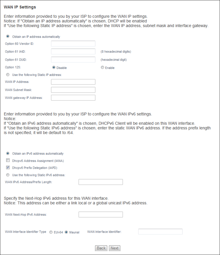
IPoE
This screen displays when you select IP over Ethernet in the WAN Service Configuration screen.
Figure 20 WAN Configuration: IPoE

Chapter 3 WAN 37
Table 18 WAN Configuration: IPoE
LABEL DESCRIPTION
Obtain an IP
address
automatically
A static IP address is a fixed IP that your ISP gives you. A dynamic IP address is not
fixed; the ISP assigns you a different one each time you connect to the Internet.
Select this if you have a dynamic IP address.
Option 60 Vendor
ID
DHCP Option 60 identifies the vendor and functionality of the Router in DHCP
requests that the Router sends to a DHCP server when getting a WAN IP address.
Enter the Vendor Class Identifier (Option 60), such as the type of the hardware or
firmware.
Option 61 IAID DHCP Option 61 identifies the Router in DHCP requests the Router sends to a DHCP
server when getting a WAN IP address. Enter the Identity Association Identifier (IAID)
of the Router. For example, the WAN connection index number.
Option 61 DUID Enter the DHCP Unique Identifier (DUID) of the Router.
Option 125 Enable this to add vendor specific information to DHCP requests that the Router
sends to a DHCP server when getting a WAN IP address.
Use the following
Static IP address
Select this if you have a static IP address.
WAN IP
Address Enter the static IP address provided by your ISP.
WAN Subnet
Mask Enter the subnet mask provided by your ISP.
WAN gateway
IP Address Enter the gateway IP address provided by your ISP.
Obtain an IPv6
address
automatically
Select this option to have the Router use the IPv6 prefix from the connected router’s
Router Advertisement (RA) to generate an IPv6 address.
Dhcpv6
Address
Assignment
Select this check box to obtain an IPv6 address from a DHCPv6 server.
The IP address assigned by a DHCPv6 server has priority over the IP address
automatically generated by the Router using the IPv6 prefix from an RA.
Dhcp6c Prefix
Delegation
(IAPD)
Select this to use DHCP PD (Prefix Delegation) that enables the Device to
pass the IPv6 prefix information to its LAN hosts. The hosts can then use
the prefix to generate their IPv6 addresses.
Use the following
Static IPv6
address
Select this option if you have a fixed IPv6 address assigned by your ISP.
WAN IPv6
Address/Prefix
Length
Enter the static IPv6 address and bit number of the IPv6 subnet mask provided by
your ISP.
WAN Next-Hop
IPv6 Address Enter the gateway IPv6 address provided by your ISP.

Chapter 3 WAN 38
WAN Interface
Identifier Type
Select Random to have the Device randomly configure a WAN Identifier, which is
shown in the WAN Interface Identifier field.
Select EUI-64 to use the EUI-64 format to generate an interface ID from the MAC
address of the WAN interface.
Select Manual to manually enter a WAN Identifier as the interface ID to identify the
WAN interface. The WAN Identifier is appended to the IPv6 address prefix to create
the routable global IPv6 address.
WAN Interface
Identifier
If you selected Random, this field is automatically configured.
If you selected Manual, enter the WAN Identifier in this field. The WAN identifier
should be unique and 64 bits in hexadecimal form. Every 16 bit block should be
separated by a colon as in XXXX:XXXX:XXXX:XXXX where X is a hexadecimal
character. Blocks of zeros can be represented with double colons as in
XXXX:XXXX::XXXX.
Back Click this button to return to the previous screen.
Next Click this button to continue.
Table 18 WAN Configuration: IPoE (continued)
LABEL DESCRIPTION

Chapter 3 WAN 39
3.3.1.4 NAT and IGMP Multicast
This screen is available only when you select IP over Ethernet in the WAN Service Configuration
screen.
Figure 21 WAN Configuration: NAT and IGMP Multicast: IPoE
Table 19 WAN Configuration: NAT and IGMP Multicast: IPoE
LABEL DESCRIPTION
Enable NAT Select this check box to activate NAT on this connection.
Enable Fullcone
NAT
Select this check box to activate full cone NAT on this connection.
This field is available only when you select Enable NAT.
Enable IGMP
Multicast Proxy
Select this check box to have the Router act as an IGMP proxy on this connection.
This allows the Router to get subscribing information and maintain a joined
member list for each multicast group. It can reduce multicast traffic significantly.
Enable IGMP
Multicast Source
Select this check box to have the Router add routing table entries based on the
IGMP traffic.

Chapter 3 WAN 40
No Multicast VLAN
Filter
Select this check box to have the Router not filter multicast traffic based on its
VLAN.
Enable MLD
Multicast Proxy
Select this check box to have the Router act as an MLD proxy on this connection.
This allows the Router to get subscription information and maintain a joined
member list for each multicast group. It can reduce multicast traffic significantly.
Enable MLD
Multicast Source
Select this check box to have the Router add routing table entries based on the MLD
traffic.
Back Click this button to return to the previous screen.
Next Click this button to continue.
Table 19 WAN Configuration: NAT and IGMP Multicast: IPoE (continued)
LABEL DESCRIPTION
Chapter 3 WAN 41
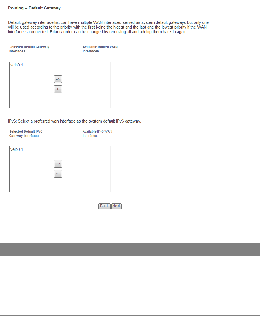
3.3.1.5 Default Gateway (PPPoE or IPoE)
The screen is not available when you select Bridging in the WAN Service Configuration screen.
Figure 22 WAN Configuration: Default Gateway
Table 20 WAN Configuration: Default Gateway
LABEL DESCRIPTION
Selected Default
Gateway
Interfaces
Select a WAN interface through which to forward the service’s traffic.
You can select multiple WAN interfaces for the device to try. The Router tries the
WAN interfaces in the order listed and uses only the default gateway of the first
WAN interface that connects; there is no backup WAN function. To change the
priority order remove them all and add them back in again.
Available Routed
WAN Interfaces
Select from these WAN interfaces.

Chapter 3 WAN 42
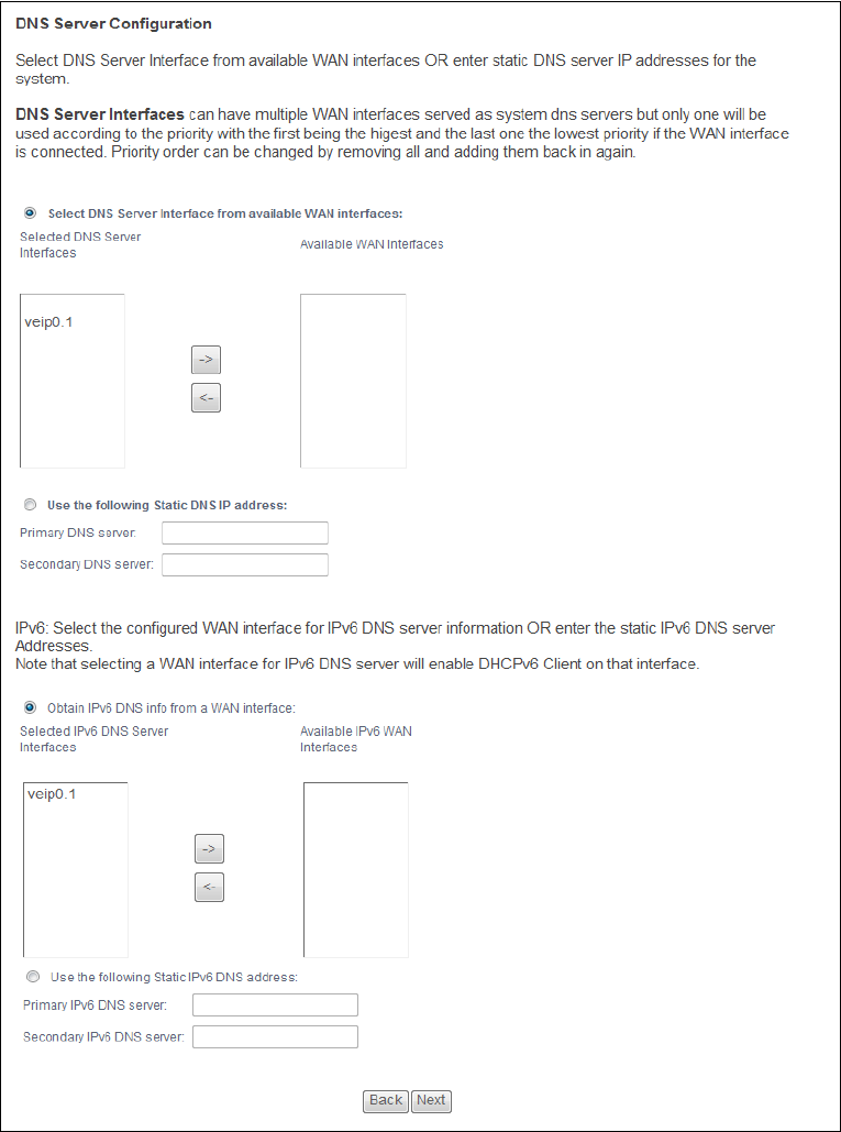
3.3.1.6 DNS Server
The screen is not available when you select Bridging in the WAN Service Configuration screen.
Selected WAN
Interface
Select a WAN interface through which to forward IPv6 traffic.
Selected Default
IPv6 Gateway
Interfaces
Select an IPv6 WAN interface through which to forward the service’s IPv6 traffic.
You can select multiple WAN interfaces for the device to try. The Router tries the
WAN interfaces in the order listed and uses only the default gateway of the first
WAN interface that connects; there is no backup WAN function. To change the
priority order remove them all and add them back in again.
Available IPv6
WAN Interfaces
Select from these IPv6 WAN interfaces.
Back Click this button to return to the previous screen.
Next Click this button to continue.
Table 20 WAN Configuration: Default Gateway (continued)
LABEL DESCRIPTION
Chapter 3 WAN 43
If you configure only one IPoE connection, you must enter the static DNS server address.
Figure 23 WAN Configuration: DNS Server: PPPoE or IPoE

Chapter 3 WAN 44
Table 21 WAN Configuration: DNS Server: PPPoE or IPoE
LABEL DESCRIPTION
Select DNS Server
Interface from
available WAN
interfaces
Select this to have the Router get the DNS server addresses from one of the
Router’s WAN interfaces.
Selected DNS
Server
Interfaces
Select a WAN interface through which to get DNS server addresses.
You can select multiple WAN interfaces for the device to try. The Router tries the
WAN interfaces in the order listed and uses only the DNS server information of the
first WAN interface that connects; there is no backup WAN function. To change the
priority order remove them all and add them back in again.
Available WAN
Interfaces These are the WAN interfaces you can select from.
Use the following
Static DNS IP
address
Select this to have the Router use the DNS server addresses you configure
manually.
Primary DNS
server Enter the first DNS server address assigned by the ISP.
Secondary
DNS server Enter the second DNS server address assigned by the ISP.
Obtain IPv6 DNS
info from a WAN
interface
Select this to have the Router get the IPv6 DNS server addresses from the ISP
automatically.
WAN Interface
selected Select a WAN interface through which you want to obtain the IPv6 DNS related
information.
Use the following
Static IPv6 DNS
address
Select this to have the Router use the IPv6 DNS server addresses you configure
manually.
Primary IPv6
DNS server Enter the first IPv6 DNS server address assigned by the ISP.
Secondary
IPv6 DNS
server
Enter the second IPv6 DNS server address assigned by the ISP.
Back Click this button to return to the previous screen.
Next Click this button to continue.
Chapter 3 WAN 45
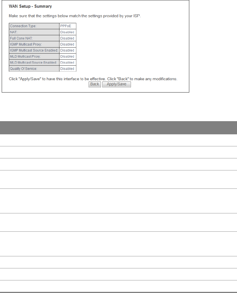
3.3.1.7 Configuration Summary
This read-only screen shows the current WAN connection settings.
Figure 24 WAN Configuration: Configuration Summary
Table 22 WAN Configuration: Configuration Summary
LABEL DESCRIPTION
Connection Type This is the encapsulation method used by this connection.
NAT This shows whether NAT is active or not for this connection.
Full Cone NAT This shows whether full cone NAT is active or not for this connection.
IGMP Multicast
Proxy
This shows whether IGMP proxy is activated or not for this connection.
IGMP is not available when the connection uses the bridging service.
IGMP Multicast
Source Enabled
This shows whether IGMP source enable is activated or not for this
connection. IGMP source enable has the Router add routing table entries
based on the IGMP traffic.
MLD Multicast
Proxy
This shows whether MLD proxy is activated or not for this connection. MLD
is not available when the connection uses the bridging service.
MLD Multicast
Source Enabled
This shows whether MLD source enable is activated or not for this
connection. MLD source enable has the Router add routing table entries
based on the MLD traffic.
Quality Of Service This shows whether QoS is active or not for this connection.
Back Click this button to return to the previous screen.
Apply/Save Click this button to save your changes.
4
Chapter
Chapter 4 LAN 46
CHAPTER 4
Chapter 4 LAN
4.1 LAN Setup
Click Advanced Setup > LAN to open the LAN Setup screen. Use this screen to set the Local Area
Network IP address and subnet mask of your Router and configure the DNS server information that
the Router sends to the DHCP client devices on the LAN.

Chapter 4 LAN 47
Figure 25 LAN Setup

Chapter 4 LAN 48
Table 23 LAN Setup
LABEL DESCRIPTION
Group Name Select the LAN interface for which to configure the IP address and subnet mask.
IP Address Enter the LAN IP address you want to assign to your Router. The factory default is
192.168.1.1.
Subnet Mask Type the subnet mask of your network. The factory default is 255.255.255.0. Your
Router automatically computes the subnet mask based on the IP address you enter,
so do not change this field unless you are instructed to do so.
Enable IGMP
Snooping
IGMP (Internet Group Multicast Protocol) is a network-layer protocol used to
establish membership in a multicast group.
Select this to activate IGMP Snooping. This allows the Router to passively learn
memberships in multicast groups. Otherwise, clear the option to deactivate it.
Select Standard Mode to have the Router forward multicast packets to a port that
joins the multicast group and broadcast unknown multicast packets from the WAN
to all LAN ports.
Select Blocking Mode to have the Router block all unknown multicast packets from
the WAN.
Enable IGMP LAN to
LAN Multicast
Select this to allow IGMP multicast traffic to travel between the LAN ports.
Disable DHCP
Server
Select this to have the Router not provide DHCP services. Users must configure LAN
devices with manual network settings if you do not have another DHCP server on
the network.
Enable DHCP Server Select this to have the Router serve as the DHCP server for the network to assign IP
addresses and provide subnet mask, gateway, and DNS server information to LAN
devices.
Start IP Address This field specifies the first of the contiguous addresses in the IP address pool.
End IP Address This field specifies the last of the contiguous addresses in the IP address pool.
Leased Time
(hour) Specify for how many hours to assign an IP address to a LAN device before making it
available for reassignment to other systems.
Static IP Lease
List Use this table to assign IP addresses on the LAN to specific computers based on
their MAC Addresses.
MAC Address The MAC (Media Access Control) of a LAN device to which the entry’s IP address is
assigned.
IP Address This field displays the IP address reserved for the LAN device with the entry’s MAC.
Remove Select entries and click the Remove Entries button to delete them.
Add Entries Click this button to create a new static IP lease entry.
Enable DHCP
Conditional Serving
Pool
Select this to enable the DHCP conditional serving pool for IPTV set-top boxes. DHCP
server will offer IP address from the conditional pool if the DHCP request sent from a
set-top box contains the specific Vendor ID.

Chapter 4 LAN 49
4.1.1 Add DHCP Static IP Lease
Click Add Entries in the LAN Setup screen to display the following screen.
Figure 26 Add DHCP Static IP Lease
Gateway Enter the IPTV server’s IP address.
Subnet Mask Enter the IPTV server’s subnet mask.
Pool Start/End Specify the first and last of the contiguous addresses in the IPTV server’s IP address
pool.
DNS Server 1/2 Enter the IPTV server’s first/second DNS server IP address.
VendorID Specify the IPTV’s vendor ID.
VendorID Mode Specify the IPTV’s vendor ID mode type.
VendorID Exclude Specify if you want to enable vendor ID exclude.
Option240 State Select Enabled to have the Router assign DHCP option 240 to the LAN set top box.
Option240 Value Enter the option 240 value.
Configure the
second IP Address
and Subnet Mask
for LAN interface
Select the check box to use IP alias to configure another LAN network for the Router.
IP alias partitions a physical network into different logical networks over the same
Ethernet interface. The Router supports multiple logical LAN interfaces via its
physical Ethernet interface with the Router itself as the gateway for the LAN
network. You can also configure firewall rules to control access to the LAN's logical
network (subnet).
IP Address Enter the second LAN IP address of your Router in dotted decimal notation.
Subnet Mask Type the subnet mask of your network in dotted decimal notation, for example
255.255.255.0 (factory default).
Table 23 LAN Setup (continued)
LABEL DESCRIPTION
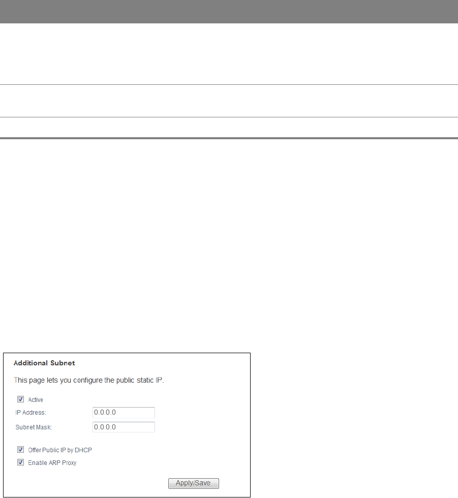
Table 24 Add DHCP Static IP Lease
LABEL DESCRIPTION
MAC Address Enter the MAC address of a computer on your LAN.
Every Ethernet device has a unique MAC (Media Access Control) address. The MAC
address is assigned at the factory and consists of six pairs of hexadecimal characters,
for example, 00:A0:C5:00:00:02.
IP Address Enter the IP address that you want to assign to the computer on your LAN with the
MAC address that you will also specify.
Apply/Save Click this button to save your changes and go back to the previous screen.
Chapter 4 LAN 50
4.2 LAN Additional Subnet
Click Advanced Setup > LAN > Additional Subnet to open the Additional Subnet screen. Use this
screen to configure IP alias and public static IP.
IP alias allows you to partition a physical network into different logical networks over the same
Ethernet interface. The Router supports multiple logical LAN interfaces via its physical Ethernet
interface with the Router itself as the gateway for the LAN network. When you use IP alias, you can
also configure firewall rules to control access to the LAN's logical network (subnet).
If your ISP provides the Public LAN service, the Router may use an LAN IP address that can be
accessed from the WAN.
Figure 27 LAN Additional Subnet
Chapter 4 LAN 51
Table 25 LAN Additional Subnet
LABEL DESCRIPTION
Active Select the check box to configure a LAN network for the Router.
IP Address Enter the IP address of your Router in dotted decimal notation.
IP Subnet Mask Your Router will automatically calculate the subnet mask based on the IP address
that you assign. Unless you are implementing subnetting, use the subnet mask
computed by the Router.
Offer Public IP by
DHCP
Select the check box to enable the Router to provide public IP addresses by DHCP
server.
Enable ARP Proxy Select the check box to enable the ARP (Address Resolution Protocol) proxy.
Apply/Save Click this button to save your changes and go back to the previous screen.
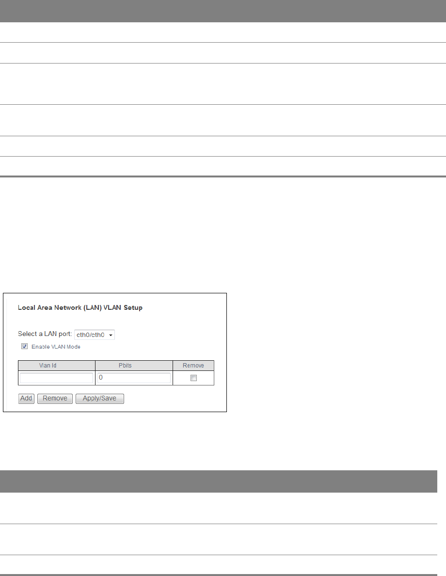
4.3 LAN VLAN
Click Advanced Setup > LAN > LAN VLAN to open this screen. Use this screen to control the VLAN
ID and IEEE 802.1p priority tags of traffic sent out through individual LAN ports.
Figure 28 LAN VLAN
Table 26 LAN VLAN
LABEL DESCRIPTION
Select a LAN
port
eth0 ~ eth3 represent the Ethernet LAN ports 1 ~ 4. Select a port.
Enable VLAN
Mode
Select this to use VLAN on the LAN port you selected.
VLAN ID Specify the VLAN ID (from 0 to 4094) to use for this LAN port’s downstream traffic.

Chapter 4 LAN 52
Pbits Set the IEEE 802.1p priority tag value (o to 7) to use for the LAN port’s downstream
traffic. The larger the number, the higher the priority.
Remove Select an entry and click the Remove button to delete it.
Add Click this button to create a new LAN VLAN setting entry.
Apply/Save Click this button to save your changes and go back to the previous screen.
Table 26 LAN VLAN (continued)
LABEL DESCRIPTION
Chapter 4 LAN 53
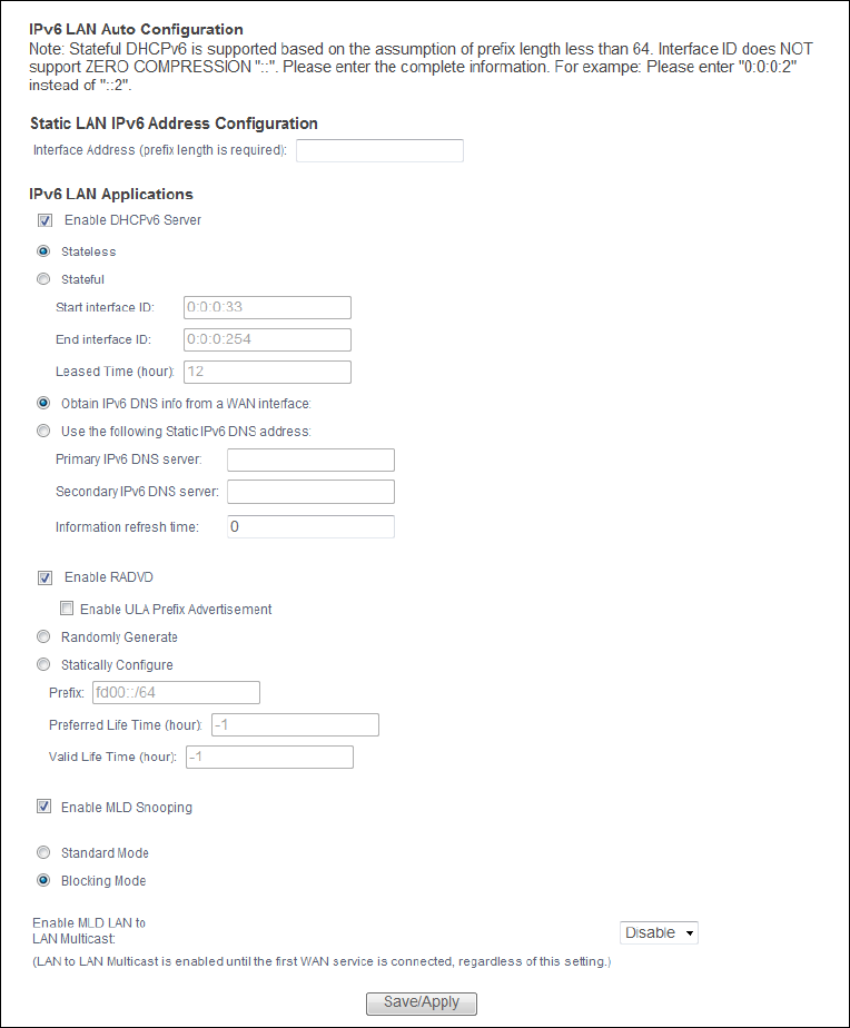
4.4 IPv6 LAN Auto Configuration
Click Advanced Setup > LAN > IPv6 Autoconfig to open the IPv6 LAN Auto Configuration screen.
Use this screen to set the Local Area Network interface IPv6 settings.
Figure 29 IPv6 LAN Auto Configuration

Chapter 4 LAN 54
The following table describes the fields in this screen.
Table 27 IPv6 LAN Auto Configuration
LABEL DESCRIPTION
Interface Address To use a static IPv6 address, enter the IPv6 address prefix and prefix length that
the Router uses for the LAN IPv6 address.
The IPv6 prefix length specifies how many most significant bits (starting from
the left) in the address compose the network address. This field displays the bit
number of the IPv6 subnet mask.
Enable DHCPv6
Server
Select this to have the Router act as a DHCPv6 server and pass IPv6 addresses,
DNS server and domain name information to DHCPv6 clients.
Stateless Select this to have the Router use IPv6 stateless autoconfiguration.
Stateful Select this to have the Router use IPv6 stateful autoconfiguration.
Start interface ID: specify the first IPv6 address in the pool of addresses that
can be assigned to DHCPv6 clients.
End interface ID: specify the last IPv6 address in the pool of addresses that can
be assigned to DHCPv6 clients.
Leased Time (hour): Specify for how many hours to assign an IPv6 address to a
DHCPv6 client before making it available for reassignment to other systems.
Obtain IPv6 DNS info
from a WAN interface
Select this to have the Router get the IPv6 DNS server addresses from the ISP
automatically.
Use the following
Static IPv6 DNS
address
Select this to have the Router use the IPv6 DNS server addresses you configure
manually.
Primary IPv6 DNS
server Enter the first IPv6 DNS server address assigned by the ISP.
Secondary IPv6
DNS server Enter the second IPv6 DNS server address assigned by the ISP.
Enable RADVD Select this to have the Router send router advertisement messages to the LAN
hosts.
Router advertisement is a response to a router solicitation or a periodical
multicast advertisement from a router to advertise its presence and other
parameters, such as IPv6 prefix and DNS information. Router solicitation is a
request from a host to locate a router that can act as the default router and
forward packets.
Note: The LAN hosts neither generate global IPv6 addresses nor communicate
with other networks if you disable this feature.
Enable ULA Prefix
Advertisement Select this to send Unique Local IPv6 Unicast Addresses (ULA) advertisement
messages to the LAN hosts.
Randomly
Generate Select this to automatically create a LAN IPv6 address prefix.

Chapter 4 LAN 55
Network Connections: My Network Places: Properties: Example
Statically
Configure Select this to send a fixed LAN IPv6 address prefix.
Prefix: enter the IPv6 prefix and length the Router uses to generate the LAN
IPv6 address. The prefix length specifies how many most significant bits (starting
from the left) in the address compose the network address. This field displays
the bit number of the IPv6 subnet mask.
Preferred Life Time (hour): enter the preferred lifetime for the prefix. -1 means
no time limit.
Valid Life Time (hour): enter the valid lifetime for the prefix. Set this greater
than or equal to the preferred life time. -1 means no time limit.
Enable MLD Snooping Select this to have the Router check Multicast Listener Discovery (MLD) packets
to learn the multicast group membership. This helps reduce multicast traffic.
Standard Mode Select this to have the Router forward multicast packets to a port that joins the
multicast group and broadcast unknown multicast packets from the WAN to all
LAN ports.
Blocking Mode Select this to have the Router block all unknown multicast packets from the
WAN.
Enable MLD LAN to
LAN Multicast
Select this to allow MLD multicast traffic to travel between the LAN ports.
Save/Apply Click this button to save your changes.
Table 27 IPv6 LAN Auto Configuration (continued)
LABEL DESCRIPTION

5
Chapter
Chapter 5 VPN 56
CHAPTER 5
Chapter 5 VPN
5.1 L2TP VPN Client
Use this screen to manage WAN service Layer 2 Tunneling Protocol (L2TP) client settings for
connecting to L2TP servers.
Click Advanced Setup > VPN > L2TP Client to open this screen as shown next.
Figure 30 L2TP Client
This screen contains the following fields:
Table 28 L2TP Client
LABEL DESCRIPTION
Tunnel Name This is the name of this client connection.
LNS Ip Address This is the IP address of the L2TP VPN server.
Remove Select entries and click the Remove button to delete them.
Status This is the connection status.
Add Click this to add a VPN client profile.
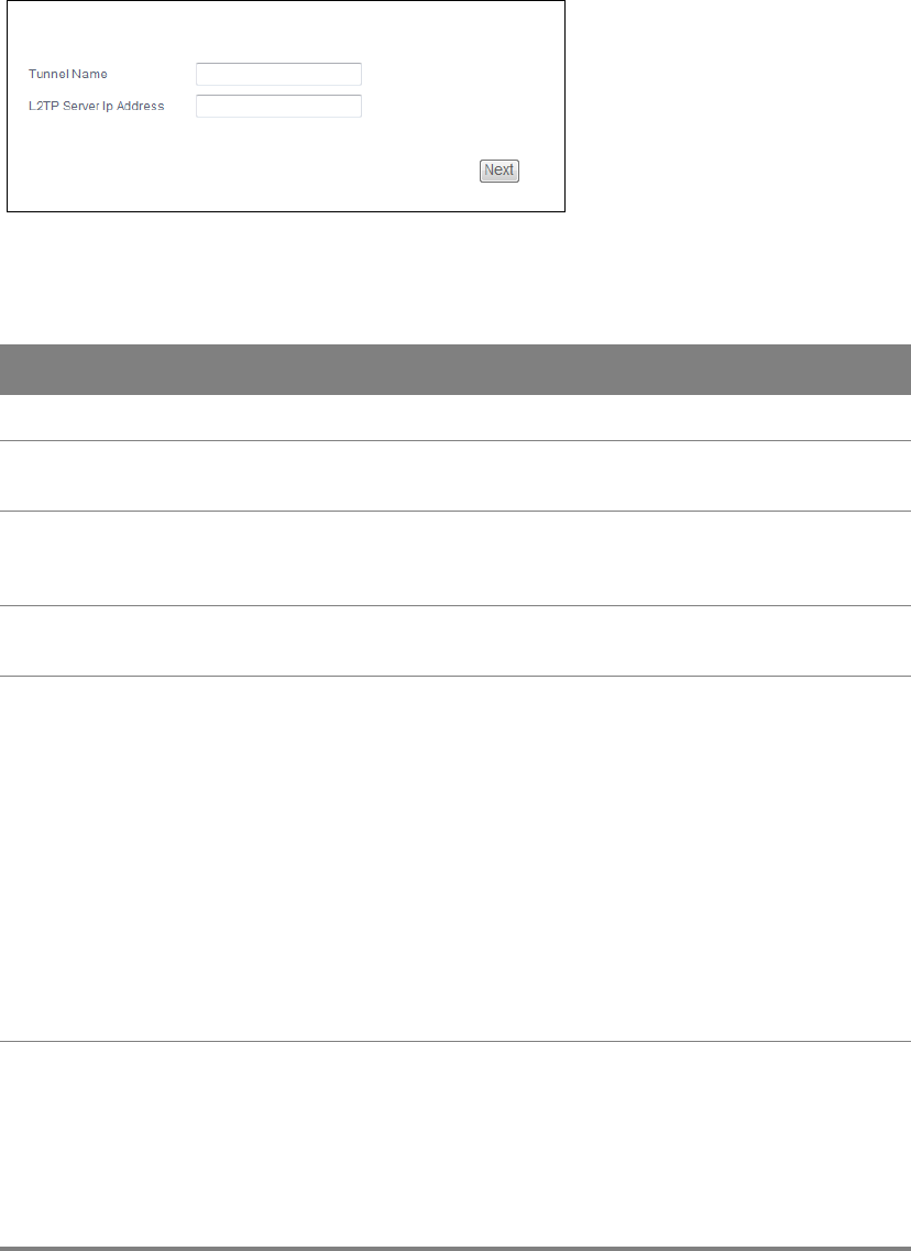
5.1.1 L2TP VPN Client: Add
Click Advanced Setup > VPN > L2TP Client > Add to configure L2TP WAN service settings for
connecting to L2TP servers.
Chapter 5 VPN 57
5.1.1.1 Name and Server IP Address
This screen displays when you add a new L2TP client WAN service.
Figure 31 L2TP Client: Add
This screen contains the following fields:
Table 29 L2TP Client: Add
LABEL DESCRIPTION
Tunnel Name Enter the name for this client connection.
L2TP Server Ip
Address
Enter the IP address of the L2TP server.
L2TP Protocol
Version
Select the L2TP Protocol Version 2 or 3. L2TPv2 is a standard method for
tunneling Point-to-Point Protocol (PPP) while L2TPv3 provides improved
support for other types of networks including frame relay and ATM.
NAT Mode? Select Yes if the client will be located behind a NAT enabled router. This will
allow multiple clients using NAT to connect with L2TP at the same time.
Auth Protocol Select the Authentication Protocol allowed for the connection. Options are:
PAP - Password Authentication Protocol (PAP) authentication occurs in clear
text and does not use encryption. It’s probably not a good idea to rely on this
for security.
CHAP - Challenge Handshake Authentication Protocol (CHAP) provides
authentication through a shared secret key and uses a three way handshake.
MSCHAPv1 - Microsoft CHAP v1 (MSCHAPv1) provides authentication
through a shared secret key and uses a three way handshake. It provides
improved usability with Microsoft products.
MSCHAPv2 - Microsoft CHAP v2 (MSCHAPv2) provides encryption through a
shared secret key and uses a three way handshake. It provides additional
security over MSCHAPv1, including two-way authentication.
MPPE
Encryption
If MSCHAPv1 or MSCHAPv2 is selected as an Auth Protocol, use the drop-
down list box to select the type of Microsoft Point-to-Point Encryption
(MPPE). Options are:
MPPE 40 - MPPE with 40 bit session key length
MPPE 128 - MPPE with 128 bit session key length
Auto - Automatically select either MPPE 40 or MPPE 128

Chapter 5 VPN 58
MPPE Stateful? Select Yes to enable stateful MPPE encryption. This can increase
performance over stateless MPPE, but should not be used in lossy network
environments like layer two tunnels over the Internet.
User Name Enter the user name for connecting to the L2TP server.
Password Enter the password for connecting to the L2TP server.
Retype Retype the password for connecting to the L2TP server.
Get IP
automatically
Select Yes to have the L2TP server assign a local IP address to the client.
Assign IP
Address
Enter the IP address for the client. Ensure that the IP address is configured to
be allowed on the L2TP server.
Idle Timeout Enter the time in minutes to timeout L2TP connections.
Table 29 L2TP Client: Add (continued)
LABEL DESCRIPTION
Chapter 5 VPN 59
5.1.1.2 PPP
This screen displays second when you add a new L2TP client WAN service.
Figure 32 L2TP Client Add: PPP

Chapter 5 VPN 60
This screen contains the following fields:
Table 30 L2TP Client Add: PPP
LABEL DESCRIPTION
PPP Username Enter the user name exactly as your ISP assigned. If assigned a name in the
form user@domain where domain identifies a service name, then enter both
components exactly as given.
PPP Password Enter the password associated with the user name above.
PPPoE Service
Name
Type the name of your PPPoE service here.
This field is not available for a PPPoA connection.
Authentication
Method
The Router supports PAP (Password Authentication Protocol) and CHAP
(Challenge Handshake Authentication Protocol). CHAP is more secure than
PAP; however, PAP is readily available on more platforms.
Use the drop-down list box to select an authentication protocol for outgoing
calls. Options are:
AUTO - Your Router accepts either CHAP or PAP when requested by this
remote node.
PAP - Your Router accepts PAP only.
CHAP - Your Router accepts CHAP only.
MSCHAP - Your Router accepts MSCHAP only. MS-CHAP is the Microsoft
version of the CHAP.
Enable NAT Select this check box to activate NAT on this connection.
Enable Fullcone
NAT
This field is available only when you select Enable NAT. Select this check box
to activate full cone NAT on this connection.
Tunnel Name Enter the name for this client connection.
Use Static IPv4
Address
Select this option if you have a fixed IPv4 address assigned by your ISP.
IPv4 Address Enter the IPv4 address assigned by your ISP.
Enable PPP
Debug Mode
Select this option to display PPP debugging messages on the console.
Enable IGMP
Multicast Proxy
Select this check box to have the Router act as an IGMP proxy on this
connection. This allows the Router to get subscribing information and
maintain a joined member list for each multicast group. It can reduce
multicast traffic significantly.
Enable IGMP
Multicast Source
Select this check box to have the Router add routing table entries based on
the IGMP traffic.
No Multicast
VLAN Filter
Select this check box to have the Router not filter multicast traffic based on
its VLAN.
Back Click this button to return to the previous screen.
Next Click this button to continue.

Chapter 5 VPN 61
5.1.1.3 L2TP Client Add: Configuration Summary
This read-only screen shows the current L2TP WAN connection settings.
Figure 33 L2TP Client Add: Configuration Summary
Table 31 L2TP Client Add: Configuration Summary
LABEL DESCRIPTION
Connection Type This is the encapsulation method used by this connection.
NAT This shows whether NAT is active or not for this connection.
Full Cone NAT This shows whether full cone NAT is active or not for this connection.
IGMP Multicast
Proxy
This shows whether IGMP proxy is activated or not for this connection.
IGMP is not available when the connection uses the bridging service.
IGMP Multicast
Source Enabled
This shows whether IGMP source enable is activated or not for this
connection. IGMP source enable has the Router add routing table entries
based on the IGMP traffic.
MLD Multicast
Proxy
This shows whether MLD proxy is activated or not for this connection.
MLD Multicast
Source Enabled
This shows whether MLD source enable is activated or not for this
connection. MLD source enable has the Router add routing table entries
based on the MLD traffic.
Quality Of Service This shows whether QoS is active or not for this connection.
Back Click this button to return to the previous screen.
Apply/Save Click this button to save your changes.

6
Chapter
Chapter 6 Network Address Translation (NAT) 62
CHAPTER 6
Chapter 6 Network Address Translation
(NAT)
6.1 Virtual Servers
Click Advanced Setup > NAT > Virtual Servers to open the screen where you manage the list of
virtual server rules.
A virtual server set is a list of inside (behind NAT on the LAN) servers, for example, web or FTP, that
you can make visible to the outside world even though NAT makes your whole inside network
appear as a single computer to the outside world.
Many residential broadband ISP accounts do not allow you to run any server processes
(such as a Web or FTP server) from your location. Your ISP may periodically check for
servers and may suspend your account if it discovers any active services at your location. If
you are unsure, refer to your ISP.
Figure 34 Virtual Servers
Table 32 Virtual Servers
LABEL DESCRIPTION
Add Click this button to create a new entry.
Remove Select entries and click the Remove button to delete them.

Chapter 6 Network Address Translation (NAT) 63
6.1.1 Virtual Servers Add
This screen lets you create or edit a virtual server rule. Click Add in the Virtual Servers screen to
open the following screen.
Server Name This field displays the name of the service used by the packets for this virtual server.
External Port
Start
This is the first external port number that identifies a service.
External Port
End
This is the last external port number that identifies a service.
Protocol This show whether the virtual server applies to TCP traffic, UDP traffic, or both.
Internal Port
Start
This is the first internal port number that identifies a service.
Internal Port
End
This is the last internal port number that identifies a service.
Server IP
Address
This field displays the inside IP address of the server.
WAN Interface This field displays the WAN interface through which the service is forwarded.
Current UPNP
Rule Listing
Universal Plug and Play (UPnP) is a distributed, open networking standard that uses
TCP/IP for simple peer-to-peer network connectivity between devices. A UPnP device
can dynamically join a network, obtain an IP address, convey its capabilities and learn
about other devices on the network. In turn, a device can leave a network smoothly
and automatically when it is no longer in use.
These are the rules the Router has created using UPnP.
External Port This is the external port number that identifies a service.
Internal This is the internal port number that identifies a service.
Client IP This is the IP address of the device for which the Router created the UPnP rule.
Protocol This is the protocol of the traffic for which the Router created the UPnP rule.
Table 32 Virtual Servers (continued)
LABEL DESCRIPTION
Chapter 6 Network Address Translation (NAT) 64
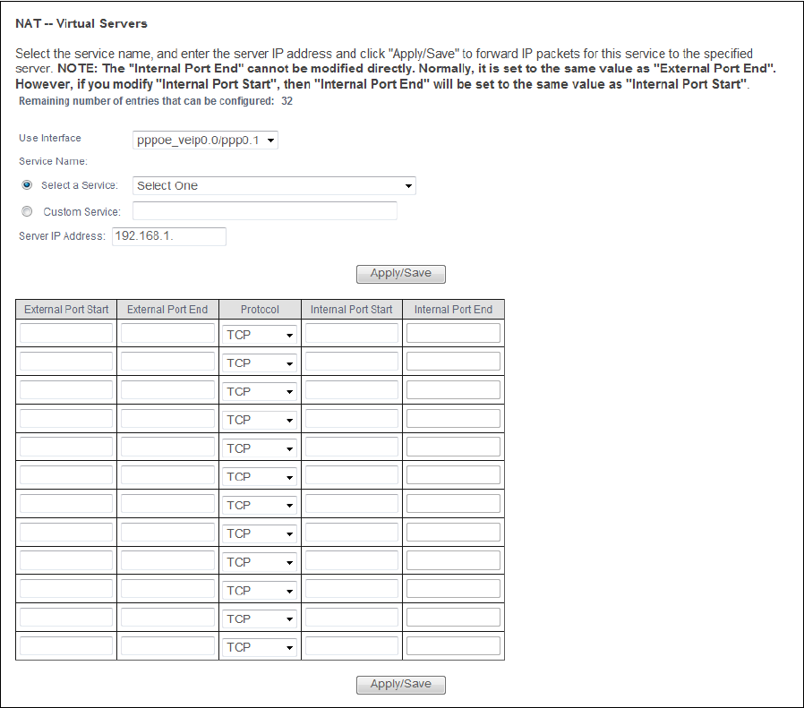
You may enter a single port number or a range of port numbers to be forwarded, and the local IP
address of the desired server. The port number identifies a service; for example, web service is on
port 80 and FTP on port 21. In some cases, such as for unknown services or where one server can
support more than one service (for example both FTP and web service), it might be better to specify
a range of port numbers. You can allocate a server IP address that corresponds to a port or a range
of ports.
Figure 35 Virtual Servers Add

Table 33 Virtual Servers Add
LABEL DESCRIPTION
Use Interface Select a WAN interface for which you want to configure a virtual server rules.
Service Name Select a Service: use the drop-down list to select a service.
Custom Service: type a name to specify a different service.
Server IP
Address
Enter the inside IP address of the LAN device to which the virtual server forwards
traffic.
Apply/Save Click this button to save your changes.
External Port
Start
Enter the original destination port for the packets.
To forward only one port, enter the port number again in the External End Port field.
To forward a series of ports, enter the start port number here and the end port
number in the External End Port field.
External Port
End
Enter the last port of the original destination port range.
To forward only one port, enter the port number in the External Start Port field above
and then enter it again in this field.
To forward a series of ports, enter the last port number in a series that begins with the
port number in the External Start Port field above.
Protocol Select the protocol supported by this virtual server. Choices are TCP, UDP, or TCP/UDP.
Internal Port
Start
Enter the port number here to which you want the Router to translate the incoming
port. For a range of ports, enter the first number of the range to which you want the
incoming ports translated.
Internal Port
End
Enter the last port of the translated port range.
Apply/Save Click this button to save your changes.
Chapter 6 Network Address Translation (NAT) 65
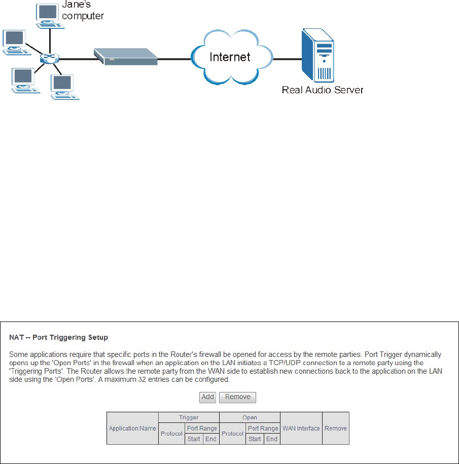
6.2 Port Triggering
Some services use a dedicated range of ports on the client side and a dedicated range of ports on
the server side. With regular port forwarding you set a forwarding port in NAT to forward a service
(coming in from the server on the WAN) to the IP address of a computer on the client side (LAN). The
problem is that port forwarding only forwards a service to a single LAN IP address. In order to use
the same service on a different LAN computer, you have to manually replace the LAN computer's IP
address in the forwarding port with another LAN computer's IP address.
Chapter 6 Network Address Translation (NAT) 66
Trigger port forwarding solves this problem by allowing computers on the LAN to dynamically take
turns using the service. The Router records the IP address of a LAN computer that sends traffic to
the WAN to request a service with a specific port number and protocol (a "trigger" port). When the
Router's WAN port receives a response with a specific port number and protocol ("open" port), the
Router forwards the traffic to the LAN IP address of the computer that sent the request. After that
computer’s connection for that service closes, another computer on the LAN can use the service in
the same manner. This way you do not need to configure a new IP address each time you want a
different LAN computer to use the application.
For example:
Figure 36 Trigger Port Forwarding Process: Example
1Jane requests a file from the Real Audio server (port 7070).
2Port 7070 is a “trigger” port and causes the Router to record Jane’s computer IP address. The Router
associates Jane's computer IP address with the "open" port range of 6970-7170.
3The Real Audio server responds using a port number ranging between 6970-7170.
4The Router forwards the traffic to Jane’s computer IP address.
5Only Jane can connect to the Real Audio server until the connection is closed or times out. The
Router times out in three minutes with UDP (User Datagram Protocol) or two hours with TCP/IP
(Transfer Control Protocol/Internet Protocol).
Click Advanced Setup > NAT > Port Triggering to manage your Router’s trigger port settings.
Figure 37 Port Triggering

Table 34 Port Triggering
LABEL DESCRIPTION
Add Click this to create a new rule.
Remove Select entries and click the Remove button to delete them.
#This is the index number of the entry.
Status This field displays whether the port triggering rule is active or not. A yellow bulb
signifies that this rule is active. A gray bulb signifies that this rule is not active.
Application
Name
This field displays the name of the service used by this rule.
Trigger
Protocol
This is the trigger transport layer protocol.
Trigger Port
Range Start
The trigger port is a port (or a range of ports) that causes (or triggers) the Router to
record the IP address of the LAN computer that sent the traffic to a server on the WAN.
This is the first port number that identifies a service.
Trigger Port
Range End
This is the last port number that identifies a service.
Open
Protocol
This is the open transport layer protocol.
Open Port
Range Start
The open port is a port (or a range of ports) that a server on the WAN uses when it sends
out a particular service. The Router forwards the traffic with this port (or range of ports)
to the client computer on the LAN that requested the service.
This is the first port number that identifies a service.
Open Port
Range End
This is the last port number that identifies a service.
WAN Interface This field shows the WAN interface through which the service is forwarded.
Chapter 6 Network Address Translation (NAT) 67
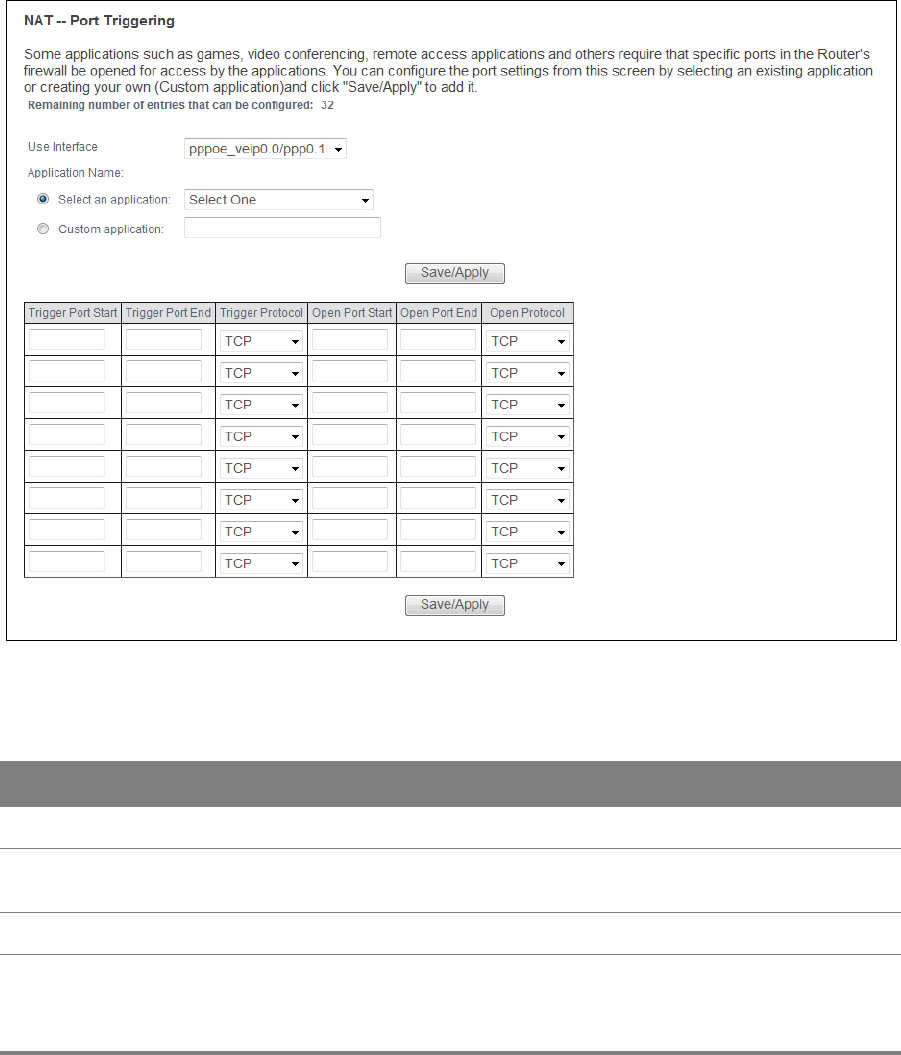
Chapter 6 Network Address Translation (NAT) 68
6.2.1 Add Port Triggering Rule
This screen lets you create new port triggering rules. Click Add in the Port Triggering screen to
open the following screen.
Figure 38 Port Triggering: Add
Table 35 Port Triggering: Add
LABEL DESCRIPTION
User Interface Select a WAN interface for which you want to configure port triggering rules.
Application
Name
Choose an application from the drop-down list or select Custom application and enter
a name to identify this rule using keyboard characters (A-Z, a-z, 1-2 and so on).
Save/Apply Click this button to save your changes.
Trigger Port
Start
The trigger port is a port (or a range of ports) that causes (or triggers) the Router to
record the IP address of the LAN computer that sent the traffic to a server on the WAN.
Type a port number or the starting port number in a range of port numbers.

Chapter 6 Network Address Translation (NAT) 69
Trigger Port
End
Type a port number or the ending port number in a range of port numbers.
Trigger
Protocol
Select the transport layer protocol from TCP, UDP, or TCP/UDP.
Open Port
Start
The open port is a port (or a range of ports) that a server on the WAN uses when it sends
out a particular service. The Router forwards the traffic with this port (or range of ports)
to the client computer on the LAN that requested the service.
Type a port number or the starting port number in a range of port numbers.
Open Port
End
Type a port number or the ending port number in a range of port numbers.
Open
Protocol
Select the transport layer protocol from TCP, UDP, or TCP/UDP.
Save/Apply Click this button to save your changes.
Table 35 Port Triggering: Add (continued)
LABEL DESCRIPTION
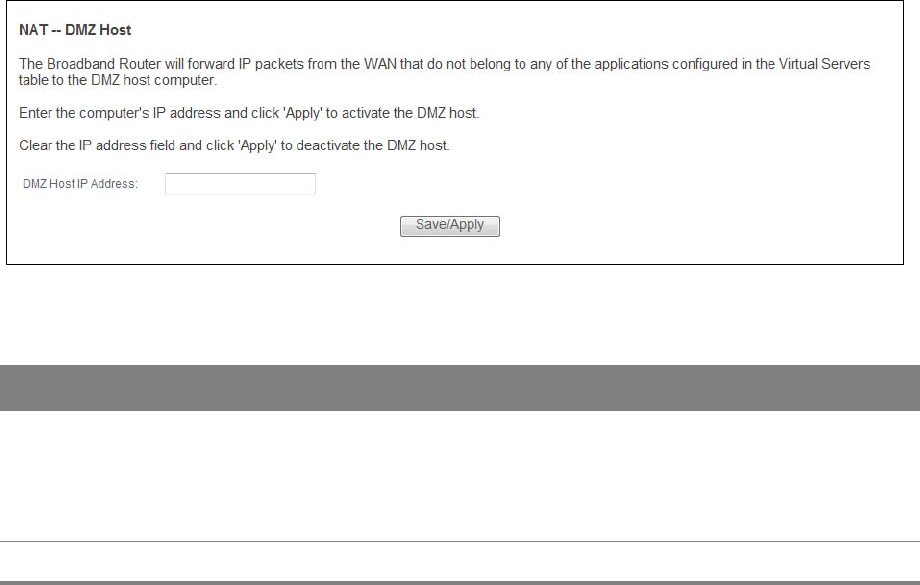
Chapter 6 Network Address Translation (NAT) 70
6.3 DMZ Host
Click Advanced Setup > NAT > DMZ Host to specify the IP address of a default server to receive
packets from ports not specified in the Port Forwarding screen.
Figure 39 DMZ Host
Table 36 DMZ Host
LABEL DESCRIPTION
DMZ Host IP
Address
Enter the IP address which receives packets from ports that are not specified in the Port
Forwarding screen.
Note: If you do not assign a default server, the Router discards all packets received for
ports not specified in the virtual server configuration.
Save/Apply Click this button to save your changes.
6.4 SIP ALG
Click Advanced Setup > NAT > SIP ALG to enable and disable the NAT Application Layer Gateway (ALG)
in the Router.
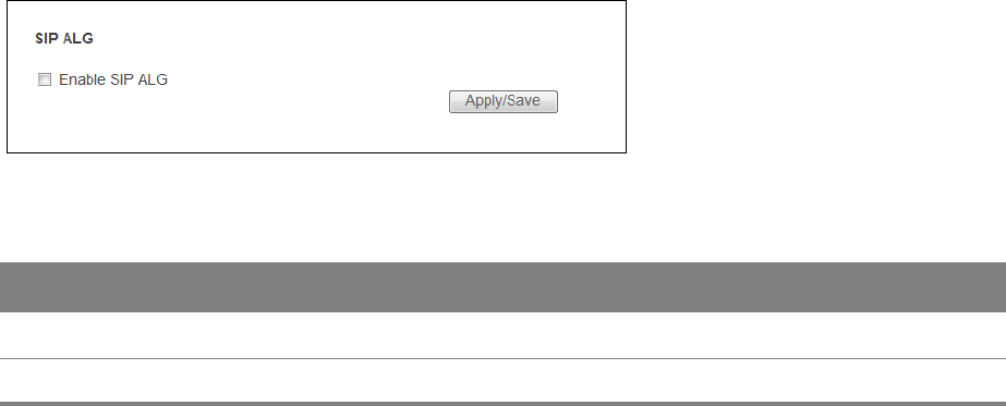
Chapter 6 Network Address Translation (NAT) 71
The SIP ALG allows SIP calls to pass through NAT by examining and translating IP addresses
embedded in the data stream. When the Router registers with the SIP register server, the SIP ALG
translates the Router’s private IP address inside the SIP data stream to a public IP address. You do
not need to use STUN or an outbound proxy if you enable the SIP ALG.
Figure 40 SIP ALG
Table 37 SIP ALG
LABEL DESCRIPTION
Enable SIP ALG Enable this to make sure SIP (VoIP) works correctly with port-forwarding.
Apply/Save Click this button to save your changes.
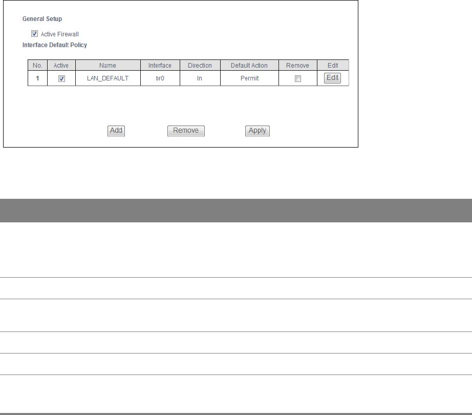
7
Chapter
Chapter 7 Firewall 72
CHAPTER 7
Chapter 7 Firewall
7.1 Firewall General
Use this screen to enable or disable the firewall and manage the default policies (filters). Click
Advanced Setup > Firewall to open the General screen.
Figure 41 Firewall General
Table 38 Firewall General
LABEL DESCRIPTION
Active
Firewall
Select this check box to activate the firewall. The Router performs access control and
protects against Denial of Service (DoS) attacks when the firewall is activated. By default the
firewall allows traffic from all interfaces to go to all interfaces. Configure firewall interface
default policies to block specific traffic directions or firewall rules to block specific traffic.
No. This displays the index number of the default firewall policy.
Active This field displays whether a policy is turned on or not. Select the check box to enable the
policy. Clear the check box to disable the policy.
Name This displays the name of the policy.
Interface This displays the LAN or WAN interface(s) to which this policy is applied.
Direction This displays the direction of travel of packets (In and Out).
Firewall rules are grouped based on the direction of travel of packets to which they apply.
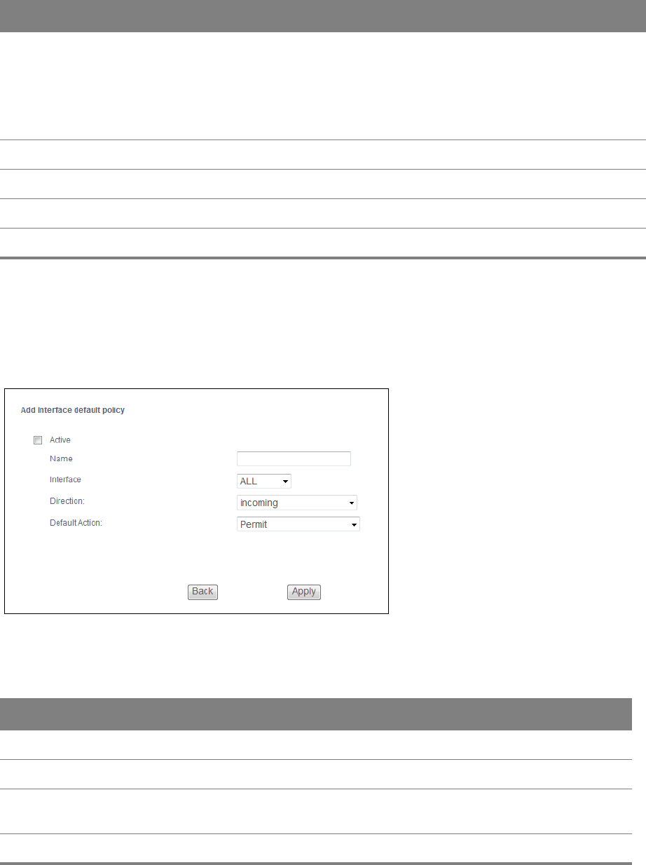
Chapter 7 Firewall 73
7.1.1 Default Policy Configuration
In the Firewall General screen, click Add or click an entry’s Edit icon to configure a firewall policy.
Figure 42 Default Policy
Default
Action
This displays the default action that the firewall is to take on packets that are traveling in the
selected direction and do not match any of the firewall rules.
Drop: the Router silently discards the packets without sending a TCP reset packet or an ICMP
destination-unreachable message to the sender.
Permit: the Router allows the passage of the packets.
Remove Select entries and click the Remove button to delete them.
Edit Click the Edit button to go to the screen where you can edit the rule.
Add Click Add to create a new policy.
Apply Click Apply to save your changes back to the Router.
Table 38 Firewall General (continued)
LABEL DESCRIPTION
Table 39 Default Policy
LABEL DESCRIPTION
Active Select this check box to enable the rule.
Name Enter a descriptive name using printable English keyboard characters.
Interface Select All to apply the policy to all interfaces on the Router or select the specific LAN or WAN
interface to which this policy applies.
Direction Specify the direction of travel of packets (incoming or outgoing) in this policy.
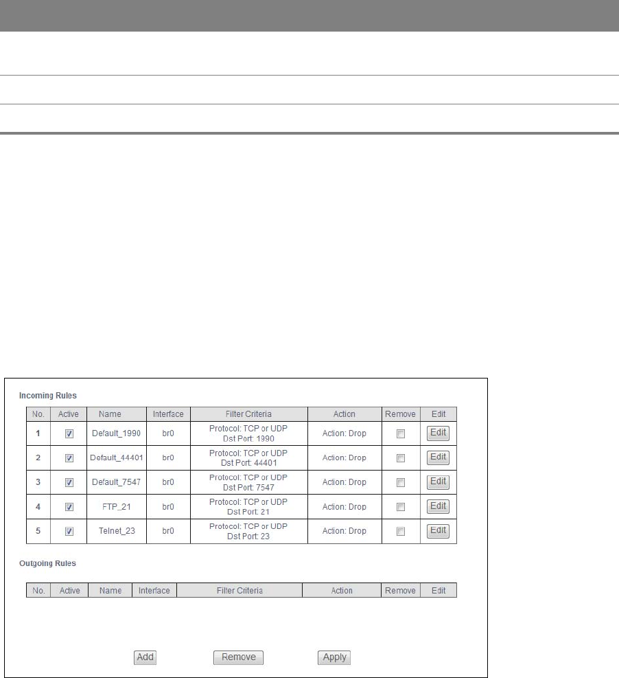
Chapter 7 Firewall 74
7.2 Firewall Rules
The ordering of your rules is very important as rules are applied in turn.
Click Advanced Setup > Firewall > Rules to display the following screen. This screen lists the
configured incoming or outgoing firewall rules. Note the order in which the rules are listed.
The firewall rules that you configure here take priority over the general firewall action
settings in the General screen.
Figure 43 Firewall Rules
Default
Action
Specify whether the firewall silently discards packets (Drop) or allows the passage of packets
(Permit).
Back Click Back to return to the previous screen.
Apply Click Apply to save your customized settings and exit this screen.
Table 39 Default Policy (continued)
LABEL DESCRIPTION

Chapter 7 Firewall 75
Table 40 Firewall Rules
LABEL DESCRIPTION
Incoming/
Outgoing
Rules
The following fields summarize the rules you have created that apply to traffic traveling
in the selected packet direction.
No. This is your firewall rule number. The ordering of your rules is important as rules are
applied in turn.
Active This field displays whether a firewall rule is turned on or not. Select the check box to
enable the rule. Clear the check box to disable the rule.
Name This displays the name of the rule.
Interface This displays the LAN or WAN interface(s) to which this rule is applied.
Filter Criteria This displays the filtering criteria, such as the source or destination IP addresses and
subnet mask to which this rule applies.
Action This displays whether the firewall silently discards packets (Drop), discards packets and
sends an ICMP message to the sender (Reject) or allows the passage of packets
(Permit).
Remove Select entries and click the Remove button to delete them.
Edit Click the Edit button to go to the screen where you can edit the rule.
Add Click Add to create a new rule.
Apply Click Apply to save your changes back to the Router.
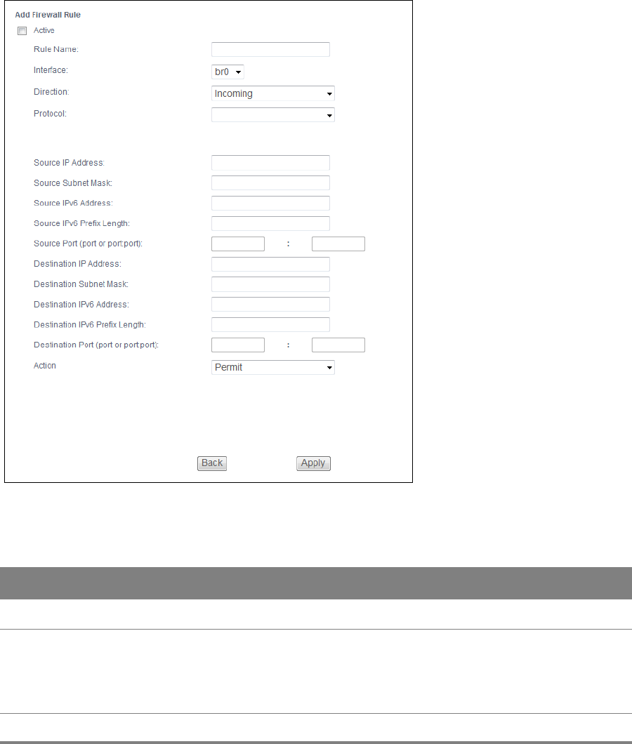
Chapter 7 Firewall 76
7.2.1 Firewall Rules Configuration
In the Firewall Rules screen, click Add or click a rule’s Edit button to display this screen and refer to
the following table for information on the labels.
Figure 44 Firewall Rules: Add
Table 41 Firewall Rules: Add
LABEL DESCRIPTION
Active Select this check box to enable the rule.
Rule Name Enter a descriptive name of up to 16 printable English keyboard characters,
including spaces.
To add a firewall rule, you need to configure at least one of the following fields
(except the Interface field).
Interface Select an interface on the Router to which this rule applies.

Chapter 7 Firewall 77
7.3 MAC Filtering
Click Advanced Setup > Firewall > MAC Filtering to allow or block wireless and LAN clients access
to the Router.
Direction Select a direction of travel of packets for which you want to configure the firewall
rule.
Protocol Select the IP protocol (TCP, UDP or ICMP) and enter the protocol (service type)
number in the port field.
Source IP Address Enter the source IP address in dotted decimal notation.
Source Subnet
Mask
Enter the source subnet mask.
Source IPv6
Address
Enter the source IPv6 address in dotted decimal notation.
Source IPv6 Prefix
Length
Enter the IPv6 prefix length for the source IPv6 address.
The IPv6 prefix length specifies how many most significant bits (starting from the
left) in the address compose the network address. This field displays the bit number
of the IPv6 subnet mask.
Source Port Enter the single port number or the range of port numbers of the source.
Destination IP
Address
Enter the destination IP address in dotted decimal notation.
Destination
Subnet Mask
Enter the destination subnet mask.
Destination IPv6
Address
Enter the destination IPv6 address in dotted decimal notation.
Destination IPv6
Prefix Length
Enter the IPv6 prefix length for the destination IPv6 address.
The IPv6 prefix length specifies how many most significant bits (starting from the
left) in the address compose the network address. This field displays the bit number
of the IPv6 subnet mask.
Destination Port Enter the single port number or the range of port numbers of the destination.
Action Use the drop-down list box to select whether to discard (Drop), deny and send an
ICMP message to the sender of (Reject) or allow the passage of (Permit) packets
that match this rule.
Reject Type If you select Reject, specify the type of ICMP message to send to the sender.
Back Click Back to return to the previous screen.
Apply Click Apply to save your customized settings and exit this screen.
Table 41 Firewall Rules: Add (continued)
LABEL DESCRIPTION
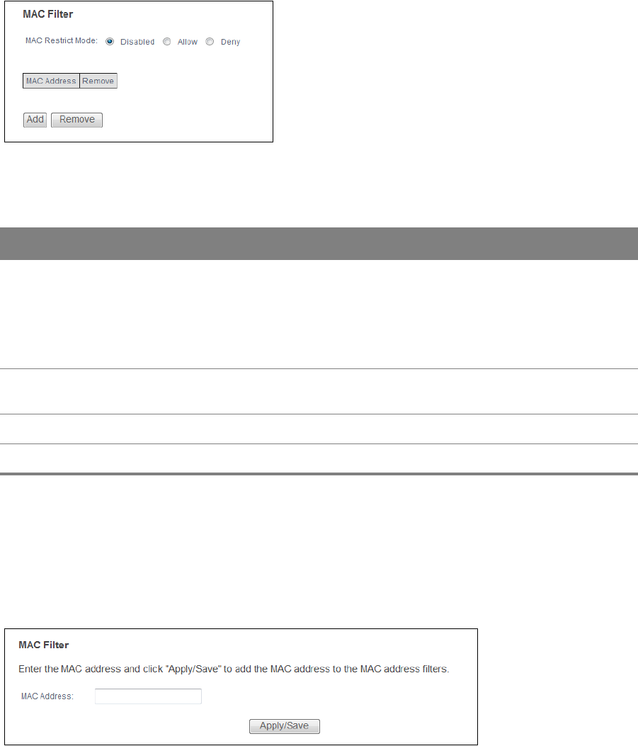
Chapter 7 Firewall 78
Every Ethernet device has a unique MAC (Media Access Control) address. The MAC address is
assigned at the factory and consists of six pairs of hexadecimal characters, for example,
00:A0:C5:00:00:02. You need to know the MAC address of the devices to configure this screen.
Figure 45 MAC Filtering
The following table describes the labels in this menu.
Table 42 MAC Filtering
LABEL DESCRIPTION
MAC Restrict
Mode
Select Disabled to turn off MAC address filtering.
Select Allow to have the Router permit access from the listed wireless and LAN client
MAC addresses and block access from MAC addresses not in the list.
Select Deny to have the Router block access from the listed wireless and LAN client MAC
addresses and allow access from MAC addresses not in the list.
MAC Address These are the MAC addresses of LAN devices. Enter the MAC addresses in a valid MAC
address format, that is, six hexadecimal character pairs, for example, 12:34:56:78:9a:bc.
Apply Click Apply to save your changes.
Cancel Click Cancel to restore your previously saved settings.
7.3.1 MAC Filtering Add
Click Advanced Setup > Firewall > MAC Filtering > Add to add a MAC address to the MAC
Filtering screen’s list of wireless and LAN clients access to the Router.
Figure 46 MAC Filtering Add

Chapter 7 Firewall 79
The following table describes the labels in this menu.
Table 43 MAC Filtering Add
LABEL DESCRIPTION
MAC Address Enter the MAC address in a valid MAC address format, that is, six hexadecimal character
pairs, for example, 12:34:56:78:9a:bc.
Apply/Save Click this button to save your changes.

8
Chapter
Chapter 8 Parental Control 80
CHAPTER 8
Chapter 8 Parental Control
8.1 Time Restriction
Click Advanced Setup > Parental Control > Time Restriction to configure access time schedules
for specific users.
Figure 47 Time Restriction
Table 44 Time Restriction
LABEL DESCRIPTION
Username This is the name of the user whose access the rule controls.
MAC This is the MAC address of the LAN or wireless device whose access the rule controls.
Mon ~ Sun This shows an “x” for every day of the week the schedule applies to.
Start This shows the beginning of the access blocking time.
Stop This shows the end of the access blocking time.
Remove Select entries and click the Remove button to delete them.
Add Click this to add a new entry.

Chapter 8 Parental Control 81
8.1.1 Add a Time Restriction Rule
Click Add in the Time Restriction screen to add a new rule. Use this screen to configure a restricted
access schedule.
Figure 48 Time Restriction: Add
Table 45 Time Restriction: Add
LABEL DESCRIPTION
Username Specify the name of the user whose access the rule controls.
Browser's MAC
Address
Select this to create the rule for the MAC address of the device with the browser you
are using to configure the Router.
'Browser's MAC Address' automatically displays the MAC address of the LAN device
where the browser is running.
This is the MAC address of the LAN or wireless device whose access the rule controls.
Other MAC Address Select this and enter the MAC address of another LAN device. To find out the MAC
address of a Windows based PC, go to the command window and type "ipconfig /
all".
Days of the week Select check boxes for the days that you want the Router to perform parental
control.
Start Blocking Time Enter the time in 24-hour format to begin blocking access.
End Blocking Time Enter the time in 24-hour format to stop blocking access.
Apply/Save Click this button to save your changes.
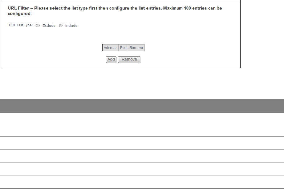
Chapter 8 Parental Control 82
8.2 URL Filter
Click Advanced Setup > Parental Control > Url Filter to use the Url Filter screen to block or allow
access to specific web sites.
Figure 49 URL Filter
Table 46 URL Filter
LABEL DESCRIPTION
URL List Type Select Exclude to block access to the URLs in the list and allow access to other URLs.
Select Include to allow access to the URLs in the list and block access to other URLs.
Address This shows the website address (URL) to which the entry applies.
Port This shows the port number for the URL list entry.
Remove Select entries and click the Remove button to delete them.
Add Click this to add a new entry.
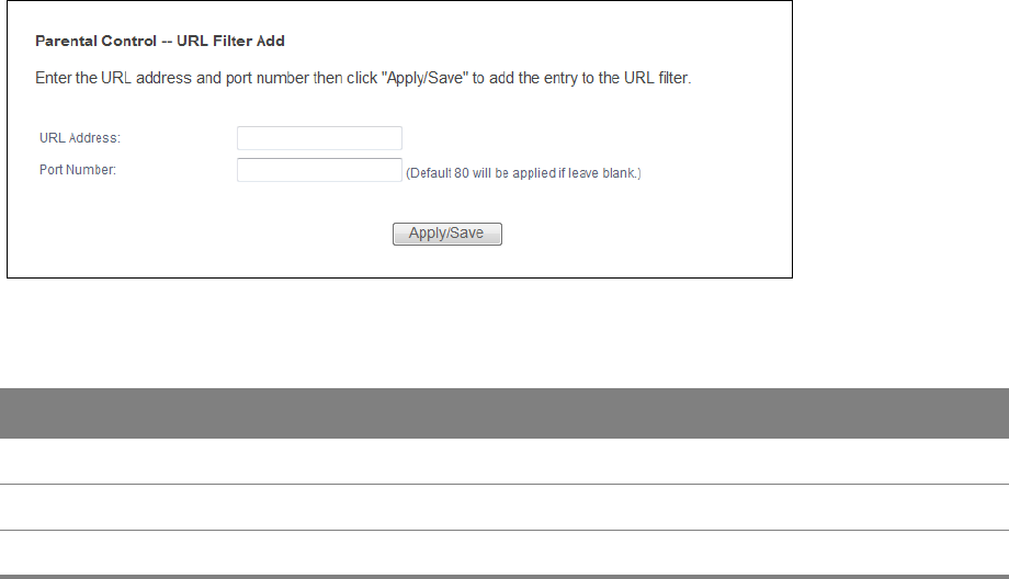
Chapter 8 Parental Control 83
8.2.1 Add a URL Filter Rule
Click Add in the URL Filter screen to add a new entry. Use this screen to configure a URL filtering
setting to control access to certain web sites.
Figure 50 URL Filter: Add
Table 47 URL Filter: Add
LABEL DESCRIPTION
URL Address Specify a web site or URL to which to filter access.
Port Number Specify the port number if you need to control access to one other than 80.
Apply/Save Click this button to save your changes.
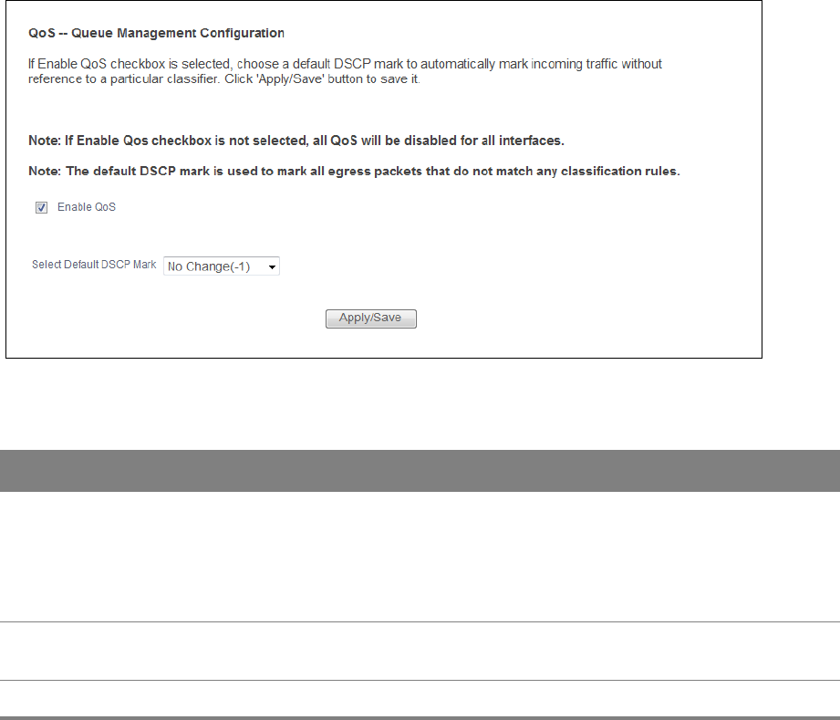
9
Chapter
Chapter 9 Quality of Service (QoS) 84
CHAPTER 9
Chapter 9 Quality of Service (QoS)
9.1 QoS General
Click Advanced Setup > Quality of Service to enable or disable QoS, set the bandwidth, and select
to have the Router automatically assign priority to upstream traffic according to the IP precedence
or packet length.
Figure 51 QoS General
Table 48 QoS General
LABEL DESCRIPTION
Enable QoS Select the check box to turn on QoS to improve your network performance.
You can give priority to traffic that the Router forwards out through the WAN interface.
Give high priority to voice and video to make them run more smoothly. Similarly, give
low priority to many large file downloads so that they do not reduce the quality of other
applications.
Select Default
DSCP Mark
Set the default DSCP (DiffServ Code Point) value for outgoing packets that do not match
any classification rules.
Apply/Save Click this button to save your changes.
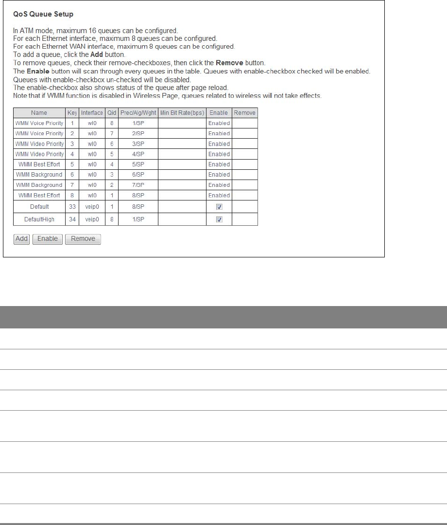
Chapter 9 Quality of Service (QoS) 85
9.2 Queue Setup
Click Advanced Setup > Quality of Service > Queue Setup to use the Queue Setup screen to
configure QoS queue assignment.
Figure 52 Queue Setup
Table 49 Queue Setup
LABEL DESCRIPTION
Name This shows the descriptive name of this queue.
Key This is the queue’s index number.
Interface This shows the name of the Router’s interface through which traffic in this queue passes.
Qid This shows the priority of this queue for the interface.
Prec/Alg/Wght This displays the queue’s default precedence, queue management algorithm, and
weighted round robin weight. SP is strict priority.
Min Bit Rate
(bps)
This shows the minimum transmission rate for traffic in this queue.
Enable This shows whether the queue is active or not. For queues with a check box, select it and
click the Enable button to turn them on. Clear the check box to turn a queue off.
Remove Select entries and click the Remove button to delete them.

Chapter 9 Quality of Service (QoS) 86
9.2.1 Add a QoS Queue
Click the Add button in the QoS Queue screen to configure a new queue.
Figure 53 Queue Setup: Add
Add Click Add to create a new queue.
Enable Select disabled entries and click the Enable button to activate them.
Table 49 Queue Setup (continued)
LABEL DESCRIPTION
Table 50 Queue Setup: Add
LABEL DESCRIPTION
Name Enter the descriptive name of this queue.
Enable Select to enable or disable this queue.
Interface Select the interface of this queue.
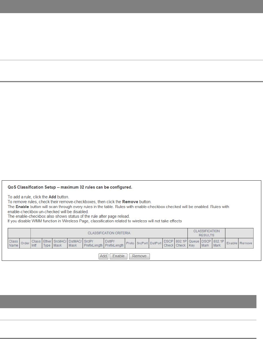
Chapter 9 Quality of Service (QoS) 87
9.3 Class Setup
Click Advanced Setup > Quality of Service > Class Setup to configure QoS classifiers. A classifier
groups traffic into data flows according to specific criteria such as the source address, destination
address, source port number, destination port number or incoming interface.
You can give different priorities to traffic that the Router forwards out through the WAN interface.
Give high priority to voice and video to make them run more smoothly. Similarly, give low priority to
many large file downloads so that they do not reduce the quality of other applications.
Figure 54 QoS Classification Setup
Queue
Precedence
Select a queue precedence level (from 1 to 8) to configure for the selected interface. The
smaller the number, the higher the priority level. Traffic assigned to higher priority
queues gets through faster while traffic in lower priority queues is dropped if the
network is congested. If the queue precedence level already has a queue scheduler
configured, it displays after the precedence level.
The Router uses strict priority to service queues with different precedences.
Minimum Rate This displays for GPON interface queues.
Specify the minimum transmission rate (in Kbps) allowed for traffic on this queue.
Table 50 Queue Setup: Add (continued)
LABEL DESCRIPTION
Table 51 QoS Classification Setup
LABEL DESCRIPTION
Class Name This displays the name of the classifier rule.
Order This displays the rule’s place in the list of classifier rules. The Router checks traffic
against classifiers in order until it matches one.

Chapter 9 Quality of Service (QoS) 88
CLASSIFICATION
CRITERIA
These fields show the criteria specified in the classifier rule. For example the
interface from which traffic of this class comes and the source MAC address of
traffic that matches this classifier.
Class Intf This displays the ingress interface to which the classifier applies.
Ether Type This displays the type of Ethernet frames to which the classifier applies.
SrcMAC/ Mask This displays the source MAC and network mask of traffic to which the classifier
applies.
DstMAC/ Mask This displays the destination MAC and network mask of traffic to which the classifier
applies.
SrcIP/
PrefixLength
This displays the source IP address and prefix length of traffic to which the classifier
applies.
DstIP/
PrefixLength
This displays the destination IP address and prefix length of traffic to which the
classifier applies.
Proto This displays the protocol of traffic to which the classifier applies.
SrcPort This displays the source port of traffic to which the classifier applies.
DstPort This displays the destination port of traffic to which the classifier applies.
DSCP Check This displays the DSCP mark of traffic to which the classifier applies.
802.1P Check This displays the IEEE 802.1p priority level of traffic to which the classifier applies.
CLASSIFICATION
RESULTS
These fields show the changes the classifier rule applies to matching traffic.
Queue Key This displays the number of the queue to which the Router adds traffic that matches
this classifier.
DSCP Mark This displays the DSCP mark the Router adds to traffic that matches this classifier.
802.1P Mark This displays the IEEE 802.1p priority level the Router assigns to traffic that matches
this classifier.
Enable Select an entry’s Enable option and click the Enable button to turn it on.
Remove Select an entry’s Remove option and click the Remove button to delete it.
Add Click this button to create a new classifier rule.
Table 51 QoS Classification Setup (continued)
LABEL DESCRIPTION
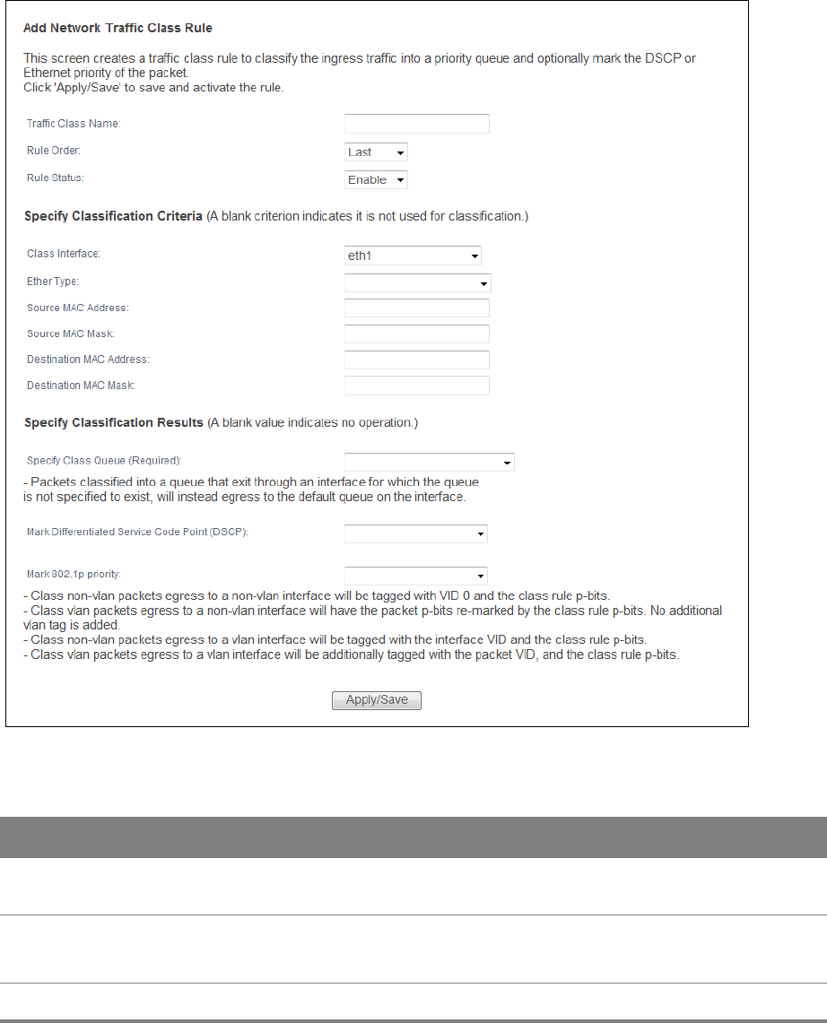
Chapter 9 Quality of Service (QoS) 89
9.3.1 Add QoS Class
Click Add in the Class Setup screen to configure a new classifier.
Figure 55 Add QoS Class
Table 52 Add QoS Class
LABEL DESCRIPTION
Traffic Class Name Enter a descriptive name of up to 15 printable English keyboard characters, not
including spaces.
Rule Order Select this classifier’s place in the list of classifiers.
Select Last to put this rule in the back of the classifier list.
Rule Status Turn this classifier on or off.

Chapter 9 Quality of Service (QoS) 90
Specify Classification
Criteria
Configure these fields to identify the traffic to which the class applies. The fields
available vary depending on the selected interface and Ether type. Leave a field
blank to not apply that criterion.
Class Interface Select the ingress interface to which the classifier applies.
Ether Type Select the predefined application (IP, ARP, IPv6, PPPoE discovery, PPPoE session,
8865, 8866, or IEEE 802.1q) to which the classifier applies. The list of types available
to choose from varies depending on the selected interface.
Source MAC Address Enter a MAC address to apply the classifier to packets from that MAC address.
Source MAC Mask Type the mask for the specified MAC address to determine which bits a packet’s
MAC address should match.
Enter “f” for each bit of the specified source MAC address that the traffic’s MAC
address should match. Enter “0” for the bit(s) of the matched traffic’s MAC address,
which can be of any hexadecimal character(s). For example, if you set the MAC
address to 00:13:49:00:00:00 and the mask to ff:ff:ff:00:00:00, a packet with a MAC
address of 00:13:49:12:34:56 matches this criteria.
Destination MAC
Address
Enter a MAC address to apply the classifier to packets destined for that MAC
address.
Destination MAC
Mask
Type the mask for the specified MAC address to determine which bits a packet’s
MAC address should match.
Enter “f” for each bit of the specified source MAC address that the traffic’s MAC
address should match. Enter “0” for the bit(s) of the matched traffic’s MAC address,
which can be of any hexadecimal character(s). For example, if you set the MAC
address to 00:13:49:00:00:00 and the mask to ff:ff:ff:00:00:00, a packet with a MAC
address of 00:13:49:12:34:56 matches this criteria.
Source IP Address[/
Mask]
Select this and enter an IP address to apply the classifier to packets from that IP
address. You can also include a source subnet mask.
Vendor Class ID
(DHCP Option 60)
Select this and enter the Vendor Class Identifier (Option 60) of the matched traffic,
such as the type of the hardware or firmware.
User Class ID DHCP
option 77
Select this and enter a string that identifies the user’s category or application type in
the matched DHCP packets.
Destination IP
Address[/Mask]
Enter an IP address to apply the classifier to packets destined for that IP address.
You can also include a destination subnet mask.
Differentiated
Service Code Point
(DSCP) Check
Select a DSCP mark of traffic to which to apply the classifier.
802.1p Priority
Check
This field displays when you set the Ether Type field to 8021Q.
Select the IEEE 802.1p priority level (between 0 and 7) of traffic to which to apply the
classifier. "0" is the lowest priority level and "7" is the highest.
Table 52 Add QoS Class (continued)
LABEL DESCRIPTION

Chapter 9 Quality of Service (QoS) 91
Specify Classification
Results
Configure these fields to change traffic that matches the classifier. The fields
available vary depending on the selected interface, Ether type, and sometimes on
the selected class queue. Leave a field blank to not apply that type of change.
Specify Class Queue Select the queue to which to add traffic that matches this classifier.
Mark Differentiated
Service Code Point
(DSCP):
Select the DSCP mark to add to traffic that matches this classifier. Use Auto marking
to automatically apply a DSCP mark according to the type of traffic. Use default to
leave the DSCP mark unchanged.
Mark 802.1p priority Select the IEEE 802.1p priority level to assign to traffic that matches this classifier.
Set Rate Limit Set the rate limit to apply to traffic that matches this classifier.
Apply/Save Click this button to save your changes.
Table 52 Add QoS Class (continued)
LABEL DESCRIPTION
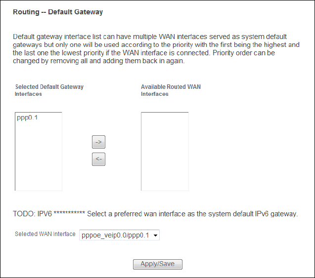
10
Chapter
Chapter 10 Routing 92
CHAPTER 10
Chapter 10 Routing
10.1 Default Gateway
Click Advanced Setup > Routing > Default Gateway to open the Default Gateway screen. Use
this screen to select WAN interfaces to serve as system default gateways.
Figure 56 Default Gateway
Move the WAN interfaces to serve as system default gateways from Available Routed WAN
Interfaces to Selected Default Gateway Interfaces.
Use the Selected WAN Interface field to select the preferred WAN interface to server as the
Router’s default IPv6 gateway.
Click Apply/Save to save your changes.
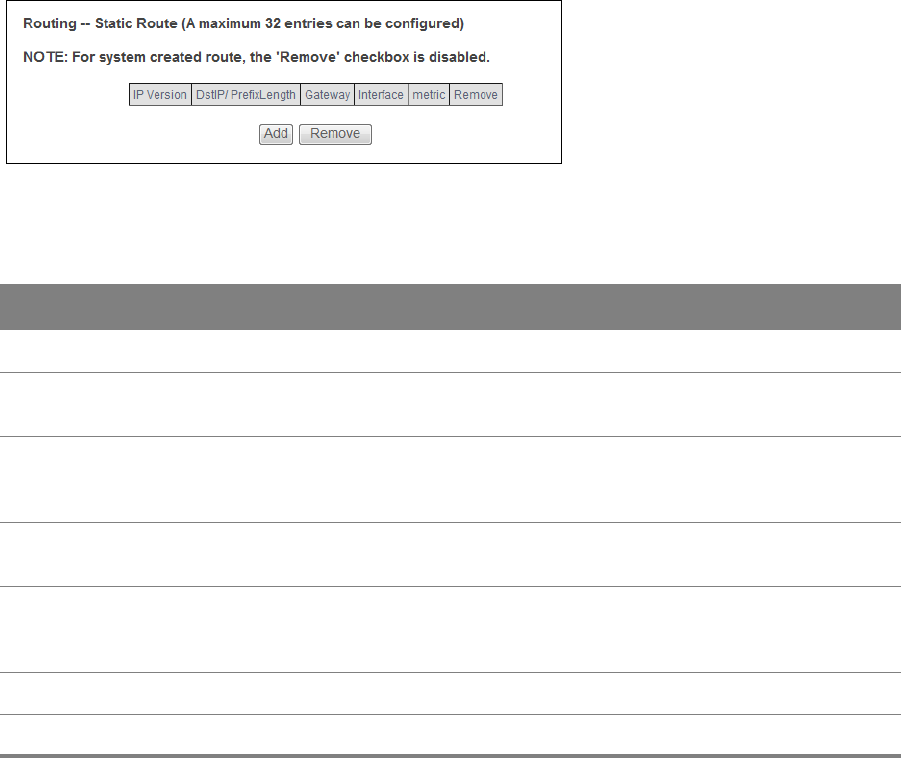
Chapter 10 Routing 93
10.2 Static Route
Click Advanced Setup > Routing > Static Route to view and configure the static route rules on the
Router.
Figure 57 Static Route
Table 53 Static Route
LABEL DESCRIPTION
IP Version This displays whether the entry uses IPv4 or IPv6.
DstIP/
PrefixLength
This specifies the IP network address and prefix length of the final destination. Routing
is always based on network number.
Gateway This is the IP address of the gateway. The gateway is a router or switch on the same
network segment as the device's LAN or WAN port. The gateway helps forward packets
to their destinations.
Interface This is the interface this static route uses to forward traffic for the listed destination
address.
metric The metric represents the "cost of transmission". A router determines the best route for
transmission by choosing a path with the lowest "cost". The smaller the number, the
lower the "cost".
Remove Select entries and click the Remove button to delete them.
Add Click this to configure a new static route.
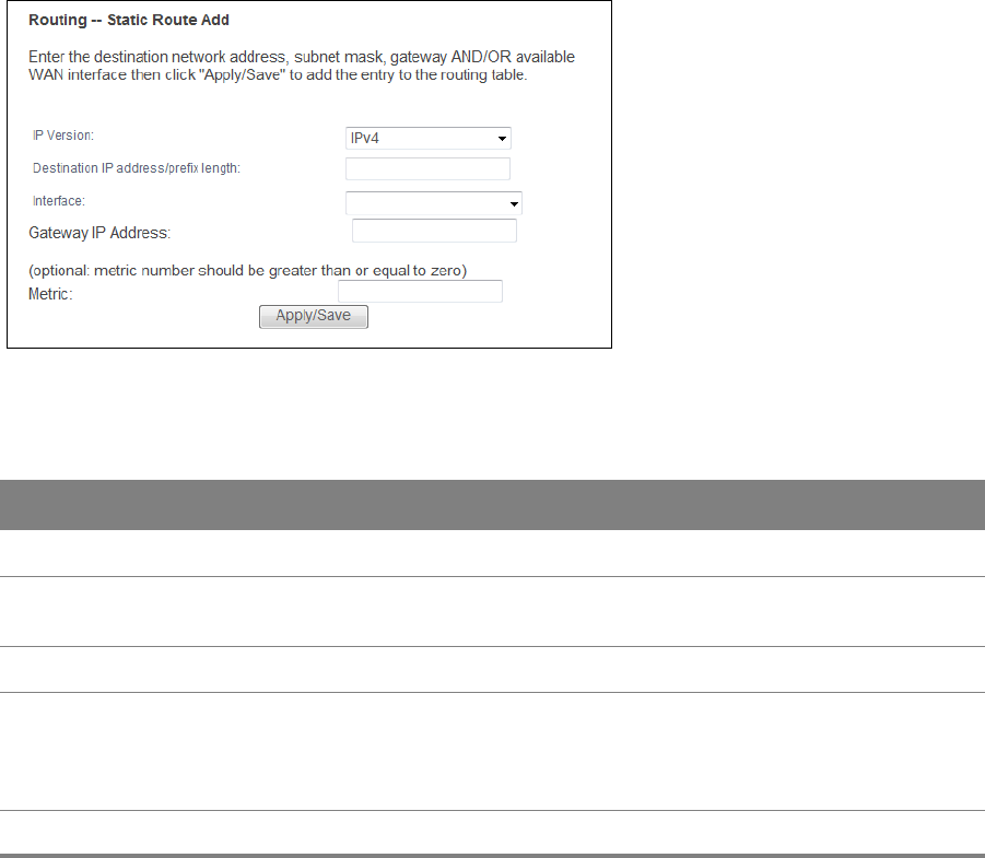
Chapter 10 Routing 94
10.2.1 Add Static Route
Use this screen to add a static route. Click Add in the Static Route screen to display the following
screen.
Figure 58 Static Route: Add
Table 54 Static Route: Add
LABEL DESCRIPTION
IP Version Select whether your IP type is IPv4 or IPv6.
Destination IP address/
prefix length
Enter the IPv4 or IPv6 address and network length of the final destination.
Interface Select the interface through which this static route sends traffic.
Gateway IP Address Enter the IP address of the gateway when you configure a static route that
uses an IP-based interface (such as IPoE, IPoA, or LAN). The gateway is a
router or switch on the same network segment as the device's LAN or WAN
port. The gateway helps forward packets to their destinations.
Apply/Save Click this button to save your changes.
10.3 Policy Routing
Traditionally, routing is based on the destination address only and the Router takes the shortest
path to forward a packet. Policy routing allows the Router to override the default routing behavior
and alter the packet routing based on the policy defined by the network administrator. Policy-based
routing is applied to outgoing packets, prior to the normal routing.
You can use source-based policy routing to direct traffic from different users through different
connections or distribute traffic among multiple paths for load sharing.
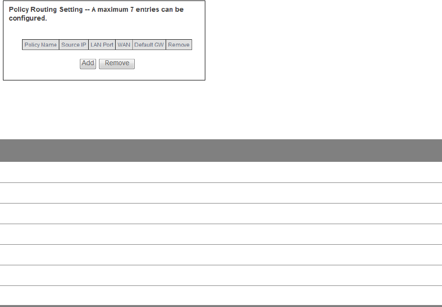
Chapter 10 Routing 95
Use the Policy Routing screen to view and configure routing policies on the Router. Click Advanced
Setup > Routing > Policy Routing to open the following screen.
Figure 59 Policy Routing
Table 55 Policy Routing
LABEL DESCRIPTION
Policy Name This displays the name of the rule.
Source IP This displays the source IP address.
LAN Port This displays the source LAN port number.
WAN This displays the WAN interface through which the traffic is routed.
Default GW This displays the default gateway IP address the route uses.
Remove Select entries and click the Remove button to delete them.
Add Click this to create a new policy routing rule.
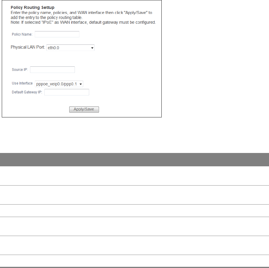
Chapter 10 Routing 96
10.3.1 Add Policy Routing
Click Add in the Policy Routing screen to open the following screen. Use this screen to configure
the required information for a policy route.
Figure 60 Policy Routing: Add
Table 56 Policy Routing: Add
LABEL DESCRIPTION
Policy Name Enter a descriptive name of printable English keyboard characters, not including
spaces.
Physical LAN
Port
Select the source LAN Ethernet port number.
Source IP Enter the source IP address.
Use Interface Select a WAN interface through which the traffic is sent. You must have the WAN
interface(s) already configured in the Broadband screens.
Default Gateway
IP
Enter the default gateway IP address the route uses.
Apply/Save Click this button to save your changes.
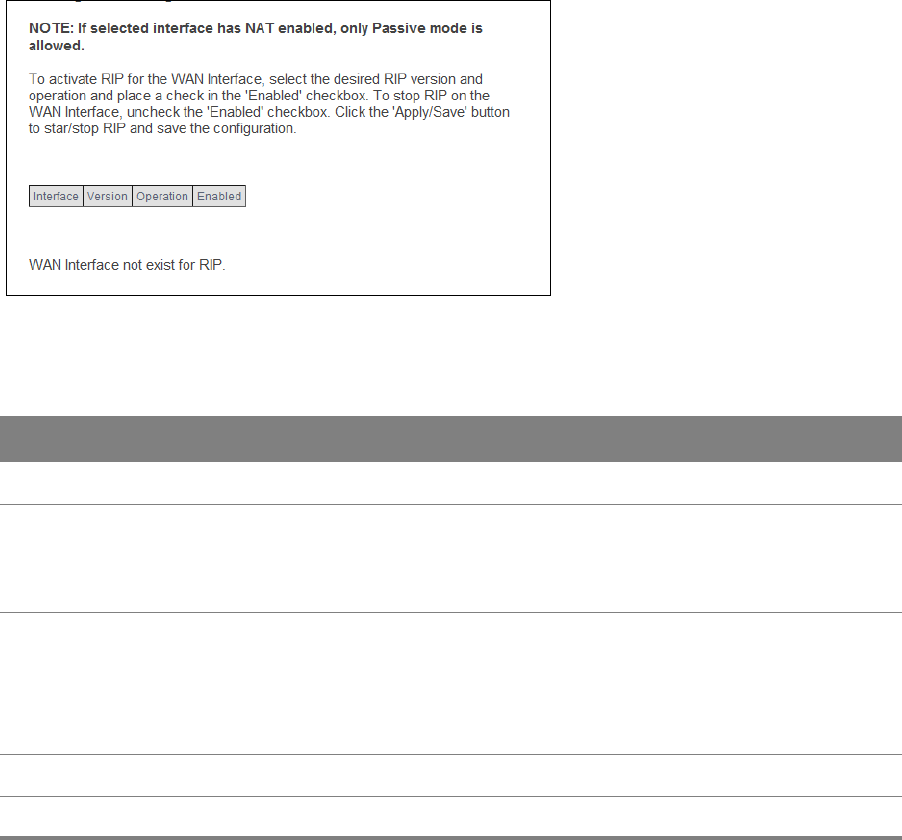
Chapter 10 Routing 97
10.4 RIP
Click Advanced Setup > Routing > RIP to open the RIP screen. Use this screen to configure RIP
settings. Routing Information Protocol (RIP, RFC 1058 and RFC 1389) allows a device to exchange
routing information with other routers.
Figure 61 RIP
Table 57 RIP
LABEL DESCRIPTION
Interface This is the name of the interface in which the RIP setting is used.
Version The RIP version controls the format and the broadcasting method of the RIP packets
that the Router sends (it recognizes both formats when receiving). RIP version 1 is
universally supported but RIP version 2 carries more information. RIP version 1 is
probably adequate for most networks, unless you have an unusual network topology.
Operation Select Passive to have the Router update the routing table based on the RIP packets
received from neighbors but not advertise its route information to other routers in this
interface.
Select Active to have the Router advertise its route information and also listen for
routing updates from neighboring routers.
Enabled Select the check box to activate the settings.
Apply/Save Click this button to save your changes.
11
Chapter
Chapter 11 DNS 98
CHAPTER 11
Chapter 11 DNS
11.1 DNS Server
DNS (Domain Name System) maps a domain name to its corresponding IP address and vice versa.
The DNS server is extremely important because without it, you must know the IP address of a
machine before you can access it.
Use this screen to view and configure DNS routes on the Router. Click Advanced Setup > DNS >
DNS Server to open this screen.
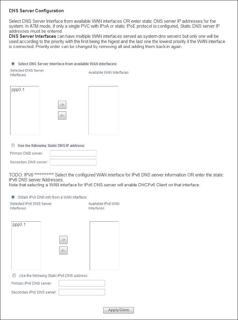
Chapter 11 DNS 99
Figure 62 DNS Server

Chapter 11 DNS 100
The following table describes the fields in this screen.
Table 58 DNS Server
LABEL DESCRIPTION
Select DNS Server
Interface from
available WAN
interfaces
Select this to have the Router get the DNS server addresses from one of the
Router’s WAN interfaces.
Selected DNS
Server Interfaces Select a WAN interface through which to get DNS server addresses.
You can select multiple WAN interfaces for the device to try. The Router tries the
WAN interfaces in the order listed and uses only the DNS server information of
the first WAN interface that connects; there is no backup WAN function. To
change the priority order remove them all and add them back in again.
Available WAN
Interfaces These are the WAN interfaces you can select from.
Use the following
Static DNS IP address
Select this to have the Router use the DNS server addresses you configure
manually.
Primary DNS
server Enter the first DNS server address assigned by the ISP.
Secondary DNS
server Enter the second DNS server address assigned by the ISP.
Obtain IPv6 DNS info
from a WAN interface
Select this to have the Router get the IPv6 DNS server addresses from the ISP
automatically.
Selected IPv6 DNS
Server Interfaces Select an IPv6 WAN interface through which you want to obtain the IPv6 DNS
related information.
Available IPv6
WAN Interfaces These are the IPv6 WAN interfaces you can select from.
Use the following
Static IPv6 DNS
address
Select this to have the Router use the IPv6 DNS server addresses you configure
manually.
Primary IPv6 DNS
server Enter the first IPv6 DNS server address assigned by the ISP.
Secondary IPv6
DNS server Enter the second IPv6 DNS server address assigned by the ISP.
Apply/Save Click this button to save your changes.
11.2 Dynamic DNS
Dynamic DNS allows you to update your current dynamic IP address with one or many dynamic
DNS services. You need to have registered a dynamic DNS account with www.dyndns.org. This is for
people with a dynamic IP from their ISP or DHCP server that would still like to have a domain name.

Chapter 11 DNS 101
Click Advanced Setup > DNS > Dynamic DNS to configure DDNS entries.
Figure 63 Dynamic DNS
The following table describes the fields in this screen.
Table 59 Dynamic DNS
LABEL DESCRIPTION
Hostname This displays the entry’s domain name.
Username This displays the entry’s user name.
Service This displays the entry’s Dynamic DNS service provider.
Interface This displays the interface the DDNS entry uses.
Remove Select entries and click the Remove button to delete them.
Add Click this to create a new DDNS entry.
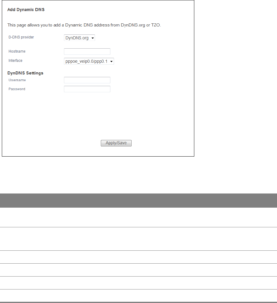
Chapter 11 DNS 102
11.2.1 Dynamic DNS Add
Use this screen to create a DDNS entry. Click the Dynamic DNS screen’s Add button to display the
following screen.
Figure 64 Dynamic DNS Add
The following table describes the fields in this screen.
Table 60 Dynamic DNS Add
LABEL DESCRIPTION
D-DNS
provider
Select your Dynamic DNS service provider from the drop-down list box.
Hostname Type the domain name assigned to your Router by your Dynamic DNS provider.
You can specify up to two host names in the field separated by a comma (",").
Interface Select the interface the DDNS entry uses.
Username Type your user name.
Password Type the password assigned to you.
Apply/Save Click this button to save your changes.

12
Chapter
Chapter 12 UPnP 103
CHAPTER 12
Chapter 12 UPnP
12.1 UPnP
Universal Plug and Play (UPnP) is a distributed, open networking standard that uses TCP/IP for
simple peer-to-peer network connectivity between devices. A UPnP device can dynamically join a
network, obtain an IP address, convey its capabilities and learn about other devices on the network.
In turn, a device can leave a network smoothly and automatically when it is no longer in use.
Use the UPnP screen to enable the UPnP feature on your Router. Click Advanced Setup > UPnP.
Figure 65 UPnP
Table 61 UPnP
LABEL DESCRIPTION
UPnP Select Enable to activate UPnP. Be aware that anyone could use a UPnP application to
open the web configurator's login screen without entering the Router's IP address
(although you must still enter the password to access the web configurator).
Apply/Save Click this button to save your changes.
Network Connections: My Network Places: Properties: Example
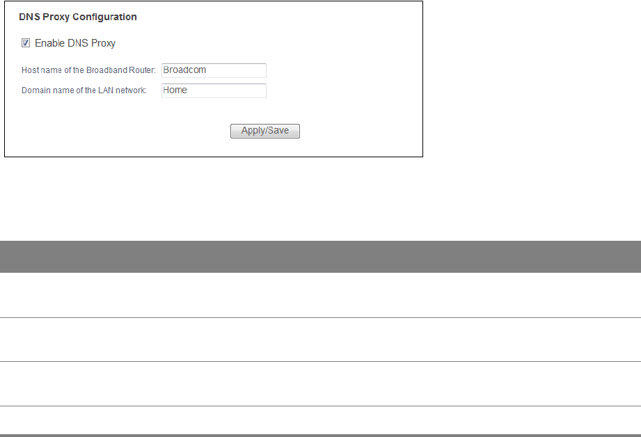
13
Chapter
Chapter 13 DNS Proxy 104
CHAPTER 13
Chapter 13 DNS Proxy
13.1 DNS Proxy
Use DNS Proxy to have the Router send its own address to the LAN clients for them to use as the
DNS server.
Click Advanced Setup > DNS Proxy to open the DNS Proxy screen.
Figure 66 DNS Proxy
Table 62 DNS Proxy
LABEL DESCRIPTION
Enable DNS Proxy Select this to have the Router send its own address to the LAN clients for them to use
as the DNS server.
Host name of the
Broadband Router
Enter a descriptive name for this Router.
Domain name of
the LAN network
Enter the domain name of the LAN network.
Apply/Save Click this button to save your changes.
Network Connections: My Network Places: Properties: Example
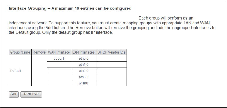
14
Chapter
Chapter 14 Interface Grouping 105
CHAPTER 14
Chapter 14 Interface Grouping
14.1 Interface Grouping
By default, all LAN and WAN interfaces on the Router are in the same group and can communicate
with each other. Create interface groups to have the Router assign the IP addresses in different
domains to different groups. Each group acts as an independent network on the Router. This lets
devices connected to an interface group’s LAN interfaces communicate through the interface
group’s WAN or LAN interfaces but not other WAN or LAN interfaces.
You can manually add a LAN interface to a new group. Alternatively, you can have the Router
automatically add the incoming traffic and the LAN interface on which traffic is received to an
interface group when its DHCP Vendor ID option information matches one listed for the interface
group.
Use the LAN screen to configure the private IP addresses the DHCP server on the Router assigns to
the clients in the default and/or user-defined groups. If you set the Router to assign IP addresses
based on the client’s DHCP Vendor ID option information, you must enable DHCP server and
configure LAN TCP/IP settings for both the default and user-defined groups. Click Advanced Setup
> Interface Grouping to open the following screen.
Figure 67 Interface Grouping

Chapter 14 Interface Grouping 106
The following table describes the fields in this screen.
Table 63 Interface Grouping
LABEL DESCRIPTION
Group Name This shows the descriptive name of the group.
Remove Select this check box and click the Remove button to delete the group from the Router.
WAN
Interface
This shows the WAN interfaces in the group.
LAN
Interfaces
This shows the LAN interfaces in the group.
DHCP Vendor
IDs
This shows the DHCP Vendor’s ID for the group.
Add Click this button to create a new group.
14.1.1 Interface Group Configuration
Click the Add button in the Interface Grouping screen to open the following screen. Use this
screen to create a new interface group.
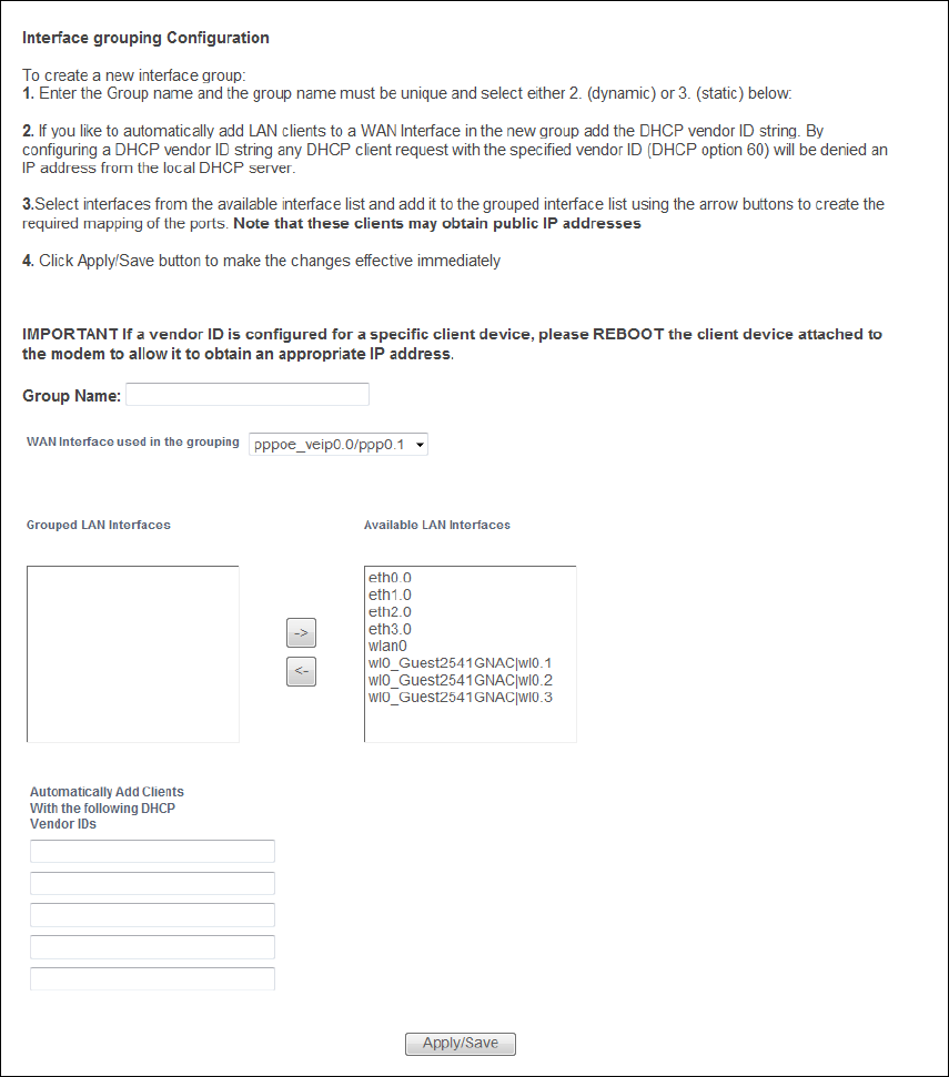
Chapter 14 Interface Grouping 107
An interface can belong to only one group at a time.
Figure 68 Interface Grouping: Add

Chapter 14 Interface Grouping 108
The following table describes the fields in this screen.
Table 64 Interface Grouping: Add
LABEL DESCRIPTION
Group Name Enter a name to identify this group. You can enter up to 30 characters. You can use
letters, numbers, hyphens (-) and underscores (_). Spaces are not allowed.
WAN
Interface
used in the
grouping
Select the WAN interface this group uses.
Select None to not add a WAN interface to this group.
Grouped LAN
Interfaces
Available LAN
Interfaces
Select one or more LAN interfaces (Ethernet LAN, HPNA or wireless LAN) in the
Available LAN Interfaces list and use the left arrow to move them to the Grouped LAN
Interfaces list to add the interfaces to this group.
To remove a LAN or wireless LAN interface from the Grouped LAN Interfaces, use the
right-facing arrow.
Automatically
Add Clients
With the
following
DHCP Vendor
IDs
If you want LAN clients to get public IP addresses, you can list their DHCP vendor IDs
here.
Apply/Save Click Apply/Save to save your changes back to the Router.
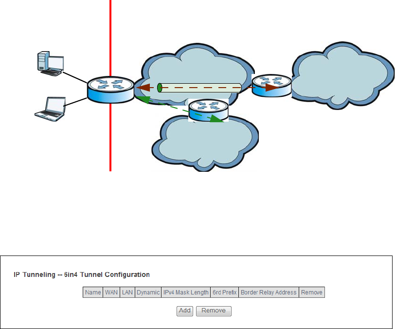
15
Chapter
Chapter 15 IP Tunnel 109
CHAPTER 15
Chapter 15 IP Tunnel
15.1 IPv6inIPv4 (6RD)
Use IPv6 Rapid Deployment (6RD) when the local network uses IPv6 and the ISP has an IPv4
network. When the Router has an IPv4 WAN address and is configured to IPv4 only, you can enable
6RD to encapsulate IPv6 packets in IPv4 packets to cross the ISP’s IPv4 network.
The Router generates a global IPv6 prefix from its IPv4 WAN address and tunnels IPv6 traffic to the
ISP’s Border Relay router (BR in the figure) to connect to the native IPv6 Internet. The local network
can also use IPv4 services. The Router uses it’s configured IPv4 WAN IP to route IPv4 traffic to the
IPv4 Internet.
Figure 69
ISP (IPv4) IPv6 Internet
IPv4
IPv6
BR
IPv6 in IPv4
IPv4 Internet
IPv4
+
LAN
- IPv6
- IPv4
WAN
- IPv4
- IPv6 in IPv4
IPv6 Rapid Deployment
Click Advanced Setup > IP Tunnel > IPv6inIPv4 to view and configure IPv6 through IPv4 tunneling.
This will encapsulate IPv6 packets in IPv4 packets so they can travel through IPv4 networks.
Figure 70 IPv6inIPv4

Chapter 15 IP Tunnel 110
Table 65 IPv6inIPv4
LABEL DESCRIPTION
Name This displays the IPv6 to IPv4 tunnel’s name.
WAN This displays the associated WAN interface.
LAN This displays the associated LAN interface.
Dynamic This displays the type of 6RD.
IPv4 Mask
Length
This displays the subnet mask number for the IPv4 network.
6rd Prefix This displays the IPv6 prefix for tunneling IPv6 traffic to the ISP’s border relay router and
connecting to the native IPv6 Internet.
Boarder
Relay
Address
This displays the relay server’s IPv4 address.
Remove Select an entry and click the Remove button to delete it.
Add Click this to add a new IPv6 through IPv4 tunnel.
15.1.1 IPv6inIPv4 Configuration
Click the Add button in the IPv6inIPv4 screen to add a new IPv6 through IPv4 tunnel entry.
Figure 71 IPv6inIPv4: Add

Chapter 15 IP Tunnel 111
Table 66 IPv6inIPv4: Add
LABEL DESCRIPTION
Tunnel
Name
Enter a descriptive name for the IPv6 through IPv4 tunnel.
Mechanism The current mechanism is set to 6RD to tunnel IPv6 traffic from the local network through
the ISP’s IPv4 network.
Associated
WAN
Interface
Select a WAN interface to associate with the IPv6 to IPv4 tunnel.
Associated
LAN
Interface
Select a LAN interface to associate with the IPv6 to IPv4 tunnel.
Manual/
Automatic
Select the 6RD type. Select Manual to set the 6RD type to static. Select Automatic to
have the Router detect it automatically through DHCP.
IPv4 Mask
Length
Enter the subnet mask number (1~32) for the IPv4 network.
6rd Prefix
with Prefix
Length
Enter an IPv6 prefix for tunneling IPv6 traffic to the ISP’s border relay router and
connecting to the native IPv6 Internet.
Border Relay
IPv4 Address
Specify the relay server’s IPv4 address in this field.
Apply/Save Click this button to save your changes.
15.2 IPv4inIPv6 (Dual Stack Lite)
Use DS-Lite (Dual Stack Lite) when local network computers use IPv4 and the ISP has an IPv6
network. When the Router has an IPv6 WAN address and is set to IPv6 only, you can enable Dual
Stack Lite to use IPv4 computers and services.
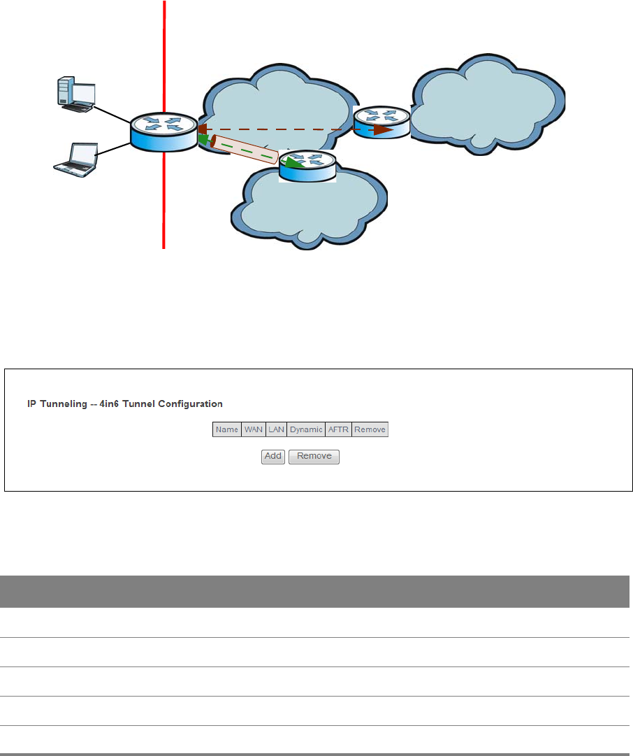
Chapter 15 IP Tunnel 112
The Router tunnels IPv4 packets inside IPv6 encapsulation packets to the ISP’s Address Family
Transition Router (AFTR in the graphic) to connect to the IPv4 Internet. The local network can also
use IPv6 services. The Router uses it’s configured IPv6 WAN IP to route IPv6 traffic to the IPv6
Internet.
Figure 72
ISP (IPv6) IPv6 Internet
IPv6
AFTR
IPv4 in IPv6
IPv4 Internet
IPv6 IPv4
+
LAN
- IPv6
- IPv4
WAN
- IPv6
- IPv4 in IPv6
Dual Stack Lite
Click Advanced Setup > IP Tunnel > IPv4inIPv6 to view and configure Dual Stack Lite to let local
computers use IPv4 through an ISP’s IPv6 network.
Figure 73 IPv4inIPv6
Table 67 IPv4inIPv6
LABEL DESCRIPTION
Name This displays the IPv4 through IPv6 tunnel’s name.
WAN This displays the associated WAN interface.
LAN This displays the associated LAN interface.
Dynamic This displays the type of 6RD.
AFTR This displays the transition router’s IPv6 address.
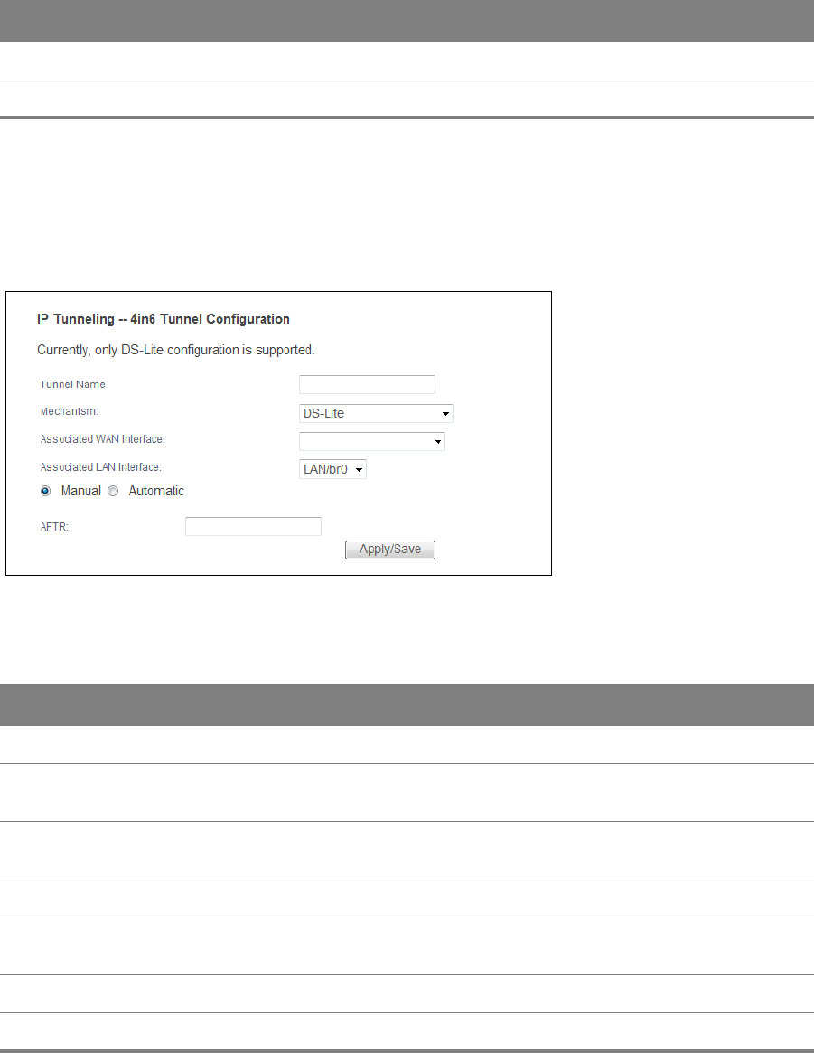
Chapter 15 IP Tunnel 113
15.2.1 IPv4inIPv6 Configuration
Click the Add button in the IPv4inIPv6 screen to add a new IPv6 through IPv4 tunnel entry.
Figure 74 IPv4inIPv6: Add
Table 68 IPv4inIPv6: Add
LABEL DESCRIPTION
Tunnel Name Enter a descriptive name for the IPv4 to IPv6 tunnel.
Mechanism The mechanism is set to DS-Lite to let local computers use IPv4 through an
ISP’s IPv6 network.
Associated WAN
Interface
Select a WAN interface to associate with the IPv4 to IPv6 tunnel.
Associated LAN Interface Select a LAN interface to associate with the IPv4 to IPv6 tunnel.
Manual/Automatic Select the 6RD type. Select Manual to set the 6RD type to static. Select
Automatic to have the Router detect it automatically through DHCP.
AFTR Specify the ISP’s Address Family Transition Router’s IPv6 address.
Apply/Save Click this button to save your changes.
Remove Select an entry and click the Remove button to delete it.
Add Click this to add a new IPv4 through IPv6 tunnel.
Table 67 IPv4inIPv6 (continued)
LABEL DESCRIPTION