Wyse Technology WT3720 User Manual
Wyse Technology Users Manual
UserManual.wiki
>
Wyse Technology
>
WT3720 User Manual
Users Manual
Navigation menu
Upload a User Manual
Namespaces
Wiki Guide
HTML
PDF
Info
Views
User Manual
Discussion / Help
Navigation
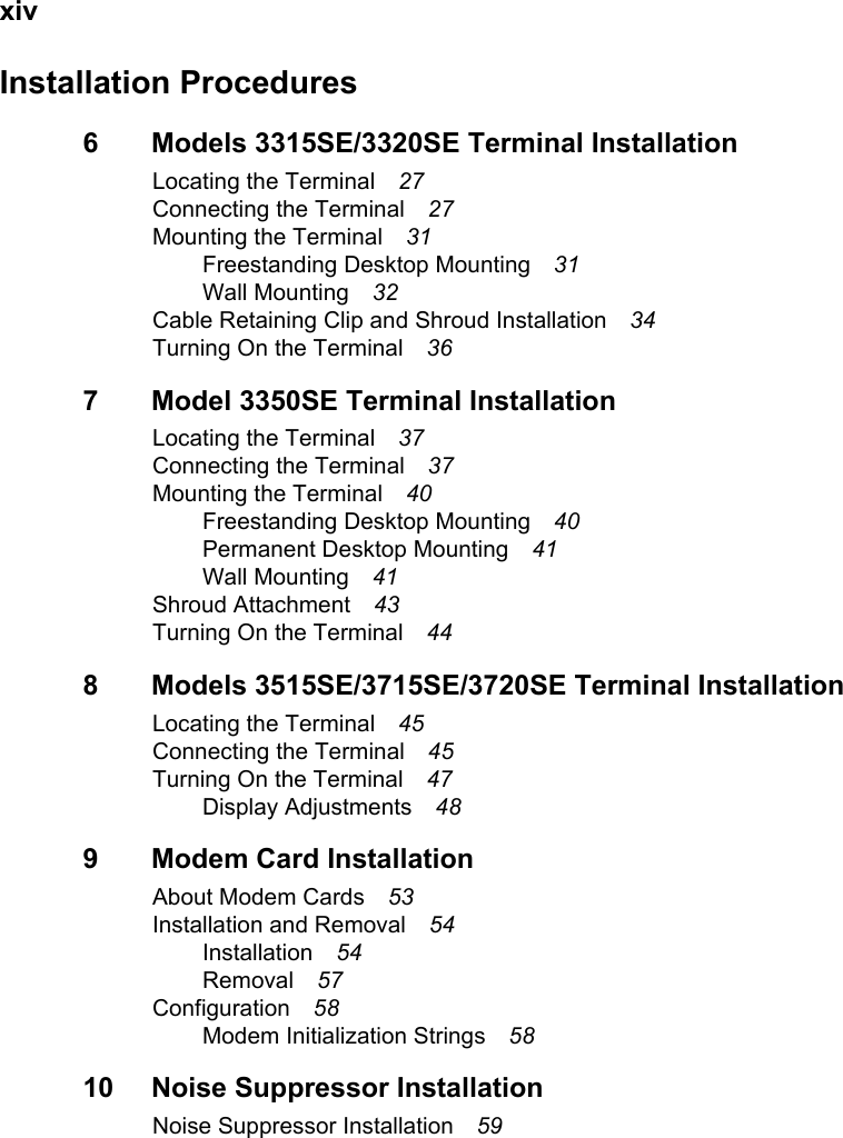
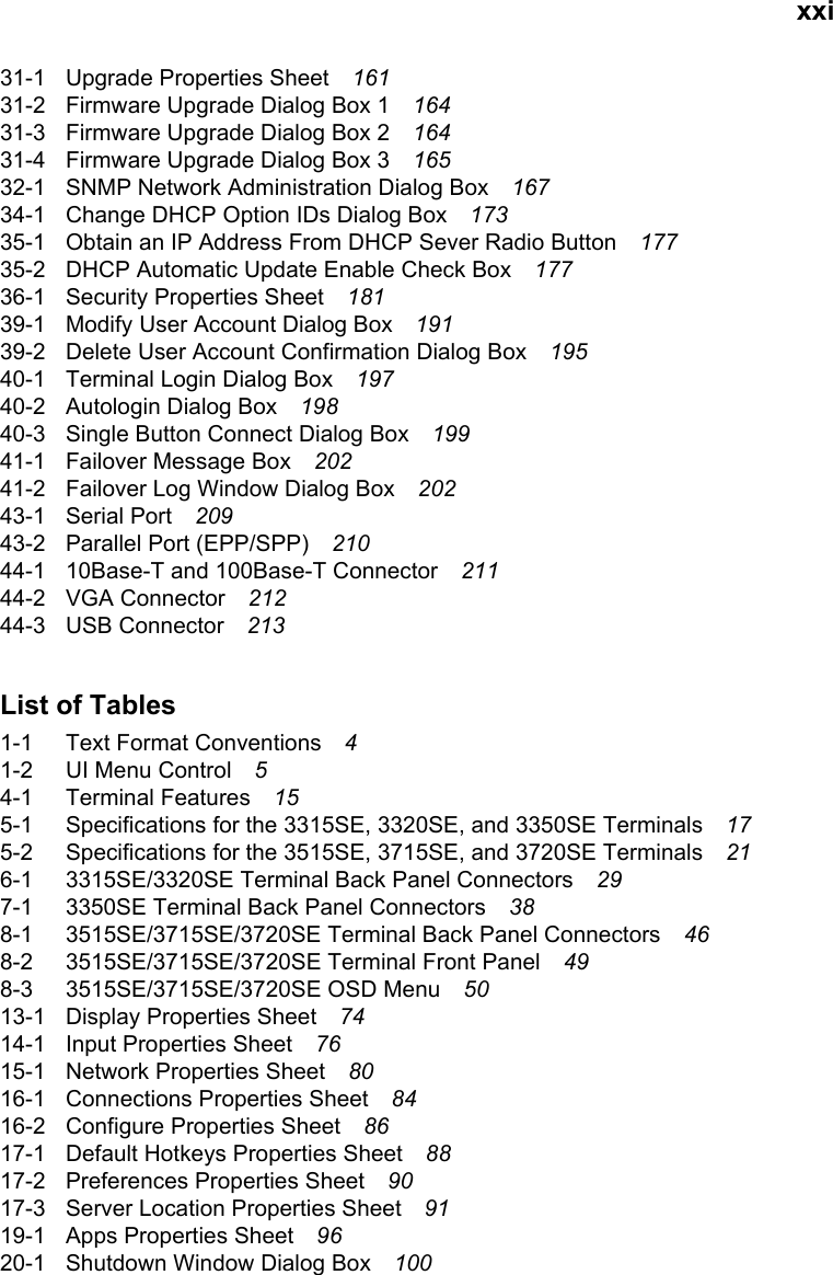


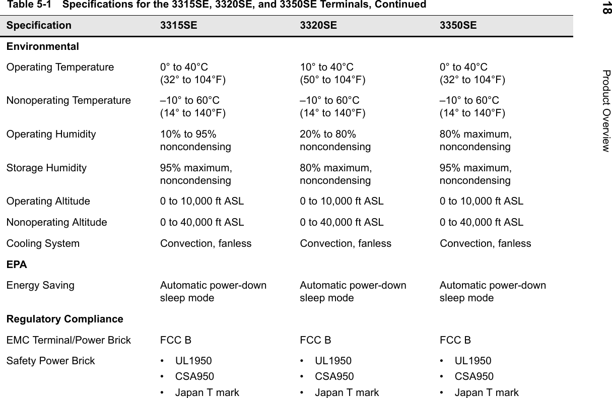

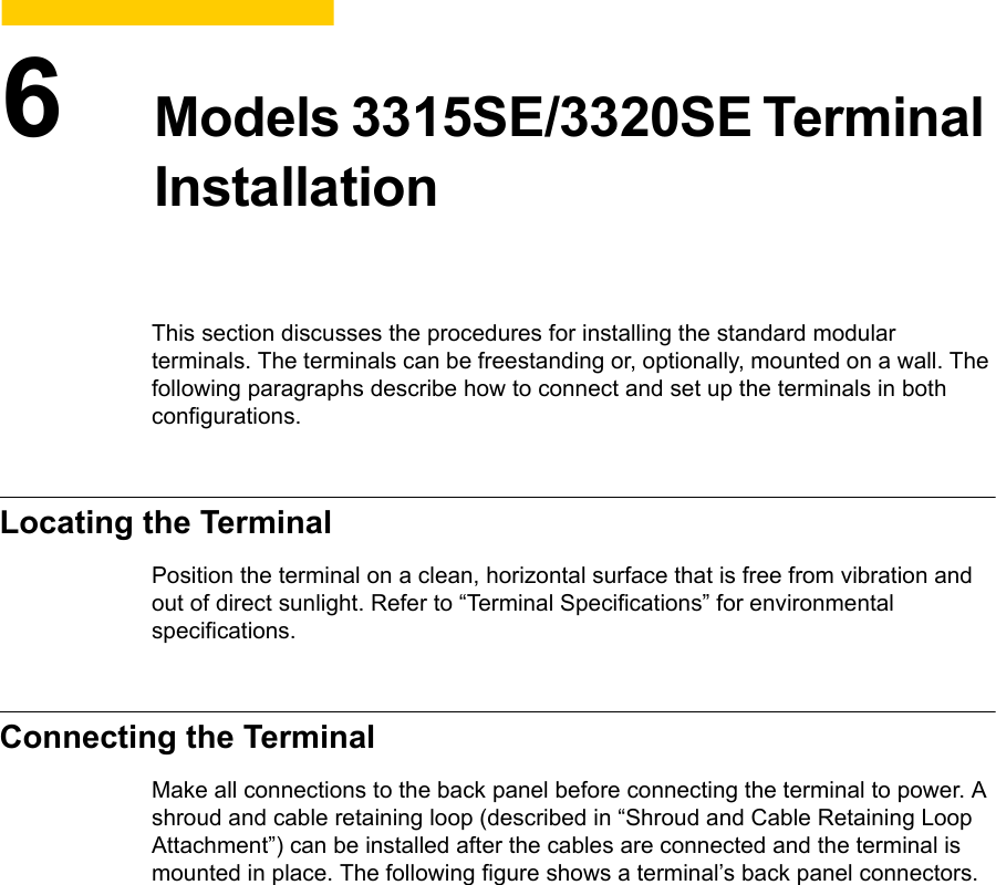
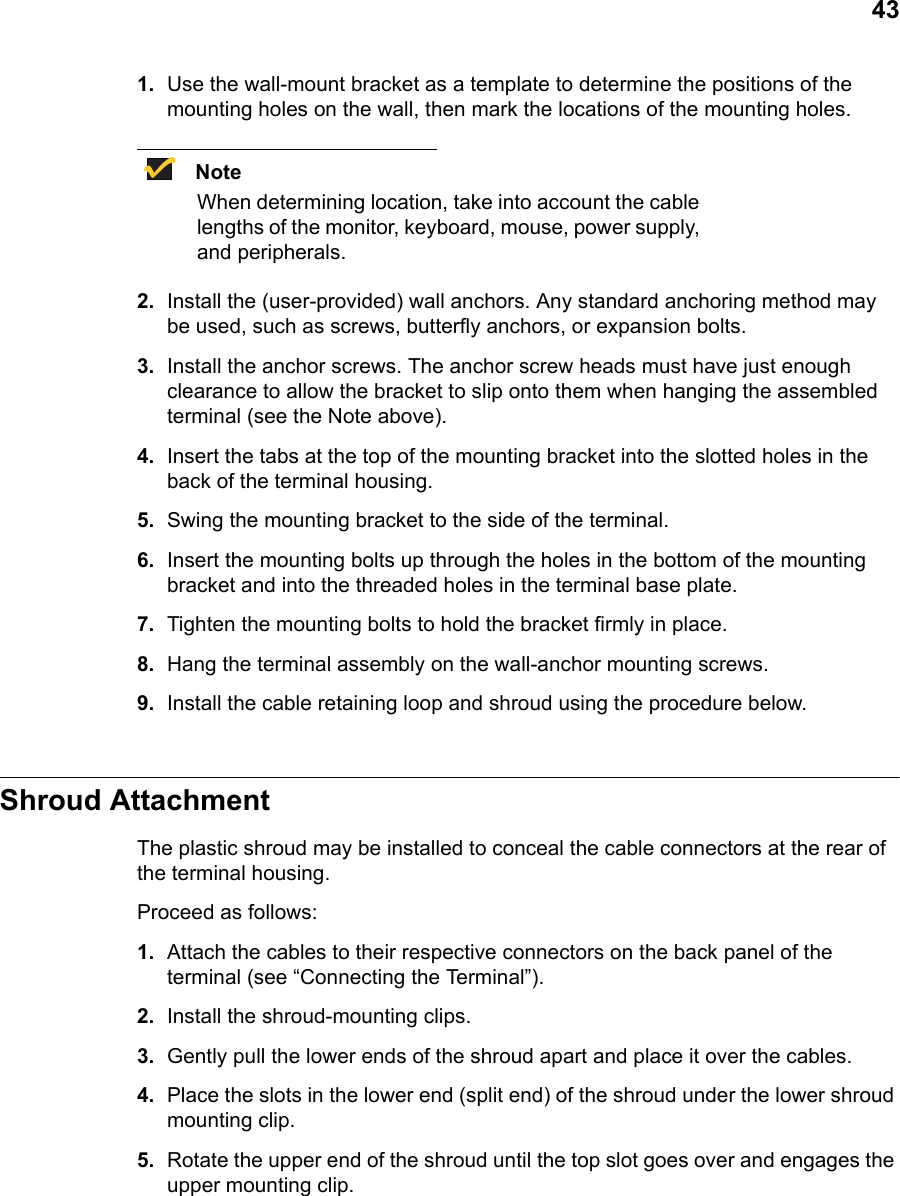
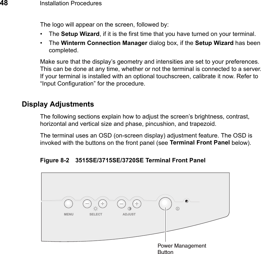
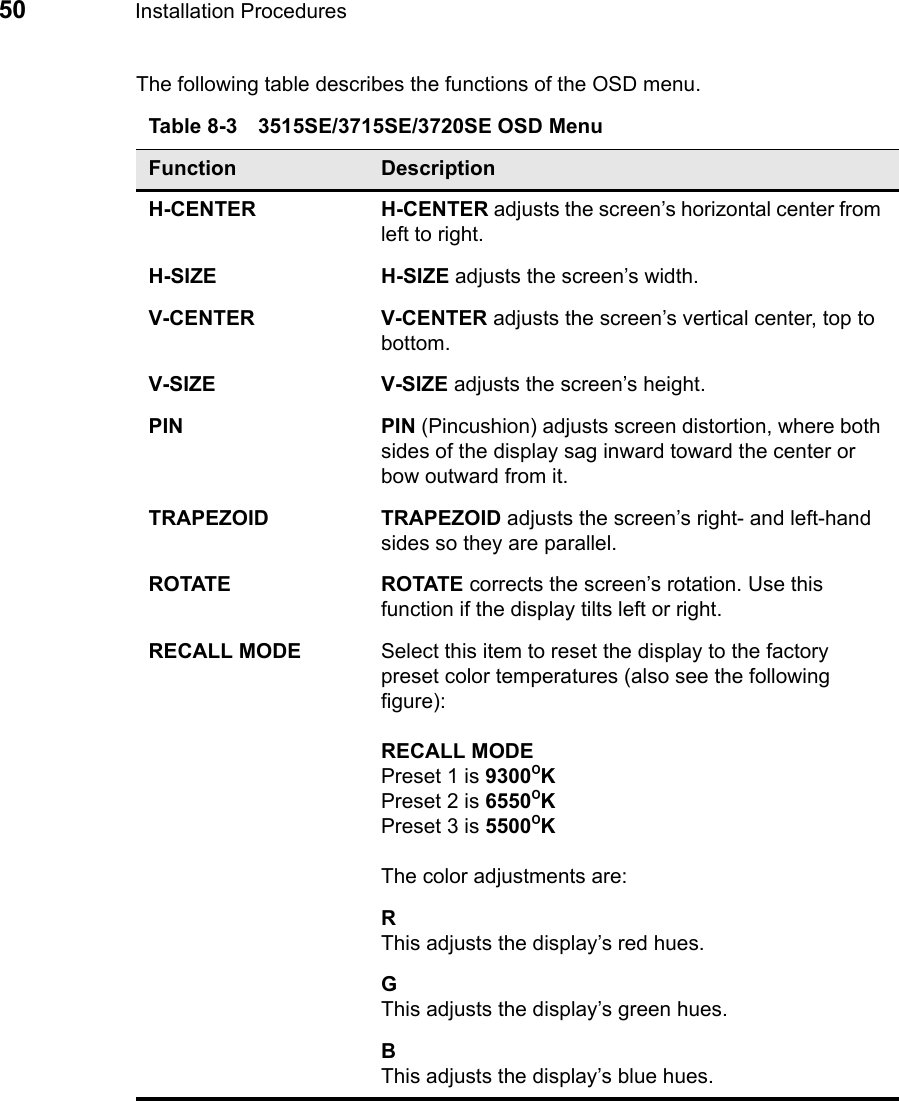
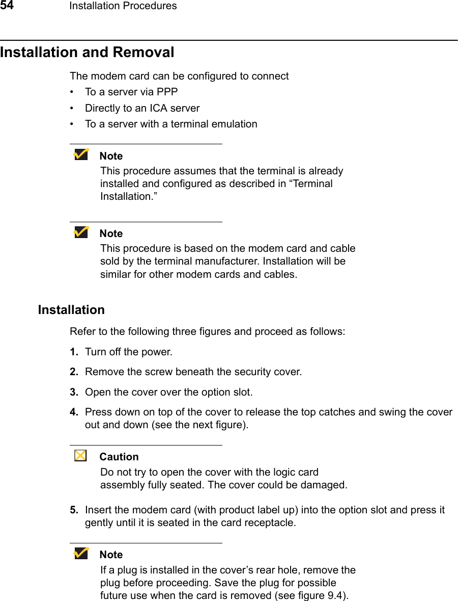
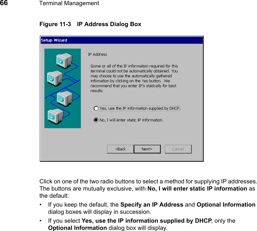
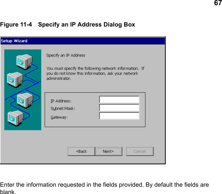
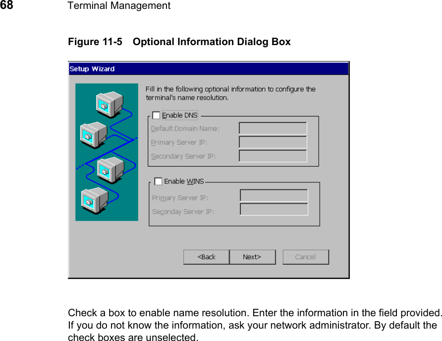
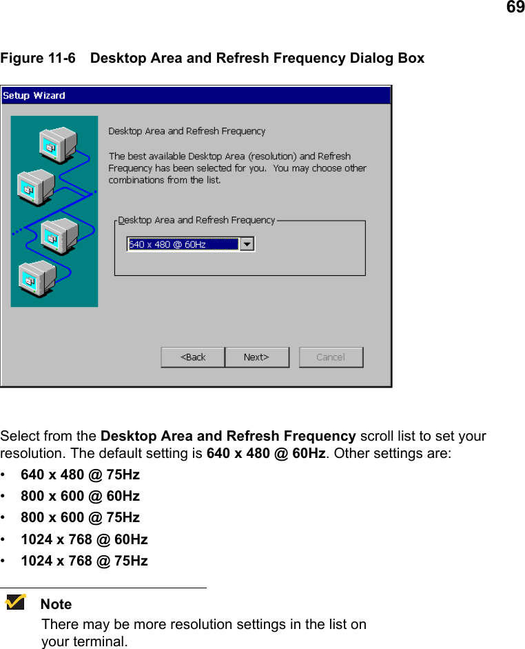
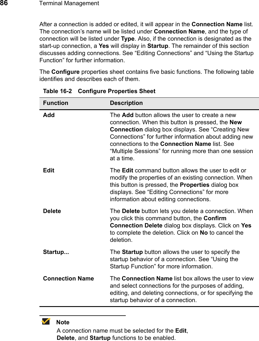
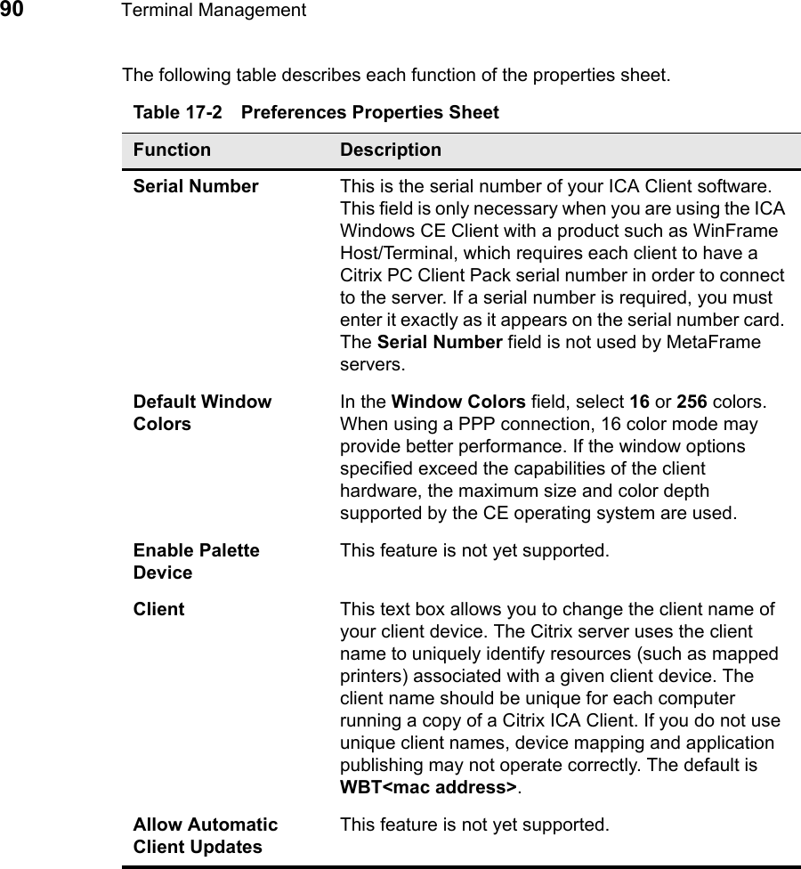
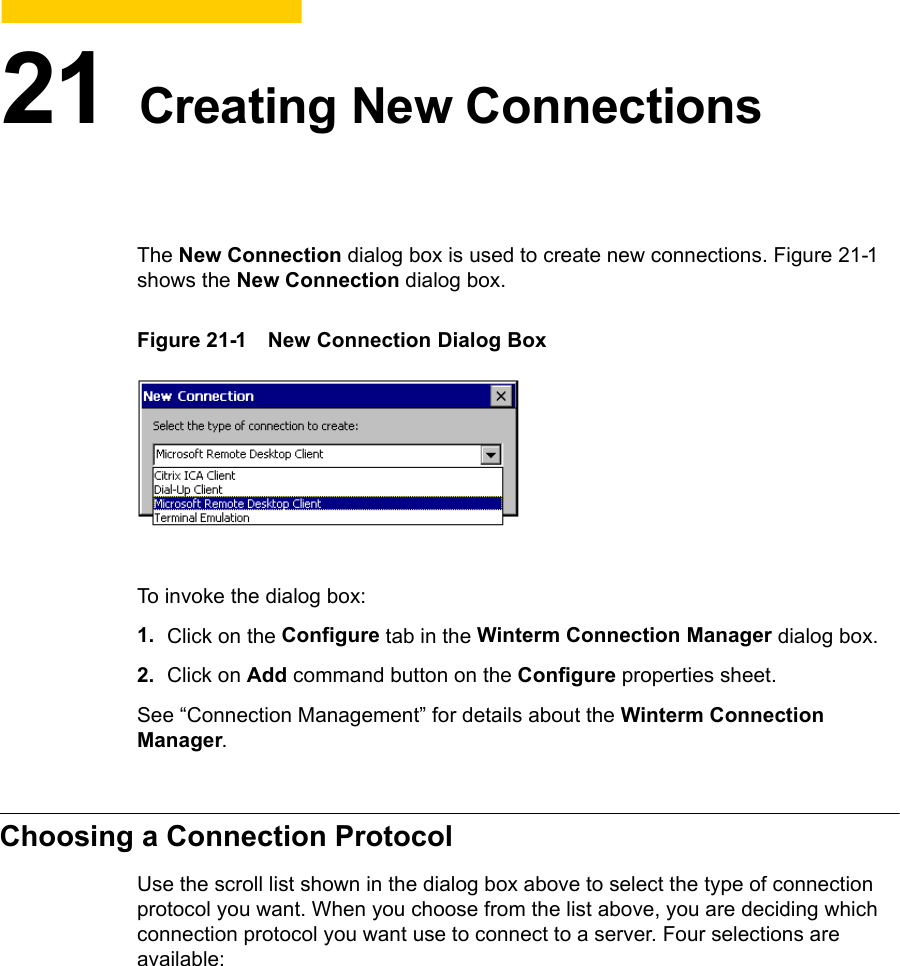
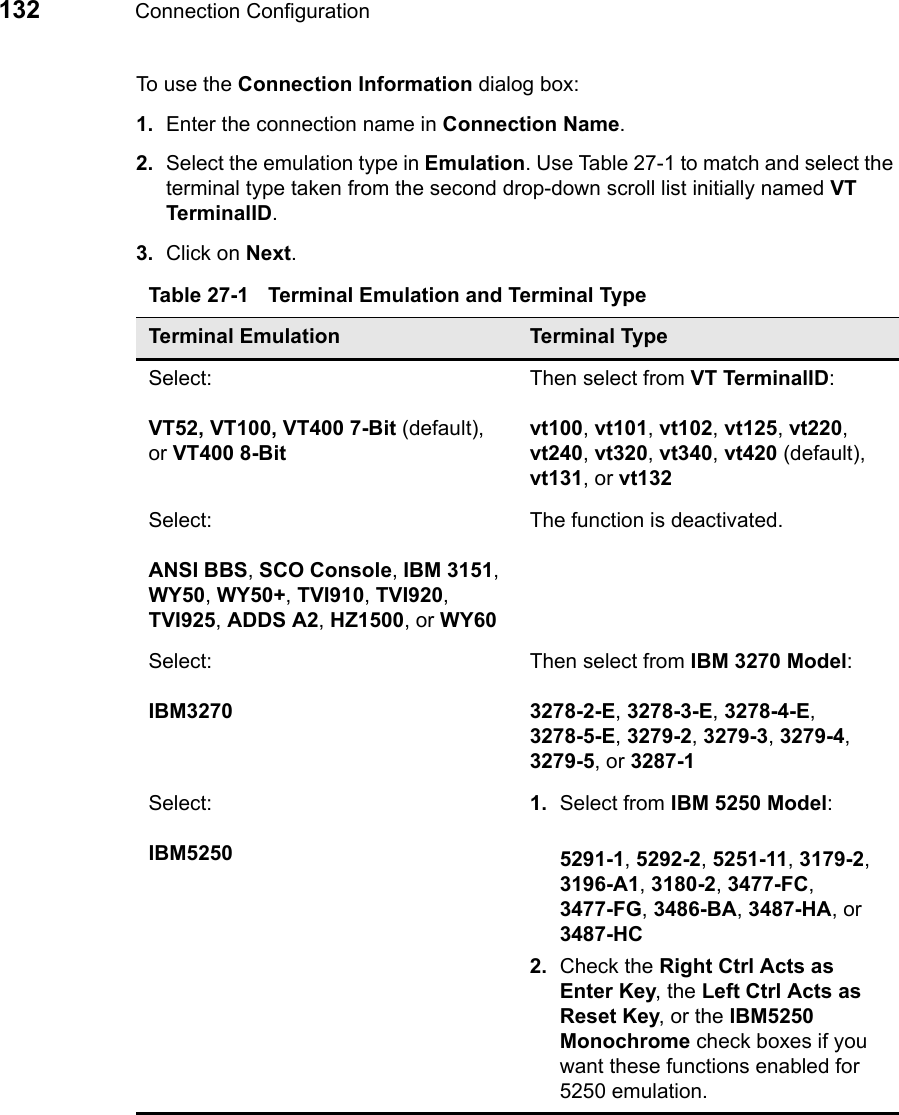
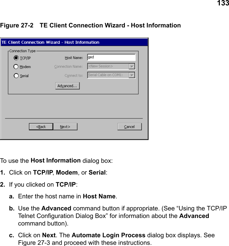
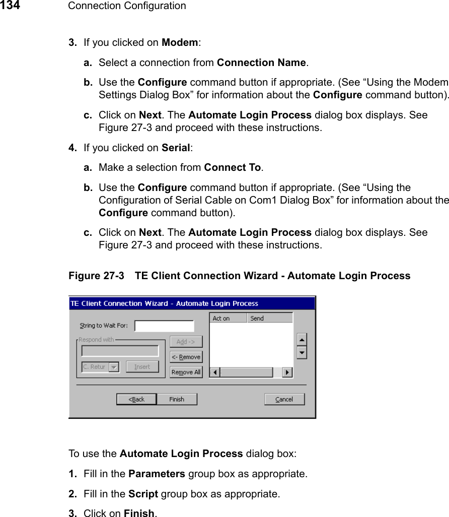
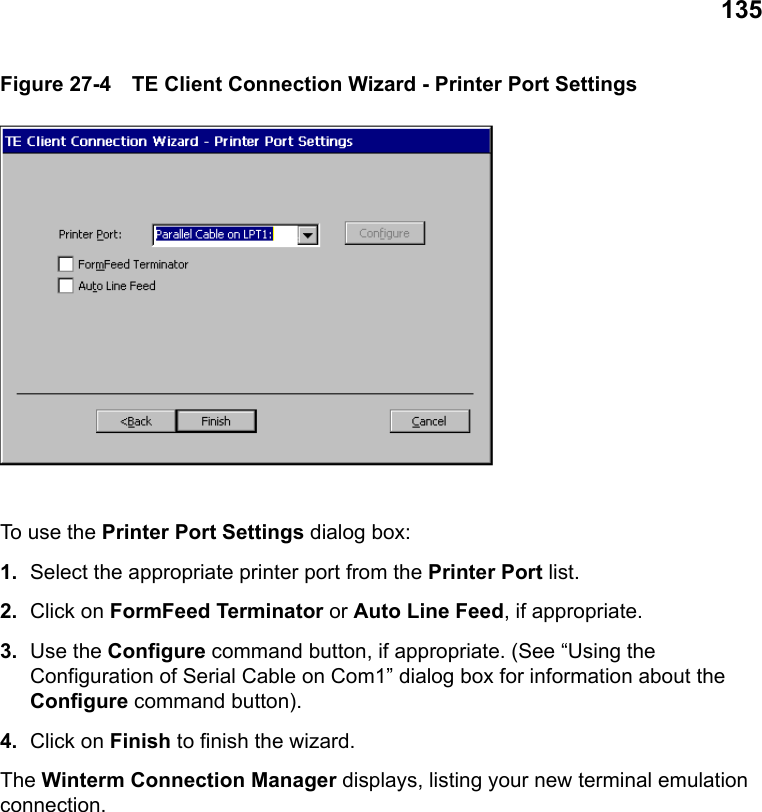
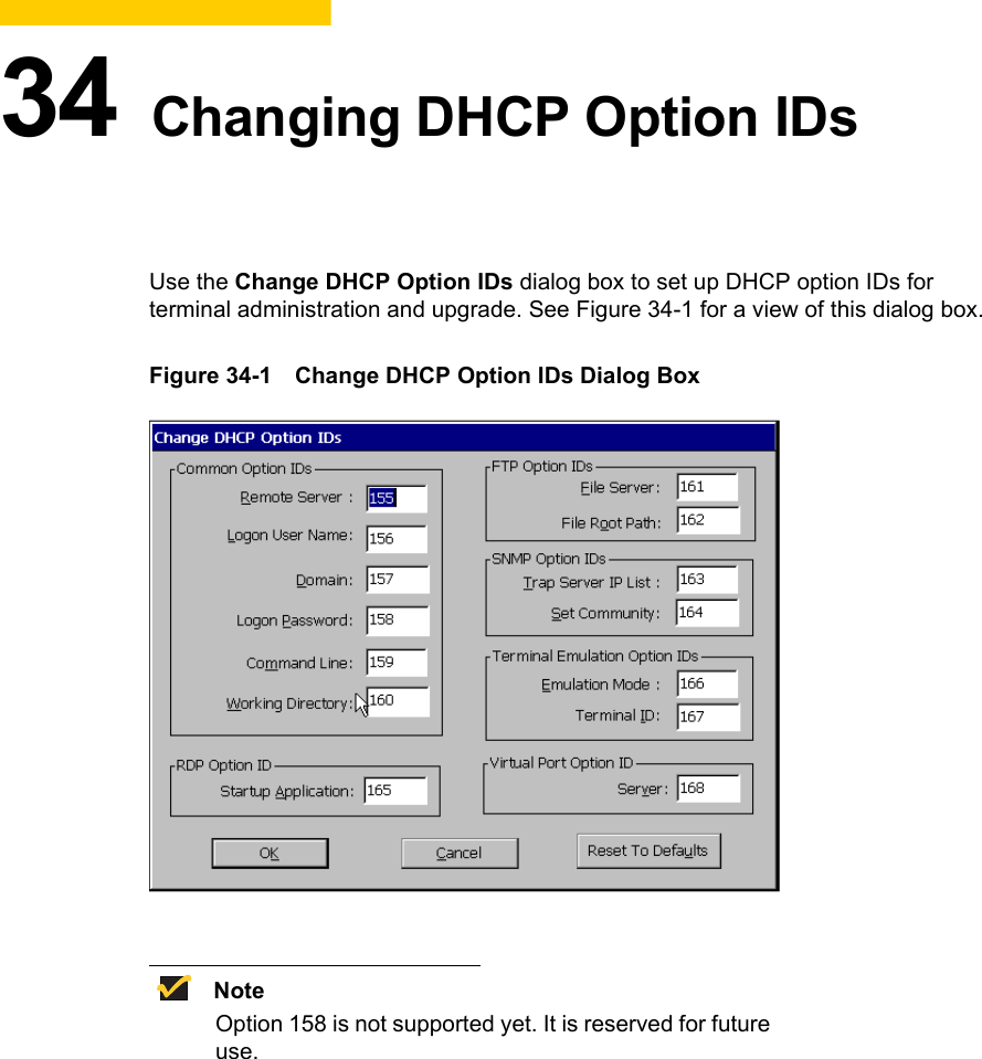
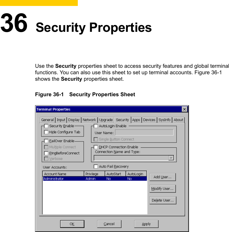
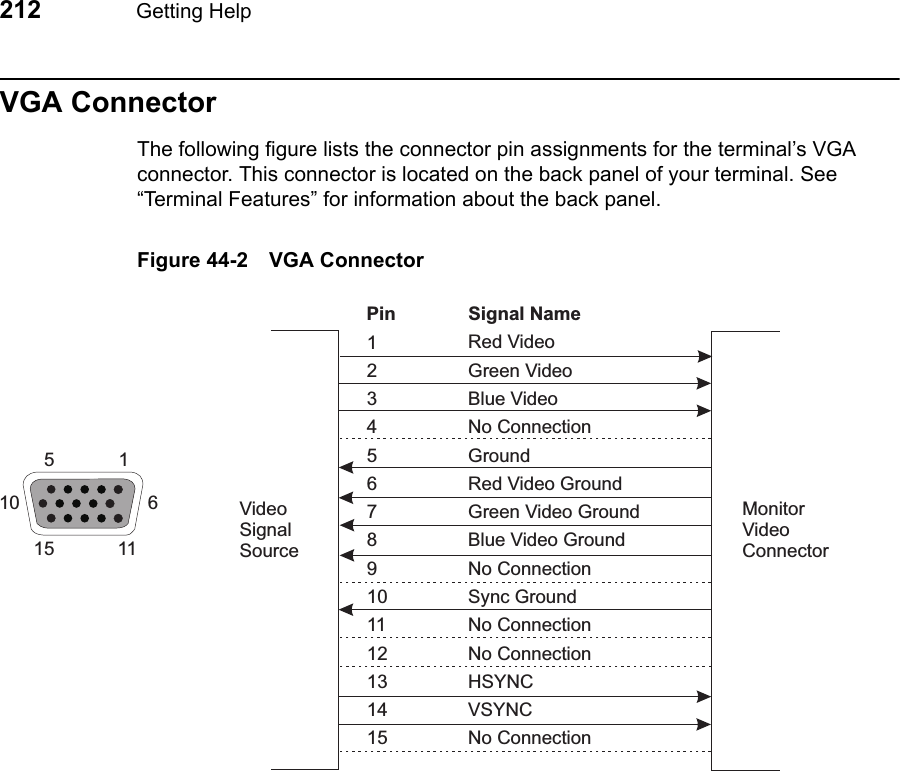
![49Instructions for using the terminal’s front panel are listed in the following table.Figure 8-3 3515SE/3715SE OSD (On-Screen Display) MenuTable 8-2 3515SE/3715SE/3720SE Terminal Front PanelButton FunctionMENU (OSD) To use:1. Press the MENU button to invoke the OSD (refer to the following figure).2. Press the plus [+] or minus [-] SELECT buttons to select the adjustment you want to make (see the following table, OSD Alignment, for settings).3. Press the ADJUST plus [+] or minus [-] buttons to make your adjustment.4. Press MENU to save your adjustments and close the OSD.NoteThe OSD can be invoked at any time the terminal is on, even while running an application. It automatically closes after a period of inactivity (2 minutes). If this happens before you complete your adjustments, press the MENU button to invoke the OSD again.SELECT (Brightness) Press the plus [+] and minus [-] buttons on the terminal’s front panel to increase or decrease the display’s brightness.ADJUST (Contrast) Press the plus [+] and minus [-] buttons on the terminal’s front panel to increase or decrease the display’s contrast. H-CENTERH-SIZEV-CENTERV-SIZEPIN +TRAPEZOIDROTATERECALL MODE+](https://usermanual.wiki/Wyse-Technology/WT3720/User-Guide-69302-Page-73.png)