X Micro Technology XWL-11GRIX 802.11 b/g WLAN Broadband Router User Manual
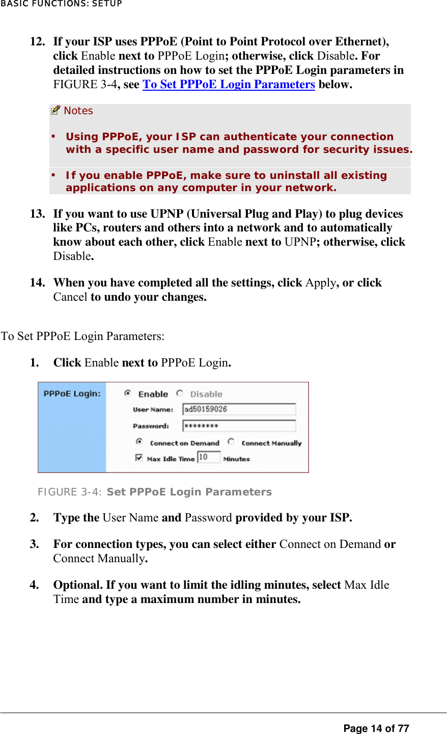
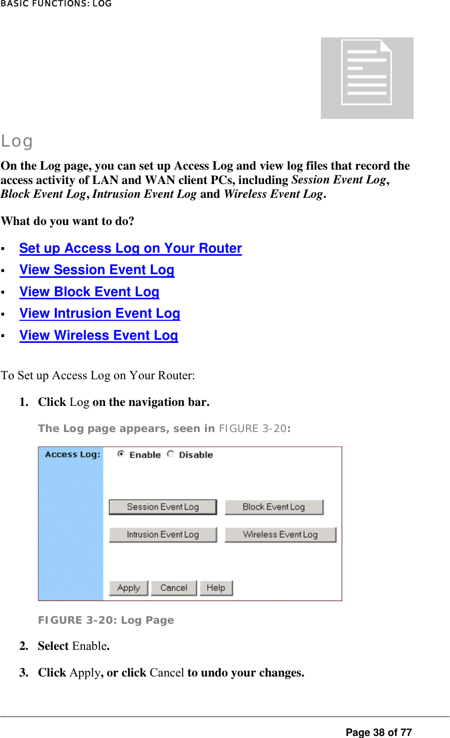
X-Micro Technology Corp., 802.11 b/g WLAN Broadband Router
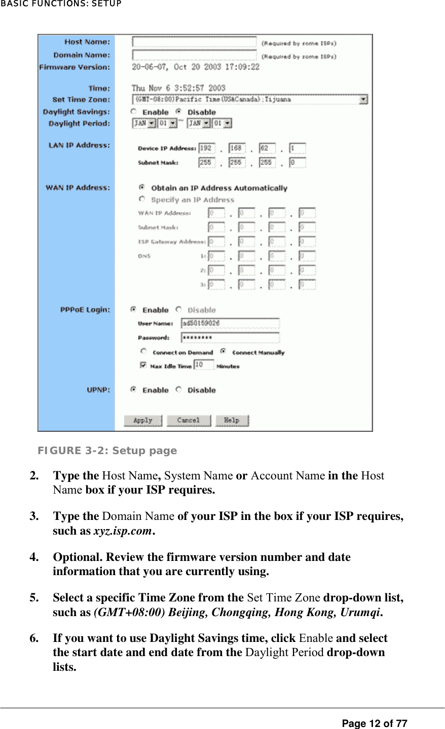
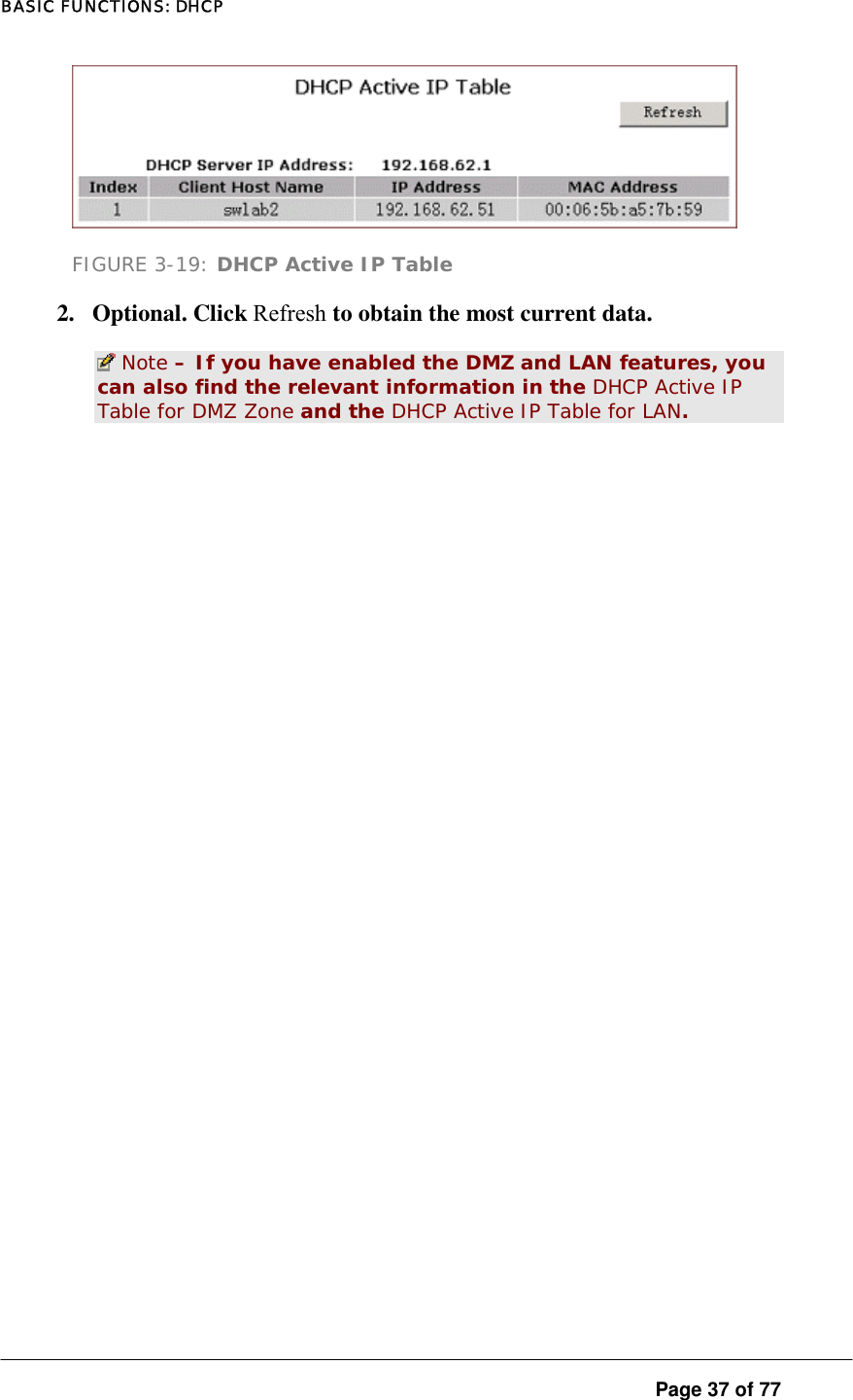
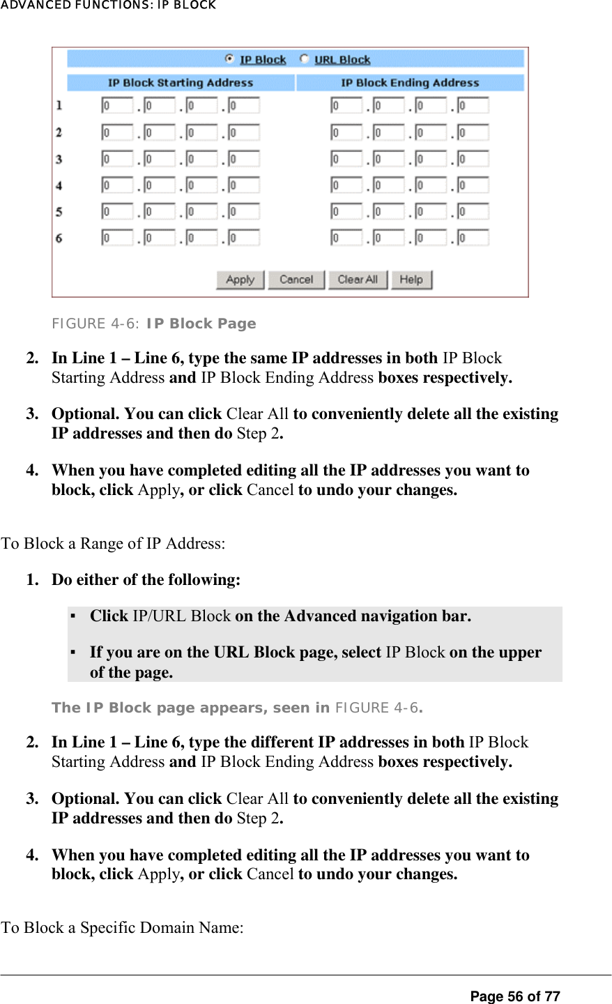
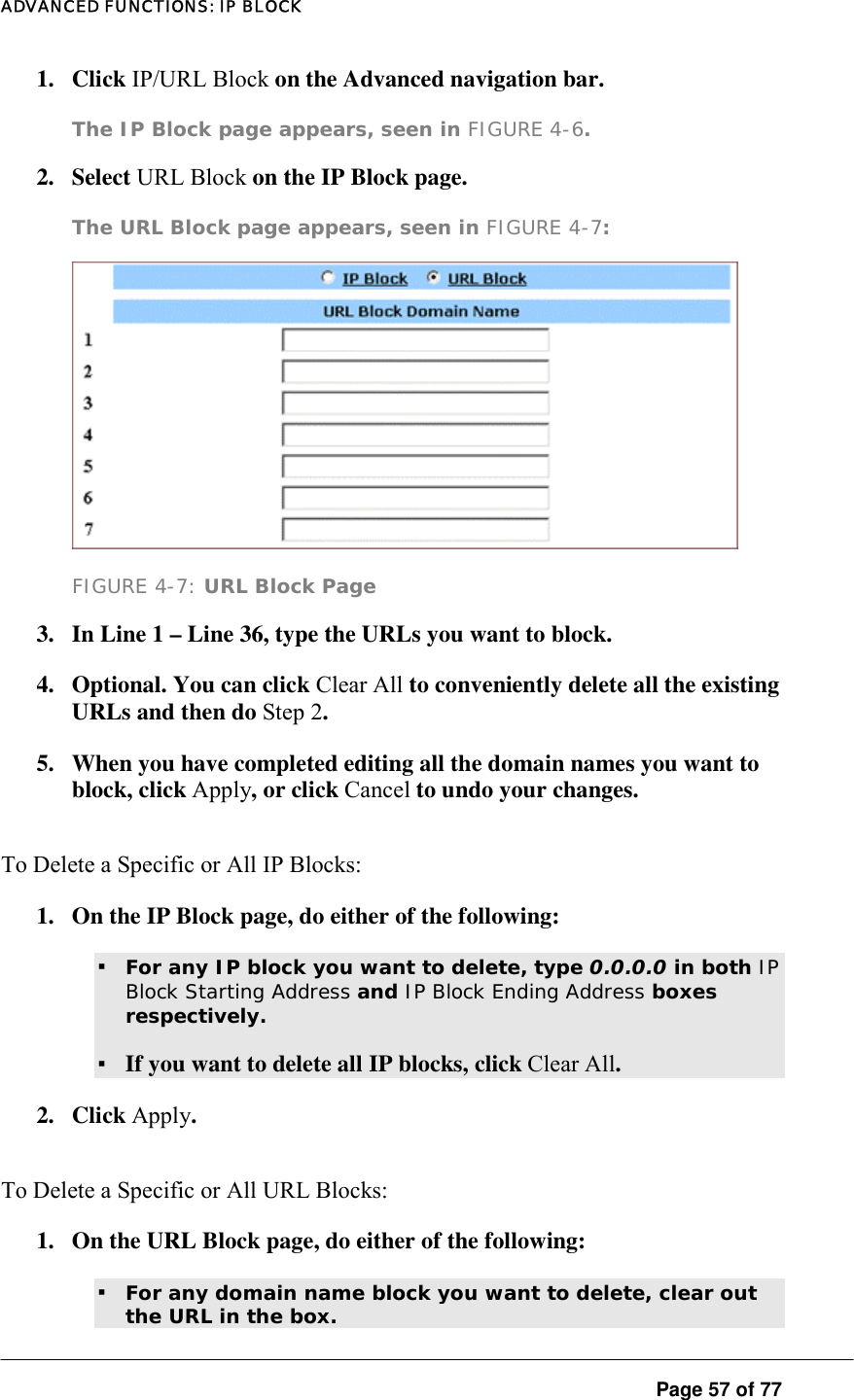
UserManual.wiki
>
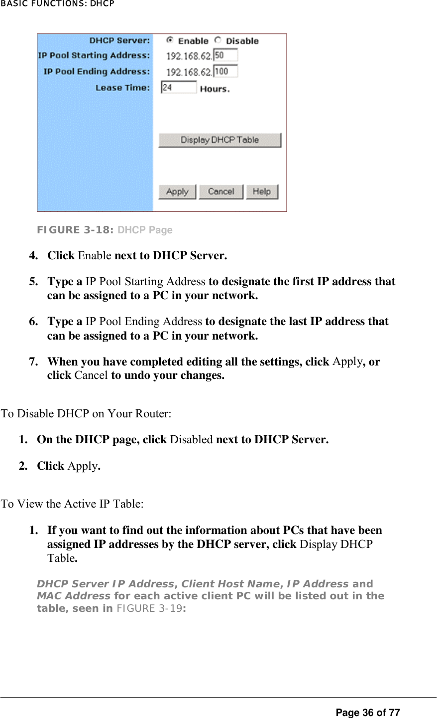
X Micro Technology
>
XWL 11GRIX User Manual
User Manual
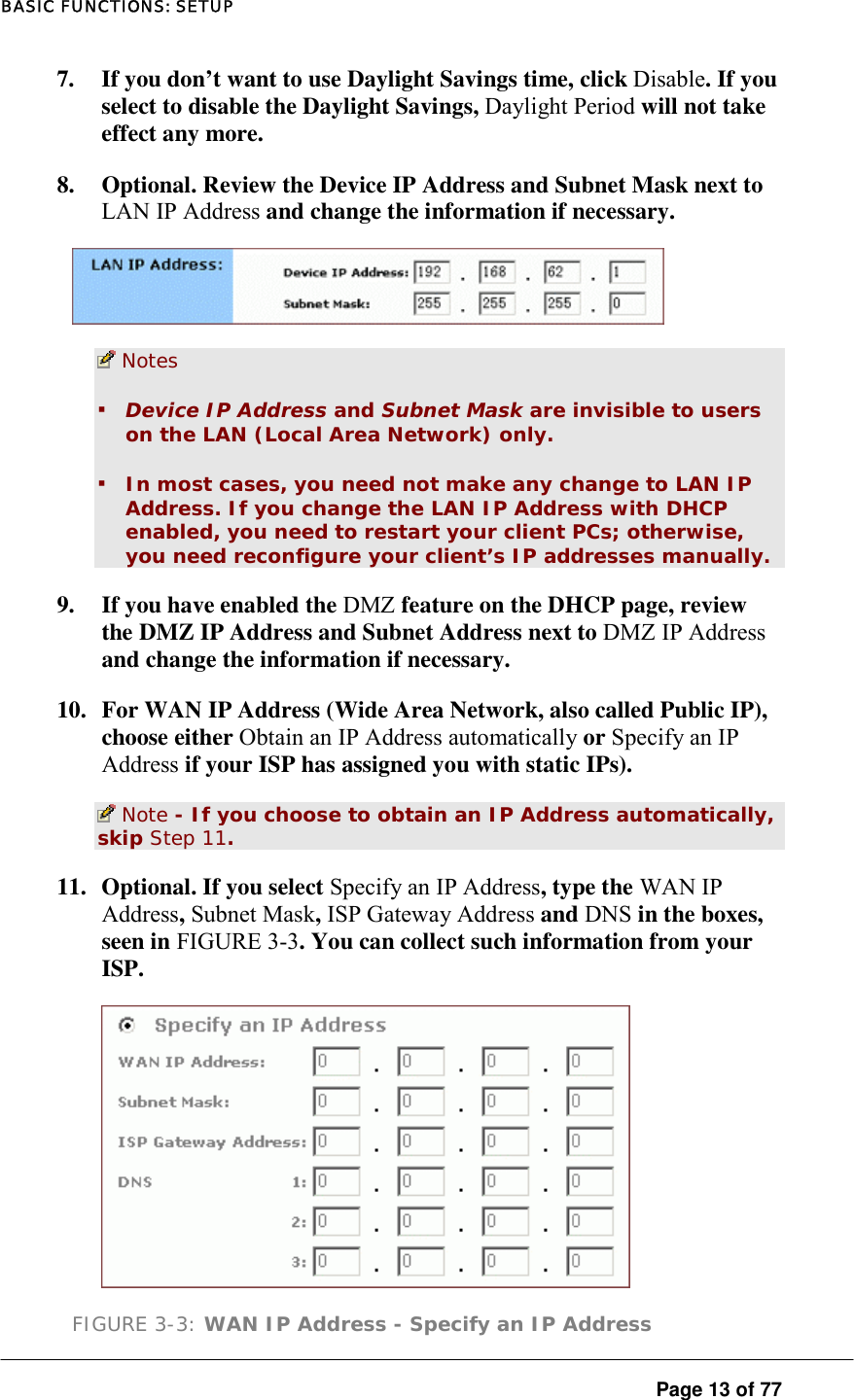
Navigation menu
Upload a User Manual
Namespaces
Wiki Guide
HTML
PDF
Info
Views
User Manual
Discussion / Help
Navigation
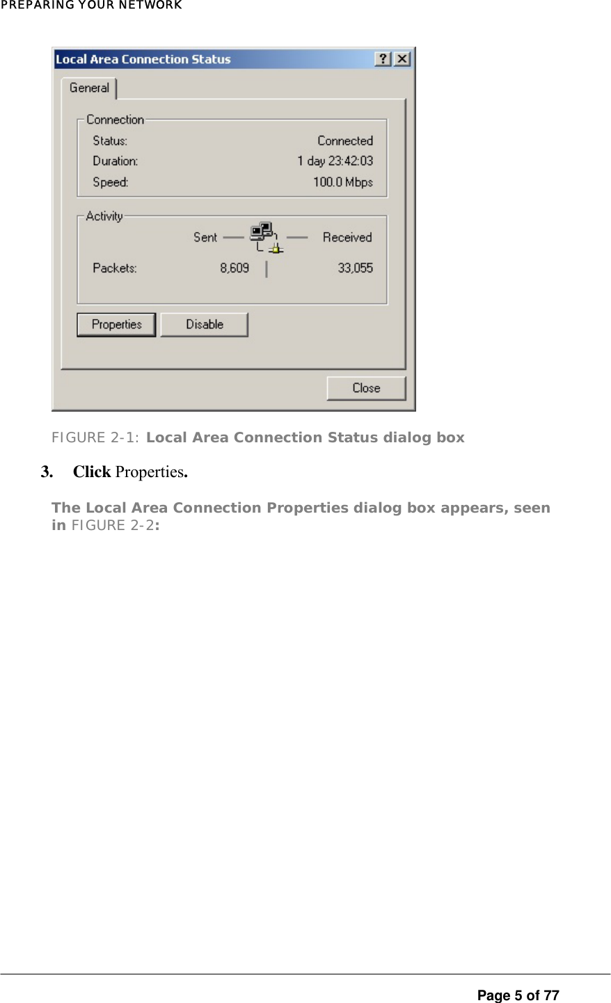
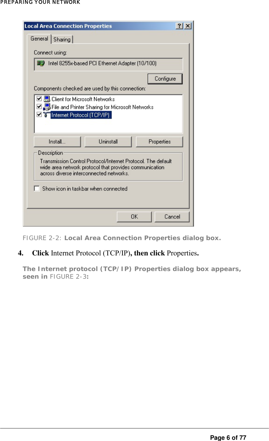
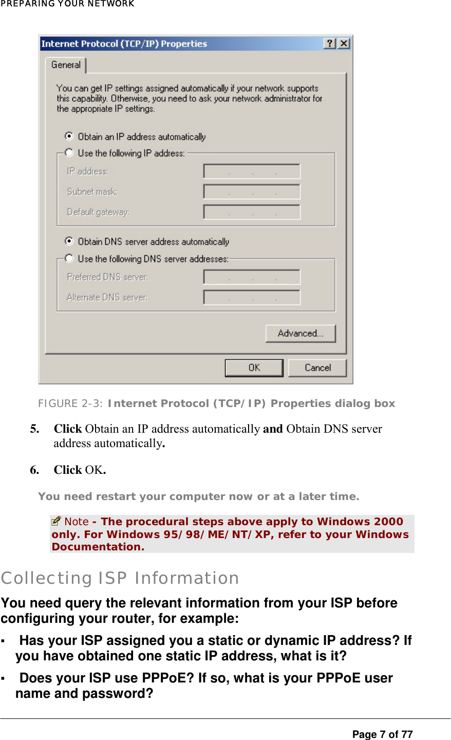
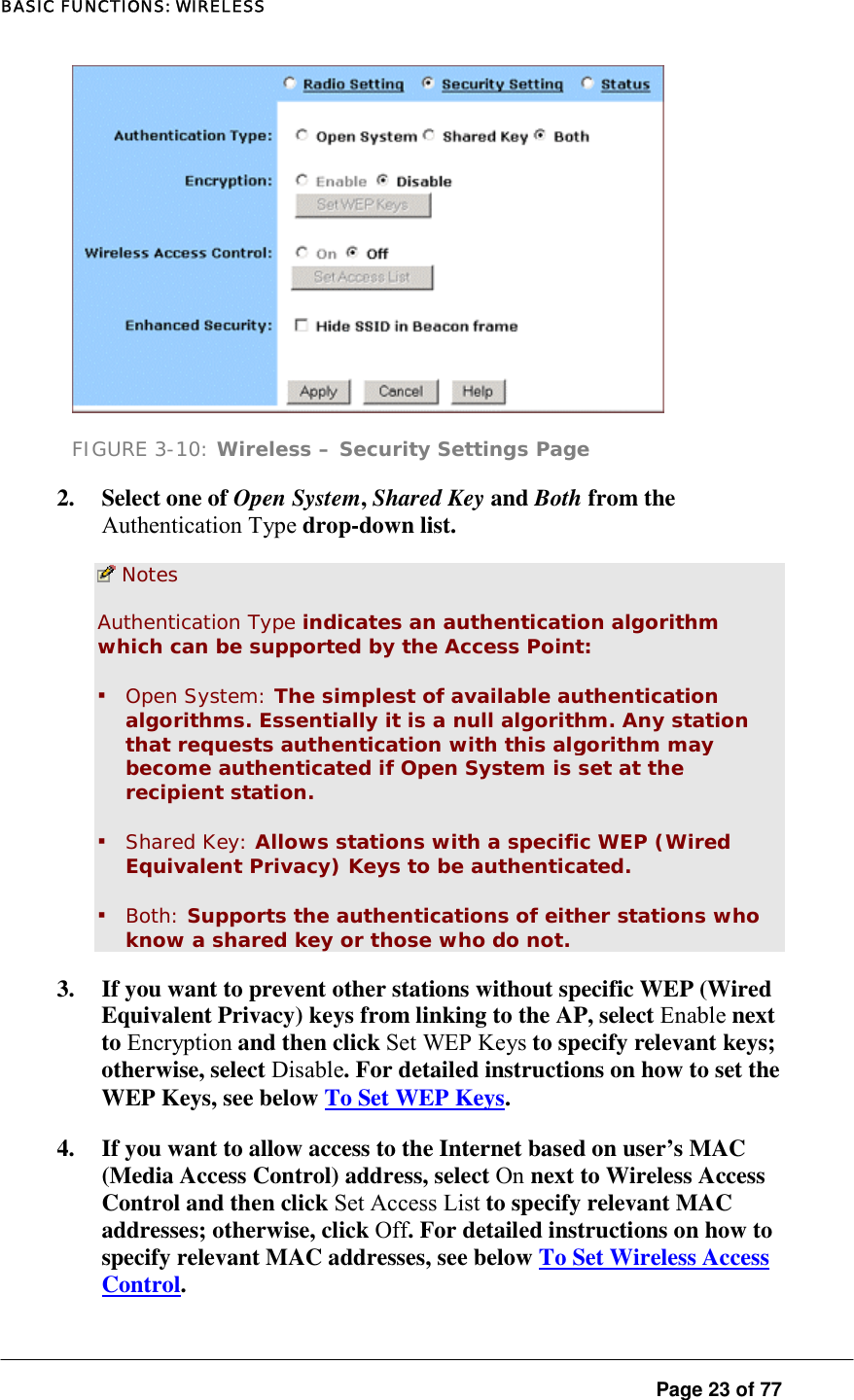
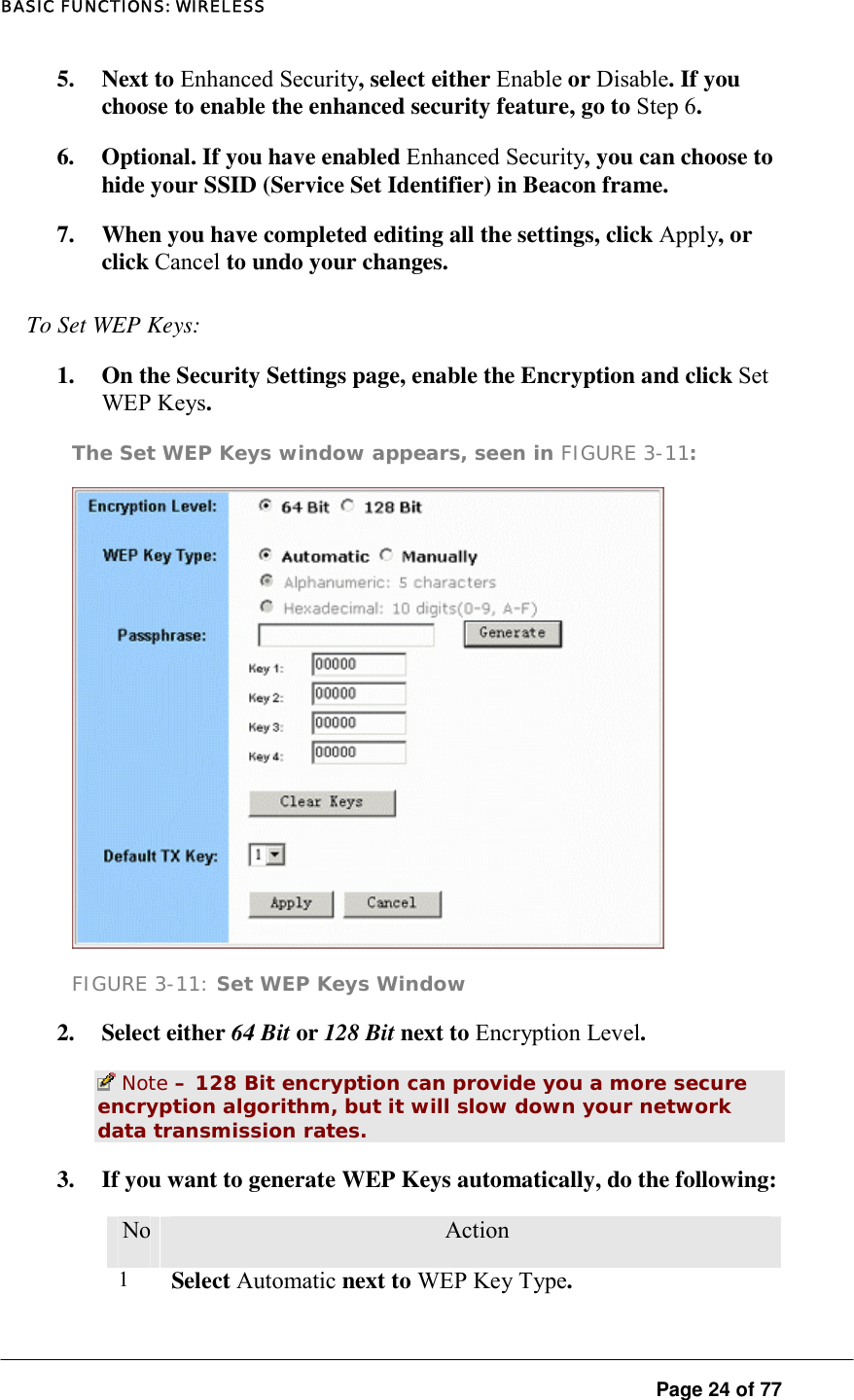
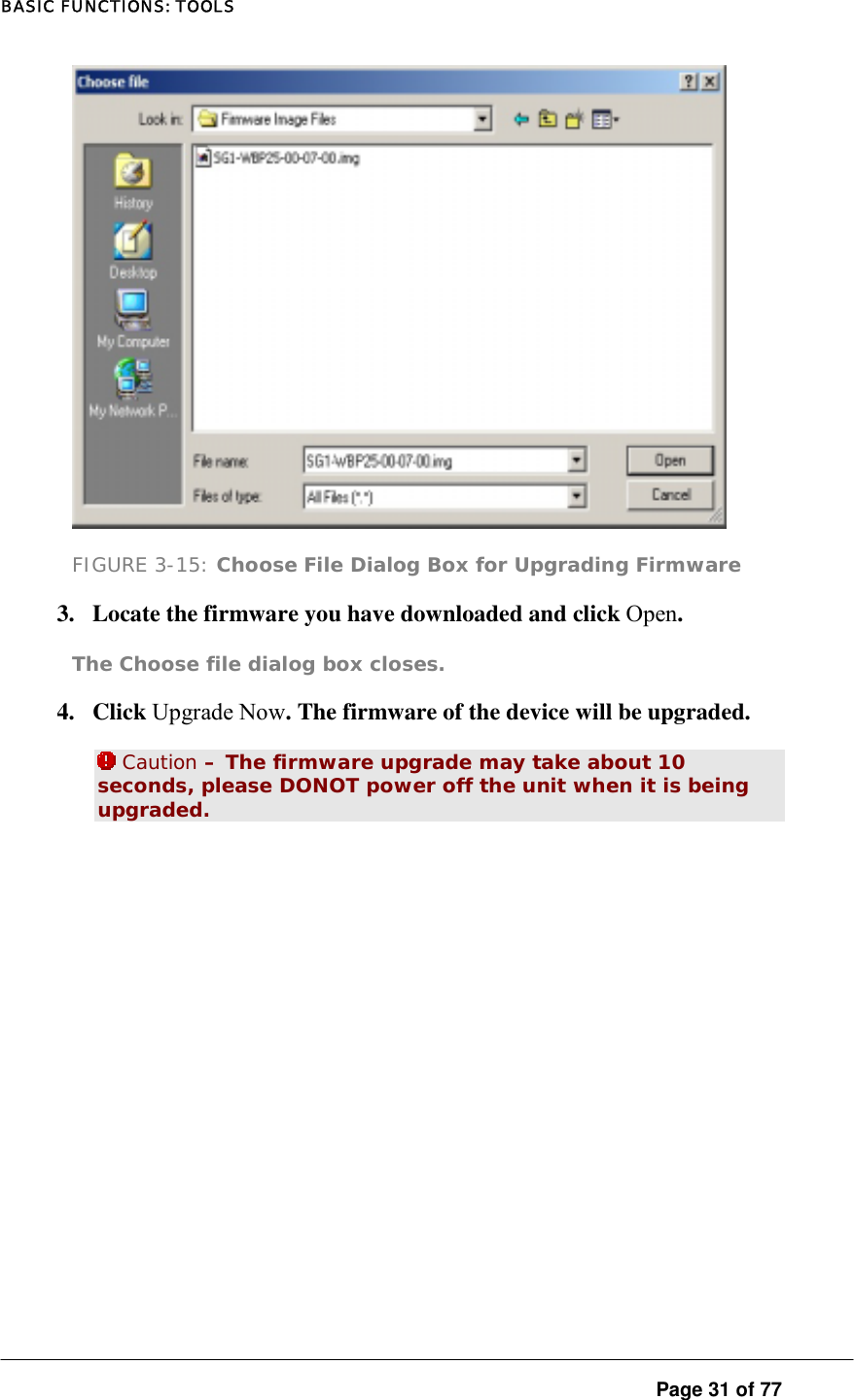
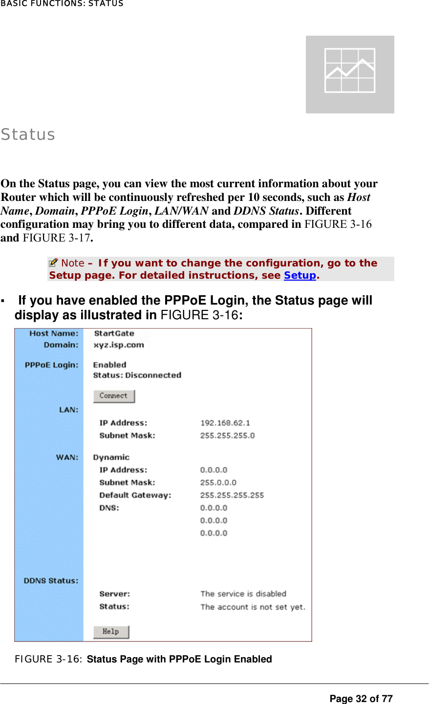
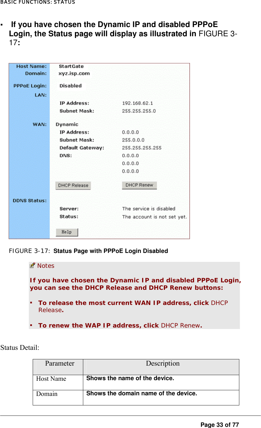
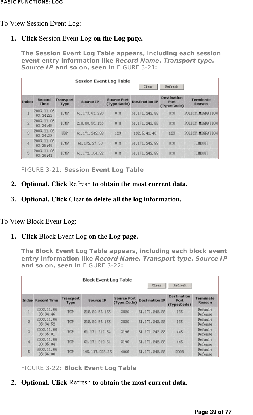
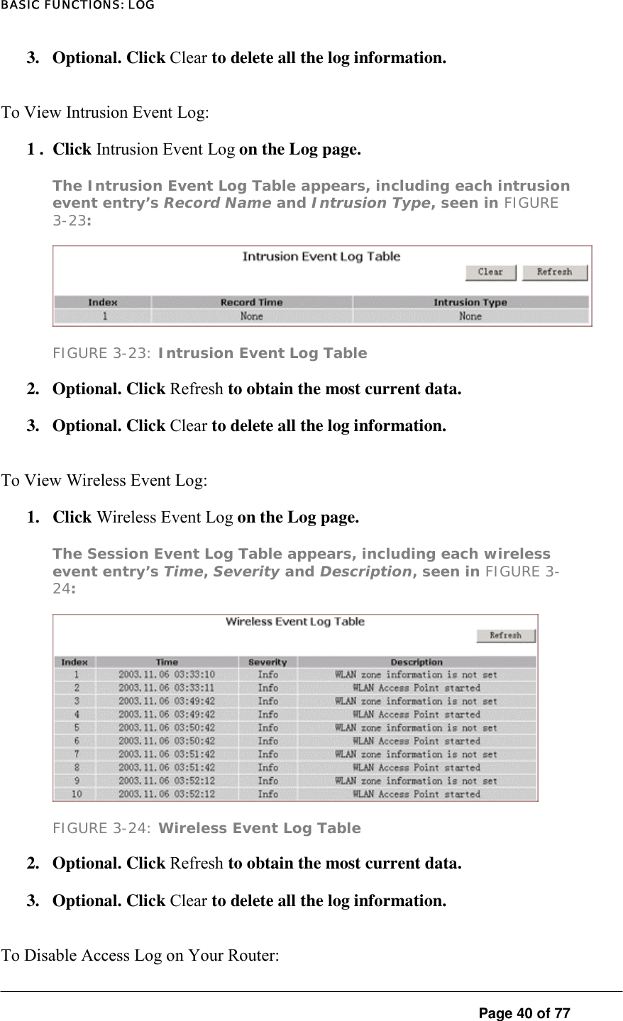
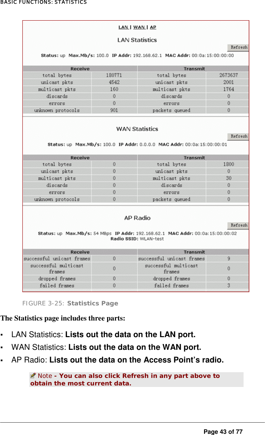
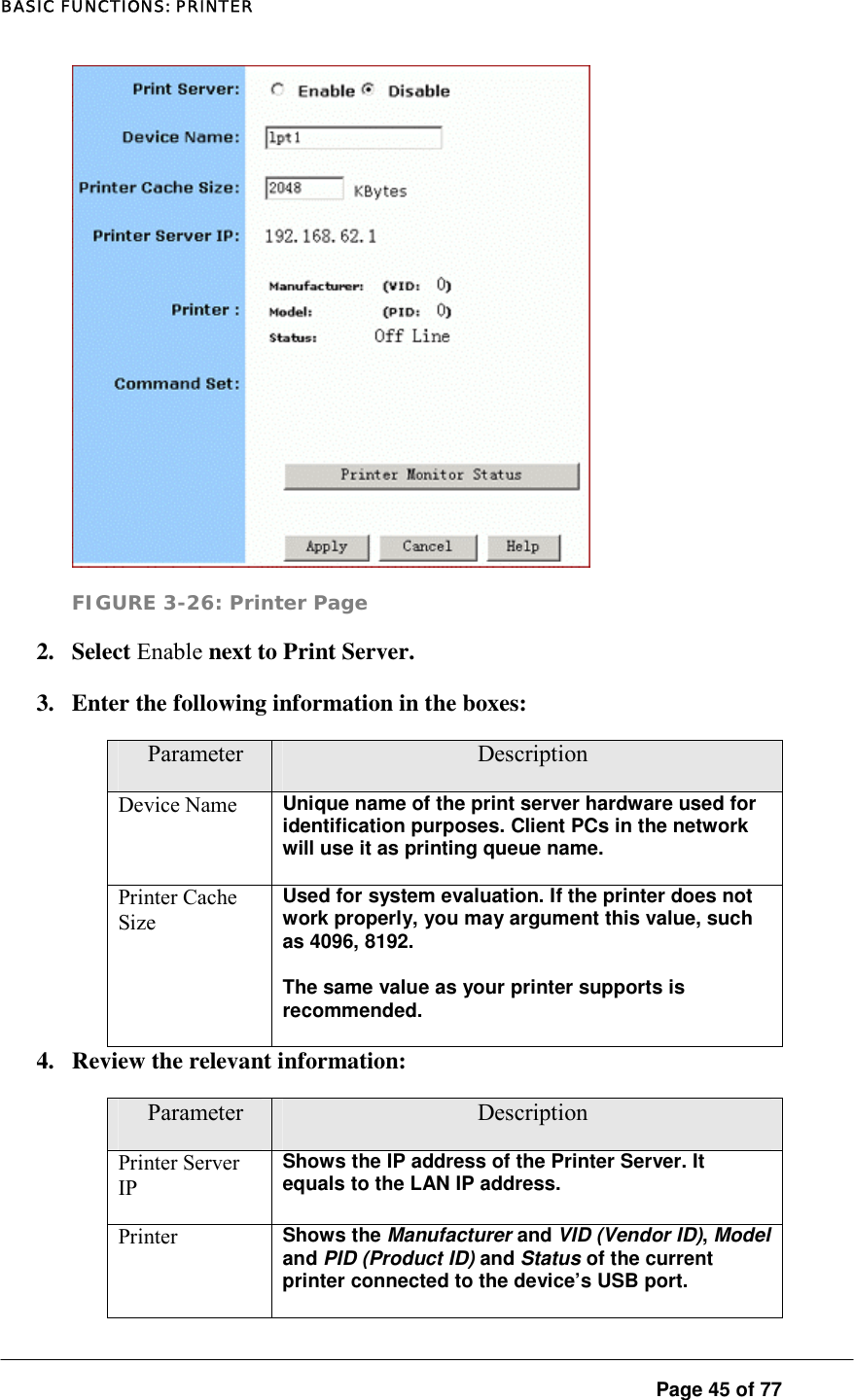
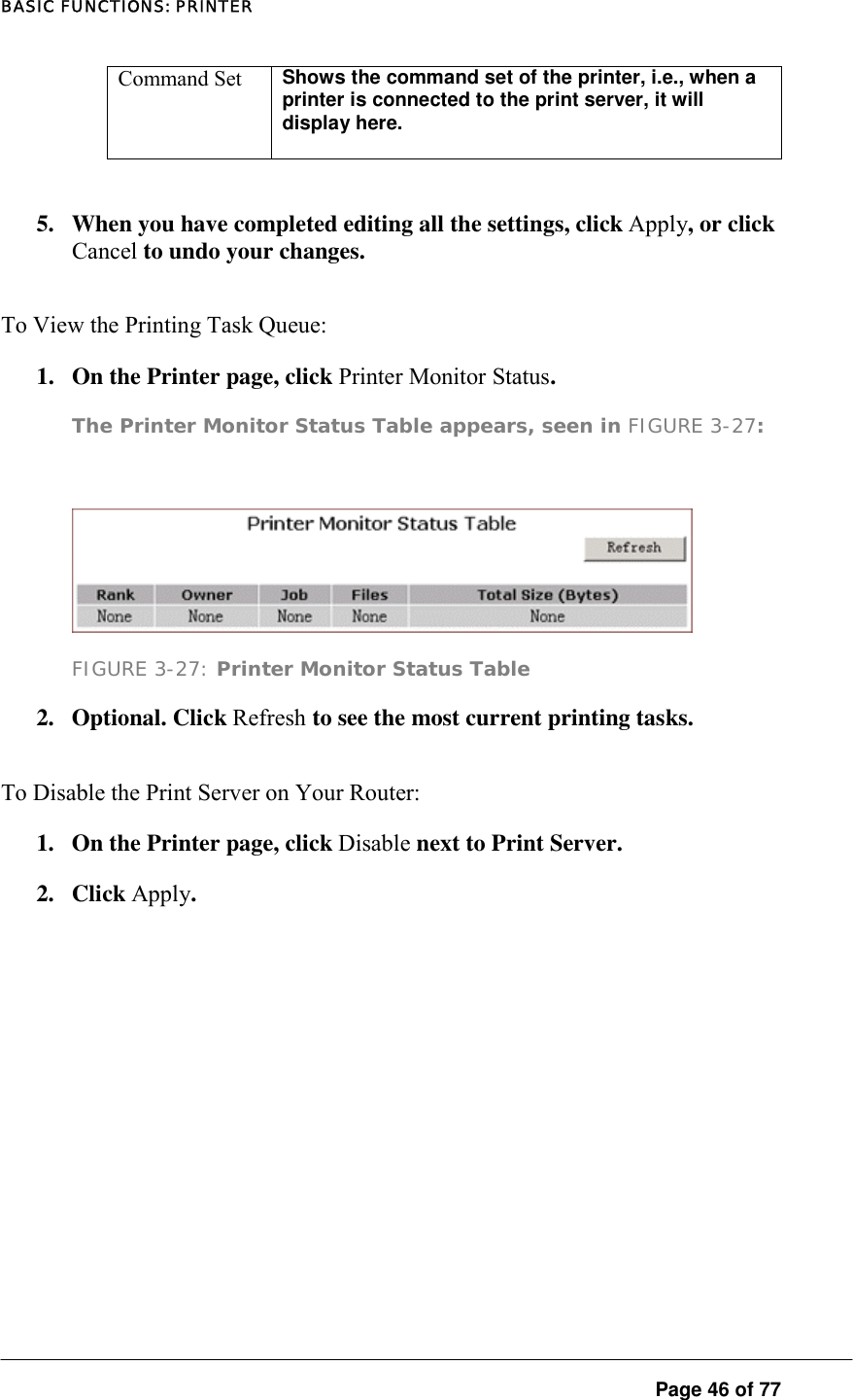
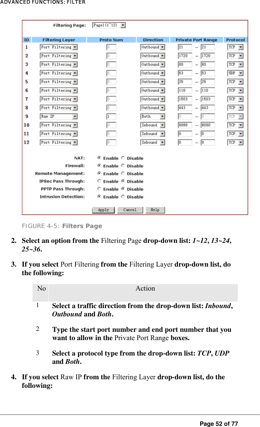
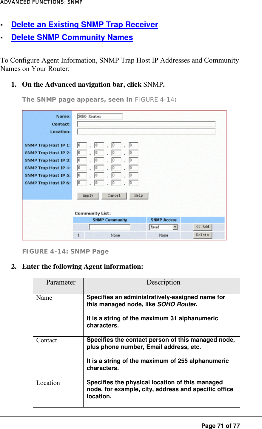
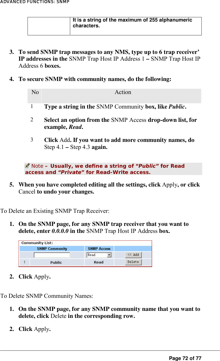
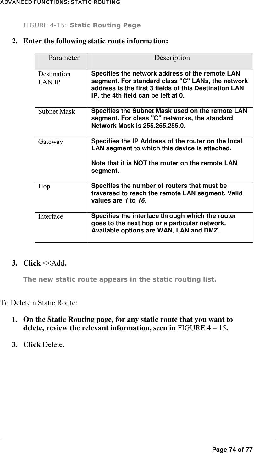
![BASIC FUNCTIONS Page 10 of 77 ] FIGURE 3-1: Logon dialog box 3. Type admin in the User Name box. 4. Type the password in the box. Note - The default password is 1234. You can change the password on the Tools page. For detailed instructions, see To Change the Administrative Password for Your Router. 5. Optional. To log on to the Administration Tool once for all, select the check box of Save this password in your password list. 6. Click OK. The Company AP Router Administration Tool appears. Note - The Administration Tool will time out after a period of idling, the Router may ask you to log on again.](https://usermanual.wiki/X-Micro-Technology/XWL-11GRIX/User-Guide-446319-Page-10.png)