X Micro Technology XWL-11GRIX 802.11 b/g WLAN Broadband Router User Manual
X-Micro Technology Corp., 802.11 b/g WLAN Broadband Router
User Manual

User’s Guide
WLAN 11g Broadband Router
Model: XWL-11GRIX
– IEEE 802.11g
Table of Contents
INSTALLING YOUR ROUTER-------3
System Requirement ----------------- 3
Installation Instructions------------- 3
PREPARING YOUR NETWORK -----4
Configuring Windows for IP
Networking---------------------------- 4
Collecting ISP Information ---------- 7
BASIC FUNCTIONS ---------------9
Setup----------------------------------11
Global Address-----------------------15
Wireless ------------------------------19
Tools ----------------------------------28
Status---------------------------------32
DHCP----------------------------------35
Log ------------------------------------38
Statistics------------------------------42
Printer --------------------------------44
ADVANCED FUNCTION---------- 47
Virtual Servers ---------------------- 48
Filters--------------------------------- 51
IP/URL Block ------------------------ 55
Special Apps ------------------------- 59
DMZ Host----------------------------- 63
MAC Clone---------------------------- 65
Dynamic DNS ------------------------ 66
Proxy DNS --------------------------- 68
SNMP --------------------------------- 70
Static Routing ----------------------- 73

INSTALLING YOUR ROUTER
Page 3 of 77
Installing Your Router
In this chapter, you’ll learn how to connect your router.
System Requirement
▪ Broadband Internet access
▪ Ethernet cables
▪ Wireless interface, if you want to use wireless functions
▪ Desktop or Laptop PCs with Ethernet interface
Installation Instructions
To Connect the Router:
1. Make sure all equipments are turned off, including the router,
Desktop or Laptop PCs, the cable and DSL modem, and so on.
2. Connect the WAN Port of the router to the cable and DSL modem,
Ethernet Server or the hub.
3. Connect your client PCs to the LAN Ports.
4. Connect the Power Adaptor (5VDC) to the power jack of the router
and plug the power cable into the outlet.
5. Turn on our PCs.
Chapter
1

PREPARING YOUR NETWORK
Page 4 of 77
B
Preparing Your Network
In this chapter, you’ll learn what to do before configuring your
network.
efore configuring your router, you need set up the computers in your
network for TCP/IP networking and collect relevant ISP information
if necessary.
Configuring Windows for IP Networking
Each computer in your network should be configured for
TCP/IP networking. There are two ways to configure your
computers:
▪ You are commended to use DHCP, then you can simply
choose to receive an IP address automatically. For detailed
instructions, see Configure Windows to Receive Dynamic IP
Address.
▪ If you don’t use DHCP, you need assign an IP address to
each computer manually. For detailed instructions, refer to
your Windows Documentation.
To Configure Windows to Receive Dynamic IP Address:
1. Click Start, then choose Settings > Network and Dial-up Connections.
2. Select the name of your ISP connection.
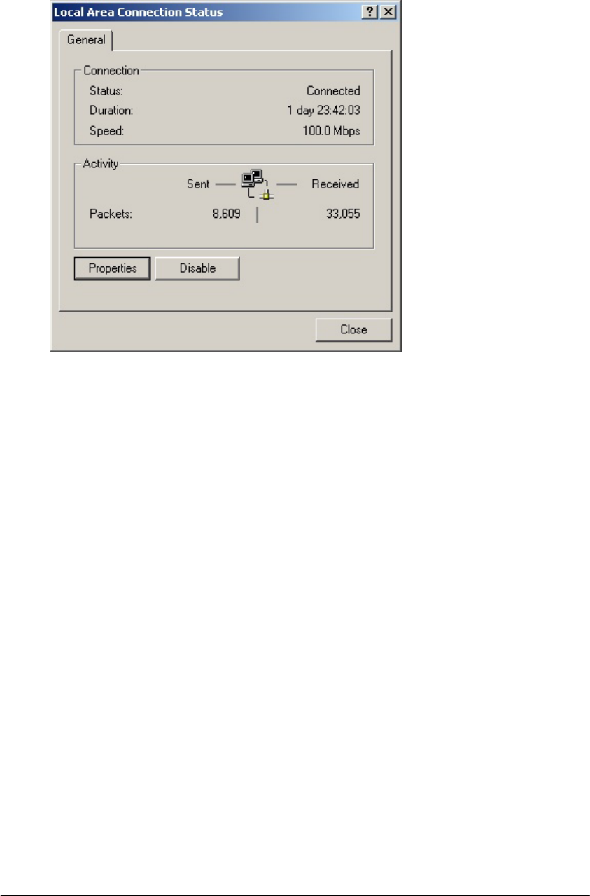
The Local Area Connection Status dialog box appears, seen in
FIGURE 2-1:
Chapter
2
PREPARING YOUR NETWORK
Page 5 of 77
FIGURE 2-1: Local Area Connection Status dialog box
3. Click Properties.
The Local Area Connection Properties dialog box appears, seen
in FIGURE 2-2:
PREPARING YOUR NETWORK
Page 6 of 77
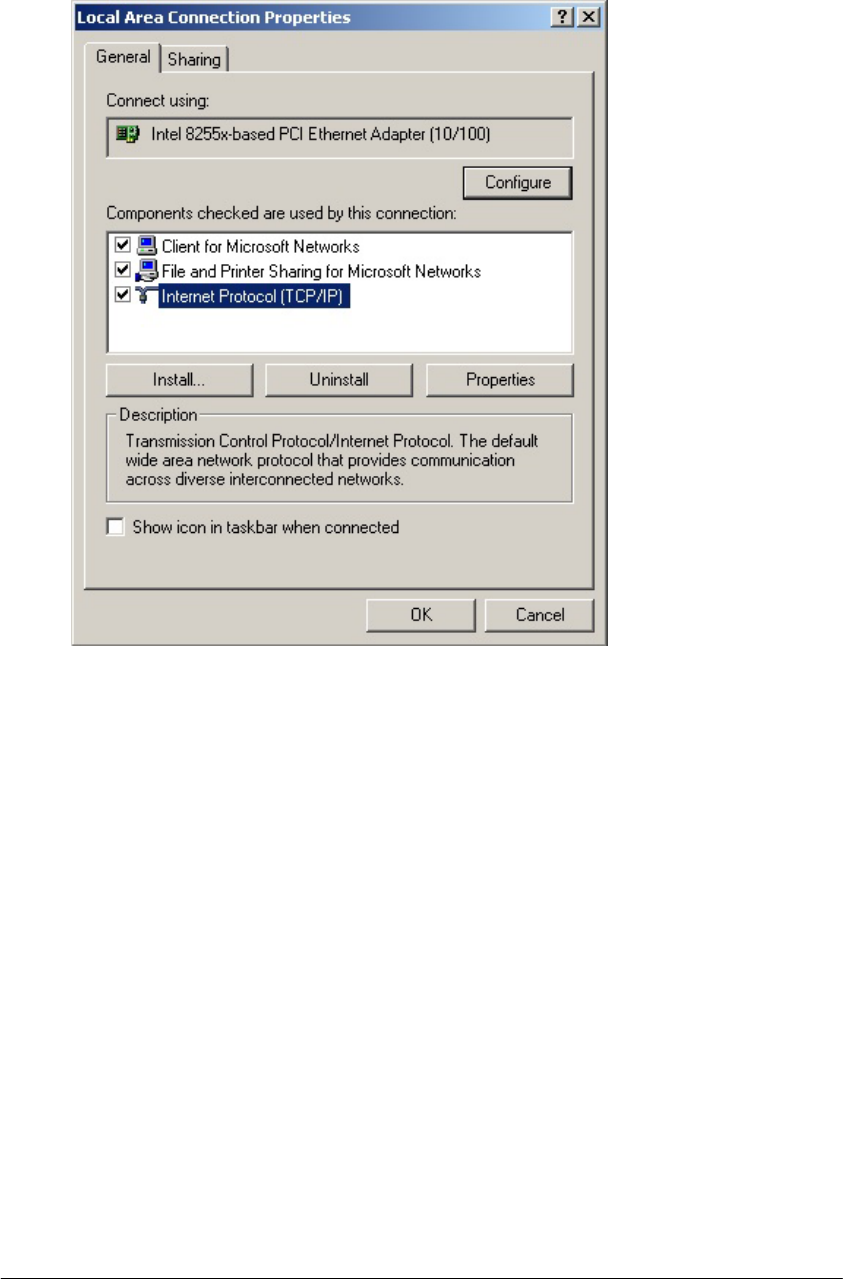
FIGURE 2-2: Local Area Connection Properties dialog box.
4. Click Internet Protocol (TCP/IP), then click Properties.
The Internet protocol (TCP/IP) Properties dialog box appears,
seen in FIGURE 2-3:
PREPARING YOUR NETWORK
Page 7 of 77
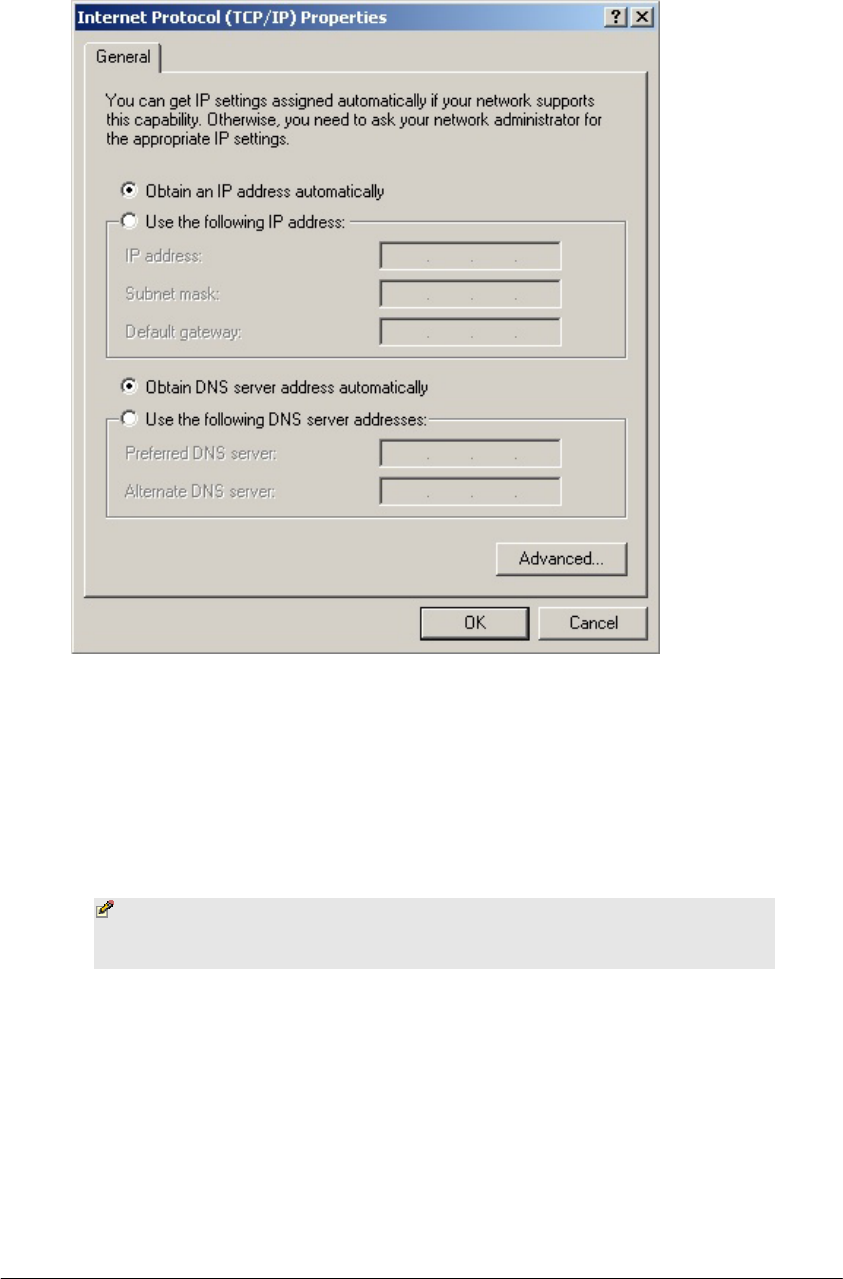
FIGURE 2-3: Internet Protocol (TCP/IP) Properties dialog box
5. Click
Obtain an IP address automatically and Obtain DNS server
address automatically.
6. Click OK.
You need restart your computer now or at a later time.
Note - The procedural steps above apply to Windows 2000
only. For Windows 95/98/ME/NT/XP, refer to your Windows
Documentation.
Collecting ISP Information
You need query the relevant information from your ISP before
configuring your router, for example:
▪ Has your ISP assigned you a static or dynamic IP address? If
you have obtained one static IP address, what is it?
▪ Does your ISP use PPPoE? If so, what is your PPPoE user
name and password?

PREPARING YOUR NETWORK
Page 8 of 77
If you are not sure of the above questions, call your ISP to clarify them.

BASIC FUNCTIONS
Page 9 of 77
T
Basic Functions
In this chapter, you will learn how to use basic functions that the
Company AP Router provides, including Setup, Global Address,
Wireless Tools, Status, DHCP, Log and Printer.
he Company AP Router provides you a Web-based Administration
Tool with which you can easily set up the router and customize the
basic router settings. You can use this Web-based Tool from any
computer in your network.
Notes
▪ Microsoft Internet Explorer 5.0 or later is highly
recommended for using this Web-based Tool.
▪ Graphics sampled in this chapter are provided for
illustrations only. They may slightly differ from your own
router screens.
To Open the Web-based Administration Tool:
1. Open the browser on your PC.
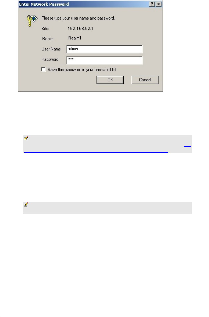
2. Type http://192.168.62.1 in the Address bar.
The Logon dialog box appears, seen in FIGURE 3-1:
Chapter
3
BASIC FUNCTIONS
Page 10 of 77
]
FIGURE 3-1: Logon dialog box
3. Type admin in the User Name box.
4. Type the password in the box.
Note - The default password is 1234. You can change the
password on the Tools page. For detailed instructions, see To
Change the Administrative Password for Your Router.
5. Optional. To log on to the Administration Tool once for all, select
the check box of Save this password in your password list.
6. Click OK.
The Company AP Router Administration Tool appears.
Note - The Administration Tool will time out after a period
of idling, the Router may ask you to log on again.

BASIC FUNCTIONS: SETUP
Page 11 of 77
Setup
The Setup page allows you to edit the basic configuration parameters for
your router, such as Host Name, Domain Name, LAN IP Address, WAN IP
Address, PPPoE Login, UPNP, and so on.
In most cases, the default settings will be Okay for you. However, different
ISPs (Internet Service Provider) may ask for specific requirements, please
check it with your ISP if you are not sure.
To Configure Setup Parameters:
1. Click Setup on the navigation bar.
The Setup page appears, seen in FIGURE 3-2:
³
BASIC FUNCTIONS: SETUP
Page 12 of 77
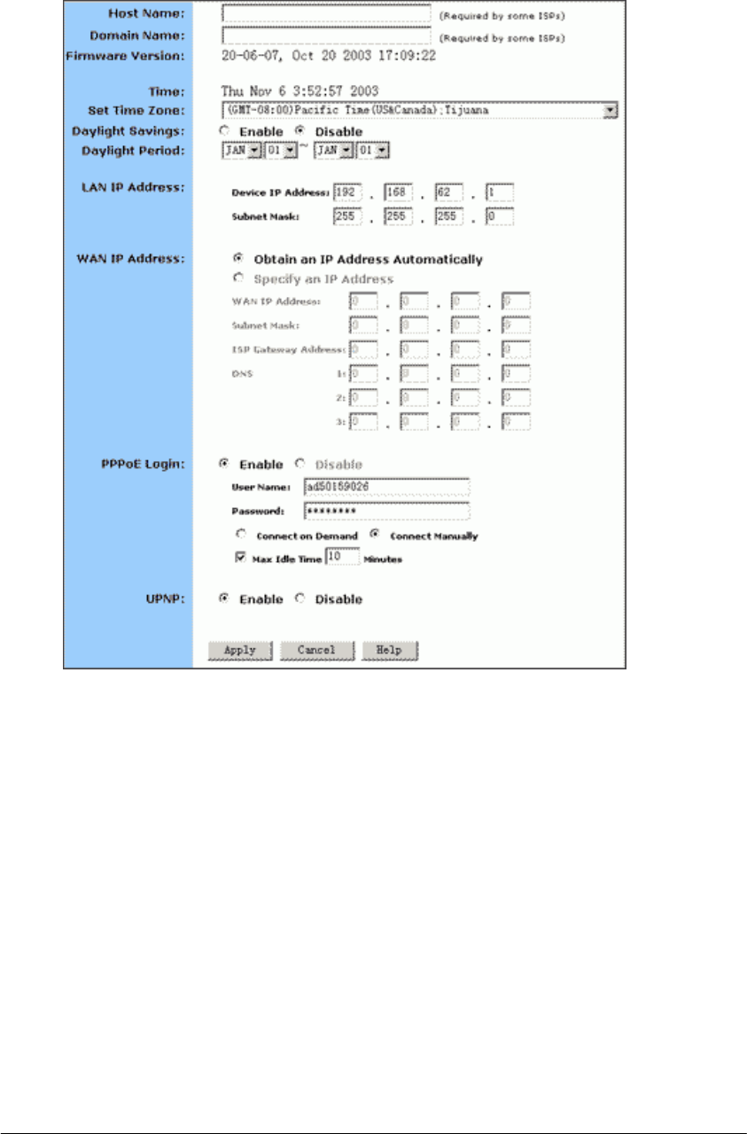
FIGURE 3-2: Setup page
2. Type the Host Name, System Name or Account Name in the Host
Name box if your ISP requires.
3. Type the Domain Name of your ISP in the box if your ISP requires,
such as xyz.isp.com.
4. Optional. Review the firmware version number and date
information that you are currently using.
5. Select a specific Time Zone from the Set Time Zone drop-down list,
such as (GMT+08:00) Beijing, Chongqing, Hong Kong, Urumqi.
6. If you want to use Daylight Savings time, click Enable and select
the start date and end date from the Daylight Period drop-down
lists.
BASIC FUNCTIONS: SETUP
Page 13 of 77
7. If you don’t want to use Daylight Savings time, click Disable. If you
select to disable the Daylight Savings, Daylight Period will not take
effect any more.
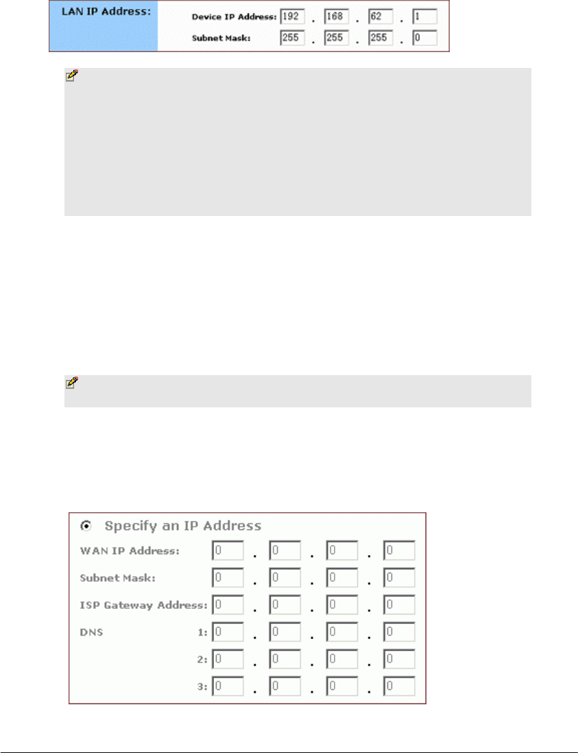
8. Optional. Review the Device IP Address and Subnet Mask next to
LAN IP Address and change the information if necessary.
Notes
▪ Device IP Address and Subnet Mask are invisible to users
on the LAN (Local Area Network) only.
▪ In most cases, you need not make any change to LAN IP
Address. If you change the LAN IP Address with DHCP
enabled, you need to restart your client PCs; otherwise,
you need reconfigure your client’s IP addresses manually.
9. If you have enabled the DMZ feature on the DHCP page, review
the DMZ IP Address and Subnet Address next to DMZ IP Address
and change the information if necessary.
10. For WAN IP Address (Wide Area Network, also called Public IP),
choose either Obtain an IP Address automatically or Specify an IP
Address if your ISP has assigned you with static IPs).
Note - If you choose to obtain an IP Address automatically,
skip Step 11.
11. Optional. If you select Specify an IP Address, type the WAN IP
Address, Subnet Mask, ISP Gateway Address and DNS in the boxes,
seen in FIGURE 3-3. You can collect such information from your
ISP.
FIGURE 3-3: WAN IP Address - Specify an IP Address
BASIC FUNCTIONS: SETUP
Page 14 of 77
12. If your ISP uses PPPoE (Point to Point Protocol over Ethernet),
click Enable next to PPPoE Login; otherwise, click Disable. For
detailed instructions on how to set the PPPoE Login parameters in
FIGURE 3-4, see To Set PPPoE Login Parameters below.
Notes
▪ Using PPPoE, your ISP can authenticate your connection
with a specific user name and password for security issues.
▪ If you enable PPPoE, make sure to uninstall all existing
applications on any computer in your network.
13. If you want to use UPNP (Universal Plug and Play) to plug devices
like PCs, routers and others into a network and to automatically
know about each other, click Enable next to UPNP; otherwise, click
Disable.
14. When you have completed all the settings, click Apply, or click
Cancel to undo your changes.
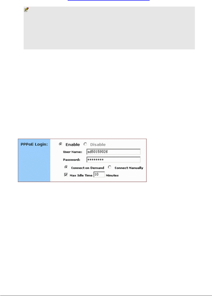
To Set PPPoE Login Parameters:
1. Click Enable next to PPPoE Login.
FIGURE 3-4: Set PPPoE Login Parameters
2. Type the User Name and Password provided by your ISP.
3. For connection types, you can select either Connect on Demand or
Connect Manually.
4. Optional. If you want to limit the idling minutes, select Max Idle
Time and type a maximum number in minutes.

BASIC FUNCTIONS: GLOBAL ADDRESS
Page 15 of 77
Global Address
On the Global Address page, you can set up NAT (Network Address
Translation) to provide internal-to-external IP address mappings.
Notes
▪ If you want to use Global Address mapping, you must
enable NAT on the Filters page. For detailed instructions,
see To Set up a Port Filtering or Raw IP Filter.
▪ If you have chosen to retrieve an IP address automatically,
you will not need to use this function. Instead, the default
public IP address will display on the Global Address page.
Have you enabled DMZ on the DHCP page? Depending on whether DMZ is
enabled, you may follow different procedural steps.
What do you want to do?
▪ Set up Global Address with DMZ Disabled
▪ Set up Global Address with DMZ Enabled
▪ Remove Global Addresses
To Set up Global Address with DMZ Disabled:
1. Click Global Address on the navigation bar.
The Global Address page with DMZ Disabled appears, seen in
FIGURE 3-5:
à
BASIC FUNCTIONS: GLOBAL ADDRESS
Page 16 of 77
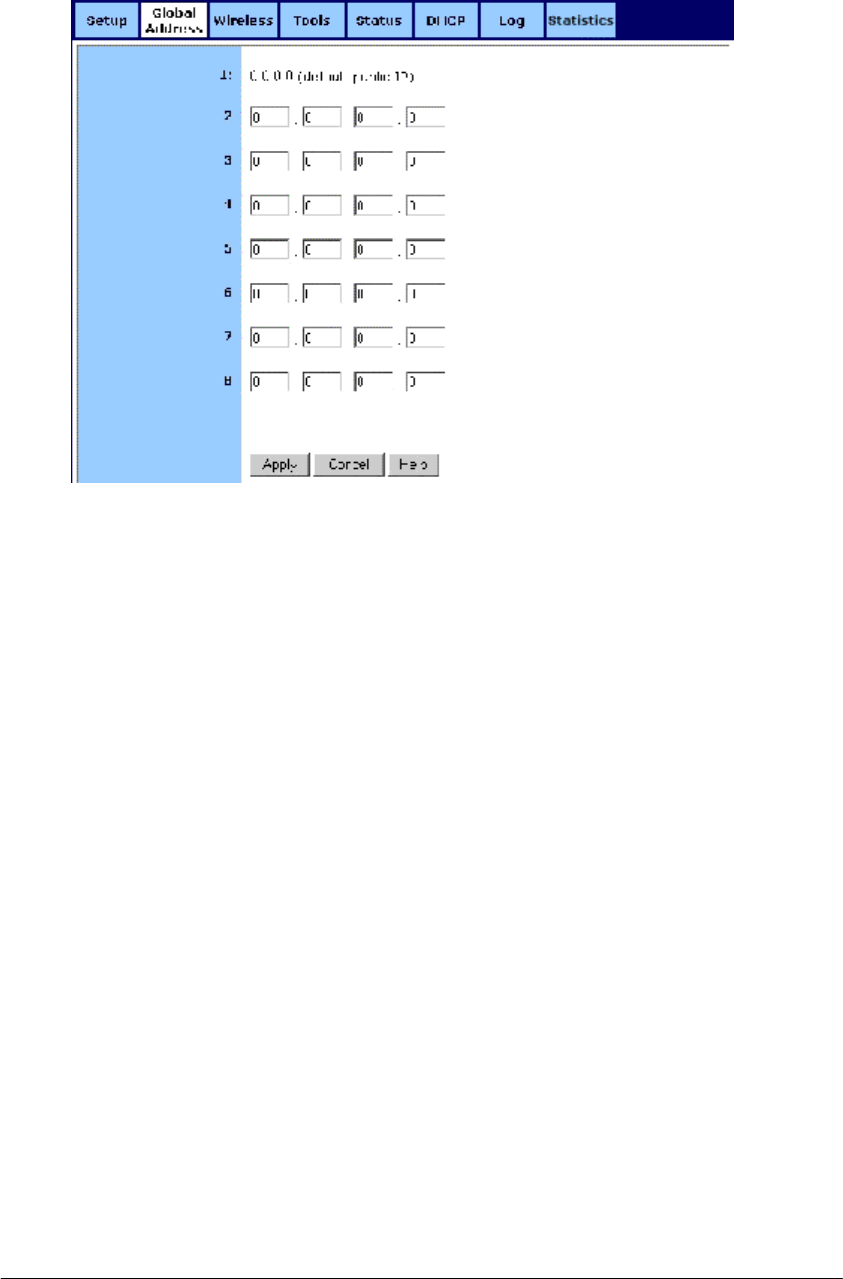
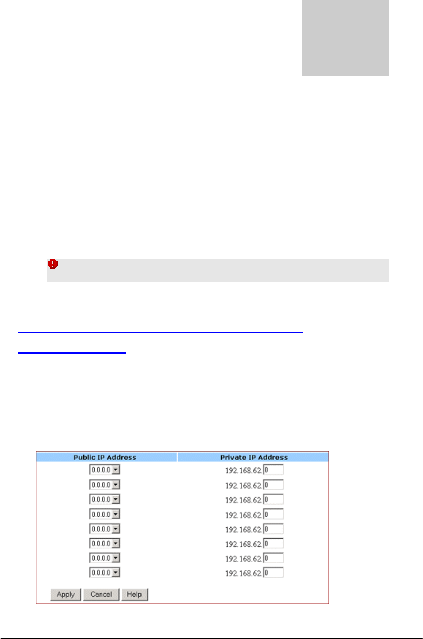
FIGURE 3-5: Global Address Page with DMZ Disabled
2. Review the first line in the above figure. It shows the default WAN
IP address which is specified on the Setup page. If your ISP assigns
you an IP address automatically, it will display here.
3. In Line 2 – Line 8, you can list up to 7 additional static, external IP
addresses provided by your ISP.
4. When you have completed editing all the settings, click Apply, or
click Cancel to undo your changes.
To Set up Global Address with DMZ Enabled:
1. Click Global Address on the navigation bar.
The Global Address page with DMZ Enabled appears, seen in
FIGURE 3-6:
BASIC FUNCTIONS: GLOBAL ADDRESS
Page 17 of 77
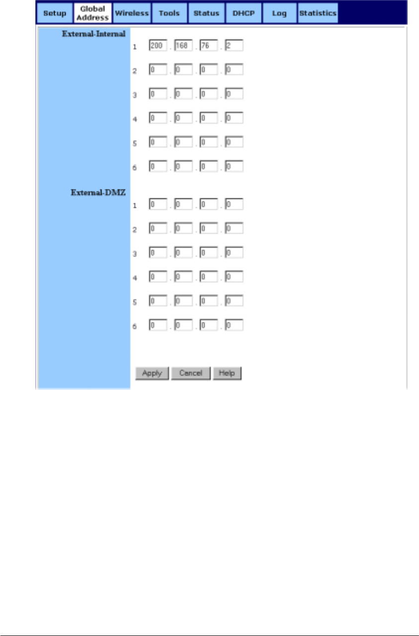
FIGURE 3-6: Global Address Page with DMZ Enabled
2. Review the first line in the above figure. It shows the default WAN
IP address which is specified on the Setup page. If your ISP assigns
you an IP address automatically, it will display here.
3. Next to External - Internal, you can list up to 6 static, external IP
addresses provided by your ISP.
4. Next to External – DMZ, define for your DMZ network up to 6
static, external global IP addresses provided by your ISP.
5. When you have completed editing all the settings, click Apply, or
click Cancel to undo your changes.
To Remove Global Addresses:

BASIC FUNCTIONS: GLOBAL ADDRESS
Page 18 of 77
1. Click Global Address on the navigation bar.
2. For any entry you want to delete, enter 0.0.0.0, and click Apply.

BASIC FUNCTIONS: WIRELESS
Page 19 of 77
Wireless
Using Wireless, you can configure your router for wireless access. There are
three parts on the Wireless page:
▪ Radio Settings: Allows you to configure your Gateway for
wireless access, including Wireless Enable/Disable, Mode,
ESSID, Beacon Interval, RTS Threshold, Preamble Type,
Distribution System, and so on.
▪ Security Setting: Allows you to configure your Gateway for
security issues.
▪ Status: Allows you to find out your Gateway’s AP Radio
statistics and wireless devices of which the AP (Access Point)
is aware.
You can easily toggle between the above three parts on the Wireless page.
On the Radio Settings page, Wireless Distribution System as defined by the
IEEE 802.11 standard has been made available on the Company AP Router
now. Hence, it is possible to wirelessly connect Access Points using up to 8
MAC Addresses of PC cards, so that you can extend a wired infrastructure
to locations where cabling is not available. Thus those users can roam or stay
connected to the available network resources.
What do you want to do?
▪ Set the Wireless Radio Parameters
▪ Set the Wireless Security Parameters
▪ Review Wireless Status
▪ Disable Wireless
To Set the Wireless Radio Parameters:
1. On the Wireless page, select Radio Settings.
The Radio Settings page appears, seen in FIGURE 3-7:
ª
BASIC FUNCTIONS: WIRELESS
Page 20 of 77
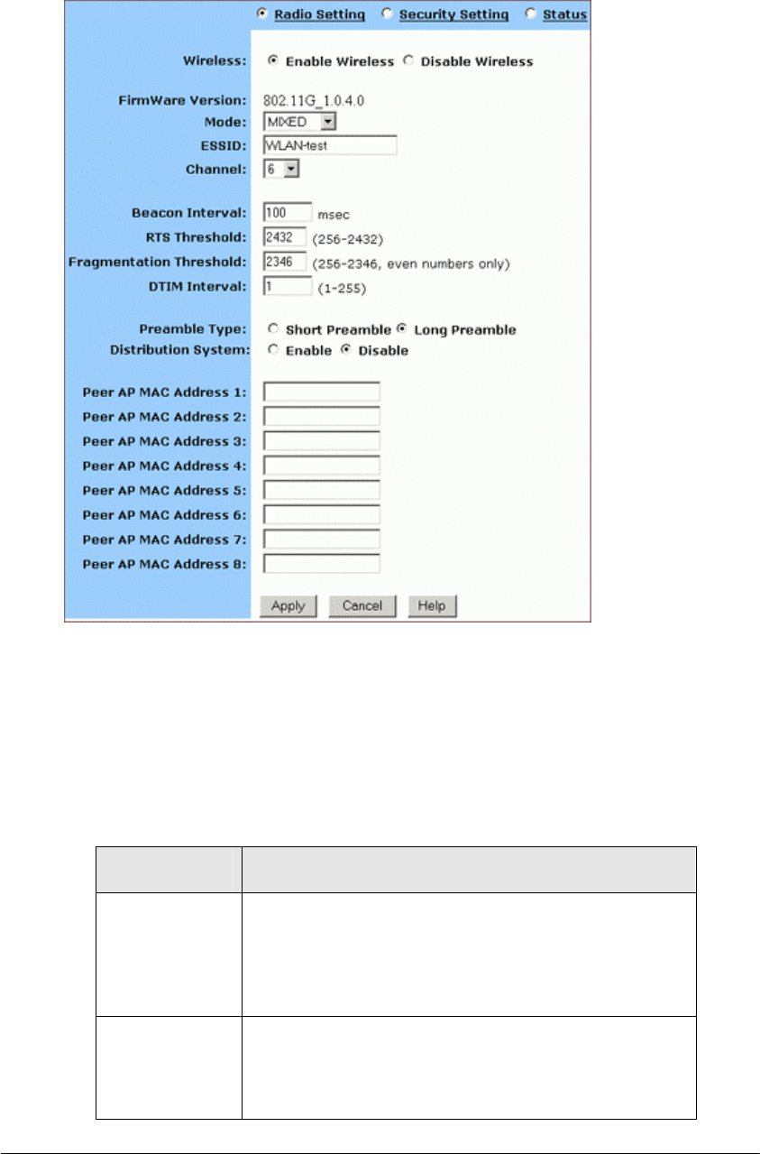
FIGURE 3-7: Wireless – Radio Settings Page
2. Click Enable next to Wireless.
3. Optional. Review the firmware version number and date
information that you are currently using.
4. Enter the following basic radio parameters:
Parameter Description
Mode Selects the Wireless Mode that your Company AP
Router supports from the drop-down list.
Available options are 802.11B, 802.11G, and MIXED
which supports both 802.11B and 802.11G.
ESSID Type the unique identifier for the Extended Service
Set which is shared by client stations in an
infrastructure association, such as WLAN-test.
It is case-sensitive and cannot exceed 32

BASIC FUNCTIONS: WIRELESS
Page 21 of 77
characters.
Channel Selects one IEEE 802.11G channel for wireless LAN
transmissions from the drop-down list.
Specifies the bandwidth which the wireless radio
operates. AP and the client stations that is
associated work in one of channels from 1 to 14.
5. Enter the following advanced radio parameters:
Parameter Description
Beacon Interval Type the time interval in miliseconds between
beacons broadcast by AP (Access Point) in the
Beacon Interval box, such as 100.
RTS Threshold Type a number in the RTS Threshold box.
Also called Request-to-Send Threshold. This field
specifies the minimum size of data frames above
which RTS protocol is used, ranging from 256 to
2432. RTS helps prevent data collision from hidden
nodes.
Fragmentation
Threshold
Type a number in the Fragmentation Threshold box.
For efficiency in high-traffic situations, large files
are split into fragments. This field specifies the
default packet size, an even number ranging from
256 to 2346.
DTIM Interval Type a number in the DTIM Interval box.
Also called Delivery Traffic Indication Map. This
field specifies the number of beacon intervals
between successive DTIMs, ranging from 1 to 255.
Preamble Type Select either Short Preamble (72 bits) or Long
Preamble (144 bits).
Distribution
System
If you want to use Wireless Distribution System on
your Router, click Enable next to Distribution System,
then type the distributed client PCs’ physical
addresses, as described in Step 6.
Otherwise, click Disable.
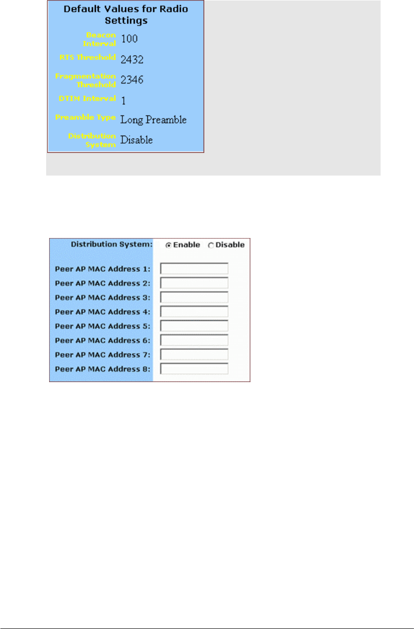
Note - You can see the default values of the above
advanced wireless settings on the right of the page. If you
don’t know how to change the settings, please leave as they
are in Figure 3-8:
BASIC FUNCTIONS: WIRELESS
Page 22 of 77
FIGURE 3-8: Default Values for Radio Settings
6. Optional. If you have enabled Distribution System, type the physical
addresses of distributed client PCs in a wireless network in the Peer
AP MAC Address 1-8 boxes, seen in FIGURE 3-9:
FIGURE 3-9: Peer AP MAC Addresses for Distribution Systems
7. When you have completed editing all the settings, click Apply, or
click Cancel to undo your changes.
To Set Wireless Security Parameters:
1. Click Security Settings on the Wireless page.
The Security Settings appears, seen in FIGURE 3-10:
BASIC FUNCTIONS: WIRELESS
Page 23 of 77
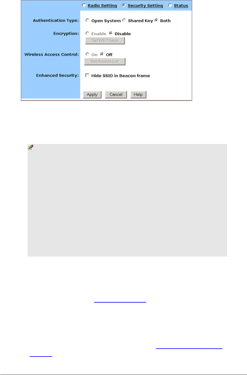
FIGURE 3-10: Wireless – Security Settings Page
2. Select one of Open System, Shared Key and Both from the
Authentication Type drop-down list.
Notes
Authentication Type indicates an authentication algorithm
which can be supported by the Access Point:
▪ Open System: The simplest of available authentication
algorithms. Essentially it is a null algorithm. Any station
that requests authentication with this algorithm may
become authenticated if Open System is set at the
recipient station.
▪ Shared Key: Allows stations with a specific WEP (Wired
Equivalent Privacy) Keys to be authenticated.
▪ Both: Supports the authentications of either stations who
know a shared key or those who do not.
3. If you want to prevent other stations without specific WEP (Wired
Equivalent Privacy) keys from linking to the AP, select Enable next
to Encryption and then click Set WEP Keys to specify relevant keys;
otherwise, select Disable. For detailed instructions on how to set the
WEP Keys, see below To Set WEP Keys.
4. If you want to allow access to the Internet based on user’s MAC
(Media Access Control) address, select On next to Wireless Access
Control and then click Set Access List to specify relevant MAC
addresses; otherwise, click Off. For detailed instructions on how to
specify relevant MAC addresses, see below To Set Wireless Access
Control.
BASIC FUNCTIONS: WIRELESS
Page 24 of 77
5. Next to Enhanced Security, select either Enable or Disable. If you
choose to enable the enhanced security feature, go to Step 6.
6. Optional. If you have enabled Enhanced Security, you can choose to
hide your SSID (Service Set Identifier) in Beacon frame.
7. When you have completed editing all the settings, click Apply, or
click Cancel to undo your changes.
To Set WEP Keys:
1. On the Security Settings page, enable the Encryption and click Set
WEP Keys.
The Set WEP Keys window appears, seen in FIGURE 3-11:
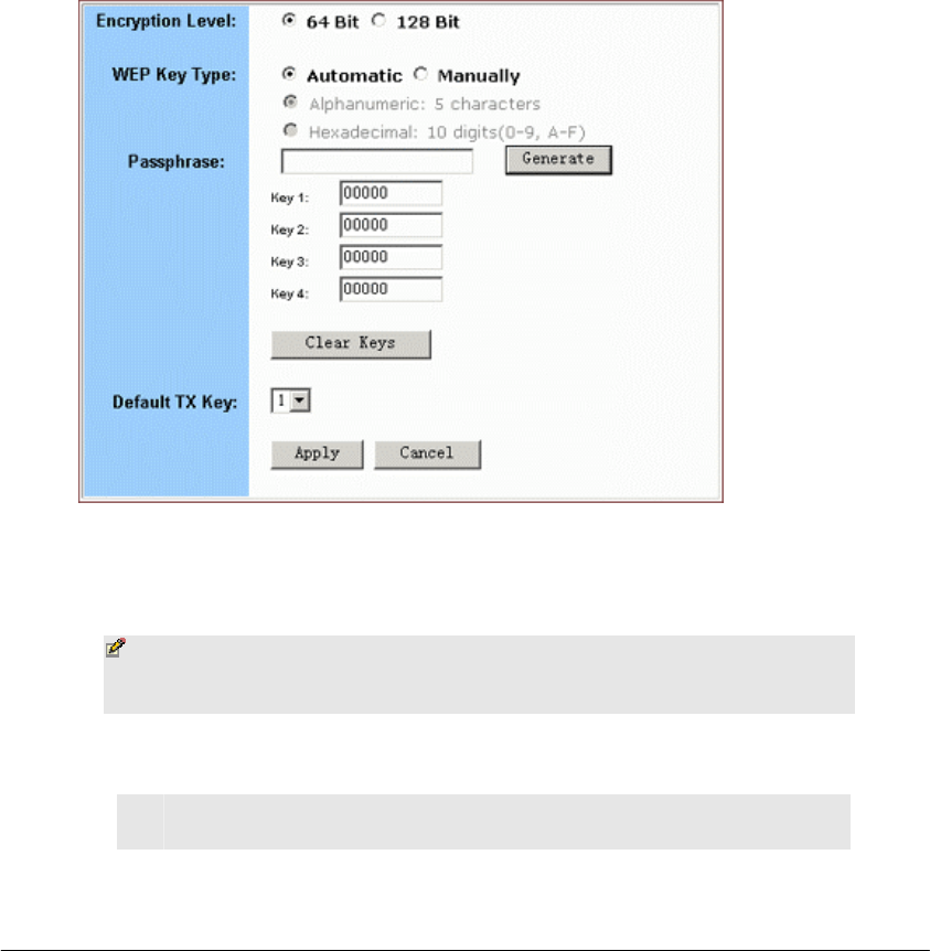
FIGURE 3-11: Set WEP Keys Window
2. Select either 64 Bit or 128 Bit next to Encryption Level.
Note – 128 Bit encryption can provide you a more secure
encryption algorithm, but it will slow down your network
data transmission rates.
3. If you want to generate WEP Keys automatically, do the following:
No. Action
1 Select Automatic next to WEP Key Type.

BASIC FUNCTIONS: WIRELESS
Page 25 of 77
2 Type a string of any words in the Passphrase box, and click
Generate.
Four newly generated WEP Keys will display in
the Key 1 – Key 4.
3 Optional. Click Clear Keys to reset all the keys to null.
Note – Make sure that you write down the passphrase
string, so that you can refer to it if necessary.
4. If you want to enter the key elements manually, do the following:
No. Action
1 Select Manually next to WEP Key Type.
2 If you select Alphanumeric: 5 characters, type a string of 5
alphanumeric characters in the Key 1 – Key 4 boxes
respectively.
3 If you select Hexadecimal: 10 digits (0-9, A-F), type a string
of 10 hexadecimal digits in the Key 1 – Key 4 boxes
respectively.
4 Optional. Click Clear Keys to reset all the keys to null.
5. Select the default encryption key from the Default TX Key drop-
down list, such as Key 1.
6. When you have completed editing all the settings, click Apply, or
click Cancel to undo your changes.
To Set Wireless Access Control:
1. On the Security Settings page, set the Wireless Access Control On
and click Set Access List.
The Window Control List window appears, seen in FIGURE 3-12:
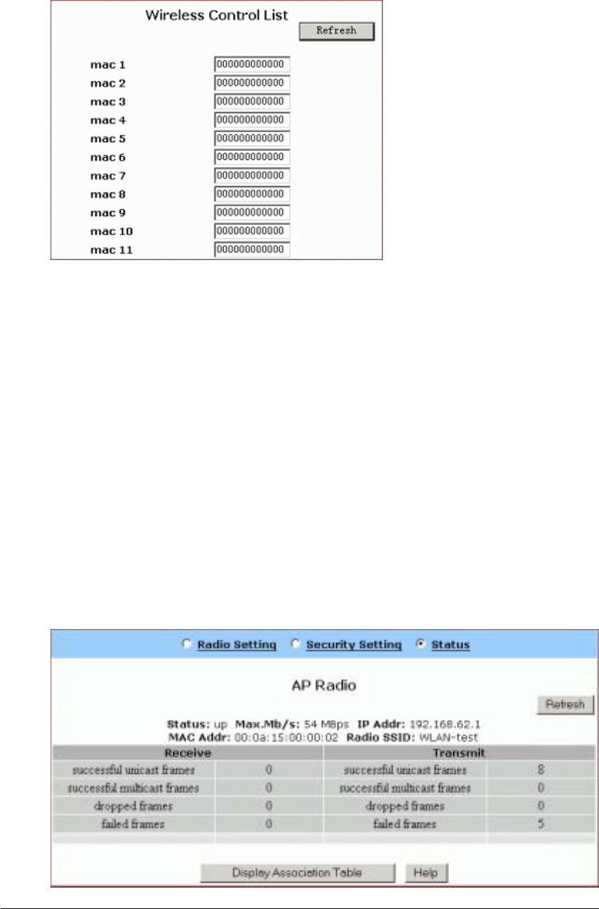
BASIC FUNCTIONS: WIRELESS
Page 26 of 77
FIGURE 3-12: Wireless Control List window
2. Type the MAC addresses that you want to allow to access the
Internet. You can specify up to 80 MAC addresses in the list.
3. When you have complete editing all the MAC addresses, click
Submit, or click Cancel to undo your changes.
4. Optional. You can click Refresh to see the most current MAC
addresses in effect.
To Review Wireless Status:
1. On the Wireless page, select Status.
The Status page appears with your GateWay’s AP Radio
statistics including Status, Max.Mb/s, IP Addr, MAC Addr, Radio
SSID, Receive data and Transmit data. Seen in FIGURE 3-13:
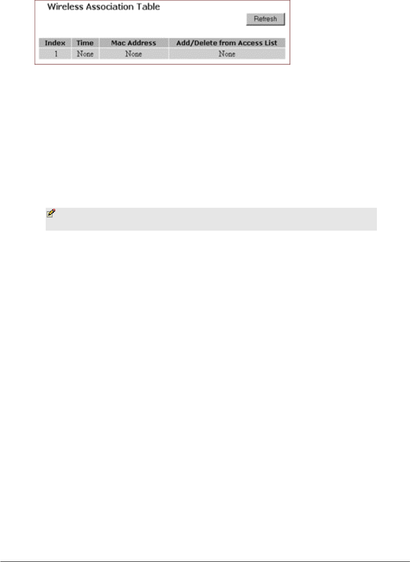
BASIC FUNCTIONS: WIRELESS
Page 27 of 77
FIGURE 3-13: Wireless – Status Page
2. To see the wireless devices of which the AP (Access Point) is aware,
click Display Association Table.
3. Optional. You can click Refresh to see the most current data.
To Disable Wireless:
1. On the Wireless page, select Radio Settings.
The Radio Settings page appears, seen in FIGURE 3-7.
2. If you don’t want the router to support Wireless, select Disable.
Note – None of the router’s wireless functions will work
unless you enable it.

BASIC FUNCTIONS: TOOLS
Page 28 of 77
Tools
On the Tools page, you can:
▪ Change the Administrative Password for Your Router
▪ Restore the Factory Default Configuration
▪ Reset Gateway
▪ Upgrade the Firmware
Important:
▪ We strongly recommend that you change the
administrative password after the first login.
▪ Restoring the default factory settings will reset all of the
router configurations in every page, so we recommend that
you backup the configuration data from the Gateway to
your PC simply using DOS commands. In addition, you can
also restore the factory defaults under the DOS window.
For detailed instructions, see To Backup or Restore the
Configuration Data Using DOS Commands.
▪ If you want to reset the hardware, you need reset the
Gateway.
▪ Before upgrading the firmware, you need download the
firmware image file from the Gateway Web site and save it
to your root local drive first.
To Change the Administrative Password for Your Router:
1. Click Tools on the navigation bar.
The Tools page appears, seen in FIGURE 3-14:
#
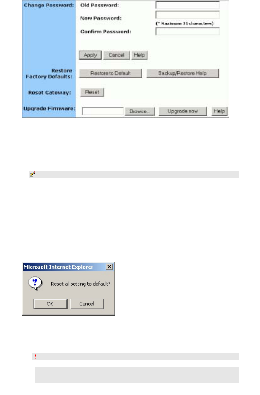
BASIC FUNCTIONS: TOOLS
Page 29 of 77
FIGURE 3-14: Tools Page
2. Type the Old Password in the box. The default password is 1234.
3. Type a New Password in the box.
Note - Password must be less than 64 characters.
4. Type the new password in the Confirm Password box.
To Restore the Factory Default Configuration:
1. On the Tools page, click Restore to Default next to Restore Factory
Defaults.
The Warning dialog box appears, see FIGURE 3-15:
FIGURE 3-15: Warning Dialog Box
2. Click OK.
Important:
▪ Restoring the default factory settings will reset all of the
router configurations in every page, so we recommend that

BASIC FUNCTIONS: TOOLS
Page 30 of 77
you backup the configuration data from the Gateway to
your PC first using DOS commands. For details, see To
Backup or Restore the Configuration Data Using DOS
Commands.
▪ In addition, you can also restore the factory defaults
using DOS commands. For detailed instructions, see To
Backup or Restore the Configuration Data Using DOS
Commands.
To Backup or Restore the Configuration Data Using DOS Commands:
For the backup of the configuration data from the Gateway to your
PC, Gateway acts as a TFTP server.
To backup the configuration data, under the DOS window, use the
following command:
tftp –i gateway_Ip_address GET filename
To restore the configuration data, under the DOS window, use the
following command:
tftp –i gateway_Ip_address PUT filename
gateway_Ip_address: The IP address of the Gateway where you want
to back the configuration data.
filename: The file name for backup from the Gateway. It must begin
with “nvram” which is not case-sensitive, such as “nvram__11032003”.
To Reset Gateway:
If you want to reset the hardware, click Reset next to Reset Gateway on the
Tools page.
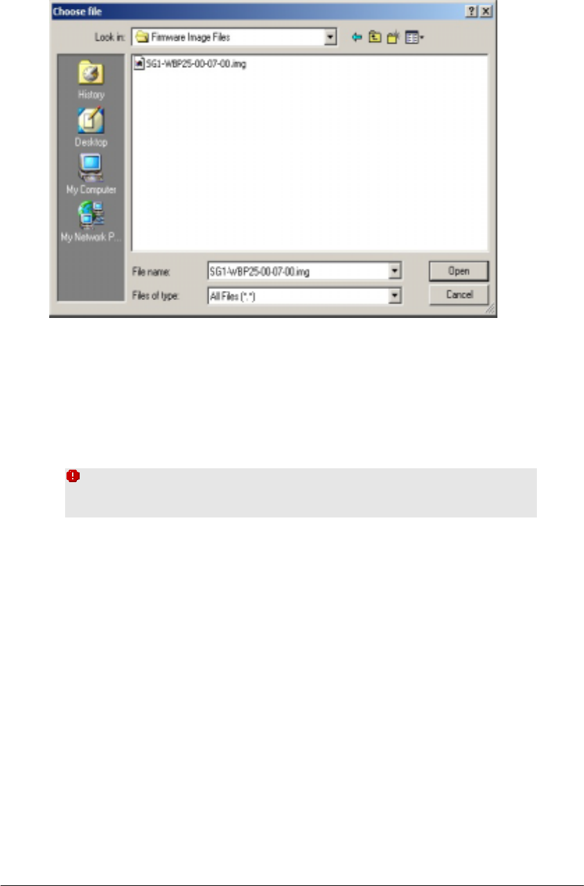
To Upgrade the Firmware:
1. Download a firmware image file from the Gateway Web site and
save it to your root local drive.
2. Type the file path and file name in the Upgrade Firmware box, or
click Browse to launch a Choose file dialog box, seen in FIGURE 3-
15:
BASIC FUNCTIONS: TOOLS
Page 31 of 77
FIGURE 3-15: Choose File Dialog Box for Upgrading Firmware
3. Locate the firmware you have downloaded and click Open.
The Choose file dialog box closes.
4. Click Upgrade Now. The firmware of the device will be upgraded.
Caution – The firmware upgrade may take about 10
seconds, please DONOT power off the unit when it is being
upgraded.
BASIC FUNCTIONS: STATUS
Page 32 of 77
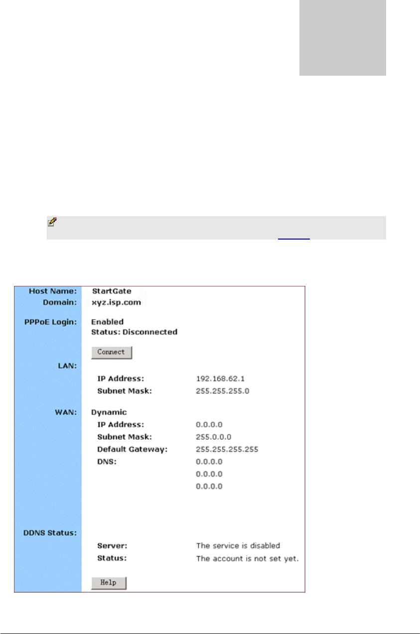
Status
On the Status page, you can view the most current information about your
Router which will be continuously refreshed per 10 seconds, such as Host
Name, Domain, PPPoE Login, LAN/WAN and DDNS Status. Different
configuration may bring you to different data, compared in FIGURE 3-16
and FIGURE 3-17.
Note – If you want to change the configuration, go to the
Setup page. For detailed instructions, see Setup.
▪ If you have enabled the PPPoE Login, the Status page will
display as illustrated in FIGURE 3-16:
FIGURE 3-16: Status Page with PPPoE Login Enabled
q
BASIC FUNCTIONS: STATUS
Page 33 of 77
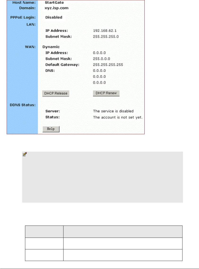
▪ If you have chosen the Dynamic IP and disabled PPPoE
Login, the Status page will display as illustrated in FIGURE 3-
17:
FIGURE 3-17: Status Page with PPPoE Login Disabled
Notes
If you have chosen the Dynamic IP and disabled PPPoE Login,
you can see the DHCP Release and DHCP Renew buttons:
▪ To release the most current WAN IP address, click DHCP
Release.
▪ To renew the WAP IP address, click DHCP Renew.
Status Detail:
Parameter Description
Host Name Shows the name of the device.
Domain Shows the domain name of the device.

BASIC FUNCTIONS: STATUS
Page 34 of 77
PPPoE Login Shows the current status of PPPoE Login:
▪ Disabled
▪ Enabled: Connected, Connecting or Disconnected.
LAN Shows the current IP Address and Subnet Mask of
the device, as seen by users in your internal
network.
WAN Shows the IP Address, Subnet Mask, Default
Gateway, and DNS of the router, as seen by external
users on the Internet.
DDNS Shows the Dynamic DNS Server and Status.
If you want to change the setting, go to the
Advanced Dynamic DNS page. For details
instructions, see To Configure a Dynamic DNS
Server.

BASIC FUNCTIONS: DHCP
Page 35 of 77
DHCP
On the DHCP page, you can set your NAT/Firewall Gateway as a DHCP
(Dynamic Host Configuration Protocol) server, and DHCP servers will
automatically assign IP addresses to all the client PCs in your network.
Notes
▪ If you want to enable DHCP, make sure that there is not
already a DHCP server on your router.
▪ If you don’t enable DHCP on your router, you will need to
manually configure an IP address for each PC in your
network; if you do enable DHCP, make sure that each PC is
configured to receive an IP address automatically.
What do you want to do then?
▪ Set Your Router as a DHCP Server
▪ View the Active IP Table
▪ Disable DHCP on Your Router
To Set Your Router as a DHCP Server:
1. Make sure that there is not already a DHCP server on your router.
2. Make sure that each PC in your network is configured to receive an
IP address automatically.
3. Click DHCP on the navigation bar.
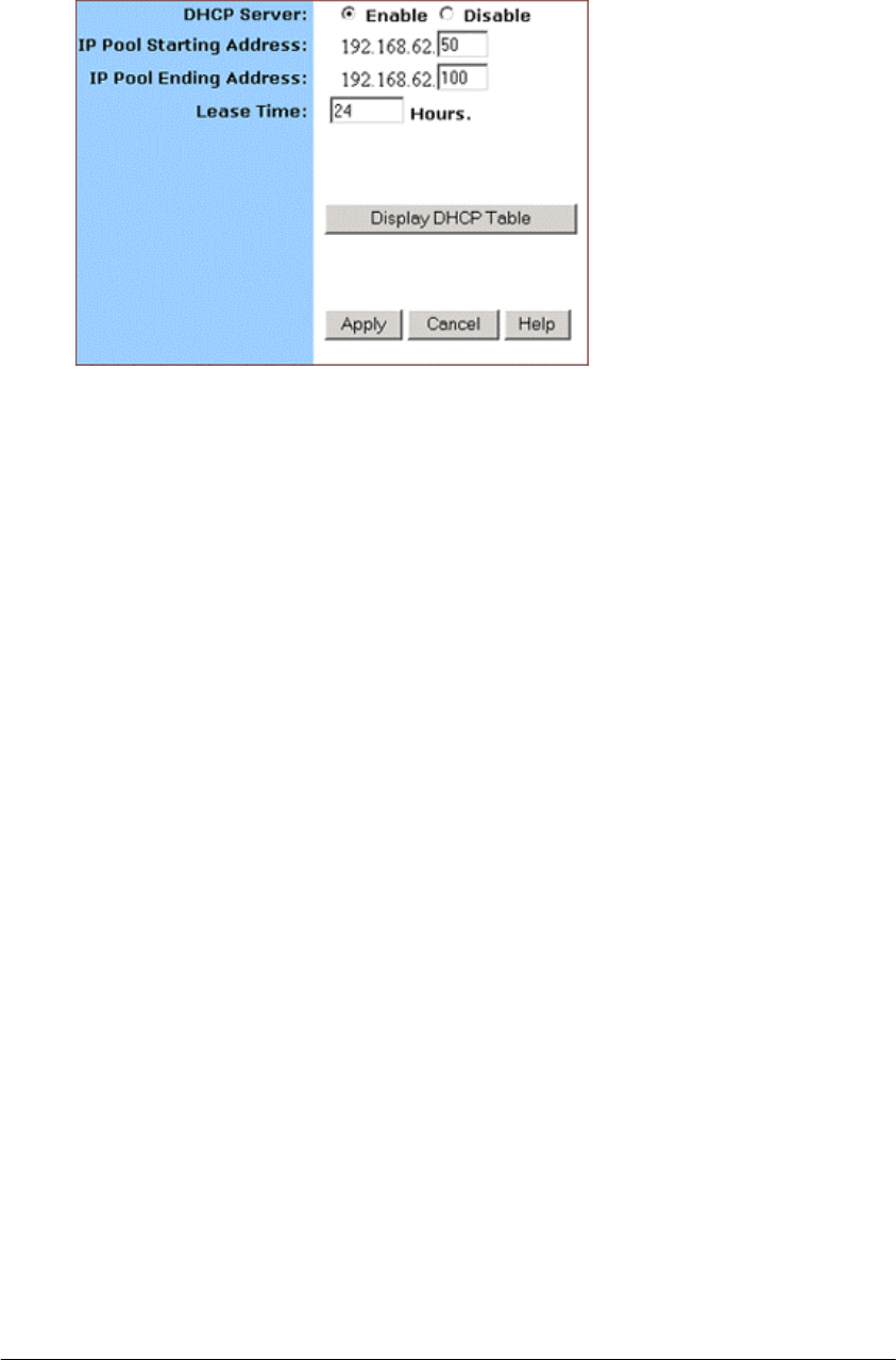
The DHCP page appears, seen in FIGURE 3-18:
¤
BASIC FUNCTIONS: DHCP
Page 36 of 77
FIGURE 3-18: DHCP Page
4. Click Enable next to DHCP Server.
5. Type a IP Pool Starting Address to designate the first IP address that
can be assigned to a PC in your network.
6. Type a IP Pool Ending Address to designate the last IP address that
can be assigned to a PC in your network.
7. When you have completed editing all the settings, click Apply, or
click Cancel to undo your changes.
To Disable DHCP on Your Router:
1. On the DHCP page, click Disabled next to DHCP Server.
2. Click Apply.
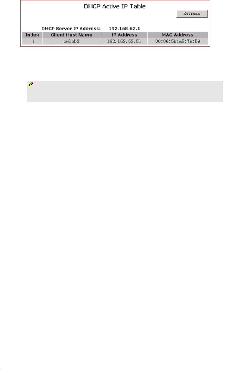
To View the Active IP Table:
1. If you want to find out the information about PCs that have been
assigned IP addresses by the DHCP server, click Display DHCP
Table.
DHCP Server IP Address, Client Host Name, IP Address and
MAC Address for each active client PC will be listed out in the
table, seen in FIGURE 3-19:
BASIC FUNCTIONS: DHCP
Page 37 of 77
FIGURE 3-19: DHCP Active IP Table
2. Optional. Click Refresh to obtain the most current data.
Note – If you have enabled the DMZ and LAN features, you
can also find the relevant information in the DHCP Active IP
Table for DMZ Zone and the DHCP Active IP Table for LAN.
BASIC FUNCTIONS: LOG
Page 38 of 77
Log
On the Log page, you can set up Access Log and view log files that record the
access activity of LAN and WAN client PCs, including Session Event Log,
Block Event Log, Intrusion Event Log and Wireless Event Log.
What do you want to do?
▪ Set up Access Log on Your Router
▪ View Session Event Log
▪ View Block Event Log
▪ View Intrusion Event Log
▪ View Wireless Event Log
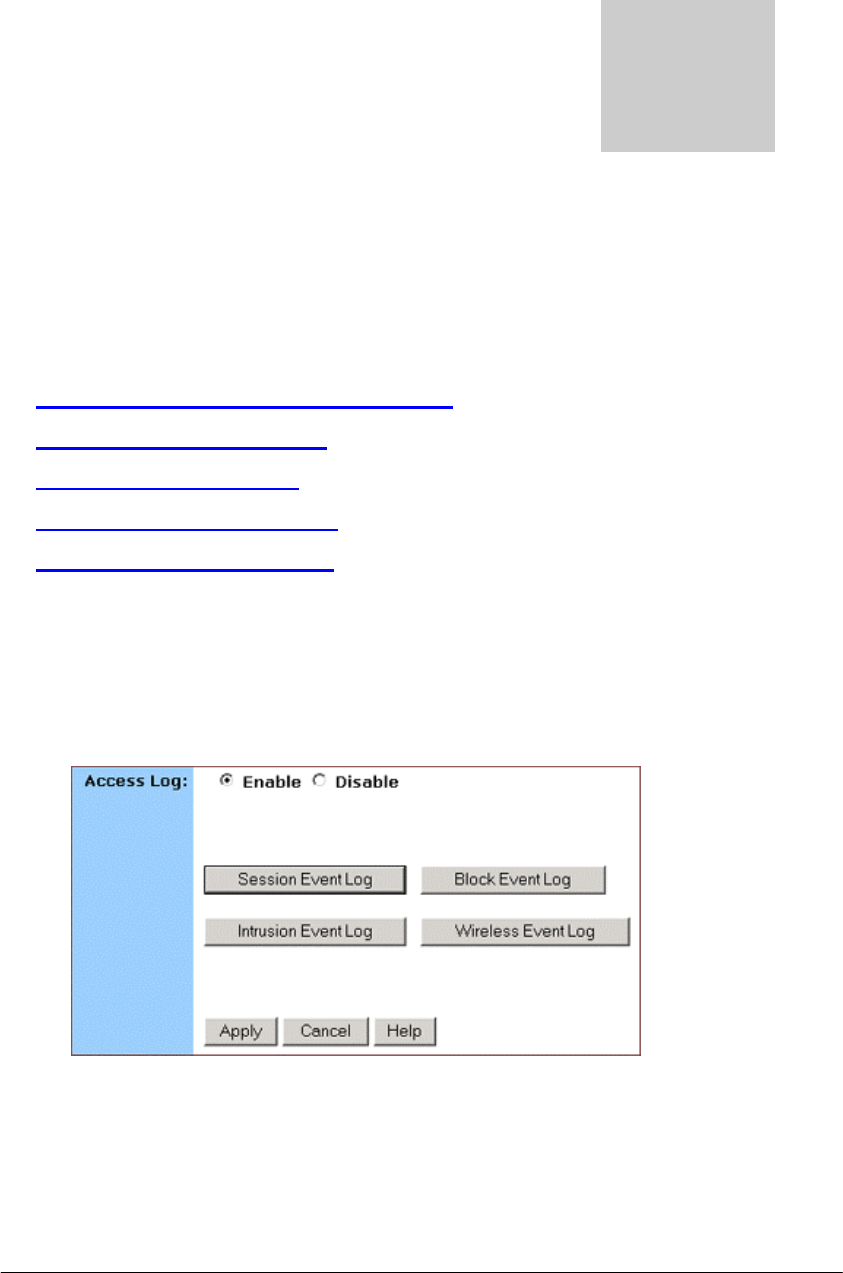
To Set up Access Log on Your Router:
1. Click Log on the navigation bar.
The Log page appears, seen in FIGURE 3-20:
FIGURE 3-20: Log Page
2. Select Enable.
3. Click Apply, or click Cancel to undo your changes.
BASIC FUNCTIONS: LOG
Page 39 of 77
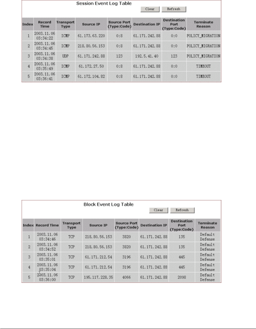
To View Session Event Log:
1. Click Session Event Log on the Log page.
The Session Event Log Table appears, including each session
event entry information like Record Name, Transport type,
Source IP and so on, seen in FIGURE 3-21:
FIGURE 3-21: Session Event Log Table
2. Optional. Click Refresh to obtain the most current data.
3. Optional. Click Clear to delete all the log information.
To View Block Event Log:
1. Click Block Event Log on the Log page.
The Block Event Log Table appears, including each block event
entry information like Record Name, Transport type, Source IP
and so on, seen in FIGURE 3-22:
FIGURE 3-22: Block Event Log Table
2. Optional. Click
Refresh to obtain the most current data.
BASIC FUNCTIONS: LOG
Page 40 of 77
3. Optional. Click Clear to delete all the log information.
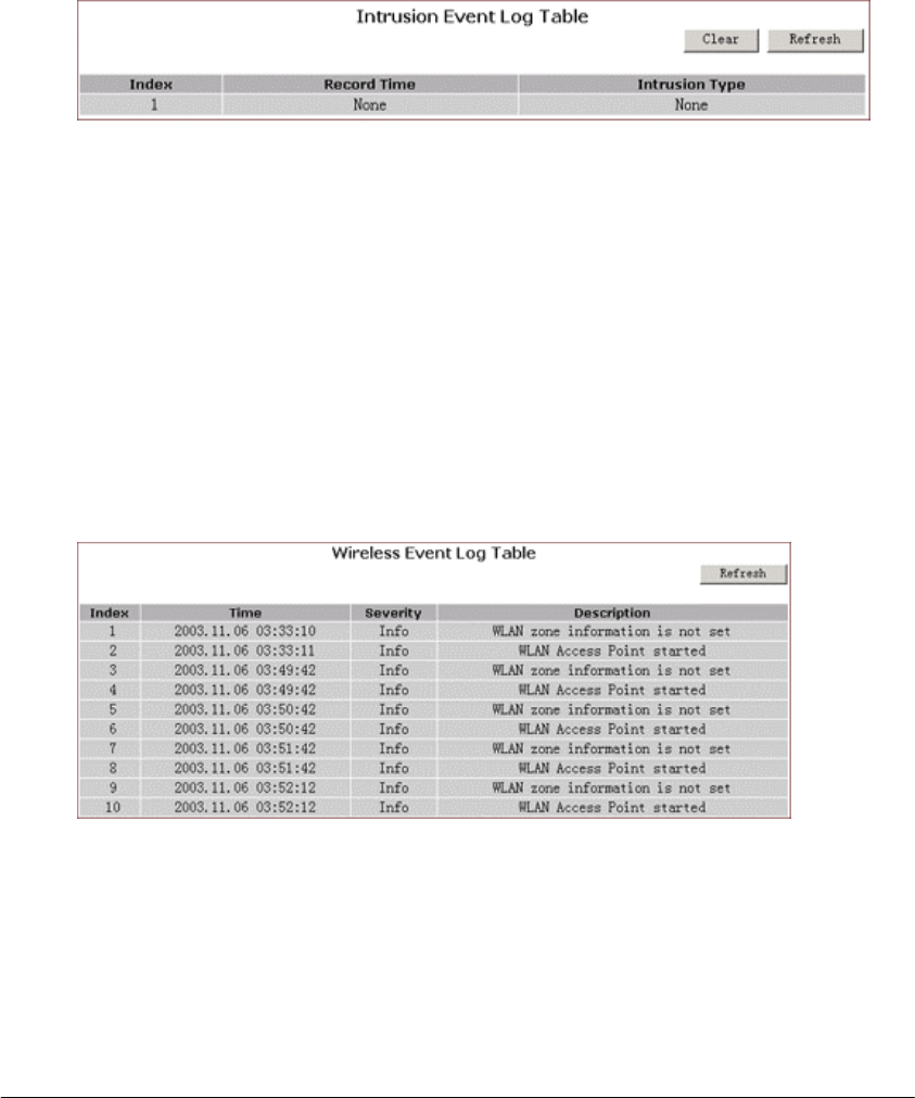
To View Intrusion Event Log:
1 . Click Intrusion Event Log on the Log page.
The Intrusion Event Log Table appears, including each intrusion
event entry’s Record Name and Intrusion Type, seen in FIGURE
3-23:
FIGURE 3-23: Intrusion Event Log Table
2. Optional. Click Refresh to obtain the most current data.
3. Optional. Click Clear to delete all the log information.
To View Wireless Event Log:
1. Click Wireless Event Log on the Log page.
The Session Event Log Table appears, including each wireless
event entry’s Time, Severity and Description, seen in FIGURE 3-
24:
FIGURE 3-24: Wireless Event Log Table
2. Optional. Click Refresh to obtain the most current data.
3. Optional. Click Clear to delete all the log information.
To Disable Access Log on Your Router:

BASIC FUNCTIONS: LOG
Page 41 of 77
1. On the Log page, click Disabled next to Access Log.
2. Click Apply.

BASIC FUNCTIONS: STATISTICS
Page 42 of 77
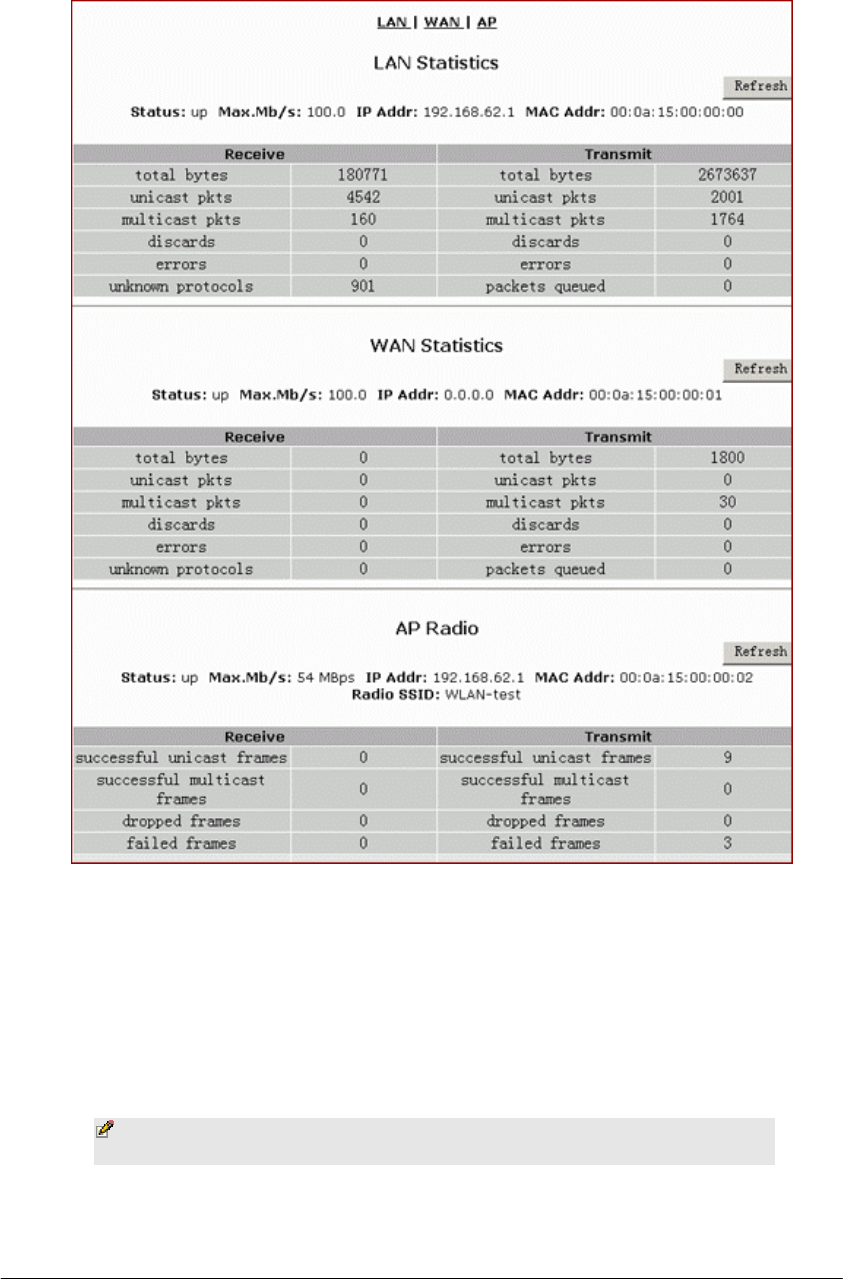
Statistics
On the Statistics page, you can view the statistics information of LAN, WAN
and AP (Access Point) Radio ports, including Status, Max.Mb/s, IP Addr and
MAC Addr, Receive data and Transmit data.
You can click Statistics on the navigation bar, and then the Statistics page
appears, seen in FIGURE 3-25:
L
BASIC FUNCTIONS: STATISTICS
Page 43 of 77
FIGURE 3-25: Statistics Page
The Statistics page includes three parts:
▪ LAN Statistics: Lists out the data on the LAN port.
▪ WAN Statistics: Lists out the data on the WAN port.
▪ AP Radio: Lists out the data on the Access Point’s radio.
Note - You can also click Refresh in any part above to
obtain the most current data.

BASIC FUNCTIONS: PRINTER
Page 44 of 77
Printer
The Print Server is designed to provide simple and efficient printer sharing.
All users on the LAN, regardless of operating system or network protocol,
will be able to use the printers connected to the Printer Server. By connecting
your printer to a Print Server instead of a file server or workstation, you will
offload system resources, increase printing performance and allow different
network protocols to be used simultaneously.
On the Printer page, you can set up a Printer Server and configure its
settings for printing share.
What do you want to do then?
▪ Set up the Print Server on Your Router
▪ View the Printing Task Queue
▪ Disable the Print Server on Your Router
To Set up the Print Server on Your Router:
1. Click Printer on the navigation bar.
The Printer page appears, seen in FIGURE 3-26:
¬
BASIC FUNCTIONS: PRINTER
Page 45 of 77
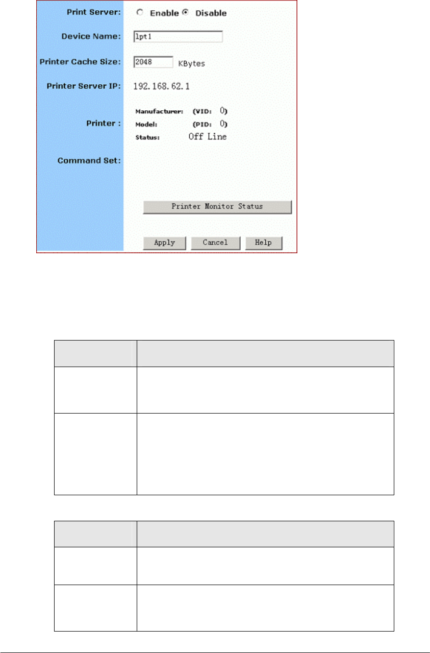
FIGURE 3-26: Printer Page
2. Select
Enable next to Print Server.
3. Enter the following information in the boxes:
Parameter Description
Device Name Unique name of the print server hardware used for
identification purposes. Client PCs in the network
will use it as printing queue name.
Printer Cache
Size
Used for system evaluation. If the printer does not
work properly, you may argument this value, such
as 4096, 8192.
The same value as your printer supports is
recommended.
4. Review the relevant information:
Parameter Description
Printer Server
IP
Shows the IP address of the Printer Server. It
equals to the LAN IP address.
Printer Shows the Manufacturer and VID (Vendor ID), Model
and PID (Product ID) and Status of the current
printer connected to the device’s USB port.
BASIC FUNCTIONS: PRINTER
Page 46 of 77
Command Set Shows the command set of the printer, i.e., when a
printer is connected to the print server, it will
display here.
5. When you have completed editing all the settings, click Apply, or click
Cancel to undo your changes.
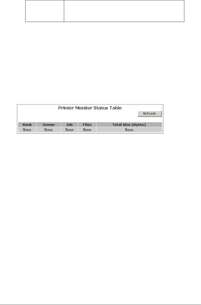
To View the Printing Task Queue:
1. On the Printer page, click Printer Monitor Status.
The Printer Monitor Status Table appears, seen in FIGURE 3-27:
FIGURE 3-27: Printer Monitor Status Table
2. Optional. Click Refresh to see the most current printing tasks.
To Disable the Print Server on Your Router:
1. On the Printer page, click Disable next to Print Server.
2. Click Apply.

ADVANCED FUNCTIONS
Page 47 of 77
T
Advanced Function
In this chapter, you will learn how to use the advanced
administrative functions that the Company AP Router provides,
including Virtual Server, Filters, IP/URL Block, Special Apps,
DMZ Host, MAC Clone, Dynamic DNS, Proxy DNS and SNMP.
he Web-based Administration Tool provides you some advanced
services on the Advanced Function navigation bar, such as Filtering
and cloning your MAC addresses.
In most cases, basic functions are Okay. If you want to set the
advanced configuration, you will need to toggle to the Advanced Function
navigation bar first.
To Toggle between Basic Functions and Advanced Functions:
1. To toggle to the Advanced window, click Advanced on the right side
of the Basic window, seen in FIGURE 4-1:
FIGURE 4-1: Advanced Button on the Basic Window
2. Once you are already in the Advanced window, click Basic on the
right side of the Advanced window to return to the Basic Window,
seen in FIGURE 4-2:
FIGURE 4-2: Advanced Button on the Basic Window
Chapter
4

ADVANCED FUNCTIONS: VIRTUAL SERVERS
Page 48 of 77
Virtual Servers
In some situations, you might want users on the Internet to be able to access
servers on your LAN, such as an FTP Server, Telnet Server or Web Server.
Such remote services are accomplished by creating Virtual Server.
Each virtual server has its own IP address and shares a single public IP
address. It is defined by the Protocol type (TCP, UDP or Both) and a
TCP/UDP/Both port number. Only the enabled virtual servers can be
accessed by remote users over the Internet.
Note - Configuring virtual servers may cause filters to be
automatically created on the Filters page.
What do you want to do?
▪ Set up a Client PC on the LAN as a Virtual Server
▪ Delete Virtual Servers on the LAN
To Set up a Client PC on the LAN as a Virtual Server:
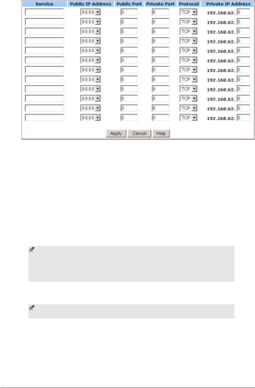
1. On the Advanced navigation bar, click Virtual Servers.
The Virtual Servers page appears with a list of existing virtual
servers, seen in FIGURE 4-3:
¡
ADVANCED FUNCTIONS: VIRTUAL SERVERS
Page 49 of 77
FIGURE 4-3: Virtual Servers Page
2. If you have enabled DMZ and your Gateway is not configured to
retrieve an IP address automatically, select either of the following
options from the Choose Interface drop-down list:
(1) External – Internal: To set up Virtual Server in your LAN network.
(2) External – DMZ: To set up Virtual Servers in your DMZ network.
3. If you are using the Windows XP operating system, type a remote
service name in the Service box.
Note – It is only available for client PCs using Windows XP.
Because Windows XP takes an advantage of the UPnP
(Universal Plug and Play) feature of the Company AP Router,
it allows client PCs that support UPnP to identify the router
automatically.
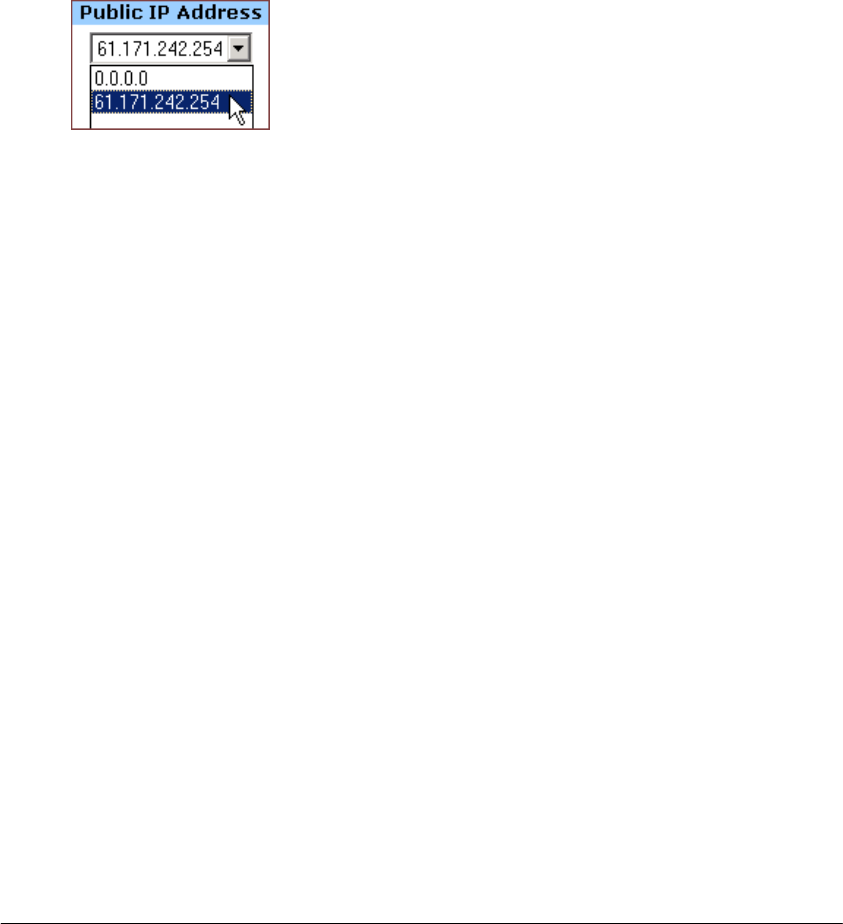
4. Select a Public IP Address from the drop-down list.
Note – The IP Address of a DMZ host will not appear in the
list.
5. Type a port number in the Public Port and Private Port boxes, such as
80 for HTTP. For help on which port to choose, refer to Well-known
Ports on the right of the page, seen in FIGURE 4-4:

ADVANCED FUNCTIONS: VIRTUAL SERVERS
Page 50 of 77
FIGURE 4-4: Well-know Ports
Notes
▪ Public Port is the TCP/UDP/Both port number used by the
server PC on the WAN. It is also called the external port
number because this port number is visible to the users on
the Internet.
▪ Private Port is the TCP/UDP/Both port number used by the
server PC on the LAN. The designated Public Port will be
translated into this internal port number.
6. Select one of TCP, UDP and Both from the Protocol drop-down list.
7. Type a local IP address of the server PC on the LAN in the Private IP
Address box.
8. When you have completed editing all the settings, click Apply, or click
Cancel to undo your changes.
To Delete Virtual Servers on the LAN:
1. On the Advanced navigation bar, click Virtual Servers.
A list of existing virtual servers appears.
2. For any virtual server you want to delete, select 0.0.0.0 from the Public
IP Address drop-down list.
3. Click Apply.

ADVANCED FUNCTIONS: FILTER
Page 51 of 77
Filters
On the Filters page, you can set up filters that can selectively allow traffic to
pass in and out of your network. The Company AP Router comes with 9
factory default filters for you.
In addition to 9 default filters, some filters may be created automatically to
allow Virtual Servers or Special Applications to function.
We strongly recommend that you choose an empty row when you want to set
up new filters, because overwriting or deleting these filters may cause some
services to be disabled, for example, your client PCs may NOT be able to
access the Internet.
Note – If you have overwritten or deleted the factory
default filters, you can retrieve them at a later time using the
Restore Factory Defaults function on the Tools page. For
detailed instructions, see To Restore the Factory Default
Configuration.
What do you want to do?
▪ Set up a Port Filtering or Raw IP Filter
▪ Delete a Port Filtering or Raw IP Filter
To Set up a Port Filtering or Raw IP Filter:
1. On the Advanced navigation bar, click Filters.
The Filters page appears, seen in FIGURE 4-5:
±
ADVANCED FUNCTIONS: FILTER
Page 52 of 77
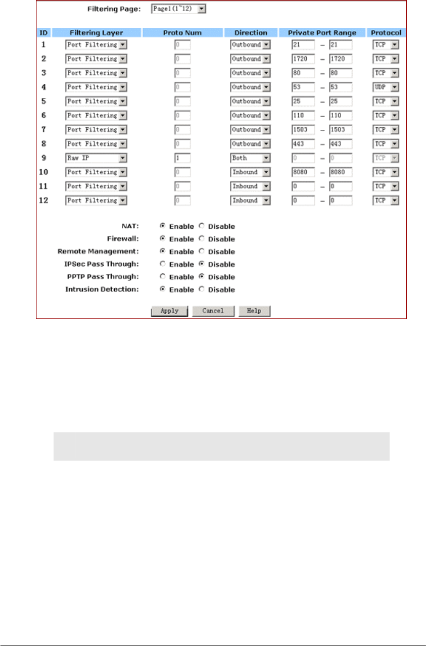
FIGURE 4-5: Filters Page
2. Select an option from the Filtering Page drop-down list: 1~12, 13~24,
25~36.
3. If you select Port Filtering from the Filtering Layer drop-down list, do
the following:
No. Action
1 Select a traffic direction from the drop-down list: Inbound,
Outbound and Both.
2 Type the start port number and end port number that you
want to allow in the Private Port Range boxes.
3 Select a protocol type from the drop-down list: TCP, UDP
and Both.
4. If you select Raw IP from the Filtering Layer drop-down list, do the
following:

ADVANCED FUNCTIONS: FILTER
Page 53 of 77
No. Action
1 Type an IP Protocol Number in the Proto Num box.
Note - It ranges from 0 to 255, but can not
be 6 (TCP) or 17 (UDP); otherwise, this port
filter will not work.
2 Select a traffic direction from the drop-down list: Inbound,
Outbound and Both.
3 Select an option from the Protocol drop-down list: TCP,
UDP and Both.
5. Optional. Select Enable or Disable for the following additional filtering
options:
Parameter Description
NAT Allows you to set up NAT (Network Access
Translation).
Firewall Allows you to protect your network with a firewall.
Remote
Management
Allows you to access your router’s Web-based
Administration Tool through your WAN connection.
IPSec Pass
Through
Allows you to use IP Security Pass Through.
PPTP Pass
Through
Allows you to use PPTP (Point-to-Point Tunneling
Protocol), used to enable VPN sessions.
Intrusion Detect Allows you to detect and record intrusion attempts
into your network.
6. When you have completed editing all the settings, click Apply, or click
Cancel to undo your changes.
To Delete Filters:
You can delete any existing Port Filtering or Raw IP filer, but make sure that
you are deleting an unwanted one, otherwise deleting the filters associated
with Virtual Servers or Special Applications may cause to services to collapse
down.

ADVANCED FUNCTIONS: FILTER
Page 54 of 77
To Delete a Port Filtering Filter:
1. On the Filters page, for any Raw IP filter you want to delete, type 0 in
the Private Port Range boxes.
2. Click
Apply.
To Delete a Raw IP Filter:
1. On the Filters page, for any Raw IP filter you want to delete, type 0 in
the Proto Num box.
2. Click Apply.

ADVANCED FUNCTIONS: IP BLOCK
Page 55 of 77
IP/URL Block
On the IP/URL Block page, you can create filters that can selectively block
users from specific IP addresses and domain names to pass in and out of
your network. The Company AP Router provides two ways of blocking users:
▪ IP Block: Allows you to block a single IP address or a range
of IP addresses.
▪ URL Block: Allows you to block up to 36 domain names.
Note – This IP/URL Block feature will block in both
directions from specified IP addresses or domain names.
What do you want to do?
▪ Block a Single IP Address
▪ Block a Range of IP Address
▪ Block a Specific Domain Name
▪ Delete a Specific or All IP Blocks
▪ Delete a Specific or All URL Blocks
To Block a Single IP Address:
1. Do either of the following:
▪ Click IP/URL Block on the Advanced navigation bar.
▪ If you are on the URL Block page, select IP Block on the upper
of the page.
The IP Block page appears, seen in FIGURE 4-6:
[

ADVANCED FUNCTIONS: IP BLOCK
Page 56 of 77
FIGURE 4-6: IP Block Page
2. In Line 1 – Line 6, type the same IP addresses in both IP Block
Starting Address and IP Block Ending Address boxes respectively.
3. Optional. You can click Clear All to conveniently delete all the existing
IP addresses and then do Step 2.
4. When you have completed editing all the IP addresses you want to
block, click Apply, or click Cancel to undo your changes.
To Block a Range of IP Address:
1. Do either of the following:
▪ Click IP/URL Block on the Advanced navigation bar.
▪ If you are on the URL Block page, select IP Block on the upper
of the page.
The IP Block page appears, seen in FIGURE 4-6.
2. In Line 1 – Line 6, type the different IP addresses in both IP Block
Starting Address and IP Block Ending Address boxes respectively.
3. Optional. You can click Clear All to conveniently delete all the existing
IP addresses and then do Step 2.
4. When you have completed editing all the IP addresses you want to
block, click Apply, or click Cancel to undo your changes.
To Block a Specific Domain Name:
ADVANCED FUNCTIONS: IP BLOCK
Page 57 of 77
1. Click IP/URL Block on the Advanced navigation bar.
The IP Block page appears, seen in FIGURE 4-6.
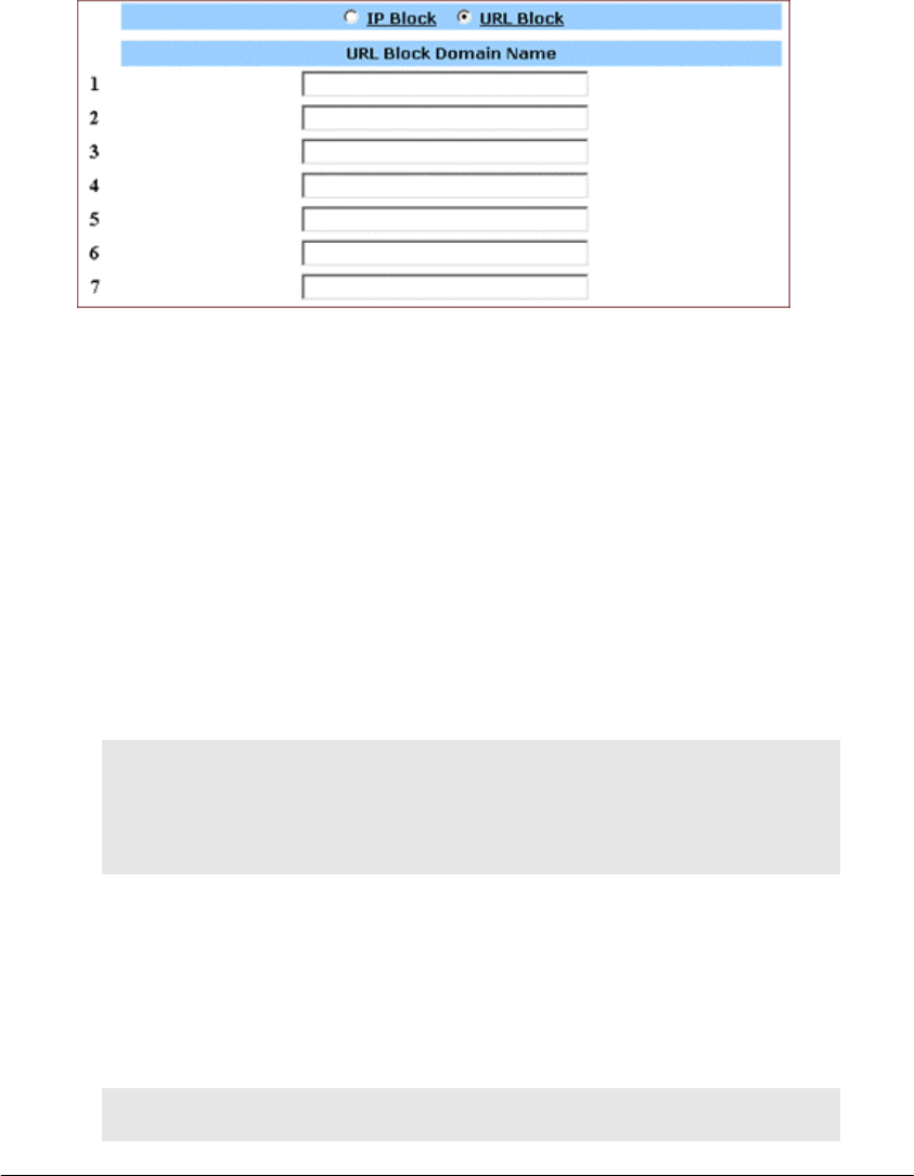
2. Select URL Block on the IP Block page.
The URL Block page appears, seen in FIGURE 4-7:
FIGURE 4-7: URL Block Page
3. In Line 1 – Line 36, type the URLs you want to block.
4. Optional. You can click Clear All to conveniently delete all the existing
URLs and then do Step 2.
5. When you have completed editing all the domain names you want to
block, click Apply, or click Cancel to undo your changes.
To Delete a Specific or All IP Blocks:
1. On the IP Block page, do either of the following:
▪ For any IP block you want to delete, type 0.0.0.0 in both IP
Block Starting Address and IP Block Ending Address boxes
respectively.
▪ If you want to delete all IP blocks, click Clear All.
2. Click Apply.
To Delete a Specific or All URL Blocks:
1. On the URL Block page, do either of the following:
▪ For any domain name block you want to delete, clear out
the URL in the box.

ADVANCED FUNCTIONS: IP BLOCK
Page 58 of 77
▪ If you want to delete all URL blocks, click Clear All.
2. Click Apply.

ADVANCED FUNCTIONS: SPECIAL APPS
Page 59 of 77
Special Apps
On the Special Apps page, you can authorize certain ports to communicate
with PCs outside your network. It may be necessary for multi-session
applications, such as online games and voice conferencing.
There are two ways of set up new special applications on your router:
▪ Popular Application Copy: Allows you to select one of
frequently used applications from the Popular Applications
drop-down list and copy it to your Special Application Table.
Available options are AIM, Diablo II (1), Diablo II (2), StarCraft,
StarCraft III, ICUII, FTP, CUseeMe, MSN Messenger and Real
Player.
▪ Manual Configuration: If the application you want to configure
is not in the Popular Applications list, you can configure its
settings manually.
Before configuring a new special application, would you please check the list
of those popular applications first? If it is already in the list, we recommend
that you use the Popular Application Copy unless you know exactly which
settings to choose.
Notes
▪ Configuring special applications may cause filters to be
automatically created on the Filters page.
▪ The Company AP Router provides two factory default
special applications for FTP and NetMeeting, if you
overwrite them or any other existing application, they will
not work.
What do you want to do?
▪ Copy a Popular Application to a Specific Line
▪ Configure a Special Application Manually
▪ Delete Special Applications
ADVANCED FUNCTIONS: SPECIAL APPS
Page 60 of 77
To Copy a Popular Application to a Specific Line:
1. On the Advanced navigation bar, click Special Apps.
The Popular Applications list appears on the Special Apps page,
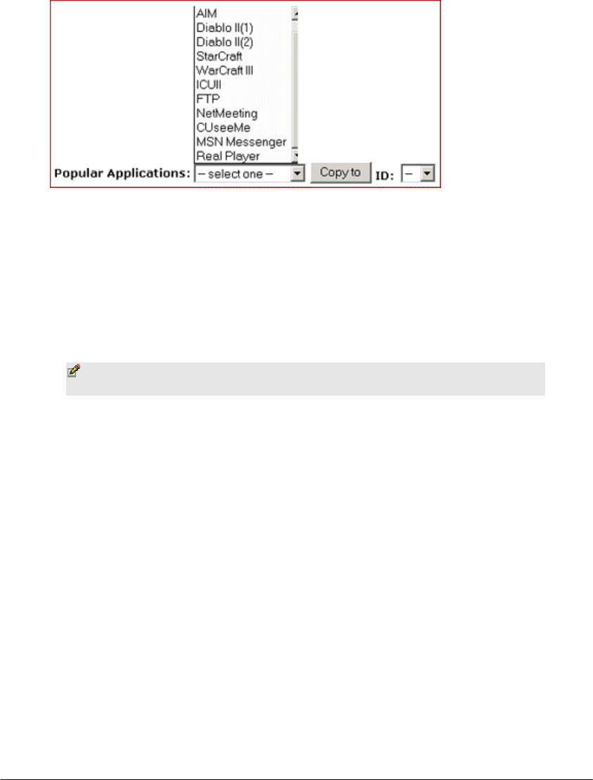
seen in FIGURE 4-8:
FIGURE 4-8: Popular Applications List
2. Select an option from the Popular Applications drop-down
list, including AIM, Diablo II (1), Diablo II (2), StarCraft,
StarCraft III, ICUII, FTP, CUseeMe, MSN Messenger and
Real Player.
3. Select a specific line number from the ID drop-down list.
Note – Make sure the specified ID presents an empty line
unless you want to overwrite an existing application.
4. Click Copy to.
The selected application’s configuration is added to your
Special Applications Table on the upper of the page.
5. When you have completed editing all the settings, click Apply, or click
Cancel to undo your changes.
To Configure a Special Application Manually:
1. On the Advanced navigation bar, click Special Apps.
The Special Apps page appears, seen in FIGURE 4-8:
ADVANCED FUNCTIONS: SPECIAL APPS
Page 61 of 77
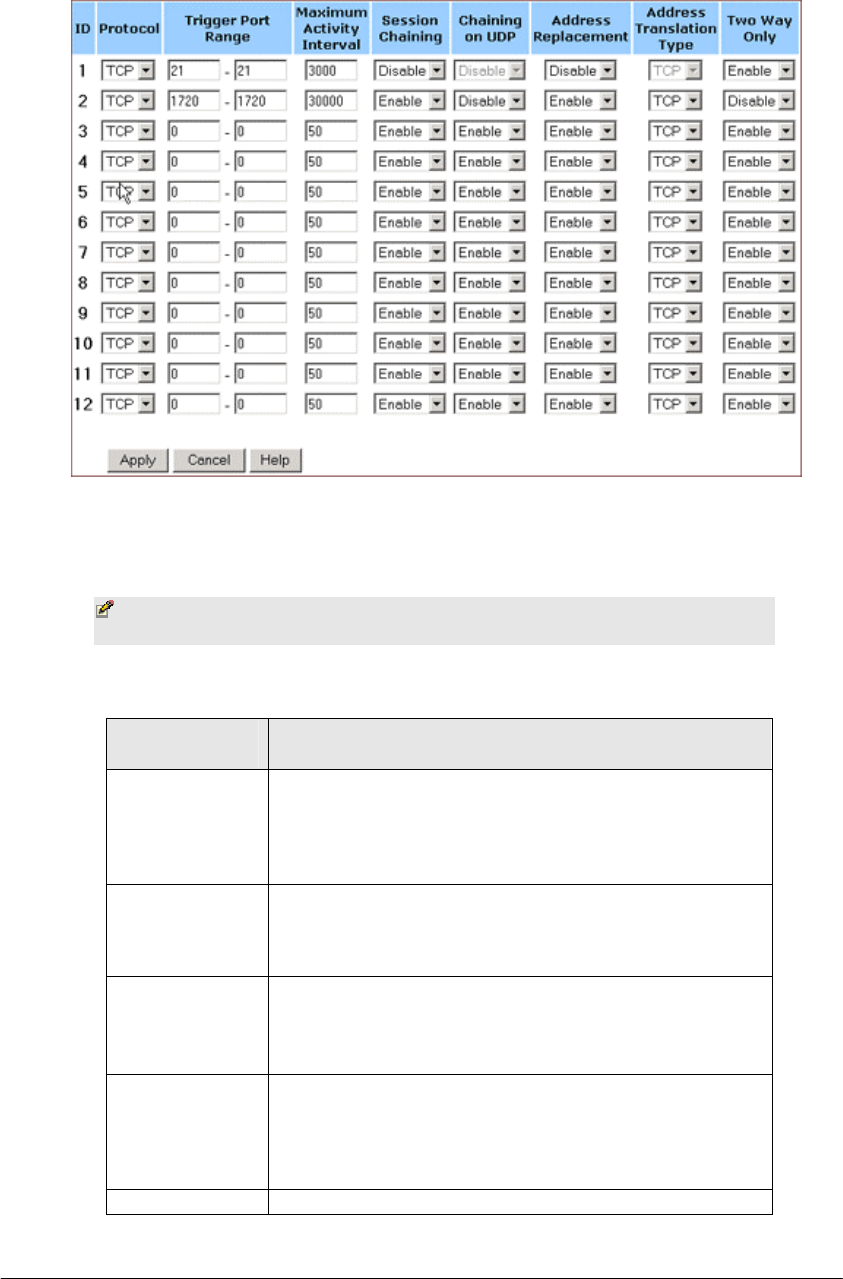
FIGURE 4-8: Special Apps Page
2. Select a line corresponding to a specific ID.
Note – Make sure you have selected an empty line unless
you want to overwrite an existing application.
3. Enter the following configuration information:
Parameter Description
Protocol Specifies the communication protocol used by the
application.
Available options are TCP, UDP and Both.
Trigger Port
Range
Range of ports used for outgoing traffic. It will
trigger the Gateway to accept certain incoming
requests.
Maximum
Activity
Interval
Maximum number of miliseconds after the port
trigger function, within which incoming requests
will be accepted.
Session
Chaining
Allows you to select either Enable or Disable.
Specifies whether dynamic sessions can be
chained, allowing multi-session triggering.
Chainin
g
on Allows you to select Enable or Disable only when

ADVANCED FUNCTIONS: SPECIAL APPS
Page 62 of 77
UDP Session Chaining is enabled.
Specifies whether the session chaining is allowed
on UDP.
Address
Replacement
Allows you to select Enable or Disable only when
Chaining on UDP is enabled.
Specifies whether binary address replacement
should be performed.
Address
Translation
Type
Allows you to select TCP or UDP only when
Address Replacement is enabled.
Specifies whether address translation is performed
on TCP or UDP packets.
Two Way Only Allows you to select either Enable or Disable.
Specifies that a new session is allowed to be
initiated from the same remote host.
4. When you have completed editing all the settings, click Apply, or click
Cancel to undo your changes.
To Delete Special Applications:
1. On the Special Apps page, for any application you want to delete, type
0 – 0 in the Trigger Port Range box.
2. Click Apply.
ADVANCED FUNCTIONS: DMZ HOST
Page 63 of 77
DMZ Host
On the DMZ Host page, you can expose one or more client PCs in your
network to the Internet. It is often used for online games that require
unstricted two-way communications.
The total number of DMZ (Demilitarized Zone) hosts you can have depends
on how many Global Addresses you have configured on the Global Address
page. For example, if you have defined 5 Global Addresses (including the
default IP), you are limited to 5 DMZ hosts. Since the maximum number of
Global Addresses is 8, the total number of DMZ hosts you can configure is
also 8.
Caution – Once a PC in your network is designated as DMZ
host, it will not have any firewall protection.
What do you want to do?
▪ Designate a PC in Your Network as a DMZ Host
▪ Delete DMZ Hosts
To Designate a PC in Your Network as a DMZ Host:
1. On the Advanced navigation bar, click DMZ Host.
The DMZ Host page appears, seen in FIGURE 4-9:
FIGURE 4-9: DMZ Host Page
¦
ADVANCED FUNCTIONS: DMZ HOST
Page 64 of 77
2. Select a Public IP Address from the drop-down list.
3. Type the IP address of a PC in your network that you want to
designate as a DMZ Host in the Private IP Address box.
4. When you have completed editing all the settings, click Apply, or click
Cancel to undo your changes.
To Delete DMZ Hosts:
1. On the DMZ Host page, for any DMZ host you want to delete, select
0.0.0.0 from the Public IP Address drop-down list.
2. Click Apply.
ADVANCED FUNCTIONS: MAC CLONE
Page 65 of 77
MAC Clone
If your ISP restricts services at a PC level, using MAC Clone, you can copy a
PC MAC (Media Access Control) address to the router. Then what story will
begin? The router will appear as a single PC, and multiple PCs in your
network will access the Internet via this “Single PC”.
To Clone the MAC Address:
1. On the Advanced navigation bar, click MAC Clone.
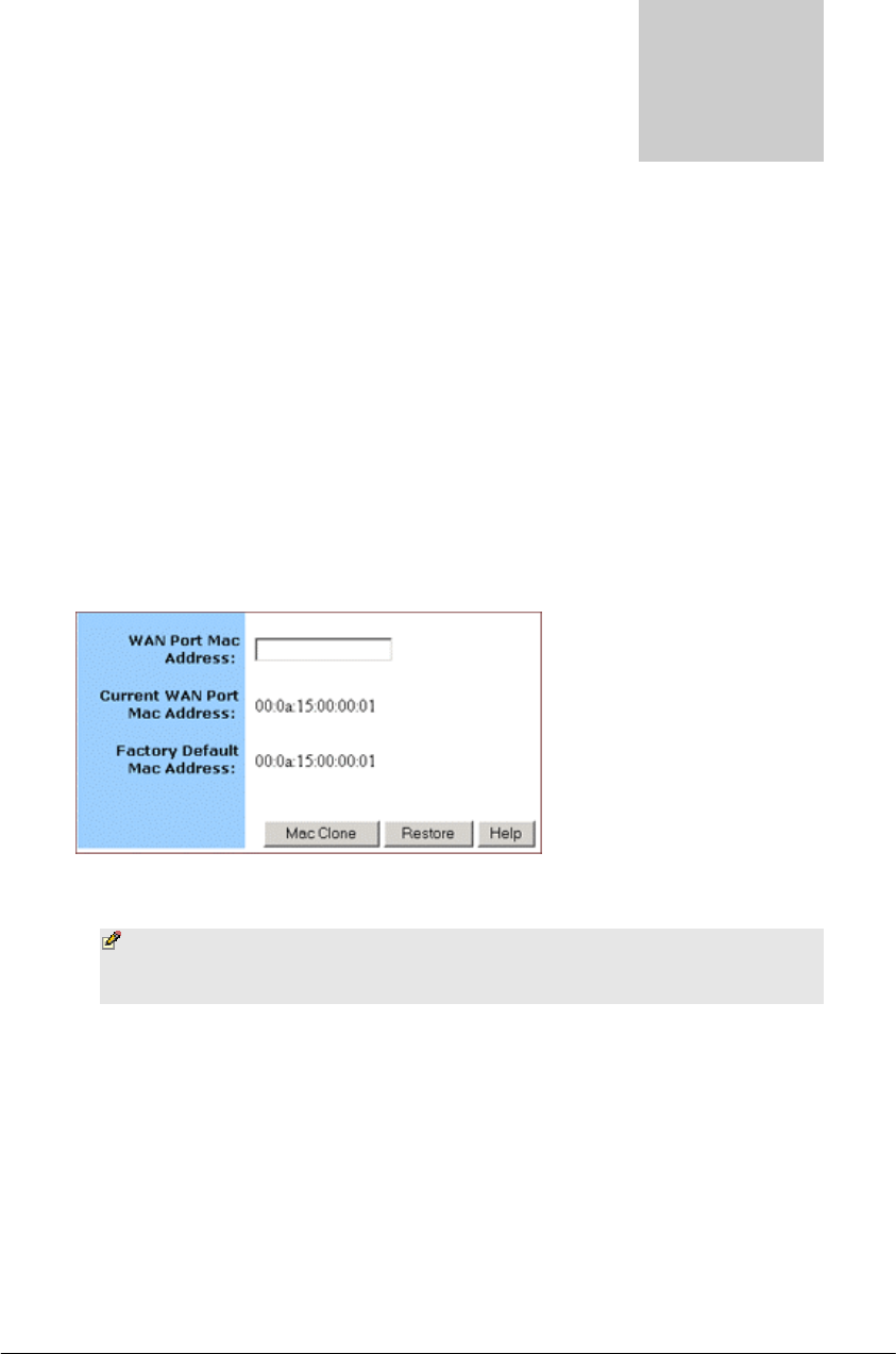
The MAC Clone page appears with the current WAN port
address and the factory default MAC address for your
convenience, seen in FIGURE 4-10:
FIGURE 4-10: MAC Clone Page
Note – You may need to use the Ethernet MAC address of
the NIC (Network Interface Card) that your PC is registered
with your ISP.
2. Click Mac Clone, or click Restore to retrieve the default settings.
T

ADVANCED FUNCTIONS: DYNAMIC DNS
Page 66 of 77
Dynamic DNS
On the Dynamic DNS page, you can tie up your domain name to a dynamic
DNS provider. These providers allow you to associate a static hostname with
a dynamic IP address, then you can connect to the Internet with a dynamic
IP address and use applications that require a static IP address.
The Company AP Router supports three dynamic DNS providers:
▪ DynDNS.org
▪ no-IP.com
▪ no-IP.com
What do you want to do?
▪ Configure a Dynamic DNS Server
▪ Disable a Dynamic DNS Server
To Configure a Dynamic DNS Server:
1. On the Advanced navigation bar, click Dynamic DNS.
The Dynamic Server page appears, seen in FIGURE 4-12:
FIGURE 4-12: Dynamic DNS page
2. Select Enable next to Dynamic DNS.
3. Select one of DynDNS.org, no-IP.com, no-IP.com from the Dynamic
DNS Provider drop-down list.
.

ADVANCED FUNCTIONS: DYNAMIC DNS
Page 67 of 77
4. Type your Domain Name in the box.
5. Type your Account or E-mail in the box.
6. Type your Password or Key in the box.
7. When you have completed editing all the settings, click Apply, or click
Cancel to undo your changes.
To Disable a Dynamic DNS Server:
1. On the Dynamic DNS page, select Disable next to Dynamic DNS.
2. Click Apply.
ADVANCED FUNCTIONS: PROXY DNS
Page 68 of 77
Proxy DNS
On the Proxy DNS page, you can map a domain name to a server IP address.
Acting as a DNS server for internal and DMZ networks, it allows you to
connect to local machines in your network without using an external DNS
server. It simplifies the configuration and management of your network.
What do you want to do?
▪ Configure a Proxy DNS Server
▪ Delete a Specific or All Proxy DNS Servers
▪ Disable the Proxy DNS on Your Router
To Configure a Proxy DNS Server:
1. On the Advanced navigation bar, click Proxy DNS.
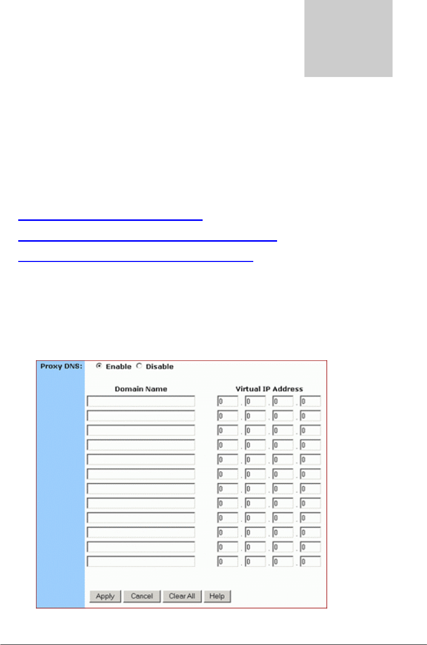
The Proxy DNS page appears, seen in FIGURE 4-13:
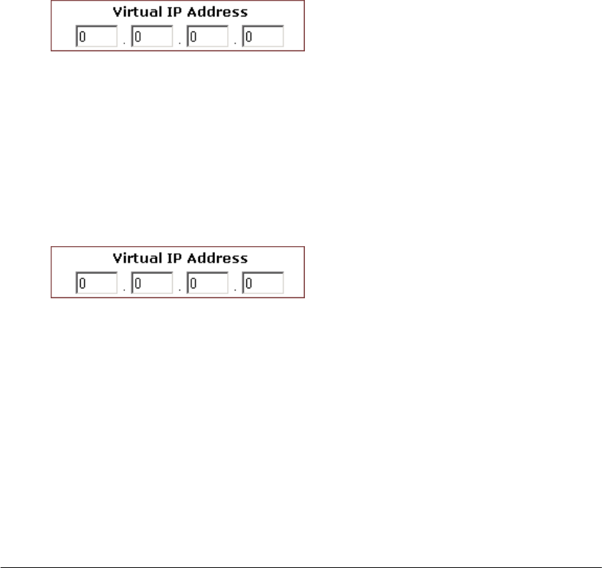
FIGURE 4-13: Proxy DNS Page
t
ADVANCED FUNCTIONS: PROXY DNS
Page 69 of 77
2. Select Enable next to Proxy DNS.
3. Type a name for one PC in your network that you want to use as a
Proxy DNS server in the Domain Name box.
4. Type the IP address for the PC in the Virtual IP Address box.
5. Optional. If you want to delete all the existing Proxy DNS servers first,
click Clear All and do Step 3 and Step 4.
6. When you have completed editing all the settings, click Apply, or click
Cancel to undo your changes.
To Delete a Specific or All Proxy DNS Servers:
1. On the Proxy DNS page, for any Proxy DNS server you want to delete,
type 0.0.0.0 in the Virtual IP Address box.
2. If you want to delete all the existing Proxy DNS servers, click Clear All.
3. Click Apply.
To Disable the Proxy DNS on Your Router:
1. On the Proxy DNS page, for any Proxy DNS server you want to delete,
type 0.0.0.0 in the Virtual IP Address box.
2. If you want to delete all the existing Proxy DNS servers, click Clear All.
3. Click Apply.

ADVANCED FUNCTIONS: SNMP
Page 70 of 77
SNMP
The Simple Network Management Protocol (SNMP) is an application layer
protocol that facilities the exchange of management information between
network devices. It is part of TCP/IP (Transmission Control
protocol/Internet Protocol) suite and enables you to control and monitor the
network in a simple way.
On the SNMP page, you can edit the basic Agent information and also
configure up to 6 SNMP trap receiver’s IP Addresses. When a trap
condition occurs, your router will send an SNMP trap message to any NMS
(Network Management System) specified as trap receivers, for example,
when power supply errors occur.
Notes
▪ NMS (Network Management System) is an SNMP management
application together with the computer it runs on.
▪ Currently the Company AP Router supports SNMPv1
(SNMP version 1) and SNMPv2 (SNMP version 2) which
have a number of features in common except for some
enhancements.
And moreover, you can specify different community names for
authenticating access to the management information, which function as
embedded passwords:
▪ Read: Gives you READ access to all the management
information, but does not allow WRITE access.
▪ Write: Gives you both READ and WRITE access to all the
management information.
Note – The community name definitions on your NMS must
match at least one of the above two community name
definitions.
What do you want to do?
▪ Configure Agent Information, SNMP Trap Host IP Addresses
and Community Names on Your Router
ADVANCED FUNCTIONS: SNMP
Page 71 of 77
▪ Delete an Existing SNMP Trap Receiver
▪ Delete SNMP Community Names
To Configure Agent Information, SNMP Trap Host IP Addresses and Community
Names on Your Router:
1. On the Advanced navigation bar, click SNMP.
The SNMP page appears, seen in FIGURE 4-14:
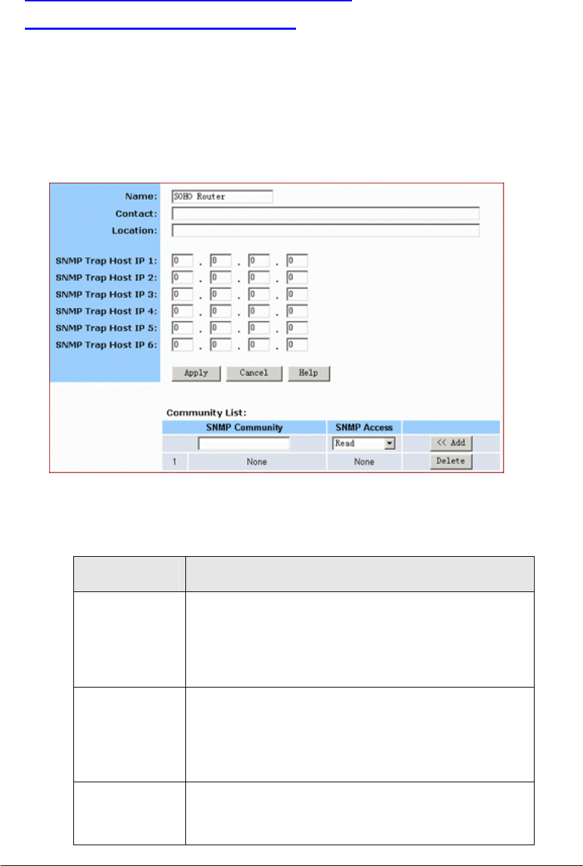
FIGURE 4-14: SNMP Page
2. Enter the following Agent information:
Parameter Description
Name Specifies an administratively-assigned name for
this managed node, like SOHO Router.
It is a string of the maximum 31 alphanumeric
characters.
Contact Specifies the contact person of this managed node,
plus phone number, Email address, etc.
It is a string of the maximum of 255 alphanumeric
characters.
Location Specifies the physical location of this managed
node, for example, city, address and specific office
location.
ADVANCED FUNCTIONS: SNMP
Page 72 of 77
It is a string of the maximum of 255 alphanumeric
characters.
3. To send SNMP trap messages to any NMS, type up to 6 trap receiver’
IP addresses in the SNMP Trap Host IP Address 1 – SNMP Trap Host IP
Address 6 boxes.
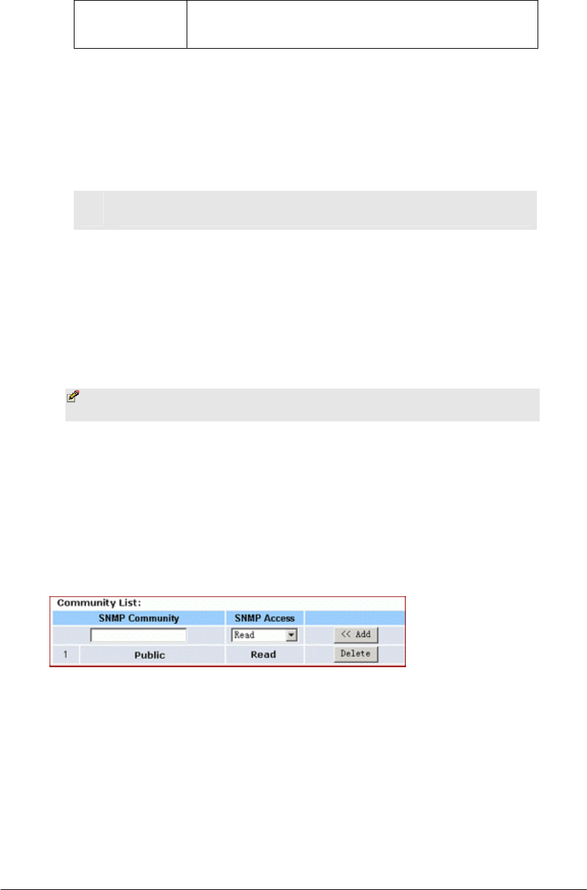
4. To secure SNMP with community names, do the following:
No. Action
1 Type a string in the SNMP Community box, like Public.
2 Select an option from the SNMP Access drop-down list, for
example, Read.
3 Click Add. If you want to add more community names, do
Step 4.1 – Step 4.3 again.
Note – Usually, we define a string of “Public” for Read
access and “Private” for Read-Write access.
5. When you have completed editing all the settings, click Apply, or click
Cancel to undo your changes.
To Delete an Existing SNMP Trap Receiver:
1. On the SNMP page, for any SNMP trap receiver that you want to
delete, enter 0.0.0.0 in the SNMP Trap Host IP Address box.
2. Click Apply.
To Delete SNMP Community Names:
1. On the SNMP page, for any SNMP community name that you want to
delete, click Delete in the corresponding row.
2. Click Apply.

ADVANCED FUNCTIONS: STATIC ROUTING
Page 73 of 77
Static Routing
The Static Routing is used to configure static routes to remote networks
manually, where the route is predefined and is not supervised by the Routing
Information Protocol (RIP). It can explicitly reduce the network traffic and
speed the Internet connects for a small network.
However, it may fall into a certain disadvantage. When a static router
involves more than one Hop, if the connection to the next hop goes down, the
router cannot be aware of the invalid path and continues to route traffic on
this hop.
On the Static Routing page, you can add up to 20 static routes by indicating:
▪ Destination LAN IP address and Subnet Mask
▪ Remote gateway
▪ Hop
▪ Router interface through which to forward the packets to the
destination.
Note – If the network topology changes, you may have to
make changes to the static routing tables for relevant static
routes.
What do you want to do?
▪ Add a New Static Route
▪ Delete a Static Route
To Add a New Static Route:
1. On the Advanced navigation bar, click Routing.
The Static Routing page appears, seen in FIGURE 4-15:
|

ADVANCED FUNCTIONS: STATIC ROUTING
Page 74 of 77
FIGURE 4-15: Static Routing Page
2. Enter the following static route information:
Parameter Description
Destination
LAN IP
Specifies the network address of the remote LAN
segment. For standard class "C" LANs, the network
address is the first 3 fields of this Destination LAN
IP, the 4th field can be left at 0.
Subnet Mask Specifies the Subnet Mask used on the remote LAN
segment. For class "C" networks, the standard
Network Mask is 255.255.255.0.
Gateway Specifies the IP Address of the router on the local
LAN segment to which this device is attached.
Note that it is NOT the router on the remote LAN
segment.
Hop Specifies the number of routers that must be
traversed to reach the remote LAN segment. Valid
values are 1 to 16.
Interface Specifies the interface through which the router
goes to the next hop or a particular network.
Available options are WAN, LAN and DMZ.
3. Click <<Add.
The new static route appears in the static routing list.
To Delete a Static Route:
1. On the Static Routing page, for any static route that you want to
delete, review the relevant information, seen in FIGURE 4 – 15.
3. Click Delete.

ADVANCED FUNCTIONS: STATIC ROUTING
Page 75 of 77
Federal Communication Commission Interference Statement
1 FEDERAL COMMUNICATIONS COMMISSION (FCC) REQUIREMENTS, PART 15
This equipment has been tested and found to comply with the
limits for a class B digital device, pursuant to part 15 of the FCC
Rules. These limits are designed to provide reasonable
protection against harmful interference in a residential
installation.
This equipment generates, uses and can radiate radio
frequency energy and, if not installed and used in accordance
with the instructions, may cause harmful interference to radio
communications. However, there is no guarantee that
interference will not occur in a particular installation. If this
equipment does cause harmful interference to radio or
television reception, which can be determined by turning the
equipment off and on, the user is encouraged to try to correct
the interference by one or more of the following measures:
1. Reorient or relocate the receiving antenna.
2. Increase the separation between the equipment and receiver.
3. Connect the equipment into an outlet on a circuit different
from that to which the receiver is connected.
4. Consult the dealer or an experienced radio/TV technician for
help.
This device complies with Part 15 of the FCC Rules. Operation
is subject to the following two conditions:
(1) This device may not cause harmful interference.
(2) This device must accept any interference received, including
interference that may cause undesired operation.
FCC Caution:
FCC RF Exposure Statement:
This equipment complies with FCC RF radiation exposure limits
set forth for an uncontrolled environment. This device and its

ADVANCED FUNCTIONS: STATIC ROUTING
Page 76 of 77
antenna must not be co-located or operating in conjunction
with any other antenna or transmitter.
In order to maintain compliance with the FCC RF exposure
guidelines, this equipment should be installed and operated
with minimum distance 20cm between the radiator and your
body. Use only with supplied antenna. Unauthorized antenna,
modification, or attachments could damage the transmitter and
may violate FCC regulations.
2 REGULATORY INFORMATION / DISCLAIMERS
Installation and use of this Wireless LAN device must be in
strict accordance with the instructions included in the user
documentation provided with the product. Any changes or
modifications (including the antennas) made to this device that
are not expressly approved by the manufacturer may void the
user’s authority to operate the equipment. The manufacturer is
not responsible for any radio or television interference caused
by unauthorized modification of this device, or the substitution
of the connecting cables and equipment other than
manufacturer specified. It is the responsibility of the user to
correct any interference caused by such unauthorized
modification, substitution or attachment. Manufacturer and its
authorized resellers or distributors will assume no liability for
any damage or violation of government regulations arising from
failing to comply with these guidelines.
CE Warning:
Regulatory statement ( R&TTE / WLAN IEEE 802.11 b/g )
European Standards dictate maximum radiated transmit power
of 100mW EIRP and frequency range 2.400-2.4835GHz; In
France, the equipment must be restricted to the
2.4465-2,4835GHzfrequency range and must be restricted to
indoor use.
CE Declaration of Conformity:

ADVANCED FUNCTIONS: STATIC ROUTING
Page 77 of 77
For the following equipment: Wireless LAN Card Bus
Is herewith confirmed to comply with the requirements set out
in the Council Directive on the Approximation of the Laws of
the Member States relating to Electromagnetic Compatibility
(89/336/EEC),
Is herewith confirmed to comply with the requirements set out
in the Council Directive on the Approximation of the Laws of
the Member States relating to Electromagnetic Compatibility
(89/336/EEC), Low-voltage Directive (73/23/EEC) and the
Amendment Directive (93/68/EEC), the procedures given in
European Council Directive 99/5/EC and 89/3360EEC. The
equipment was passed. The test was performed according to
the following European standards:
EN 300 328-2 V1.2.1 (2001-08)
EN 301 489-1 V.1.4.1 (2002-04) / EN 301 489-17 V.1.2.1 (2002-
04)
EN 50371: 2002
EN 60950: 2000