XIAMEN LEELEN TECHNOLOGY JB305S18 JB-305 color door station No.18A_IC User Manual
XIAMEN LEELEN TECHNOLOGY CO., LTD JB-305 color door station No.18A_IC Users Manual
Users Manual

Please read this manual carefully before the products are installed.
Technical specifications and contents are subject to change
accordingly without advance notification.
No:RP.000.ZC-SM.229
User’s Manual(V1.3)
J B - 3 0 5
Villa Video Door Entry System
1
CONTENTS
Part 1. Product introduction
1.1 Use purpose
1.2 System configuration
1.3 Features and functions
Page
1
1
2
1~2
Part 2. Technical parameters & structure
2.1 Technical parameters
2.2 Structure
3~5
Part 3. Installation and connection
3.1 Installation
3.2 Connection
Part 4. System programming
4.1 Audio jumper
4.2 Video jumper
4.3 Door station address
4.4 Card reader
4.5 Password (for Model No.18 only)
Part 5. Operation
5.1 Operation on door stations
5.2 Operation on indoor phone
Part 6. Troubleshooting
6.1 Test
6.2 Troubleshooting
6
8
16
16
17
18
20
26
28
33
33
6~15
16~25
26~32
33
3
4
Part 1. Product introduction
1.1 Use purpose
The system is applied to single family houses, offices, shops,
warehouses, and other access control purpose.
1.2 System configuration
Model No.18
102 175 39(mm)
Model No.15A surface
mount. 79 148 45(mm)
Model No.15B surface mount,
card reader. 79 148 45(mm)
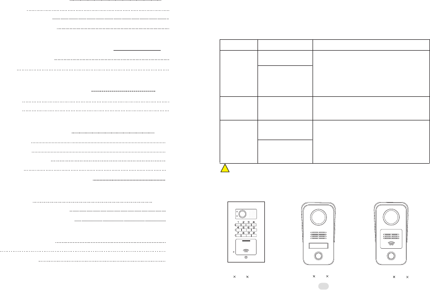
1.2.1 Door stations
CALL
MIC
Both are free voltage input AC100V~240V.
One transformer can support up to 4 indoor
phones while one adapter can support
only one indoor phone. But if there are 3
or more door stations, another transformer
may be required.
! We may provide more options and the current options may be replaced without
prior notification.
Configuration
Door station
Power supply
Adapter
(18VDC, 1A)
Transformer
(18VDC, 2.2A)
Options
Model No.15
Model No.18
Remarks
①
②
7" TFT color screen.
Every indoor phone requires the 18VDC
power.
①
②
All panels are aluminum.
Door stations don't require any direct power
③Card reader is available.
④Model No.18 is with a keypad for PIN
codes to release doors.
①
②
Indoor phone Model N60
supply.
(JB-305 color door station
No.18A_IC
JB-305MGCQ-S18AI)
(JB-305 indoor phone N60
JB-305VCW-70LN60)
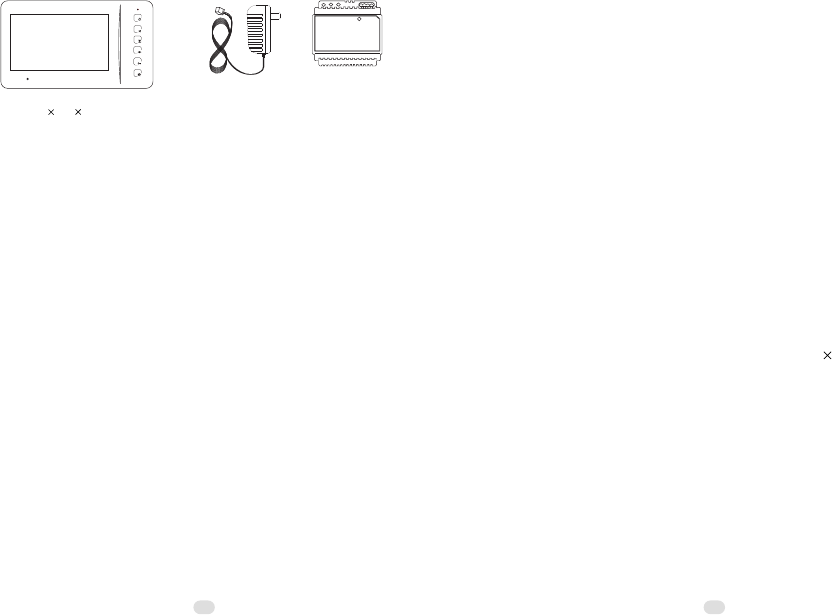
1.2.2 Indoor phone & Power supply
Indoor phone Model N60
239 139 20(mm)
Adapter Transformer
(DIN Rail)
(Power supply)
1.3 Features and functions
>Call, answer, and release doors.
>DIY system with 4 wires; PLUG & PLAY connection.
>Various flexible connection diagrams are optional.
>Max. capacity: Up to 4 door stations and 4 indoor phones.
>Intercom and calling transfer between indoor phones.
>12 melody ring tones are optional.
>Two options to release doors, by SIGNAL or by POWER.
>Use two group passwords to release two doors and gates
(Model No.18).
>Double unlock buttons to release two doors/gates/garages....
>Use cards to release the doors.
>Surface and flush mount are optional.
>Rainproof and anti-vandal.
>Night viewing; illuminated call button.
>Touch button indoor phones are optional.
>Privacy functions are available.
Part 2. Technical parameters & structure
2.1 Technical parameters
2.1.1 Door station
Camera:
Viewing angle:
Lens:
Resolution:
Min. illumination:
Video output:
Audio SNR:
Audio distortion:
Standby current:
Working current:
Working voltage:
Environment temperature:
1,300,000 Pixels, CMOS
92°
F=3.7
H: 350TVL V: 320TVL
0.01 LUX
1Vp-p/75Ω
≥25dB
≤7%
≤100mA
≤230mA
DC18V±10%
-40℃~+70℃
2.1.2 Indoor phone
Display:
Resolution:
Video output:
Audio SNR:
Audio distortion:
Standby current:
Working current:
Working voltage:
Environment temperature:
7"TFT, 800 480 Pixels
H: 350TVL V: 320TVL
1Vp-p/75Ω
≥25dB
≤7%
≤100mA
≤300mA
DC18V±10%
-25℃~+55℃
23
Intercom call button
45
2.1.3 Power supply
A) Model No.18 (Flush mount)
B)Model No.15 (Surface mount)
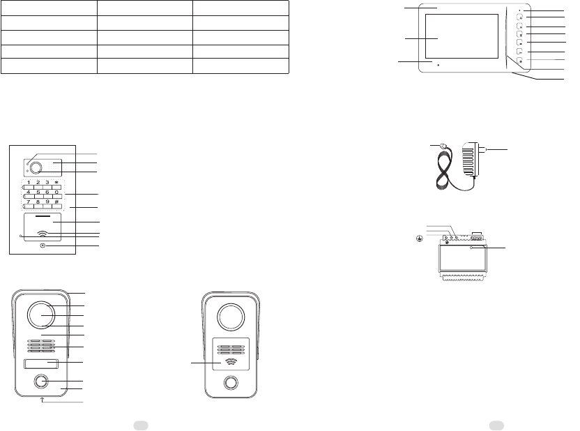
Rain shield(Surface mount bracket)
LEDs
Camera
Light sensor
Cast aluminium panel
Speaker
Name tag
Call button
Microphone
Screw
Card reader
inside
LEDs
Camera
Cast aluminium panel
Speaker
Call button
Microphone
Screw
Card reader inside
CALL
MIC
Keypad
Microphone
7" TFT-LCD screen
2.2.2 Indoor phone(Model N60)
ABS decorative coat
Function button1
Function button2
Monitor button
Unlock button
Answer button
Power indicator
Speaker
LED indicator
2.2.3 Power supply
A) Adaptor
B) Transformer
Power indicator
Anode(L)
Cathode(N)
Ground( )
Power output terminals
-+-+
N L
Input power plug
Output power plug
to indoor phone
Voltage input
Voltage output
Current output
Adapter
AC100V~240V
DC18V
1A
Optional
AC100V~240V
DC18V
2.2A
/
Transformer
Power plug style
2.2 Structure
2.2.1 Door stations

67
Part 3. Installation and connection
3.1 Installation
3.1.1 Door stations
A)Model No.18 (Flush mount)
a. Produce a groove(86.4x154.4x55mm) on a proper position of
the wall(①).
b. Take off the door panel from the box with the enclosed screw
driver(②③).
c. Fix the box in the groove with screws and expansion plugs or
cement(①).
d. Fix the door panel in the box with the screws(④).
B)Model No.15 (Surface mount)
a. Take off the door panel from the bracket with the enclosed
screw driver(①).
b. Fix the bracket on the wall with two screws and expansion
plugs(②).
c. Put the door panel on the bracket and fix it after connect the
cable(③).
Mind the actual camera viewing angle and put the door station on a proper position.
[the manufacturer suggests 1.4~1.8m of height.]
②Do not put the devices at the places where there are high voltage, high temperature,
strong magnet, corrosive, humidification, ets.
③Do not drag the cable.
④Keep the devices clean.
①
a.
Fix the bracket on the box or on the wall with the screws(① or
②).
b.
Move the indoor phone and put it on the bracket after connect
the cable(③).
3.1.2 Indoor phone
②④ ①
Door panel Box
③Wall
C A L L
MIC
expansion plugs
bracket
indoor phone
expansion plugs
③
②①
Hook
box
①
②
Bracket(rain shield)
Door panel ③
89
3.1.3 Name tag (Model No.15)
a. Press the name tag at a side and then take it off.
b. Change the name tag.
c. Insert the set of name tag into the groove and then press it to
be locked.
David Hunter David Hunter name tag
cover
spacer
3.2 Connection
3.2.1 Wires and distance
Wire diameter
≤50m
Best distance
≤100m
≥0.75mm2
≥1.5mm2≤100m
RVV2x1.0
(U.S.:AWG18)
mm2For DIN rail power supply
(transformer)
Remarks
Between the last door station
and the last indoor phone
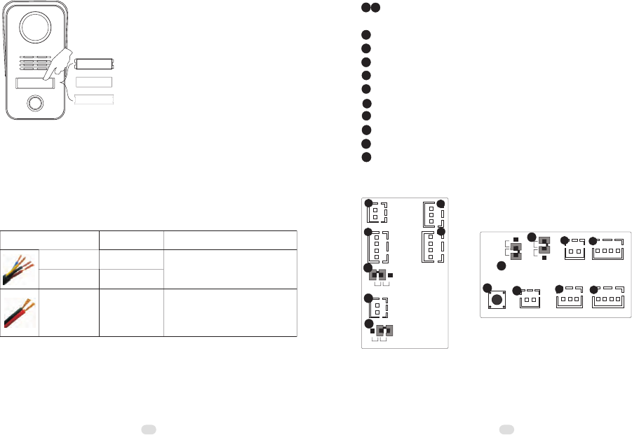
3.2.2 Terminals
6
7
Terminal for electronic SIGNAL lock
Terminal for exit button
Privacy jumper
SET button
3
4
5
Terminal for electronic POWER lock
Video jumper
8
9 Audio jumper
10
Terminal to power supply
11
Terminals for gates/garages/lights ...
12 Potentiometer for speech volume
1 2 Terminals to door station or/and indoor phone. Both have no
difference.
Model No.15
18V
AUDIO
VIDEO
GND
A) Door stations
Model No.18
1
2
4
L- L+
7
NC
ND
VM
1
3
6
6
8
COM NC NO
5
COM
NC
NO
GO OUT
+18V
AUDIO
VIDEO
GND
NC
NC
ND
3
4
2
VM
NC
GO OUT
5
L-
L+
8
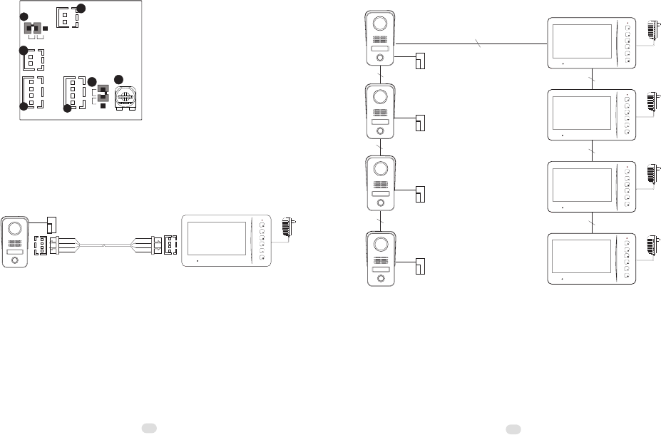
3.2.3 Component diagram
A. Basic connection
e-lock
B. Best connection for up to 4 door
stations and 4 indoor phones
RVV4x0.75mm2
RVV4x0.75mm2
RVV4x0.75mm2
RVV4x0.75mm2
RVV4x0.75mm2
RVV4x0.75mm2
RVV4x0.75mm2
e-lock
e-lock
e-lock
e-lock
B) Indoor phone
+18V
Model N60
GND
10
11
PWR
AU
9
2
VD
GND
AF
NC
1VM
8
NC
12
11
10
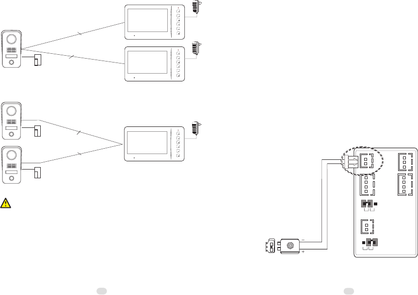
C2. Example 2:
e-lock
2
RVV4x0.75mm
2
RVV4x0.75mm
e-lock
2
RVV4x0.75mm
C. Other workable connection
C1. Example 1:
12 13
e-lock
2
RVV4x0.75mm
①The basic components are 1 door station, 1 indoor phone, and 1 power supply.
The max. capacity the manufacturer suggests is 4 door stations and 4 indoor phones.
More components may cause malfunctions.
②One adapter can support only one indoor phone while one transformer can only
one indoor phone while one transformer can support up to 4 indoor phones. But if
there are 3 or 4 door stations, one more adapter or transformer is required, because
the turning monitor function may be not workable.
③All door stations do not require power supply.
④For easy connection the diagrams of C1 and C2 can be applicable to projects
accordingly.
⑤Video jumpers may be helpful in case there is any problem with image display
especially while 2 or more indoor phones are used. Please go to 4.2 for the jumpers'
usage.
⑥When there are 2 or more door stations, door stations have to be addressed so
that every door stations have their exclusive address codes. If there are, please go to
4.3 for door station address.
⑦In case more indoor phones or door stations are required in diagram A, C1 and
C2, please connect them from the terminal wires and try. If the image quality is not
good enough and the image adjustors cannot help, please read 4.2 and try
accordingly.
3.2.4 Electronic locks
There are various electronic locks. People from different
countries may have different practice of using electronic locks.
Generally speaking there are two methods to release doors via
door entry systems. One is SIGNAL. Another is POWER. This
system supports both. Users may adopt either accordingly.
A) Diagrams for POWER electronic locks
(example: Door station Mode l No. 15)
18V
AUDIO
VIDEO
GND
NC
ND
COM
NC
NO
VM
NC
GO OUT
L-
L+
14
B) Diagrams for SIGNAL electronic locks
(example: Door station Model No. 15)
12VDC
18V
AUDIO
VIDEO
GND
NC
ND
COM
NC
NO
VM
NC
GO OUT
L-
L+
①Please choose one of the above mentioned diagrams according to the
②
⑥
⑦
Instant output (Diagram A): 12VDC, 500mA.
In diagram B, COM terminal has to be connected. NC means close circuit.
④
⑤
③
electronic locks.
NO means open circuit. Please choose a right terminal according to the
electronic locks.
The electronic locks can keep releasing in 5 seconds.
SIGNAL locks and POWER locks can be connected to different door stations.
There is no interference.
A SIGNAL lock and a POWER lock can be connected to the same door station.
Please mind if the wires of electronic locks are nonpolarity.
15
e-lock
or
Gates, garages, lights, or etc.
...
Caution!
Max. contact load(terminals in 3.2.2): 2A/30VDC and 0.5A/125VAC.
DO NOT exceed the parameters. Otherwise it may cause damages.
11
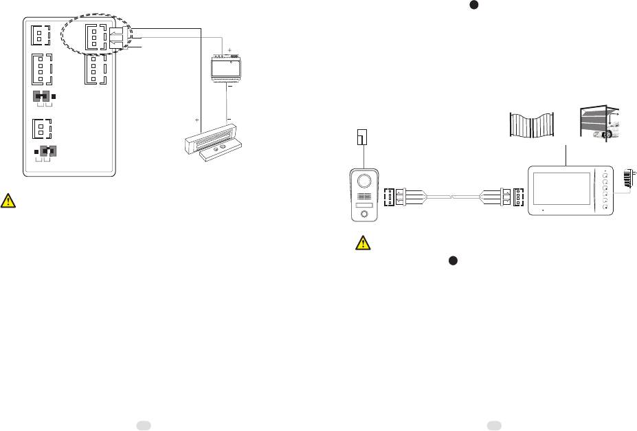
3.2.5 Terminals for gates/garages/lights ...
There are the terminals with relays on the back of the
indoor phones. They can be applicable for gates garages,
lights, etc. The relays can keep releasing in 1.5 seconds.
11
16 17
Part 4. System programming
4.1 Audio jumper
The audio jumper has to be put on AF position in the indoor
phone if there is only one indoor phone. In case there are more
indoor phones, only the first indoor phone is required to do that.
Meanwhile the other indoor phones' jumpers have to be put on
NC position. Please do the same if there are two or more routes
such as the diagrams of C1 and C2 in 3.2.3.
+18V
GND
10
11
PWR
AU
9
2
VD
GND
AF
NC
1VM
8
NC
12
indoor phone(Model N60)
4.2 Video jumper
In case the image display is rolling or with any other
abnormality problem and the image adjustors can not help, the
video jumpers have to be put on video matching position in the
last indoor phone and the last door station in diagram A and B,
the two indoor phones in diagram C1 and the two door stations
in diagram C2. Meanwhile the other devices' jumpers have to be
put on NC position.
+18V
GND
10
11
PWR
AU
9
2
VD
GND
AF
NC
1VM
8
NC
12
indoor phone (Model N60)
Door station (Model No.18)
1
2
4
L- L+
7
VM
6
8
COM NC NO
5
GO OUT
+18V
AUDIO
VIDEO
GND
NC
NC
ND
3
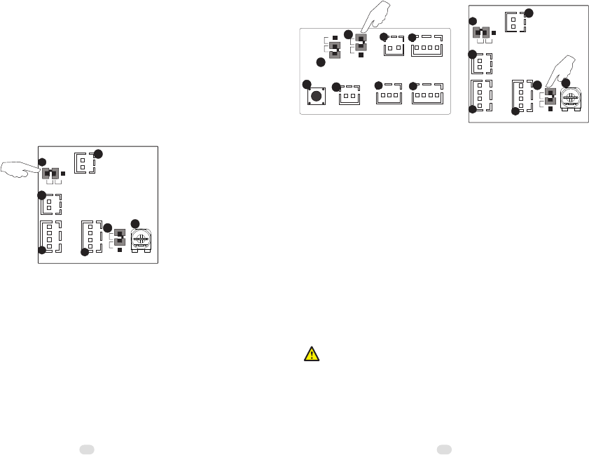
4.3 Door station address
If there are two or more door stations, door stations have to
be addressed. Maximum capacity is 4 door stations.
There is a SET button on the back of the door stations.
Keep pushing the SET button until it sounds double beeps.
Then the door station is ready for setting. Continue to push the
SET button again and again. The door station will sound
continuous double beeps, triple beeps, and quadruple beeps by
turns. The door stations are all No.1 by default. Double beeps
is for No.2. Triple beeps is for No.3. Quadruple beeps is for
No.4. Please choose the options and keep pushing the SET
button to set the address number accordingly.
Please be sure every door station has exclusive address numbers if they work
together.
18 19
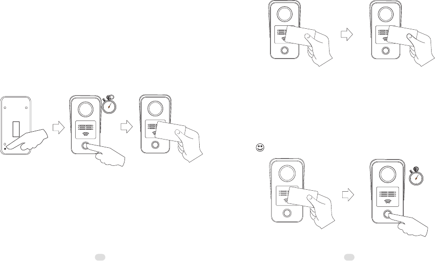
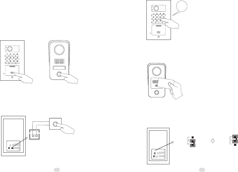
4.4 Card reader
A. Register master cards
The system provides up to 8 master cards. Users may use the
card to register or cancel other cards easily.
a.
Push the SET button on the back of the door station (①).
b.
Push the CALL button and do not release it for 2 seconds(②).
The door station will sound double beeps. At this moment the
system gets ready to register master cards.
c.Put a card proximate to the reader(③). When the door station
sounds a beep, the card is registered as a master card
successfully. If more master cards are needed, please
continuously put more cards proximate to the reader one by
one.
d.
Exit by pushing the SET button again(①). (It also can exit
automatically after 15 seconds.)
2"
MA ST ER
B. Register user cards
a. Put a master card proximate to the reader(①). The reader will
get ready to register user cards as soon as the door station
sounds a long beep.
b. Put a card proximate to the reader(② ). The door station will
sound a beep if it is registered as a user card successfully.
If more user cards are needed, please continuously put more cards proximate to
the reader one by one
. (
Max. capacity: 120pcs)
Exit by putting the master card proximate to the reader again
(①). (It also can exit automatically after 15 seconds.)
c.
MA ST ER
C. Cancel cards
a. Put a master card proximate to the reader(①). The door
station will sound a long beep.
b. Push the CALL button and do not release it for 2 seconds(②).
All registered user and master cards will be canceled as soon
as the door station sounds a long beep again.
Meanwhile the reader gets ready for registering master cards.
MA ST ER
2"
4.5 Password settings (for Model No.18 only)
Residents are allowed to use passwords to release the doors
on the door station Model No.18. There are three group
passwords. They are
> System password (default:1234). It is the key to change all
passwords.
> Entry password 1 (default:1235). It is the key to open the
doors that connect to the terminals of the door stations.
> Entry password 2 (default:1236). It is the key to open the
gates that connect to the terminals of the indoor phones.
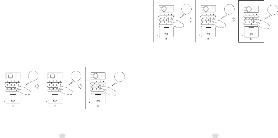
4.5.1 Change passwords
A) Change the system password
Step 1> Push *00*. If it sounds a long beep, then
Step 2> Push the old password and end by * button. If it sounds
a long beep, then
Step 3> Push the new password and end by # button. If it sounds
a long beep, the new password is valid. For example, if the
default password needs to be changed to 4444, then do as the
following figures.
20 21
C A L L
MIC
*00*
C A L L
MIC
1234*
C A L L
MIC
4444#
Change entry password1
B)
Step 1> Push *01*. If it sounds a long beep, then
Step 2> Push the old password and end by * button. If it sounds
a long beep, then
Step 3> Push the new password and end by # button. If it sounds
a long beep, the new password is valid. For example, the default
password needs to be changed to 5555, then do as the following
figures.
C A L L
MIC
*01*
C A L L
MIC
1235*
C A L L
MIC
5555#
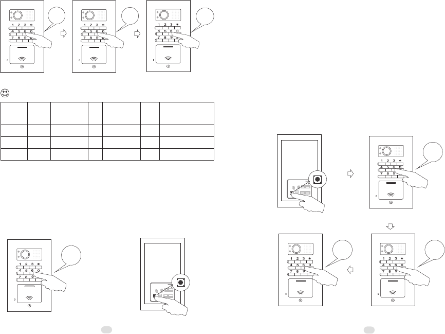
C) Change entry password 2
Step 1> Push *02*. If it sounds a long beep, then
Step 2> Push the old password and end by * button. If it sounds
a long beep, then
Step 3> Push the new password and end by # button. If it sounds
a long beep, the new password is valid. For example, if the
default password needs to be changed to 6666, then do as the
following figures.
step 1 step 2 step 3
step 1 step 2 step 3
C A L L
MIC
*02*
C A L L
MIC
1236*
C A L L
MIC
6666#
step 1 step 2
The three group passwords should be exclusive to each other.
4.5.2 Get into the program status
Method 1>> Use the system password on the door station.
For example, push 1234 as the following figure.
Method 2>>Push the SET button on the back of the door
station as the following figure.
The door station will sound a beep to indicate the successful operation. Otherwise it
will sound double beeps instead. It is same to 4.5.3.
OR
C A L L
MIC
1234
VM
VM
NC
L+ L-
ND
NC
4.5.3 Reset password
In case residents forget the passwords, please follow the steps
to reset the passwords.
A)
Reset the system password
Step 1>Push the SET button on the back of the door station
to get into the program status.
Step 2>Push *00*. If it sounds a long beep, then
Step 3>Push the new password and end by * button. If it
sounds a long beep, then
Step 4>Repeat the new password and end by # button. If
it sounds a long beep, the new password is valid. For
example, if the forgotten password needs to be reset to 4444,
then do as the following figures.
C A L L
MIC
*00*
VM
VM
NC
L+ L-
ND
NC
C A L L
MIC
4444#
C A L L
MIC
4444*
2223
step 3
step 1 step 2
step 3
step 4
A
B
C
Remarks
Group
*00*
*01*
*02*
1234
1235
1236
Start
*
*
*
New
password
#
#
#
End
Standby status
Standby status
Standby status
Current
password
4444
5555
6666
2425
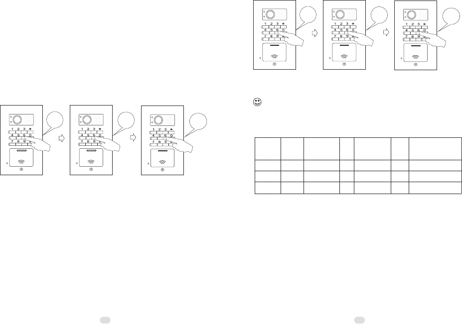
B) Reset entry password 1
Step 1> Push the SET button on the back of the door station to
get into the program status.
Step 2> Push *01*. If it sounds a long beep, then
Step 3> Push the new password and end by * button. If it sounds
a long beep, then
Step 4>Repeat the new password and end by # button. If it
sounds a long beep, the new password is valid. For example, if
the forgotten password needs to be reset to 5555, then do as the
following figures.
C A L L
MIC
*01*
C A L L
MIC
5555*
C A L L
MIC
5555#
C) Reset entry password 2
Step 1> Push the SET button on the back of the door station to
get into the program status.
Step 2> Push *02*. If it sounds a long beep, then
Step 3> Push the new password and end by * button. If it sounds
a long beep, then
Step 4>Repeat the new password and end by # button. If it
sounds a long beep, the new password is valid. For example, if
the forgotten password needs to be reset to 6666, then do as the
following figures.
C A L L
MIC
*02*
C A L L
MIC
6666*
C A L L
MIC
6666#
Before the door station exits the program status, the change can be tried again
by repeating step 2 - 4 once the previous operation fails. ②The three group passwords
should be exclusive to each other. ③The three group passwords can be set one by one
at one time by starting from step 2, while the door station is on the program status.
①
4.5.4 Exit the program status
Method 1> Push # button.
Method 2> Push the SET button.
Method 3> Don’t operate in 15 seconds.
step 2 step 3 step 4
step 2 step 3 step 4
A
B
C
Remarks
Group
*00*
*01*
*02*
4444
5555
6666
Start
*
*
*
New
password
#
#
#
End
New
password
4444
5555
6666 Setting status
Setting status
Setting status
26 27
Part 5. Operation
5.1 Operation on door stations
5.1.1 Call residents
Push the CALL button on the door station. The door will sound
a feedback ring if the calling is successful and the red LED
indicators on indoor phones will turn on. The calling can be
ended immediately once the call button is pushed again.
C A L L
MIC
5.1.4 Use cards to release doors
Put a registered card proximate to the reader. The door
station will sound a beep.
5.1.3 Use passwords to release doors
Push 4 digits password (e.g. 5555).
C A L L
MIC
5555
5.1.2 Push the exit button to release doors
There is the terminal for exit button on the back of the door
station. Push the exit button, the door station will sound a beep
and release the door.
VM
VM
NC
L+ L-
ND
NC
GO OUT
DOOR
EXIT
GO OUT
5.1.5 Privacy setting on door stations
Put the privacy jumper on "NC" position. The door station
will enter the privacy status, then it will not sound a feedback
ring when it calls the indoor phones.
VM
VM
NC
L+ L-
GO OUT
NC
ND
ND
NC
ND
NC
Privacy OFF Privacy ON
28 29
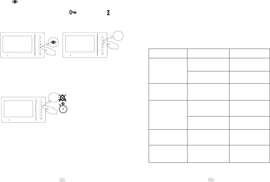
5.2.3 Release gates/garages ...
Push button if the indoor phones are with the function.
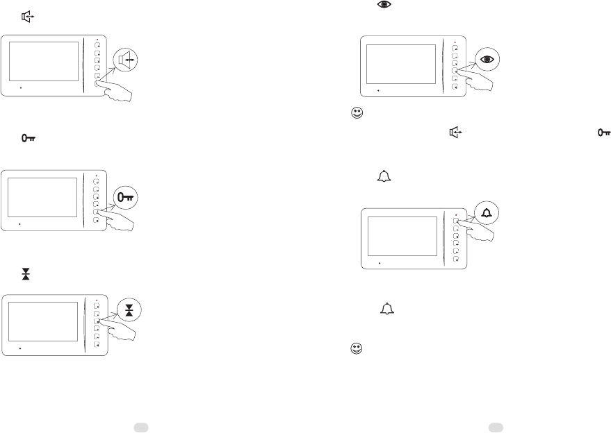
5.2 Operation on indoor phone
5.2.1 Answer
Push button and speak.
5.2.2 Release door
Push button while the indoor phone is at intercom status or
surveillance.
5.2.6 Call transfer
Push button to ring the other indoor phones while at
intercom status. If somebody answers, the line will be
transferred.
Functions of 5.2.5 and 5.2.6 are available only if there are two or more indoor
phones.
If there are two or more cameras, surveillance for different entrances is also
available by a 2nd, 3rd, or 4th push. During surveillance it is available to speak with
somebody outside by pushing button and release the door by pushing button.
5.2.4 Video surveillance
Push button and then the image in front of the camera will
be displayed on the screen.
5.2.5 Call other indoor phones
Push button to ring the other indoor phones while at the
standby status, the green LED indicators will turn on.
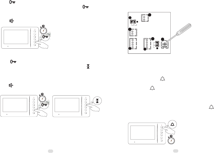
5.2.7 Change the ring tone
2"
Push button and do not release it for 2 seconds. The indoor
phone will ring. At this moment users may push button
again and again to choose the favorite ring. The choice will be
accepted once the indoor phone shuts automatically or the users
push button.
5.2.8 Adjust the ring volume
Push button and do not release it for 2 seconds, then the
indoor phone rings. While adjusting users may push button
again and again to increase/decrease the ring volume. There are
8 levels. The levels will turn to next one by one. The setting
will quit itself if no operation in 10 seconds. Users also may
push button to confirm the setting and exit immediately.
2"
5.2.9 Adjust the speech volume
Adjust the potentiometer on the back of the indoor phone with a
tool such as a proper screw driver.
Model N60
GND
10
11
PWR
AU
9
VD
GND
AF
NC
1
NC
8VM 12
+18V
2
2"
5.2.10 Change the ring duration
The default ring duration is 15 seconds. There are 10 seconds,
15 seconds, 30 seconds and 45 seconds for options. At the
standby status push button and do not release it for 2
seconds. The indoor phone will sound a beep. At this moment
users may push button once to switch to the first option (10
seconds), then push the button again and again to switch to the
next option in turn. It will sound double beeps when it switches
to the last option (45 seconds). The setting will be accepted and
synchronized to the other indoor phones by pushing button
for 2 seconds or quit automatically if no operation in 10
seconds.
30 31
33
5.2.12 Privacy setting
At the standby status push M button and do not release it for 2
seconds. The indoor phone will enter or exit privacy status with
a beep. During privacy, the red LED indicator keeps flashing.
2"
5.2.11 Operation on OSD menu
Push button to activate the screen. Then push M button to
activate the OSD menu. There are the items of brightness,
contrast and color. Users may push button (+) and button
(-) to adjust the parameters, and push M button to confirm or
skip them.
M
M
Part 6. Troubleshooting
6.1 Test
After all components are installed and connected as the user's
manual, please switch the power on and then try to operate all
features on all door stations and indoor phones as Part 5.
6.2 Troubleshooting
Common malfunctions Possible reasons Obviation
No feedback ring after
pushing the call button.
Meanwhile the door
station's LED indicator
doesn't turn on.
Disconnection on the
power supply or socket.
No image displayed.
The others are all ok.
Disconnection on the
(black) signal wire of the
indoor phone.
Poor image quality or
ghost image
No video jumper connected
on the indoor phone or
door station.
Video jumper is not on the
right device.
Receive a call but cannot
answer.
Audio jumper is not on the
right position (usually AF).
Replace the power
supply or the socket.
Check and connect the
wires.
Check and connect the
wires.
Check and connect the
video jumper.
Use the video jumper on
the correct device.
Use the audio jumper
on the right position
accordingly.
Disconnection on the (red
or black) signal wires.
Unavailable to activate a
2nd camera.
The power is too weak to
support the whole system.
32
If use only one transformer,
please add another
transformer/adapter.
This device complies with Part 15 of the FCC Rules. Operation is
subject to the following two conditions:
(1)this device may not cause harmful interference, and
(2)this device must accept any interference received, including
interference that may cause undesired operation.
INFORMATION TO THE USER
This equipment has been tested and found to comply with the
limits for a Class B digital device, pursuant to Part 15 of the FCC
Rules. These limits are designed to provide reasonable protection
against harmful interference in a residential installation. This
equipment generates, uses and can radiate radio frequency energy
and, if not installed and used in accordance with the instructions,
may cause harmful interference to radio communications.
However, there is no guarantee that interference will not occur in
a particular installation. If this equipment does cause harmful
interference to radio or television reception, which can be
determined by turning the equipment off and on, the user is
encouraged to try to correct the interference by one or more of the
following measures:
-- Reorient or relocate the receiving antenna.
-- Increase the separation between the equipment and receiver.
-- Connect the equipment into an outlet on a circuit different from
that to which the receiver is connected.
-- Consult the dealer or an experienced radio/TV technician for
help.
CAUTION
changes or modifications not expressly approved by the party
responsible for compliance could void the user’s authority to
operate the equipment.