Xeline LTd EU-200BX EMS agent User Manual EU 200BX Manual eng V03 final
Xeline Co., LTd. EMS agent EU 200BX Manual eng V03 final
UserManual.wiki
>
Xeline LTd
>
EU 200BX User Manual
Users Manual
Navigation menu
Upload a User Manual
Namespaces
Wiki Guide
HTML
PDF
Info
Views
User Manual
Discussion / Help
Navigation

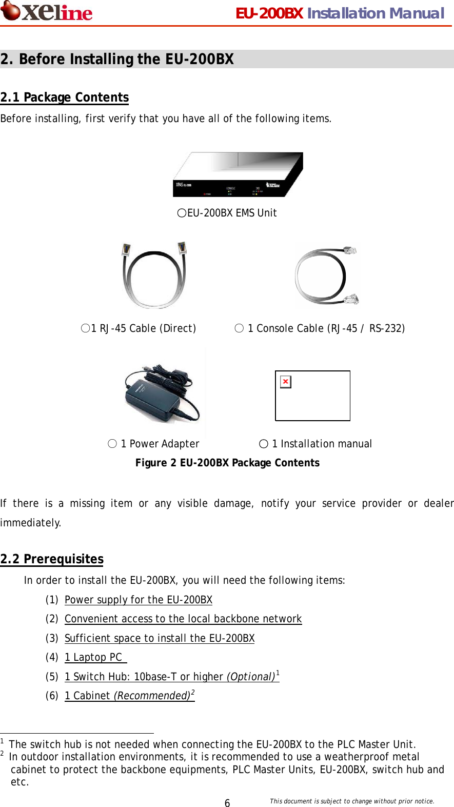
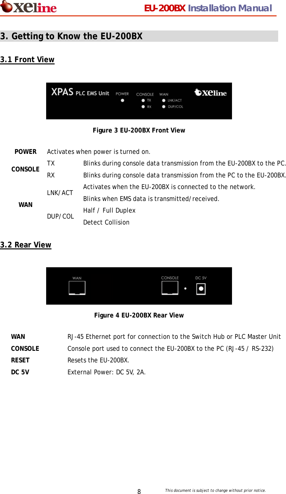
![EU-200BX Installation Manual This document is subject to change without prior notice. 93.3 Product Specifications (1) Hardware Specifications Category Specifications Main Processor KS8695X RAM 32MB SDRAM Flash Memory 2MB X1 NOR FLASH 32MB X1 NAND FLASH Serial Port RS232 [1 port] – Console 2 Serial Port – Data (Optional) Ethernet Link 10/100 Base Auto Negotiation Auto MDIX Power External Power : DC 5V, 2A Dimensions 190 x 110 x 31mm (W x D x H) Weight 664g (2) Software Specifications Category Specifications Operating Software Embedded Linux (Kernel Version 2.4.x) Supported Protocols RFC 791 IP RFC 793 TCP RFC 1157 SNMP v1 RFC 1213 MIB II RFC 1901 SNMP v2 Supported Functions Remote OS Upgrade Remote configuration PLC equipment control NMS using SNMP Supported Services Inetd, ftp, ssh, http, tftp, SNMP Supported Commands Busy box](https://usermanual.wiki/Xeline-LTd/EU-200BX/User-Guide-625572-Page-9.png)
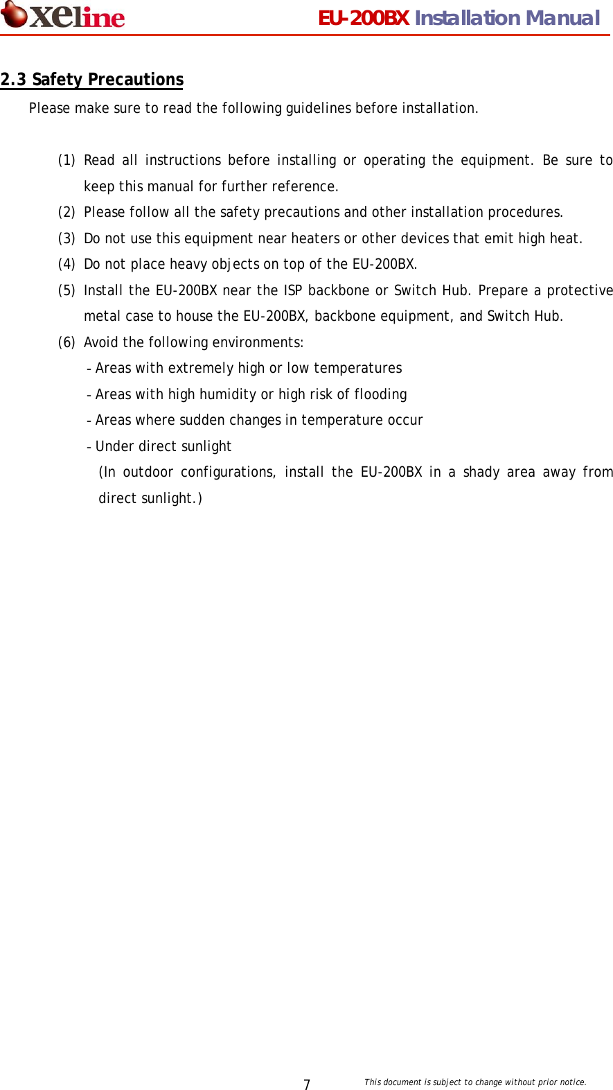
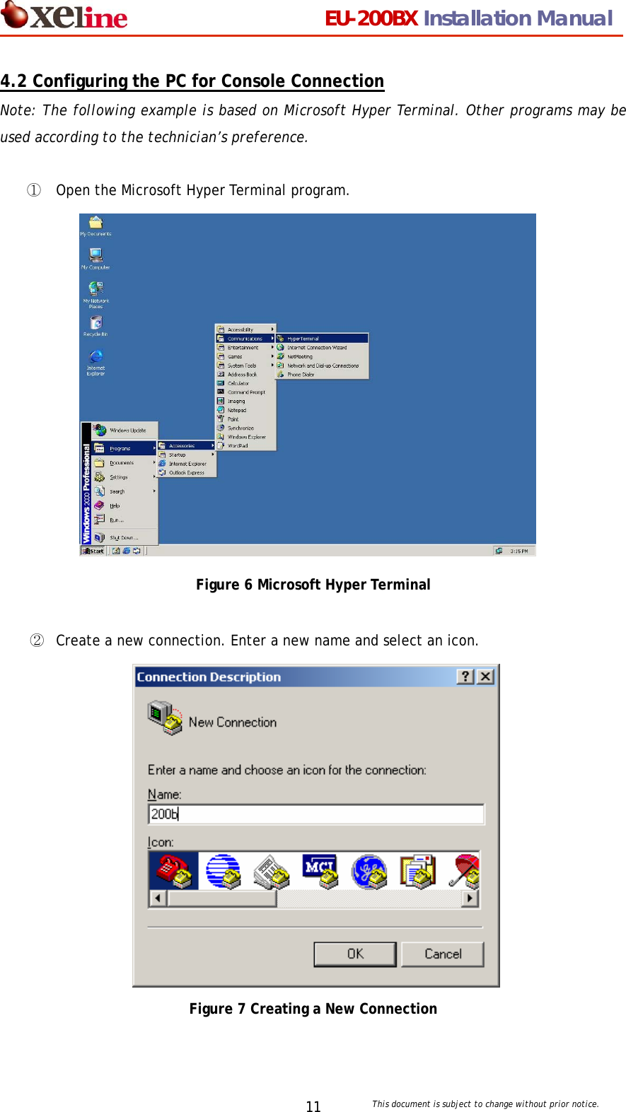
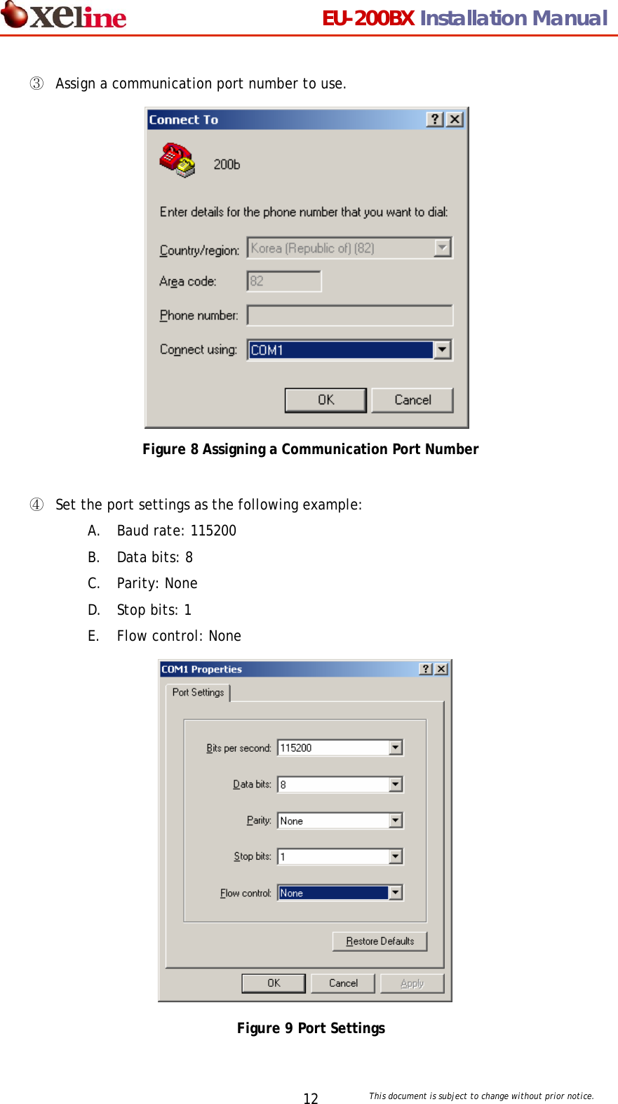
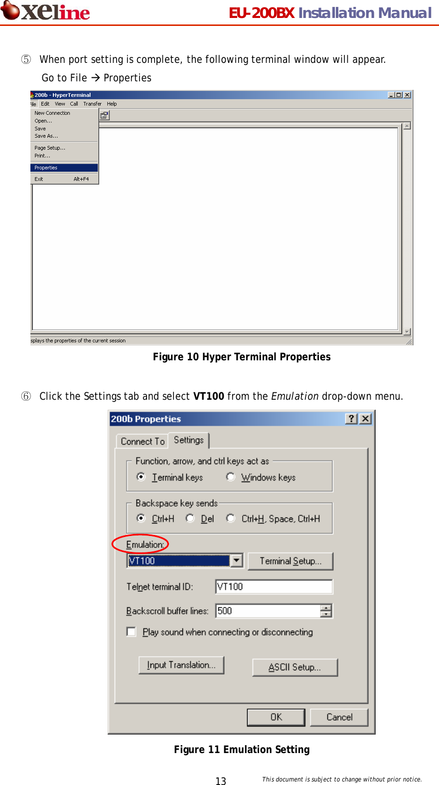
![EU-200BX Installation Manual This document is subject to change without prior notice. 104. Installing the EU-200BX 4.1 Connecting the LAN and Console Note: The EU-200BX should be located within the same broadcasting domain as the Stations to be managed. ① Connect the ISP backbone to the UPLINK port of the Switch Hub or PLC Master Unit. ② Insert a RJ-45 direct cable into the LAN port of the EU-200BX and connect to the LAN port of the Switch Hub. [Note] When connecting directly to the PLC Master Unit, insert the RJ-45 cable into an available RJ-45 port of the PLC Master Unit. ③ Insert the RJ-45 / RS-232 cable into the CONSOLE port of the EU-200BX. Connect the other end of the cable to the SERIAL port of the PC. ④ Connect the power adaptor to the EU-200BX and plug into the power outlet. Figure 5 Connecting the LAN and Console EU-200BXB](https://usermanual.wiki/Xeline-LTd/EU-200BX/User-Guide-625572-Page-10.png)
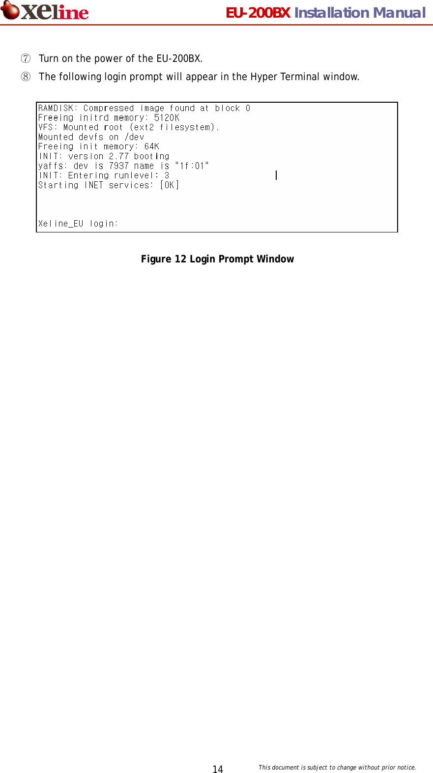
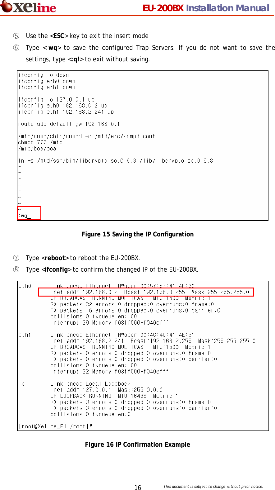
![EU-200BX Installation Manual This document is subject to change without prior notice. 154.3 Setting the IP of the EU-200BX ① Use the following id and password to log into the EU-200BX. Login ID: root Password: xeline (optional) Figure 13 EU-200BX Login ② Type <vi /mtd/etc/start>. ③ When the following screen appears, type<i> to change to the INSERT mode. ④ Modify the IP address in “ifconfig eth0” and “route add default gw”. [Important Note] Always use a fixed IP address. DHCP is not supported! Figure 14 IP Configuration Example [Note 1] To delete a typo in the IP address, you must FIRST EXIT the insert mode. This can be done by using the <ESC> key. Then point the cursor to the letter to delete and press the <x> key. One letter will be deleted at a time. To reenter the IP address, type <i> to return to the insert mode. [Note 2] If the cursor does not move using the direction keys, check if the emulation setting is set to VT100. If the emulation is NOT SET to VT100, the cursor may not move.](https://usermanual.wiki/Xeline-LTd/EU-200BX/User-Guide-625572-Page-15.png)
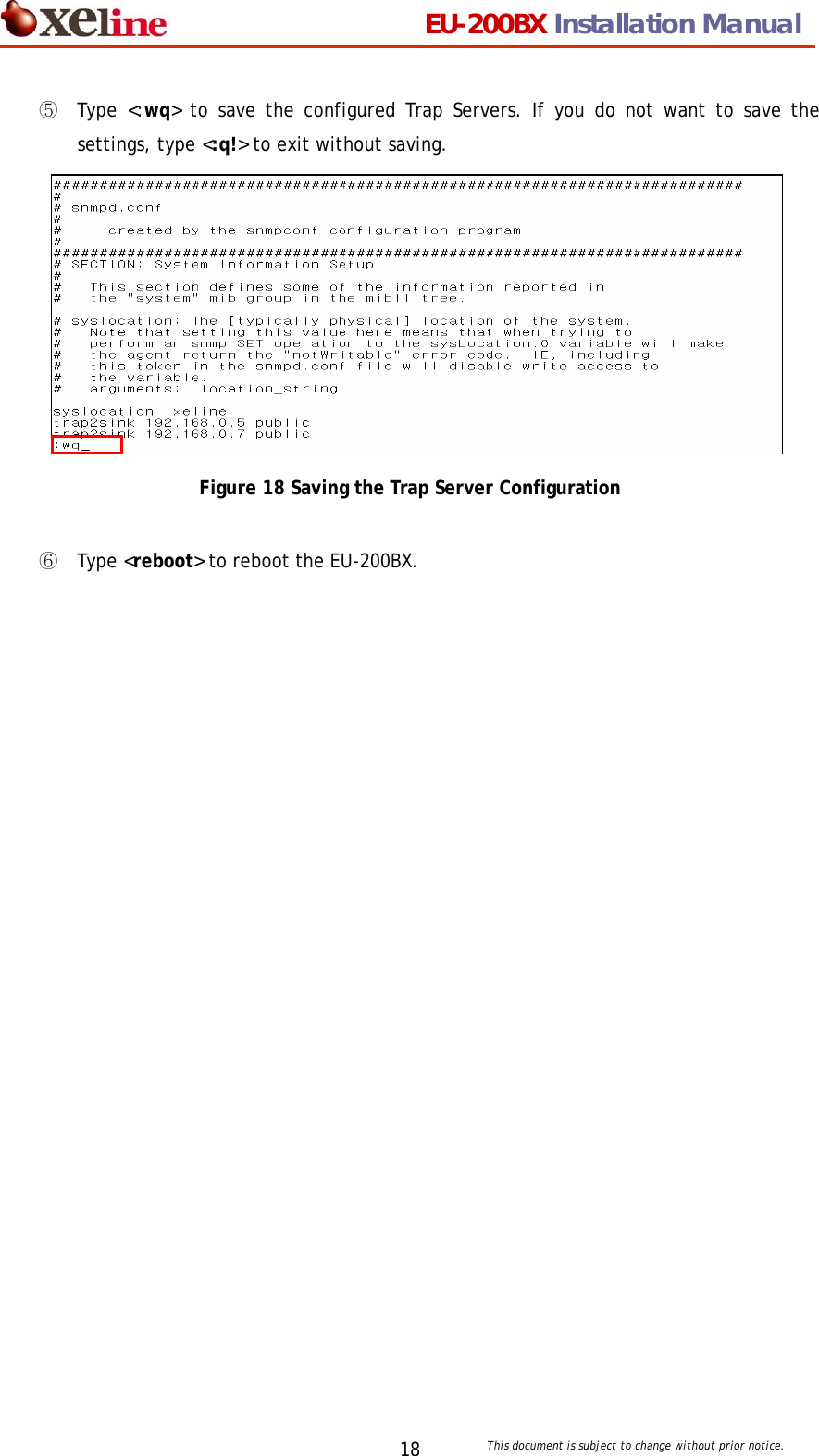
![EU-200BX Installation Manual This document is subject to change without prior notice. 174.4 Setting the Trap Server of the EU-200BX (Optional) ① Type <vi /mtd/etc/snmpd.conf> ② When the following screen appears, type<i> to change to the insert mode. ③ Type <trap2sink TRAP_SERVER_IP public>. The TRAP_SERVER_IP refers to the IP address of the EMS Server to where the trap messages will be sent. It is possible to designate multiple Trap Servers. Figure 17 Trap Server Configuration [Note 1] To delete a typo in the IP address, you must FIRST EXIT the insert mode. This can be done by using the <ESC> key. Then point the cursor to the letter to delete and press the <x> key. One letter will be deleted at a time. To reenter the IP address, type <i> to return to the insert mode. [Note 2] If the cursor does not move using the direction keys, check if the emulation setting is set to VT100. If the emulation is NOT SET to VT100, the cursor may not move. ④ Use the <ESC> key to exit the insert mode.](https://usermanual.wiki/Xeline-LTd/EU-200BX/User-Guide-625572-Page-17.png)