Xeline LTd EU-200BX EMS agent User Manual EU 200BX Manual eng V03 final
Xeline Co., LTd. EMS agent EU 200BX Manual eng V03 final
Users Manual

EU-200BX
Installation Manual
PLC EMS Unit
Plug into the future
Powerline Communication by Xeline
Xeline Co., Ltd.

EU-200BX Installation Manual
This document is subject to change without prior notice.
2
Table of Contents
1. Introduction······························································································· 5
2. Before Installing the EU-200BX········································································· 6
2.1 Package Contents ···················································································· 6
2.2 Prerequisites·························································································· 6
2.3 Safety Precautions ··················································································· 7
3. Getting to Know the EU-200BX········································································· 8
3.1 Front View····························································································· 8
3.2 Rear View······························································································ 8
3.3 Product Specifications··············································································· 9
4. Installing the EU-200BX·················································································10
4.1 Connecting the LAN and Console ·································································10
4.2 Configuring the PC for Console Connection·····················································11
4.3 Setting the IP of the EU-200BX····································································15
4.4 Setting the Trap Server of the EU-200BX (Optional)···········································17
5. Trouble Shooting·························································································19
6. Appendix··································································································20

EU-200BX Installation Manual
This document is subject to change without prior notice.
3
Figure Index
Figure 1 PLC EMS System Configuration....................................................... 5
Figure 2 EU-200BX Package Contents.......................................................... 6
Figure 3 EU-200BX Front View.................................................................. 8
Figure 4 EU-200BX Rear View................................................................... 8
Figure 5 Connecting the LAN and Console...................................................10
Figure 6 Microsoft Hyper Terminal............................................................11
Figure 7 Creating a New Connection .........................................................11
Figure 8 Assigning a Communication Port Number .........................................12
Figure 9 Port Settings ...........................................................................12
Figure 10 Hyper Terminal Properties .........................................................13
Figure 11 Emulation Setting ...................................................................13
Figure 12 Login Prompt Window...............................................................14
Figure 13 EU-200BX Login ......................................................................15
Figure 14 IP Configuration Example ..........................................................15
Figure 15 Saving the IP Configuration ........................................................16
Figure 16 IP Confirmation Example...........................................................16
Figure 17 Trap Server Configuration..........................................................17
Figure 18 Saving the Trap Server Configuration.............................................18

EU-200BX Installation Manual
This document is subject to change without prior notice.
4
ATTENTION
This equipment has been tested and found to comply with the limits for a Class B digital
device, pursuant to part 15 of the FCC Rules. These limits are designed to provide reasonable
protection against harmful interference in a residential installation. This equipment
generates, uses and can radiate radio frequency energy and, if not installed and used in
accordance with the instructions, may cause harmful interference to radio communications.
However, there is no guarantee that interference will not occur in a particular installation. If
this equipment does cause harmful interference to radio or television reception, which can be
determined by turning the equipment off and on, the user is encouraged to try to correct the
interference by one or more of the following measures:
Reorient or relocate the receiving antenna.
Increase the separation between the equipment and receiver.
Connect the equipment into an outlet on a circuit different from that to which the
receiver is connected.
Consult the dealer or an experienced radio/TV technician for help.
Change or modification not expressly approved by the party responsible for Compliance could
void the user’s authority to operate the equipment.
EU-200BX Installation Manual
This document is subject to change without prior notice.
5
1. Introduction
Powerline Communication (PLC) technology uses the existing powerline infrastructure to
transfer high-speed data, eliminating the need for expensive and complicated cable
installation. Because the home or office is already a ‘wired network’ through powerlines,
Xeline’s PLC system offers a cost-effective and easy-to-install Internet access solution from
any electrical outlet.
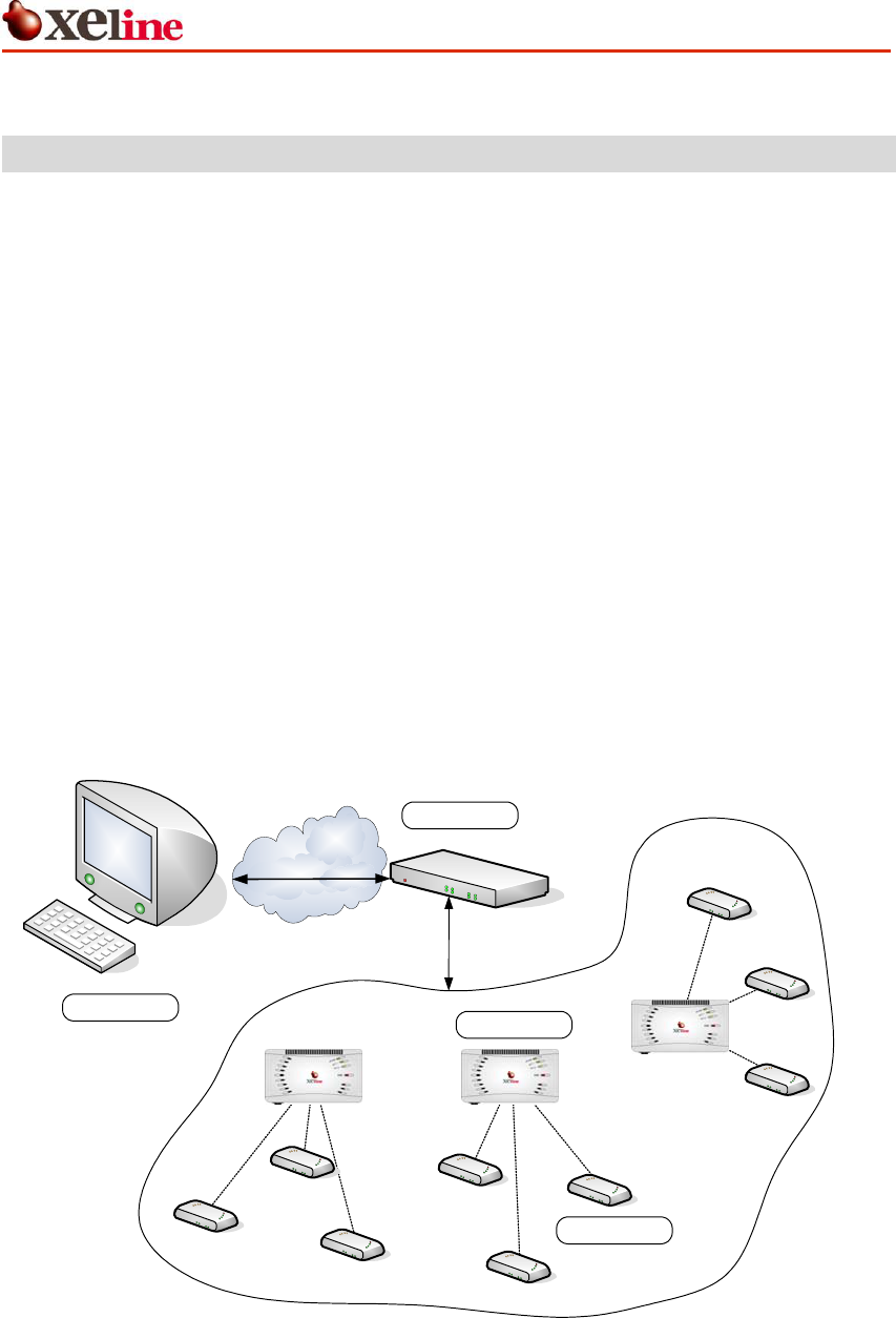
Xeline’s EU-200BX is the EMS (Element Management System) Unit that enables the remote
monitoring and management of the XPAS-200 PLC system by providing information on the
status of the PLC sites.
The EU-200BX monitors and manages network information that is characteristic only to PLC,
such as bit loading, powerline channel information, and etc., to ensure reliable network
performance. Remote configuration and firmware upgrade are also supported through the EU-
200BX for efficient setup and maintenance of the PLC units.
Figure 1 PLC EMS System Configuration
SEMS
EU-200B
SNMP Protocol
Xeline Private Protocol
MM-202B
SU-200B
WAN
X
EU-200BX Installation Manual
This document is subject to change without prior notice.
6
2. Before Installing the EU-200BX
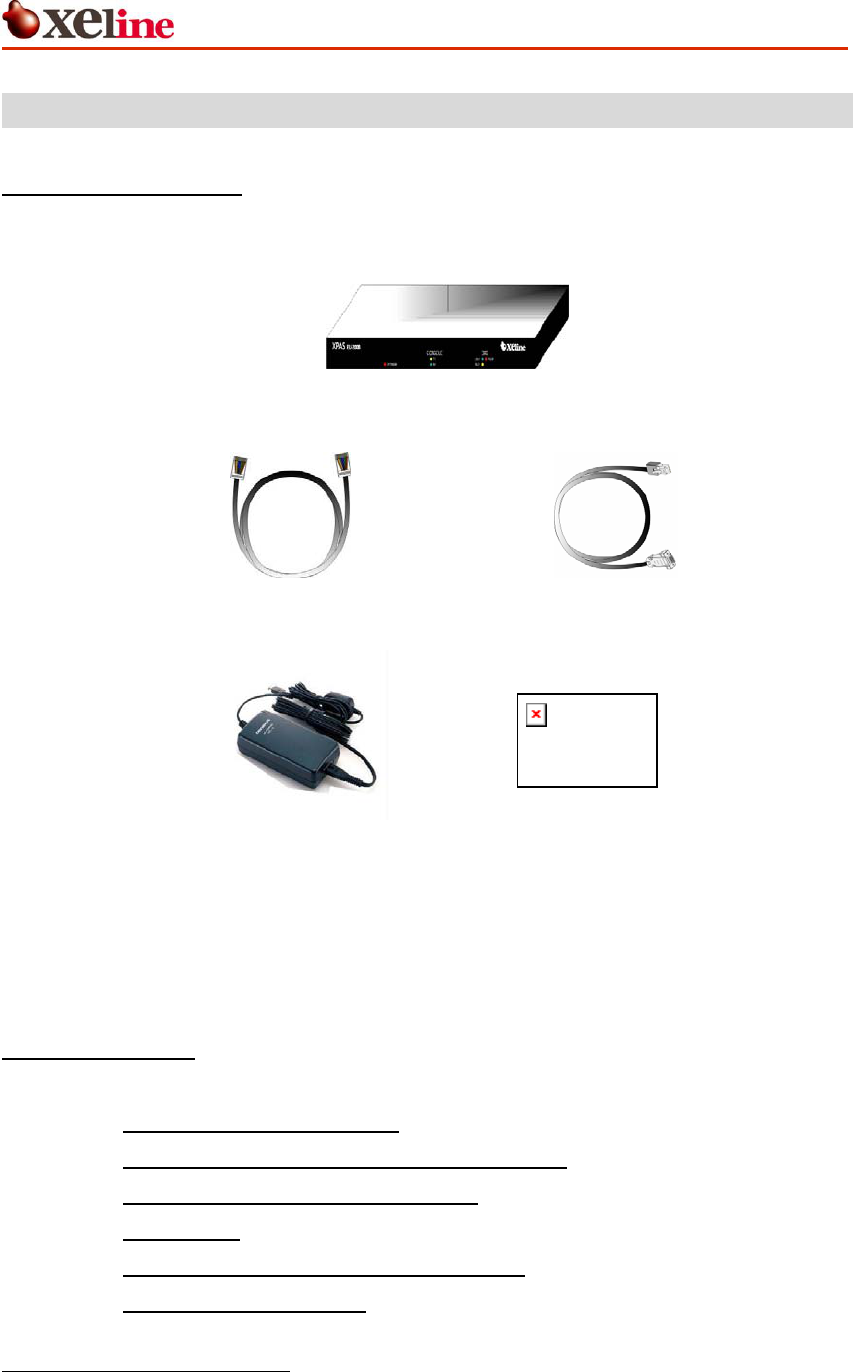
2.1 Package Contents
Before installing, first verify that you have all of the following items.
○EU-200BX EMS Unit
○1 RJ-45 Cable (Direct) ○ 1 Console Cable (RJ-45 / RS-232)
○ 1 Power Adapter ○1 Installation manual
Figure 2 EU-200BX Package Contents
If there is a missing item or any visible damage, notify your service provider or dealer
immediately.
2.2 Prerequisites
In order to install the EU-200BX, you will need the following items:
(1) Power supply for the EU-200BX
(2) Convenient access to the local backbone network
(3) Sufficient space to install the EU-200BX
(4) 1 Laptop PC
(5) 1 Switch Hub: 10base-T or higher (Optional)1
(6) 1 Cabinet (Recommended)2
1 The switch hub is not needed when connecting the EU-200BX to the PLC Master Unit.
2 In outdoor installation environments, it is recommended to use a weatherproof metal
cabinet to protect the backbone equipments, PLC Master Units, EU-200BX, switch hub and
etc.

EU-200BX Installation Manual
This document is subject to change without prior notice.
7
2.3 Safety Precautions
Please make sure to read the following guidelines before installation.
(1) Read all instructions before installing or operating the equipment. Be sure to
keep this manual for further reference.
(2) Please follow all the safety precautions and other installation procedures.
(3) Do not use this equipment near heaters or other devices that emit high heat.
(4) Do not place heavy objects on top of the EU-200BX.
(5) Install the EU-200BX near the ISP backbone or Switch Hub. Prepare a protective
metal case to house the EU-200BX, backbone equipment, and Switch Hub.
(6) Avoid the following environments:
- Areas with extremely high or low temperatures
- Areas with high humidity or high risk of flooding
- Areas where sudden changes in temperature occur
- Under direct sunlight
(In outdoor configurations, install the EU-200BX in a shady area away from
direct sunlight.)
EU-200BX Installation Manual
This document is subject to change without prior notice.
8
3. Getting to Know the EU-200BX
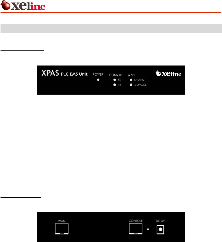
3.1 Front View
Figure 3 EU-200BX Front View
3.2 Rear View
Figure 4 EU-200BX Rear View
POWER Activates when power is turned on.
TX Blinks during console data transmission from the EU-200BX to the PC.
CONSOLE RX Blinks during console data transmission from the PC to the EU-200BX.
LNK/ACT Activates when the EU-200BX is connected to the network.
Blinks when EMS data is transmitted/received.
WAN
DUP/COL Half / Full Duplex
Detect Collision
WAN RJ-45 Ethernet port for connection to the Switch Hub or PLC Master Unit
CONSOLE Console port used to connect the EU-200BX to the PC (RJ-45 / RS-232)
RESET Resets the EU-200BX.
DC 5V External Power: DC 5V, 2A.

EU-200BX Installation Manual
This document is subject to change without prior notice.
9
3.3 Product Specifications
(1) Hardware Specifications
Category Specifications
Main Processor KS8695X
RAM 32MB SDRAM
Flash Memory 2MB X1 NOR FLASH
32MB X1 NAND FLASH
Serial Port RS232 [1 port] – Console
2 Serial Port – Data (Optional)
Ethernet Link
10/100 Base
Auto Negotiation
Auto MDIX
Power External Power : DC 5V, 2A
Dimensions 190 x 110 x 31mm (W x D x H)
Weight 664g
(2) Software Specifications
Category Specifications
Operating Software Embedded Linux (Kernel Version 2.4.x)
Supported Protocols
RFC 791 IP
RFC 793 TCP
RFC 1157 SNMP v1
RFC 1213 MIB II
RFC 1901 SNMP v2
Supported Functions
Remote OS Upgrade
Remote configuration
PLC equipment control
NMS using SNMP
Supported Services Inetd, ftp, ssh, http, tftp, SNMP
Supported Commands Busy box
EU-200BX Installation Manual
This document is subject to change without prior notice.
10
4. Installing the EU-200BX
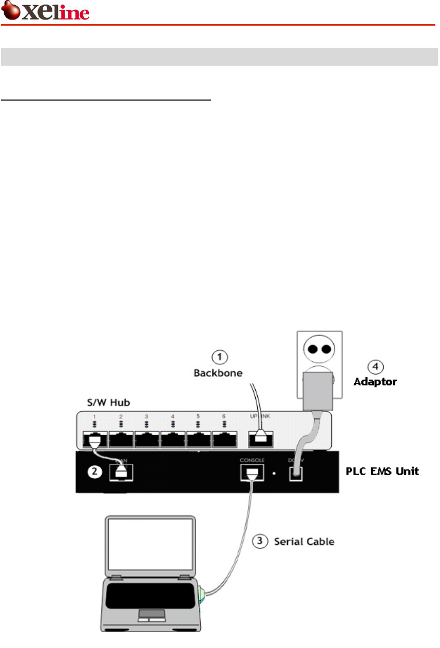
4.1 Connecting the LAN and Console
Note: The EU-200BX should be located within the same broadcasting domain as the Stations
to be managed.
① Connect the ISP backbone to the UPLINK port of the Switch Hub or PLC Master Unit.
② Insert a RJ-45 direct cable into the LAN port of the EU-200BX and connect to the LAN
port of the Switch Hub.
[Note] When connecting directly to the PLC Master Unit, insert the RJ-45 cable into
an available RJ-45 port of the PLC Master Unit.
③ Insert the RJ-45 / RS-232 cable into the CONSOLE port of the EU-200BX. Connect the
other end of the cable to the SERIAL port of the PC.
④ Connect the power adaptor to the EU-200BX and plug into the power outlet.
Figure 5 Connecting the LAN and Console
EU-200BXB
EU-200BX Installation Manual
This document is subject to change without prior notice.
11
4.2 Configuring the PC for Console Connection
Note: The following example is based on Microsoft Hyper Terminal. Other programs may be
used according to the technician’s preference.
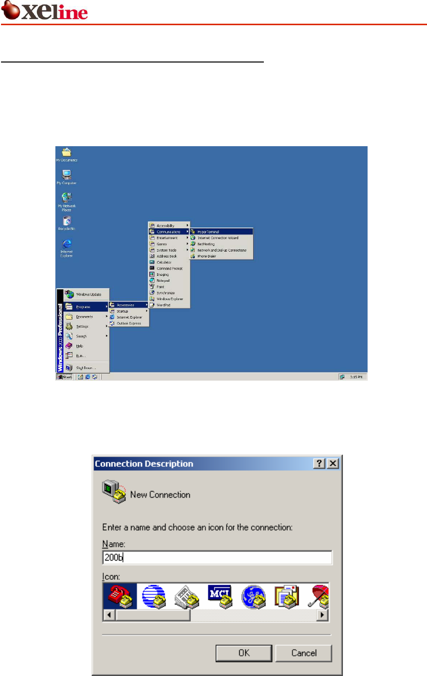
① Open the Microsoft Hyper Terminal program.
Figure 6 Microsoft Hyper Terminal
② Create a new connection. Enter a new name and select an icon.
Figure 7 Creating a New Connection
EU-200BX Installation Manual
This document is subject to change without prior notice.
12
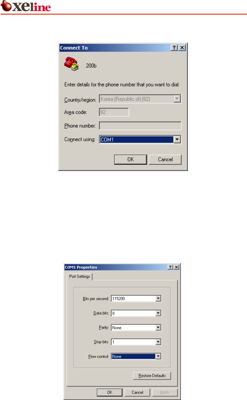
③ Assign a communication port number to use.
Figure 8 Assigning a Communication Port Number
④ Set the port settings as the following example:
A. Baud rate: 115200
B. Data bits: 8
C. Parity: None
D. Stop bits: 1
E. Flow control: None
Figure 9 Port Settings
EU-200BX Installation Manual
This document is subject to change without prior notice.
13
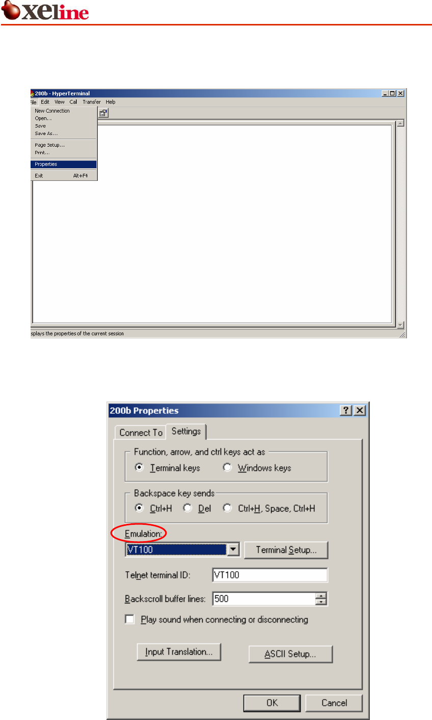
⑤ When port setting is complete, the following terminal window will appear.
Go to File Æ Properties
Figure 10 Hyper Terminal Properties
⑥ Click the Settings tab and select VT100 from the Emulation drop-down menu.
Figure 11 Emulation Setting
EU-200BX Installation Manual
This document is subject to change without prior notice.
14
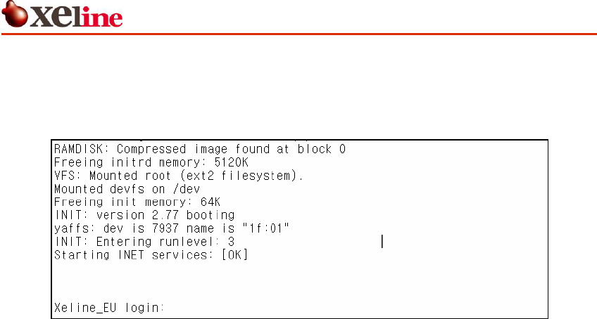
⑦ Turn on the power of the EU-200BX.
⑧ The following login prompt will appear in the Hyper Terminal window.
Figure 12 Login Prompt Window
EU-200BX Installation Manual
This document is subject to change without prior notice.
15
4.3 Setting the IP of the EU-200BX
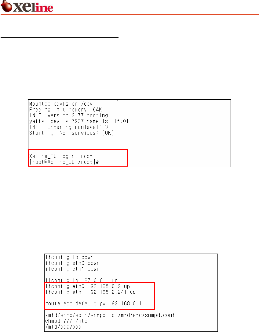
① Use the following id and password to log into the EU-200BX.
Login ID: root
Password: xeline (optional)
Figure 13 EU-200BX Login
② Type <vi /mtd/etc/start>.
③ When the following screen appears, type<i> to change to the INSERT mode.
④ Modify the IP address in “ifconfig eth0” and “route add default gw”.
[Important Note] Always use a fixed IP address. DHCP is not supported!
Figure 14 IP Configuration Example
[Note 1] To delete a typo in the IP address, you must FIRST EXIT the insert mode.
This can be done by using the <ESC> key. Then point the cursor to the letter to
delete and press the <x> key. One letter will be deleted at a time. To reenter the IP
address, type <i> to return to the insert mode.
[Note 2] If the cursor does not move using the direction keys, check if the
emulation setting is set to VT100. If the emulation is NOT SET to VT100, the cursor
may not move.
EU-200BX Installation Manual
This document is subject to change without prior notice.
16
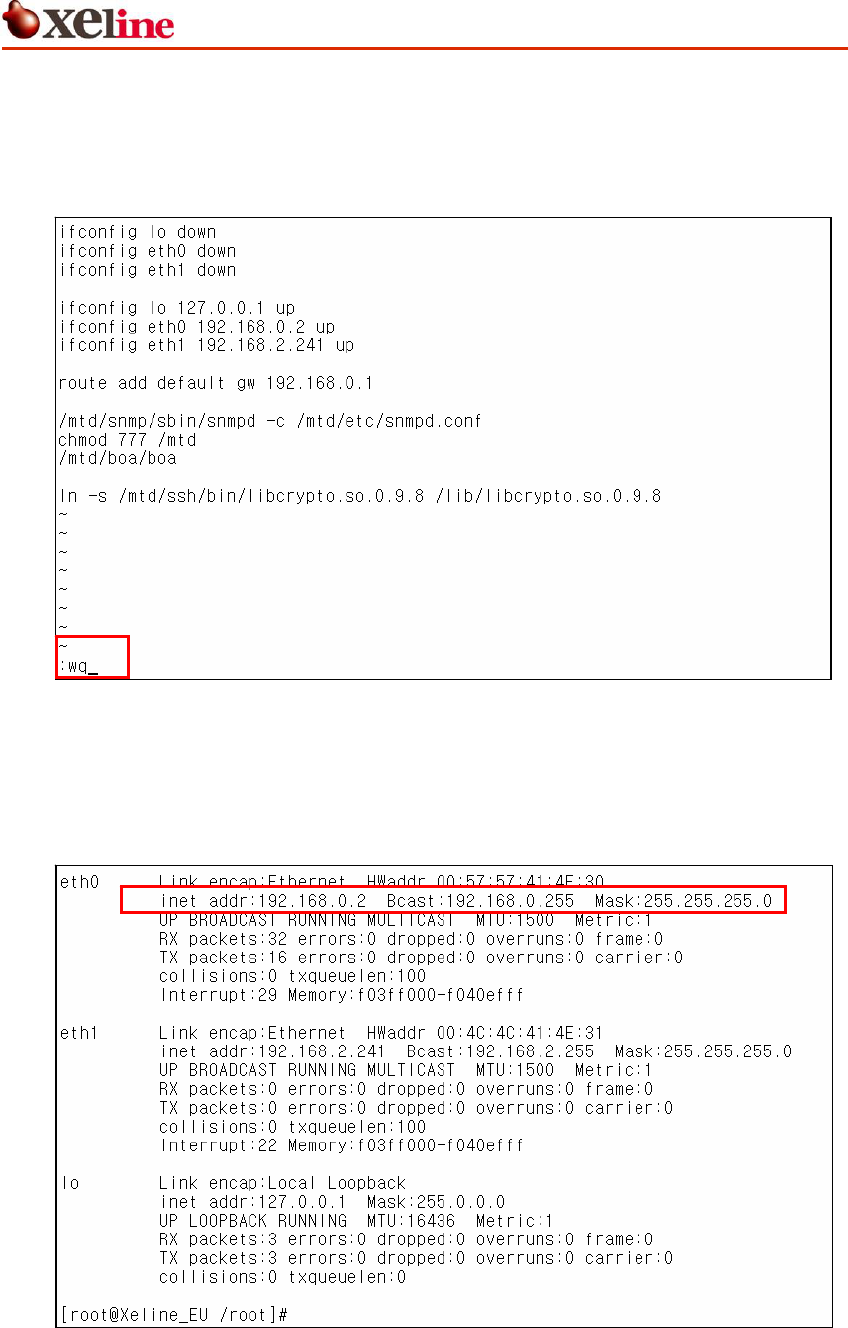
⑤ Use the <ESC> key to exit the insert mode
⑥ Type <:wq> to save the configured Trap Servers. If you do not want to save the
settings, type <:q!> to exit without saving.
Figure 15 Saving the IP Configuration
⑦ Type <reboot> to reboot the EU-200BX.
⑧ Type <ifconfig> to confirm the changed IP of the EU-200BX.
Figure 16 IP Confirmation Example
EU-200BX Installation Manual
This document is subject to change without prior notice.
17
4.4 Setting the Trap Server of the EU-200BX (Optional)
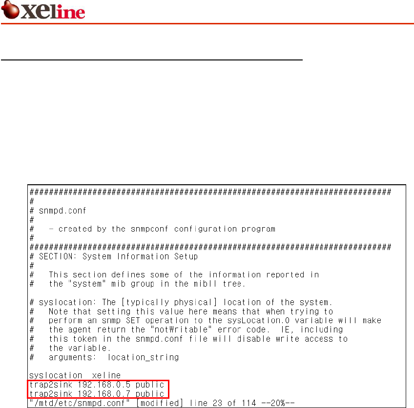
① Type <vi /mtd/etc/snmpd.conf>
② When the following screen appears, type<i> to change to the insert mode.
③ Type <trap2sink TRAP_SERVER_IP public>. The TRAP_SERVER_IP refers to the IP
address of the EMS Server to where the trap messages will be sent. It is possible to
designate multiple Trap Servers.
Figure 17 Trap Server Configuration
[Note 1] To delete a typo in the IP address, you must FIRST EXIT the insert mode.
This can be done by using the <ESC> key. Then point the cursor to the letter to
delete and press the <x> key. One letter will be deleted at a time. To reenter the IP
address, type <i> to return to the insert mode.
[Note 2] If the cursor does not move using the direction keys, check if the
emulation setting is set to VT100. If the emulation is NOT SET to VT100, the cursor
may not move.
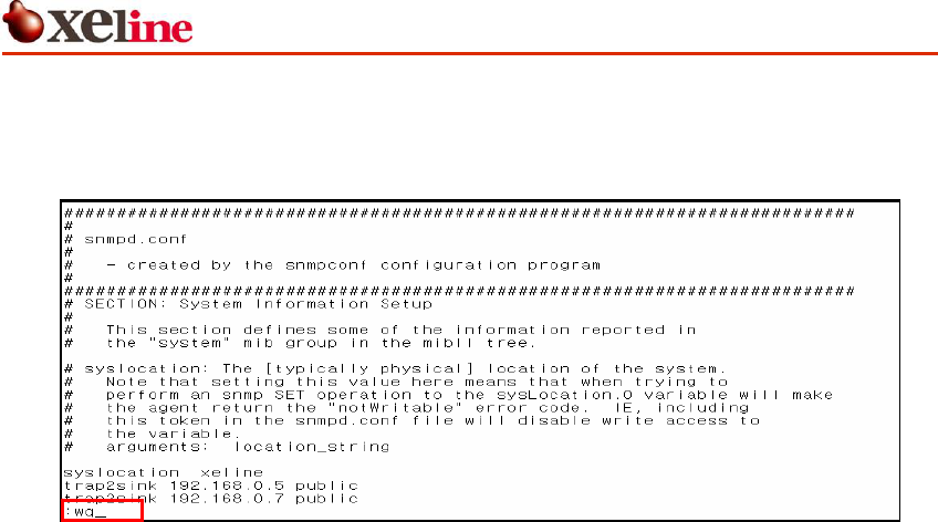
④ Use the <ESC> key to exit the insert mode.
EU-200BX Installation Manual
This document is subject to change without prior notice.
18
⑤ Type <:wq> to save the configured Trap Servers. If you do not want to save the
settings, type <:q!> to exit without saving.
Figure 18 Saving the Trap Server Configuration
⑥ Type <reboot> to reboot the EU-200BX.

EU-200BX Installation Manual
This document is subject to change without prior notice.
19
5. Trouble Shooting
Console
Problem Checklist
The POWER LED does
not activate.
Check if the power cable is firmly plugged into the EU-200BX and
power outlet.
No information is
displayed during
console connection.
① Check if the RJ-45 / RS-232 cable is firmly plugged into the
EU-200BX and PC.
② Check if the selected serial port of the Hyper Terminal
matches the actual serial port.
③ Check if the configured information such as baud rates, data
bits, parity, etc. is correct.
IP Setting
Problem Checklist
IP address of the EU-
200BX is not
configured.
Check for typos when configuring the IP address.
Connection is not
possible to the SEMS
Software. (Ping is also
not possible.)
① Connect to the EU-200BX through the console port.
② Check the IP address of the EU-200BX.
③ If the IP address is incorrect, set the appropriate IP address
to the EU-200BX. Refer to 4.3 Setting the IP of the EU-200BX
for details.
④ If the IP address is correct, check the RJ-45 cable connected
to the EU-200BX.
⑤ Perform ping tests from the EU-200BX to the SEMS Software
installed PC.
⑥ Connect to the EU-200BX using the SEMS Software.
⑦ Go to the EU-200BX main screen and download the previous
EU information. Refer to the SEMS Software User Guide 3.5.1
EU-200BX EMS Unit.
If the problem is still not solved, please contact Xeline’s Technical Support Center.

EU-200BX Installation Manual
This document is subject to change without prior notice.
20
6. Appendix
z Copyright 2005 Xeline Co., Ltd. All rights reserved.
All Xeline brand product names are trademarks of Xeline Co., Ltd.
Other product and company names mentioned herein are the trademarks of their
respective owners.
z Information in this document is subject to change without notice. No part of this document
may be reproduced or altered in any form or by any means, electronical or mechanical,
for any purpose, without the express written permission of Xeline Co., Ltd.
z Xeline Technical Support Center
Address: 5F. Seowon Bldg., 1515-4
Seocho3-dong, Seocho-gu,
Seoul 137-871, Korea
Telephone: +82 2 598 0980
Facsimile: +82 2 598 0975
E-mail: tech_support@xeline.com
Website: http://www.xeline.com