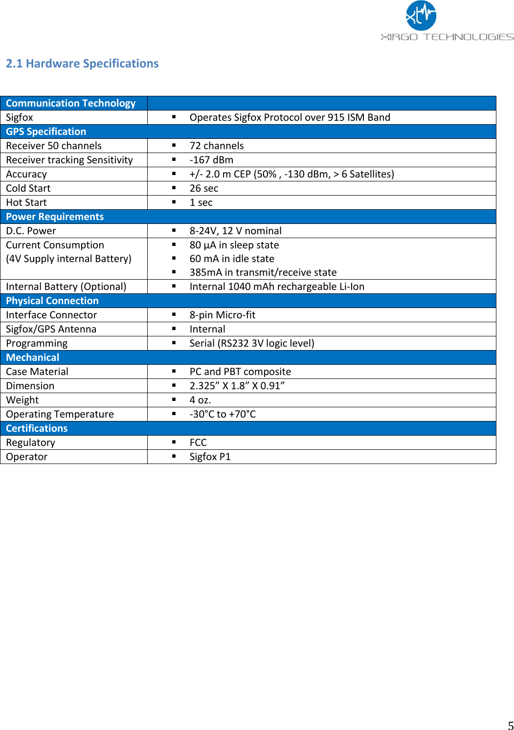
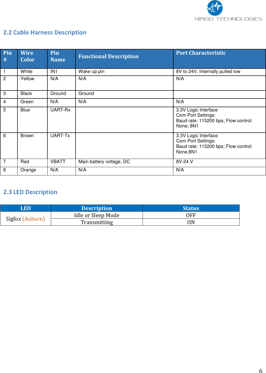
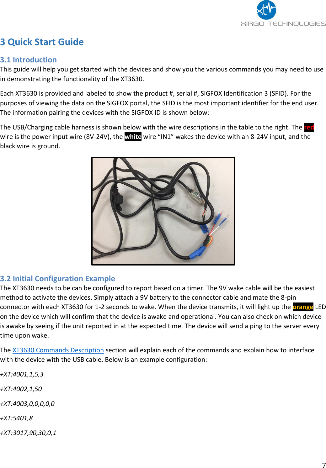
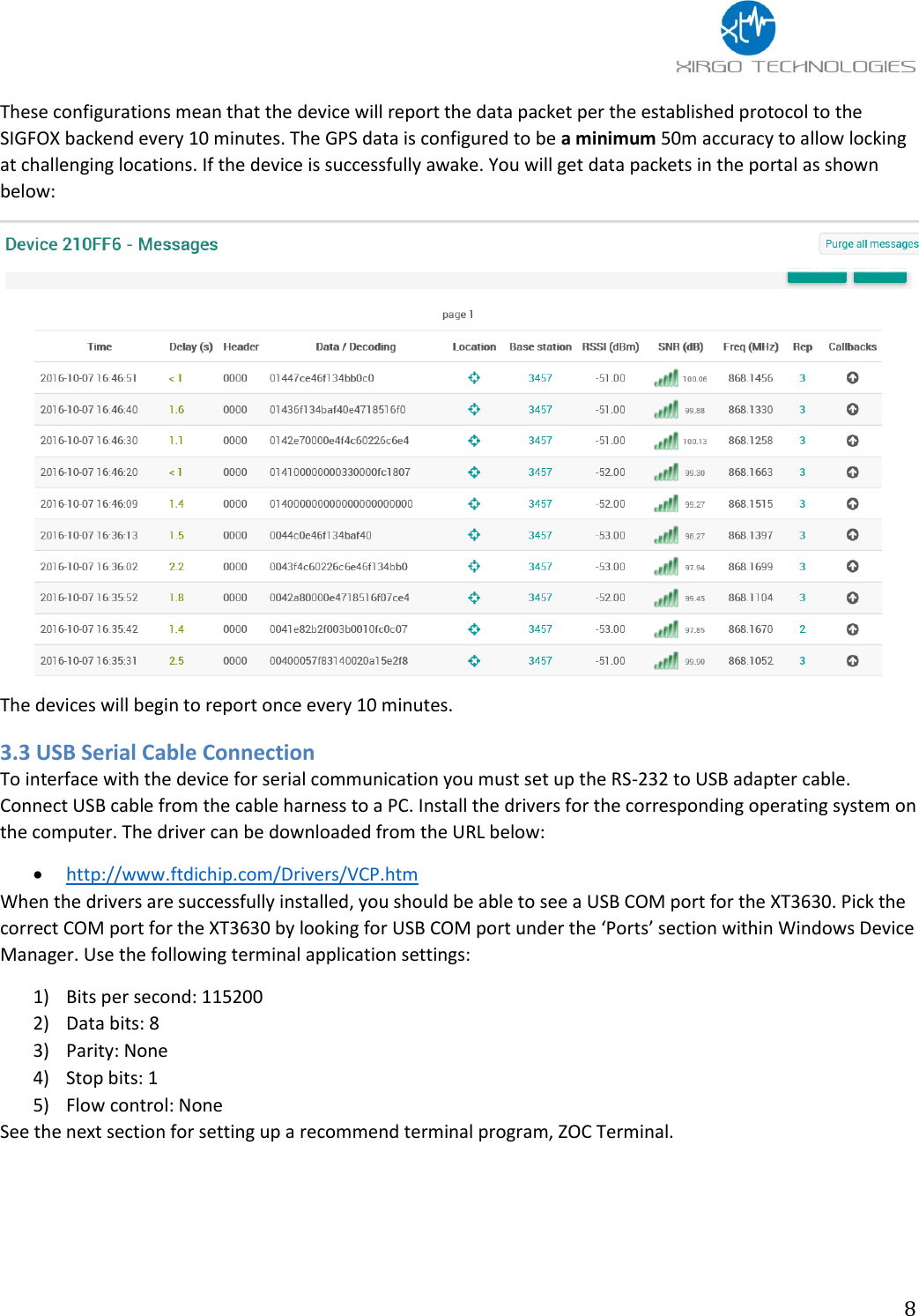
Xirgo Technologies XT3630F Asset Tracker utilizing Sigfox Communication User Manual
Xirgo Technologies Inc. Asset Tracker utilizing Sigfox Communication
UserManual.wiki
>
Xirgo Technologies
>
XT3630F User Manual
User Manual
Navigation menu
Upload a User Manual
Namespaces
Wiki Guide
HTML
PDF
Info
Views
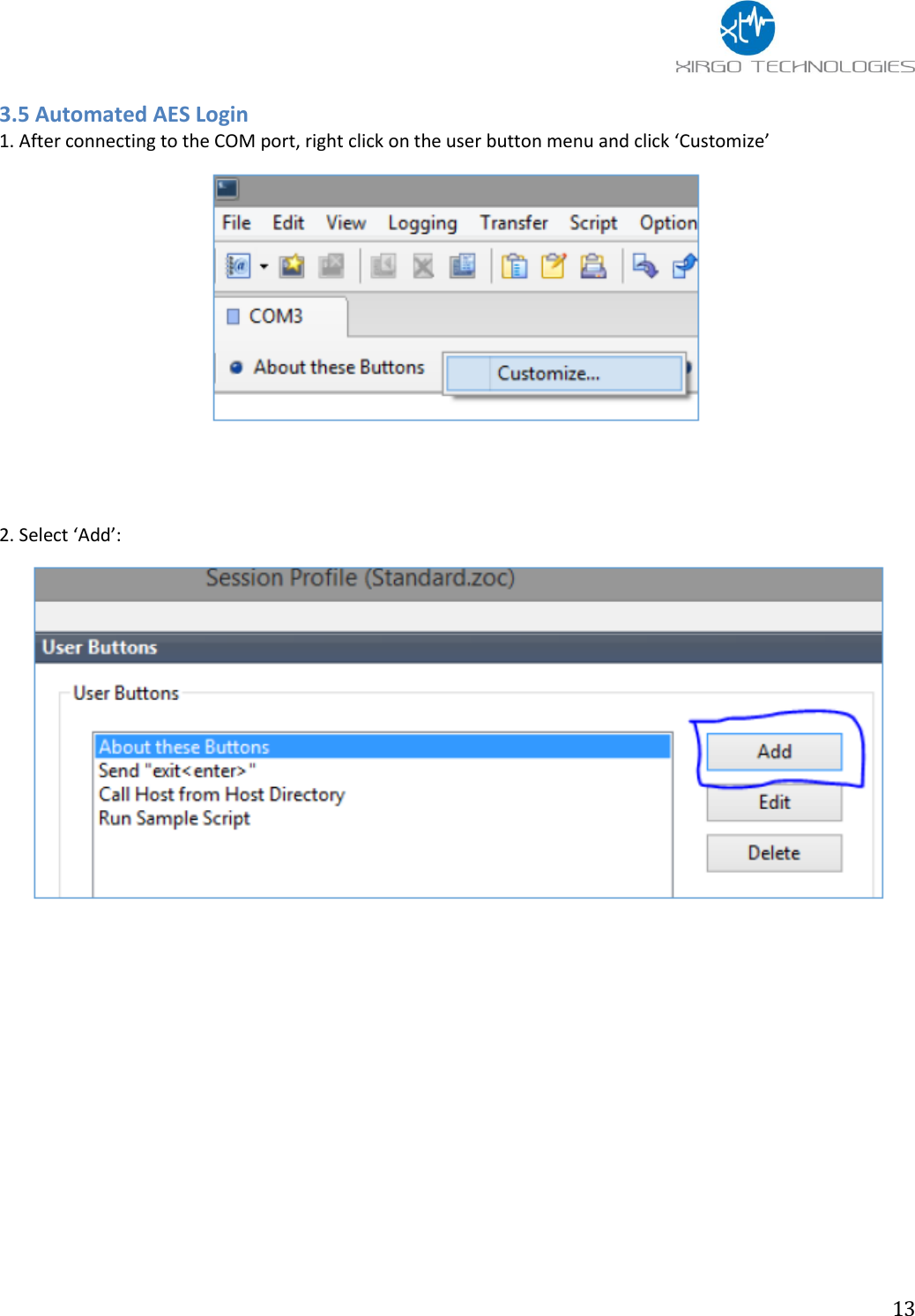
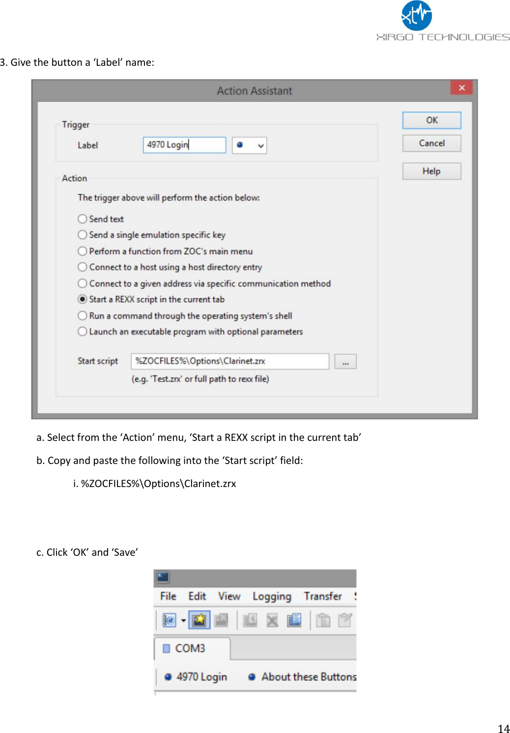
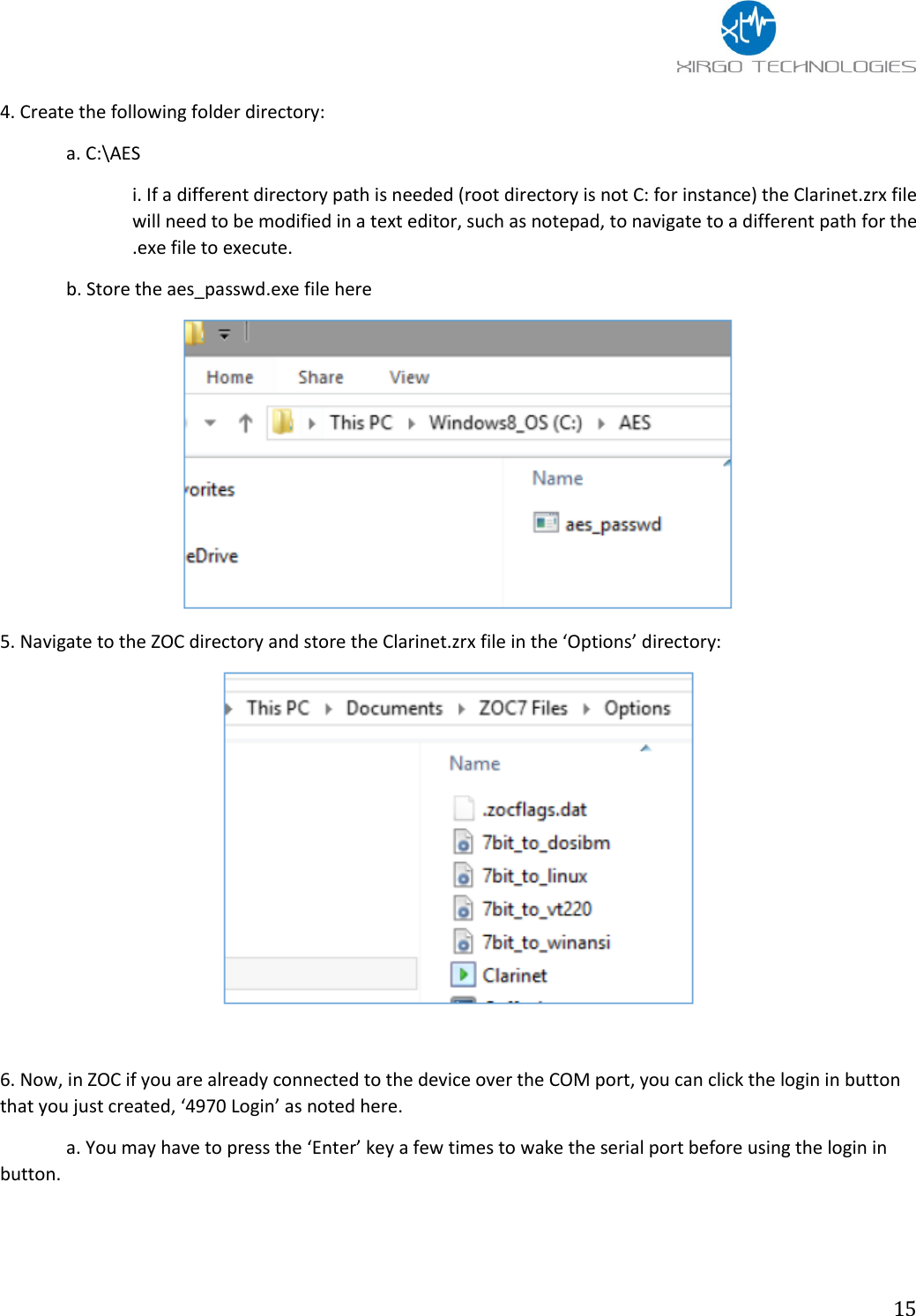
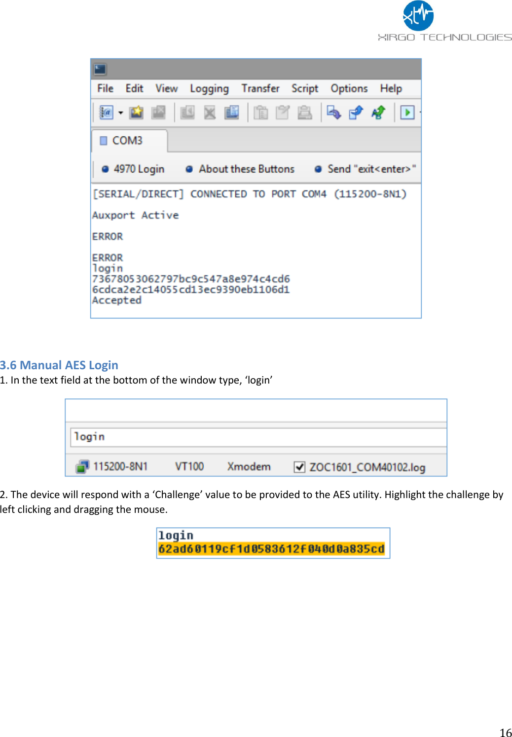
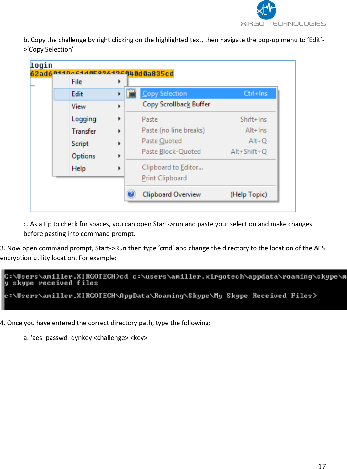
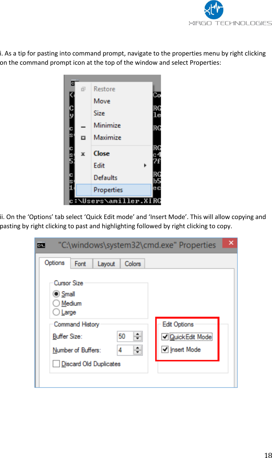
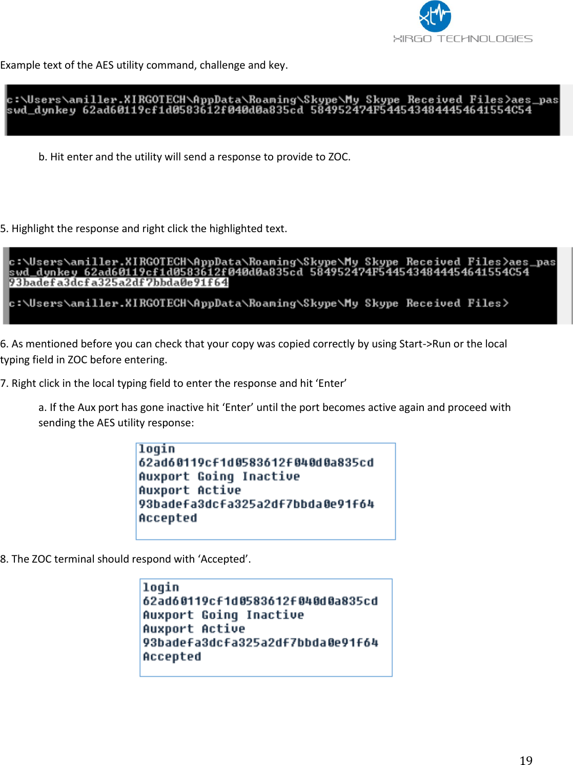
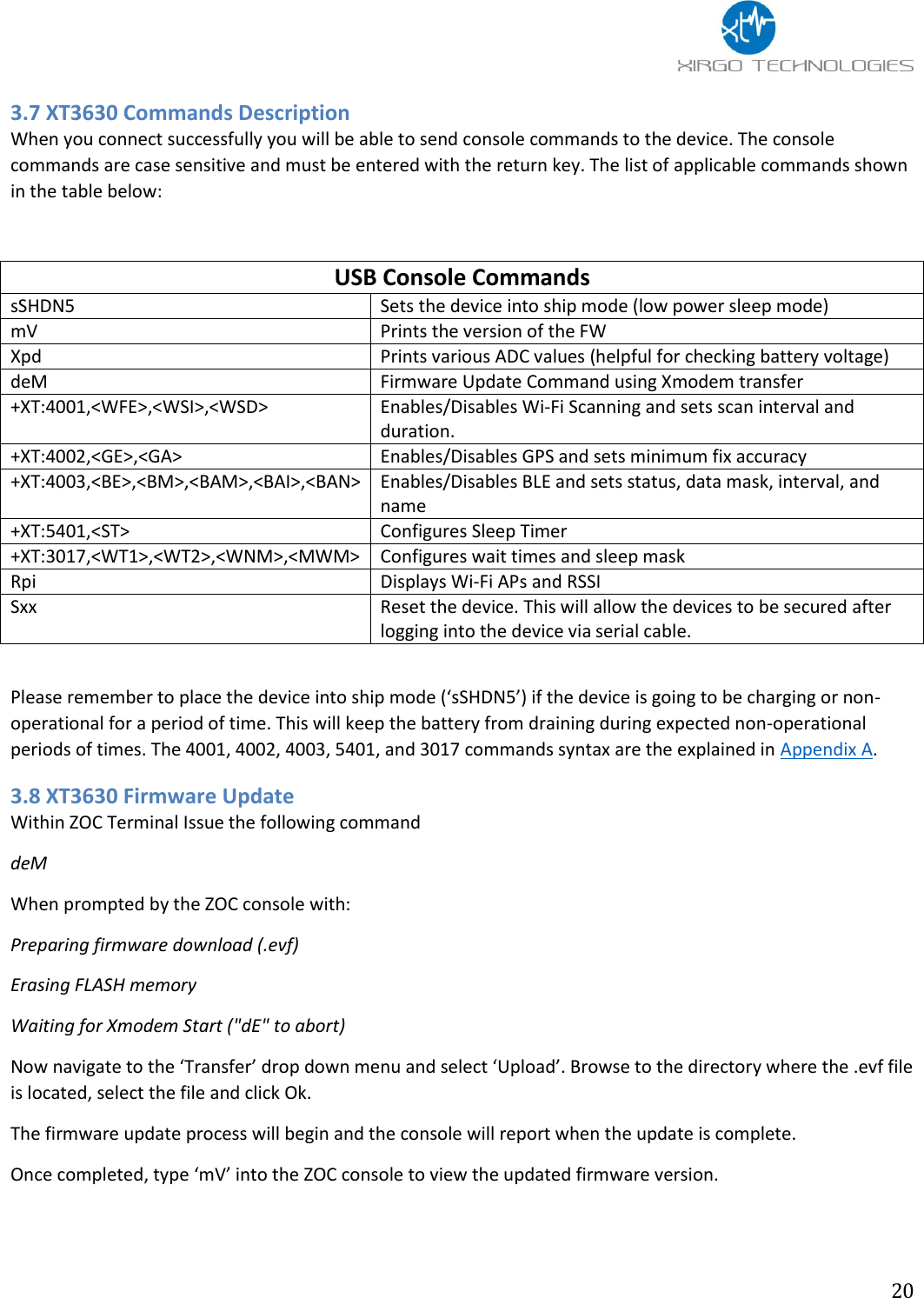
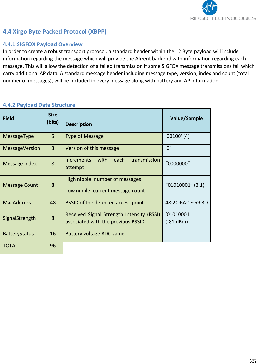
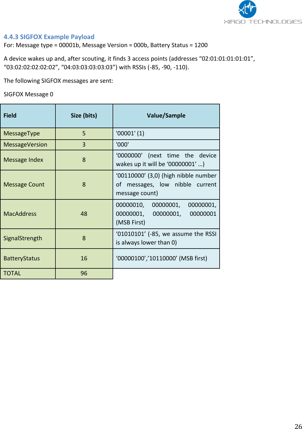
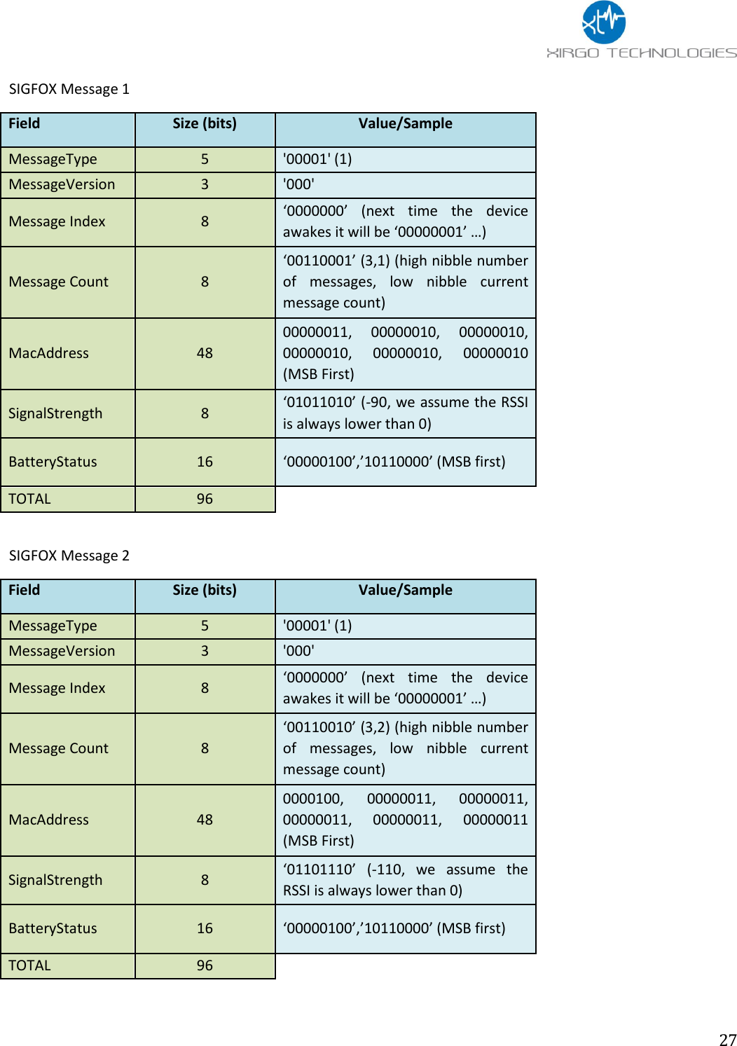
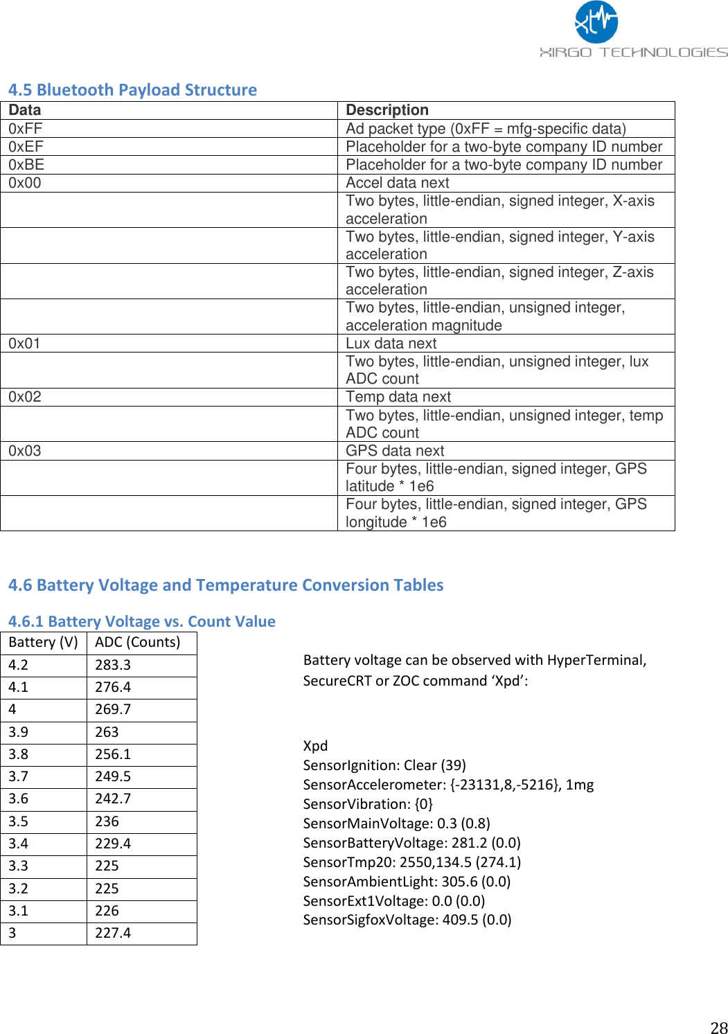
User Manual
Discussion / Help
Navigation