Xirgo Technologies XT3630F Asset Tracker utilizing Sigfox Communication User Manual
Xirgo Technologies Inc. Asset Tracker utilizing Sigfox Communication
User Manual
1
XT3630F Series User Guide
Model: XT3630F
FCC ID: GKM- XT3630F
IC: 10281A- XT3630F
Version 1

2
Table of Contents
Document Change History .......................................................................................... 2
1 Introduction ............................................................................................................ 3
1.1 Feature Matrix ................................................................................................................................................................................. 3
2 Hardware Description .............................................................................................. 4
2.1 Hardware Specifications ............................................................................................................................................................. 5
2.2 Cable Harness Description ......................................................................................................................................................... 6
2.3 LED Description .............................................................................................................................................................................. 6
3 Quick Start Guide ..................................................................................................... 7
3.1 Introduction ..................................................................................................................................................................................... 7
3.2 Initial Configuration Example ................................................................................................................................................... 7
3.3 USB Serial Cable Connection ..................................................................................................................................................... 8
3.4 Initial ZOC Console Setup ........................................................................................................................................................... 9
3.5 Automated AES Login ................................................................................................................................................................. 13
3.6 Manual AES Login ........................................................................................................................................................................ 16
3.7 XT3630 Commands Description ............................................................................................................................................ 20
3.8 XT3630 Firmware Update ........................................................................................................................................................ 20
3.9 Example Device Behavior ......................................................................................................................................................... 21
4 SIGFOX Payload Structure ...................................................................................... 22
4.1 Xirgo Simple Fragmentation Protocol Specification (XSFPS) .................................................................................... 22
4.2 Payload Data Description ......................................................................................................................................................... 23
4.3 Sample Payload Parsing Guide ............................................................................................................................................... 24
4.4 Xirgo Byte Packed Protocol (XBPP) ...................................................................................................................................... 25
4.4.1 SIGFOX Payload Overview ......................................................................................................................................................... 25
4.4.2 Payload Data Structure .............................................................................................................................................................. 25
4.4.3 SIGFOX Example Payload ........................................................................................................................................................... 26
4.5 Bluetooth Payload Structure ................................................................................................................................................... 28
4.6 Battery Voltage and Temperature Conversion Tables ................................................................................................. 28
4.6.1 Battery Voltage vs. Count Value ............................................................................................................................................. 28
4.6.2 Temperature in Celsius or Fahrenheit vs. Count Value ................................................................................................ 29
5 RS232 Based Configuration Command Protocol ...................................................... 30
5.1 Wi-Fi Configuration ..................................................................................................................................................................... 30
5.2 GPS Configuration ........................................................................................................................................................................ 30
5.3 Bluetooth Configuration............................................................................................................................................................ 31
5.4 Low Power Sleep/Wake Configuration .............................................................................................................................. 32
5.5 Sleep Alarm ................................................................................................................................................................................... 32
6. FCC/IC REGULATORY COMPLIANCE INFORMATION ............................................ 33
Document Change History
Revision
Date
Author
Changes
1.0
6/15/2017
Johnny Chen
Initial Release

3
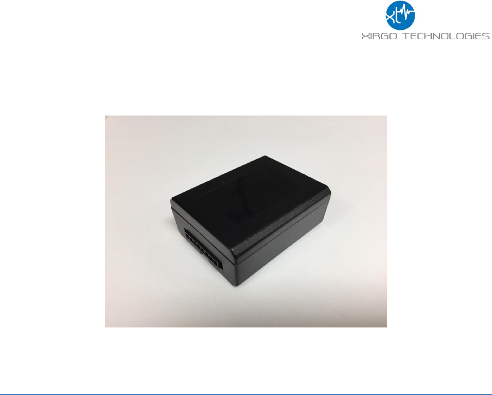
1 Introduction
XT3630F is a self-contained Narrowband LPWAN radio with integrated GPS engine and patch
antenna, accelerometer, motion detector, and 1040 mAh internal rechargeable battery. With a
low power 16-bit microprocessor and unique power management algorithm, XT3630F consumes
less than 10 µA in sleep mode and yet capable of periodic reporting of health, status and location
of remote assets. With multiple input and output ports, along with proven embedded application,
XT3630F is an ideal solution for monitoring and control of remote M2M assets where input
power availability is of concern.
1.1 Feature Matrix
Feature Description
Base Unit
Optional
Sigfox Transmitter
GPS Receiver for Tracking Applications
Location Polling
Periodic Reporting
Sleep/Wake Configuration Settings
Nearby Wi-Fi Hotspot Address Reporting
Device Diagnostics (Battery voltage, connectivity, etc.)
4
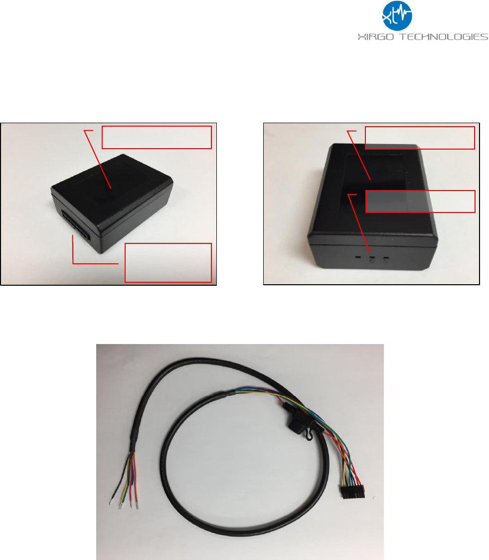
2 Hardware Description
Below is a depiction of key interfaces of the XT4970D:
The Associated Cable Harness that interfaces with the unit is shown below:
Device/FCC Label
8-Pin
Connector
LED Indicators
Device/FCC Label
5
2.1 Hardware Specifications
Communication Technology
Sigfox
Operates Sigfox Protocol over 915 ISM Band
GPS Specification
Receiver 50 channels
72 channels
Receiver tracking Sensitivity
-167 dBm
Accuracy
+/- 2.0 m CEP (50% , -130 dBm, > 6 Satellites)
Cold Start
26 sec
Hot Start
1 sec
Power Requirements
D.C. Power
8-24V, 12 V nominal
Current Consumption
(4V Supply internal Battery)
80 µA in sleep state
60 mA in idle state
385mA in transmit/receive state
Internal Battery (Optional)
Internal 1040 mAh rechargeable Li-Ion
Physical Connection
Interface Connector
8-pin Micro-fit
Sigfox/GPS Antenna
Internal
Programming
Serial (RS232 3V logic level)
Mechanical
Case Material
PC and PBT composite
Dimension
2.325” X 1.8” X 0.91”
Weight
4 oz.
Operating Temperature
-30°C to +70°C
Certifications
Regulatory
FCC
Operator
Sigfox P1

6
2.2 Cable Harness Description
Pin
#
Wire
Color
Pin
Name
Functional Description
Port Characteristic
1
White
IN1
Wake up pin
8V to 24V, Internally pulled low
2
Yellow
N/A
N/A
N/A
3
Black
Ground
Ground
4
Green
N/A
N/A
N/A
5
Blue
UART-Rx
3.3V Logic Interface
Com Port Settings:
Baud rate: 115200 bps; Flow control:
None; 8N1
6
Brown
UART-Tx
3.3V Logic Interface
Com Port Settings:
Baud rate: 115200 bps; Flow control:
None;8N1
7
Red
VBATT
Main battery voltage, DC
8V-24 V
8
Orange
N/A
N/A
N/A
2.3 LED Description
LED
Description
Status
Sigfox (Auburn)
Idle or Sleep Mode
OFF
Transmitting
ON
7
3 Quick Start Guide
3.1 Introduction
This guide will help you get started with the devices and show you the various commands you may need to use
in demonstrating the functionality of the XT3630.
Each XT3630 is provided and labeled to show the product #, serial #, SIGFOX Identification 3 (SFID). For the
purposes of viewing the data on the SIGFOX portal, the SFID is the most important identifier for the end user.
The information pairing the devices with the SIGFOX ID is shown below:
The USB/Charging cable harness is shown below with the wire descriptions in the table to the right. The red
wire is the power input wire (8V-24V), the white wire “IN1” wakes the device with an 8-24V input, and the
black wire is ground.
3.2 Initial Configuration Example
The XT3630 needs to be can be configured to report based on a timer. The 9V wake cable will be the easiest
method to activate the devices. Simply attach a 9V battery to the connector cable and mate the 8-pin
connector with each XT3630 for 1-2 seconds to wake. When the device transmits, it will light up the orange LED
on the device which will confirm that the device is awake and operational. You can also check on which device
is awake by seeing if the unit reported in at the expected time. The device will send a ping to the server every
time upon wake.
The XT3630 Commands Description section will explain each of the commands and explain how to interface
with the device with the USB cable. Below is an example configuration:
+XT:4001,1,5,3
+XT:4002,1,50
+XT:4003,0,0,0,0,0
+XT:5401,8
+XT:3017,90,30,0,1
8
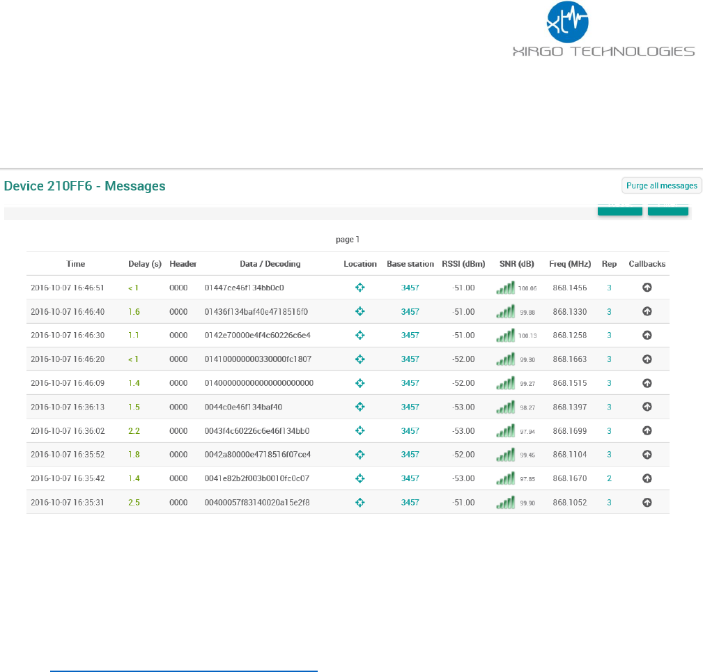
These configurations mean that the device will report the data packet per the established protocol to the
SIGFOX backend every 10 minutes. The GPS data is configured to be a minimum 50m accuracy to allow locking
at challenging locations. If the device is successfully awake. You will get data packets in the portal as shown
below:
The devices will begin to report once every 10 minutes.
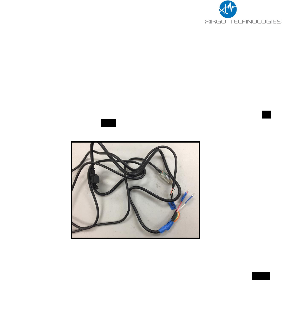
3.3 USB Serial Cable Connection
To interface with the device for serial communication you must set up the RS-232 to USB adapter cable.
Connect USB cable from the cable harness to a PC. Install the drivers for the corresponding operating system on
the computer. The driver can be downloaded from the URL below:
http://www.ftdichip.com/Drivers/VCP.htm
When the drivers are successfully installed, you should be able to see a USB COM port for the XT3630. Pick the
correct COM port for the XT3630 by looking for USB COM port under the ‘Ports’ section within Windows Device
Manager. Use the following terminal application settings:
1) Bits per second: 115200
2) Data bits: 8
3) Parity: None
4) Stop bits: 1
5) Flow control: None
See the next section for setting up a recommend terminal program, ZOC Terminal.
9
3.4 Initial ZOC Console Setup
1. Install ZOC: http://download.cnet.com/ZOC-Terminal/3000-7240_4-10125963.html
2. Connect the USB cable to your PC and the 8-pin connector to the XT-3630
3. Connect a 9V battery to the black wire (GND) and the white wire (IN1) to wake the device. You can also
connect to a DC regulated power supply to wake the device from ship mode.
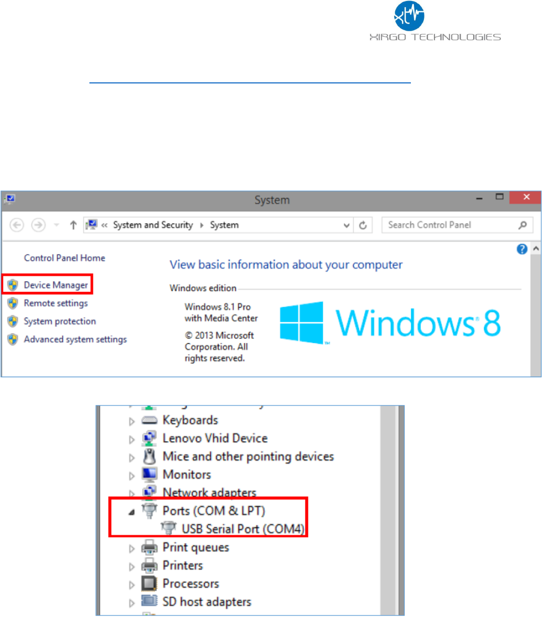
4. Navigate to Device Manager to locate the COM port associated with the XT-4970.
a. Windows Key Shortcut: Start+Pause: This will bring up your system overview and Device
Manager should be in within this new window. The Windows icon button is called, Start.
b. Windows 8.1:
5. Within Device Manager, navigate to Ports and make note of the COM port associated with the XT-4970:
6. Now, open ZOC.
10
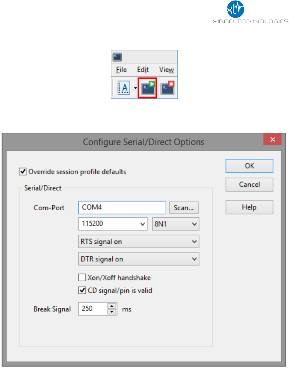
7. If the Connection setup window does not open by default, you can open or re-open the connection
settings using the green button at the top left side near the File menu:
8. You can select your COM port using the drop down menu in the middle and edit your connection
settings for Connection type and Emulation using the ‘Configure…’ buttons and the drop down menus.
a. Connection type: Serial/Direct (from the drop down menu)
b. Emulation: VT100 (from the drop down menu)
i. No ‘Configure…’ button setting changes.
11
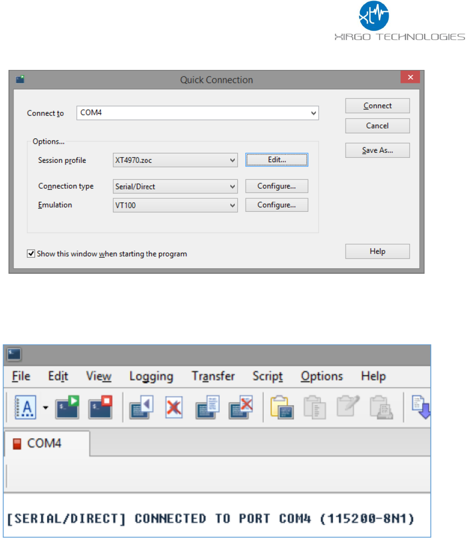
c. Main page for connection settings should look like this:
d. These connection settings can be saved in a .zoc file, by clicking the ‘Edit…’ button, verifying
your connection settings and clicking ‘Save As’.
9. Clock ‘Connect’ to begin the ZOC terminal session.
10. ZOC should report the connection as successful:
12
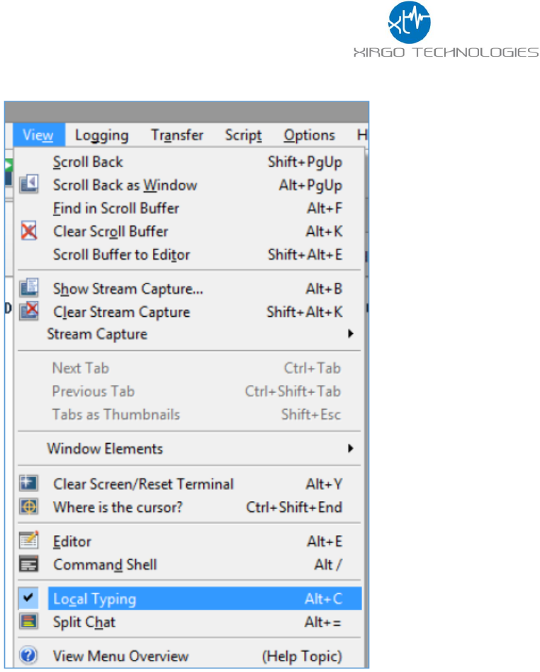
11. To enable the local typing field, navigate to View->Local Typing:
13
3.5 Automated AES Login
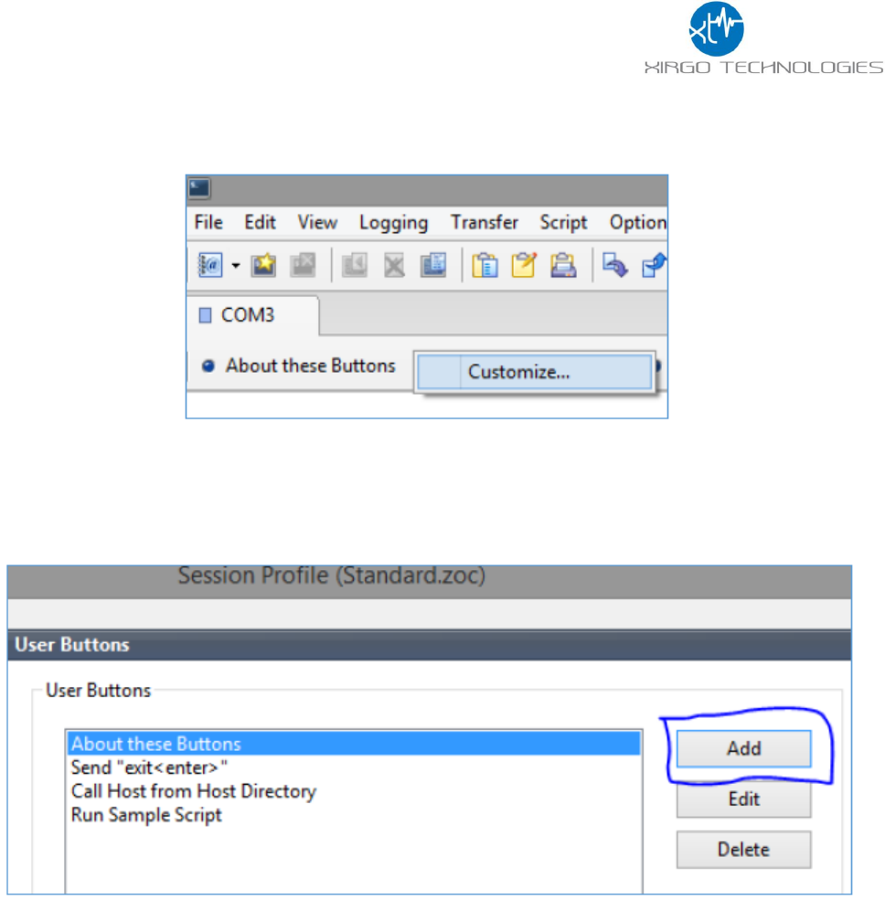
1. After connecting to the COM port, right click on the user button menu and click ‘Customize’
2. Select ‘Add’:
14
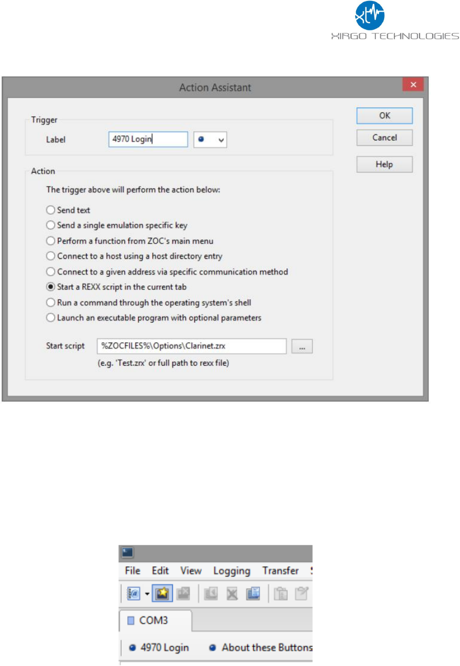
3. Give the button a ‘Label’ name:
a. Select from the ‘Action’ menu, ‘Start a REXX script in the current tab’
b. Copy and paste the following into the ‘Start script’ field:
i. %ZOCFILES%\Options\Clarinet.zrx
c. Click ‘OK’ and ‘Save’

15
4. Create the following folder directory:
a. C:\AES
i. If a different directory path is needed (root directory is not C: for instance) the Clarinet.zrx file
will need to be modified in a text editor, such as notepad, to navigate to a different path for the
.exe file to execute.
b. Store the aes_passwd.exe file here
5. Navigate to the ZOC directory and store the Clarinet.zrx file in the ‘Options’ directory:
6. Now, in ZOC if you are already connected to the device over the COM port, you can click the login in button
that you just created, ‘4970 Login’ as noted here.
a. You may have to press the ‘Enter’ key a few times to wake the serial port before using the login in
button.
16
3.6 Manual AES Login
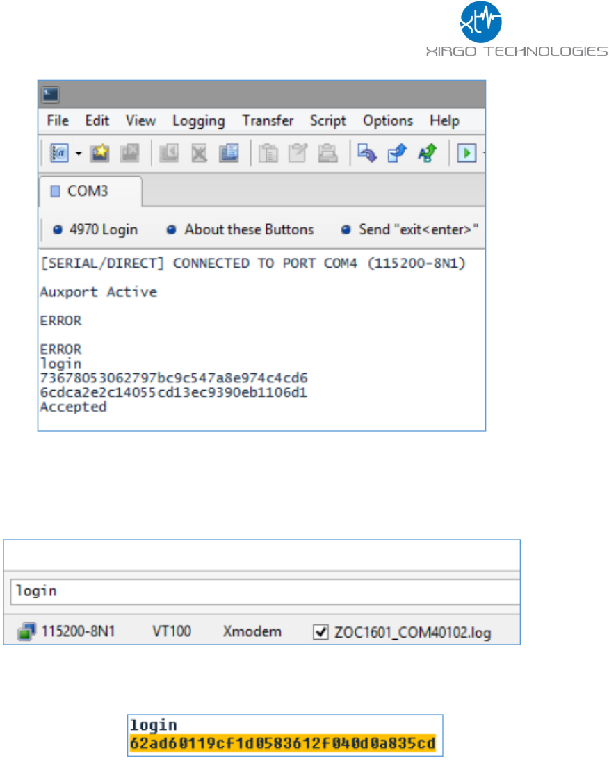
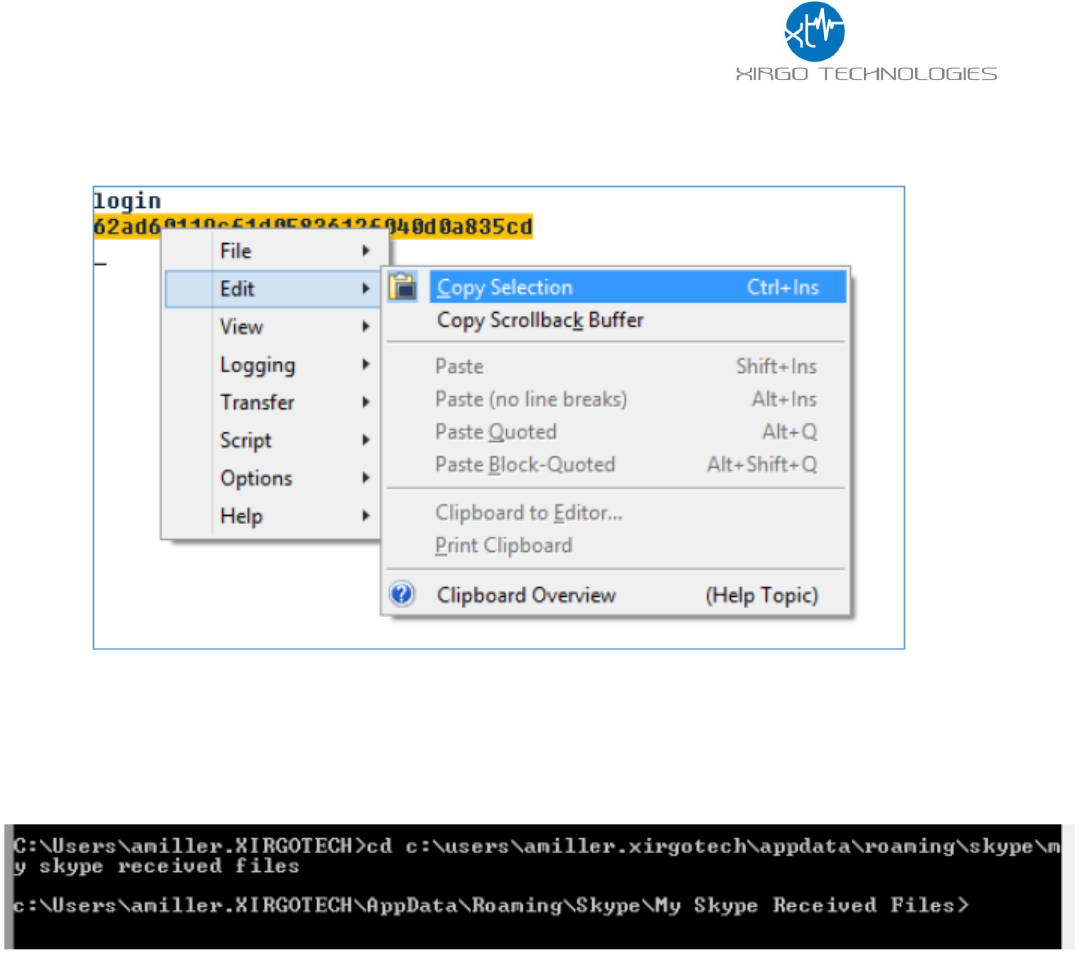
1. In the text field at the bottom of the window type, ‘login’
2. The device will respond with a ‘Challenge’ value to be provided to the AES utility. Highlight the challenge by
left clicking and dragging the mouse.
17
b. Copy the challenge by right clicking on the highlighted text, then navigate the pop-up menu to ‘Edit’-
>’Copy Selection’
c. As a tip to check for spaces, you can open Start->run and paste your selection and make changes
before pasting into command prompt.
3. Now open command prompt, Start->Run then type ‘cmd’ and change the directory to the location of the AES
encryption utility location. For example:
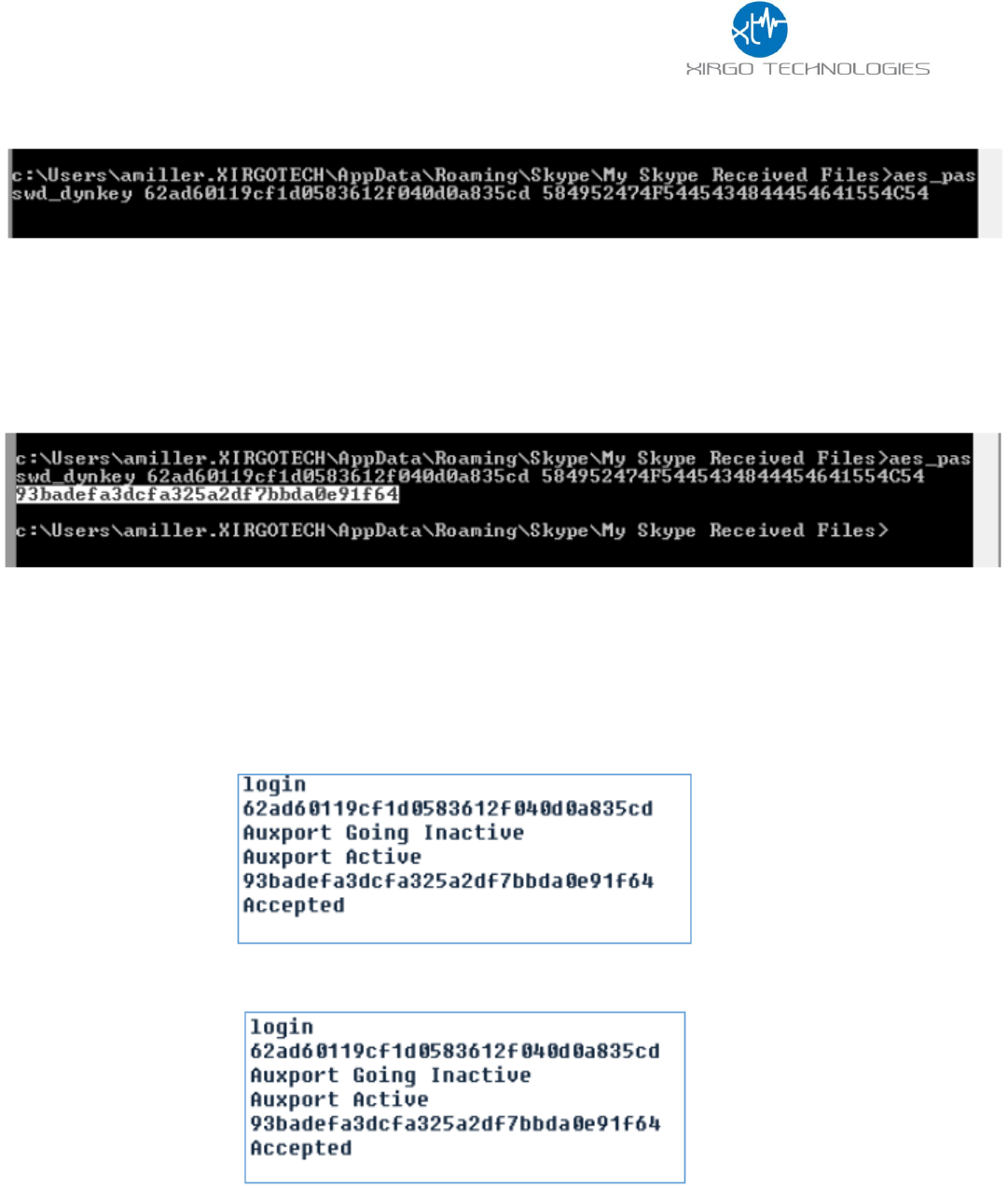
4. Once you have entered the correct directory path, type the following:
a. ‘aes_passwd_dynkey <challenge> <key>
18
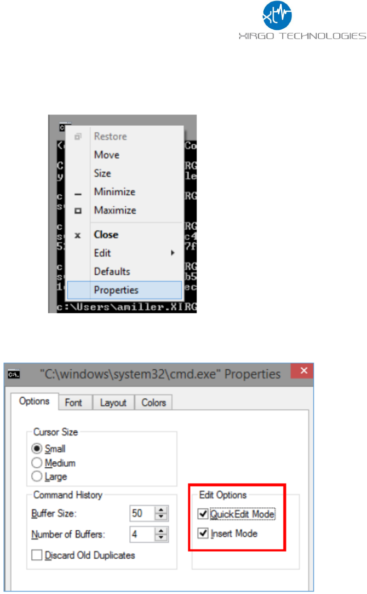
i. As a tip for pasting into command prompt, navigate to the properties menu by right clicking
on the command prompt icon at the top of the window and select Properties:
ii. On the ‘Options’ tab select ‘Quick Edit mode’ and ‘Insert Mode’. This will allow copying and
pasting by right clicking to past and highlighting followed by right clicking to copy.
19
Example text of the AES utility command, challenge and key.
b. Hit enter and the utility will send a response to provide to ZOC.
5. Highlight the response and right click the highlighted text.
6. As mentioned before you can check that your copy was copied correctly by using Start->Run or the local
typing field in ZOC before entering.
7. Right click in the local typing field to enter the response and hit ‘Enter’
a. If the Aux port has gone inactive hit ‘Enter’ until the port becomes active again and proceed with
sending the AES utility response:
8. The ZOC terminal should respond with ‘Accepted’.

20
3.7 XT3630 Commands Description
When you connect successfully you will be able to send console commands to the device. The console
commands are case sensitive and must be entered with the return key. The list of applicable commands shown
in the table below:
USB Console Commands
sSHDN5
Sets the device into ship mode (low power sleep mode)
mV
Prints the version of the FW
Xpd
Prints various ADC values (helpful for checking battery voltage)
deM
Firmware Update Command using Xmodem transfer
+XT:4001,<WFE>,<WSI>,<WSD>
Enables/Disables Wi-Fi Scanning and sets scan interval and
duration.
+XT:4002,<GE>,<GA>
Enables/Disables GPS and sets minimum fix accuracy
+XT:4003,<BE>,<BM>,<BAM>,<BAI>,<BAN>
Enables/Disables BLE and sets status, data mask, interval, and
name
+XT:5401,<ST>
Configures Sleep Timer
+XT:3017,<WT1>,<WT2>,<WNM>,<MWM>
Configures wait times and sleep mask
Rpi
Displays Wi-Fi APs and RSSI
Sxx
Reset the device. This will allow the devices to be secured after
logging into the device via serial cable.
Please remember to place the device into ship mode (‘sSHDN5’) if the device is going to be charging or non-
operational for a period of time. This will keep the battery from draining during expected non-operational
periods of times. The 4001, 4002, 4003, 5401, and 3017 commands syntax are the explained in Appendix A.
3.8 XT3630 Firmware Update
Within ZOC Terminal Issue the following command
deM
When prompted by the ZOC console with:
Preparing firmware download (.evf)
Erasing FLASH memory
Waiting for Xmodem Start ("dE" to abort)
Now navigate to the ‘Transfer’ drop down menu and select ‘Upload’. Browse to the directory where the .evf file
is located, select the file and click Ok.
The firmware update process will begin and the console will report when the update is complete.
Once completed, type ‘mV’ into the ZOC console to view the updated firmware version.
21
3.9 Example Device Behavior
This section describes XT3630 device behavior based on the following configurations:
+XT:4001,1,5,3
+XT:4002,1,50
+XT:4003,0,0,0,0,0
+XT:5401,8
+XT:3017,90,30,0,1
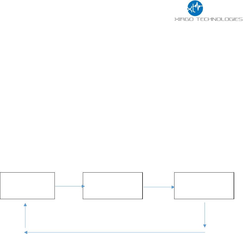
The sleep/wake configuration and the sleep timer are the most important commands to set correctly to set the
expected reporting behavior of the XT3630. The units have been configured with a sleep timer of 8 minutes.
This means that after the wait times defined in the 3017, the unit will enter low power mode for 8 minutes
until it wakes again to report per the 3017 configured timings. The flow chart below will show the expected
periodic behavior of this configured XT3630.
The 4001, 4002, and 4003 command configure how the device will gather sensor data during the 90 Second
<WT1> period. Xirgo recommends using only the default WT1 and WT2 at this time. This can be further tuned if
necessary at a later time. The 4002 is set at a minimum of 50-meter accuracy, but that can be increased or
decreased as necessary.
Bluetooth is disabled by default, but can be tested if desired. The recommended test command for Bluetooth
advertising is:
+XT:4003,1,2,15,10,BLETEST
Any BLE scanning device should be able to detect the ‘BLETEST’ name and view the available advertising data
from the device.
Sleep For 8
Minutes <ST>
Wake and gather
sensor data for 90
seconds
(WT1)
30 second window
to Transmit to
basestation
(WT2)
22
4 SIGFOX Payload Structure
4.1 Xirgo Simple Fragmentation Protocol Specification (XSFPS)
T
H
I
S
I
S
A
N
E
N
C
A
P
S
U
L
A
T
E
D
P
A
Y
L
O
A
D
!
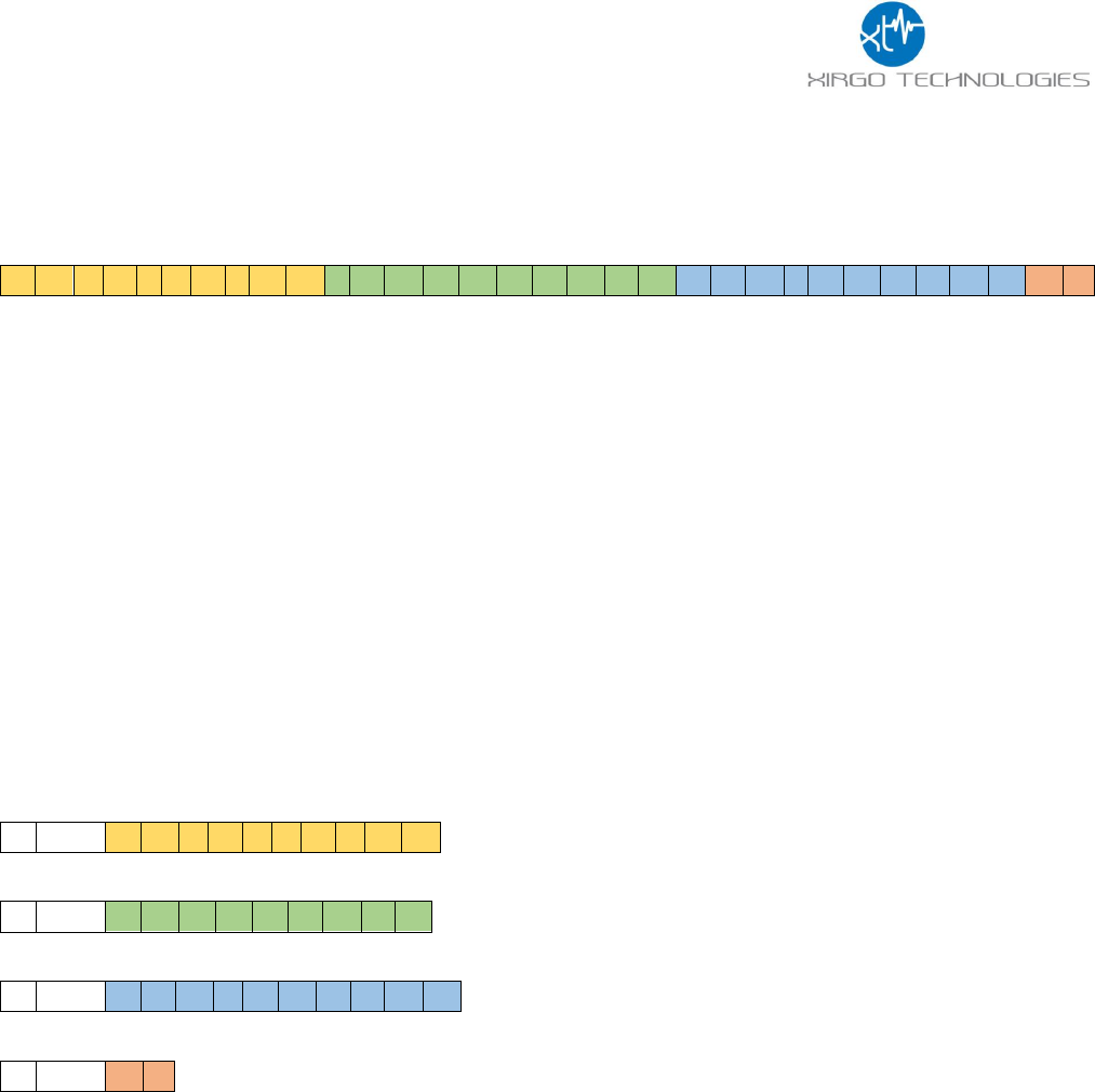
In order to transmit the data efficiently we need to create an encapsulation protocol which can support
message fragmentation.
To support this, we use a Group Index and a Message Index. Each Group contains some number of Messages.
Every Message indicates the Group, the Message Index and the total number of Messages in the Group. The
Message Index indicates ordering for payload concatenation.
The message above “THIS IS AN ENCAPSULATED PAYLOAD!” requires 4 SigFox messages to be transmitted
assuming 2 Bytes of framing information in the fragmentation protocol.
One Byte is reserved for the Group which is a logical 8-bit integer that will roll over at 256 (0-255). The second
Byte is reserved for the Message Index and the total Message Count. The Lower nibble of the 2nd Byte is the
Message Index within the Group and the upper nibble of the 2nd Byte indicates total number of messages in the
Group. ((Byte & 0x0f) + 1) == Message Index. (((Byte & 0xf0) >> 4) + 1) == Message Count. The (+1)
assumption being that there is at least one Message per Group allowing us a maximum of 16 messages per
Group and a maximum of 160 payload bytes per Group.
0
0x30
T
H
I
S
I
S
A
N
0
0x31
E
N
C
A
P
S
U
L
A
0
0x32
T
E
D
P
A
Y
L
O
A
0
0x33
D
!
The payload can contain any data. ASCII strings as shown above, or formatted binary data.
The data to be presented for this project:
1. Protocol Version, 1 Byte
2. Timestamp, 4 Bytes, Must be epoch as an absolute cannot fit in 4 Bytes. UNIX Epoch.
3. GPS Latitude, 4 Bytes
4. GPS Longitude, 4 Bytes
5. Accelerometer X, Y, Z, 6 Bytes
6. Temperature, Degrees F? C?, 2 Bytes
7. Light, Lux, 2 Bytes
8. Wi-Fi APs visible, 4 Max.

23
4.2 Payload Data Description
Offset
Size (Bytes)
Description
0
1
Payload Protocol Version
1
4
Timestamp; UNIX Epoch Offset
5
4
GPS Latitude
9
4
GPS Longitude
13
2
Accelerometer X acceleration vector
15
2
Accelerometer Y acceleration vector
17
2
Accelerometer Z acceleration vector
19
2
Temperature; tenths degrees F,C? (multiplied by 10)
21
2
Light, Lux
23
6
Highest RSSI Wi-Fi AP BSSID
29
6
2nd Highest RSSI Wi-Fi AP BSSID
35
6
3rd Highest RSSI Wi-Fi AP BSSID
41
6
4th Highest RSSI Wi-Fi AP BSSID
Highlighted fields are optional. When all of the Message Fragments are collected by the server and assembled
in order the server will have the total Message Size. 23 Bytes for no APs, 29 Bytes for 1 AP, 35 Bytes for 2 APs,
41 Bytes for 3 APs and 47 Bytes for 4 APs. Additional APs if required can be concatenated and determined
server-side based on ((Message Size – 23 Bytes) / 6 Bytes) == Number of APs at the end of the payload.
Any additional changes to the defined payload (Bytes 0 – 22) will cause an increment of the Payload Protocol
Version.

24
4.3 Sample Payload Parsing Guide
Messages:
1F 40 00 58 04 C6 EF 02 0A 16 03 F8
1F 41 E8 2B F4 FF F8 00 23 FC 18 08
1F 42 40 00 00 4C 09 D4 87 0D 13 5C
1F 43 DC 96 74 07 BD A8 D3 F7 31 0A
1F 44 08
Parsing:
Group Number: 1F
Message Count (Index + 1): 5
Note: Index is the lower nibble of the second byte of each SIGFOX message 40 -> Index 0, 41 -> Index 1, 42 ->
Index 2, etc.
Protocol Version: 00
Time Stamp: 58 04 C6 EF
1. Convert from hex to decimal: 0x5804C6EF = 1476708079
2. Open http://www.epochconverter.com/
3. Enter the seconds since epoch (Jan 1. 1970)
4. 58 04 C6 EF -> Mon, 17 Oct 2016 12:41:19 GMT
Latitude: 02 0A 16 03
1. Convert from hex to binary to check for negative value (2’s compliment format)
2. 0x020A1603 = 0010000010100001011000000011b (leading bit is zero -> positive value)
3. Convert from hex to decimal
4. 0x020A1603 = 34215427
5. Move decimal 6 places
6. 34.215427° N
Longitude: F8 E8 2B F4
1. Always check the binary conversion for a negative number (2’s compliment format)
2. 11111000111010000010101111110100= F8E82BF40x b (leading bit is 1 -> negative value)
3. Convert from binary to decimal using 2’s compliment:
a. http://www.exploringbinary.com/twos-complement-converter/
4. 11111111110001011100100000101110b <-(2’s compliment) -> --119002124
5. Move 6 decimal places: -119.002124 ° W
Accel X: FF F8 = 0xFFF8 = 1111111111111000b (leading bit is 1, 2’s compliment for negative value) = -8mG
Accel Y: 00 23 = 0x23 = 00100011b (leading bit is 0, positive value) = 35mG
Accel Z: FC 18 = 0xFC18 = 1111110000011000b (leading bit is 1, 2’s compliment, negative value) = -1000mG
Temperature: 08 40 = 0x840 = 2,112, reference the table below for approximate temperature value
Ambient Light: 00 00 (should always read 00 00 because of enclosure 0x0000 = 0 lux
Wi-Fi BSSID 1: 4C 09 D4 87 0D 13
Wi-Fi BSSID 2: 5C DC 96 74 07 BD
Wi-Fi BSSID 3: A8 D3 F7 31 0A 08

25
4.4 Xirgo Byte Packed Protocol (XBPP)
4.4.1 SIGFOX Payload Overview
In order to create a robust transport protocol, a standard header within the 12 Byte payload will include
information regarding the message which will provide the Alizent backend with information regarding each
message. This will allow the detection of a failed transmission if some SIGFOX message transmissions fail which
carry additional AP data. A standard message header including message type, version, index and count (total
number of messages), will be included in every message along with battery and AP information.
4.4.2 Payload Data Structure
Field
Size
(bits)
Value/Sample
Description
MessageType
5
Type of Message
'00100' (4)
MessageVersion
3
Version of this message
'0'
Message Index
8
Increments with each transmission
attempt
“0000000”
Message Count
8
High nibble: number of messages
Low nibble: current message count
“01010001” (3,1)
MacAddress
48
BSSID of the detected access point
48:2C:6A:1E:59:3D
SignalStrength
8
Received Signal Strength Intensity (RSSI)
associated with the previous BSSID.
‘01010001’
(-81 dBm)
BatteryStatus
16
Battery voltage ADC value
TOTAL
96

26
4.4.3 SIGFOX Example Payload
For: Message type = 00001b, Message Version = 000b, Battery Status = 1200
A device wakes up and, after scouting, it finds 3 access points (addresses “02:01:01:01:01:01”,
“03:02:02:02:02:02”, “04:03:03:03:03:03”) with RSSIs (-85, -90, -110).
The following SIGFOX messages are sent:
SIGFOX Message 0
Field
Size (bits)
Value/Sample
MessageType
5
'00001' (1)
MessageVersion
3
'000'
Message Index
8
‘0000000’ (next time the device
wakes up it will be ‘00000001’ …)
Message Count
8
‘00110000’ (3,0) (high nibble number
of messages, low nibble current
message count)
MacAddress
48
00000010, 00000001, 00000001,
00000001, 00000001, 00000001
(MSB First)
SignalStrength
8
‘01010101’ (-85, we assume the RSSI
is always lower than 0)
BatteryStatus
16
‘00000100’,’10110000’ (MSB first)
TOTAL
96

27
SIGFOX Message 1
Field
Size (bits)
Value/Sample
MessageType
5
'00001' (1)
MessageVersion
3
'000'
Message Index
8
‘0000000’ (next time the device
awakes it will be ‘00000001’ …)
Message Count
8
‘00110001’ (3,1) (high nibble number
of messages, low nibble current
message count)
MacAddress
48
00000011, 00000010, 00000010,
00000010, 00000010, 00000010
(MSB First)
SignalStrength
8
‘01011010’ (-90, we assume the RSSI
is always lower than 0)
BatteryStatus
16
‘00000100’,’10110000’ (MSB first)
TOTAL
96
SIGFOX Message 2
Field
Size (bits)
Value/Sample
MessageType
5
'00001' (1)
MessageVersion
3
'000'
Message Index
8
‘0000000’ (next time the device
awakes it will be ‘00000001’ …)
Message Count
8
‘00110010’ (3,2) (high nibble number
of messages, low nibble current
message count)
MacAddress
48
0000100, 00000011, 00000011,
00000011, 00000011, 00000011
(MSB First)
SignalStrength
8
‘01101110’ (-110, we assume the
RSSI is always lower than 0)
BatteryStatus
16
‘00000100’,’10110000’ (MSB first)
TOTAL
96

28
4.5 Bluetooth Payload Structure
Data
Description
0xFF
Ad packet type (0xFF = mfg-specific data)
0xEF
Placeholder for a two-byte company ID number
0xBE
Placeholder for a two-byte company ID number
0x00
Accel data next
Two bytes, little-endian, signed integer, X-axis
acceleration
Two bytes, little-endian, signed integer, Y-axis
acceleration
Two bytes, little-endian, signed integer, Z-axis
acceleration
Two bytes, little-endian, unsigned integer,
acceleration magnitude
0x01
Lux data next
Two bytes, little-endian, unsigned integer, lux
ADC count
0x02
Temp data next
Two bytes, little-endian, unsigned integer, temp
ADC count
0x03
GPS data next
Four bytes, little-endian, signed integer, GPS
latitude * 1e6
Four bytes, little-endian, signed integer, GPS
longitude * 1e6
4.6 Battery Voltage and Temperature Conversion Tables
4.6.1 Battery Voltage vs. Count Value
Battery (V)
ADC (Counts)
4.2
283.3
4.1
276.4
4
269.7
3.9
263
3.8
256.1
3.7
249.5
3.6
242.7
3.5
236
3.4
229.4
3.3
225
3.2
225
3.1
226
3
227.4
Battery voltage can be observed with HyperTerminal,
SecureCRT or ZOC command ‘Xpd’:
Xpd
SensorIgnition: Clear (39)
SensorAccelerometer: {-23131,8,-5216}, 1mg
SensorVibration: {0}
SensorMainVoltage: 0.3 (0.8)
SensorBatteryVoltage: 281.2 (0.0)
SensorTmp20: 2550,134.5 (274.1)
SensorAmbientLight: 305.6 (0.0)
SensorExt1Voltage: 0.0 (0.0)
SensorSigfoxVoltage: 409.5 (0.0)
SensorWifiVoltage: 398.6 (0.0)

29
4.6.2 Temperature in Celsius or Fahrenheit vs. Count Value
Chamber Temp
(Celsius)
Unit 1 Temp Data
Unit 1 Raw Count
Unit 1 Celsius count
Unit 1 Fahrenheit Count
-35
3036,131.5 (268.7)
3036
131.5
268.7
-25
2873,132.5 (270.5)
2873
132.5
270.5
-15
2713,133.5 (272.3)
2713
133.5
272.3
-5
2548,134.5 (274.1)
2548
134.5
274.1
5
2388,135.5 (275.9)
2388
135.5
275.9
15
2226,136.5 (277.7)
2226
136.5
277.7
25
2072,137.4 (279.4)
2072
137.4
279.4
35
1911,138.4 (281.2)
1911
138.4
281.2
45
1766,139.3 (282.8)
1766
139.3
282.8
55
1605,140.3 (284.6)
1605
140.3
284.6
65
1448,141.3 (286.3)
1448
141.3
286.3
75
1287,142.3 (288.1)
1287
142.3
288.1
85
1130,143.2 (289.8)
1130
143.2
289.8
Chamber Temp
(Celsius)
Unit 2 Temp Data
Unit 2 Raw Count
Unit 2 Celsius Count
Unit 2 Fahrenheit Count
-35
3098,131.1 (268.0)
3098
131.1
268.0
-25
2929,132.2 (269.9)
2929
132.2
269.9
-15
2766,133.2 (271.7)
2766
133.2
271.7
-5
2598,134.2 (273.6)
2598
134.2
273.6
5
2431,135.2 (275.4)
2431
135.2
275.4
15
2264,136.2 (277.2)
2264
136.2
277.2
25
2100,137.3 (279.1)
2100
137.3
279.1
35
1931,138.3 (280.9)
1931
138.3
280.9
45
1791,139.2 (282.5)
1791
139.2
282.5
55
1628,140.2 (284.3)
1628
140.2
284.3
65
1466,141.2 (286.1)
1466
141.2
286.1
75
1304,142.2 (287.9)
1304
142.2
287.9
85
1145,143.1 (289.7)
1145
143.1
289.7

30
5 RS232 Based Configuration Command Protocol
5.1 Wi-Fi Configuration
Type
Syntax
Response
ASCII
Set
+XT:4001,<WE>,<WSI>,<WSD>
$$<UID>,4001,<WE>,<WSI>,<WSD>##
Read
+XT:4001?
$$<UID>4001,<WE>,<WSI>,<WSD>##
Parameter
Type
Description
<WE>
Numeric
Wi-Fi Enable
1: Enabled
0: Disabled
Default is 0 (Disabled)
<WSI>
Numeric
Wi-Fi Scanning Interval
Valid Range is 0 – 86400 (seconds)
0: Disabled
Default is 0 (Disabled)
<WSD>
Wi-Fi Scanning Duration
Valid Range is 0 – 86400 (seconds)
0: Disabled
Default is 0 (Disabled)
NOTE: If Scanning duration is larger than scanning interval, then the Wi-Fi module will be permanently
scanning.
5.2 GPS Configuration
Type
Syntax
Response
ASCII
Set
+XT:4002,<GE>,<GI>
$$<UID>,4002,<GE>,<GA>##
Read
+XT:4002?
$$<UID>,4002,<GE>,<GA>##
Parameter
Type
Description
<GE>
Numeric
GPS Enable
1: Enabled
0: Disabled
Default is 0 (Disabled)
<GA>
Numeric
GPS minimum accuracy
Valid Range is 0 – 255 (meters)
0: Disabled
Default is 0 (Disabled)

31
5.3 Bluetooth Configuration
Type
Syntax
Response
ASCII
Set
+XT:4003, <BE>,<BM>,<BAM>,<BAI>,<BAN>
$$<UID>,4003, <BE>,<BM>,<BAM>,<BAI>,<BAN>##
Read
+XT:4003?
$$<UID>,4003, <BE>,<BM>,<BAM>,<BAI>,<BAN>##
Parameter
Type
Description
<BE>
Numeric
Bluetooth Enable
1: Enabled
0: Disabled
Default is 0 (Disabled)
<BM>
Numeric
Bluetooth Mode
0: Idle
1: Scanner
2: Advertise
<BAM>
Numeric
Bluetooth Advertising Data Mask
0: Disabled
1: Accelerometer
2: Lux
4: Temp
8: GPS
16: Serial#
<BAI>
Numeric
Bluetooth Advertising Interval
Valid Range is 0 – 86400 (seconds)
0: Disabled
Default is 0 (Disabled)
<BAN>
Numeric
APN Username
Maximum 12 characters accepted
Default value is “”

32
5.4 Low Power Sleep/Wake Configuration
Type
Syntax
Response
ASCII
Set
+XT:3017,<WT1>,<WT2>,<WMN>,<MWM>
$$<UID>,3017,<WT1>,<WT2>,<WMN>,<MWM>##
Read
+XT:3017?
$$<UID>,3017,<WT1>,<WT2>,<WNM>,<MWM>##
Parameter
Type
Description
<WT1>
Numeric
Pre-Alert Maximum Wait Time
Valid Range is 0 – 32767 (seconds)
Default Value is 1
<WT2>
Numeric
Post-Alert Wait Time
Valid Range is 0 – 32767 (seconds)
Default Value is 1
<WNM>
Numeric
Shutdown/Sleep Notification Time
Default Value is 0 (Disabled)
<MWM>
Numeric
Wake Mask
0: Disabled
1: Sleep Time
2: Motion Wake
4: Motion/No-Motion Periods & Thresholds
8: Daily Wake
16: Wake-Pin (Input1/Ignition)
32: External Power
64: Battery Good
5.5 Sleep Alarm
Type
Syntax
Response
ASCII
Set
+XT:5401,<ST>
$$<UID>,5401,<ST>##
Read
+XT:5401?
$$<UID>,5401,<ST>##
Parameter
Type
Description
<ST>
Numeric
Sleep Alarm Timer
Valid Range is 1 – 32767 (minutes)
1 Minute Increments
Default Value is 0 (Disabled)

33
6. FCC/IC REGULATORY COMPLIANCE INFORMATION
This equipment with FCC-ID: GKM-XT3630F and IC-ID: 10281A- XT3630F, Model: XT3630F
is subject to the Federal Communications Commission (FCC) and Industry Canada (IC) rules.
NOTICE:
Changes or modifications not expressly approved by the party responsible for compliance could void the user's
authority to operate the equipment.
This device complies with Part 15 of the FCC Rules. Operation is subject to the following two conditions: (1) this
device may not cause harmful interference, and (2) this device must accept any interference received, including
interference that may cause undesired operation.
This device complies with radiation exposure limits set forth for an uncontrolled environment and meets radio
frequency (RF) Exposure Guidelines. This equipment should be installed and operated by keeping the device at
least 20cm from a person’s body.
Antenna Statement
Under Industry Canada regulations, this radio transmitter may only operate using an antenna of a type
and maximum (or lesser) gain approved for the transmitter by Industry Canada. To reduce potential radio
interference to other users, the antenna type and its gain should be so chosen that the equivalent
isotropically radiated power (e.i.r.p.) is not more than that necessary for successful communication.
Conformément à la réglementation d'Industrie Canada, le présent émetteur radio peut
fonctionner avec une antenne d'un type et d'un gain maximal (ou inférieur) approuvé pour
l'émetteur par Industrie Canada. Dans le but de réduire les risques de brouillage radioélectrique à
l'intention des autres utilisateurs, il faut choisir le type d'antenne et son gain de sorte que la puissance
isotrope rayonnée équivalente (p.i.r.e.) ne dépasse pas l'intensité nécessaire à l'établissement d'une
communication satisfaisante.
Licence exempt
This device complies with Industry Canada licence-exempt RSS standard(s). Operation is subject to the
following two conditions:
(1) this device may not cause interference, and
(2) this device must accept any interference, including interference that may cause undesired operation
of the device.
Le présent appareil est conforme aux CNR d'Industrie Canada applicables aux appareils radio
exempts de licence. L'exploitation est autorisée aux deux conditions suivantes :
(1) l'appareil ne doit pas produire de brouillage, et
(2) l'utilisateur de l'appareil doit accepter tout brouillage radioélectrique subi, même si le brouillage est
susceptible d'en compromettre le fonctionnement.