Xirgo Technologies XT4820 GPS Asset Tracking Device User Manual user guide
Xirgo Technologies Inc. GPS Asset Tracking Device user guide
UserManual.wiki
>
Xirgo Technologies
>
XT4820 User Manual
>
user guide
Contents
1.
user guide
2.
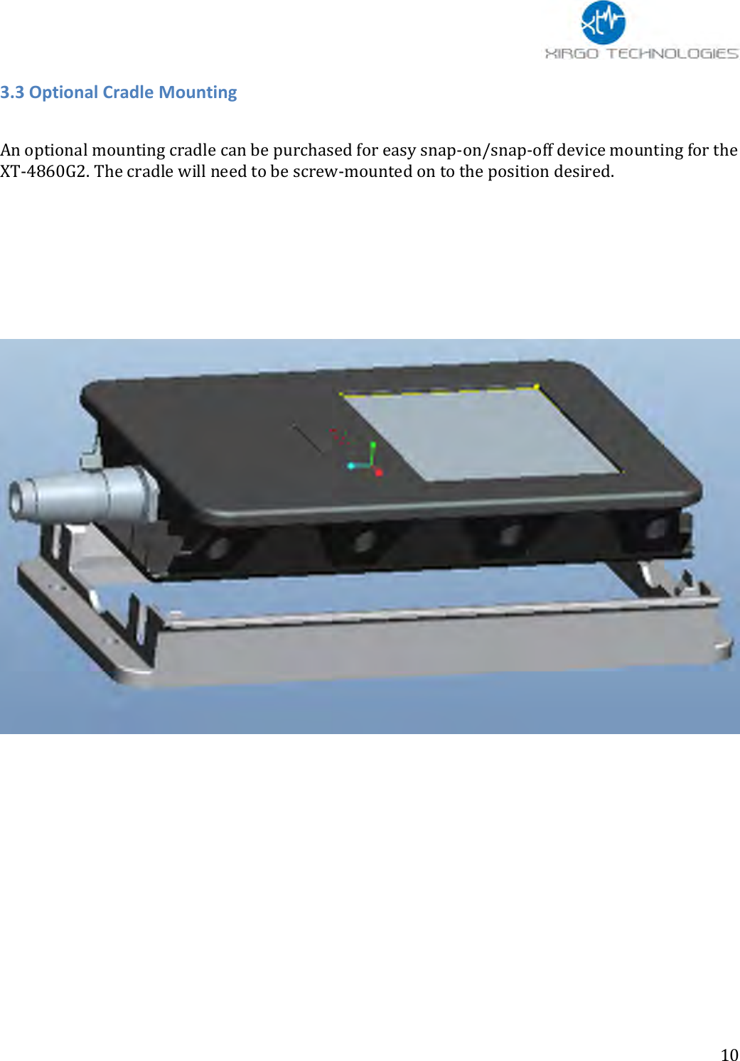
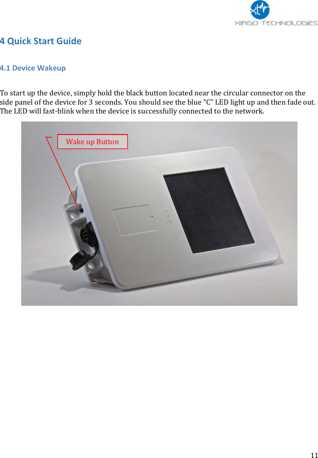
user manual
user guide
Navigation menu
Upload a User Manual
Namespaces
Wiki Guide
HTML
PDF
Info
Views
User Manual
Discussion / Help
Navigation