Xirgo Technologies XT4820 GPS Asset Tracking Device User Manual user guide
Xirgo Technologies Inc. GPS Asset Tracking Device user guide
Contents
- 1. user guide
- 2. user manual
user guide
1
XT-4860G2 User Guide
Model: XT-4860G2
FCC ID: GKM-XT4820
IC ID: IC: 10281A-XT4820
Version 1.0

2

3
Table of Contents
Document Change History .......................................................................................... 4
1 Introduction ............................................................................................................ 5
1.1 Feature Matrix ................................................................................................................................................................................. 5
2 Hardware Description .............................................................................................. 6
2.1 Hardware Specifications ............................................................................................................................................................. 7
2.2 Cable Harness Description ......................................................................................................................................................... 8
2.3 LED Description .............................................................................................................................................................................. 8
3 Device Mounting Options ........................................................................................ 9
3.1 Screw Mounting .............................................................................................................................................................................. 9
3.2 Magnetic Mounting ........................................................................................................................................................................ 9
3.3 Optional Cradle Mounting ........................................................................................................................................................ 10
4 Quick Start Guide ................................................................................................... 11
4.1 Device Wakeup ............................................................................................................................................................................. 11
4.2 Configuring the Device via SMS .............................................................................................................................................. 12
4
Document Change History
Revision
Date
Author
Changes
1.0
10/02/2014
N Barakat
Document Initial Release
5
1 Introduction
XT-4860G2 is an energy harvesting global multi-band 3G Dual Band platform supporting long term,
remote deployments without the need to replace the self-charging battery. This installation guide
describes the physical hardware, associated parts, the different mounting options available, and a
quick start-up procedure.
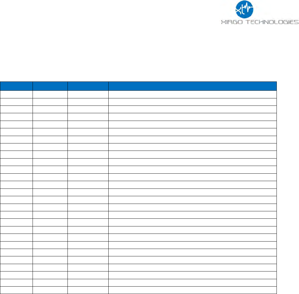
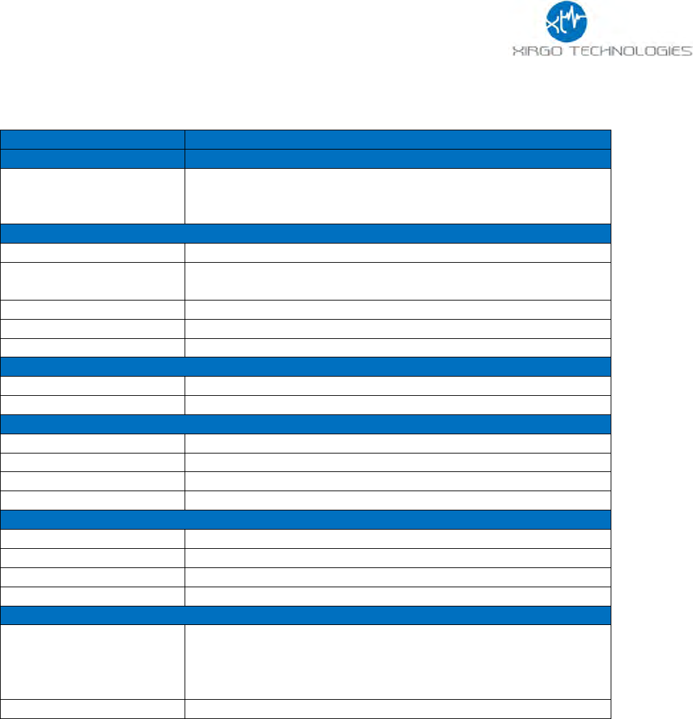
1.1 Feature Matrix
Feature Description
Base Unit
Zigbee®
Upgrade
3G Communication Module with 2G fallback
GPS Receiver for Tracking Applications
Supports SMS, TCP, UDP, FTP
Over-the-air Configuration and FW Upgrade
Location Polling
Periodic Reporting
Wired or Virtual Ignition On/Off Reporting
Direction Change Alerts
Speed Threshold Alerts
Mileage Threshold Alerts
Main Battery Disconnect Alerts
Heartbeat and Power-up/Reset Alerts
Ignition Idle Alert (wired ignition only)
Towing Start/Stop Alerts(wired ignition only)
Movement Start/Stop Alerts (wired ignition only)
2 Digital Inputs
Park Time Alerts (wired ignition only)
Virtual Odometer
Motion
Sleep/Wake Configuration Settings
Geofence (Radial, Rectangular, and Polygonal)
Device Diagnostics (Battery voltage, connectivity, etc.)
Wireless Sensor Connectivity
Inter-device Communication
6
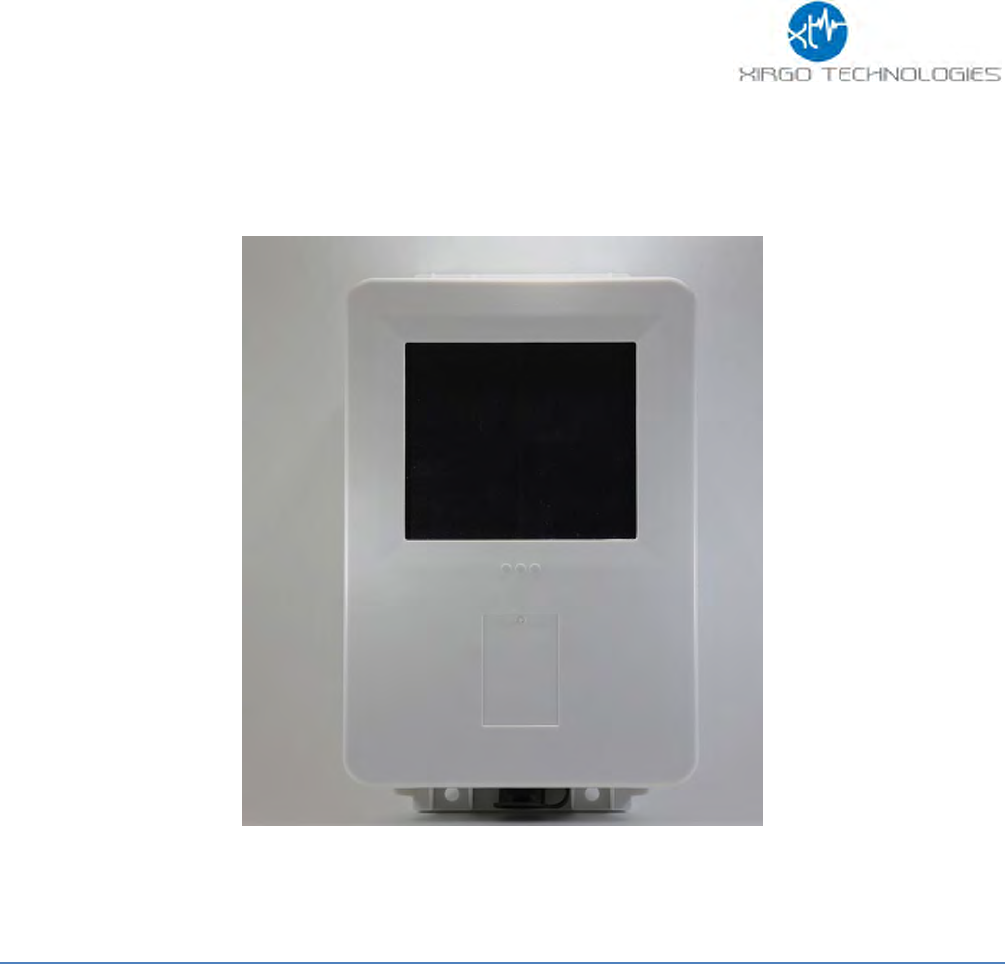
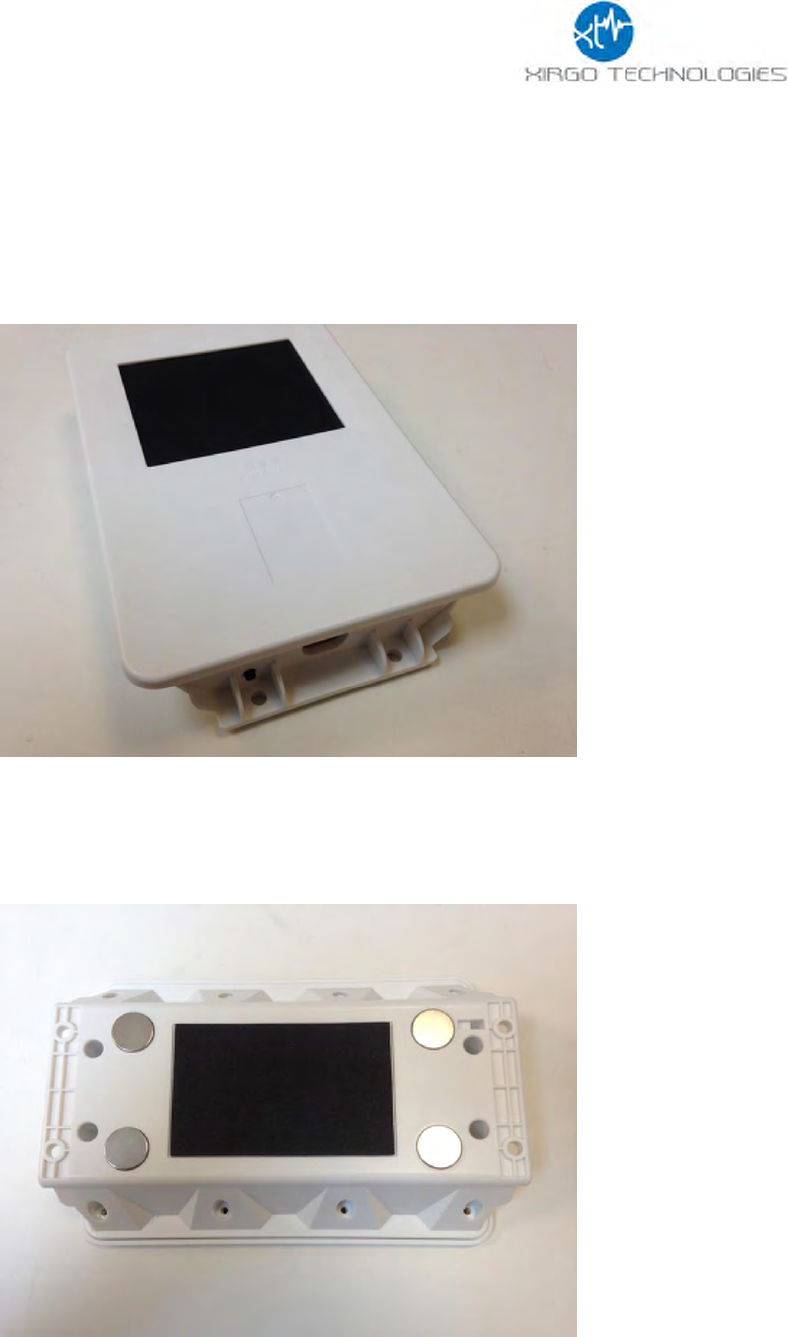
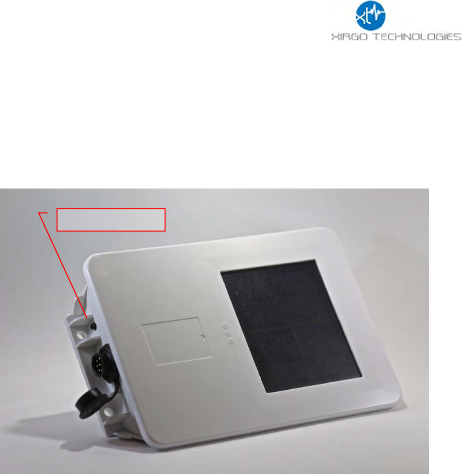
2 Hardware Description
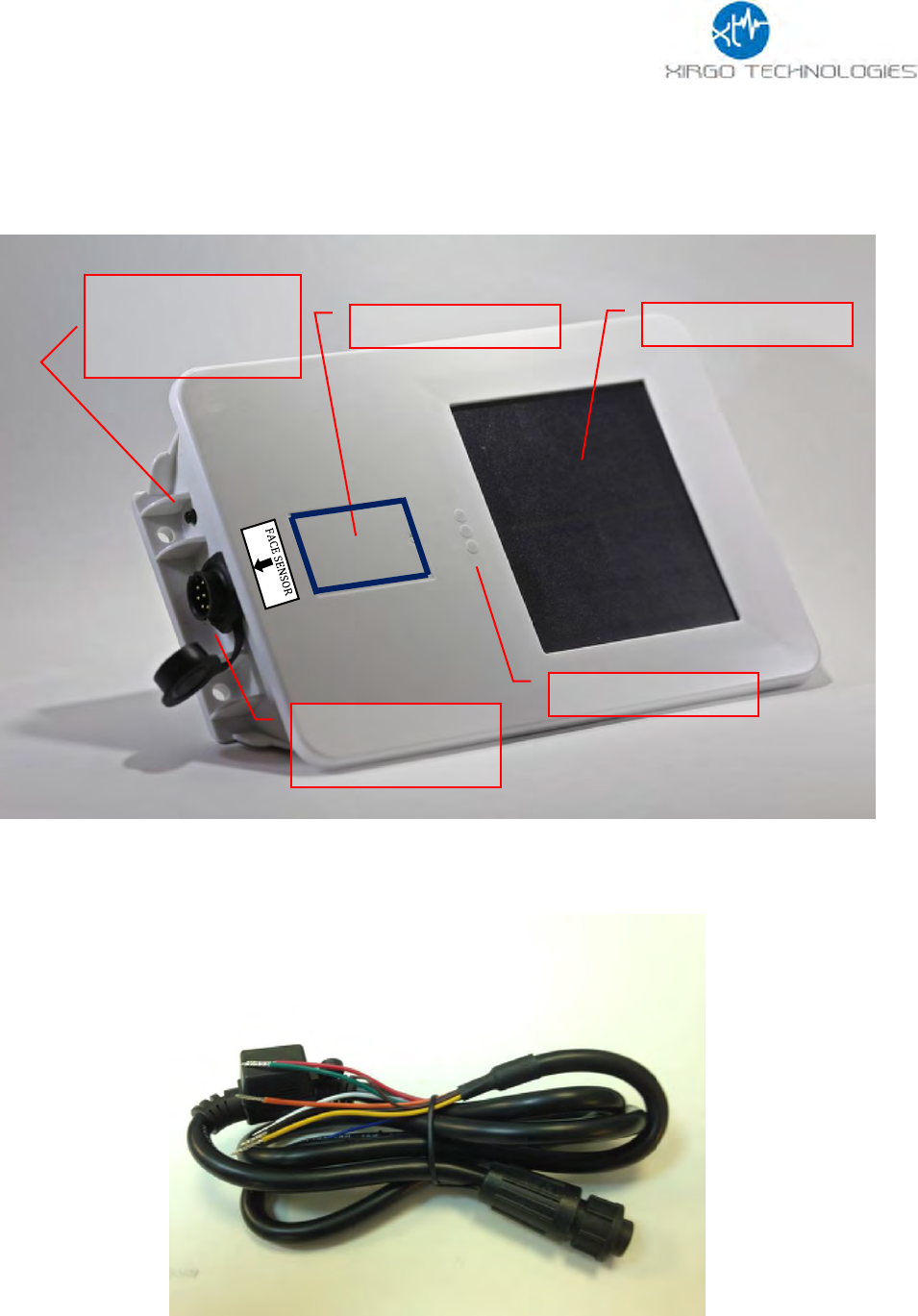
Below is a depiction of key interfaces of the XT-4860G2:
The Associated Cable Harness that interfaces with the unit is shown below:
Solar Panel
LED Indicators
Device Label
Wake-up/
Zigbee Pairing
Button
Zigb
7-Pin Bayonet
Connector
7
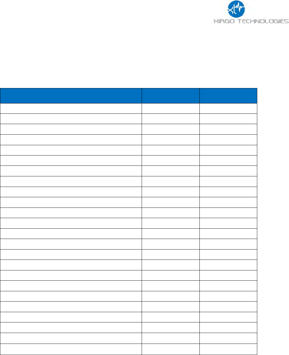
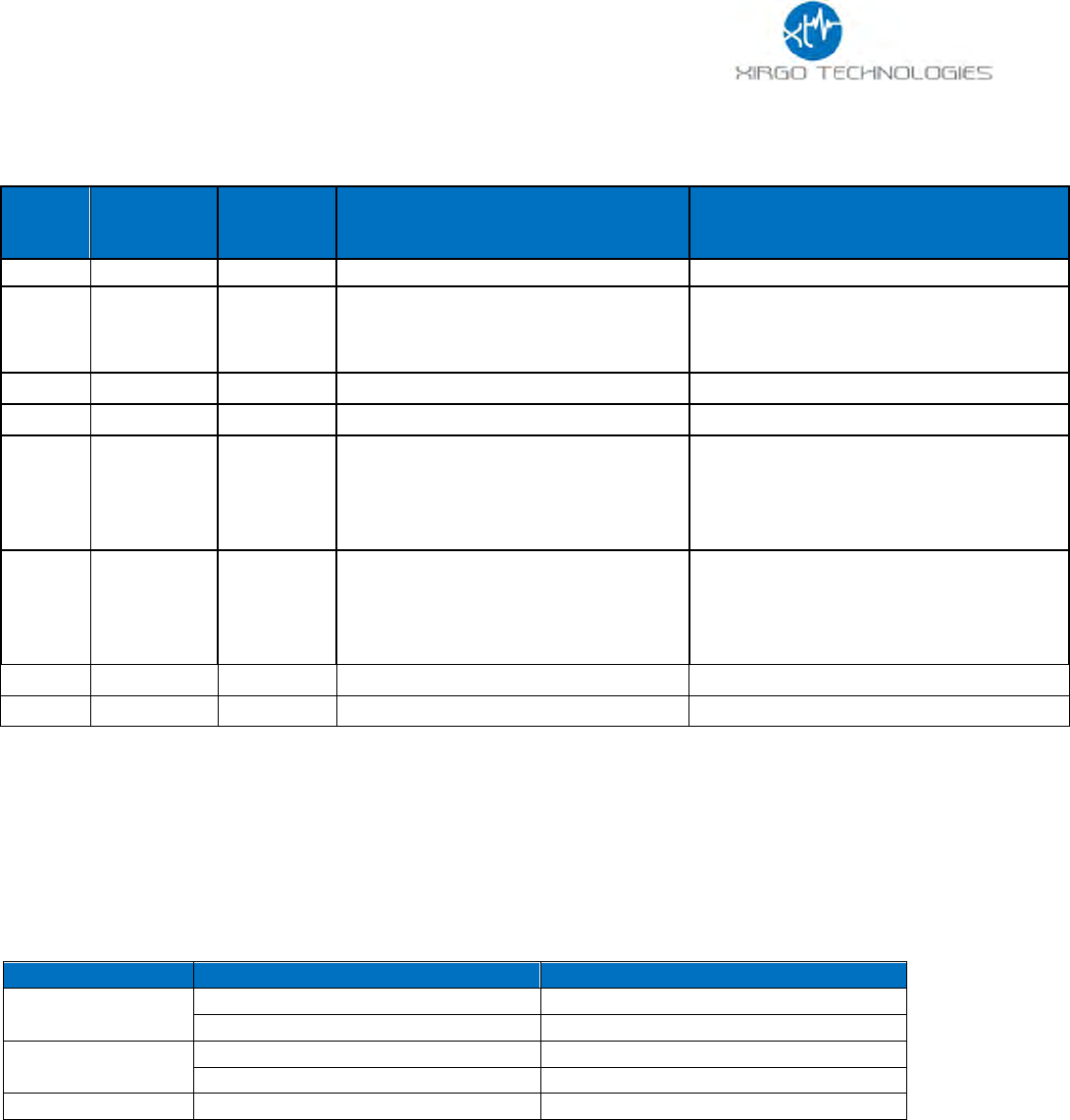
2.1 Hardware Specifications
Technology
3G UMTS/HSDPA/HSUPA
Model
XT-4860G2
Frequency Band
Dual-band Support
Band II – 1900 MHz
Band V – 850 MHz
GPS Specification
Receiver 50 channels
50 channels
Receiver tracking
Sensitivity
-161 dBm
Accuracy
+/- 2.5m CEP (50% , -130 dBm, > 6 Satellites)
Cold Start
<33 sec
Hot Start
< 1 sec
Power Requirements
D.C. Power
8-24V, 12 V nominal
Battery
Internal 6600mAh rechargeable Li-Ion
Physical Connection
Interface Connector
8-pin attached harness
Cellular/GPS Antenna
Internal
SIM Access
Internal
Programming
Serial (UART Logic Level)
Mechanical
Case Material
ABS plastic with weather-proofing for outdoor use
Dimension
7.6” X 4.9” X 1.4”
Weight
< 18 oz. (Estimated)
Operating Temperature
-30°C to +70°C
Certifications
Product
PTCRB
ATT
IC
IP67
Carrier
AT&T
8
2.2 Cable Harness Description
Pin #
Wire
Color
Pin Name
Functional Description
Port Characteristic
1
White
IN1
Ignition Sense
8v to 24v, Internally pulled low
2
Yellow
IN2
Input port
2.4 to 24V, < 0.2 V
Note: Internally pulled high
3
Black
Ground
Ground
4
Green
Out
Output Port (Defaulted open
circuit)
5
Blue
UART-Rx
External battery negative terminal
3.3V Logic Interface
Com Port Settings:
Baud rate: 115200 bps; Flow control:
None; 8N1
6
Brown
UART-Tx
3.3V Logic Interface
Com Port Settings:
Baud rate: 115200 bps; Flow control:
None;8N1
7
Red
VBATT
Main battery voltage, DC
8-24 V
8
Orange
ADC
Analog Input
8-24 V
2.3 LED Description
LED
Description
Status
Cellular (Blue)
Searching for Cellular Network
LED OFF
Cellular Carrier Lock
Fast Blinking once every 1 second
GPS (Green)
Searching for satellite
Solid
GPS Lock
Blinking
Zigbee (Aurburn)
TBD
TBD
9
3 Device Mounting Options
3.1 Screw Mounting
The XT-4860G2 has two flanges (two holes per) at each end of the housing for screw mounting
the device to the mounting surface.
3.2 Magnetic Mounting
The XT-4860G2 can also be equipped with magnets which support a load up to 10kg.
10
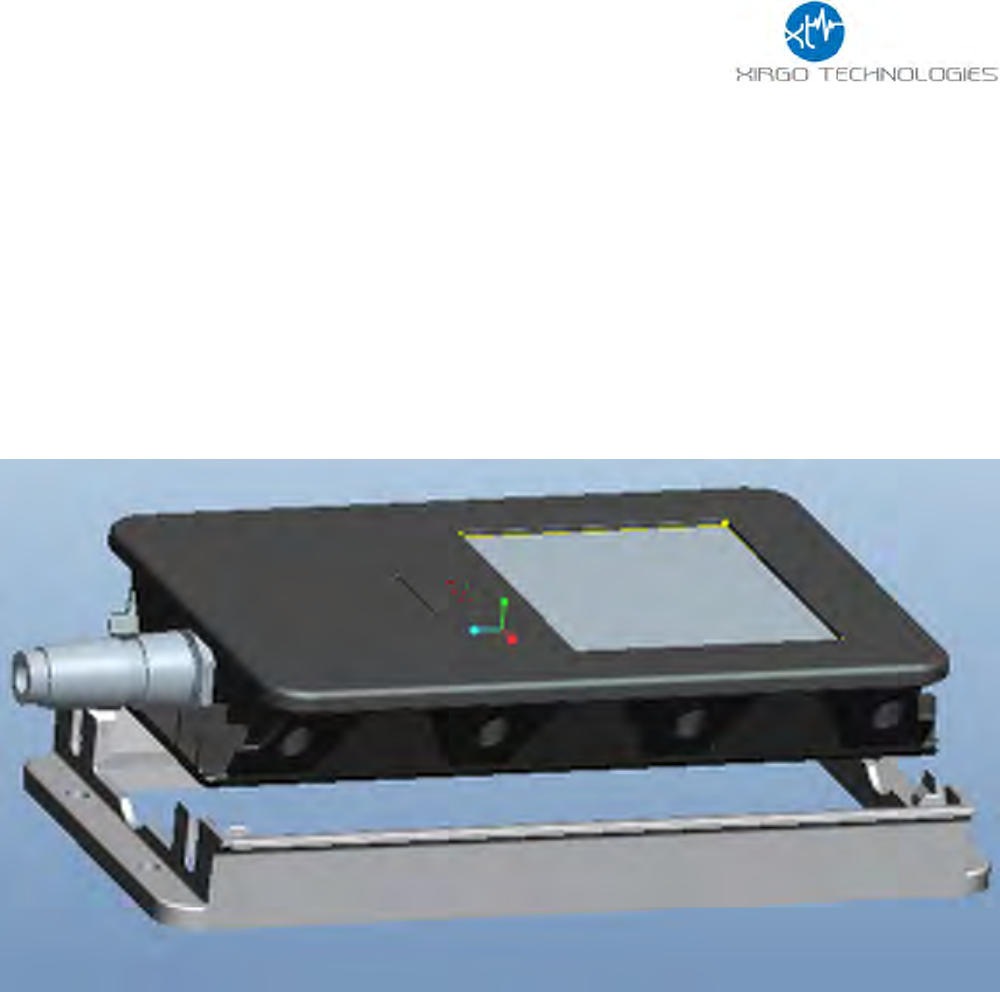
3.3 Optional Cradle Mounting
An optional mounting cradle can be purchased for easy snap-on/snap-off device mounting for the
XT-4860G2. The cradle will need to be screw-mounted on to the position desired.
11
4 Quick Start Guide
4.1 Device Wakeup
To start up the device, simply hold the black button located near the circular connector on the
side panel of the device for 3 seconds. You should see the blue “C” LED light up and then fade out.
The LED will fast-blink when the device is successfully connected to the network.
Wake up Button

12
4.2 Configuring the Device via SMS
1) Ensure your device is active on your cellular account.
2) Awaken device from sleep XT-4860G2 via the “wake-up” button.
3) If the device needs more power, then supply 12V DC via the red wire of the cable harness.
4) Ensure device cellular LED is blinking based on LED definition in this document.
5) Using your mobile phone or SMS gateway send +XT:1008 command to the device MDN
6) Command: “+XT:1008,<SM>”- Sets SMS Number
7) Response (via SMS): $$<UID>,<1008>,<SM>##
8) Once you have set SMS to reply to your mobile or gateway, you can now send other
commands to device via SMS per device protocol documentation.
a. Command +XT:1010 configures network settings
b. Command +XT:3040 and +XT:3042 configure alert and threshold settings
9) +XT:7008 save device configuration to permanent memory

13
FCC/IC:
REGULATORY COMPLIANCE INFORMATION
This equipment with FCC-ID: GKM-XT4820 and IC-ID: 10281A-XT-4820, Model: XT-4860G2
is subject to the Federal Communications Commission (FCC) and Industry Canada (IC) rules.
NOTICE:
Changes or modifications not expressly approved by the party responsible for compliance could void the user's
authority to operate the equipment.
This device complies with Part 15 of the FCC Rules and with license exempt Radio Standard Specifications of
Industry Canada.
Operation is subject to the following two conditions:
(1) this device may not cause harmful interference, and
(2) this device must accept any interference received, including interference that may cause undesired
operation.
Les changements ou modifications non expressément approuvés par la partie responsable de la conformité
pourraient annuler l'autorité de l'utilisateur à utiliser l'équipement.
Le présent appareil est conforme aux CNR d'Industrie Canada applicables aux appareils radio exempts de
licence. L'exploitation est autorisée aux deux conditions suivantes :
(1) l'appareil ne doit pas produire de brouillage, et
(2) l'utilisateur de l'appareil doit accepter tout brouillage radioélectrique subi, même si le brouillage est
susceptible d'en compromettre le onctionnemen
Radio frequency radiation exposure Information:
This equipment complies with FCC radiation exposure limits set forth for an uncontrolled
environment. This equipment should be installed and operated with minimum distance of 20 cm
between the radiator and your body. This transmitter must not be co-located or operating in
conjunction with any other antenna or transmitter.