Xmark DLAR Low Power Receiver User Manual c temp lar prn
Xmark Corporation Low Power Receiver c temp lar prn
Xmark >
Installation guide
ReferenceDocuments
LimitationofLiability
Warnings
Warranty
•PerceptIsInstallationManual(p/n805I0301)
•HugsSystemManual(p/n805U1601)
•PerceptIsSystemManual(p/n805U0601)
Instantelherebydisclaimsallwarranties,expressorimplied,arising
outoforinconnectionwithanyofitsProductsoftheuseor
performancethereof,includingbutnotlimitedto,whereallowable
bylaw,allotherimpliedwarrantiesorconditionsofmerchantable
qualityandfitnessforaparticularpurposeandthosearisingby
statuteorotherwiseinlaworfromacourseofdealingorusageof
trade.
Instantel'sproductsarewarrantedagainstdefectsinmaterialsand
workmanshipandshallperforminaccordancewithpublished
specificationsforaperiodofoneyear.InstantelInc.reservesthe
righttochangespecificationswithoutnotice.
ThisProducthasbeendesignedforuseto:a)assistpersonnelin
summoninghelpwhentheyareunderpersonalduress,b)assistin
thepreventionofinfantabductionc)locateassets,d)assistinthe
preventionofthelossofassetsand/ore)toreducetheriskof
residentwanderingthroughremotedetection.
Therange,accuracy,functionandperformanceofthisProduct
mayvaryfromthepublishedspecificationsduetomanyfactors,
including,withoutlimitation,siteimpairmentsfromstructural
effects,metalobjectsinthevicinity,placementofthereceiverand
transmitter,interferencefromotherelectricaldevices,atmospheric
effects,installation,andmaintenance.Theremaybeotherfactors
whichalsoaffectperformanceofthisProduct.Instanteldoesnot
guaranteethatthisProductwill:a)detect100%ofthecallsfor
personalassistance,b)detect100%ofinfantabductions,c)locate
allassets100%ofthetime,d)preventthelossofassets,and/ore)
detect100%ofresidentwanderingnordoesInstantelguarantee
thatthisProductwillnotreturnfalsereportsofresident
wandering.
MonthlytestingandmaintenanceofthisProduct,asdescribedin
theProductdocumentation,isessentialtoverifythesystemis
operatingcorrectlyandtoensurethattheprobabilityofdetecting
analarmandlocatingthetagaremaximized.Thefailureto
undertakeregulartestingandmaintenancewillincreasetheriskof
systemfailureand:a)failuretoreportpersonalduresscalls,b)
failuretolocateassets, c)failuretopreventthelossofassets.
•NoUserAdjustments-therearenouseradjustments.
Tamperingwiththeinternalcircuitrymaycausecomponentor
systemfailure,orboth,andwillvoidthewarranty.
•Donottouchorotherwisehandletheinternalcomponents;
doingsoshallvoidthewarranty.
Instantel'sliabilitytoyouoranyoneclaimingthroughoronbehalf
ofyouwithrespecttoanyclaimorlossarisingoutoftheuseor
misuseof
Note:Thisequipmenthasbeentestedandfoundtocomplywith
thelimitsforaClassBdigitaldevice,pursuanttopart15ofthe
FCCRules.Theselimitsaredesignedtoprovidereasonable
protectionagainstharmfulinterferenceinaresidentialinstallation.
Thisequipmentgenerates,usesandcanradiateradiofrequency
energyand,ifnotinstalledandusedinaccordancewiththe
instructions,maycauseharmfulinterferencetoradio
communications.However,thereisnoguaranteethatinterference
willnotoccurinaparticularinstallation.Ifthisequipmentdoes
causeharmfulinterferencetoradioortelevisionreception,which
canbedeterminedbyturningtheequipmentoffandon,theuseris
encouragedtotrytocorrecttheinterferencebyoneormoreofthe
followingmeasures:
·Reorientorrelocatethereceivingantenna.
·Increasetheseparationbetweentheequipmentandreceiver.
·Connecttheequipmentintoanoutletonacircuitdifferentfrom
thattowhichthereceiverisconnected.
Consultthedealeroranexperiencedradio/TVtechnicianforhelp.
ThisdevicecomplieswithRSS-210ofIndustryandScienceCanada.
Operationissubjecttothefollowingtwoconditions:(1)thisdevice
maynotcauseinterference,and(2)thisdevicemustacceptany
interference,includinginterferencethatmaycauseundesired
operationofthedevice.
Instantel'sProduct,defectiveproductsormaterials,
improperinstallationormaintenanceofInstantel'sProductor
productsorthesysteminwhichtheyareincorporated,orallegedto
haveresultedfromanactoromissionofInstanteloranyperson,
negligentorotherwise,shallbelimitedto:
A)TherepairorreplacementofdefectiveProductormaterials
suppliedbyInstantelduringthewarrantyperiodassetoutin
theProductdocumentation;or,
B)AttheoptionofInstantel,refundofthepurchasepriceofthe
ProductsuppliedbyInstantel.
InnoeventshallInstantelbeliableforgeneral,specific,indirect,
consequential,incidental,exemplaryorpunitivedamagesorany
lossesorexpensessufferedbyyouoranyoneelse,whetherornot
Instantel,oritsemployees,officers,agents,resellersorinstallershas
beeninformedoftheriskofsuchlossorexpenseandwhetheror
notsuchlossesorexpenseswereforeseeable.
UnitedStatesFCC
CanadaISC
Statements:
Tollfree800-267-9111(UnitedStatesandCanada)
or613-592-4642
613-592-4296
309LeggetDrive,Kanata,ON,Canada,K2K3A3
or826ProctorAvenue,Ogdensburg,
NY,U.S.A.,13669-2203
www.Instantel.com
Phone:
Fax:
Address:
Website:
©1998-2000InstantelInc.AllRightsReserved.Instantelandthe
InstantellogoareregisteredtrademarksofInstantelInc.inNorth
America.PerceptIs,thePerceptIslogo,MyCall,FindIt,Communicator
andHugsaretrademarksofInstantelInc.Otherbrandandproduct
namesaretrademarksorregisteredtrademarksoftheirrespective
holders.Aspartofourcontinuingcommitmenttoproductexcellence,
Instantelreservestherighttochangespecificationswithoutnotice.
PrintedinCanada,May2000.805U0501Rev04
Readthese
instructions
thoroughlybefore
installingtheLocal
AreaReceiver.
Faultyinstallation
canleadtosystem
failure.
!
INSTANTELLOCATINGTECHNOLOGIES
!
!
!
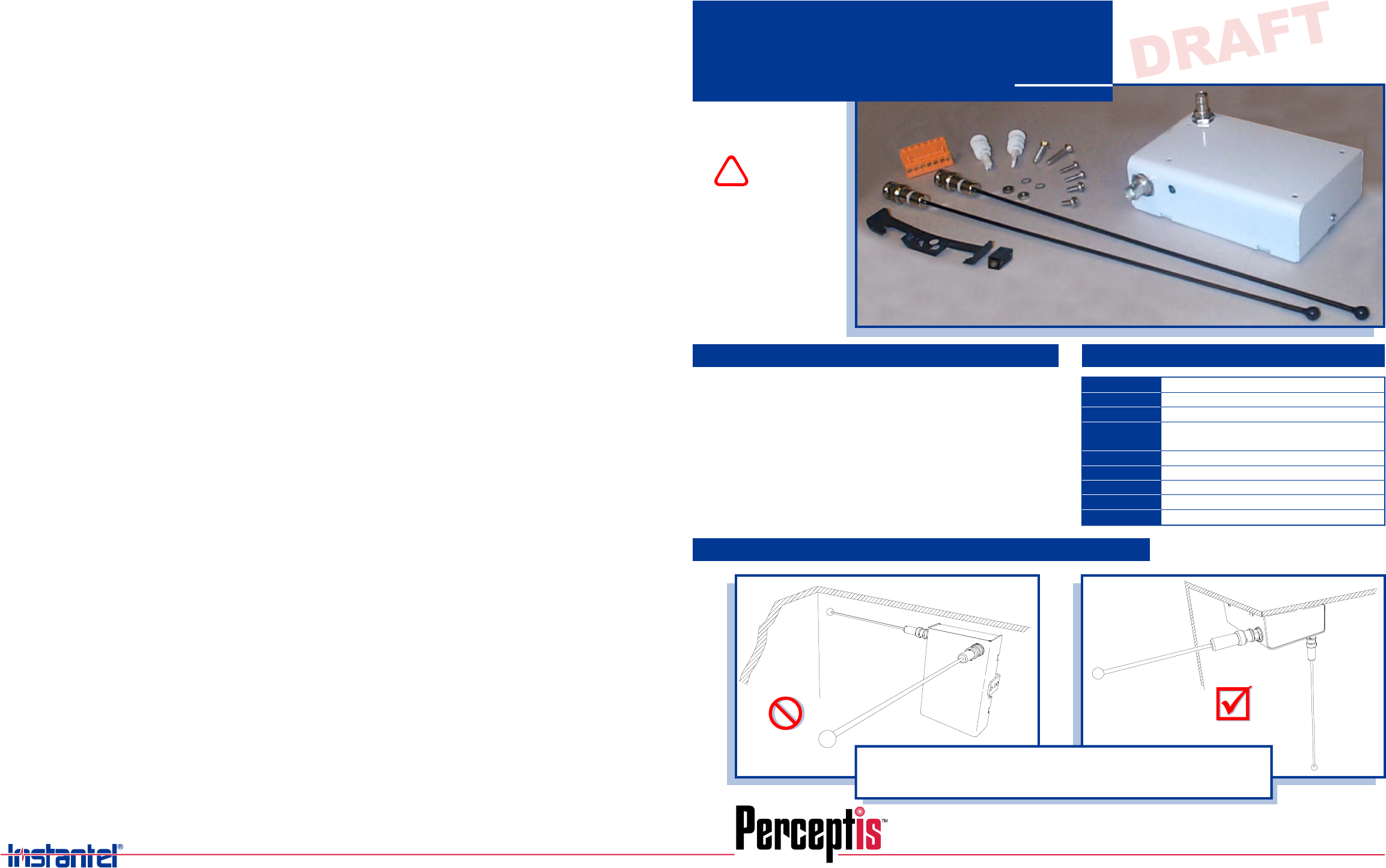
InstantelLocalAreaReceiver(p/n805A0501).
FacilityfloorplanindicatingLARpositions
andnetworkwiringpath.
NetworkTerminator105(p/n805A2401)
requiredtoterminatenetwork.Two
terminatorsareprovidedwitheach
ControllerPC(p/n805A2201)orLaptop
Controller(p/n805A2202).
Ω
LocalAreaReceiver
InstallationGuide
MATERIALS REQUIRED
LARORIENTATION
LARSPECIFICATIONS
•
•Theantennashaveaprotectivecoveringtopreventthemfromtouchingmetal.
EnsurethattheLARisatleast2'ft.frommetalobjects,suchasframingorairducts.
•Mainantennashouldbepointingdownwardintoanareafreeofmetalobstructions.
!
OnthePracticalEdgeofTechnology
217MHz
10to30VDC
60mA@12VDCor24VDC,100mAMaximum
50ft.(15meters)overlappingLARs
35ft.(11meters)stand-aloneLARs
Frequency
SupplyVoltage
CurrentDraw
DetectionRadius
Communications
Temperature
Humidity
Dimensions
Weight
LonWorks2wire
32°to122°F(0°to50°C)
0to90%RH@70°F(21°C),non-condensing
Approximately5.2x3.3x1.5in.(133x84x38mm)
Approximately9.2oz.(260g)
LocateandrecordtheLonWorksidentification
numberontothefacilityfloorplanindicatingthe
LAR'spositionandnetworkwiringpath.
PlugthewiredconnectorintotheLARand
installtheLARontotheMountingPlate,using
thescrewremovedinStep2.place
excessnetworkandpowersupplywiresinside
theLARcase.
DONOT
Installthetwoantennas.
Theantennashaveaprotectivecoveringtopreventthem
fromtouchingmetal.Ensurethattheydonottouch
metalobjects;donotencase,wrap,orotherwisecoverthe
antennaswithmetallicmaterials.
TurnPowerON. AddtheLARstothe
PerceptIssoftwareusingtheAutoConfigure
commandinthe
dialogbox.
AddLARiconstothefacilitymapsrepresenting
theLARs'actualphysicallocation.
LonWorksDeviceInstallation
Commissionthesystem.
Checkallsystemcomponents,andensurethat
thePerceptIssoftwaredisplaysallLARsand
receivesallalarmsfromeachLAR.CheckLAR
coverage;seetheCommissioningchapterinthe
PerceptIsInstallationManual(p/n805I0301)for
furtherinstructions.
PriortoinstallingtheLAR,ensurethatthe
PowerSupplyisTURNEDOFFtoprevent
electricalshockordamagetoequipment.
DONOTturnonthePowerSupplyuntilall
devicesareinstalled.Afterthesystemis
installed,completethefollowingsteps.
RemovetheMountingPlatefromtheLAR.
AttachtheSplitFerriteCoretothe
powersupplywire,passingthewirethroughthe
corethreetimes.Leaveenoughwirelengthso
thattheferritecoreis1/2inchfromtheoutside
oftheLARcase,asshownin
IftheLARistobeinstalledtoareceptaclebox,
passthenetworkandpowersupplywires
throughtheholeintheMountingPlate.
Otherwise,wiretheconnectorasshown,andput
thewiresthroughtheslotprovidedontheside
oftheLARcaseinStep4.
ConnecttheLonWorksNetworkIN,Network
OUT,andPowerSupplytotheterminals,as
shownin.IftheLARisattheendof
thenetwork,thenterminatethenetwork
segmentwith(105terminator).
(ItemA)
DetailA.
DetailA
ItemB Ω
Referringtothefacilityfloorplan,positionthe
LARMountingPlate.Donotplacenearmetal
objectsandstructuralframes.Ensurethatthe
statusLEDwillbevisibleandthatspaceis
allowedfortheantennas.InstalltheLAR
MountingPlateusingoneofthefollowing
methods.
Fastentoasuspendedceilingguywire,
using:
1-Caddy,multi-functionclip
2-Screws,machine
2-Nuts,hex
Installwiththe-bracketontheMounting
Plate,orwiththetwoholesprovided
forattachmenttoareceptaclebox,
using:
A)
B) L
2-Screws,wood
2-Hollowwallanchors
InstalltheLARtoanexistingreceptaclebox,
using:
2-Screws,machine
2-Nuts,hex.
C)
OnthePracticalEdgeofTechnology
!
!
STEP STEP
DESCRIPTION DESCRIPTION
Donotencase,wrap,
orotherwisecoverthe
antennaswithmetallic
materials.
TwoNeuronI.D.labelsare
supplied;placeonelabelon
theLARinavisiblelocation,
andthesecondlabelonthe
facilitymapinthe
correspondinginstalled
position.
Theantennashavea
protectivecoveringto
preventthemfrom
touchingmetal.
EnsurethattheLARis
atleast2ft.frommetal
objects,suchas
framingorairducts.
2X
OR
NOTE:
OR
ServiceLight
OFF
Flashingevery
0.5seconds.
ON
NormalOperation.
UnconfiguredLAR.
Requiresconfigurationusing
thePerceptIssoftware.
Trouble.HardwareFailure.Download
newOSsoftwaretotheLAR.Seethe
LARinstallationsectionofthePerceptIs
InstallationManual.
NETWORK
IN POWER
NEG-POS+
NETWORK
OUT
DETAILA
!
ITEMB
(ateachend
ofnetwork)
ITEMA
(passwire
through
thecore
3times)
1/2"
Figure1-LocalAreaReceiverInstallation
Installation
Guide
3C
3A
3B