Xmark R2R SUPERHETERODYNE RECEIVER User Manual Protocol
Xmark Corporation SUPERHETERODYNE RECEIVER Protocol
Xmark >
Contents
- 1. Communication Protocol manual
- 2. Installation manual
- 3. User manual
Communication Protocol manual

“Halo” System
Communication Protocol
Revision 0.1
July 27, 1999
970-00002-000

“Halo” System: Communication Protocol 970-00002-000
EXI Wireless Systems, Confidential Page 2 of 33 July 27, 1999
Revisions
Version Date Changed by Description
0.1 6/29/99 Dalibor Pokrajac Initial Release

“Halo” System: Communication Protocol 970-00002-000
EXI Wireless Systems, Confidential Page 3 of 33 July 27, 1999
Approvals
COO ______________________________________ Date: ___________________
Engineering ______________________________________ Date: ___________________
Manufacturing ______________________________________ Date: ___________________
Quality ______________________________________ Date: ___________________
Purchasing ______________________________________ Date: ___________________

“Halo” System: Communication Protocol 970-00002-000
EXI Wireless Systems, Confidential Page 4 of 33 July 27, 1999
1. Document Purpose.......................................................................................................... 6
2. Introduction..................................................................................................................... 7
3. System Architecture......................................................................................................... 8
3.1. Host..............................................................................................................................8
3.2. Data Gathering and Control Nodes...........................................................................8
3.2.1. Controller...................................................................................................................................... 9
3.2.2. Elevator......................................................................................................................................... 9
3.2.3. Receiver......................................................................................................................................... 9
3.3. Sensors.........................................................................................................................9
3.4. Communication...........................................................................................................9
3.4.1. RF Communication....................................................................................................................10
3.4.2. Weigand Communication...........................................................................................................10
3.4.3. Control Lines Communication ..................................................................................................10
3.4.4. EIA-485 Communication...........................................................................................................10
4. RF Communication Protocol.......................................................................................11
4.1. Tag in the Field (TIF Alarm)....................................................................................11
4.1.1. Field of coverage ........................................................................................................................11
4.1.2. Bit By Bit Interrogation..............................................................................................................12
4.1.3. Respond Command.....................................................................................................................13
4.1.4. Reset Command..........................................................................................................................14
4.2. Tag Initiated Communication (TIC alarm) .............................................................14
4.2.1. Message format...........................................................................................................................15
ID number format........................................................................................................................................16
5. Weigand Communication Protocol.............................................................................17
5.1. General ......................................................................................................................17
5.2. Weigand Messages....................................................................................................17
5.2.1. Parity Bits (Even and Odd).........................................................................................................18
5.2.2. Control Code...............................................................................................................................19
5.2.2.1. Normal................................................................................................................................19
5.2.2.2. Bypassed..............................................................................................................................19
5.2.2.3. TIF Alarm............................................................................................................................19
5.2.2.4. Loiter...................................................................................................................................19
5.2.2.5. Host Alarm ON...................................................................................................................20
5.2.2.6. Unlock Request ON ...........................................................................................................20
5.2.2.7. TIC Alarm...........................................................................................................................20
5.2.2.8. Test Mode ...........................................................................................................................20
5.2.2.9. Pin Number Entry...............................................................................................................20
5.2.2.10. Event (Door Open).............................................................................................................20
5.2.2.11. Switch Configuration.........................................................................................................20
5.2.2.12. Status...................................................................................................................................22
6. Signal lines communication.........................................................................................24
7. EIA-485 Communication.............................................................................................26
7.1. General ......................................................................................................................26

“Halo” System: Communication Protocol 970-00002-000
EXI Wireless Systems, Confidential Page 5 of 33 July 27, 1999
7.2. Network performance ..............................................................................................26
7.3. Communication parameters.....................................................................................27
7.4. Message format.........................................................................................................27
7.5. Message Structure....................................................................................................28
7.5.1. Assign Network address .............................................................................................................28
7.5.2. Test Node Presence.....................................................................................................................29
7.5.3. Node Present...............................................................................................................................29
7.5.4. Send / Request Data....................................................................................................................29
7.5.5. Device Data.................................................................................................................................30
8. Glossary..........................................................................................................................32
9. References......................................................................................................................33

“Halo” System: Communication Protocol 970-00002-000
EXI Wireless Systems, Confidential Page 6 of 33 July 27, 1999
1. Document Purpose
This document describes a communication protocol used by “HALO” system.
This document is written after the system design has been finished and the objective is to describe structure
of the system protocol, not only to people directly involved in the software and firmware design but to
other technical personnel as well, involved in other aspects of system design, installation or technical
support.

“Halo” System: Communication Protocol 970-00002-000
EXI Wireless Systems, Confidential Page 7 of 33 July 27, 1999
2. Introduction
“Hallo” system is specialized data gathering and control system which is using different communication
media and protocols to achieve its tasks. The system consists of several major building blocks – Host,
Controllers (Elevators, Receivers) and Tags.
Data that are gathered are information sent by the Tags.
The system can be used in different applications and some of them include:
• Patient monitoring (P-Tag)
This is primary application for the “Hallo” system. It can be used in the hospitals to prevent babies
abduction or to restrict movement for certain groups of patients that need to be monitored (e.g. Alzheimer
patients).
• Asset monitoring (A-Tag)
The “ Hallo” system can be used to prevent or warn of any unauthorized assets relocation (e.g. a notebook
computer which shouldn’t leave the room or the building).
• Distress monitoring (D-Tag)
In this application D-Tags are used to signal some abnormal situation and they are activated by person who
is carrying it. (e.g. a nurse threatened by a violent patient)
Each one of these Tags is using the same protocol and has virtually the same functionality within the
system. The difference is in peripheral sensing circuitry which will determine how are they activated. In
order to simplify this protocol description, all of them will be referred to just as Tags.
“Halo” System: Communication Protocol 970-00002-000
EXI Wireless Systems, Confidential Page 8 of 33 July 27, 1999
3. System Architecture
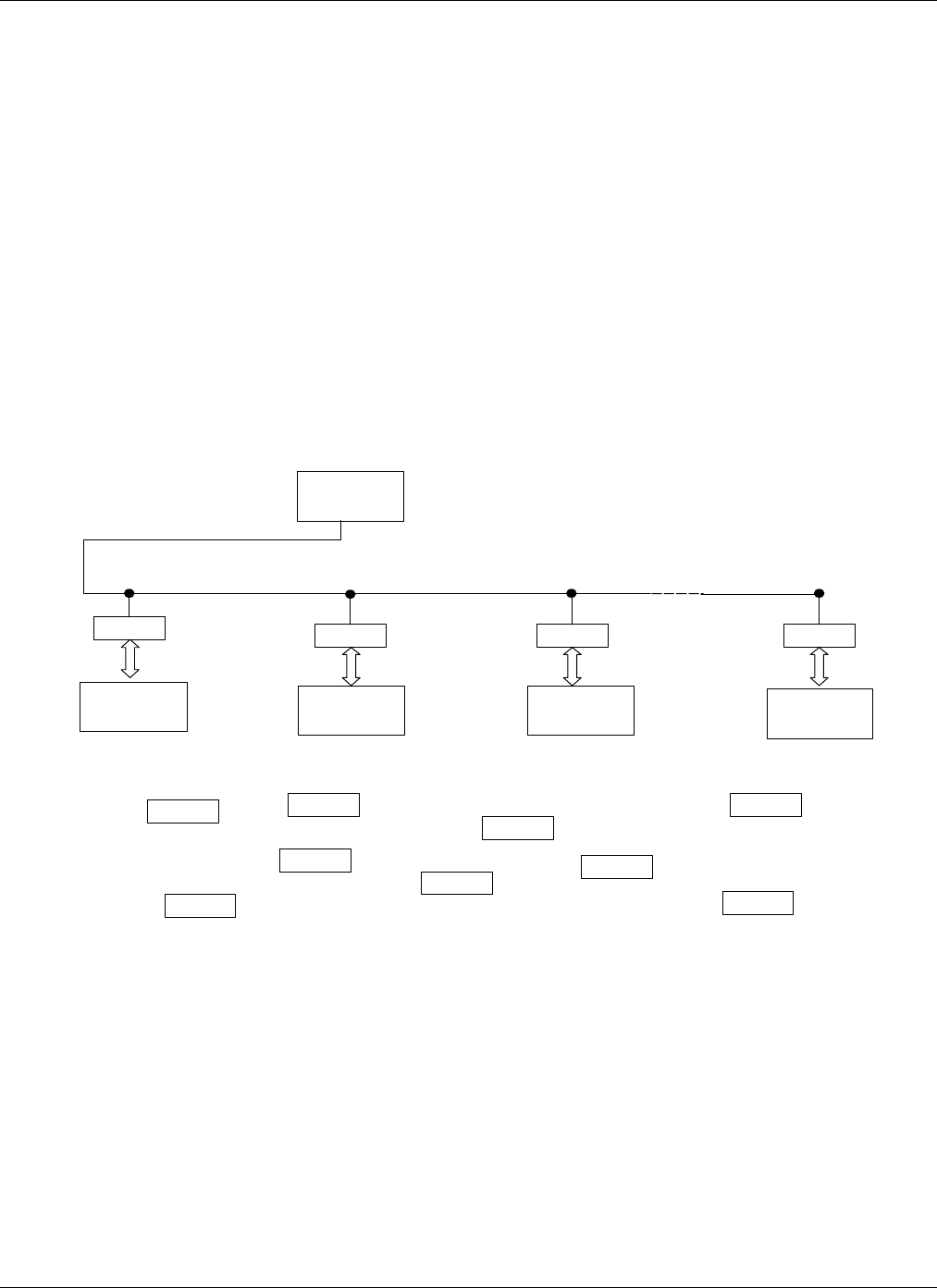
The “Hallo’ system can be classified into the group of data gathering and control systems and its
components could be divided into 3 major groups:
• Host (Computer)
• Data gathering and control nodes (Controllers, Elevators, Receivers, Printer Interface, Programmers)
• Sensors (P-Tag, A-Tag, D-Tag)
Figure 1 shows how these units are organized within the system.
3.1. Host
The Host is Windows based User Interface running on a PC. It serves as a terminal from which the user can
monitor the system operation and exercise available controls. There can be only one Host and it is acting as
a Master device within the system. The Host must be equipped with the EIA-485 / EIA-232 converter in
order to be able to communicate to the rest of the system.
3.2. Data Gathering and Control Nodes
There are 3 types of the nodes in this group and they vary in their functionality, but one feature is common
among all of them; they are all able to communicate to the Tags and to the Host. These are two completely
different communication paths and will be examined in details in this document
Figure 1
Controller Elevator
Host PC
RIM
RIM
RIM
Receiver
RIM
Receiver
Tag
Tag
Tag
Tag
Tag
Tag
Tag
Tag
Tag

“Halo” System: Communication Protocol 970-00002-000
EXI Wireless Systems, Confidential Page 9 of 33 July 27, 1999
3.2.1. Controller
The Controller is used to monitor and control the area in which it is installed, usually near the door. It
generates the “field of coverage” around itself and any Tag entering this field will be registered by the
Controller (Tag In the Field (TIF) alarm). The other Controller’s task is to register if any of the Tags are
sending TIC alarm. When the Tag enters this mode depends on particular type of the Tag, but the
communication principle is always the same.
These alarms are passed to the Host via “RS-485 Interface Module” (RIM) which serves as an interface to
the RS-485 based network.
The Controller can be programmed to respond or not to a particular Tag, and when it does respond it can
take certain actions; lock / unlock the door, activate audible alarm and control any external device via the
relay.
3.2.2. Elevator
The Elevator node is special version of the Controller node. While the Controller is intended to cover the
area near the door, the elevator application has to be approached differently to avoid false alarm triggering
due to somebody just walking near the elevator and to avoid installing separate Controller on the every
floor, just to mention two most important reasons.
The Elevator communication to the Host is almost identical to the Controller.
3.2.3. Receiver
The Receiver is a node which will respond to TIC alarms only. It has limited control functionality (one
relay) and it can not receive any commands from the Host. The idea behind the Receiver concept is to
blanket the building with low cost nodes in order to reliably register TIC alarm. The Controllers could be
used for this purpose but they are not cost effective.
The Receiver communicates with the Host in similar fashion as the Controller but with limited
functionality.
3.3. Sensors
Tags are the only sensors in this system (if we disregard door open / closed sensing by a Controller and an
Elevator). There could be different types of tags within the system as discussed earlier, but all of them have
common characteristic to be able to communicate to the Controllers, Elevators or Receivers by using
common protocol.
3.4. Communication
There are 4 different communication protocols used in this system and the difference among them is
determined mostly by communication media used.
Figure 2
HOST TAGCONTROLLERRIM
485 Comm
Control Lines
Comm
Weigand
Comm
RF Comm

“Halo” System: Communication Protocol 970-00002-000
EXI Wireless Systems, Confidential Page 10 of 33 July 27, 1999
3.4.1. RF Communication
RF communication is taking place between Controllers, Elevators, Receivers on the one side an the Tags
on the other. This is two-way communication accomplished on 433.92 MHz in one direction and 307 kHz
in the other.
3.4.2. Weigand Communication
Weigand protocol is used between Controllers, Elevators, Receivers and corresponding RIMs. This is
unidirectional, 2-wire protocol and each line is used to transfer either ‘ones’ or ‘zeros’.
3.4.3. Control Lines Communication
This is again unidirectional protocol. Four lines are used to send information from the RIM to the
Controller, and they can be configured as either individual control lines or to form control code to transfer
different commands to the Controller
3.4.4. EIA-485 Communication
Controllers, Elevators and Receivers can not directly communicate to the Host. They need interface which
enables them to join the network. This interface is RIM and it converts Weigand protocol to the EIA-485
(in one direction, and EIA-485 protocol into Control Lines protocol in the other direction).
This is multidrop differential protocol which supports up to 256 nodes on the bus. The nodes are
communicating over a twisted pair cable and they should be distributed following the bus topology (EIA-
485 standard). The communication speed can be set to 3 different baud rates, 9600, 19200 or 57600 baud,
but this has to be set in the factory prior the system is shipped to the customer. Default baud rate setting is
57600 baud.
Some specifications of this protocol and comparison to the EIA 232 protocol is presented in Table 1.
Table 1
RS232 RS485
Cabling single ended multi-drop
Number of Devices 1 transmit
1 receive 256 transmitters
256 receivers
Communication Mode full duplex Half duplex
Max. Distance 50 feet at 19.2 Kbps 4000 feet at 100 Kbps
Max. Data Rate 19.2 Kbps for 50 feet 10 Mpbs for 50 feet
Signaling unbalanced Balanced
Mark (data 1) -5 V min.
-15 V max. 1.5 V min. (B>A)
5 V max. (B>A)
Space (data 0) 5 V min.
15 V max. 1.5 V min. (A>B)
5 V max. (A>B)
Input Level Min. +/- 3 V 0.2 V difference

“Halo” System: Communication Protocol 970-00002-000
EXI Wireless Systems, Confidential Page 11 of 33 July 27, 1999
4. RF Communication Protocol
All communication between the Tags and the Controllers is taking place across RF communication media.
Two frequencies are used:433.92 MHz and 307 kHz.
• 433.92 MHz Communication
This is a frequency which is used to transfer information from the Tag to the Controller. The guaranteed
range is 30 feet.
• 307 kHz Communication
This is a “field of coverage” which is modulated in order to send information from the Controller to the
Tag. The range of this field depends on a particular application and is usually set by the installer but it can
not exceed 10 feet.
There are two types of information that need to be transferred from the Tag to the Controller, “Tag in the
Field” (TIF) alarm and “Tag Initiated Communication” (TIC) alarm. These two alarms are actually the
essence of the whole “Halo” system.
4.1. Tag in the Field (TIF Alarm)
The Controller needs to know when any Tag enters the “field of coverage”. This information is then used to
take certain action or not, depending on the system setup.
4.1.1. Field of coverage
The Controller generates the “field of coverage” around itself continuously. It is transmitting “wakeup
word” every 100 ms and waits for the response from any potential Tags that could enter this field or the
Tags already in the field previously “named”.
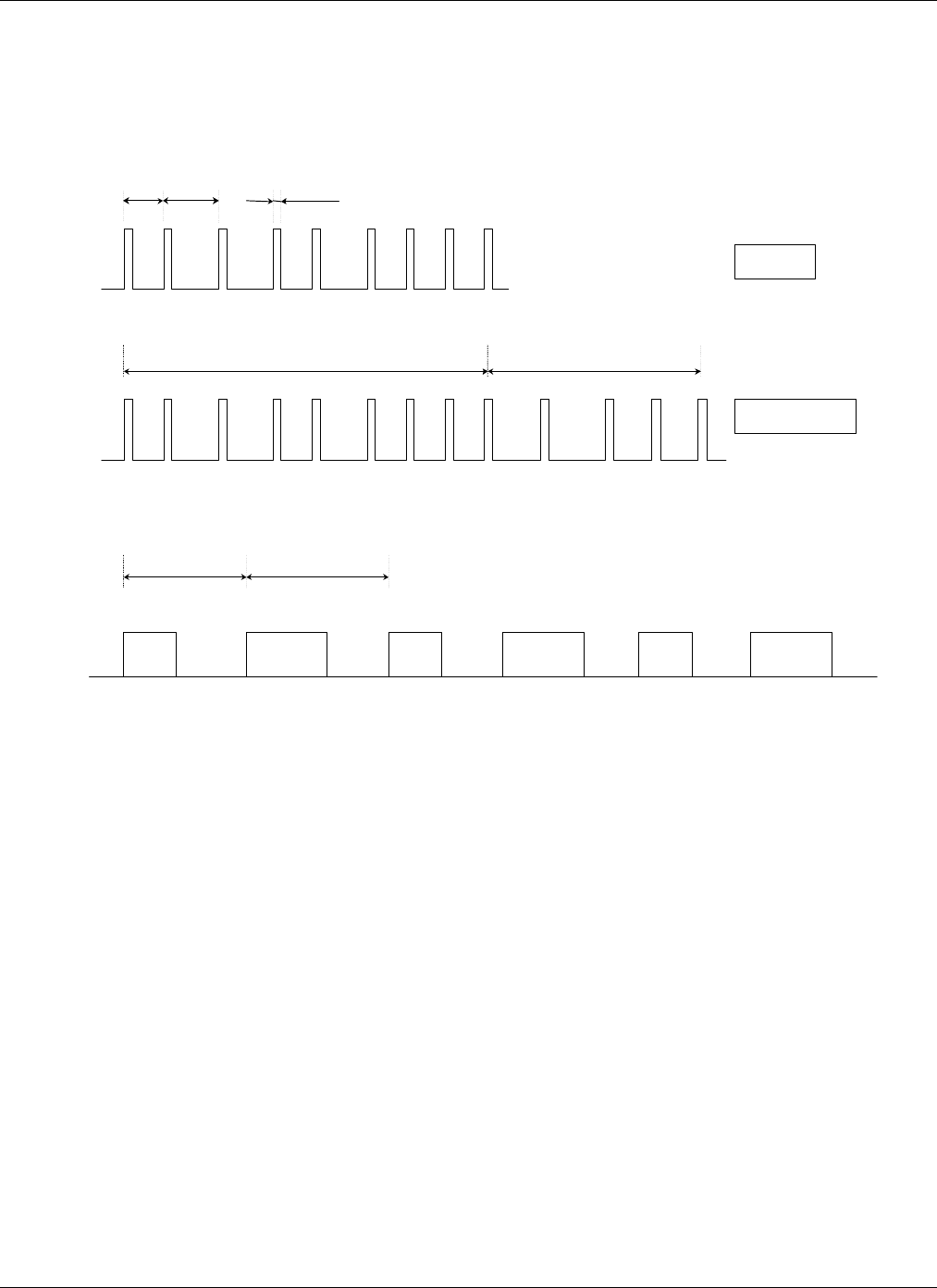
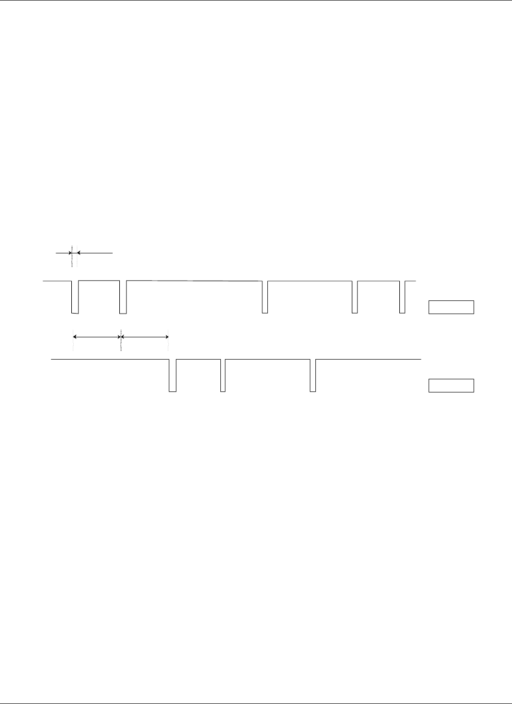
A form of PWM is used to represent ‘zeros’ and ‘ones’. As shown in the Figure 2, a logical ‘1’ is
represented as 2 ms gap between pulses, and a logical ‘0’ as 3 ms gap between pulses. The pulse itself is
500 µs wide.
Figure 2 also illustrates how the “field of coverage” is formed. The Controller alternates between plain
“wakeup word” (97 Hex) and “wakeup + respond word” (97 + 03 Hex). Only the plain “wakeup word”
followed by 20 ms of silence (no pulses) can power up Tag’s processor but not “wakeup + respond word”.
This is important so that Controller wouldn’t be confused with the response it receives from the Tag, not
knowing is it the Tag just powered up or the Tag already “named”. Any pulse that comes within 20 ms after
the plain “wakeup word” (either from the noise or “respond” portion of the “wakeup + respond word” will
advance the hardware counter and microprocessor will not be powered up.
The Tag must receive all 9 pulses of the “wakeup word” and if it misses any of these pulses, the hardware
counter will reset and it will wait for the next plain “wakeup word”.
After it is powered up, the microprocessor will set one of its lines and maintain its own power supply. If
this line is not set within 40 ms it will be powered down again.
“Halo” System: Communication Protocol 970-00002-000
EXI Wireless Systems, Confidential Page 12 of 33 July 27, 1999
4.1.2. Bit By Bit Interrogation
Upon power up the microprocessor waits for the next “wakeup word”. If there would be no ‘unnamed” tags
in the field the next word would be “wakeup + respond word”. However in this case, there is at least one
“unnamed” tag in the field and this will change Controller’s response.
The new Tag (or Tags if there is more then one new Tag) will respond with the pulse (“blip”) immediately
after it receives first 8 bits (9 pulses) from the Controller. When the Controller receives this “blip”, it
knows there is an unknown Tag in the field and instead of continuing with the “RESPOND” command
(0011), it sends “BIT BY BIT” command (0110). Only “unnamed” Tags will find this command of interest
and prepare for the BBB interrogation that follows.
The purpose of this interrogation is to overcome collision problems among different Tags if they try to
communicate to the Controller at the same time. In total 24 bits (3 bytes) need to be transferred from the
Tag to the Controller. This is Tag’s ID number.
One and only one Tag will finish interrogation and it will be the Tag with the highest ID number among all
“unnamed” Tags. All other Tags will, one by one, drop out of this interrogation after they try to send the ’0’
bit when there is a Tag which is sending the ‘1’ bit at the same time. This is the main principle of the BBB
interrogation and detailed description of this protocol can be found in the document “Bit By Bit
Interrogation: Protocol Description, EXI, 1999”.
Figure 2 Wakeup Word
‘1’
‘0’
2 ms
3 ms
500
µ
s
‘0’
‘0’
‘1’
‘1’
‘1’
‘1’
‘1’
‘0’
WAKEUP
‘0’
‘0’
‘1’
‘1’
‘1’
‘1’
‘0’
‘1’
‘0’
‘1’
RESPOND
WAKEUP
WORD
WAKEUP + RESPOND
WORD
100 ms 100 ms
WAKEUP
WAKEUP
WAKEUP
WAKEUP
+
RESPOND
WAKEUP
+
RESPOND
WAKEUP
+
RESPOND
“Halo” System: Communication Protocol 970-00002-000
EXI Wireless Systems, Confidential Page 13 of 33 July 27, 1999
After it transmits all 24 bits of the ID word (3 bytes are treated as one ID word) in the PWM format, the
Tag sends additional byte in a NRZ (non return to zero) format. This is a checksum of the previous ID word
which will be used by the Controller to ensure that the received ID number is correct.
The main characteristic of the NRZ code is that bits are represented by the duration of the logic state and
not by the logic state itself. A logic ‘1’ is a logic state with duration of 500 µs, and a logic ‘0’ lasts for 250
µs. More about this code can be found in the document “Bit By Bit Interrogation: Protocol Description,
EXI, 1999”.
The checksum is calculated by using “Cyclic Redundancy Code” and this code is describe in details in the
document “Halo” Cyclic Redundancy Check, Algorithm Implementation, EXI, 1999”.
Upon receiving the checksum byte, the Controller will issue either ACK (1010) response or REPEAT
(1111) response depending if calculated checksum has matched received checksum or not. If it receives
ACK response, the Tag knows that the ID number was successfully received by the Controller and it will
not respond anymore to the BBB command. This will enable the Tag with the next sequentially lower ID to
finish BBB interrogation next time.
If the Controller respond with REPEAT, the Tag knows that the checksum did not match and it will retry
next time when it receives “wakeup word”.
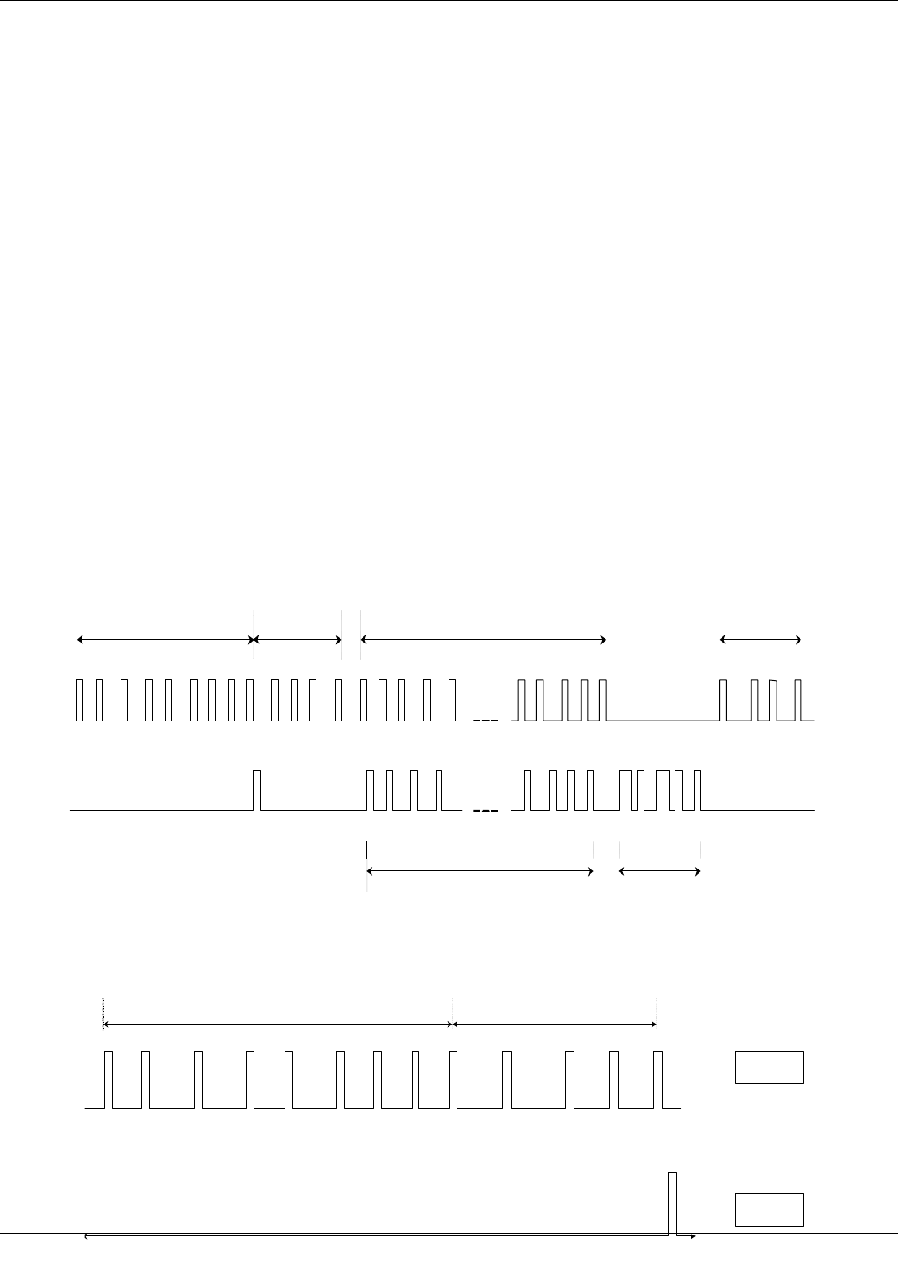
Figure 3 illustrates BBB interrogation.
4.1.3. Respond Command
The Tags which ID number has been retrieved by the Controller are called “named” tags. These tags will
respond to the “wakeup + respond word”, so that the Controller knows if there is anymore Tags in the field
and when they are all gone outside the field of coverage. If there is no “respond” pulses after “wakeup +
respond word” the Controller will terminate TIF alarm and return to the idle mode.
Figure 4 illustrates the Tags response to the “wakeup + respond word”. All tags present in the field and
“named” will respond with the same “blip” (350 µs wide).
Figure 3. Controller TX and RX signals
Wakeup Word
BBB
Command Bit-By-Bit ACK
Data CRC
TX
RX
1 0 0 1 0 1 1 1 0 1 1 0 0 1 1 0 0 1 0 1 1 1 0 1 0
Blip
Figure 2 Controller TX and RX signals
‘1’
‘0’
WAKEUP
‘0’
‘0’
‘1’
‘1’
‘1’
‘1’
‘0’
‘1’
‘0’
‘1’
RESPOND
TX
RX
RESPOND

“Halo” System: Communication Protocol 970-00002-000
EXI Wireless Systems, Confidential Page 14 of 33 July 27, 1999
4.1.4. Reset Command
The Reset command is issued by the Elevator when the door closes. The Elevator needs to know which
Tags are inside the Elevator and in order to force them to send their ID numbers again, it resets them all.
The Elevator will repeat this every time when the door opens and closes.
The Tags are in the sleep mode most of the time while in the field (to preserve power). They wake up once
every second to check if the field is still present. If they receive RESET command (0101) they will reset its
own internal flags which prevent them from responding to the BBB command, and become effectively
“unnamed”.
The Elevator sends RESET command 14 times in a row in order to catch all Tags which were in the sleep.
This RESET commands are spread across 1.4 seconds time interval, and because the Tag is waking up
every I second, all Tags present in the field should be reset.
Figure 4 shows the RESET command
4.2. Tag Initiated Communication (TIC alarm)
Besides being able to detect Tags presence within the “field of coverage”, the other important system’s
feature is to detect when the Tag is in the alarm mode. The conditions that will lead to this alarm mode are
different for different types of Tags. Actually all differences between Tags originate from one characteristic
– how is the alarm generated.
• P-Tag
The P-Tag is attached to the hand of the patient whose movement needs to be monitored and restricted (e.g.
newborn babies). Movement restriction is enforced by the TIF alarm but in order to be effective the P-Tag
must stay attached to the patient all the time. The removal of the P-Tag from the body will generate the TIC
alarm. The P-Tag is attached to the body with the elastic band and it is detecting body capacitance.
• A-Tag
The A-Tag is attached to the asset which movement is restricted (e.g. instrument that should not leave the
building). The movement restriction violation is monitored by the TIF alarms but it can be effective only
while the A-Tag is attached to the protected object. This is ensured by gluing the A-Tag to the asset and if it
is attempted to be removed, the plunger switch will close and generate the TIC alarm.
• D-Tag
The D-Tag is used by the user (e.g. nurse) as a “call for a help” when this person is in a distress. When the
D-Tag is pressed it will close the switch and generate the TIC alarm.
Figure 4 RESET command
‘1’
‘0’
WAKEUP
‘0’
‘0’
‘1’
‘1’
‘1’
‘1’
‘1’
‘0’
‘0’
‘1’
RESET

“Halo” System: Communication Protocol 970-00002-000
EXI Wireless Systems, Confidential Page 15 of 33 July 27, 1999
4.2.1. Message format
The Tag (any of the above) is powered down most of the time and it powers up only when it enters the
“field of coverage” (TIF) or when it needs to generate the TIC alarm.
The TIC alarm range should be much longer than a TIF alarm and this is accomplished with some tradeoffs.
The most important factor is that TIC communication can not be 2-way communication due to the nature
of the Tags 2-way communication (field of coverage has limited range). This determines the format of the
TIC message sent from the Tag to the Controller.
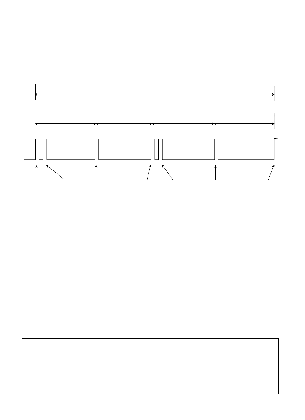
To improve the chances that the message will go through (without the acknowledgment it can not be
guarantied nor the Tag knows if the message has been received correctly by the Controller), it is sent in 3
bursts and 5 times within each burst as shown in the Figure 5. This is 15 ID messages in total sent every
time when the TIC is generated. If any of these messages comes through, the transmission is successful.
After receiving each one of these ID messages the Controller compares received checksum with calculated
CRC and if they are the same, ignores all other messages with the same ID number for next 2 seconds.
The message is formatted in the NRZ code (same protocol as described earlier). Each individual ID
message consists of 3 ID bytes (coded as 6 BCD numbers) and one byte for the checksum (same CRC
calculation as described for “Bit-By-Bit” protocol).
After each burst (with 5 ID messages) the microprocessor goes into the sleep mode. The bursts are
generated every 850 ms (Figure 5a).
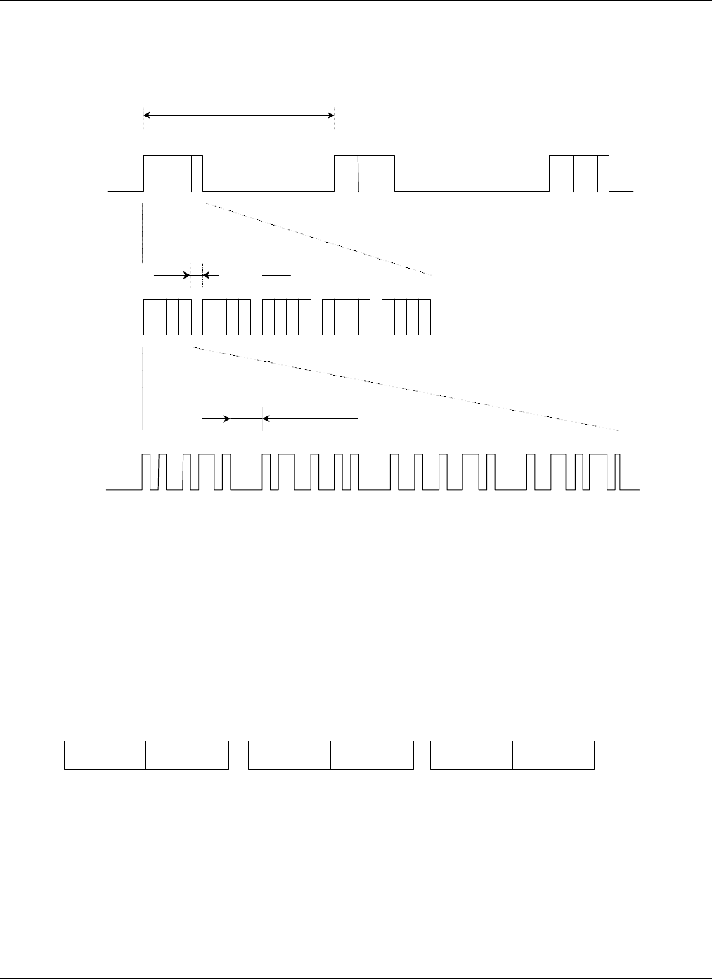
Figure 5b illustrates one of the bursts. The ID messages are separated with 2 ms of silence. This time is
used by the Controller to calculate the CRC.
The ID message format is shown in the Figure 5c. There are 4 bytes in the NRZ code where a logic ‘0’ is
represented with the 250 µs pulse and a logic ‘1’ with the 500 µs pulse. Each byte is terminated with the
“stop bit”. There is 1 ms gap between each byte.
“Halo” System: Communication Protocol 970-00002-000
EXI Wireless Systems, Confidential Page 16 of 33 July 27, 1999
4.2.2. ID number format
Three ID bytes carry information about 6 ID characters in the BCD format (Hexadecimal numbers 0 – F) as
presented in the Figure 6a. All ID numbers are generated as sequential decimal numbers with the exception
of the first character which is always the same for the particular type of Tag
The format of the ID numbers for different tags is as follows:
P-Tag ⇒Cxxxxx
A-Tag ⇒Axxxxx
D-Tag ⇒Dxxxxx
Where “xxxxx” is a sequential decimal number.
Figure 5TIC Alarm
850 ms
2 ms
1 ms
ID 1 ID 3ID 2 CHECKSUM
a)
b)
c)
Figure 6. Format of the ID number
1a 1b 1c 1d 2a 2b 2c 2d 3a 3b 3c 3d 4a 4b 4c 4d 5a 5b 5c 5d 6a 6b 6c 6d
ID BYTE 1 ID BYTE 3ID BYTE 2
“Halo” System: Communication Protocol 970-00002-000
EXI Wireless Systems, Confidential Page 17 of 33 July 27, 1999
5. Weigand Communication Protocol
The Controller communicates to the Host PC through the “RS-485 Interface Module” (RIM). The RIM
sends information to the Controller via control lines and receives information from the Controller via the
Weigand lines. These two communications could take place at the same time due to multitasking nature of
the Controller’s and RIM’s firmware.
5.1. General
Weigand communication protocol is unidirectional protocol developed for card readers. Information is
transferred over two data lines, one used to transfer ‘zeroes’ and the other for ‘ones’. Timing is strictly
defined and is shown in the Figure 7.
Both lines are pulled high in the idle state so that receiver can detect line failure (if it stays low for more
then 50 µs). The signals in the Figure 7 represent one byte of data (CB Hex). Only one line can be pulled
low every 1 ms.
Because the receiver of this signal is sampling these two lines within tightly controlled 47 µs loops (once
every 47 µs), it is very important to keep the timing of these signals on target, especially duration of the 50
µs low pulse. If this pulse would happen to be shorter then 47 µs it could be missed by the receiver.
5.2. Weigand Messages
All information that Controller needs to pass to the Host PC is packed into the 32 bit long, predefined
packets and sent to the RIM over the Weigand lines. The format of these packets is shown in the Table 1
and each one of these fields will be discussed separately.
Figure 7Weigand Protocol
WEIGAND 1
WEIGAND 0
50
µ
s
1 ms
1 1001 110
1 ms

“Halo” System: Communication Protocol 970-00002-000
EXI Wireless Systems, Confidential Page 18 of 33 July 27, 1999
Table 2Weigand Message
Field Length Description
Even Parity Bit 1Parity Bit + next 16 bits = 0
Control Code 4Defines message type
Door Bit 11 = Door Open, 0 = Door Closed
Maglock Bit 11 = Maglock On, 0 = Maglock Off
Data 1 8Dependant on message type
Data 2 8Dependant on message type
Data 3 8Dependant on message type
Odd Parity Bit 1Odd Bit + previous 16 bits = 1
Total 32
5.2.1. Parity Bits (Even and Odd)
These two one-bit fields are used for error detection and they are starting and terminating the packet.
The “Even Parity Bit” is calculated for the first 16 bits. They are added in the Boolean algebra without
Carry (0+0=0, 0+1=1, 1+0=1, 1+1=0) and if this result is 0 the “Even Parity Bit” is set to ‘1’ and vice
versa.
The “Odd Parity Bit” is calculated for the last 16 bits and if this result is 0, the “odd Parity Bit” is set to ‘1’
and vice versa.
Figure 8 illustrates how are these bits calculated. The same calculation is conducted on the receiving side
(RIM) and if received and calculated parity bits match, the transmission is considered successful.
Figure 8
Σ + EPB = 0
EVEN
PARITY
BIT
Σ + OPB = 1
ODD
PARITY
BIT

“Halo” System: Communication Protocol 970-00002-000
EXI Wireless Systems, Confidential Page 19 of 33 July 27, 1999
5.2.2. Control Code
This 4-bit field identifies message type. A content of three data bytes (Data 1, Data 2 and Data 3) is
determined by this field.
There are two groups of message types, messages which carry Tag’s ID number and all others. An overview
of all message types is presented in the Table 2.
Table 3
Message Type Control
Code
Data 1 Data 2 Data 3
Tag ID (byte 1) Tag ID (byte 2) Tag ID (byte 3)
Normal 0 (0000) AB C DEF
Bypassed 4 (0100) AB C DEF
TIF Alarm 1 (0001) AB C DEF
Loiter 3 (0011) AB C DEF
Host Alarm is ON 2 (0010) AB C DEF
Unlock Req. is ON 5 (0101) AB C DEF
TIC Alarm 7 (0111) AB C DEF
ID Messages
Test Mode 10 (1010) AB C DEF
PIN # Entry 8 (1000) Key Key Key Key Key Key
Event (Door Open) 9 (1001) 00 00 01
Switches
configuration
11 (1011) Version # Mode / Option ID Range
No ID
Status 12 (1100) Noise Counter Input States Device Status
‘ID’ Messages
Messages which carry Tag ID number are prioritized not according to their code numbers but rather as
shown in the above table (‘Normal’ is the lowest priority and ‘Test Mode’ is the highest priority).
5.2.2.1. Normal
Message sent when the “good” Tag enters the field of coverage. “Good” Tag will not trigger the alarm.
5.2.2.2. Bypassed
This message is sent when the Controller enters ‘bypass’ mode. In this mode Tags can enter the field of
coverage without triggering the alarm. This mode is enabled by the user from the keypad or the RBC. If not
interrupted by the user, this mode will expire after 60 seconds and the Controller will revert into the
Normal mode.
5.2.2.3. TIF Alarm
This message is sent when the “bad” Tag enters the field of coverage. “Bad” Tag triggers the alarm.
5.2.2.4. Loiter
Message sent when the field is occupied for more then 1 minute with no new Tags coming in.

“Halo” System: Communication Protocol 970-00002-000
EXI Wireless Systems, Confidential Page 20 of 33 July 27, 1999
5.2.2.5. Host Alarm ON
Message which informs the host that its command to set the alarm has been received and that the Controller
is in the alarm mode.
5.2.2.6. Unlock Request ON
Message which informs the Host that its command to unlock the door has been received and the door is
unlocked.
5.2.2.7. TIC Alarm
Message sent when TIC alarm is received from the Tag. This is the message with the highest priority when
the system is in the normal operating mode (not in the Test mode)
5.2.2.8. Test Mode
Message sent when the Controller is in the Test mode (set by the switch inside the Controller). No alarms
are set in this mode and it is usually used to set the field of coverage.
‘No ID’ Messages
These messages carry information about the system status. They have lower priority then ID messages.
5.2.2.9. Pin Number Entry
This message carries to the Host up to 6 keys entered from the keypad. To distinguish between a key “0”
and no key, the key “0” is coded as “A” (1010 Hex), and no key is coded as “0” (0000 Hex). If more then 6
keys are entered, only last 6 are sent to the controller.
5.2.2.10. Event (Door Open)
Message applicable to Elevators only. It is sent when the elevator door opens. This message is passed to the
RIM every time when the door changes state, but the RIM sends this message to the Host only if the
Elevator door has not changed its state for some time.
5.2.2.11. Switch Configuration
This message carries information about the Controller setup selectable by the installer by rotary switches
and about firmware version. Three data bytes are assigned as follows:
1. Version Number (Version of firmware)
2. Mode / Option
Following table illustrates Mode switch configuration and related modes of operation.
Table 4
Mode Controller Function Response
0Test Mode Alarm ends on its own – fixed bypass time
1Patient Monitoring with RBC Continuos alarm – fixed bypass time
2Patient Monitoring with RBC Alarm ends on its own – fixed bypass time

“Halo” System: Communication Protocol 970-00002-000
EXI Wireless Systems, Confidential Page 21 of 33 July 27, 1999
3Patient Monitoring Continuos alarm – fixed bypass time
4Patient Monitoring Alarm ends on its own – fixed bypass time
5Article Surveillance - Protection Alarm ends on its own – bypass extended
6Article Surveillance – Protection Alarm ends on its own – bypass extended
7, 8, 9 Reserved (Article Surveillance–Monitoring)
AAuthorized Entry 4 second release
BAuthorized Entry 8 second release
CAuthorized Entry Released while Tag in the field
D,E,F No Function
Modes 1 and 2 will only allow bypass when the field is cleared of Tags and the user enters a sequence
of key presses on the RBC. Modes 3 and 4 and modes 5 and 6 are for Keypad entry. Pinpad can be used
with any of the modes.
3. ID Range
This field is defined by the “ID Range” rotary switch on the Controller. It determines which Tags will
trigger the TIF alarm (“bad” Tags) and which will be ignored (“good” Tags).
For options 2 – D, “High_ID” and “Low_ID” rotary switches are used to determine range in which
Tags are active. When one of these options is chosen, this field (ID Range rotary switch) selects which
digit of Tag’s 6 digit ID number is making selection. Tag’s ID number is organized as ABCDEF where
each character represents one digit of the ID number.
Possible settings are presented in Table 4.
Table 5“ID Range” Switch
Option Active Tags Mode: 1,2,3,4,5,6 Mode: A,B,C
0Don’t act on any Tags No Tags are stopped No Tags authorized
1Act on all Tags All Tags are stopped All Tags authorized
2Tag Selection on digit A Selected Tags are stopped Selected = Alarm
3Tag Selection on digit B Selected Tags are stopped Selected = Alarm
4Tag Selection on digit C Selected Tags are stopped Selected = Alarm
5Tag Selection on digit D Selected Tags are stopped Selected = Alarm
6Tag Selection on digit E Selected Tags are stopped Selected = Alarm
7Tag Selection on digit F Selected Tags are stopped Selected = Alarm
8Tag Selection on digit A Selected Tags can pass Selected = Pass
9Tag Selection on digit B Selected Tags can pass Selected = Pass
ATag Selection on digit C Selected Tags can pass Selected = Pass
BTag Selection on digit D Selected Tags can pass Selected = Pass
CTag Selection on digit E Selected Tags can pass Selected = Pass
DTag Selection on digit F Selected Tags can pass Selected = Pass
E, F Not used
Only options 0 and 1 will not use switches “High_ID” and “Low_ID” to select particular range of Tag
Ids (these two options deal with all Tags). All other “ID Range” switch settings will use them as
illustrated in Table 4.

“Halo” System: Communication Protocol 970-00002-000
EXI Wireless Systems, Confidential Page 22 of 33 July 27, 1999
Table 6“High_ID” and “Low_ID” Switch
Switch Setting Selected Tags
High_ID > Low_ID All Tags with selected digit (switch ID Range) equal or between the
two numbers are selected.
High_ID < Low_ID All Tags with selected digit (switch ID Range) lower then or equal
to “High_ID” and all Tags with selected digit greater or equal of
“Low_ID” are selected
High_ID = Low_ID Only Tags with selected digit (switch ID Range) equal “High_ID”
(or “Low_ID”) are selected
5.2.2.12. Status
Status message carries information about Controller’s status, input states and RF noise level. These
messages are requested by the Host every 30 seconds to confirm that the Controller is still present on the
bus and functioning properly. The Controller will send this message on its own if any parameter is changed
(as with any other message).
There are three data bytes in the Status message:
1. Noise Counter
Indicates number of times the Controller has detected signal on its receiver but that was not legitimate
data. The Controller is sampling receiver every 50 µs. This counter decrements over time (10 times
faster then it increments) if noise goes away. When the noise counter reaches 100, the Status message
is sent, and then again when the counter gets back to zero.
2. Input States
This byte describes the state of all inputs to the Controller as shown in the Table 6
Table 7Input States
Bit Input Name Function
Bit 7 Not used
Bit 6 Strobe 0 – ignore other host inputs
1 – host inputs active (override, unlock, alarm)
Bit 5 Override 0 – override request
1 – no override request
Bit 4 Unlock 0 – lock release request
1 – no lock release request
Bit 3 Bypass key 1 – bypass key pressed
Bit 2 Reset key 1 – reset key pressed
Bit 1 Alarm 0 – host alarm request
1 – no host alarm request

“Halo” System: Communication Protocol 970-00002-000
EXI Wireless Systems, Confidential Page 23 of 33 July 27, 1999
Bit 0 Door 0 – door closed
1 – door open
When in the idle mode, the Input States field equals 73 Hex.
3. Device Status
This byte describes the Controller’s state.
Table 8Device Status
bit State Description
Bit 7 Not used
Bit 6 RF field occupied Tag is in the field, regardless if it generates alarm or not.
Bit 5 Override Host requested. Controller releases the maglock, turn off
alarm relay and both LEDs and stop all interrogation.
Bit 4 Unlock Host requested. Maglock is released, current alarm is cleared.
Bit 3 Bypass Controller is in the bypass mode.
Bit 2 Host alarm Host requested. Maglock, alarm LED and relay activated,
Bit 1 TIC alarm TIC received from the Tag
Bit 0 TIF alarm TIF received from the Tag

“Halo” System: Communication Protocol 970-00002-000
EXI Wireless Systems, Confidential Page 24 of 33 July 27, 1999
6. Signal lines communication
The Weigand protocol which is unidirectional is used to transfer information from the Controller to the
RIM. Some information (mostly Host requests) need to be passed from the RIM to the Controller. There
are 4 signal lines that are used for this purpose and the Controller monitors these lines every 12.8 ms.
There are two modes of operation for the Control lines. When the “Strobe” line is high, the other 3 lines are
treated individually, and when the “Strobe” is low they are treated as a 3-bit command for the Controller.
Signal lines functionality is shown in the Table 8.
Table 9
Strobe
Override
Unlock
Alarm
Functionality
0000Return to normal mode, end any other mode
0001Send current status
0010Send switch settings
0011Start bypass
0100Reset all Tags in the field and reread them
0101Remote reset key press, clears distress alarm
0110Enter Reader mode / acknowledge Tag
0111Retransmit Tag (only until next Tag comes in)
10x x Start Override
1x0xStart Unlock (Controller only)
Start Bypass (Elevator only)
1xx0Start Host alarm
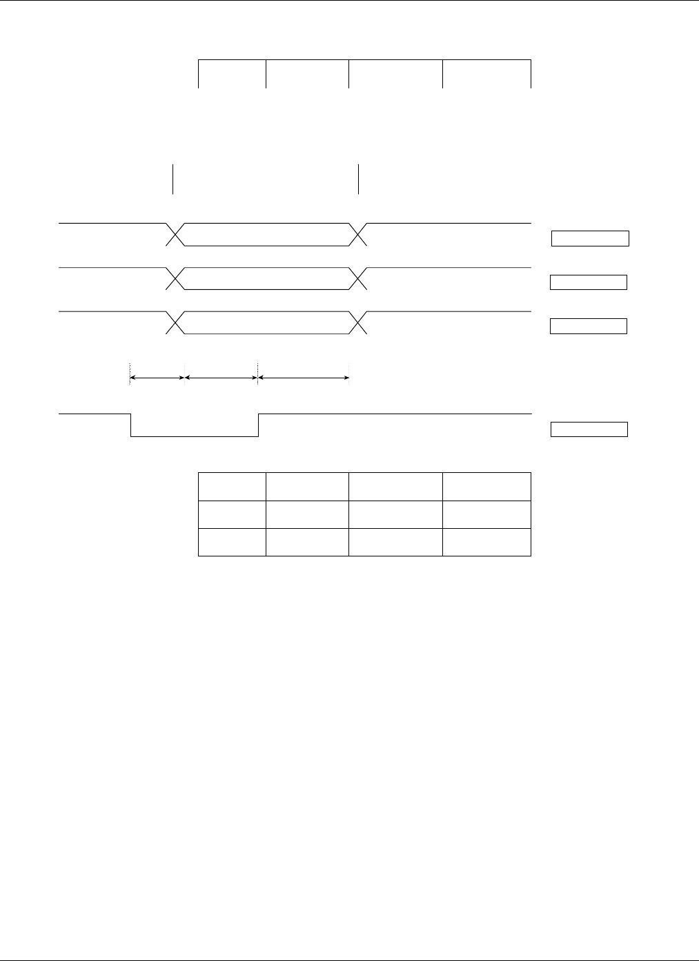
When there is a need to transfer the command to the Controller some timing guidelines must be followed
as illustrated in the Figure 9. This is necessary in order to preserve integrity of command lines and the fact
that even when control lines are reset to their normal state (all 3 high), the Controller needs this
information to operate properly.
After the “Strobe” signal returns to high state, the signals on the control lines should return to their
previous state before the “Strobe” signal become low. They should be returned within 52 ms from the
rising edge of the “Strobe” signal.
NOTE: Receiver is not able to respond to this communication since it has no control input lines
“Halo” System: Communication Protocol 970-00002-000
EXI Wireless Systems, Confidential Page 25 of 33 July 27, 1999
Name Min Typical Max
TS13 ms 50 ms 25 ms
TD1 ms 13 ms 40 ms
TH13 ms 25 ms 50 ms
Figure 9
TSTDTH
OVERRIDE
UNLOCK
ALARM
STROBE
Individual
Lines
Control CodeIndividual
Lines

“Halo” System: Communication Protocol 970-00002-000
EXI Wireless Systems, Confidential Page 26 of 33 July 27, 1999
7. EIA-485 Communication
Information between Controller and the Host computer are exchanged across twisted pair cable driven by
EIA-485 transceivers. The Controller can not communicate directly to the Host but rather through the RIM
which is a network adapter for the Controller. On the Host side, the PC has an EIA-485 network card to
make this link compatible.
7.1. General
The EIA-485 is a hardware specification which determines physical layer only, and doesn’t specify
communication protocol used but imposes some limitations to that protocol in regards to maximum
communication speed, maximum number of nodes allowed on the bus and how these nodes could be
interconnected.
The maximum communication speed and the distance across these nodes are communicating, are closely
linked together and by increasing one parameter, the other must be decreased.
The maximum number of nodes is determined by electrical properties of transceivers and the maximum
number today is 256. These nodes must be linked following a bus topology and the bus must be terminated
at each end to avoid reflections which could significantly degrade network performance.
7.2. Network performance
The 485 network used by the Halo system can operate on three different speeds: 9600, 19200 and 57600
baud. This is selectable by a jumper in the RIM on the one side, and through the Halo program that is
running on the Host PC on the other.
Maximum of 99 nodes is allowed on the bus and the Host is a master. The Host is polling slave nodes in a
round robin fashion. As a consequence of this type of communication, higher number of nodes means that
the system response will be slower.
The system response will slow down even more if the Host software is configured for the non-existing
nodes or if some nodes on the bus are powered down or unable to communicate. For every node that
doesn’t respond to the Host’s request (for any reason), the system response is prolonged approximately 600
ms (the Host waits that long for the response).
If the node responds on the Host’s request, the next request (for the next node) is sent after 55 ms (55 ms is
internal PC tick and messages can not be sent more often). This indicates that expected polling rate is 110
ms per device in a case of reliable communication.
If the Host upon receiving the message sent by the RIM sends “Ack” for that message, but that “Ack” is not
received by the RIM, next time when the Host requests the message from the RIM, the RIM will send the
same message. This could cause additional delay for the message to be displayed on the computer screen.
“Halo” System: Communication Protocol 970-00002-000
EXI Wireless Systems, Confidential Page 27 of 33 July 27, 1999
Figure 10 shows network traffic in a case of two devices on the bus with reliable communication.
Maximum number of nodes to be polled is 9 per second in ideal condition (all node responses are
received). “Host Request” message packet and “RIM” response packet are separated from each other 100 µs
only, and not as shown in the Figure 10.
7.3. Communication parameters
UARTS on both sides (Master and Slave) are configured for asynchronous full duplex mode. Byte format is
1 start bit, 8 data bits and 1 stop bit. Both UARTs transmit and receive LSb first. Standard communication
speed is 57.6 kbaud what refers to 17.36 µs per bit.
7.4. Message format
Messages are initiated by the Host computer and the RIM responds to most of them but not all. Messages in
both directions have the same format and the difference among them is in data they carry (different type and
length of data), but the message structure is the same.
Table 10 illustrates format of these messages.
Table 10 485 Message Format
Bytes Field Description
1SOH Start of Header (01 Hex)
1Length Length of message from (including) a message type to (including)
checksum.
1Message Type Upper 2 bits: message number
Figure 10
HOST
REQUEST
1
RIM 1
RESPONSE
HOST
ACKNOWLEDGMENT
HOST
REQUEST
2
RIM 2
RESPONSE
HOST
ACKNOWLEDGMENT
HOST
REQUEST
1
55 ms 55 ms 55 ms 55 ms
FULL CYCLE: 2x110 ms = 220 ms

“Halo” System: Communication Protocol 970-00002-000
EXI Wireless Systems, Confidential Page 28 of 33 July 27, 1999
Lower 6 bits: message type
1Network
Address Logical address assigned by the Host
XData Message contents. Number of bytes is variable, it could be 0.
1Checksum All bytes added and inverted
Note: SOH character (01 Hex) defines start of the message and in a case that the same value (01 Hex) is
part of the rest of the message that byte is converted by using ESC character in the following
manner:
01 Hex (SOH) ⇒ 1B Hex 31 Hex (ESC ‘1’)
1B Hex (ESC) ⇒ 1B Hex 1B Hex (ESC ESC)
This conversion is done to avoid byte “01” Hex within the message to be considered as a start of the
new message.
The “Message Type” field is divided into two sub-fields, one is actual message type and the other (upper
two bits) is a counter (“message number”) which is advanced every time when the message is sent to the
particular RIM. Upon receiving the message from the host, the RIM advances its own message counter
which should be in sync with the received “message number”. If these two counters do not match, it
indicates to the RIM that it has missed at least one message from the Host.
7.5. Message Structure
All messages types are initiated by the Host, but not all of them are sent by the Host. Four message types
are sent by the Host, and the rest is sent by the RIMs as a response to Host’s messages. All message types
are listed in the Table 11
Table 11 Message Types
Asign
Network
Address
Test Node
Presence Node
Present Send /
Request
Data
Device
Data Host Ack
Length 6 6 4 4 4 + (N * 4) 3
Type 234567
Address Network
Address 00 00 or
Network
Address
Network
Address Network
Address Network
Address
Data Serial
Number Serial
Number Firmware
version # Control
Byte Status byte
7.5.1. Assign Network address
This message is sent by the Host when the network is configured. Part of network setup is to assign
network address to each device on the bus (each RIM). In order to do this, installer needs to know RIM’s ID
number (6 digit number). This message is then sent to that particular RIM which will use this number in all
future communication to the Host.

“Halo” System: Communication Protocol 970-00002-000
EXI Wireless Systems, Confidential Page 29 of 33 July 27, 1999
The RIM does not respond to this message, but the Host knows if the message has been successfully
received when the RIM responds next time to other messages sent to its network address. If the RIM does
not respond to those messages, the Host keeps sending “Assign Network Address’ message.
7.5.2. Test Node Presence
This message allows the Host to check if the particular node (RIM) is present on the bus and is it able to
communicate. All nodes are listening to this message, but only one with matching serial number will
respond with its communication firmware version.
7.5.3. Node Present
This message is sent from the RIM as a response to the “Test Node Presence” message. With this response,
the RIM indicates to the Host that is present on the bus and able to communicate. If it still doesn’t have its
network address, the RIM will respond with ‘00’ as the address, and to the Host this will be the signal to
assign network address to this node.
7.5.4. Send / Request Data
This is normal communication message between the Host and the other nodes on the bus. This message
communicates to one node at the time and it is used to send commands to the Controller and as a request to
the same Controller to send its data.
The command for the Controller (control byte) has two fields. First field (bits 6, 5, 4) is used to set
individual Controller’s output lines (Alarm, Unlock, Override) and the other (bits 3, 2, 1 ,0) to request
some action from the Controller. Note that both fields are actually controlling Controller’s output lines
(Strobe, Alarm, Unlock and Override) as described earlier in the chapter “Signal Lines Communication”.
Detail description of the control byte is shown in the Table 12
Table 12 Control byte
7 6 5 4 3 2 1 0 Function
1 x x x x x x x Prevents ‘01’ (SOH) or ‘1B’ (ESC)
x 0 0 0 x x x x All lines OFF
x 0 0 1 x x x x Alarm line ON
x 0 1 0 x x x x Unlock line ON
x 0 1 1 x x x x Unlock and Alarm ON
Individual Lines
x 1 0 0 x x x x Override line ON
x x x x 0 0 0 0 Return to idle mode (end bypass, alarm, maglock…)
x x x x 0 0 0 1 Send current status
x x x x 0 0 1 0 Send switch setting
x x x x 0 0 1 1 Start bypass
x x x x 0 1 0 0 Re-read Tags (reset all Tags)
H
o
st
R
e
q
u
es
t
x x x x 0 1 0 1 Remote “Reset” key press (same as “Reset” key on RBC)

“Halo” System: Communication Protocol 970-00002-000
EXI Wireless Systems, Confidential Page 30 of 33 July 27, 1999
x x x x 0 1 1 0 Enter Reader mode (Controller only)
Restart Pre-alarm mode (Elevator only)
x x x x 0 1 1 1 Retransmit last Tag
x x x x 1 0 0 0 None
7.5.5. Device Data
This message is sent as a response to the “Send / Request Data” message. It follows request message
within 150 µs. The length of this message is not predictable and it depends on system activity. Any TIC or
TIF alarms are reported with this message and if multiple TIC or TIF alarms are available in the RIM’s
buffer, they will be all sent within one message.
Fixed portion of “device Data” message includes device “Status byte”. This information is sent every time
regardless if there are any alarms or not. It mostly describes communication quality between Host and the
Controller.
Table 13 Status Byte
bit Condition Set Clear
7No Weigands from device 1 minute with no Weigands Weigand comm. OK
6Attached device not connected Weigand lines low Weigand lines high
5Problems communicating to Host Errors during receiving on 485 “Ack” received
4Last message was out of order Messages not in sequence “Ack” received
3Lost Weigand message Weigand parity check failed “Ack” received
2Buffer overflow Lost message due to too many
Weigands since last pool “Ack” received
1Designated monitor “Start Monitoring” message “Stop Monitoring” message
0= 0, To prevent ‘01’ or ‘1B’ Never Always
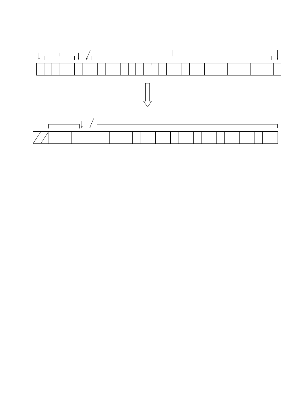
When TIC or TIF alarm needs to be sent, it is added after the Status byte. The Weigand message received
from the Controller is stripped of parity bits and the rest of the message is shifted to the right for one bit .
The result is four byte field as shown in the Figure 11 First figure shows Weigand message as received
from the Controller, and second one shows same message ready to be appended to the “Device Data”
message.. First two bits are always ‘0’.
“Halo” System: Communication Protocol 970-00002-000
EXI Wireless Systems, Confidential Page 31 of 33 July 27, 1999
Figure 11
CODE
EVEN
PARITY
BIT TAG ID
ODD
PARITY
BIT
DOOR
MAGLOCK
CODE TAG ID
DOOR MAGLOCK

“Halo” System: Communication Protocol 970-00002-000
EXI Wireless Systems, Confidential Page 32 of 33 July 27, 1999
8. Glossary
Checksum A number that has been calculated as a function of some message.
CRC Cyclic Redundancy Code" or “Cyclic Redundancy Check”.
LSb Stands for “Least Significant Bit”. This is bit 0 of a given byte or a word.
MSb Stands for “Most Significant Bit”.
Message Sequence of bytes which carry information from one point to the other.
EIA-485 Balanced, multidrop, half-duplex communication protocol (former (RS-485)
EIA-232 Unbalanced, point-to-point communication protocol.(former (RS-485)
PWM Pulse Wide Modulation
BBB Bit By bit Interrogation
Maglock Door lock controlled by the magnetic coil.
RBC Remote Bypass Control
UART Universal Asynchronous Receiver and Transmitter

“Halo” System: Communication Protocol 970-00002-000
EXI Wireless Systems, Confidential Page 33 of 33 July 27, 1999
9. References
“Bit By Bit Interrogation; Protocol Description”,EXI, 1999
“ROAM II Patient Protection System, RS485 Interface Modules; Functional Requirements Specification”,
EXI, 1999
“Halo Cyclic Redundancy Check; Algorithm Implementation”, EXI, 1999
“ROAM II Controller Functional Specification, EXI, 1999
“MAX System Description”, EXI, 1999