Xmark R2R SUPERHETERODYNE RECEIVER User Manual R2
Xmark Corporation SUPERHETERODYNE RECEIVER R2
Xmark >
Contents
- 1. Communication Protocol manual
- 2. Installation manual
- 3. User manual
Installation manual

© Copyright 1999, EXI Wireless Systems Inc. All rights reserved.
Installation Manual
for
Controllers and Receivers
June, 1999
EXI HALO Installation Manual Rev 2.0
EXI Wireless Systems Inc. Page 2June, 1999
Revisions
Date Changed by Description
6/9/99 Zahir Abji First Release
6/17/99 Zahir Abji System Wiring section added and Halo
Wiring Diagram corrected
Any changes or modifications not expressly approved by the manufacturer could void the user’s authority to oper-
ate the equipment.
NOTICE: This equipment has been tested and found to comply with the limits of a class B digital device, pursuant to
Part 15 of the FCC rules. These limits are designed to provide reasonable protection against harmful interference in a
residential installation. This equipment generates, uses and can radiate radio frequency energy and, if not installed and
used in accordance with the instructions, may cause harmful interference to radio communications. However, there is
no guarantee that interference will not occur in a particular installation. If this equipment does cause harmful inter-
ference to radio or television reception, which can be determined by turning the equipment off and on, the user is en-
couraged to try and correct the interference by one or more of the following measures. (1) Reorient or locate the re-
ceiving antenna. (2) Increase separation between the equipment and the receiver. (3) Connect the equipment into an
outlet on a circuit different from that to which the receiver is connected. (4) Consult the dealer or an experienced
radio/TV technician for help.
NOTICE: Operation is subject to the following two conditions: (1) This device may not cause interference, and
(2) This device must accept any interference, including interference that may cause undesired operation of the
device.

EXI HALO Installation Manual Rev 2.0
EXI Wireless Systems Inc. Page 3June, 1999
LIMITED WARRANTY
EXI Electronic Systems a division of Diversity Products Ltd. (collectively, “EXI”) hereby warrants the prod-
uct(s) accompanying this limited warranty (the “Product(s)”) to be free of defects in materials and workmanship
for a period of two years (excluding any batteries that may be added to or used in conjunction with the Prod-
ucts(s)) from the date of delivery of the original purchase of the Product(s) subject to the limiting conditions set
forth below, provided that EXI has received notification of such defects no later than 30 days after expiration of
the applicable warranty period and provided further that EXI has received a fully completed registration card
(below) within 30 days from the date of original purchase of the Product(s).
The responsibility of EXI under this warranty is and shall be limited to repairing or replacing the Product(s) or
any part thereof determined by EXI in its sole discretion to be defective in workmanship or material.
The installation of the Product(s) shall be deemed as acceptance by the original purchaser and any subsequent
purchaser of the Product(s) (collectively the “Purchaser”) of the terms set out in this limited warranty including
the following further limiting conditions:
(a)EXI shall not be responsible for any repair or replacement of any Product(s) which has been found, upon
inspection, to have been subjected to abuse, misuse or negligence, or any damage attributable to accident, light-
ning, power surge, brown-out, leaking, damaged or inoperative batteries or to have been installed, altered or
repaired contrary to factory designated procedures without the prior written consent of EXI;
(b)It is understood, and the Purchaser agrees further to so inform any user of the Product(s) that the Product(s)
is not, nor can it be, infallible in the detection of wandering patients, the prevention of infant abduction, the pre-
vention of theft of assets or any other contemplated use of the Product(s). The Purchaser will warn all users
and acknowledges on it’s own behalf that it has read and understands the above-mentioned limitations of
the Product(s). The Purchaser further acknowledges that the Product(s) are solely intended to provide an addi-
tional safeguard in notifying staff and accordingly do not guarantee the prevention of wandering patients or the
attempted abduction of an infant or the theft of assets;
(c)It is further agreed by the Purchaser that the Purchaser has received no additional promises or statements of
fact from EXI or its agents relative to the Product(s) upon which the Purchaser might have relied in purchasing
the Product(s);
(d)The warranty set out above excludes and is in lieu of all other express or implied warranties, conditions or
obligations, and no person is authorized to give any further representation or warranty or assume any further
obligation on behalf of EXI. Although the Purchaser may have other rights, as they may vary from State to State
or Province to Province, where it is legally possible to do so any statutory warranty is hereby expressly ex-
cluded. The warranty is subject to the domestic laws of the Province of Manitoba, Canada and the Purchaser
agrees to attorn to the jurisdiction of the courts of competent jurisdiction in the Province of Manitoba; and
(e)EXI shall not be liable for any damages, whether direct or, indirect, incidental, consequential or arising out
of contact or tort with the sole exception of the warranty set out above and any rights expressly created by appli-
cable statute.
THIS WARRANTY IS VALID ONLY IN THE USA AND CANADA

EXI HALO Installation Manual Rev 2.0
EXI Wireless Systems Inc. Page 4June, 1999
Table of Contents
1. INTRODUCTION..............................................................................................................................................5
1.1. INTENDED AUDIENCE ...................................................................................................................................5
1.2. SYSTEM OPERATION..............................................................................................................................5
2. DECISIONS TO MAKE PRIOR TO INSTALLATION.............................................................................6
2.1. SYSTEM WIRING......................................................................................................................................6
2.2. CONTROLLER CONFIGURATIONS......................................................................................................7
2.3. LOCATION FOR SRA EXCITER ANTENNAS......................................................................................7
2.4. KEYPAD OR PINPAD? ............................................................................................................................9
2.5. LOCATING THE RECEIVER ANTENNA..............................................................................................9
3. INSTALLATION PROCEDURES...............................................................................................................10
3.1. INSTALLING CONTROLLERS..............................................................................................................10
3.1.1. PREPARE CONTROLLER FOR FIELD SET UP.........................................................................10
3.1.2. TEST CONTROLLER AND SET UP FIELDS...............................................................................11
3.1.3. FINALIZE CONTROLLER INSTALLATION.................................................................................12
3.1.4. SET CONTROLLER SWITCHES FOR NORMAL OPERATION.................................................13
INSTALL RECEIVERS........................................................................................................................................15
3.3. TESTING TIC ALARM COVERAGE AROUND THE BUILDING ....................................................15
3.4. CONNECTING TO THE HOST COMPUTER ......................................................................................16
4. WEIGAND OUTPUT SPECIFICATION....................................................................................................19
Figure 1 - Controller Operation...............................................................................................................................5
Figure 2 - "Bus" Topology Figure 3 - "Star Topology........................................................................................6
Figure 4 - Typical HALO Configuration..................................................................................................................6
Figure 5 – Antenna Field...........................................................................................................................................8
Figure 6 - HALO Controller Typical Hook-up Diagram......................................................................................10
Figure 7 - Securing the Exciter Antenna Cable .....................................................................................................12
Figure 8 – Controller Switch Identification...........................................................................................................13
Figure 9 – HALO Receiver.......................................................................................................................................15
Figure 10 – HALO Receiver Threshold and Operating Voltage Setting.............................................................15
Figure 11 – HALO Network with Host Computer..................................................................................................16
Figure 12 – Sketch of RIM.......................................................................................................................................16
Figure 13 – HALO System Grounding...................................................................................................................17
Figure 14 - Halo Wiring Diagram..........................................................................................................................18
EXI HALO Installation Manual Rev 2.0
EXI Wireless Systems Inc. Page 5June, 1999
1. INTRODUCTION
1.1. Intended Audience
This manual serves as a guide for Installers of the HALO system. The major components of the system
are described, as well as the system’s intended functionality, so as to gain familiarity with its operation
prior to installation. In order to successfully install and commission the system, it is absolutely critical
to understand the capabilities of the system and its components prior to installation.
The function of the HALO system is to monitor areas within a building for the presence of HALO
Tags. A Tag is sensed when it either enters an RF Field that is set up using the EXI HALO Controller
(referred to as a Tag in Field or TIF), or when the Tag initiates an alarm signal (referred to as Tag Initi-
ated Communications, or TIC).
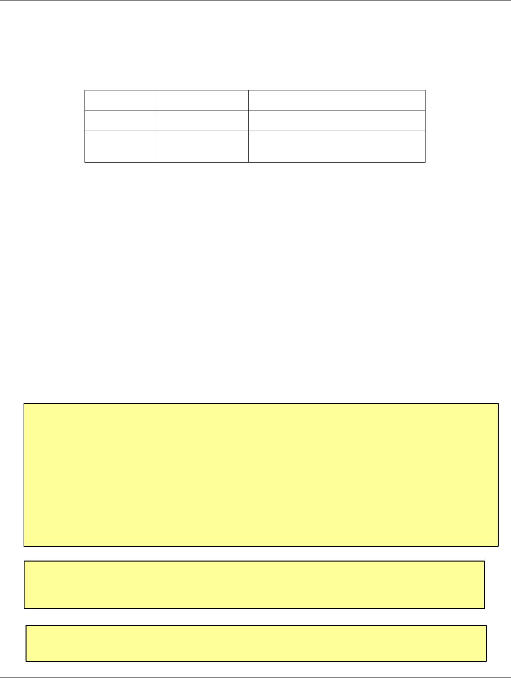
1.2. SYSTEM OPERATION
The EXI HALO system uses Radio Frequency waves for communications between the HALO system
components and the Tags. The HALO Controller continuously emits a 307 kHz RF frequency via the
Exciter Antenna, setting up a field in its local area. When a Tag enters this field, a Radio Receiver
within the Tag senses the 307 kHz RF field and transmits its identification information to the HALO
Controller using a low level Radio Signal at frequency of 434 MHz.
Figure 1 - Controller Operation
RECEIVE
ANTENNA RBC
FCC ID# HE7MAX
TRANSMIT OUTPUT
SEA #1 SEA #2
Made in Canada . . with care Controller
by
Power
1 2 3 4 5 6 7 8 9 10 11 12 13 14 15 16 17 18 19 20
+24V DC Input
System Ground
+12V Ou 200 ma
System Ground
Weigand 0/Data
Weigand 1/Gnd
System Ground
MagOut 24V 200 ma
Door Switch In
System Ground
Unlock In
Override In
Strobe In
N.O
COM
N.C.
N.O
COM
N.C
Relay #1 Relay #2
Alarm In
OFF ON
EXI ELECTRONIC SYSTEMS
Winnipeg, Manitoba (204) 788-1696
Made in Canada
PRODUCT
MODEL NO.
SERIAL NO>
ROAM II/TAGRRR
SEA-M
1118
HALO Controller
RX
Antenna SRA
Exciter
Antenna
434 MHz 307 KHz
Transponder
EXI HALO Installation Manual Rev 2.0
EXI Wireless Systems Inc. Page 6June, 1999
2. DECISIONS TO MAKE PRIOR TO INSTALLATION
2.1. SYSTEM WIRING
The HALO network is based on the RS-485 electrical interface standard, which is 2-wire multi-node
bus. The EXI HALO elements are designed such that many more than the RS-485 limit of 32 Drivers
and 32 Receivers can be co-exist on the same network. The baud rate used in the HALO system is
57,600 bps, and therefore in order to avoid data corruption it is important to ensure that a clean signal
is always present. Using the right type of cable, network topology, and not exceeding total cable length
are critical factors in ensuring that the system will operate reliably.
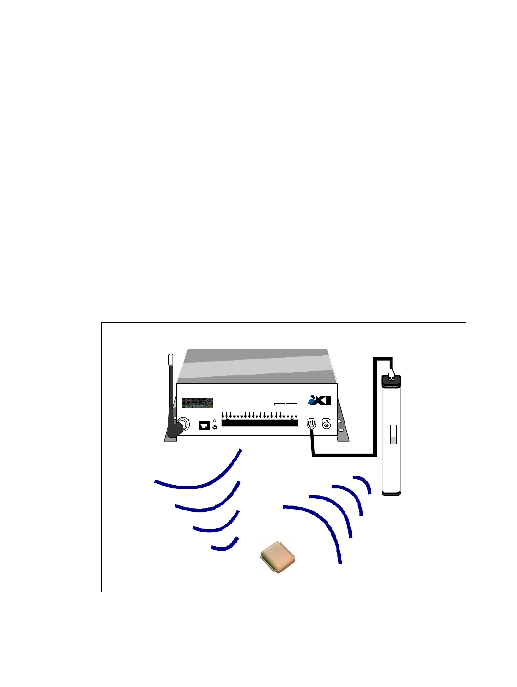
Figure 2 - "Bus" Topology Figure 3 - "Star Topology
Cable capacitance is a large factor in determining the quality of the signal on the network, and EXI rec-
ommends that cables with capacitance of greater than 15 pf per foot should be avoided. The network
should be constructed using a “multi-drop bus” type topology, avoiding any “star” type configuration.
The system is designed to operate with up to 4,000 ft of cable with the recommended topology and ca-
ble. The total cable length varies depending upon the cable capacitance and effective resistance, topol-
ogy, and number of devices on the network. If the estimated total cable length is greater than 4,000 ft, a
RS-485 Repeater will be required to ensure that the system works reliably, or works at all.
It is also recommended that a Repeater be used to isolate HALO Elevator Controllers from the main
system to minimize noise pick-up and loading of the system. Cables used in Elevator shafts should be
stranded and not solid, and should be resilient enough to withstand the continuous flexing that it will
experience for many years in the elevator shaft.
Figure 4 - Typical HALO Configuration
R2 RECEIVER
DATA
COMM.
Made in Canada . . with care
12/24 VDC
GROUND
DATA 0
DATA 1
N/O 1
COM 1
N/C 1
N/O 2
COM 2
N/C 2
1 2 3 4 5 6 7 8 9 10
POWER RELAY
Controller 1
Whip
Antenna Exciter
Antenna
HALO Network
RECEIVE
ANTENNA RBC
FCC ID# HE7MAX
TRANSMIT OUTPUT
SEA #1 SEA #2
Made in Canada . . with care Controller
by
Power
1 2 3 4 5 6 7 8 9 10 11 12 13 14 15 16 17 18 19 20
+24V DC Input
System Ground
+12V Ou 200 ma
System Ground
Weigand 0/Data
Weigand 1/Gnd
System Ground
MagOut 24V 200 ma
Door Switch In
System Ground
Unlock In
Override In
Strobe In
N.O
COM
N.C.
N.O
COM
N.C
Relay #1 Relay #2
Alarm In
OFF ON
EXI ELECTRONIC SYSTEMS
Winnipeg, Manitoba (204) 788-1696
Made in Canada
PRODUCT
MODEL NO.
SERIAL NO>
ROAM II/TAGRRR
SEA-M
1118
Controller 2
Whip
Antenna
Exciter
Antenna
RECEIVE
ANTENNA RBC
FCC ID# HE7MAX
TRANSMIT OUTPUT
SEA #1 SEA #2
Made in Canada . . with care Controller
by
Power
1 2 3 4 5 6 7 8 9 10 11 12 13 14 15 16 17 18 19 20
+24V DC Input
System Ground
+12V Ou 200 ma
System Ground
Weigand 0/Data
Weigand 1/Gnd
System Ground
MagOut 24V 200 ma
Door Switch In
System Ground
Unlock In
Override In
Strobe In
N.O
COM
N.C.
N.O
COM
N.C
Relay #1 Relay #2
Alarm In
OFF ON
Winnipeg, Manitoba (204) 788-1696
Made in Canada
PRODUCT
MODEL NO.SERIAL NO>
ROAM II/TAGRRR
SEA-M
1118
RIM
RIM
Receiver 1
Whip
Antenna
RIM
RS485 Bus
TAP
TAP
TAP
PC
Terminator
RS-485
Repeater Elevator Controller
RIM

EXI HALO Installation Manual Rev 2.0
EXI Wireless Systems Inc. Page 7June, 1999
2.2. CONTROLLER CONFIGURATIONS
The HALO controller handles all communication with the Tags, provides audible and visual indicators
of what state its in and prevents egress when necessary. The controller chassis may be horizontally or
vertically mounted, on a wall, ceiling or shelf and should be mounted so that the front face panel is
easily accessible. Since it is preferable to leave the RX antenna attached directly to the controller, the
exact location of the controller will affect the reception of the tags and should only be finalized after
setting up the field. This device is fully capable of operating in stand-alone mode although it does pro-
vide for communication to several different types of central reporting systems. The front panel provides
easy access to a number of different output formats as well as allowing inputs to alter some of its
automatic functions as necessary. Local alarm and bypass annunciation is available through several dif-
ferent user interface devices. These devices are discussed in more detail in Section 2.4 KEYPAD OR
PINPAD?
The Tag serial numbers as well as status information is output in Weigand format on 2 of the output
pins. This is a standard format used by many Card Access Systems. The MagOut line will engage a
Magnetic Door Lock when Tag’s are detected in the field. Due to NFPA 101 regulations being
adopted in many locations, it may be mandatory to provide an automatic door release with 15 seconds
after a door has been locked up. The controller provides 2 Form-C dry contacts rated at 2 Amps @
30VDC. They switch ON to indicate the 2 different alarm conditions – Tag In Field (TIF) and Tag
Initiated Communication (TIC). These Relays can be used to turn on remote signaling devices such as:
- Nurse Call system annunciators (should have latching function)
- EXI model “SSM” 2-zone audible alarm with selectable tone sequences
- EXI model “ANN-6L” Audible-Visual 6-zone, LED type non-supervised
Annunciator
- EXI model “APEX”, supervised Annunciator system through inputs of
an APEX I/O-8
Contact EXI for more information on each of the above systems and wiring diagrams for many differ-
ent situations.
The Door Switch is used by the HALO controller to disable alarm reporting when the door is closed.
This is known as the Nurse Saver Feature. Although Tags are still detected and reported to a central
system, no alarms are annunciated until the door opens. At that time, all the Tags are re-read by the
controller so that only the Tags that are still in the field will cause an alarm. The door switch is also
useful during bypass as the controller will detect the door opening and then terminate the bypass as
soon as the door closes.
A remote system or switches can use three input lines to alter the normal operation of the controller.
Unlock In provides a temporary release of the door. Alarm in will cause an immediate lockup of the
door with the local and remote alarm annunciators on. Override In will disable the controller so that
no tags are read and nothing will be reported to the Host computer. Shorting the appropriate line to
ground will activate the function.
Please refer to the HALO Controller Operation Manual for a more detailed description of the con-
troller functions.
2.3. LOCATION FOR SRA EXCITER ANTENNAS
The most important aspect of the entire installation is the correct positioning of the SRA Exciter An-
tenna. Take note of the following:
- Ensure that no tag can reach the protected area without passing through a field.
EXI HALO Installation Manual Rev 2.0
EXI Wireless Systems Inc. Page 8June, 1999
- The field should not extend into other rooms or areas that are regularly occupied
by tags. These tags could keep a controller in a pre-alarm state preventing the
door from opening if magnetic door locks are being used.
- The tag should also be detected at least 4 feet from the door in order to give the
magnetic door lock time to energize.
- Proximity to other fields could also be a factor. If a Tag is able to receive com-
munication from 2 different controllers in the case of field overlap, it will try to
respond to both controllers. Each controller will see Tag communication when it
doesn’t expect it and report it as noise.
Ceiling height, door approach width and metal in the vicinity, need to be considered when planning the
location for the exciter antennae. The field should extend to the floor and from wall to wall. A dropped
ceiling consisting of a grid and non-foil backed ceiling tile are the easiest construction materials to
work with. Check above the lay-in tile to see how much space you have and the proximity of metal ob-
jects such as pipes, cables and air plenums. The SRA may also be dropped inside a wall cavity. Some-
times it’s simpler to mount the SRA on the side of a wall above the door or along the hallway about 5
feet from the floor.
Extensive metal close to the Exciter can distort the field in unpredictable ways. Metallic objects will
absorb and/or reflect radiated energy, which affects the field. This phenomenon can increase or decrease
the field strength in areas causing hot spots or holes in your field. It can even change the shape of the
field with tag detection sometimes occurring as much as 35 ft away. At times this effect can be used to
advantage but the desired result can only be determined experimentally.
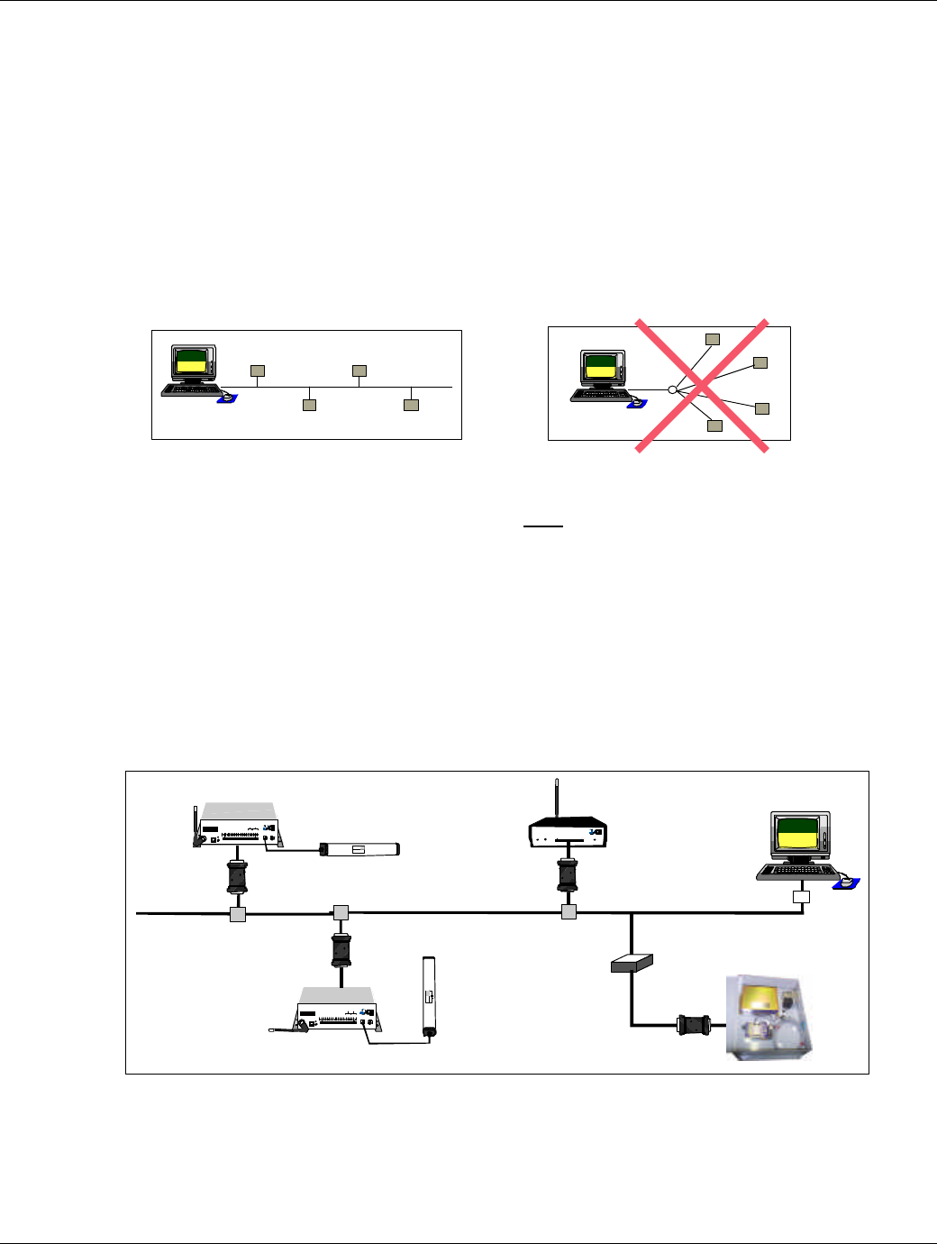
Although it is not possible to completely predict the performance of the field for every situation, some
information about the field will help to shorten the process of determining the best location for the
SRA. In the absence of any site irregularities, the field is symmetrical perpendicular to the antenna
length. A cross-section through the length of the antenna is roughly oval as shown below.
Figure 5 – Antenna Field
Although the field strength is adjustable, the maximum distance for good coverage is approximately 10
feet. Sometimes 2 exciters are necessary to get adequate coverage.
The location of the SRA is limited only by your imagination. If you have a location where you would
like to mount it, try it. If it doesn’t work, try something else. The important thing is that it must work
well in its location. Each field needs to be fully tested to ensure adequate coverage of the protected
If it’s not possible to create a proper field with the exciter
inside, an SRA-E exciter antennae for outdoors could be
placed on an outside wall to limit the penetration of the
field into the building.

EXI HALO Installation Manual Rev 2.0
EXI Wireless Systems Inc. Page 9June, 1999
area. The procedure to fully test the field is described in the “INSTALLING CONTROLLERS” sec-
tion of this manual.
2.4. KEYPAD OR PINPAD?
Each of the user interface devices provide local audible and visual alarm and bypass indication as well
as a means for the user to input requests to the system. If a staff member needs to be able to inititiate a
bypass function from either side of the door, there will have to be two user interface devices of the
same type installed. The type of device to select is dependent upon the situation and the user require-
ments.
KEYPAD – different codes for bypass and reset – everybody uses the same codes
PINPAD – different codes for bypass and reset – everybody has their own codes
2.5. LOCATING THE RECEIVER ANTENNA
The area to be protected has to be blanketed by controllers and receivers so that all critical areas have
coverage. Elevator Interfaces cannot be included in the area calculations since the elevator is not al-
ways on the floor. Walls, equipment and excess metal could affect the pickup range. Although greater
distances are possible, a maximum of 50’between devices is recommended.
It is essential that the RX antennas have no metal barriers blocking the signals from the Tags although
some metal objects may enhance communication by reflecting the signal further than it would normally
transmit. Wire glass sometimes found around nurseries can cut down the range. The only way to be
sure of adequate coverage is by testing the results. After all devices are installed and operational, en-
sure that the entire area has coverage. Experience will shorten this process as the installer learns what
site conditions cause problems.
One of the issues to think about is the storage and handling of the tags when not on the patients. Tags
that are not on a “body” or stored in a proper container are periodically transmitting TIC alarms. Un-
necessary alarms can occur while cleaning Tags and when transferring a Tag to or from a patient. The
Host computer software allows the staff to put the Tag into a special status so that it will ignore all
TIC alarms coming from that Tag. However, any equipment driven by the relay outputs of the devices
will still be triggered and the staff also has to remember to put the Tag back into active status when
done. It is best to avoid the problem if at all possible.
Cleaning of the Tags could be done in a room that is outside the range of any devices. The staff may
prefer to bring a patient to a particular room to put on a Tag and then remove the Tag at the door as
they walk the patient out. The site administration people should be consulted about these issues prior
to installing the system
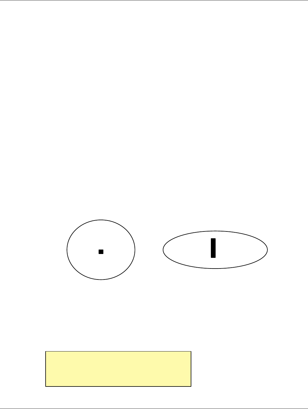
Watch out for foil backed ceil-
ing tile.
EXI HALO Installation Manual Rev 2.0
EXI Wireless Systems Inc. Page 10 June, 1999
3. INSTALLATION PROCEDURES
3.1. INSTALLING CONTROLLERS
3.1.1. PREPARE CONTROLLER FOR FIELD SET UP
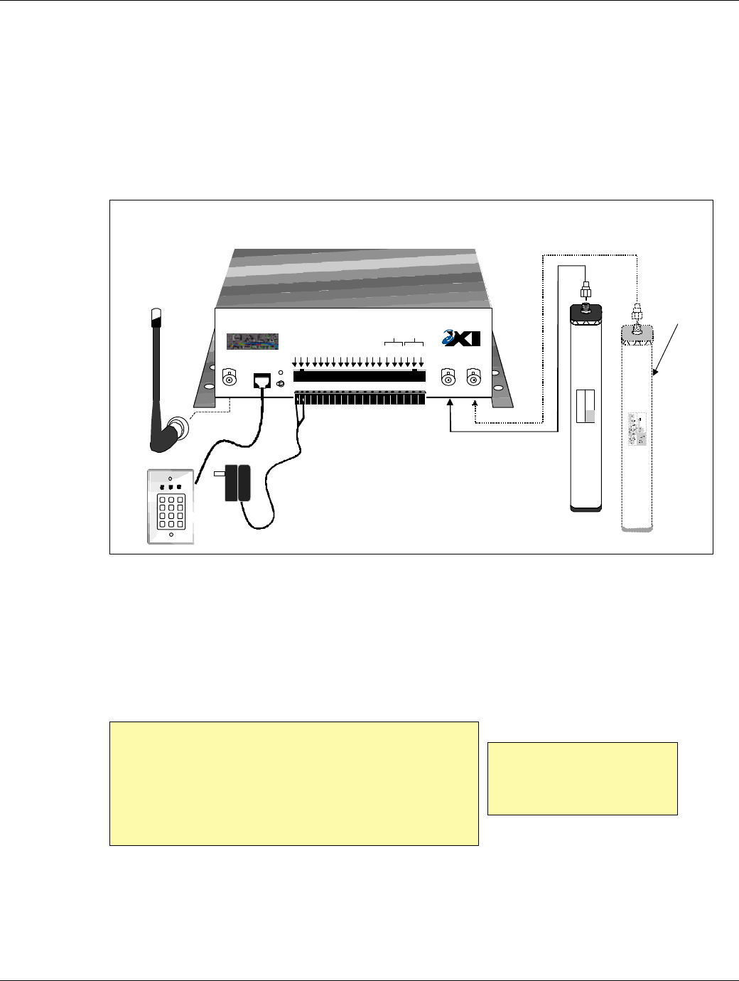
Figure 6 - HALO Controller Typical Hook-up Diagram
Assemble the controller pieces as illustrated in the above diagram. This is only a preliminary assembly
in order to set up the field. If necessary, obtain an AC extension cord so that the system may be tempo-
rarily energized at this location. Connect a user interface device such as a DKX Keypad. Make sure the
jumper on the back is in the maximum volume position so you can hear the beeper from a distance.
Check inside the controller to insure that the proper voltage is selected for the device you want to use.
PinPads use 5V while the Keypad requires 13V.
Install the RX antenna onto the Controller and plug in the R2-SRA. Try to place the RX antenna in the
approximate final location so that the test will be realistic. Open the controller cover and turn the ro-
tary Mode switch to position 0 for Test mode. In this mode the controller will turn on the beeper each
time it successfully reads a Tag. Connect the power supply and power-up. The frequency of beeping
will tell you how good the reception is.
Duct tape is metallic and
should never be used on the
SRA Exciter Antennae
The RX antennas can also be installed on a length of
coaxial cable when the best position for the antenna
is different than the best placement for the device.
The RX antenna should be oriented in the horizontal
plane with the maximum surface of the antenna ex-
posed to the longest distance requirement.
EXI ELECTRONIC SYSTEMS
Winnipeg, Manitoba (204) 788-1696
Made in Canada
PRODUCT
MODEL NO.
SERIAL NO>
ROAM II/TAGRRR
SEA-M
1118
"RX" Antenna
Keypad "SRA"
Exciter Antenna
HALO "Controller"
1 2 3
4 5 6
7 8 9
*0#
Optional, to
Enhamce
Coverage
RECEIVE
ANTENNA RBC
FCC ID# HE7MAX
TRANSMIT OUTPUT
SEA #1 SEA #2
Made in Canada . . with care Controller
by
Power
1 2 3 4 5 6 7 8 9 10 11 12 13 14 15 16 17 18 19 20
+24V DC Input
System Ground
+12V Ou 200 ma
System Ground
Weigand 0/Data
Weigand 1/Gnd
System Ground
MagOut 24V 200 ma
Door Switch In
System Ground
Unlock In
Override In
Strobe In
N.O
COM
N.C.
N.O
COM
N.C
Relay #1 Relay #2
Alarm In
OFF ON
EXI HALO Installation Manual Rev 2.0
EXI Wireless Systems Inc. Page 11 June, 1999
3.1.2. TEST CONTROLLER AND SET UP FIELDS
After reading Section 3.2 on LOCATION FOR SEA EXCITER ANTENNAS, choose a suitable
location for the SRA. Setting up a field is a matter of trial and error. The primary considerations
here are the field shape and strength. The field has to fill the area in front of the door all the way to
the floor so that no tag can reach the door without being detected.
To set up a field, start by placing the tag at the range you want for the field at the height a tag is
usually going to be found. The tag needs to be detected far enough from the door to allow the
magnetic door lock time to energize. The tag should be placed on a non-metallic surface for test-
ing. You might want to do a preliminary field setup by holding the SRA at the approximate loca-
tion you want to install it but be aware that your body could be affecting the field. The SRA should
be temporarily placed and the field adjusted for range using this stationary tag. Since the Tag will
be read easier in some orientations with respect to the SRA, it is also necessary to test with the Tag
in a variety of positions.
With the SRA and tag in position use the SRA RANGE ADJUST control on the top right corner of
the controller circuit board to set up your field strength. Turn the control shaft clockwise all the
way to the end for maximum field range. If the device is not beeping at this point, the SRA will
need to be repositioned. Once the SRA is positioned so that the device is beeping, turn the control
shaft counter clockwise slowly until the beeping stops. Then return clockwise approximately 1/16
of a turn or so that the beeping resumes. Repeat this process for various orientations of the Tag.
Make sure the Tag can be read in any position.
Now that the field range is set up, you need to determine the shape and consistency of the field.
SOME NOTES ON SENSITIVITY: All radio frequency (RF) devices are sensitive to po-
larization. Everyone has had a portable radio that got much louder if it was positioned at a
particular angle. Another example is the TV antenna on your house. If you turned your TV
antenna on it’s side, you would receive a weaker signal and the deterioration of picture
quality would be dramatic if the TV signal you received was already marginal.
Unfortunately all other RF receivers suffer from the same electronic phenomenon. The
Roam II Tag has to first receive from the controller before it will transmit its serial number.
We can expect that there will be better response from the tag in one orientation. A strong
field will ensure that even an improperly oriented Tag will respond.
The most important aspect of the entire installation is the correct positioning of the
SRA Exciter Antenna. A little time spent here will save countless hours of frustration
and service calls later.
Apply double-backed foam tape to the side of the antenna to temporarily attach it to a
vertical surface for testing purposes. Take care that the antenna doesn’t fall as sudden
hard jolts may render it useless.
EXI HALO Installation Manual Rev 2.0
EXI Wireless Systems Inc. Page 12 June, 1999
TROUBLESHOOTING: If the controller is having trouble detecting tags, try different
positions for the RX antenna. Raising the detection THRESHOLD with the rotary switch on
the far left of the controller circuit board can remove some of the background noise as well as
reduce interference from Tags talking to nearby controllers.
Holding the tag in a closed fist, pass the Tag slowly through all the areas that you need the field to
cover twisting your wrist back and forth slowly as you move. DON”T FORGET DOWN BY
THE FLOOR. The device should continue to beep at a steady rate. An uneven rate indicates that
the controller is not able to read the tag successfully every time. The final step is to ensure that the
field does not extend into other rooms or areas that are regularly occupied by tags. These tags
could inadvertently keep a controller in an alarm state.
3.1.3. FINALIZE CONTROLLER INSTALLATION
Fasten SRA exciter antenna. If installing the SRA above a ceiling tile, use a marker pen to draw an
outline of the SRA in its desired position on the upper side of the tile. Once you are certain of the
SRA location, use a small amount of “Liquid Nail”, “Firestone 500”, silicone caulk, or similar
product to cement the SRA to the tile, preventing it from falling on the floor should the tile be
lifted for any reason.
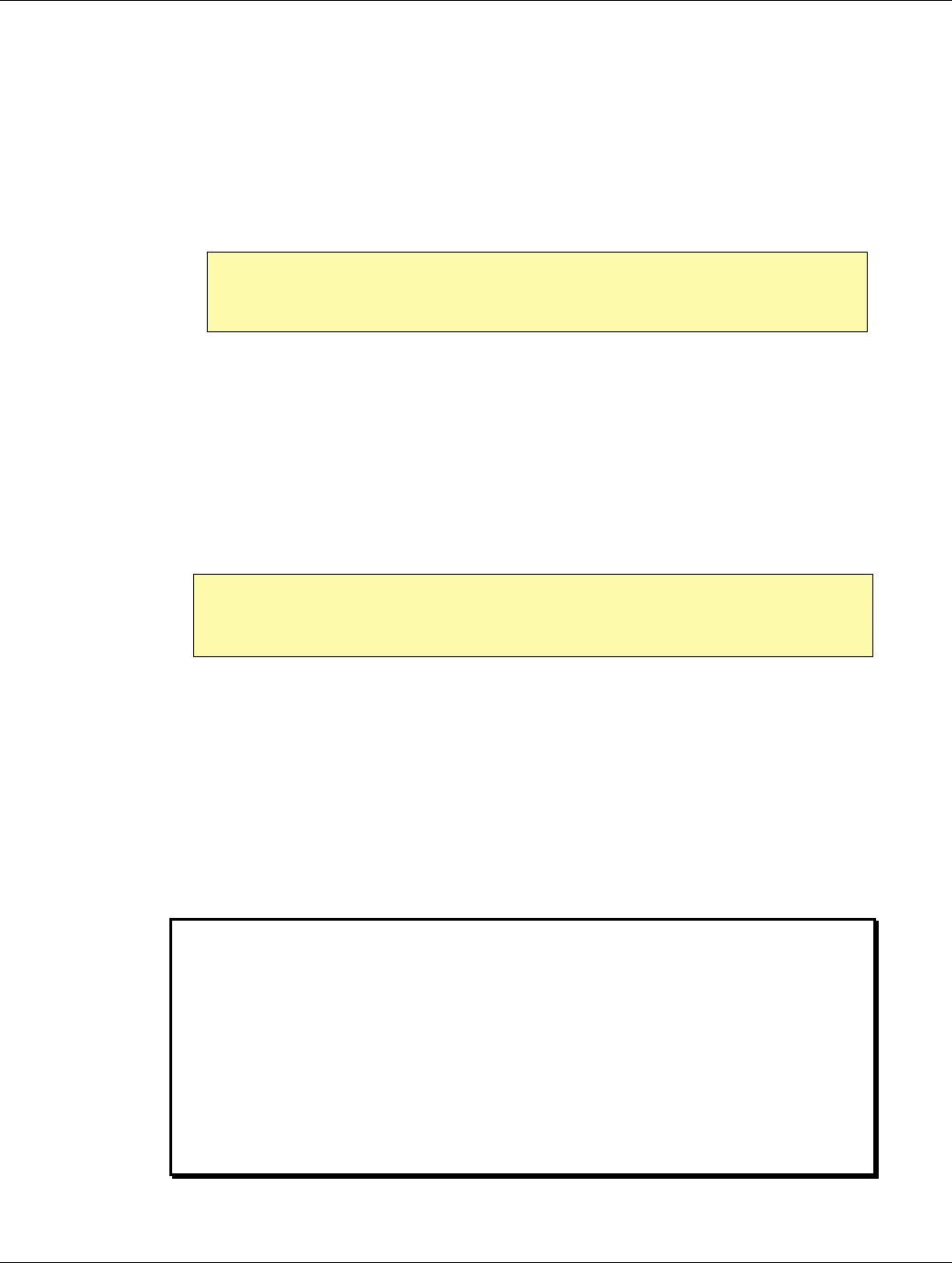
If the SRA is to be dropped inside a wall cavity, do not let it hang on the coax cable nor hang so
low that it touches the bottom steel plate. Loop the coax cable and wrap a band of electrical tape
around it as shown below. Ensure the SRA will hang at the correct height by marking the cable
prior to dropping the SRA inside the wall. Secure the cable when the SRA is hanging in the correct
position.
Figure 7 - Securing the Exciter Antenna Cable
Mount the Controller permanently and position the RX antenna. Mount the user interface device(s)
where planned
The DKX and the PINPAD panels are designed for flush wall mounting in a standard 2-gang elec-
trical box. Should surface mounting be necessary, an optional SMB box is available. Adjust the
sound level for the beeper by moving the jumper on the back of the panel to the next set of pins
until the desired sound level is achieved. Should a louder local alarm be desired, either use a Wire-
mold box extension and break out the knock out holes before mounting the panel, or remove the
Piezo and relocate it above the ceiling so the Piezo opening has a direct path into the corridor.
The Keypad installation is similar to the above except it only needs a 1-gang electrical box. Also,
there is no volume control for the beeper on the Keypad.
Install door switch. Hook up Maglock and any peripheral devices. Make sure the Maglock will re-
lease in case of a Fire Alarm.
Power up and test the field again.
EXI ELECTRONIC SYSTEMS
Winnipeg, Manitoba (204) 788-1696
Made in Canada
PRODUCT
MODEL NO.
SERIAL NO>
ROAM II/TAGRRR
SEA-M
1118
EXI HALO Installation Manual Rev 2.0
EXI Wireless Systems Inc. Page 13 June, 1999
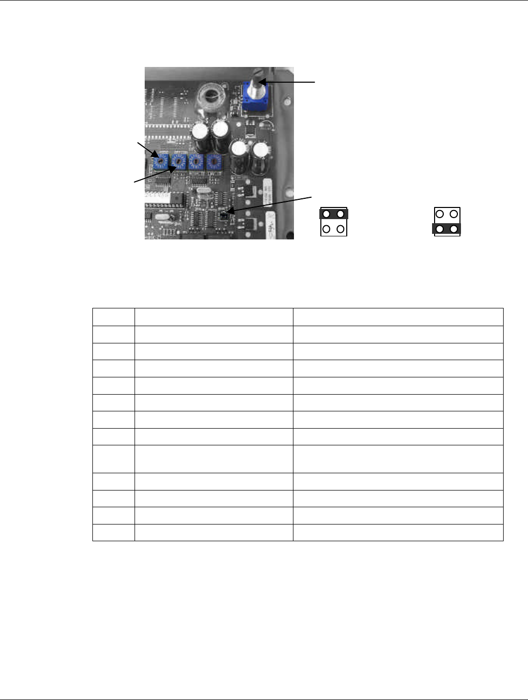
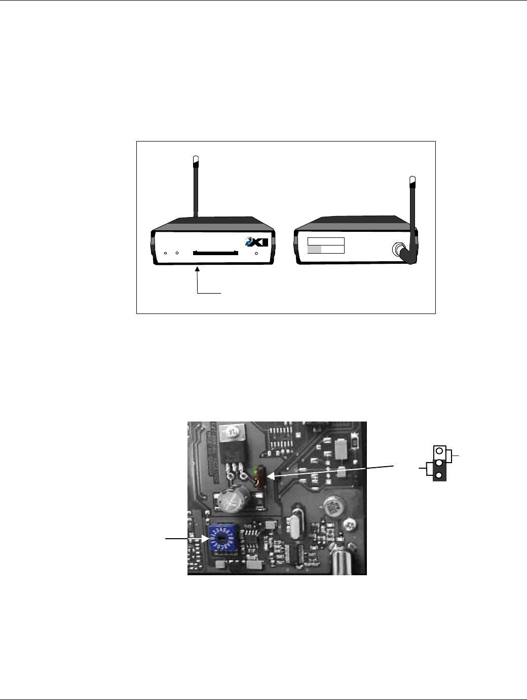
3.1.4. SET CONTROLLER SWITCHES FOR NORMAL OPERATION
Flip open the Controller lid to set the switches inside for the desired operation.
Figure 8 – Controller Switch Identification
MODE SWITCH SETTING
Change switches to desired operating mode as outlined below.
Mode Controller Function Response
0Test Mode
1Patient Monitoring with DKX Alarm ends on its own – fixed maximum bypass time
2Patient Monitoring with DKX Continuous alarm - fixed maximum bypass time
3Patient Monitoring Alarm ends on its own – fixed maximum bypass time
4Patient Monitoring Continuous alarm - fixed maximum bypass time
5Article Surveillance – Protection Alarm ends on its own – bypass extended by new tag
6Article Surveillance – Protection Continuous alarm - bypass extended by new tag
7, 8, 9 Reserved for Article Surveillance -
Monitoring
AAuthorized Entry 4 second release
BAuthorized Entry 8 second release
CAuthorized Entry Keep released while tag in field
D,E,F No Function
Modes 1 and 2 will only allow Bypass when the field is clear of Tags and the user enters a se-
quence of key presses on the DKX as described in the HALO Operation Manual. Keypads are for
Article Surveillance and Patient Monitoring Modes 3 and 4. The Pinpad can be used with any of
the Modes.
OPTION SWITCH SETTING
“Mode”
“Option”
Switch
“Range Adjust”
J2: Relay function
1
2
Relay 1 = TIF
Relay 2 = TIC 1
2Both TIF

EXI HALO Installation Manual Rev 2.0
EXI Wireless Systems Inc. Page 14 June, 1999
With a HOST computer in the system, the recommended switch setting for the “Authorized Entry”
mode is Option 0 (No Tags are authorized). “Patient Monitoring” or “Article Surveillance”
modes should have Option 1 selected (All Tags will be stopped).
These settings let the HOST have complete control over which Tags are allowed access to or from
the protected areas. The following table shows the selected function for each switch position, de-
pending on the mode selected.
Digit Selection Structure: Tag Serial # consists of digits ABCDEF
Option
Switch Function Patient Monitoring or
Article Surveillance Authorized Entry
0Don’t act on any Tags No Tags are stopped No Tags authorized
1Act on all Tags All Tags will be stopped All Tags authorized
2Tag Selection on digit A Selected Tags will be
stopped Selected Tags authorized. -
“no tag” + door open =
alarm
3Tag Selection on digit B Selected Tags will be
stopped Selected Tags authorized. -
“no tag” + door open =
alarm
4Tag Selection on digit C Selected Tags will be
stopped Selected Tags authorized. -
“no tag” + door open =
alarm
5Tag Selection on digit D Selected Tags will be
stopped Selected Tags authorized. -
“no tag” + door open =
alarm
6Tag Selection on digit E Selected Tags will be
stopped Selected Tags authorized. -
“no tag” + door open =
alarm
7Tag Selection on digit F Selected Tags will be
stopped Selected Tags authorized. -
“no tag” + door open =
alarm
8Tag Selection on digit A Select Tags allowed to
pass Selected Tags authorized. -
“no tag” + door open is OK
9Tag Selection on digit B Select Tags allowed to
pass Selected Tags authorized. -
“no tag” + door open is OK
ATag Selection on digit C Select Tags allowed to
pass Selected Tags authorized. -
“no tag” + door open is OK
BTag Selection on digit D Select Tags allowed to
pass Selected Tags authorized. -
“no tag” + door open is OK
CTag Selection on digit E Select Tags allowed to
pass Selected Tags authorized. -
“no tag” + door open is OK
DTag Selection on digit F Select Tags allowed to
pass Selected Tags authorized. -
“no tag” + door open is OK
E, F No Option
RANGE SWITCH SETTING:
EXI HALO Installation Manual Rev 2.0
EXI Wireless Systems Inc. Page 15 June, 1999
If HIGH ID > LOW ID, all Tags with digit x equal to or between the 2 numbers are selected
If HIGH ID < LOW ID, all Tags with digit x greater than or equal to LOW are selected
and all Tags with digit x less than or equal to HIGH are selected
If HIGH ID = LOW ID, only Tags with digit x = to HIGH or LOW are selected
3.2. INSTALL RECEIVERS
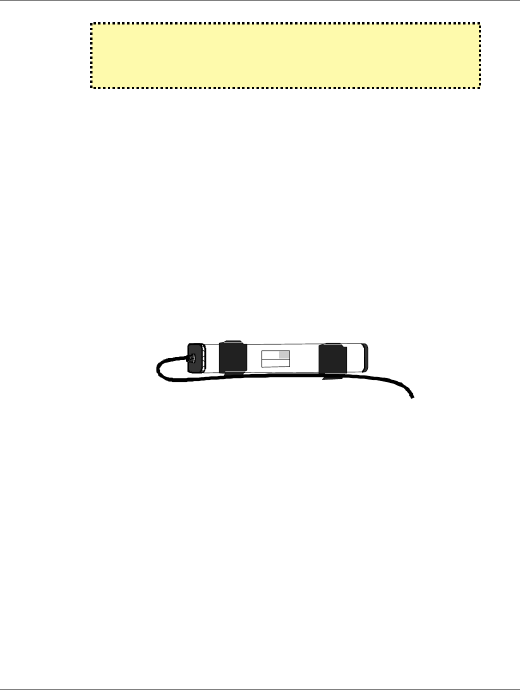
Figure 9 – HALO Receiver
Receivers are meant for use where only a “TIC” signal needs to be detected. The “Relay” light
comes on to indicate relay activation when a “TIC” is detected. Receivers are not capable of cre-
ating a field of energy using Exciters, as Controllers can, and therefore do not have to be con-
nected to the Exciter Antennae. Install the RX Antenna onto the Receiver, place the Receiver in the
approximate location for final use, connect the power supply and power-up. Adjust the RX An-
tenna orientation for the best reception.
Figure 10 – HALO Receiver Threshold and Operating Voltage Setting
3.3. TESTING TIC ALARM COVERAGE AROUND THE BUILDING
With all devices installed at the location, ensure that a “TIC” can be detected from all remote corners
and locations of the protected area. Also ensure that the overlapping fields of detection from the vari-
ous Controller and Receiver devices are fine-tuned.
"RX" Antenna
12/24 V DC
HALO "Receiver"
R2 RECEIVER
DATA
COMM.
Made in Canada . . with care
12/24 VDC
GROUND
DATA 0
DATA 1
N/O 1
COM 1
N/C 1
N/O 2
COM 2
N/C 2
1 2 3 4 5 6 7 8 9 10
POWER RELAY
EXI ELECTRONIC SYSTEMS
Winnipeg, Manitoba (204) 788-1696
Made in Canada
PRODUCT
MODEL NO.
SERIAL NO>
ROAM II/TAGRRR
RECEIVER
1119
RECEIVER
ANTENNA
Back ViewFront View
“Threshold”
Switch
12
24
EXI HALO Installation Manual Rev 2.0
EXI Wireless Systems Inc. Page 16 June, 1999
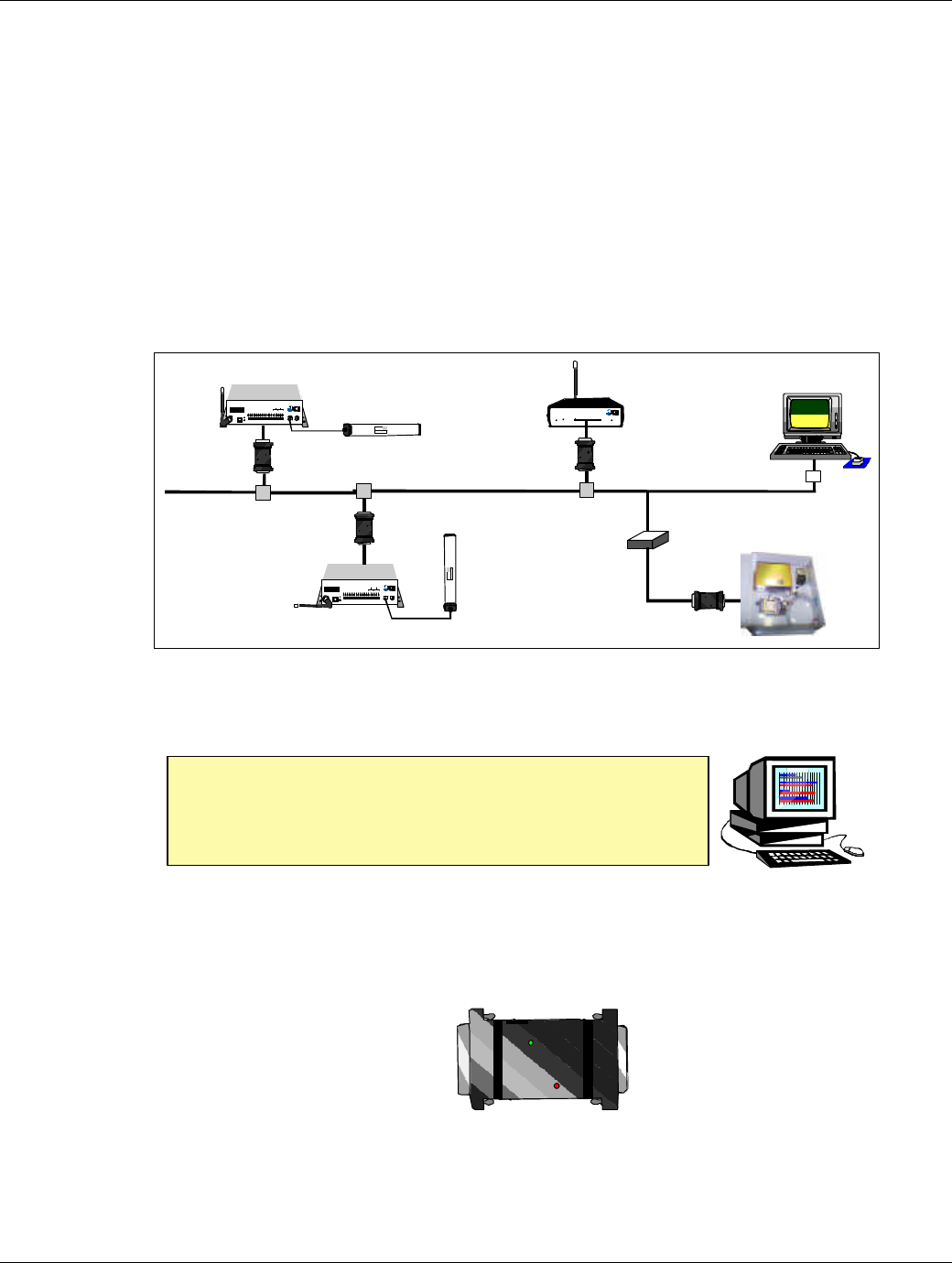
3.4. CONNECTING TO THE HOST COMPUTER
The Host Computer is included in a full-blown HALO system that needs central site monitoring and
control. The Host Computer runs the HALO Application Software that provides the following major
functions:
§ Management of the database that stores the identities of all the system components and Tags that
are deployed within the system
§ Management and storage of logs of all the alarm conditions that occur during use
§ Annunciation of any of the alarm conditions that may exist, showing location of such an alarm
condition in a graphical format overlaid over the floor plan of the building in which the system is
installed
Figure 11 – HALO Network with Host Computer
For HALO systems that only require localized alarm and control, the Host Computer may not be re-
uired.
All devices on the RS485 bus will require an RIM for Weigand to RS485 conversion. It is important
for the computer RS485 output be connected to the “PC Terminator”, and not directly to the RS485
network so as to provide the correct termination and loading required for the driver within the PC. The
R2 TAP boxes may be used to provide clean connections from the RIM to the RS485 network line.
Figure 12 – Sketch of RIM
The Host Computer consists of a Pentium based computer with a 17”
Color Monitor, a Keyboard, mouse, and Speakers for audible feed-
back. A ZIP drive is used for periodic, data backup. The ZIP disk is
removable, allowing for off-site archiving of the backed-up database.
R2 RECEIVER
DATA
COMM.
Made in Canada . . with care
12/24 VDC
GROUND
DATA 0
DATA 1
N/O 1
COM 1
N/C 1
N/O 2
COM 2
N/C 2
1 2 3 4 5 6 7 8 9 10
POWER RELAY
Controller 1
Whip
Antenna Exciter
Antenna
HALO Network
RECEIVE
ANTENNA RBC
FCC ID# HE7MAX
TRANSMIT OUTPUT
SEA #1 SEA #2
Made in Canada . . with care Controller
by
Power
1 2 3 4 5 6 7 8 9 10 11 12 13 14 15 16 17 18 19 20
+24V DC Input
System Ground
+12V Ou 200 ma
System Ground
Weigand 0/Data
Weigand 1/Gnd
System Ground
MagOut 24V 200 ma
Door Switch In
System Ground
Unlock In
Override In
Strobe In
N.O
COM
N.C.
N.O
COM
N.C
Relay #1 Relay #2
Alarm In
OFF ON
EXI ELECTRONIC SYSTEMS
Winnipeg, Manitoba (204) 788-1696
Made in Canada
PRODUCT
MODEL NO.
SERIAL NO>
ROAM II/TAGRRR
SEA-M
1118
Controller 2
Whip
Antenna
Exciter
Antenna
RECEIVE
ANTENNA RBC
FCC ID# HE7MAX
TRANSMIT OUTPUT
SEA #1 SEA #2
Made in Canada . . with care Controller
by
Power
1 2 3 4 5 6 7 8 9 10 11 12 13 14 15 16 17 18 19 20
+24V DC Input
System Ground
+12V Ou 200 ma
System Ground
Weigand 0/Data
Weigand 1/Gnd
System Ground
MagOut 24V 200 ma
Door Switch In
System Ground
Unlock In
Override In
Strobe In
N.O
COM
N.C.
N.O
COM
N.C
Relay #1 Relay #2
Alarm In
OFF ON
Winnipeg, Manitoba (204) 788-1696
Made in Canada
PRODUCT
MODEL NO.
SERIAL NO>
ROAM II/TAGRRR
SEA-M
1118
RIM
RIM
Receiver 1
Whip
Antenna
RIM
RS485 Bus
TAP
TAP
TAP
PC
Terminator
RS-485
Repeater
Elevator Controller
RIM
EXI HALO Installation Manual Rev 2.0
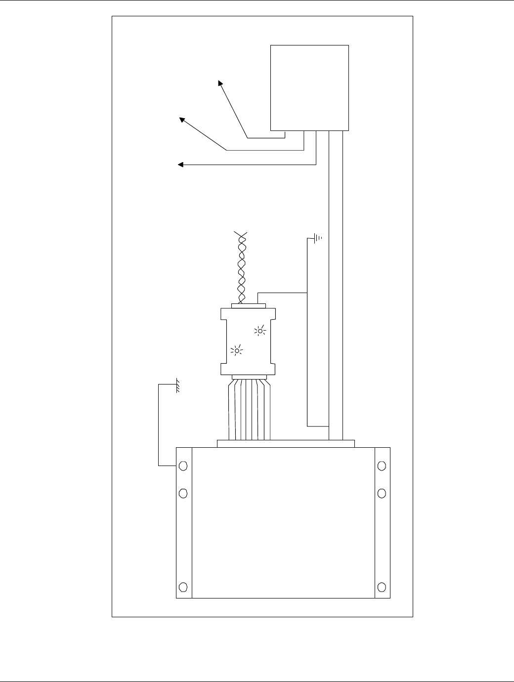
EXI Wireless Systems Inc. Page 17 June, 1999
Figure 13 – HALO System Grounding
Controller
(Top View)
Device 1 Central
Power
Supply
CPS-24
To
Device 2 To
Device 3
To
Device N
- RS485
- RS485
AWG14 (Ground) which runs
through entire ROAM II Network
-
+
20-pin
Connector
Building
Ground
RIM
EXI HALO Installation Manual Rev 2.0
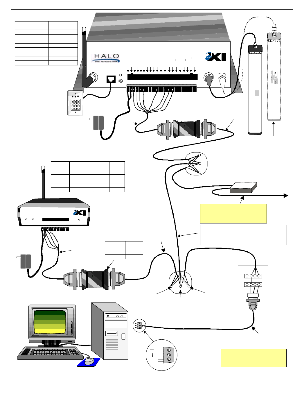
EXI Wireless Systems Inc. Page 18 June, 1999
Figure 14 - Halo Wiring Diagram
RECEIVE
ANTENNA RBC
FCC ID# HE7MAX
TRANSMIT OUTPUT
SEA #1 SEA #2
Made in Canada . . with care Controller
by
Power
1 2 3 4 5 6 7 8 9 10 11 12 13 14 15 16 17 18 19 20
+24V DC Input
System Ground
+12V Out 200 ma
System Ground
Weigand 0/Data
Weigand 1/Gnd
System Ground
MagOut 24V 200 ma
Door Switch In
System Ground
Unlock In
Override In
Strobe In
N.O
COM
N.C.
N.O
COM
N.C
Relay #1 Relay #2
Alarm In
OFF ON
RS+
RS-
GND
RS+
RS-
GND
R2 RECEIVER
DATA
COMM.
Made in Canada . . with care
12/24 VDC
GROUND
DATA 0
DATA 1
N/O 1
COM 1
N/C 1
N/O 2
COM 2
N/C 2
POWER RELAY
1 2 3 4 5 6 7 8 9 10
DKX
Keypad
Optional
PS-24
Power
Supply
EXI ELECTRONIC SYSTEMS
Winnipeg, Manitoba (204) 788-1696
Made in Canada
PRODUCT
MODEL NO.
SERIAL NO>
ROAM II/TAGRRR
SEA-M
1118
Brn
RIM
Grn
Blk
Blu
Whi
Red
Yel
Gry
1 2 3
4 5 6
7 8 9
*0#
Grn
Blk
Blu
RIM
R2 TAP
PC Terminator
Box
PC to
Network Cable
RS-485Weigand
Brn
Pin# Wire
Color Function
3Brown +12/24 V
4Green System GND
5Black Weigand 0/Data
6Blue Weigand 1/Data
10 White Alarm In
12 Red Unlock In
13 Yellow Override In
14 Gray Strobe In
Factory
Wired
Factory
Wired
RS-485 Shielded Cable, 24 AWG
Maximum Capacitance 15 pf per foot
Example: Electro Cables FT-4 Part #5302452
Daisy Chain (Series) Configuration as much as
possible.
RS-485 Connector (To Halo
NetworkController Output)
DB9
R2
Receiver
Pin
Function Wire
Color DB 25
1+12/24V Brown 14
2System GND Green 7
3Data 0 Black 20
4Data 1 Blue 22
TAP
Optional
PS-24
Power
Supply
Pin # Function
9 or 12 RS +
7GND
22 or 25 RS -
RIM Pin-Out
Com
NOTE: Check all network
wiring before connecting
to the PC.
Enlarged
View
RS +
(Yellow) Gnd
(Green)
RS -
(White)
Caution: Ensure appropriate
stranded cables are used for
Elevator Shafts due to the
continuous flexing they will
have to endure!
Factory
Supplied
Factory
Supplied
RS-485Weigand
Factory
Supplied
Optional RS-485 Repeater
(Required for total cable length
of greater than 4,000 ft, and
highly recommended for isolation
of Halo Elevator Controller)
RS-485
Repeater
Halo Receiver Connector Pin-Out
Halo Controller Connector Pin-Out
Optional, to
Enhamce
Coverage
Elevator System or
other devices

EXI HALO Installation Manual Rev 2.0
EXI Wireless Systems Inc. Page 19 June, 1999
4. Weigand Output Specification
Fields # of bits
Even Parity bit (first)1 Parity bit + next 16 bits = 0
Control code 4used to distinguish message types
Door bit 11 = Door open, 0 = Door closed
Maglock bit 11 = Maglock On, 0 = Maglock off
Info - 1 8Info bytes are dependant on message type (see below for descriptions)
Info- 2 8 either bit patterns bit 7 -> bit 0
Info - 3 8 or 6 digits (1 digit = 4 bits)
Odd Parity bit (last)1 Parity bit + previous 16 bits = 1
Total 32
The control code that accompanies Tag serial #’s not only identifies that this message contains a Tag serial
# but it also describes the state of the controller at the time.
Message Types Control Code
Decimal (Binary) Info - 1 Info - 2 Info - 3
Tag Serial # -ABCDEF Tag digits - AB Tag digits - CD Tag digits - EF
- normal 0 (0000) “ “ “
- Bypassed 4 (0100) “ “ “
- TIF alarm 1 (0001) “ “ “
- Loiter 3 (0011) “ “ “
- Host alarm 2 (0010) “ “ “
- Unlock Req 5 (0101) “ “ “
- TIC 7 (0111) “ “ “
- Test Mode 10 (1010) “ “ “
PIN # Entry
0 = no key, A = zero key 8 (1000) eg. 4 Key presses
0 (0000) 0 (0000) “0123”
A(1010) 1(0001) 2(0010) 3(0011)
Event (elevator only) 9 (1001) Door Opened = 00 00 01
Switch Selections 11 (1011) Version # Mode/Option ID Range
High/Low
Status - sent after any
significant changes 12 (1100) Noise Counter Input states Device Status
Status message information definition:
Noise Counter - indicates the number of times the device has detected something on its receiver but
couldn’t make sense of it. This counter decrements over time if noise goes away. The status message gets
sent for a Noise Alarm ON (when this counter rolls over to 100(64Hex)) and then again when the Noise
Alarm Clears (gets back to zero).
Device Status - Normal (nothing happening) = 00
bit 7 - not used
bit 6 - RF field occupied by tag(s)
bit 5 - In Override
bit 4 - In Unlock
bit 3 - In Bypass
bit 2 - Host alarm
bit 1 - TIC Alarm
bit 0 - TIF alarm
Input states - nothing “on” will equal 73Hex
bit 7 - not used
bit 6 - Strobe 0 = ignore other host inputs
bit 5 - Override 0 - override request
bit 4 - Unlock 0 = lock release request
bit 3 - bypass key 1 = pressed
bit 2 - Reset key 1 = pressed
bit 1 - Alarm 0 = Host alarm request
bit 0 - Door switch 1 = open, 0 = closed

EXI HALO Installation Manual Rev 2.0
EXI Wireless Systems Inc. Page 20 June, 1999
© Copyright 1999, EXI Wireless Systems Inc. All rights reserved.