Xmark R3C R3 CONTROLLER User Manual Manual R2
Xmark Corporation R3 CONTROLLER Manual R2
UserManual.wiki
>
Xmark
>
R3C User Manual
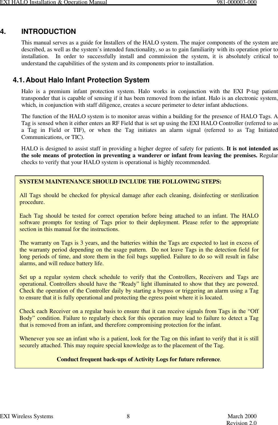
Installation and Operations Manual
Navigation menu
Upload a User Manual
Namespaces
Wiki Guide
HTML
PDF
Info
Views
User Manual
Discussion / Help
Navigation

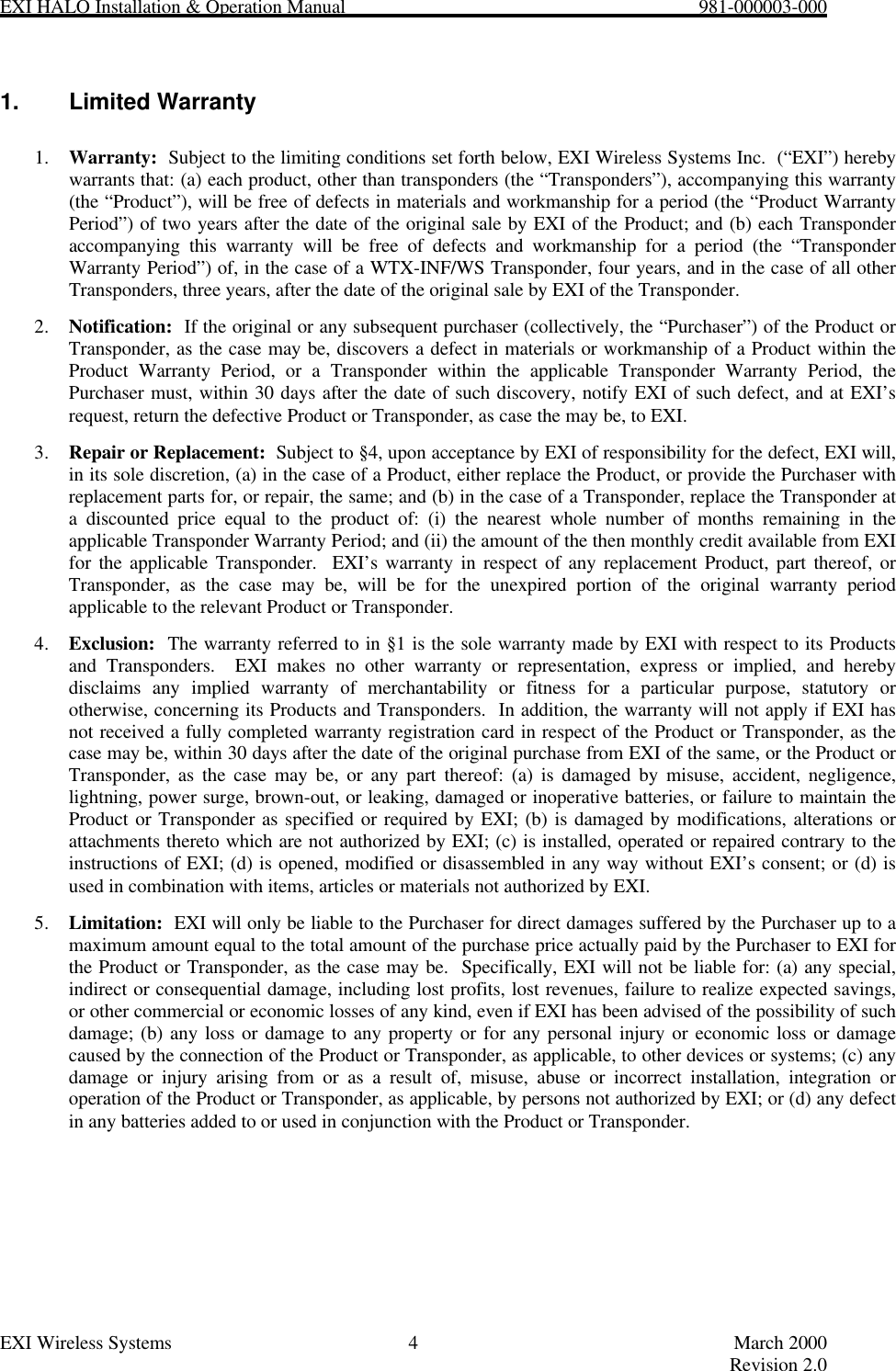
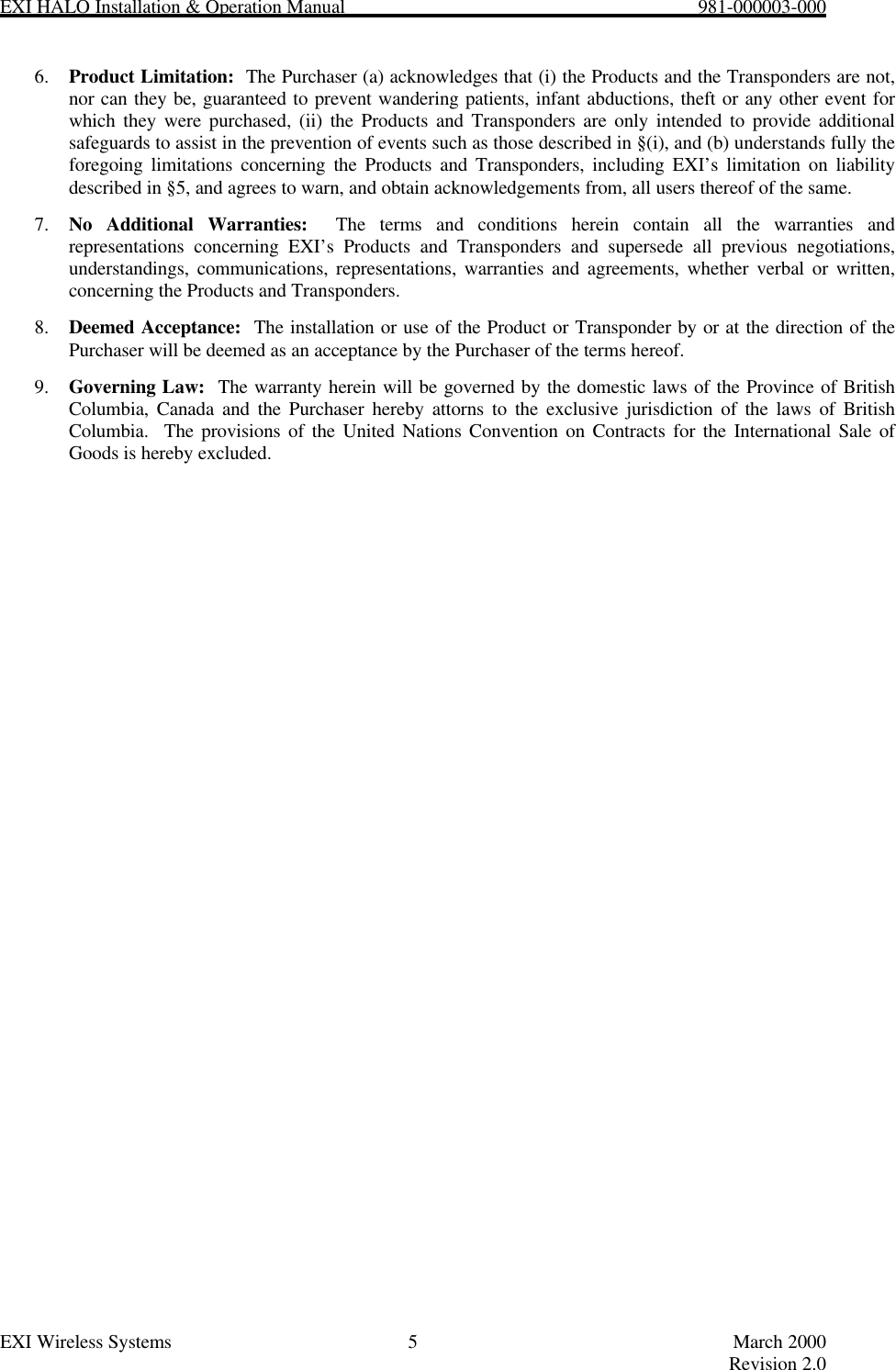
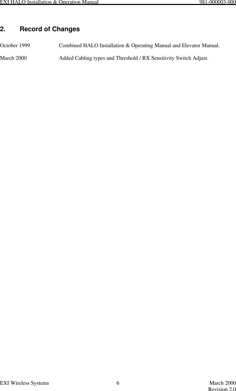
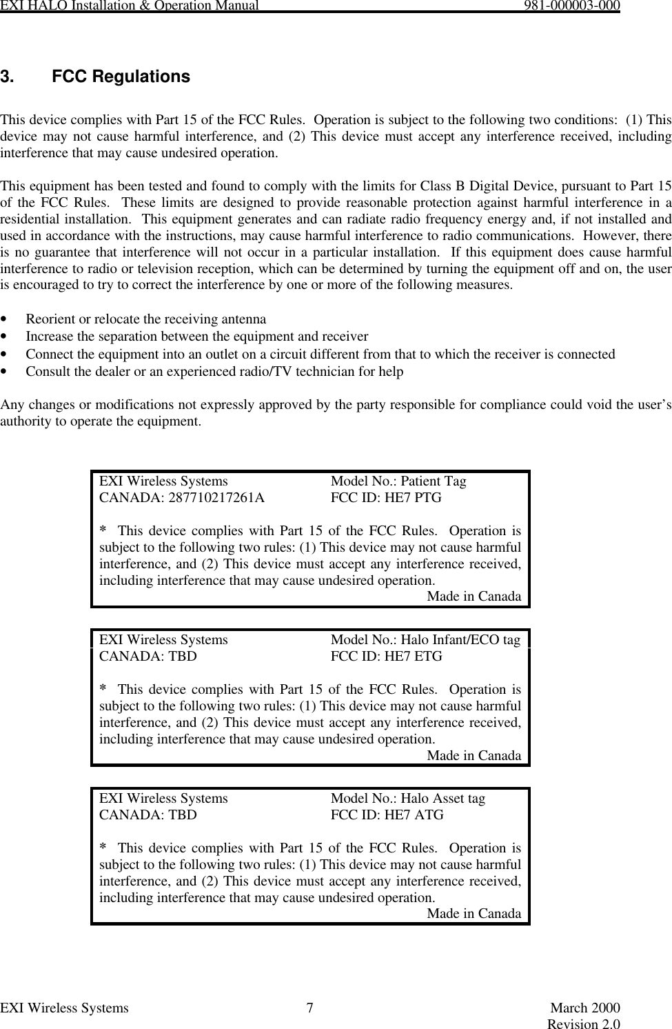

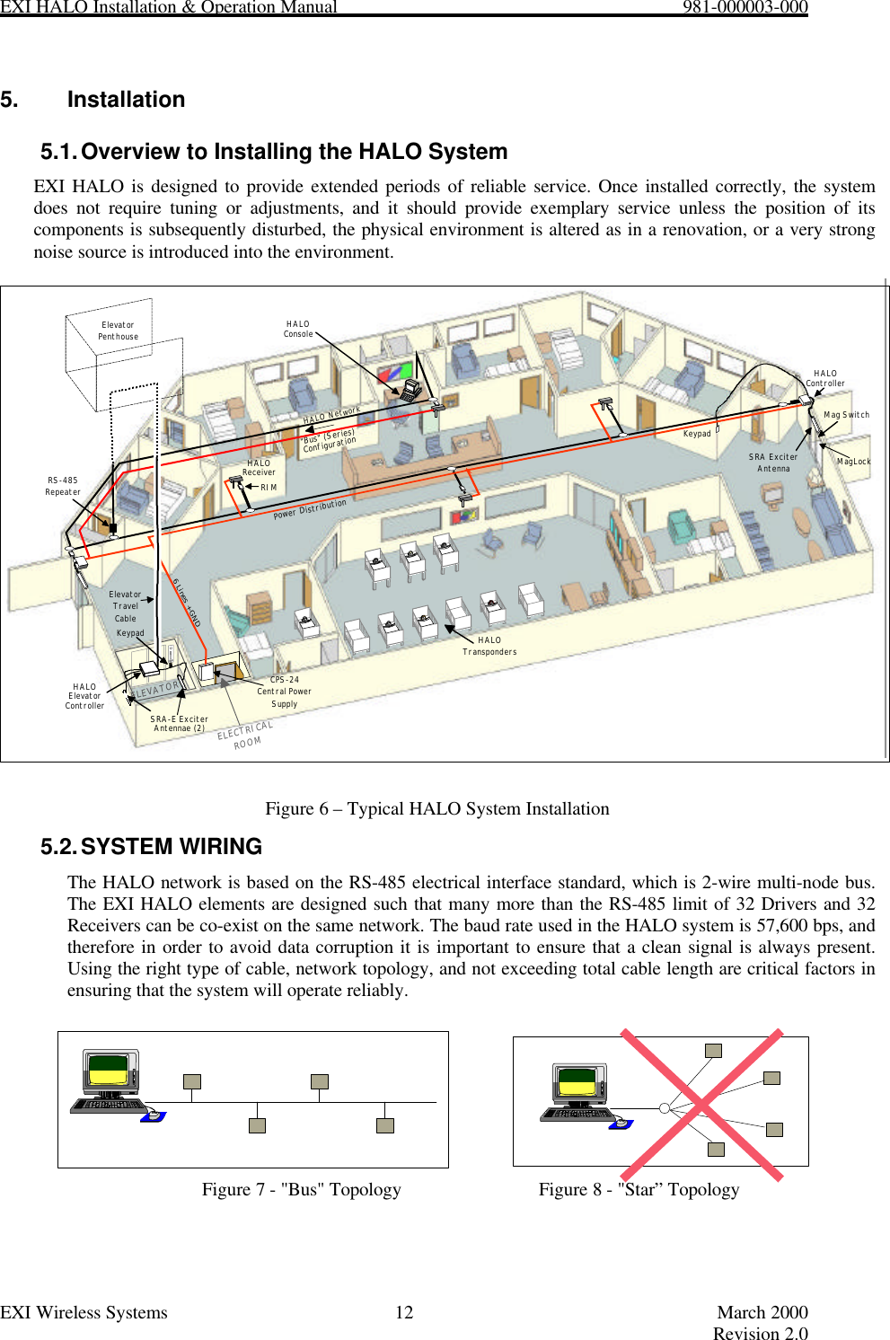
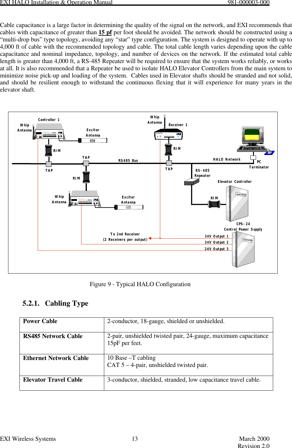
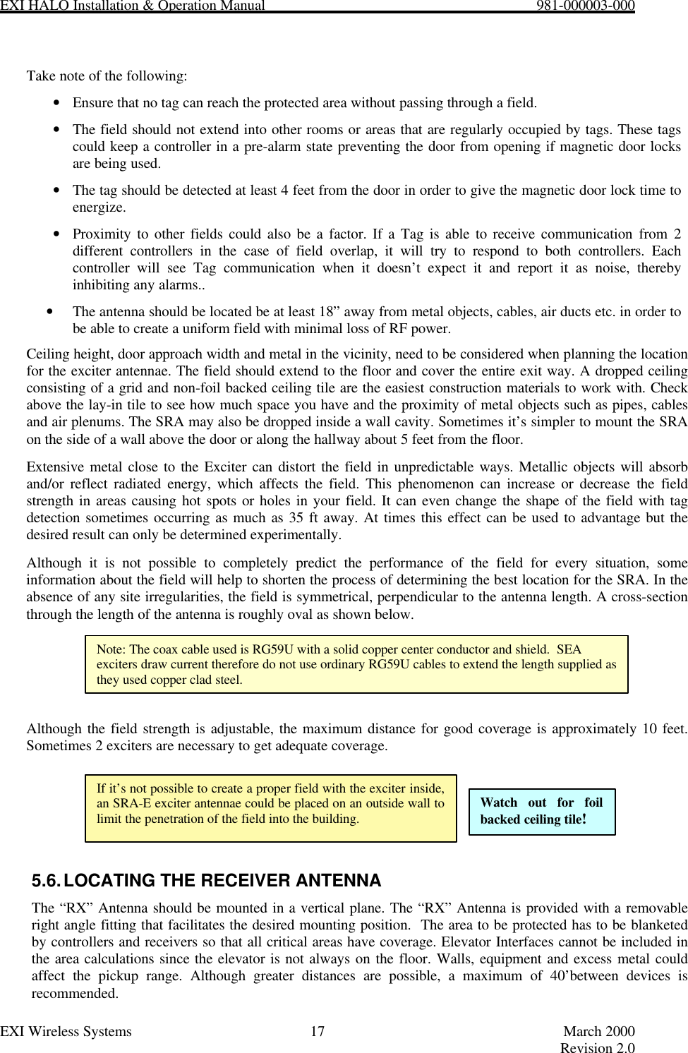

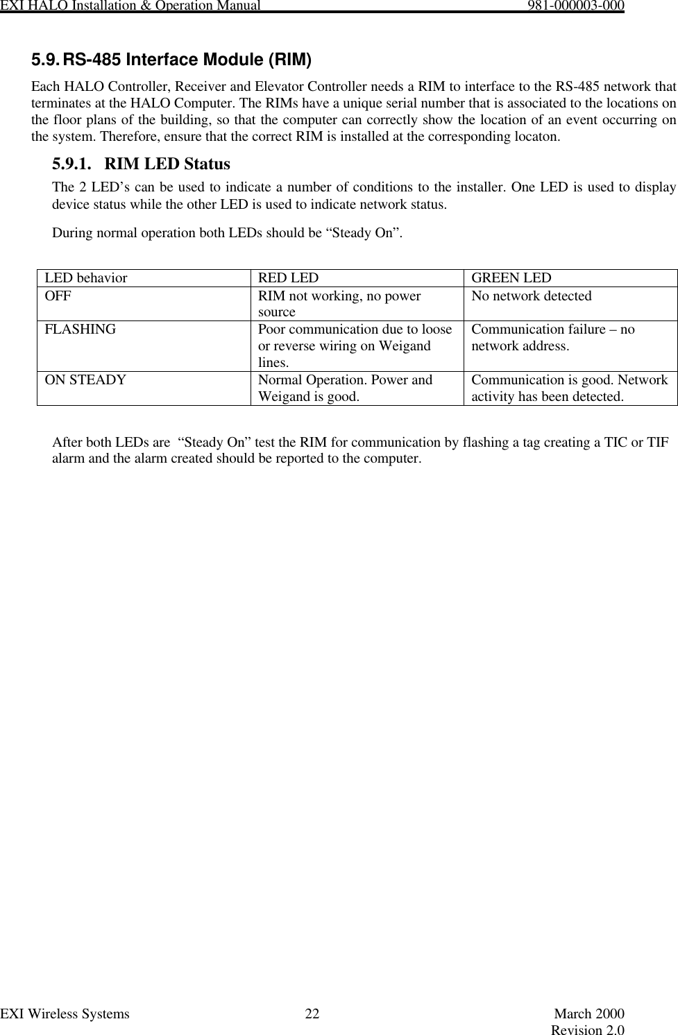
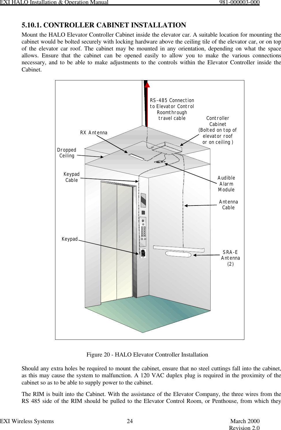
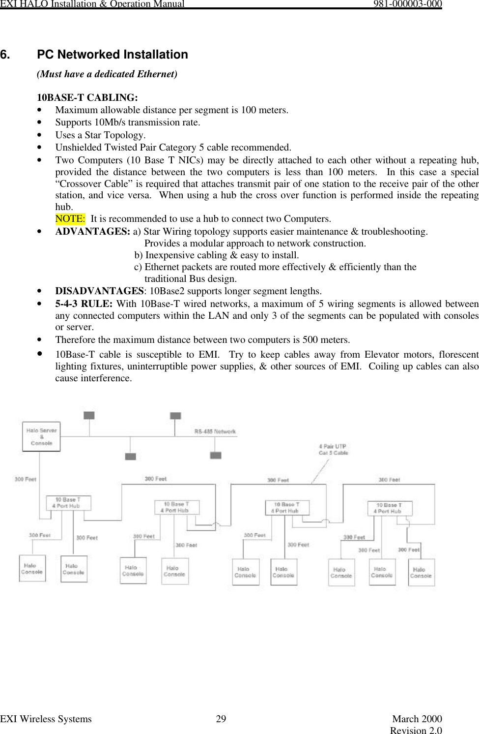
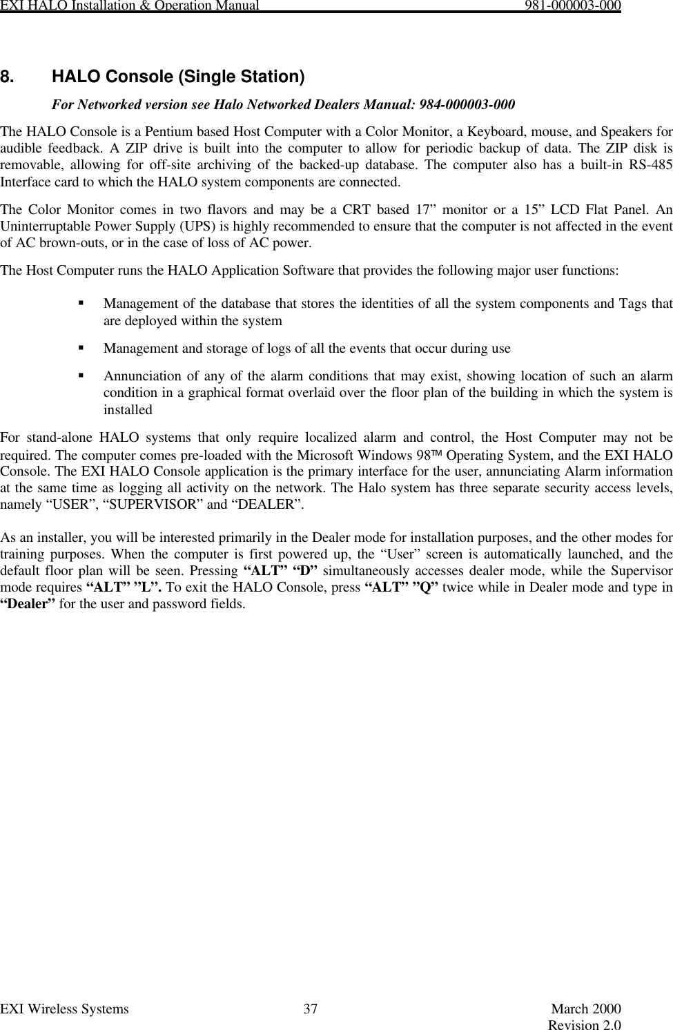
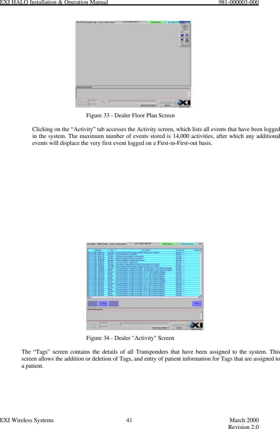
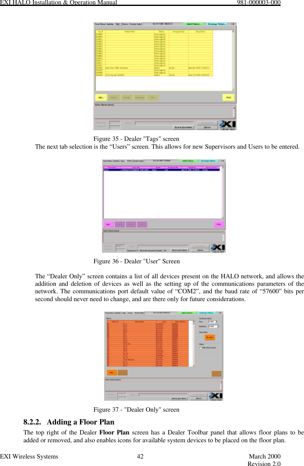
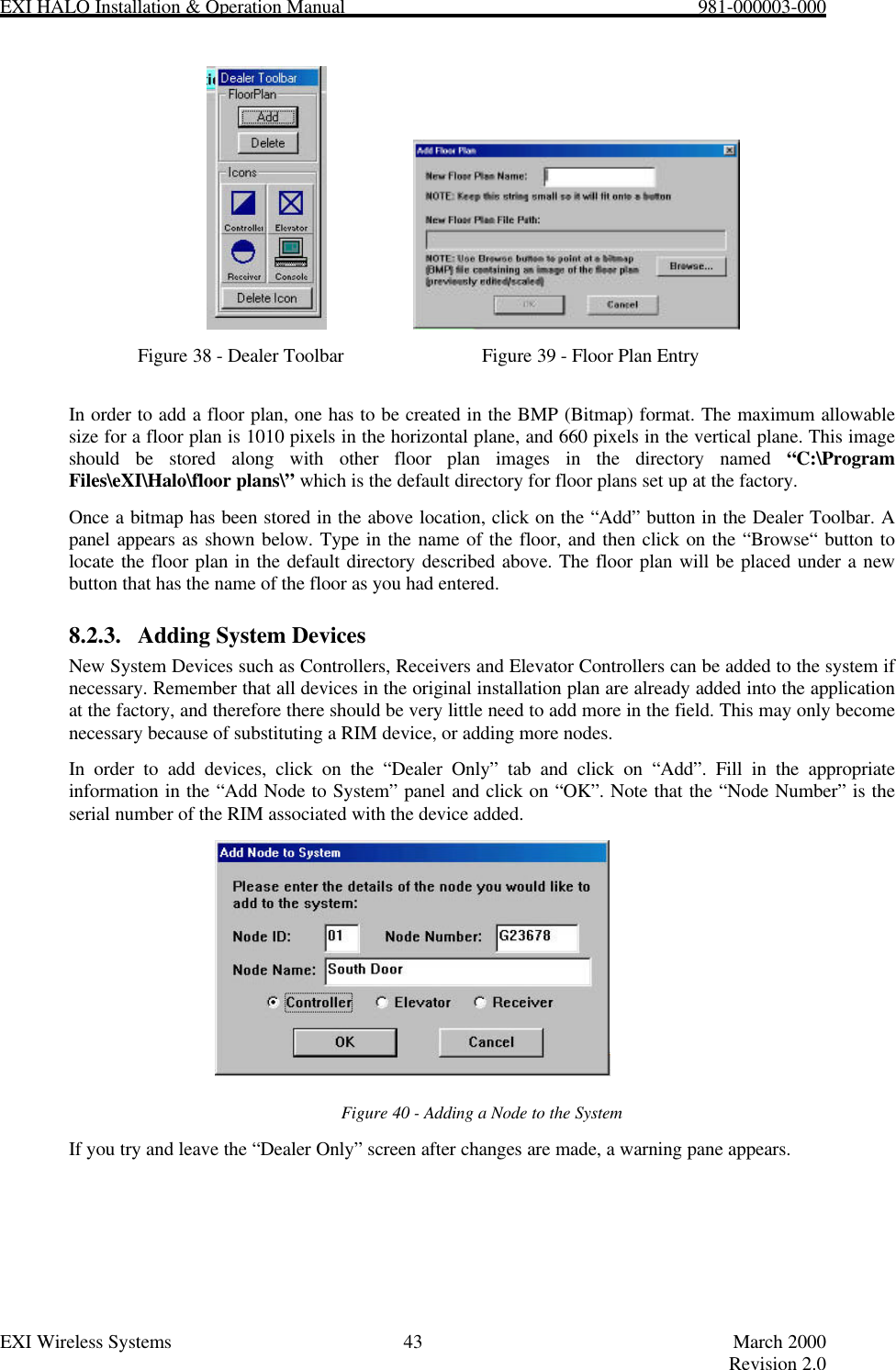
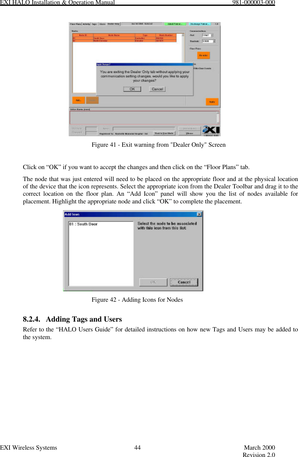
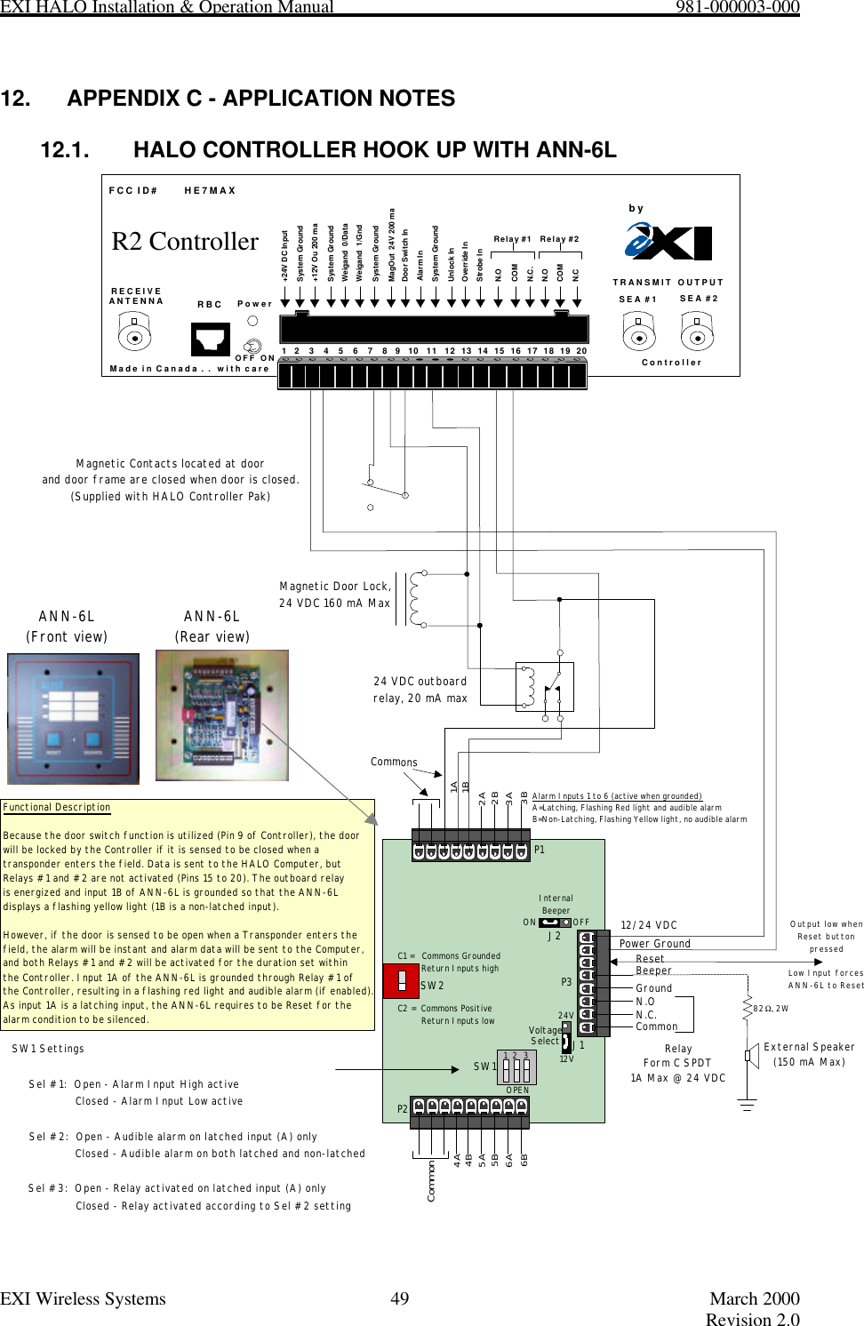
![EXI HALO Installation & Operation Manual 981-000003-000EXI Wireless Systems 23 March 2000Revision 2.05.10. INSTALLING ELEVATOR CONTROLLERSOnly one elevator system should be installed per elevator car. When installing an elevator system it is best tocoordinate with the local Elevator Company to ensure that the elevator controls are not affected by the HALOinstallation.Figure 19 - Elevator Cabinet Detailed Wiring DiagramRECEIVEANTENNA RBCFCC ID# HE7MAXTRANSMIT OUTPUTSEA #1 SEA #2Made in Canada . . with care ControllerbyPower1 2 3 4 5 6 7 8 9 10 11 12 13 14 15 16 17 18 19 20+24V DC InputSystem Ground+12V Ou 200 maSystem GroundWeigand 0/DataWeigand 1/GndSystem GroundMagOut 24V 200 maDoor Switch InSystem GroundUnlock InOverride InStrobe InN.OCOMN.C.N.OCOMN.CRelay #1 Relay #2Alarm InOFF ONR2 ControllerTC16/21 Cabinet24 V (-)24 V (+)PS-24VSRA-E #1 SRA-E #2RX Antenna1Common #1REDBROWNBLACKBLUEWHITEEIM126 A-7AUDIBLEALARMFactory SuppliedAudible AlarmCable(15')TestOperateElevator DoorDisableFactory SuppliedEIM CableDoor Switch(Closed - Door Closed)WHITEBLUEGREENBROWNBLACKRED15'Factory SuppliedCoaxial Cables(25')Max 10A110 VAC or 24VDCHALO "Controller"RBC/KEYPAD DOOR SWDRY CONTACTNC2NC1NO1NO2COM2COM1Not UsedCOM1 COM2DO NOT USENO1 NO2NC2NC1P2P1P4 P3P5Not UsedGREENNC11 2 34 5 67 8 9*0#KeypadEIMSIREN [-] PREALARM [-] TEST SWITCHPOS 12VKEY SWITCH GREEN LED [-] RIM To RS-485 Network throughElevator TravelCableRS-485WeigandBROWNGREENBLACKBLUEWHITEREDYELLOWGRAY](https://usermanual.wiki/Xmark/R3C/User-Guide-141015-Page-23.png)