Installation and Operations Manual

Revision 2.0
Installation and Operations Manual
March 2000
© Copyright 1999, EXI Wireless Systems Inc. All rights reserved.

EXI HALO Installation & Operation Manual 981-000003-000
EXI Wireless Systems 2March 2000
Revision 2.0
Table of Contents
1. LIMITED WARRANTY.............................................................................................................................. 4
2. RECORD OF CHANGES ............................................................................................................................ 6
3. FCC REGULATIONS.................................................................................................................................. 7
4. INTRODUCTION ........................................................................................................................................ 8
4.1. ABOUT HALO INFANT PROTECTION SYSTEM ............................................................................................. 8
4.2. SYSTEM COMPONENTS............................................................................................................................. 9
4.2.1. Door Control Package (Networked) – SR2C01N.............................................................................. 9
4.2.2. Elevator Package (Networked) – SR2L01N...................................................................................... 9
4.2.3. HALO Receiver Package (Networked) - SR2R01N ......................................................................... 10
4.2.4. Power Supply................................................................................................................................ 10
4.2.5. HALO Console.............................................................................................................................. 11
5. INSTALLATION ....................................................................................................................................... 12
5.1. OVERVIEW TO INSTALLING THE HALO SYSTEM ..................................................................................... 12
5.2. SYSTEM WIRING............................................................................................................................... 12
5.2.1. Cabling Type................................................................................................................................. 13
5.3. SYSTEM CONNECTION .................................................................................................................... 14
5.4. DOOR CONTROL ............................................................................................................................... 15
5.5. LOCATION FOR SRA EXCITER ANTENNAS................................................................................... 15
5.6. LOCATING THE RECEIVER ANTENNA .......................................................................................... 17
5.7. FINALIZE CONTROLLER INSTALLATION ..................................................................................... 18
5.8. INSTALLING RECEIVERS................................................................................................................. 20
5.8.1. Threshold Switch........................................................................................................................... 21
5.9. RS-485 INTERFACE MODULE (RIM)....................................................................................................... 22
5.9.1. RIM LED Status ............................................................................................................................ 22
5.10. INSTALLING ELEVATOR CONTROLLERS.................................................................................. 23
5.10.1. CONTROLLER CABINET INSTALLATION................................................................................... 24
5.10.2. LOCATION FOR SRA-E EXCITER ANTENNAS............................................................................ 25
5.10.3. Elevator Receive (RX) Antenna...................................................................................................... 26
5.10.4. Audible Alarm Module................................................................................................................... 26
5.10.5. Keypad.......................................................................................................................................... 26
5.10.6. “Door not Closed” Contact........................................................................................................... 27
5.10.7. Door Control and Fire Alarm Supervision ..................................................................................... 27
5.10.8. System Adjustment and Testing...................................................................................................... 28
5.11. SYSTEM GROUNDING CONSIDERATIONS................................................................................. 28
6. PC NETWORKED INSTALLATION....................................................................................................... 29
7. THEORY OF OPERATION...................................................................................................................... 31
7.1. TAG COMMUNICATIONS......................................................................................................................... 31
7.2. HALO SYSTEM COMMUNICATIONS........................................................................................................ 31
7.3. HALO CONTROLLER ........................................................................................................................ 32
7.4. KEYPAD.............................................................................................................................................. 33
7.5. HALO RECEIVER............................................................................................................................... 35
7.6. ELEVATOR CONTROLLER............................................................................................................... 35
7.6.1. Pre-Alarm..................................................................................................................................... 35
7.6.2. Full-Alarm .................................................................................................................................... 36
7.6.3. Elevator Bypass............................................................................................................................. 36

EXI HALO Installation & Operation Manual 981-000003-000
EXI Wireless Systems 3March 2000
Revision 2.0
8. HALO CONSOLE (SINGLE STATION).................................................................................................. 37
8.1. COMPUTER DISPLAY CONVENTIONS ....................................................................................................... 39
8.2. CONNECTING TO THE HOST COMPUTER .................................................................................................. 40
8.2.1. Navigating the Dealer Screens....................................................................................................... 40
8.2.2. Adding a Floor Plan...................................................................................................................... 42
8.2.3. Adding System Devices.................................................................................................................. 43
8.2.4. Adding Tags and Users.................................................................................................................. 44
9. DKX KEYPAD PROGRAMMING ........................................................................................................... 45
10. APPENDIX A - WEIGAND OUTPUT SPECIFICATION.................................................................... 46
11. APPENDIX B - ACCESSORIES............................................................................................................ 47
11.1. SELECT SOUND MODULE (SSM)................................................................................................. 47
11.2. ANN-6L SIX ZONE ANNUNCIATOR............................................................................................. 48
12. APPENDIX C - APPLICATION NOTES.............................................................................................. 49
12.1. HALO CONTROLLER HOOK UP WITH ANN-6L.......................................................................... 49
12.2. ANN-6L SWITCH CONFIGURATIONS................................................................................................... 50

EXI HALO Installation & Operation Manual 981-000003-000
EXI Wireless Systems 4March 2000
Revision 2.0
1. Limited Warranty
1. Warranty: Subject to the limiting conditions set forth below, EXI Wireless Systems Inc. (“EXI”) hereby
warrants that: (a) each product, other than transponders (the “Transponders”), accompanying this warranty
(the “Product”), will be free of defects in materials and workmanship for a period (the “Product Warranty
Period”) of two years after the date of the original sale by EXI of the Product; and (b) each Transponder
accompanying this warranty will be free of defects and workmanship for a period (the “Transponder
Warranty Period”) of, in the case of a WTX-INF/WS Transponder, four years, and in the case of all other
Transponders, three years, after the date of the original sale by EXI of the Transponder.
2. Notification: If the original or any subsequent purchaser (collectively, the “Purchaser”) of the Product or
Transponder, as the case may be, discovers a defect in materials or workmanship of a Product within the
Product Warranty Period, or a Transponder within the applicable Transponder Warranty Period, the
Purchaser must, within 30 days after the date of such discovery, notify EXI of such defect, and at EXI’s
request, return the defective Product or Transponder, as case the may be, to EXI.
3. Repair or Replacement: Subject to §4, upon acceptance by EXI of responsibility for the defect, EXI will,
in its sole discretion, (a) in the case of a Product, either replace the Product, or provide the Purchaser with
replacement parts for, or repair, the same; and (b) in the case of a Transponder, replace the Transponder at
a discounted price equal to the product of: (i) the nearest whole number of months remaining in the
applicable Transponder Warranty Period; and (ii) the amount of the then monthly credit available from EXI
for the applicable Transponder. EXI’s warranty in respect of any replacement Product, part thereof, or
Transponder, as the case may be, will be for the unexpired portion of the original warranty period
applicable to the relevant Product or Transponder.
4. Exclusion: The warranty referred to in §1 is the sole warranty made by EXI with respect to its Products
and Transponders. EXI makes no other warranty or representation, express or implied, and hereby
disclaims any implied warranty of merchantability or fitness for a particular purpose, statutory or
otherwise, concerning its Products and Transponders. In addition, the warranty will not apply if EXI has
not received a fully completed warranty registration card in respect of the Product or Transponder, as the
case may be, within 30 days after the date of the original purchase from EXI of the same, or the Product or
Transponder, as the case may be, or any part thereof: (a) is damaged by misuse, accident, negligence,
lightning, power surge, brown-out, or leaking, damaged or inoperative batteries, or failure to maintain the
Product or Transponder as specified or required by EXI; (b) is damaged by modifications, alterations or
attachments thereto which are not authorized by EXI; (c) is installed, operated or repaired contrary to the
instructions of EXI; (d) is opened, modified or disassembled in any way without EXI’s consent; or (d) is
used in combination with items, articles or materials not authorized by EXI.
5. Limitation: EXI will only be liable to the Purchaser for direct damages suffered by the Purchaser up to a
maximum amount equal to the total amount of the purchase price actually paid by the Purchaser to EXI for
the Product or Transponder, as the case may be. Specifically, EXI will not be liable for: (a) any special,
indirect or consequential damage, including lost profits, lost revenues, failure to realize expected savings,
or other commercial or economic losses of any kind, even if EXI has been advised of the possibility of such
damage; (b) any loss or damage to any property or for any personal injury or economic loss or damage
caused by the connection of the Product or Transponder, as applicable, to other devices or systems; (c) any
damage or injury arising from or as a result of, misuse, abuse or incorrect installation, integration or
operation of the Product or Transponder, as applicable, by persons not authorized by EXI; or (d) any defect
in any batteries added to or used in conjunction with the Product or Transponder.

EXI HALO Installation & Operation Manual 981-000003-000
EXI Wireless Systems 5March 2000
Revision 2.0
6. Product Limitation: The Purchaser (a) acknowledges that (i) the Products and the Transponders are not,
nor can they be, guaranteed to prevent wandering patients, infant abductions, theft or any other event for
which they were purchased, (ii) the Products and Transponders are only intended to provide additional
safeguards to assist in the prevention of events such as those described in §(i), and (b) understands fully the
foregoing limitations concerning the Products and Transponders, including EXI’s limitation on liability
described in §5, and agrees to warn, and obtain acknowledgements from, all users thereof of the same.
7. No Additional Warranties: The terms and conditions herein contain all the warranties and
representations concerning EXI’s Products and Transponders and supersede all previous negotiations,
understandings, communications, representations, warranties and agreements, whether verbal or written,
concerning the Products and Transponders.
8. Deemed Acceptance: The installation or use of the Product or Transponder by or at the direction of the
Purchaser will be deemed as an acceptance by the Purchaser of the terms hereof.
9. Governing Law: The warranty herein will be governed by the domestic laws of the Province of British
Columbia, Canada and the Purchaser hereby attorns to the exclusive jurisdiction of the laws of British
Columbia. The provisions of the United Nations Convention on Contracts for the International Sale of
Goods is hereby excluded.

EXI HALO Installation & Operation Manual 981-000003-000
EXI Wireless Systems 6March 2000
Revision 2.0
2. Record of Changes
October 1999 Combined HALO Installation & Operating Manual and Elevator Manual.
March 2000 Added Cabling types and Threshold / RX Sensitivity Switch Adjust.

EXI HALO Installation & Operation Manual 981-000003-000
EXI Wireless Systems 7March 2000
Revision 2.0
3. FCC Regulations
This device complies with Part 15 of the FCC Rules. Operation is subject to the following two conditions: (1) This
device may not cause harmful interference, and (2) This device must accept any interference received, including
interference that may cause undesired operation.
This equipment has been tested and found to comply with the limits for Class B Digital Device, pursuant to Part 15
of the FCC Rules. These limits are designed to provide reasonable protection against harmful interference in a
residential installation. This equipment generates and can radiate radio frequency energy and, if not installed and
used in accordance with the instructions, may cause harmful interference to radio communications. However, there
is no guarantee that interference will not occur in a particular installation. If this equipment does cause harmful
interference to radio or television reception, which can be determined by turning the equipment off and on, the user
is encouraged to try to correct the interference by one or more of the following measures.
• Reorient or relocate the receiving antenna
• Increase the separation between the equipment and receiver
• Connect the equipment into an outlet on a circuit different from that to which the receiver is connected
• Consult the dealer or an experienced radio/TV technician for help
Any changes or modifications not expressly approved by the party responsible for compliance could void the user’s
authority to operate the equipment.
EXI Wireless Systems Model No.: Patient Tag
CANADA: 287710217261A FCC ID: HE7 PTG
*
This device complies with Part 15 of the FCC Rules. Operation is
subject to the following two rules: (1) This device may not cause harmful
interference, and (2) This device must accept any interference received,
including interference that may cause undesired operation.
Made in Canada
EXI Wireless Systems Model No.: Halo Infant/ECO tag
CANADA: TBD FCC ID: HE7 ETG
*
This device complies with Part 15 of the FCC Rules. Operation is
subject to the following two rules: (1) This device may not cause harmful
interference, and (2) This device must accept any interference received,
including interference that may cause undesired operation.
Made in Canada
EXI Wireless Systems Model No.: Halo Asset tag
CANADA: TBD FCC ID: HE7 ATG
*
This device complies with Part 15 of the FCC Rules. Operation is
subject to the following two rules: (1) This device may not cause harmful
interference, and (2) This device must accept any interference received,
including interference that may cause undesired operation.
Made in Canada

EXI HALO Installation & Operation Manual 981-000003-000
EXI Wireless Systems 8March 2000
Revision 2.0
4. INTRODUCTION
This manual serves as a guide for Installers of the HALO system. The major components of the system are
described, as well as the system’s intended functionality, so as to gain familiarity with its operation prior to
installation. In order to successfully install and commission the system, it is absolutely critical to
understand the capabilities of the system and its components prior to installation.
4.1. About Halo Infant Protection System
Halo is a premium infant protection system. Halo works in conjunction with the EXI P-tag patient
transponder that is capable of sensing if it has been removed from the infant. Halo is an electronic system,
which, in conjunction with staff diligence, creates a secure perimeter to deter infant abductions.
The function of the HALO system is to monitor areas within a building for the presence of HALO Tags. A
Tag is sensed when it either enters an RF Field that is set up using the EXI HALO Controller (referred to as
a Tag in Field or TIF), or when the Tag initiates an alarm signal (referred to as Tag Initiated
Communications, or TIC).
HALO is designed to assist staff in providing a higher degree of safety for patients. It is not intended as
the sole means of protection in preventing a wanderer or infant from leaving the premises. Regular
checks to verify that your HALO system is operational is highly recommended.
SYSTEM MAINTENANCE SHOULD INCLUDE THE FOLLOWING STEPS:
All Tags should be checked for physical damage after each cleaning, disinfecting or sterilization
procedure.
Each Tag should be tested for correct operation before being attached to an infant. The HALO
software prompts for testing of Tags prior to their deployment. Please refer to the appropriate
section in this manual for the instructions.
The warranty on Tags is 3 years, and the batteries within the Tags are expected to last in excess of
the warranty period depending on the usage pattern. Do not leave Tags in the detection field for
long periods of time, and store them in the foil bags supplied. Failure to do so will result in false
alarms, and will reduce battery life.
Set up a regular system check schedule to verify that the Controllers, Receivers and Tags are
operational. Controllers should have the “Ready” light illuminated to show that they are powered.
Check the operation of the Controller daily by starting a bypass or triggering an alarm using a Tag
to ensure that it is fully operational and protecting the egress point where it is located.
Check each Receiver on a regular basis to ensure that it can receive signals from Tags in the “Off
Body” condition. Failure to regularly check for this operation may lead to failure to detect a Tag
that is removed from an infant, and therefore compromising protection for the infant.
Whenever you see an infant who is a patient, look for the Tag on this infant to verify that it is still
securely attached. This may require special knowledge as to the placement of the Tag.
Conduct frequent back-ups of Activity Logs for future reference.
EXI HALO Installation & Operation Manual 981-000003-000
EXI Wireless Systems 9March 2000
Revision 2.0
4.2. System Components
This section describes the various system components required to complete the installation of the HALO
system.
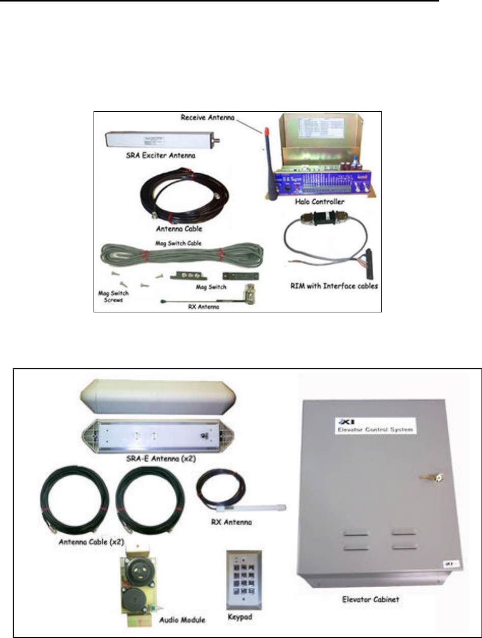
4.2.1. Door Control Package (Networked) – SR2C01N
Figure 1 - Halo Controller Package
4.2.2. Elevator Package (Networked) – SR2L01N
Figure 2 - HALO Elevator Controller Package
EXI HALO Installation & Operation Manual 981-000003-000
EXI Wireless Systems 10 March 2000
Revision 2.0
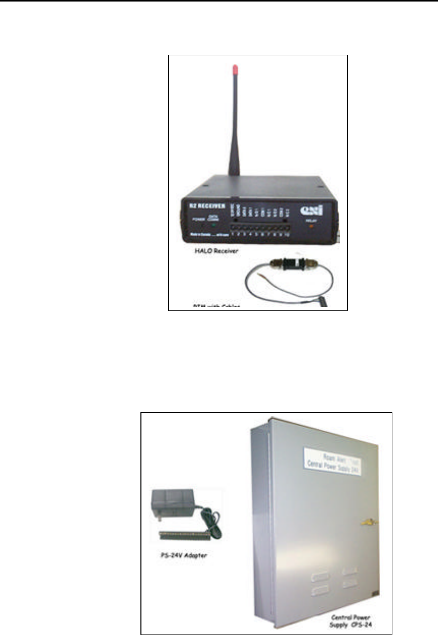
4.2.3. HALO Receiver Package (Networked) - SR2R01N
Figure 3 - HALO Receiver Package
4.2.4. Power Supply
Individual power supply adapters Model # AR2PS01-024 may be used for each of the Door Control
Packages and the Receivers. Alternatively, a Central Power Supply Model # AGECP01-624 has 6
independent inputs, each of which can power one Controller or two Receivers. The CPS may be purchased
with a battery back-up option, which is highly recommended.
Figure 4 – Power Supply choices

EXI HALO Installation & Operation Manual 981-000003-000
EXI Wireless Systems 11 March 2000
Revision 2.0
4.2.5. HALO Console
Figure 5 - HALO Computer Package
EXI HALO Installation & Operation Manual 981-000003-000
EXI Wireless Systems 12 March 2000
Revision 2.0
5. Installation
5.1. Overview to Installing the HALO System
EXI HALO is designed to provide extended periods of reliable service. Once installed correctly, the system
does not require tuning or adjustments, and it should provide exemplary service unless the position of its
components is subsequently disturbed, the physical environment is altered as in a renovation, or a very strong
noise source is introduced into the environment.
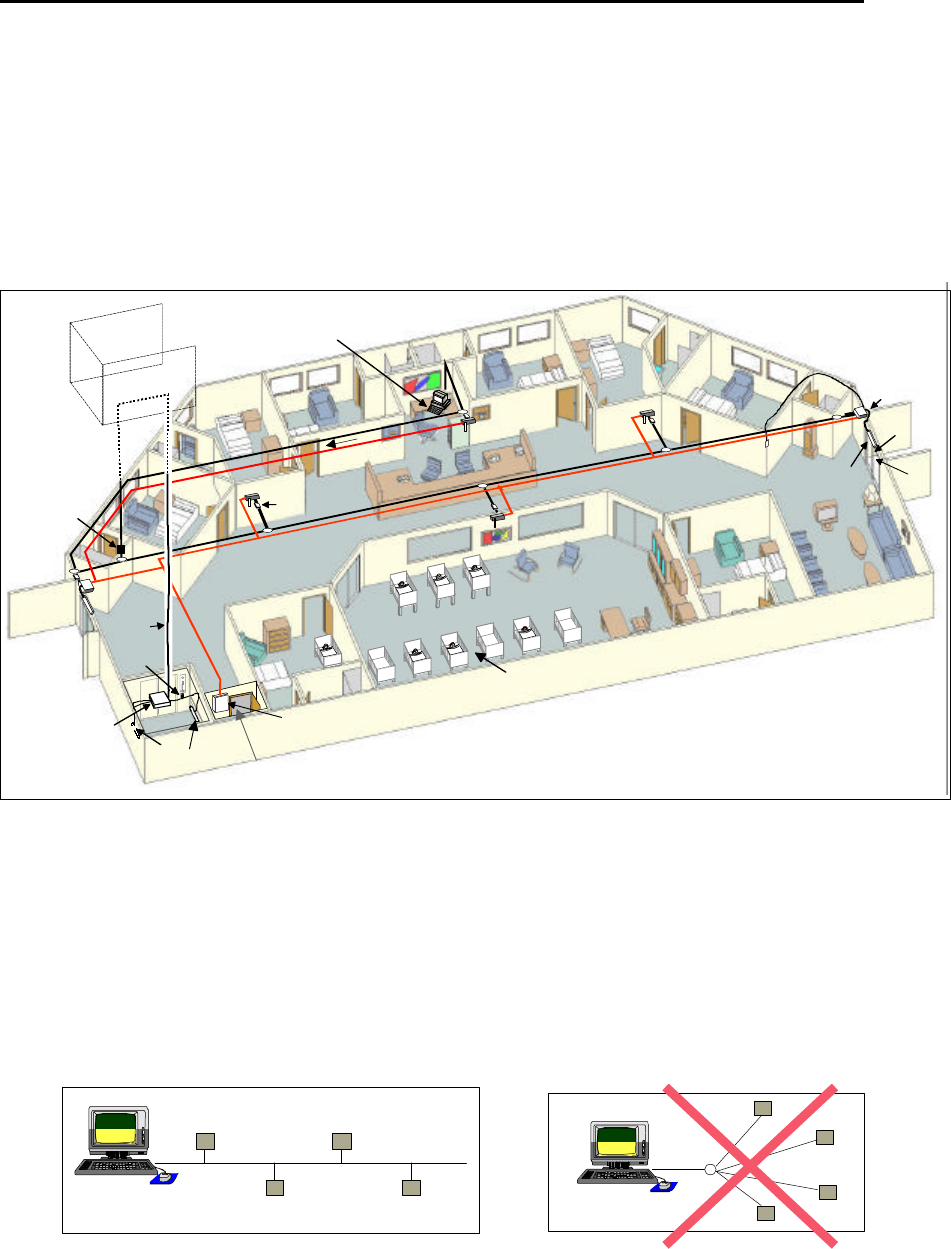
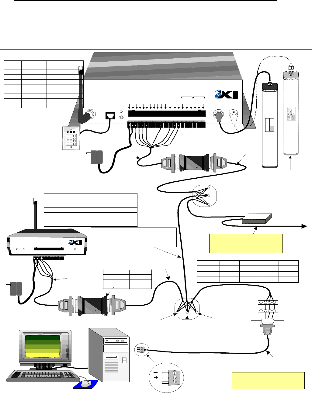
Figure 6 – Typical HALO System Installation
5.2. SYSTEM WIRING
The HALO network is based on the RS-485 electrical interface standard, which is 2-wire multi-node bus.
The EXI HALO elements are designed such that many more than the RS-485 limit of 32 Drivers and 32
Receivers can be co-exist on the same network. The baud rate used in the HALO system is 57,600 bps, and
therefore in order to avoid data corruption it is important to ensure that a clean signal is always present.
Using the right type of cable, network topology, and not exceeding total cable length are critical factors in
ensuring that the system will operate reliably.
Figure 7 - "Bus" Topology Figure 8 - "Star” Topology
RIM
HALO Network
SRA Exciter
Antenna
Keypad
HALO
Controller
SRA-E Exciter
Antennae (2)
HALO
Receiver
Keypad
Mag Switch
MagLock
Elevator
Penthouse
CPS-24
Central Power
Supply
Power Distribution
HALO
Transponders
HALO
Elevator
Controller
ELEVATOR
ELECTRICAL
ROOM
Elevator
Travel
Cable
HALO
Console
RS-485
Repeater
6 Lines + GND
"Bus" (Series)
Configuration
EXI HALO Installation & Operation Manual 981-000003-000
EXI Wireless Systems 13 March 2000
Revision 2.0
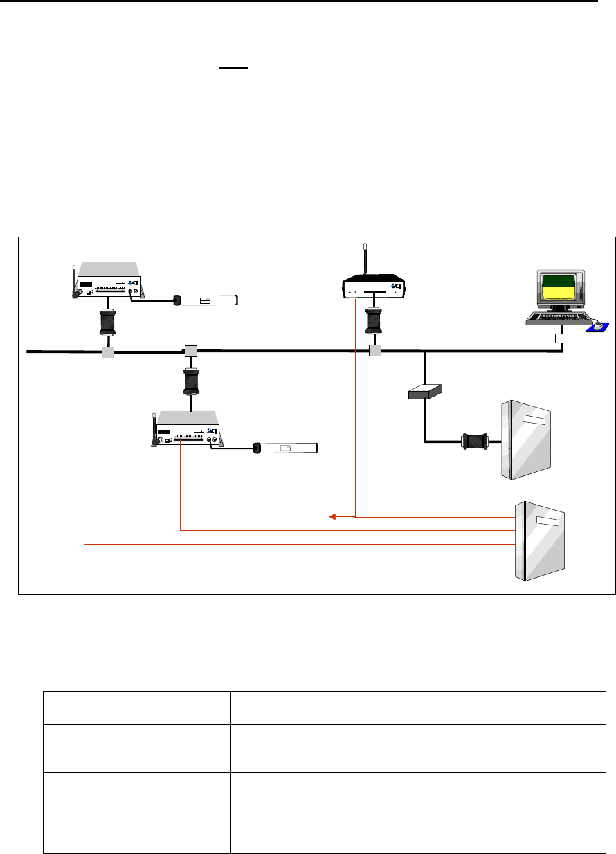
Cable capacitance is a large factor in determining the quality of the signal on the network, and EXI recommends that
cables with capacitance of greater than 15 pf per foot should be avoided. The network should be constructed using a
“multi-drop bus” type topology, avoiding any “star” type configuration. The system is designed to operate with up to
4,000 ft of cable with the recommended topology and cable. The total cable length varies depending upon the cable
capacitance and nominal impedance, topology, and number of devices on the network. If the estimated total cable
length is greater than 4,000 ft, a RS-485 Repeater will be required to ensure that the system works reliably, or works
at all. It is also recommended that a Repeater be used to isolate HALO Elevator Controllers from the main system to
minimize noise pick-up and loading of the system. Cables used in Elevator shafts should be stranded and not solid,
and should be resilient enough to withstand the continuous flexing that it will experience for many years in the
elevator shaft.
Figure 9 - Typical HALO Configuration
5.2.1. Cabling Type
Power Cable 2-conductor, 18-gauge, shielded or unshielded.
RS485 Network Cable 2-pair, unshielded twisted pair, 24-gauge, maximum capacitance
15pF per feet.
Ethernet Network Cable 10 Base –T cabling
CAT 5 – 4-pair, unshielded twisted pair.
Elevator Travel Cable 3-conductor, shielded, stranded, low capacitance travel cable.
R2 RECEIVER
DATA
COMM.
Made in Canada . . with care
12/24 VDC
GROUND
DATA 0
DATA 1
N/O 1
COM 1
N/C 1
N/O 2
COM 2
N/C 2
1 2 3 4 5 6 7 8 9 10
POWER RELAY
Controller 1
Whip
Antenna Exciter
Antenna
HALO Network
RECEIVE
ANTENNA RBC
FCC ID# HE7MAX
TRANSMIT OUTPUT
SEA #1 SEA #2
Made in Canada . . with care Controller
by
Power
1 2 3 4 5 6 7 8 9 10 11 12 13 14 15 16 17 18 19 20
+24V DC Input
System Ground
+12V Ou 200 ma
System Ground
Weigand 0/Data
Weigand 1/Gnd
System Ground
MagOut 24V 200 ma
Door Switch In
System Ground
Unlock In
Override In
Strobe In
N.O
COM
N.C.
N.O
COM
N.C
Relay #1 Relay #2
Alarm In
OFF ON
EXI ELECTRONIC SYSTEMS
Winnipeg, Manitoba (204) 788-1696
Made in Canada
PRODUCT
MODEL NO.
SERIAL NO>
ROAM II/TAGRRR
SEA-M
1118
24V Output 1
Whip
Antenna Exciter
Antenna
RECEIVE
ANTENNA RBC
FCC ID# HE7MAX
TRANSMIT OUTPUT
SEA #1 SEA #2
Made in Canada . . with care Controller
by
Power
1 2 3 4 5 6 7 8 9 10 11 12 13 14 15 16 17 18 19 20
+24V DC Input
System Ground
+12V Ou 200 ma
System Ground
Weigand 0/Data
Weigand 1/Gnd
System Ground
MagOut 24V 200 ma
Door Switch In
System Ground
Unlock In
Override In
Strobe In
N.O
COM
N.C.
N.O
COM
N.C
Relay #1 Relay #2
Alarm In
OFF ON
RIM
RIM
Receiver 1
Whip
Antenna
RIM
RS485 Bus
TAP
TAP
TAP
PC
Terminator
RS-485
Repeater
Elevator Controller
RIM
EXI ELECTRONIC SYSTEMS
Winnipeg, Manitoba (204) 788-1696
Made in Canada
PRODUCT
MODEL NO.
SERIAL NO>
ROAM II/TAGRRR
SEA-M
1118
CPS-24
Central Power Supply
24V Output 2
24V Output 3
To 2nd Receiver
(2 Receivers per output)
Central Power Supply
Elevator Control System
EXI HALO Installation & Operation Manual 981-000003-000
EXI Wireless Systems 14 March 2000
Revision 2.0
5.3. SYSTEM CONNECTION
The figure below shows the details of connecting the various system components together for the HALO
system.
Figure 10 - Detailed System Diagram
RECEIVE
ANTENNA RBC
FCC ID# HE7MAX
TRANSMIT OUTPUT
SEA #1 SEA #2
Made in Canada . . with care Controller
by
Power
1 2 3 4 5 6 7 8 9 10 11 12 13 14 15 16 17 18 19 20
+24V DC Input
System Ground
+12V Out 200 ma
System Ground
Weigand 0/Data
Weigand 1/Gnd
System Ground
MagOut 24V 200 ma
Door Switch In
System Ground
Unlock In
Override In
Strobe In
N.O
COM
N.C.
N.O
COM
N.C
Relay #1 Relay #2
Alarm In
OFF ON
R2 Controller
RS+
RS-
GND
RS+
RS-
GND
R2 RECEIVER
DATA
COMM.
Made in Canada . . with care
12/24 VDC
GROUND
DATA 0
DATA 1
N/O 1
COM 1
N/C 1
N/O 2
COM 2
N/C 2
POWER RELAY
1 2 3 4 5 6 7 8 9 10
DKX
Keypad
Optional
PS-24
Power
Supply
EXI ELECTRONIC SYSTEMS
Winnipeg, Manitoba (204) 788-1696
Made in Canada
PRODUCT
MODEL NO.
SERIAL NO>
ROAM II/TAGRRR
SEA-M
1118
Brn
RIM
Grn
Blk
Blu
Whi
Red
Yel
1 2 3
4 5 6
7 8 9
*0#
Grn
Blk
Blu
RIM
R2 TAP
PC Terminator
Box
PC to
Network Cable
RS-485
Weigand
Brn
Pin# Wire
Color Function
3 Brown +12/24 V
4 Green System GND
5 Black Weigand 0/Data
6 Blue Weigand 1/Data
10 White Alarm In
12 Red Unlock In
13 Yellow Override In
14 Gray Strobe In
Factory
Wired
Factory
Wired
RS-485 Shielded Cable, 24 AWG
Maximum Capacitance 15 pf per foot
Example: Electro Cables FT-4 Part #5302452
Daisy Chain (Series) Configuration as much as
possible.
RS-485 Connector (To Halo
NetworkController Output)
DB9
R2
Receiver
Pin
Function Wire
Color DB 25
1 +12/24V Brown 14
2 System GND Green 7
3 Data 0 Black 20
4 Data 1 Blue 22
TAP
Optional
PS-24
Power
Supply
Pin # Function
9 or 12 RS +
7 GND
22 or 25 RS -
RIM Pin-Out
Com
NOTE: Check all network
wiring before connecting
to the PC.
Enlarged
View
RS +
Gnd
RS -
Caution: Ensure appropriate
stranded cables are used for
Elevator Shafts due to the
continuous flexing they will
have to endure!
Factory
Supplied
Factory
Supplied
RS-485
Weigand
Factory
Supplied
Optional RS-485 Repeater
(Required for total cable length
of greater than 4,000 ft, and
highly recommended for isolation
of Halo Elevator Controller)
RS-485
Repeater
Halo Receiver Connector Pin-Out
Halo Controller Connector Pin-Out
Optional, to
Enhance
Coverage
Elevator System or
other devices
Function Type 1 Type 2 Type 3 Type 4
RS + Yellow Brown Black Red
GND Green Blue White Green
RS - White Red Red Black
RS-485 3-Conductor Cable Code
(All have same function, but 4 versions of wire color)
O
r
a
n
g
e
o
r
G
r
a
y
EXI HALO Installation & Operation Manual 981-000003-000
EXI Wireless Systems 15 March 2000
Revision 2.0
5.4. DOOR CONTROL
The controller chassis may be horizontally or vertically mounted, on a wall, ceiling or shelf and should be
mounted so that the front face panel is easily accessible. Since it is preferable to leave the RX antenna attached
directly to the controller, the exact location of the controller will affect the reception of the tags and should
only be finalized after setting up the field. The RX antenna should be positioned on a vertical plane for
maximum performance.
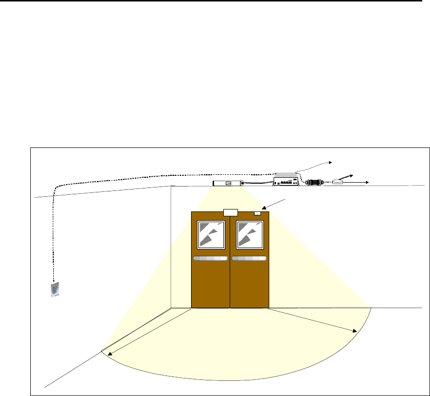
Figure 11 – Door Coverage
• Mount the Keypad about 10’ away from door so that it can be used before entering the detection
field.
• Maglock release should be hooked up to an unused auxiliary normally open contact from Fire
Alarm Panel.
5.5. LOCATION FOR SRA EXCITER ANTENNAS
One of the most important aspect of the entire installation is the correct positioning of the SRA Exciter
Antenna. The Antenna may be installed:
Ø above the doorway, laid flat on the dropped ceiling tile.
Ø dropped inside a wall cavity 4’ above the floor.
Ø on the side wall along the hallway 4’ above the floor.
Each field needs to be fully tested to ensure adequate coverage of the protected area.
HALO
Controller
Door Sense
Magnetic Switch
Keypad
Exciter Antenna
Mag-Lock
EXI ELECTRONIC SYSTEMS
Winnipeg, Manitoba (204) 788-1696
Made in Canada
PRODUCT
MODEL NO.
SERIAL NO>
ROAM II/TAGRRR
SEA-M
1118
Roam II & Tagrrr
RECEIVE
ANTENNA RBC
FCC ID# HE7MAX
TRANSMIT OUTPUT
SEA #1 SEA #2
Made in Canada . . with care Controller
by
Power
1 2 3 4 5 6 7 8 9 10 11 12 13 14 15 16 17 18 19 20
+24V DC Input
System Ground
+12V Ou 200 ma
System Ground
Weigand 0/Data
Weigand 1/Gnd
System Ground
MagOut 24V 200 ma
Door Switch In
System Ground
Unlock In
Override In
Strobe In
N.O
COM
N.C.
N.O
COM
N.C
Relay #1Relay #2
Alarm In
OFF ON
D
e
t
e
c
t
i
o
n
A
r
e
a
~
1
0
'
RIM
TAP
To other
Devices
To Computer
Power
EXI HALO Installation & Operation Manual 981-000003-000
EXI Wireless Systems 16 March 2000
Revision 2.0
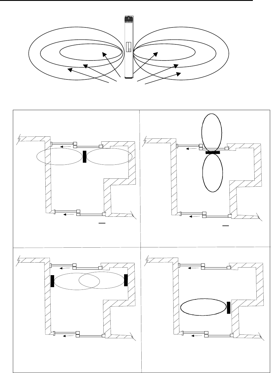
Figure 12 - SRA Antenna Exciter Field
Figure 13 - SRA Antenna Installation and Coverage
POOR COVERAGE
Surface mounted SEA on low plaster board,
wood plankor dropped ceiling, provides
approximately 12' horizontal coverage and
approximately 8 - 10' down from ceiling.
Surface mounted SEA on low plaster board,
wood plankor dropped ceiling, directly above
sliding door, provides approximately 6 - 8'
horizontal and 8 - 10' vertical coverage down
from ceiling.
Economical
2 SEA's horizontally surface wall mounted
4'6" up from floor, directly opposite each
other. Provides 10' horizontal coverage
from floor to ceiling.
one horizontal, surface mounted SEA 4'6"
up from floor, provides 6 - 7' horizontal
coverage and 10' vertical coverage from
floor to ceiling. However, close proximity to
inner door may not be suitable due to nearby
wanderers in corridor.
A) GOOD COVERAGE B) POOR COVERAGE
C) GOOD COVERAGE D) GOOD COVERAGE
Detection Areas
EXI ELECTRONIC SYSTEMS
Winnipeg, Manitoba (204) 788-1696
Made in Canada
PRODUCT
MODEL NO.
SERIAL NO>
ROAM II/TAGRRR
SEA-M
1118

EXI HALO Installation & Operation Manual 981-000003-000
EXI Wireless Systems 17 March 2000
Revision 2.0
Take note of the following:
• Ensure that no tag can reach the protected area without passing through a field.
• The field should not extend into other rooms or areas that are regularly occupied by tags. These tags
could keep a controller in a pre-alarm state preventing the door from opening if magnetic door locks
are being used.
• The tag should be detected at least 4 feet from the door in order to give the magnetic door lock time to
energize.
• Proximity to other fields could also be a factor. If a Tag is able to receive communication from 2
different controllers in the case of field overlap, it will try to respond to both controllers. Each
controller will see Tag communication when it doesn’t expect it and report it as noise, thereby
inhibiting any alarms..
• The antenna should be located be at least 18” away from metal objects, cables, air ducts etc. in order to
be able to create a uniform field with minimal loss of RF power.
Ceiling height, door approach width and metal in the vicinity, need to be considered when planning the location
for the exciter antennae. The field should extend to the floor and cover the entire exit way. A dropped ceiling
consisting of a grid and non-foil backed ceiling tile are the easiest construction materials to work with. Check
above the lay-in tile to see how much space you have and the proximity of metal objects such as pipes, cables
and air plenums. The SRA may also be dropped inside a wall cavity. Sometimes it’s simpler to mount the SRA
on the side of a wall above the door or along the hallway about 5 feet from the floor.
Extensive metal close to the Exciter can distort the field in unpredictable ways. Metallic objects will absorb
and/or reflect radiated energy, which affects the field. This phenomenon can increase or decrease the field
strength in areas causing hot spots or holes in your field. It can even change the shape of the field with tag
detection sometimes occurring as much as 35 ft away. At times this effect can be used to advantage but the
desired result can only be determined experimentally.
Although it is not possible to completely predict the performance of the field for every situation, some
information about the field will help to shorten the process of determining the best location for the SRA. In the
absence of any site irregularities, the field is symmetrical, perpendicular to the antenna length. A cross-section
through the length of the antenna is roughly oval as shown below.
Although the field strength is adjustable, the maximum distance for good coverage is approximately 10 feet.
Sometimes 2 exciters are necessary to get adequate coverage.
5.6. LOCATING THE RECEIVER ANTENNA
The “RX” Antenna should be mounted in a vertical plane. The “RX” Antenna is provided with a removable
right angle fitting that facilitates the desired mounting position. The area to be protected has to be blanketed
by controllers and receivers so that all critical areas have coverage. Elevator Interfaces cannot be included in
the area calculations since the elevator is not always on the floor. Walls, equipment and excess metal could
affect the pickup range. Although greater distances are possible, a maximum of 40’between devices is
recommended.
If it’s not possible to create a proper field with the exciter inside,
an SRA-E exciter antennae could be placed on an outside wall to
limit the penetration of the field into the building. Watch out for foil
backed ceiling tile!
Note: The coax cable used is RG59U with a solid copper center conductor and shield. SEA
exciters draw current therefore do not use ordinary RG59U cables to extend the length supplied as
they used copper clad steel.
EXI HALO Installation & Operation Manual 981-000003-000
EXI Wireless Systems 18 March 2000
Revision 2.0
It is essential that the RX antennas have no metal barriers blocking the signals from the Tags although some
metal objects may enhance communication by reflecting the signal further than it would normally transmit.
Wire glass sometimes found around nurseries can cut down the range. The only way to be sure of adequate
coverage is by testing the results. After all devices are installed and operational, ensure that the entire area has
coverage. Experience will shorten this process as the installer learns what site conditions cause problems.
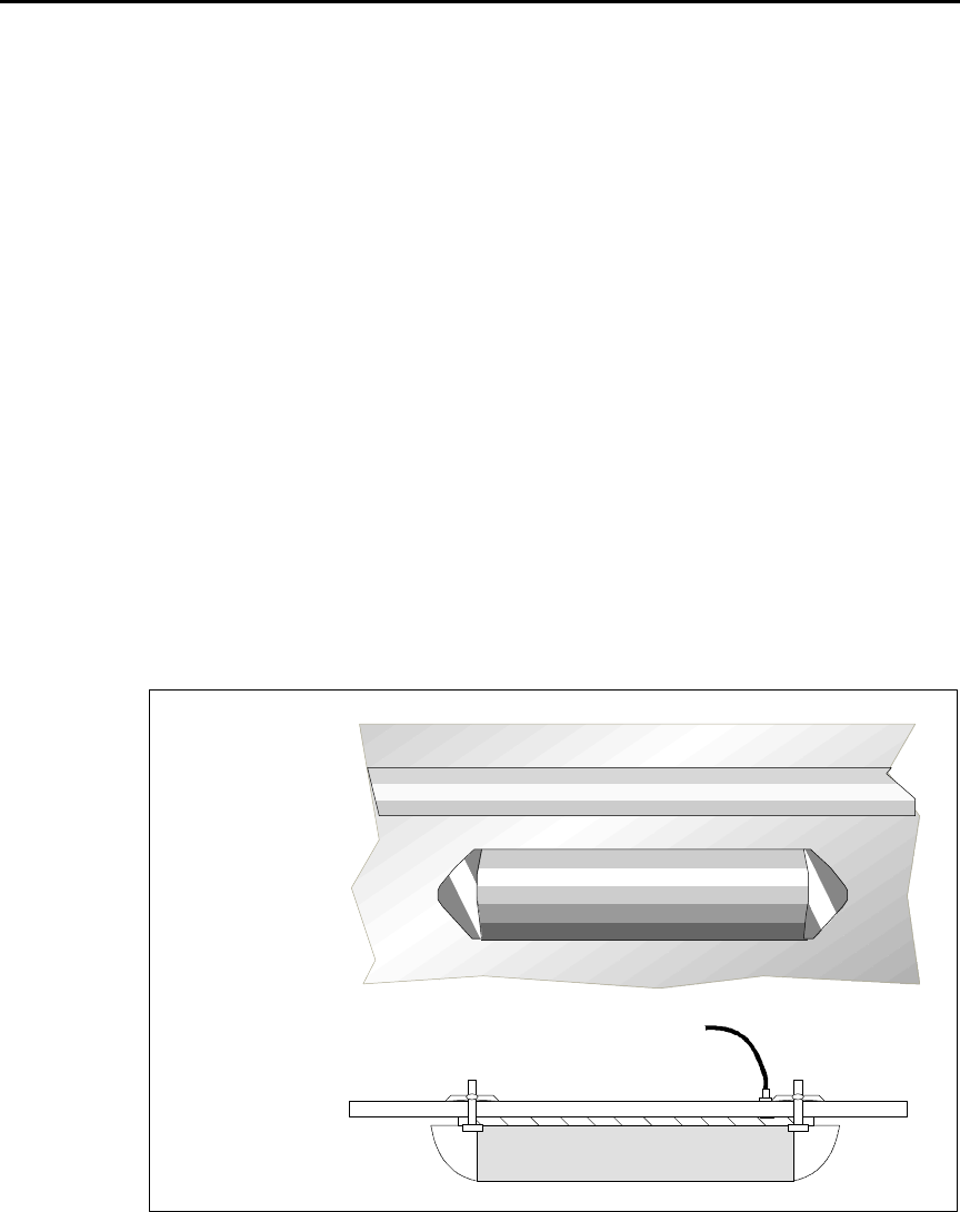
5.7. FINALIZE CONTROLLER INSTALLATION
Fasten SRA exciter antenna. If installing the SRA above a ceiling tile, use a marker pen to draw an outline of
the SRA in its desired position on the upper side of the tile. Once you are certain of the SRA location, use
some adhesive or caulk to cement the SRA to the tile, preventing it from falling on the floor should the tile be
lifted for any reason.
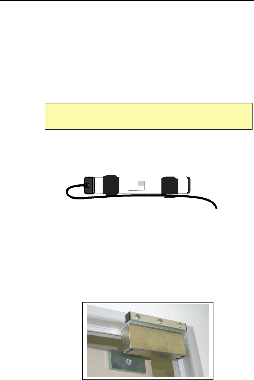
If the SRA is to be dropped inside a wall cavity, do not let it hang on the coax cable nor hang so low that it
touches the bottom steel plate. Loop the coax cable and wrap a tie-wrap, or band of electrical tape around it as
shown below. Ensure the SRA will hang at the correct height by marking the cable prior to dropping the SRA
inside the wall. Secure the cable when the SRA is hanging in the correct position.
Figure 14 - Securing the Exciter Antenna Cable
Mount the Controller permanently and position the RX antenna. Place the RIM close to the Controller and
connect the three wires on the RS-485 side of the RIM to the RS-485 network. This may be done by using
crimp type connectors, or by means of an EXI TAP box.
The Keypad is designed for flush wall mounting in a standard single-gang electrical box. Should surface
mounting be necessary, an optional SMB box may be used. Should a louder local alarm be desired, either use a
Wire-mold box extension and break out the knock out holes before mounting the panel, or install an external
siren or other audible device.
Install door switch. Hook up Maglock and any peripheral devices. Make sure the Maglock will release in case
of a Fire Alarm. Power up and test the field again.
Figure 15 - Maglock Installation
RIMs have unique serial numbers that are associated with the Controller or
Receiver location that they serve. Ensure that the correct RIM is used at the
location being entered on the floor plan in the computer!
EXI ELECTRONIC SYSTEMS
Winnipeg, Manitoba (204) 788-1696
Made in Canada
PRODUCT
MODEL NO.
SERIAL NO>
ROAM II/TAGRRR
SEA-M
1118
EXI HALO Installation & Operation Manual 981-000003-000
EXI Wireless Systems 19 March 2000
Revision 2.0
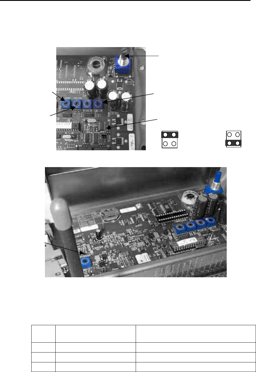
5.7.1.1. CONTROLLER CONFIGURATION SWITCHES
Figures 16 and 17 – Controller Switch Identification
5.7.1.2. MODE SWITCH SETTING
Mode
Switch
Controller Function Response
0Test Mode
3Patient Monitoring with Keypad Alarm ends on its own – fixed maximum bypass time
4Patient Monitoring with Keypad Continuous alarm - fixed maximum bypass time
1
2
“Mode” Switch
“Option” Switch
SRA Antenna Adjust
1
2
Relay 1 = TIF
Relay 2 = TIC Both Relays
active on TIF
J2: Relay function
Transponder Ranges
(Not used)
Threshold / RX
Sensitivity
Switch

EXI HALO Installation & Operation Manual 981-000003-000
EXI Wireless Systems 20 March 2000
Revision 2.0
5.7.1.3. OPTION SWITCH SETTING
Option
Switch Function Patient Monitoring Authorized Entry
0Don’t act on any Tags No Tags are stopped No Tags authorized
1Act on all Tags All Tags will be
stopped All Tags authorized
5.7.1.4. THRESHOLD / RX SENSITIVITY SWITCH
The Threshold switch may be adjusted to increase or reduce the sensitivity of the Receiver and therefore
the range of detection of the Tag.
It is also used to remove some of the background noise as well as reduce interference from tags if the
controller is having trouble detecting tags. The result in the adjustment raises the RF field strength
threshold received from the tags in order to trigger the CPM into alarm (ie. from 25uV to 50uV) and
reduces the detection field range.
‘0’ = MAX sensitivity & ‘F’ = MIN sensitivity. The default setting is “2”.
5.7.1.5. TEST CONTROLLER AND SET UP FIELDS
After reading LOCATION FOR SRA EXCITER ANTENNAS, choose a suitable location for the SRA.
Setting up a field is a matter of experience gained by trial and error. The primary considerations here are
the field shape and strength. The field has to fill the area in front of the door all the way to the floor so that
no tag can reach the door without being detected.
To set up a field, start by placing the tag at the range you want for the field at the height a tag is usually
going to be found. The tag needs to be detected far enough from the door to allow the magnetic door lock
time to energize. The tag should be placed on a non-metallic surface for testing. You might want to do a
preliminary field setup by holding the SRA at the approximate location you want to install it but be aware
that your body could be affecting the field. The SRA should be temporarily placed and the field adjusted
for range using this stationary tag. Since the Tag will be read easier in some orientations with respect to the
SRA, it is also necessary to test with the Tag in a variety of positions.
With the SRA and tag in position use the SRA RANGE ADJUST control on the top right corner of the
controller circuit board to set up your field strength. Turn the control shaft clockwise for maximum field
range and counter clockwise for minimum field range.
Holding the tag, slowly pass through all the areas that you need the field to cover. DON’T FORGET
DOWN BY THE FLOOR. The device should continue to beep at a steady rate. An uneven rate indicates
that the controller is not able to read the tag successfully every time.
The final step is to ensure that the field does not extend into other rooms or areas that are regularly
occupied by tags. These tags could inadvertently keep a controller in an alarm state.
5.8. INSTALLING RECEIVERS
Receivers are meant for use where only a “TIC” signal needs to be detected. The “Relay” light on the front of
the receiver comes on to indicate relay activation when a “TIC” is detected. Receivers are not capable of
creating a field of energy using Exciters, as Controllers can, and therefore do not have to be connected to the
Exciter Antennae. Install the RX Antenna onto the Receiver and swivel it so that it is in the vertical plane.
Place the Receiver in the approximate location for final use, connect the power supply and power-up.
EXI HALO Installation & Operation Manual 981-000003-000
EXI Wireless Systems 21 March 2000
Revision 2.0
R2 RECEIVER
DATA
COMM.
Made in Canada . . with care
12/24 VDC
GROUND
DATA 0
DATA 1
N/O 1
COM 1
N/C 1
N/O 2
COM 2
N/C 2
POWER RELAY
1 2 3 4 5 6 7 8 9 10
Grn
Blk
Blu
RIM
Weigand
Brn
Factory
Wired
Optional
PS-24
Power
Supply
"RX" Antenna
HALO "Receiver"
EXI ELECTRONIC SYSTEMS
Winnipeg, Manitoba (204) 788-1696
Made in Canada
PRODUCT
MODEL NO.
SERIAL NO>
ROAM II/TAGRRR
RECEIVER
1119
RECEIVER
ANTENNA
Back View
Front View
RS+
RS-
GND
TAP
RS-485
IN RS-485
OUT
RIM
RS-485
“Threshold”
Switch
12 V
24
Set the threshold such that the Receiver can detect a Tag from about a 25’ radius within the protected
perimeter. This detection area is highly dependent on the layout of the floor which in turn influences the
placement of the Receivers on that floor. Generally, ensure that the whole floor has adequate coverage, and
eliminate any “null” areas from which a Tag removal cannot be detected.
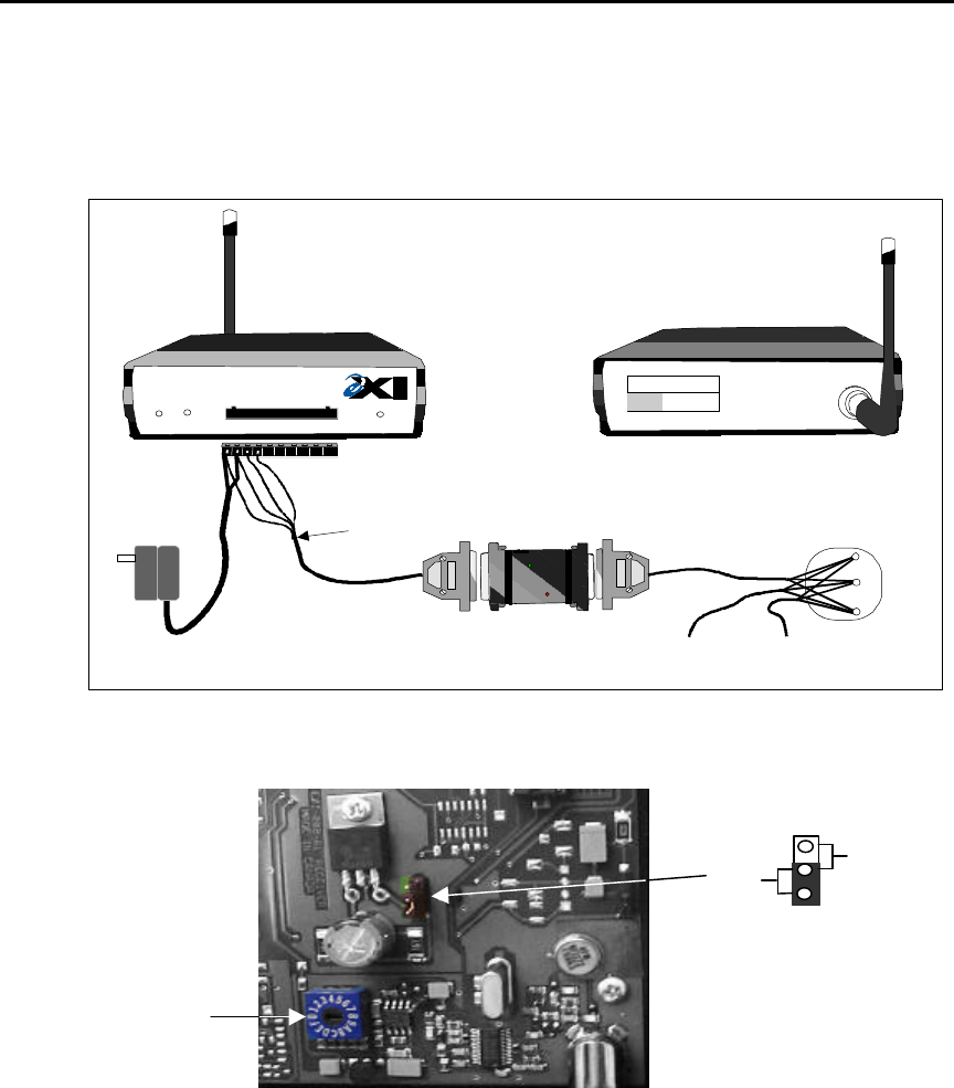
Figure 18 – HALO Receiver
5.8.1. Threshold Switch
The Threshold switch may be adjusted to increase or reduce the sensitivity of the Receiver and therefore
the range of detection of the Tag.
It is also used to remove some of the background noise as well as reduce interference from tags if the
controller is having trouble detecting tags. The result in the adjustment raises the RF field strength
threshold received from the tags in order to trigger the CPM into alarm (ie. from 25uV to 50uV) and
reduces the detection field range.
‘0’ = MAX sensitivity & ‘F’ = MIN sensitivity. The default setting is “2”.

EXI HALO Installation & Operation Manual 981-000003-000
EXI Wireless Systems 22 March 2000
Revision 2.0
5.9. RS-485 Interface Module (RIM)
Each HALO Controller, Receiver and Elevator Controller needs a RIM to interface to the RS-485 network that
terminates at the HALO Computer. The RIMs have a unique serial number that is associated to the locations on
the floor plans of the building, so that the computer can correctly show the location of an event occurring on
the system. Therefore, ensure that the correct RIM is installed at the corresponding locaton.
5.9.1. RIM LED Status
The 2 LED’s can be used to indicate a number of conditions to the installer. One LED is used to display
device status while the other LED is used to indicate network status.
During normal operation both LEDs should be “Steady On”.
LED behavior RED LED GREEN LED
OFF RIM not working, no power
source No network detected
FLASHING Poor communication due to loose
or reverse wiring on Weigand
lines.
Communication failure – no
network address.
ON STEADY Normal Operation. Power and
Weigand is good. Communication is good. Network
activity has been detected.
After both LEDs are “Steady On” test the RIM for communication by flashing a tag creating a TIC or TIF
alarm and the alarm created should be reported to the computer.
EXI HALO Installation & Operation Manual 981-000003-000
EXI Wireless Systems 23 March 2000
Revision 2.0
5.10. INSTALLING ELEVATOR CONTROLLERS
Only one elevator system should be installed per elevator car. When installing an elevator system it is best to
coordinate with the local Elevator Company to ensure that the elevator controls are not affected by the HALO
installation.
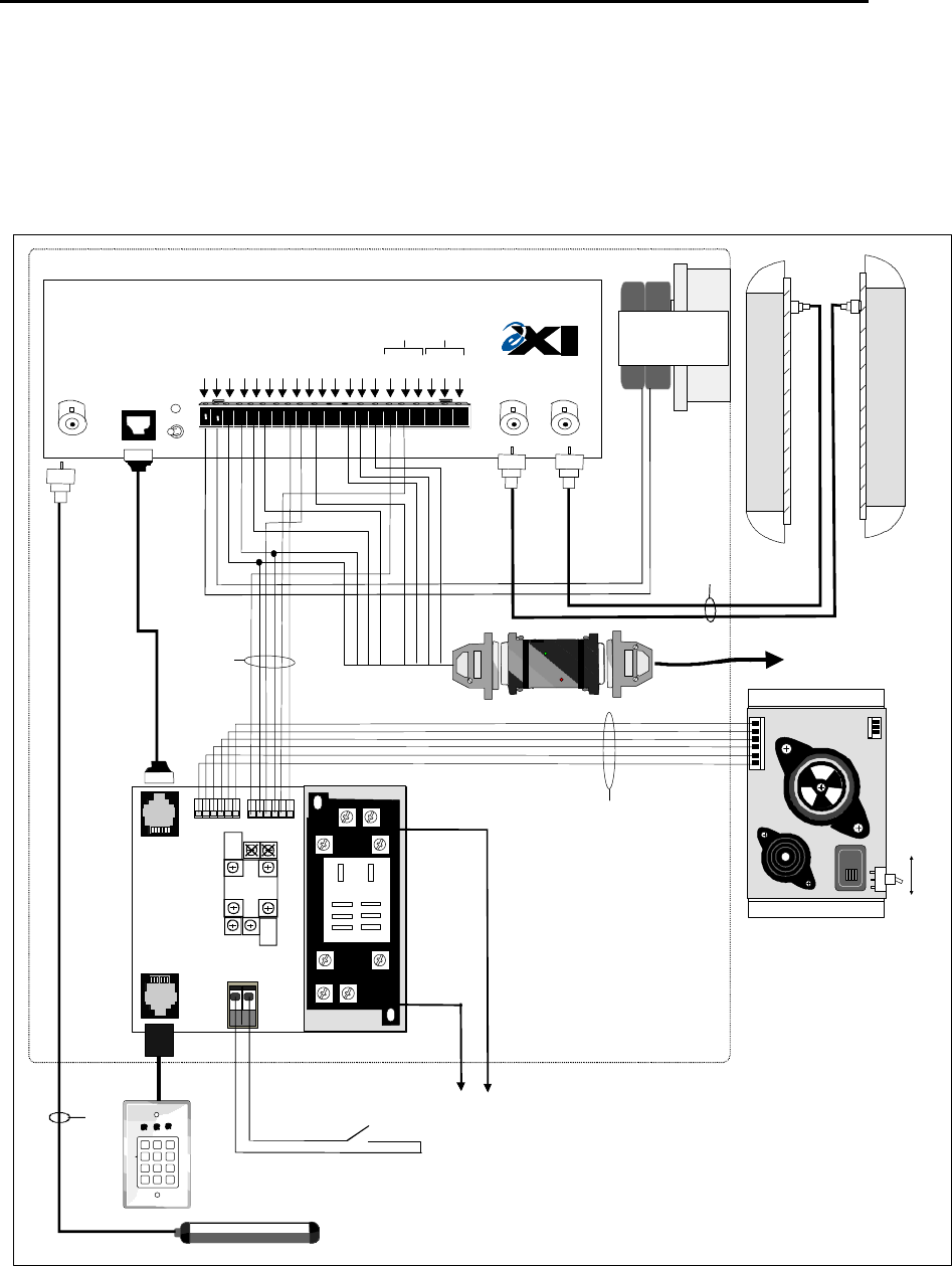
Figure 19 - Elevator Cabinet Detailed Wiring Diagram
RECEIVE
ANTENNA RBC
FCC ID# HE7MAX
TRANSMIT OUTPUT
SEA #1 SEA #2
Made in Canada . . with care Controller
by
Power
1 2 3 4 5 6 7 8 9 10 11 12 13 14 15 16 17 18 19 20
+24V DC Input
System Ground
+12V Ou 200 ma
System Ground
Weigand 0/Data
Weigand 1/Gnd
System Ground
MagOut 24V 200 ma
Door Switch In
System Ground
Unlock In
Override In
Strobe In
N.O
COM
N.C.
N.O
COM
N.C
Relay #1 Relay #2
Alarm In
OFF ON
R2 Controller
TC16/21 Cabinet
24 V (-)
24 V (+)
PS-24V
SRA-E #1 SRA-E #2
RX Antenna
1
Common #1
RED
BROWN
BLACK
BLUE
WHITE
EIM
126 A-7
AUDIBLE
ALARM
Factory Supplied
Audible Alarm
Cable
(15')
Test
Operate
Elevator Door
Disable
Factory Supplied
EIM Cable
Door Switch
(Closed - Door Closed)
WHITE
BLUE
GREEN
BROWN
BLACK
RED
15'
Factory Supplied
Coaxial Cables
(25')
Max 10A
110 VAC or 24VDC
HALO "Controller"
RBC/KEYPAD DOOR SW
DRY CONTACT
NC2
NC1
NO1
NO2
COM2
COM1
Not
Used
COM1 COM2
DO NOT USE
NO1 NO2
NC2
NC1
P2
P1
P4 P3
P5
Not
Used
GREEN
NC1
1 2 3
4 5 6
7 8 9
*0#Keypad
EIM
SIREN [-]
PREALARM [-]
TEST SWITCH
POS 12V
KEY SWITCH
GREEN LED [-]
RIM To RS-485
Network through
Elevator Travel
Cable
RS-485
Weigand
BROWN
GREEN
BLACK
BLUE
WHITE
RED
YELLOW
GRAY
EXI HALO Installation & Operation Manual 981-000003-000
EXI Wireless Systems 24 March 2000
Revision 2.0
5.10.1. CONTROLLER CABINET INSTALLATION
Mount the HALO Elevator Controller Cabinet inside the elevator car. A suitable location for mounting the
cabinet would be bolted securely with locking hardware above the ceiling tile of the elevator car, or on top
of the elevator car roof. The cabinet may be mounted in any orientation, depending on what the space
allows. Ensure that the cabinet can be opened easily to allow you to make the various connections
necessary, and to be able to make adjustments to the controls within the Elevator Controller inside the
Cabinet.
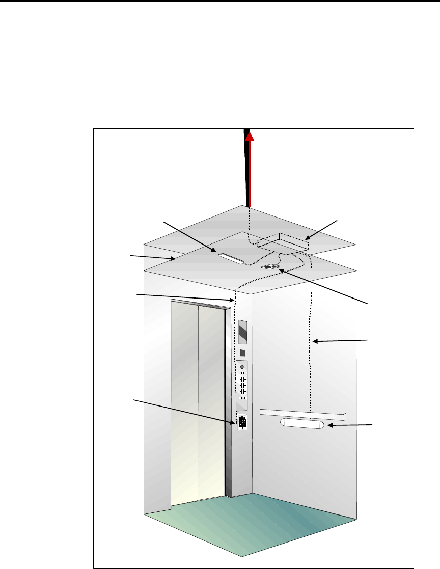
Figure 20 - HALO Elevator Controller Installation
Should any extra holes be required to mount the cabinet, ensure that no steel cuttings fall into the cabinet,
as this may cause the system to malfunction. A 120 VAC duplex plug is required in the proximity of the
cabinet so as to be able to supply power to the cabinet.
The RIM is built into the Cabinet. With the assistance of the Elevator Company, the three wires from the
RS 485 side of the RIM should be pulled to the Elevator Control Room, or Penthouse, from which they
Controller
Cabinet
(Bolted on top of
elevator roof
or on ceiling )
Keypad
SRA-E
Antenna
(2)
Antenna
Cable
Keypad
Cable
RX Antenna
Dropped
Ceiling
Audible
Alarm
Module
RS-485 Connection
to Elevator Control
Roomthrough
travel cable
EXI HALO Installation & Operation Manual 981-000003-000
EXI Wireless Systems 25 March 2000
Revision 2.0
should be routed back to the HALO RS-485 Network. It is highly recommended that you employ an RS-
485 Repeater, available from EXI, in the Elevator Control Room to separate the Elevator connections from
the main HALO network. The Repeater isolates the noise that may be picked up during elevator operation,
boosts the RS485 signal, and reduces the total capacitance on the network to ensure reliable operation.
5.10.2. LOCATION FOR SRA-E EXCITER ANTENNAS
One of the most important aspects of the entire installation is the correct positioning of the SRA-E
Antennae. The two antennae are to be mounted under each side rail in the center position of the elevator
sidewall, opposite each other. This is the recommended location and you may improvise depending on the
design of the elevator car.
• Place the SRA-E template, or an antenna, on the center of the elevator wall, at least 1” below the
handrail. Use the screw holes on the template to mark the location of the mounting screws and hole for
coax cable entry, and drill holes as required.
• Remove the cover from the SRA-E, thread screw anchors (not provided) into the elevator wall to the
correct depth, insert the screws into the SRA-E nylon foot, then thread the screws into the anchor
receptors so the SRA-E mounts securely to the elevator wall.
• Repeat this procedure for the opposite side.
• Once the Antennae are mounted, run the Antenna Coaxial cables down from the Controller Cabinet on
each side of the car. Draw the cables through the ½” holes on the nylon foot on each side and connect
the mating coax fitting on each of the SRA-E antenna. Then replace the cover on each antenna.
Figure 21 - SRA-E Installation
Handrail
Elevator Wall
SRA-E
Front View
Top
Cross-section

EXI HALO Installation & Operation Manual 981-000003-000
EXI Wireless Systems 26 March 2000
Revision 2.0
5.10.3. Elevator Receive (RX) Antenna
Locate a suitable position for the RX Antenna. Should the elevator have a dropped ceiling which is
accessible, this area may be used for the antenna provided that the insulation between the antenna and the
cab is not treated with a foil backing. Should such a foil backing be present, you may strip the foil from the
fiberglass and discard it. Do not locate the RX Antenna above a metal or metalized plastic egg-crate
ceiling, as this would render it ineffective.
It is recommended that the RX Antenna be mounted in the horizontal plane, parallel to the elevator floor, to
reduce noise pick-up.
• Place the RX Antenna on the surface to which it will be placed and mark the point through which
the coax cable will exit.
• Drill a suitable hole at the location marked and place a grommet into this hole to protect the coax
cable from getting frayed.
• Clean the surface where the antenna is to be mounted with alcohol or similar cleanser. Remove the
protective strip from the double-sided tape at the back of the RX Antenna and mount the antenna
to this surface.
• Thread the coax cable through the grommet and connect it to the Controller within the HALO
Elevator Cabinet.
5.10.4. Audible Alarm Module
The Audible Alarm module can be mounted on the elevator “COP” panel. If the elevator car has an egg-
crate style ceiling, a dropped ceiling or a lighting valance, the Audible Alarm module may be mounted in
this location as well. An open area should be chosen so as to allow the alarm sounds to be clearly heard.
The switch on the module is to select between “Exciter Field Test Mode” and “Normal Operation”. With
“Exciter Field Test Mode” selected, the beeper on the module will sound momentarily each time a valid
response is received from a Transponder. This helps to determine the outside limits of the detection field,
and whether any null areas exist within this field.
• Identify the location where the Audible Alarm Module will be located, ensuring that easy access can
be gained for the 6-conductor cable that connects it to the Elevator Cabinet.
• Secure the Audible Alarm Module with the metal self-tapping screws provided, to the elevator car
ceiling or the wall above a suspended ceiling, or the “COP” panel.
• Connect one end of the Audible Alarm Cable to the module and the other end to the connector marked
“P4” on the Elevator Interface Module (EIM) within the cabinet.
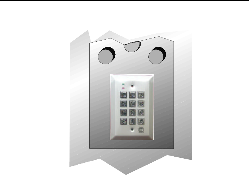
5.10.5. Keypad
It is recommended that the Keypad be mounted on the elevator “COP” panel at a height that allows easy
access for the nursing staff who must enter a 3-7 digit code to enable the Bypass mode. If there is no spare
space available on the “COP” panel, the Keypad may be mounted in a suitable location on the elevator
wall.
• Cut a hole in the “COP” panel to accommodate the rear of the Keypad assembly that will be inserted.
• Drill holes for the screws, using the Keypad as a template to locate the correct positions for these
holes.
• Thread the Keypad Cable supplied through the “COP” panel and up to the cabinet.
• Plug one end of the cable to the Keypad and the other end to the EIM within the cabinet.
EXI HALO Installation & Operation Manual 981-000003-000
EXI Wireless Systems 27 March 2000
Revision 2.0
• Secure the Keypad to the “COP” panel.
Figure 22 - Elevator Keypad Installation
5.10.6. “Door not Closed” Contact
In order for the system to operate correctly, the contacts supplied with the elevator controls that indicate
when the elevator door is open or closed, have to be monitored by the HALO Elevator Controller. These
contacts have to be normally open when the doors are open, and closed when the doors are closed. If such a
pair of contacts is not available, a suitable set of contacts will need to be installed, as without these the
HALO Elevator Controller will not shut off when the elevator doors are closed.
• Run a pair of wires from the Form-C contacts on the EIM within the cabinet to the elevator door open
control contacts within the elevator control panel.
• If necessary, run a pair of wires from the elevator control “Fire Condition” contacts to the “System
Override In” and “Common” inputs of the Elevator Controller within the cabinet.
5.10.7. Door Control and Fire Alarm Supervision
The elevator doors are held open in alarm conditions so that the elevator cannot move. The EIM within the
cabinet has Form-C Normally Open (N/O) and Normally Closed (N/C) contacts that can be used to control
the door.
In the event of a fire alarm, a “system override” input is available on the Elevator Controller within the
cabinet. When this input is shorted to ground, the system, and the door control function, will be inhibited so
as to render the elevator operational. Only a few elevators require this function to be implemented as most
elevator systems have their own “Fire Condition” operating mode that seizes control of the elevator during
a fire condition. If in doubt, check with the elevator company.
• Run a pair of wires from the Form-C contacts on the EIM within the cabinet to the elevator door
control contacts within the elevator control panel.
• If necessary, run a pair of wires from the elevator control “Fire Condition” contacts to the “Override
In” and “Common” inputs of the Elevator Controller within the cabinet.
CLOSECLOSE
DOORDOOR OPENOPEN
DOORDOOR
LOBBYLOBBY
EXI HALO Installation & Operation Manual 981-000003-000
EXI Wireless Systems 28 March 2000
Revision 2.0
5.10.8. System Adjustment and Testing
Upon completion of the installation, follow this procedure for testing the system operation:
• Power on the system, and set the Test Switch on the Audible Alarm Module to “Test”.
• Expose a Transponder within the elevator cab. The pre-alarm beeper will beep as the system senses the
Transponder within its field. The closer the beep intervals, the greater the sensitivity of the
Transponder to the exciter field. Try various orientations and positions of the Transponder within the
cab (don’t forget the floor!), to ensure adequate coverage.
• In the event that the field appears to be too strong, indicated by the fact that a Transponder is sensed
well outside the elevator cab, adjust the “Range Adjust” setting within the HALO Controller located
inside the Cabinet to optimize the exciter field (see Threshold setting instructions for HALO Controller
in Section 5.7.1.5)
• Set the Tests Switch on the Audible Alarm back to Normal Operation.
• Enter the elevator with a Transponder, which should immediately trigger a pre-alarm beeper tone
lasting for 11 seconds. The Alarm light on the Keypad will flash momentarily during this time.
• Leave the elevator cab within the 11 seconds, or place the Transponder within its metal foil bag
(making sure it is tightly sealed). The system should reset itself and release the doors for normal
operation at the end of the 11-second pre-alarm period.
• To test the Bypass function, expose the Transponder within the cab. The pre-alarm beeper will trigger.
Enter “1938” on the Keypad, which should now allow normal operation of the elevator.
• Test the “full alarm” mode by exposing a Transponder within the cab for greater than 11 seconds.
After the pre-alarm beeper is heard for the 11-second duration, a loud alarm will begin. If the
Transponder is removed from the cab during the full alarm period, the system should reset itself within
6 seconds.
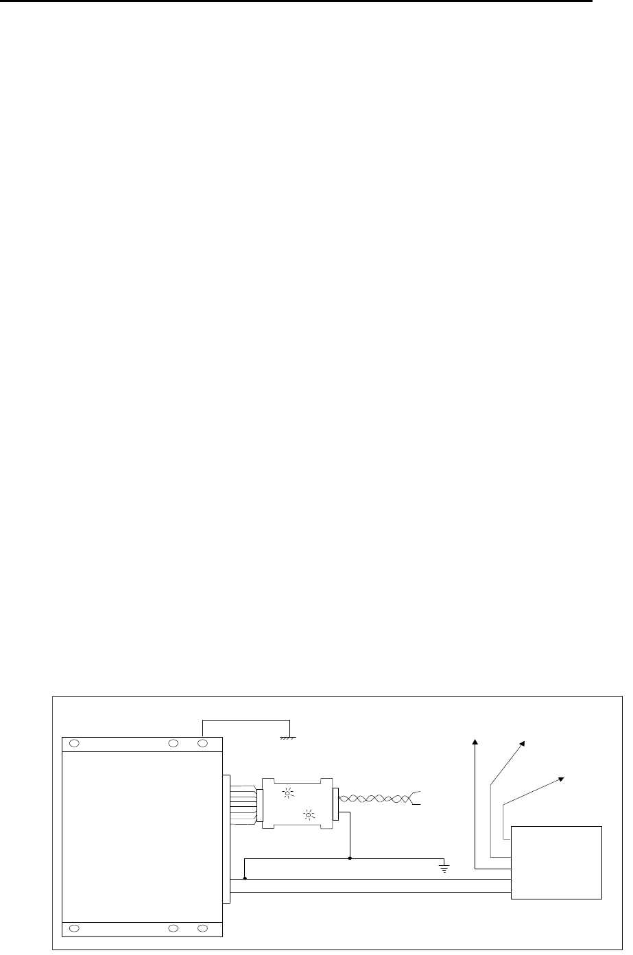
5.11. SYSTEM GROUNDING CONSIDERATIONS
The difference between successful installations that are free of noise versus those that are plagued with
unreliable operation is often poor grounding of the system elements. Ensure that no ground loops exist in the
system, and that all the system components are adequately grounded.
The figure below shows ground requirements for Controllers in the system. The chassis of the Controller is
connected to the building ground. The Receiver is also and the power supply and RS-485 grounds are
connected together for both the Controller and Receiver so that the signal at the RS-485 interface is referenced
correctly.
Controller
(Top View)
Device 1 Central
Power
Supply
CPS-24
To
Device 2 To
Device 3
To
Device N
RS485
AWG14 (Ground) which
runs through entire
ROAM II Network
-
+
20-pin
Connector
Building
Ground
RIM
RS485
+
-
EXI HALO Installation & Operation Manual 981-000003-000
EXI Wireless Systems 29 March 2000
Revision 2.0
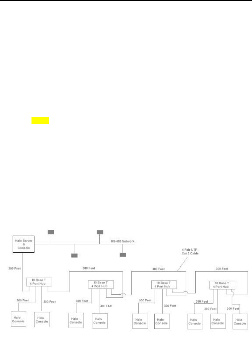
6. PC Networked Installation
(Must have a dedicated Ethernet)
10BASE-T CABLING:
• Maximum allowable distance per segment is 100 meters.
• Supports 10Mb/s transmission rate.
• Uses a Star Topology.
• Unshielded Twisted Pair Category 5 cable recommended.
• Two Computers (10 Base T NICs) may be directly attached to each other without a repeating hub,
provided the distance between the two computers is less than 100 meters. In this case a special
“Crossover Cable” is required that attaches transmit pair of one station to the receive pair of the other
station, and vice versa. When using a hub the cross over function is performed inside the repeating
hub.
NOTE: It is recommended to use a hub to connect two Computers.
• ADVANTAGES: a) Star Wiring topology supports easier maintenance & troubleshooting.
Provides a modular approach to network construction.
b) Inexpensive cabling & easy to install.
c) Ethernet packets are routed more effectively & efficiently than the
traditional Bus design.
• DISADVANTAGES: 10Base2 supports longer segment lengths.
• 5-4-3 RULE: With 10Base-T wired networks, a maximum of 5 wiring segments is allowed between
any connected computers within the LAN and only 3 of the segments can be populated with consoles
or server.
• Therefore the maximum distance between two computers is 500 meters.
• 10Base-T cable is susceptible to EMI. Try to keep cables away from Elevator motors, florescent
lighting fixtures, uninterruptible power supplies, & other sources of EMI. Coiling up cables can also
cause interference.
EXI HALO Installation & Operation Manual 981-000003-000
EXI Wireless Systems 30 March 2000
Revision 2.0
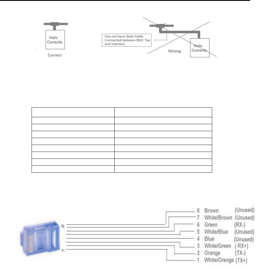
RJ-45 Connector
The 10Base-T media system uses two pairs of wires, which are terminated in an eight-position (RJ-45 style)
connector. This means four pins of the eight-position connector are used. The following table shows the RJ-45
connector pin assignments.
PIN NUMBER SIGNAL
1TxD+ (Transmit Data)
2TxD- (Transmit Data)
3RxD+ (Receive Data)
4Unused
5Unused
6RxD- (Receive Data)
7Unused
8Unused
EXI HALO Installation & Operation Manual 981-000003-000
EXI Wireless Systems 31 March 2000
Revision 2.0
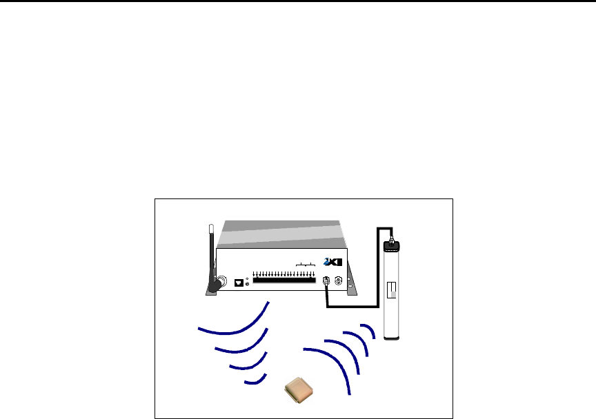
7. Theory of Operation
The EXI HALO system uses Radio Frequency waves for communications between the HALO system components
and the Tags. The HALO Controller continuously emits a 307 kHz RF frequency via the Exciter Antenna, setting up
a field in its local area. When a Tag enters this field, a Radio Receiver within the Tag senses the 307 kHz RF field
and transmits its identification information to the HALO Controller using a low level Radio Signal at frequency of
434 MHz.
Figure 23 - Controller Operation
7.1. Tag Communications
All Halo tags will transmit their serial number whenever they first enter a field created by a HALO controller.
We refer to this type of communication as a TIF (tag in field) for the purpose of brevity. The HALO controller
is able to communicate directly with one Tag even if there are multiple Tags in the field since the
communication is bi-directional. The Tag will not retransmit its serial number again until it is reset by the
controller or out of the field for at least 6-18 seconds.
If a Tag is able to receive communication from 2 different controllers in the case of field overlap, it will try to
respond to both controllers thereby inhibiting any alarms. Each controller will see Tag communication when it
doesn’t expect it and report it as noise. While in the field, the Tag continues to communicate with the controller
but in a limited way in order to conserve battery power. Because of this limited communication, the controller
has no way of knowing when each Tag leaves the field. It can only tell that there is still at least 1 Tag in the
field. It takes 6-18 seconds of all the Tags being out of the field before the controller will recognize that the
field is empty.
Some types of tags will also transmit their serial number when certain events occur to the tag. We refer to this
transmission as a TIC (tag initiated communication). All HALO Controllers and Receivers can pick up these
transmissions. P-Tags transmit a TIC whenever the Tag is first removed from the body and again after variable
intervals, the longest being 4 minutes. The Tag has to be put back on the body for 10 seconds to reset it before
it will repeat its pattern.
7.2. HALO System Communications
HALO Controllers and Receivers connected to the network report any events to the HALO PC Console, in
addition to responding to such events locally. A HALO Controller, if configured as such, will independently
control its associated door in the presence of a Tag at its door, in addition to reporting such an event to the
HALO PC Console. This ensures that local control and security is maintained regardless of the state of the
HALO network or PC Console. All devices that are connected to the RS485 communications bus are fully
supervised such that any device failure is reported at the console immediately
RECEIVE
ANTENNA RBC
FCC ID# HE7MAX
TRANSMIT OUTPUT
SEA #1 SEA #2
Made in Canada . . with care Controller
by
Power
1 2 3 4 5 6 7 8 9 10 11 12 13 14 15 16 17 18 19 20
+24V DC Input
System Ground
+12V Ou 200 ma
System Ground
Weigand 0/Data
Weigand 1/Gnd
System Ground
MagOut 24V 200 ma
Door Switch In
System Ground
Unlock In
Override In
Strobe In
N.O
COM
N.C.
N.O
COM
N.C
Relay #1 Relay #2
Alarm In
OFF ON
EXI ELECTRONIC SYSTEMS
Winnipeg, Manitoba (204) 788-1696
Made in Canada
PRODUCT
MODEL NO.
SERIAL NO>
ROAM II/TAGRRR
SEA-M
1118
HALO Controller
RX
Antenna SRA
Exciter
Antenna
434 MHz 307 KHz
Transponder
R2 Controller
EXI HALO Installation & Operation Manual 981-000003-000
EXI Wireless Systems 32 March 2000
Revision 2.0
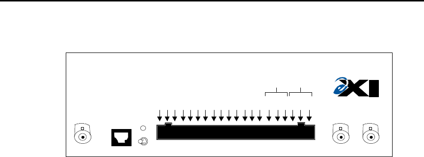
7.3. HALO CONTROLLER
Figure 24 – Halo Controller Front Panel
The HALO controller handles all communication with the Tags, provides audible and visual indicators of
what state its in and prevents egress when necessary. This device is fully capable of operating in stand-
alone mode although it does provide for communication to several different types of central reporting
systems. The front panel provides easy access to a number of different output formats as well as allowing
inputs to alter some of its automatic functions as necessary. Local alarm and bypass annunciation is
available through the DKX Keypad.
The Tag serial numbers as well as status information is output in Weigand format on 2 of the output pins.
This is a standard format used by many Card Access Systems. The MagOut line will engage a Magnetic
Door Lock when Tag’s are detected in the field. Due to NFPA 101 regulations being adopted in many
locations, it may be mandatory to provide an automatic door release with 15 seconds after a door has been
locked up. The controller provides 2 Form-C dry contacts rated at 1 Amp @ 30VDC. They will provide
normally open or normally closed contacts and will change state to indicate the 2 different alarm conditions
– Tag In Field (TIF) and Tag Initiated Communication (TIC). These Relays can be used to turn on remote
signaling devices such as:
- Nurse Call system annunciators (should have latching function)
- EXI model “SSM” 2-zone audible alarm with selectable tone sequences
- EXI model “ANN-6L” Audible-Visual 6-zone, LED type non-supervised Annunciator
See Appendices for details.
The HALO controller uses the Door Switch input to disable alarm reporting, when the door is closed. This
is known as the Nurse Saver Feature. Although Tags are still detected and reported to a central system, no
alarms are annunciated until the door opens. At that time, all the Tags are re-read by the controller so that
only the Tags that are still in the field will cause an alarm. The door switch is also useful during bypass as
the controller will detect the door opening and then terminate the bypass as soon as the door closes. In the
event that a Tag is detected at the door with the door being closed, and the Tag remains at the door for a
period exceeding 70 seconds, an Alarm condition is created. This is known as the Loiter Feature,
preventing a patient from waiting at the door for an opportunity to exit when the door is bypassed, or
otherwise opened.
A remote system or switches can use three input lines to alter the normal operation of the controller.
Unlock In provides a temporary release of the door, for a system override such as that from a fire alarm
control.. Alarm in will cause an immediate lockup of the door with the local and remote alarm
annunciators on. Override In will disable the controller so that no tags are read and nothing will be
reported to the Host computer. Shorting the appropriate line to system ground will activate the function.
RECEIVE
ANTENNA RBC
FCC ID# HE7MAX
TRANSMIT OUTPUT
SEA #1 SEA #2
Made in Canada . . with care Controller
by
Power
1 2 3 4 5 6 7 8 9 10 11 12 13 14 15 16 17 18 19 20
+24V DC Input
System Ground
System Ground
Weigand 1/Gnd
MagOut 24V 200 ma
System Ground
Override In
N.O
N.C.
COM
Relay #1 Relay #2
Alarm In
OFF ON
R2 Controller
EXI HALO Installation & Operation Manual 981-000003-000
EXI Wireless Systems 33 March 2000
Revision 2.0
Controller Input Switch State Result
Closed
Unlock In
Open
Closed Force Door Lock
Open Normal Operation
Controller Disabled
Override In
Normal Operation
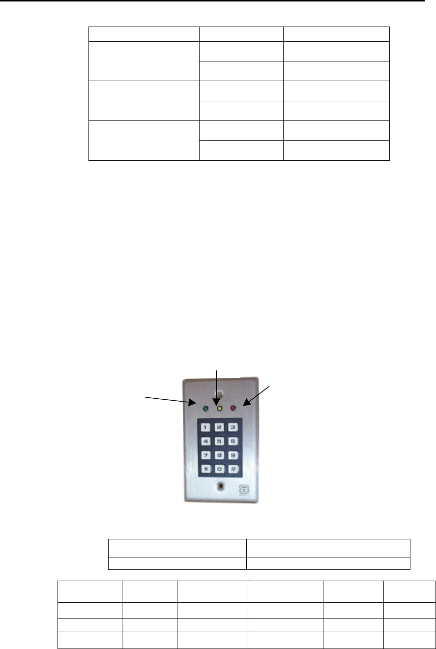
7.4.KEYPAD
The Keypad provides the user with four separate functions.
Local audible and visual alarm,
Allows bypass function,
Reset the alarm when the controller is in continuous alarm mode, or reset the bypass sequence
Controller status indication via the keypad LEDs.
member needs to be able to initiate a bypass function from either side of the door, there will have to be two
Keypads installed. A “Y” Cable adapter is available to easily connect the two keypads to the door controller.
Figure 25 – Keypad Indicator Functions
INDICATORS STANDBY
MODE ALARM MODE BYPASS
MODE (1938) RESET
MODE (1939) READER
MODE
YELLOW ON ON ON ON ON
RED OFF ON (FLASHING) ON (FLASHING) X=don’t care OFF
GREEN OFF OFF ON (FLASHING) X=don’t care ON
JUMPER J1 settings on Halo
Controller Position 2 for DKX Keypad operation.
Position 1 for RBC Keypad operation.
Standby:
Yellow
Bypass:
Green
Alarm:
Red

EXI HALO Installation & Operation Manual 981-000003-000
EXI Wireless Systems 34 March 2000
Revision 2.0
BYPASS is used to move Tags through a controlled area without triggering an alarm. The GREEN light will
alternately flash with the RED light when the unit is in Bypass.
During Bypass mode:
• you have 8 seconds to bring the transponder into the field after entering the Bypass code on the
Keypad, or the system will re-arm
• once the Tag is in the field, bypass will end 8 seconds after all Tags leave the field or the door
closes, or the maximum Bypass time is exceeded. Bypass can also be terminated by a Reset from a
Keypad.
• once you enter the field you have 90 seconds to pass through the detection zone
• if you passed through within 90 seconds the system will rearm within 8 seconds or the system will
go into alarm after 90 seconds.
• Any Tags still in the detection area 10 seconds after the door closes will be reread so they can
trigger an alarm if necessary.
RESET request will turn off the TIC-alarm relay or terminate the Tag Alarm if the Continuous Alarm mode
was selected and there are no more Tags in the field. It takes the controller 6 seconds to recognize that the Tag
has actually left the field.
STANDBY: The YELLOW light indicates the system power supply is ON.
ALARM: The RED light flashing indicates that the controller is in Alarm. A beeper also provides an audible
alarm indication when this light is on. If the door is open, the Alarm light and beeper will beep with a long ON
time and the Alarm Relay will turn ON. This alarm will also be reported at the HALO PC Console.
Pre-Alarm (Nurse Saver Feature)
If the door is closed and there is a door switch installed, the Alarm light and beeper on the keypad
associated with that door will turn on and off with a short ON time, when a Tag enters the field.
This is a known as a pre-alarm condition as a bad Tag is in the detection area but the door hasn’t
opened. Such an event is indicated at the HALO PC Console by a change in the appropriate floor
button, and the device icon, from their normal color to yellow.
Loiter Alarm
If the Tag remains in this field for 70 seconds, a “Loiter” alarm is reported at the HALO PC Console
and the associated floor button, and device icon, turn red.
READER MODE: A constant GREEN light indicates that the associated Controller is in “Reader Mode”. That
is, the HALO system software has disabled that particular Controller for normal Tag communications, and has
enabled the Controller to detect the presence of Tags not in the Database inventory, for the purpose of adding
such Tags into the Database inventory.
The Keypads allow a unique programmable code for both reset and bypass. The Keypads come preset with
default codes of “1938” for Bypass and “1939” for Reset. Refer to Keypad programming sheet for
instructions on how to change these codes.
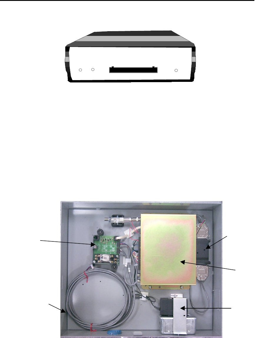
EXI HALO Installation & Operation Manual 981-000003-000
EXI Wireless Systems 35 March 2000
Revision 2.0
7.5. HALO RECEIVER
Figure 26 - HALO Receiver Front Panel
The HALO Receiver is used for detecting “off body” or Tag Initiated Communication (TIC) conditions, within
a building. The Receiver does not have the capability of generating an Exciter Field, as does the HALO
Controller.
7.6. ELEVATOR CONTROLLER
Although an Elevator Interface looks like a controller placed inside a box with added sirens and switch inputs,
with the elevator firmware installed in the controller chassis, the Interface behaves much differently. This unit
requires a door switch be installed in order to operate properly. With the Elevator Door disable, the unit will
prevent the elevator door from closing during Pre-Alarm and Full-Alarm. The Elevator Interface can be
bypassed with a Keypad, if a Tag is present in the Elevator. Bypass is used to take Tagged patients onto the
elevator. There is no local annunciation of a TIC alarm however the serial number is sent to the HOST
computer for remote annunciation.
Figure 27 - Inside the HALO Elevator Cabinet
7.6.1. Pre-Alarm
The Elevator Interface enters a Pre-Alarm state as soon as it detects a Tag in its field. The flashing Alarm
light on the Keypad and the Pre-alarm beeper indicate this state locally. This alarm will end when the
user requests a bypass or 6 seconds after all Tags leave the field. After 11 seconds of Pre-Alarm, the Tags
R2 RECEIVER
DATA
COMM.
Made in Canada . . with care
12/24 VDC
GROUND
DATA 0
DATA 1
N/O 1
COM 1
N/C 1
N/O 2
COM 2
N/C 2
POWER RELAY
1 2 3 4 5 6 7 8 9 10
RIM
HALO
Controller
24V DC
Converter
Keypad
Cable
EIM

EXI HALO Installation & Operation Manual 981-000003-000
EXI Wireless Systems 36 March 2000
Revision 2.0
are reread. If there are any non-bypassed Tags detected, Full-Alarm will start and the HOST computer will
report a Tag Alarm.
7.6.2. Full-Alarm
Full-Alarm is indicated locally by a steady Alarm light on the Keypad and the Full-Alarm siren. This
alarm will continue until all the Tags leave the detection field or the user requests a Bypass.
7.6.3. Elevator Bypass
Bypass is initiated locally with the Keypad. The Bypass will only apply to the Tags that are currently in the
field. Any new Tags detected after the Bypass request will cause the Pre-Alarm to start again. If there are
no Tags in the field at the time of bypass, there will be nothing to Bypass. If any Tags are bypassed, the
Bypass light on the Keypad will be on and will remain on until all the bypassed Tags have left the elevator.

EXI HALO Installation & Operation Manual 981-000003-000
EXI Wireless Systems 37 March 2000
Revision 2.0
8. HALO Console (Single Station)
For Networked version see Halo Networked Dealers Manual: 984-000003-000
The HALO Console is a Pentium based Host Computer with a Color Monitor, a Keyboard, mouse, and Speakers for
audible feedback. A ZIP drive is built into the computer to allow for periodic backup of data. The ZIP disk is
removable, allowing for off-site archiving of the backed-up database. The computer also has a built-in RS-485
Interface card to which the HALO system components are connected.
The Color Monitor comes in two flavors and may be a CRT based 17” monitor or a 15” LCD Flat Panel. An
Uninterruptable Power Supply (UPS) is highly recommended to ensure that the computer is not affected in the event
of AC brown-outs, or in the case of loss of AC power.
The Host Computer runs the HALO Application Software that provides the following major user functions:
§ Management of the database that stores the identities of all the system components and Tags that
are deployed within the system
§ Management and storage of logs of all the events that occur during use
§ Annunciation of any of the alarm conditions that may exist, showing location of such an alarm
condition in a graphical format overlaid over the floor plan of the building in which the system is
installed
For stand-alone HALO systems that only require localized alarm and control, the Host Computer may not be
required. The computer comes pre-loaded with the Microsoft Windows 98 Operating System, and the EXI HALO
Console. The EXI HALO Console application is the primary interface for the user, annunciating Alarm information
at the same time as logging all activity on the network. The Halo system has three separate security access levels,
namely “USER”, “SUPERVISOR” and “DEALER”.
As an installer, you will be interested primarily in the Dealer mode for installation purposes, and the other modes for
training purposes. When the computer is first powered up, the “User” screen is automatically launched, and the
default floor plan will be seen. Pressing “ALT” “D” simultaneously accesses dealer mode, while the Supervisor
mode requires “ALT” ”L”. To exit the HALO Console, press “ALT” ”Q” twice while in Dealer mode and type in
“Dealer” for the user and password fields.
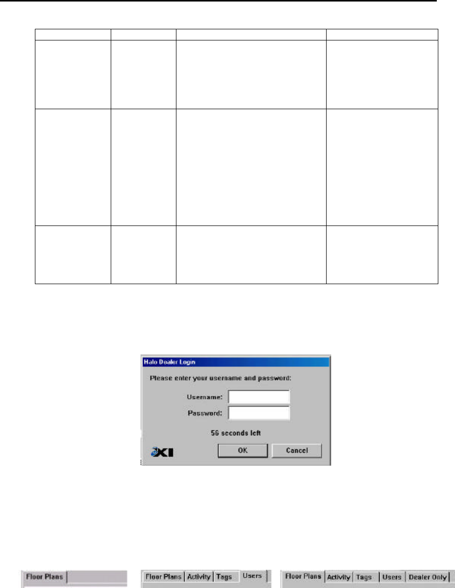
EXI HALO Installation & Operation Manual 981-000003-000
EXI Wireless Systems 38 March 2000
Revision 2.0
Figure 28 - Buttons for Dealer and Supervisor modes
Both Dealer and Supervisor modes require a User Name and Password for access. Upon entering the correct
information in the panel as shown below, the HALO Console enters the appropriate mode.
Figure 29 - Dealer Mode User/Password Prompt
The User mode only has access to the Floor Plan screen, while the Supervisor mode has access to system Activity,
Tag management and Users management screens. The Dealer mode has an additional Dealer Only screen that is
used to add floor plans and network devices, in addition to being able to set system parameters and carry out simple
diagnostics.
USER SUPERVISOR DEALER
Figure 30 – Available Screens Depending on Access Level
Level Password Functions Access Management
User Yes Admit Patients
Discharge Patients
Accept/Silence alarms
Toggle between floor plans (No
Password required)
Access controlled by
Supervisor or Dealer level
users
Supervisor Yes All user functions
Manage user list
Assign usernames and passwords
View and annotate activity logs
Add/Delete/Edit tags from fleet
Initiate System Data Backups
Print logs
Exit the Halo system
The first Supervisor is
setup by the installing
dealer. This Supervisor
may add more assigned
supervisory access.
Dealer Yes All user/Supervisor functions
System Diagnostics
System modifications
Importing floor plans
Controlled by Dealer and
EXI
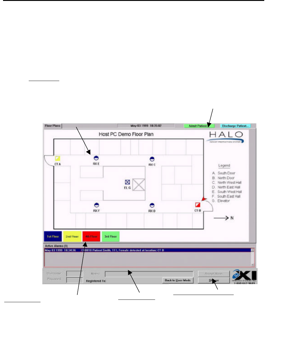
EXI HALO Installation & Operation Manual 981-000003-000
EXI Wireless Systems 39 March 2000
Revision 2.0
Floor Plan area.
Controllers shown as half-filled square icons
Receivers shown as half-filled circular icons
Elevators shown as square icon with “X’
Blue: Normal, Yellow: Pre-Alarm condition,
Flashing Red: Full Alarm condition
Arrow points at device(s) corresponding to selected alarm in
Active Alarm field
Floor Plan Buttons
Green: Normal
Blue: Indicates that the cursor is positioned over button
Yellow: Indicated Pre-alarm condition on floor
Red: Alarm condition on this floor
Active alarms field
Red: Normal alarm color
Blue: Selected alarm
Patient Admit and Discharge buttons
Alarm Silence and Accept field.
Normally grayed characters.
“Silence” button is active upon selecting an alarm from the
Active Alarm field.
“Accept Alarm” button is active after valid Username and
Password are entered.
8.1. Computer Display Conventions
The computer displays various types of information, which is color coded to differentiate between the Dealer,
Supervisor and User modes. In addition, the “Icons” that display the locations of the various system
components such as the Controllers and the Receivers, and the on-screen “buttons” may also change color to
indicate their status.
Figure 31 - HALO Console User Screen
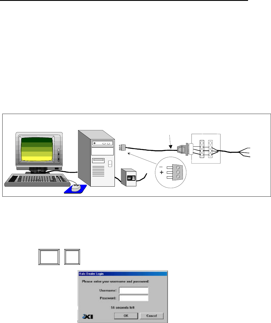
EXI HALO Installation & Operation Manual 981-000003-000
EXI Wireless Systems 40 March 2000
Revision 2.0
Alt D
8.2. Connecting to the Host Computer
Unpack the Host Computer and the Monitor and place them in approximately their permanent location. If a
UPS has been supplied, place the UPS next to the Computer. Ensure that there is a suitable power outlet in the
vicinity of the location, and connect the UPS to this output. Attach the Monitor Cable, Keyboard, Mouse and
the Power Cable to the Computer, and connect the Power Cable plug to the output of the UPS.
Connect the 3-pin RS-485 connector on the Network Cable to the RS-485 Interface Card socket at the back of
the Computer, and connect the DB-9 connector at the other end of the cable to the PC Terminator Box. The use
of a Terminator Box is not necessary, but is highly recommended so as to enable relocation of the Computer
without having to also relocate the RS-485 line that runs to the networked devices. In the event that the PC
Terminator Box is not used, the 3-pin RS-485 connector can be spliced directly to the RS-432 network line,
and the DB-9 connector may be discarded.
Figure 32 - Host Computer Connections
Turn the UPS power switch to ‘ON”, and then power up the computer. After some self-tests, the Microsoft
Windows 98 splash-screen will be seen followed by the HALO Console default User screen.
8.2.1. Navigating the Dealer Screens
Press on the computer keyboard simultaneously.
Type in the “User name” and “Password” at the prompt (both fields are the word “Dealer”).
The default Dealer level screen will appear as shown below, showing all the floor plans present in the
system.
PC Terminator
Box
PC to
Network Cable
RS-485 Connector
(To Halo Network
Controller Output) DB9
Com
Enlarged
View
Factory
Supplied
To all
RIMs
(TAP Boxes)
RS+ (Red)
GND (Grn)
RS- (Blk)
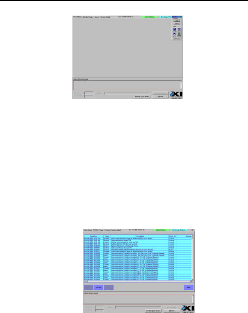
EXI HALO Installation & Operation Manual 981-000003-000
EXI Wireless Systems 41 March 2000
Revision 2.0
Figure 33 - Dealer Floor Plan Screen
Clicking on the “Activity” tab accesses the Activity screen, which lists all events that have been logged
in the system. The maximum number of events stored is 14,000 activities, after which any additional
events will displace the very first event logged on a First-in-First-out basis.
Figure 34 - Dealer "Activity" Screen
The “Tags” screen contains the details of all Transponders that have been assigned to the system. This
screen allows the addition or deletion of Tags, and entry of patient information for Tags that are assigned to
a patient.
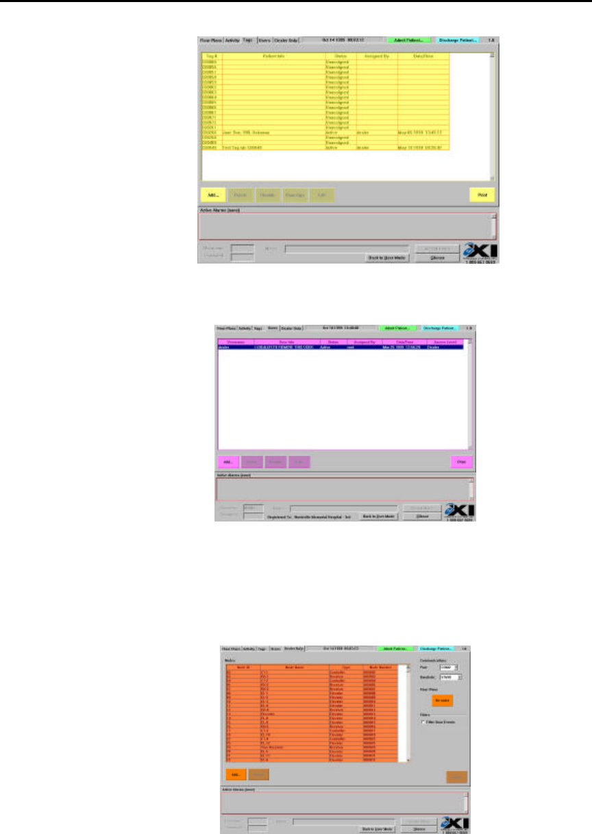
EXI HALO Installation & Operation Manual 981-000003-000
EXI Wireless Systems 42 March 2000
Revision 2.0
Figure 35 - Dealer "Tags" screen
The next tab selection is the “Users” screen. This allows for new Supervisors and Users to be entered.
Figure 36 - Dealer "User" Screen
The “Dealer Only” screen contains a list of all devices present on the HALO network, and allows the
addition and deletion of devices as well as the setting up of the communications parameters of the
network. The communications port default value of “COM2”, and the baud rate of “57600” bits per
second should never need to change, and are there only for future considerations.
Figure 37 - "Dealer Only" screen
8.2.2. Adding a Floor Plan
The top right of the Dealer Floor Plan screen has a Dealer Toolbar panel that allows floor plans to be
added or removed, and also enables icons for available system devices to be placed on the floor plan.
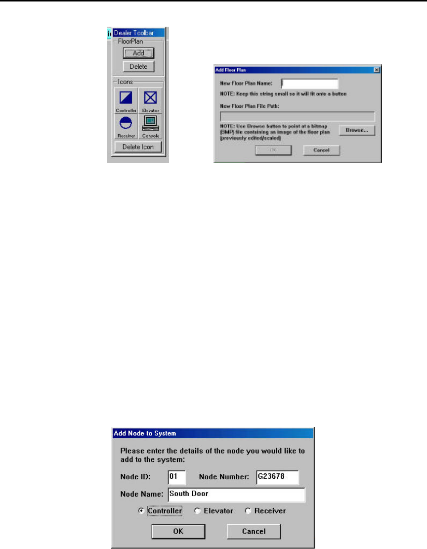
EXI HALO Installation & Operation Manual 981-000003-000
EXI Wireless Systems 43 March 2000
Revision 2.0
Figure 38 - Dealer Toolbar Figure 39 - Floor Plan Entry
In order to add a floor plan, one has to be created in the BMP (Bitmap) format. The maximum allowable
size for a floor plan is 1010 pixels in the horizontal plane, and 660 pixels in the vertical plane. This image
should be stored along with other floor plan images in the directory named “C:\Program
Files\eXI\Halo\floor plans\” which is the default directory for floor plans set up at the factory.
Once a bitmap has been stored in the above location, click on the “Add” button in the Dealer Toolbar. A
panel appears as shown below. Type in the name of the floor, and then click on the “Browse“ button to
locate the floor plan in the default directory described above. The floor plan will be placed under a new
button that has the name of the floor as you had entered.
8.2.3. Adding System Devices
New System Devices such as Controllers, Receivers and Elevator Controllers can be added to the system if
necessary. Remember that all devices in the original installation plan are already added into the application
at the factory, and therefore there should be very little need to add more in the field. This may only become
necessary because of substituting a RIM device, or adding more nodes.
In order to add devices, click on the “Dealer Only” tab and click on “Add”. Fill in the appropriate
information in the “Add Node to System” panel and click on “OK”. Note that the “Node Number” is the
serial number of the RIM associated with the device added.
Figure 40 - Adding a Node to the System
If you try and leave the “Dealer Only” screen after changes are made, a warning pane appears.
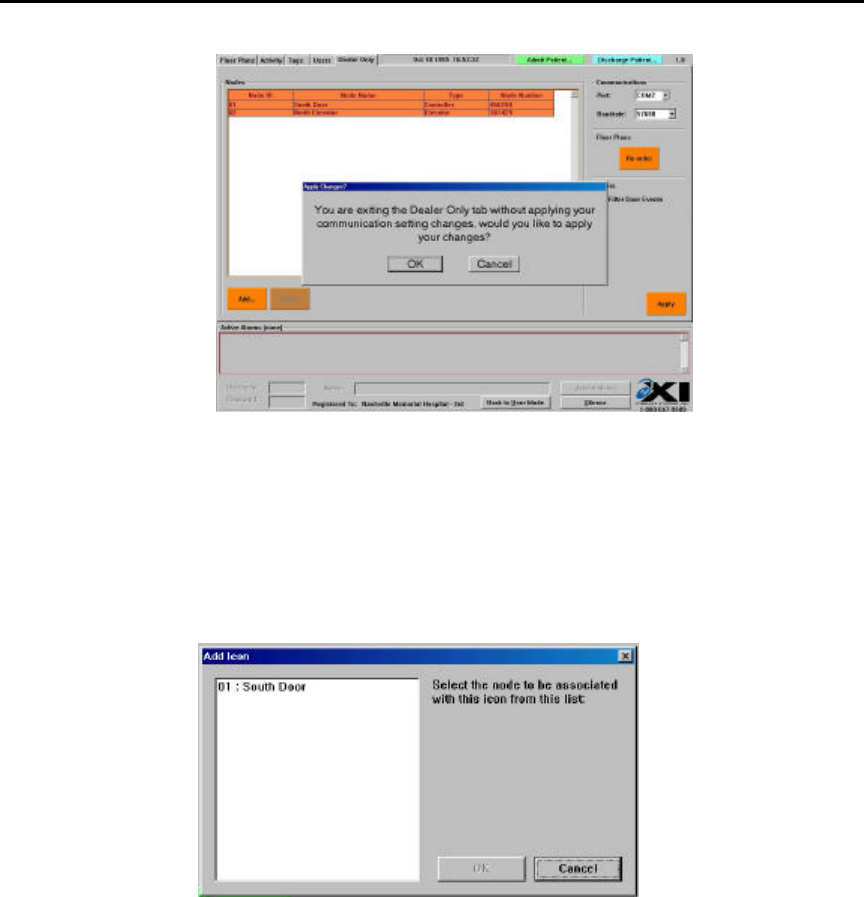
EXI HALO Installation & Operation Manual 981-000003-000
EXI Wireless Systems 44 March 2000
Revision 2.0
Figure 41 - Exit warning from "Dealer Only" Screen
Click on “OK” if you want to accept the changes and then click on the “Floor Plans” tab.
The node that was just entered will need to be placed on the appropriate floor and at the physical location
of the device that the icon represents. Select the appropriate icon from the Dealer Toolbar and drag it to the
correct location on the floor plan. An “Add Icon” panel will show you the list of nodes available for
placement. Highlight the appropriate node and click “OK” to complete the placement.
Figure 42 - Adding Icons for Nodes
8.2.4. Adding Tags and Users
Refer to the “HALO Users Guide” for detailed instructions on how new Tags and Users may be added to
the system.
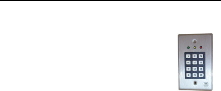
EXI HALO Installation & Operation Manual 981-000003-000
EXI Wireless Systems 45 March 2000
Revision 2.0
9. DKX KEYPAD PROGRAMMING
The Keypad is pre-programmed for the following:
• BYPASS FUNCTION: 1938
• RESET FUNCTION: 1939
To re-Program Keypad:
1) BEGIN programming mode enter: * 382436#
- 3 beeps indicate a valid program code was entered.
2) DELETE all codes enter: *12#
- The code to be deleted must be entered twice. Any outputs assigned to this code do not need to
be entered: Example to delete the code 1938 enter *12 1938#1938#
3) SET code length enter: *19_#
- You may set the code length for 3, 4, 5 or 6 digits. The number entered after *19 dictates the
number of digits in your code.
Example *194# was used to set program for 4 digits.
4) ASSIGN user codes enter: *11_ _ _ _ _ _ # _ #
- The number of codes digits entered depends on the code length selected in the option *19
- The program codes with these selectable outputs.
a) Main Relay Bypass function
b) Aux Relay Reset function
Example 1: *11 1938## was used to set the Main Relay Bypass function so that it
operates when 1938 is entered on the keypad.
Example 2: *11 1939 was used to set the Aux Relay Reset function so that it
operates when 1939 is entered on the keypad.
5) Set the MAIN RELAY BYPASS function time enter: *21_ _#
- Programs the Main Relay Bypass function
Example: *2101# was used to set the main relay bypass function.
6) Set the AUX RELAY RESET function time enter: *22_ _#
- Programs the Aux Relay Reset function
Example: *2201# was used to set the aux relay reset function.
7) EXIT program mode enter: *99#
- EXIT program mode and allows the keypad to return to “on line”

EXI HALO Installation & Operation Manual 981-000003-000
EXI Wireless Systems 46 March 2000
Revision 2.0
10. Appendix A - Weigand Output Specification
Fields # of bits
Even Parity bit (first)1 Parity bit + next 16 bits = 0
Control code 4used to distinguish message types
Door bit 11 = Door open, 0 = Door closed
Maglock bit 11 = Maglock On, 0 = Maglock off
Info - 1 8Info bytes are dependant on message type (see below for descriptions)
Info- 2 8 either bit patterns bit 7 -> bit 0
Info - 3 8 or 6 digits (1 digit = 4 bits)
Odd Parity bit (last)1 Parity bit + previous 16 bits = 1
Total 32
The control code that accompanies Tag serial #’s not only identifies that this message contains a Tag serial #
but it also describes the state of the controller at the time.
Message Types Control Code
Decimal (Binary) Info - 1 Info - 2 Info - 3
Tag Serial # -ABCDEF Tag digits - AB Tag digits - CD Tag digits - EF
- normal 0 (0000) “ “ “
- Bypassed 4 (0100) “ “ “
- TIF alarm 1 (0001) “ “ “
- Loiter 3 (0011) “ “ “
- Host alarm 2 (0010) “ “ “
- Unlock Req 5 (0101) “ “ “
- TIC 7 (0111) “ “ “
- Test Mode 10 (1010) “ “ “
PIN # Entry
0 = no key, A = zero key 8 (1000) eg. 4 Key presses
0 (0000) 0 (0000) “0123”
A(1010) 1(0001) 2(0010)
3(0011)
Event (elevator only) 9 (1001) Door Opened = 00 00 01
Switch Selections 11 (1011) Version # Mode/Option ID Range
High/Low
Status - sent after any
significant changes 12 (1100) Noise Counter Input states Device Status
Status message information definition:
Noise Counter - indicates the number of times the device has detected something on its receiver but couldn’t
make sense of it. This counter decrements over time if noise goes away. The status message gets sent for a
Noise Alarm ON (when this counter rolls over to 100(64Hex)) and then again when the Noise Alarm Clears
(gets back to zero).
Device Status
- Normal (nothing happening) = 00
bit 7 - not used
bit 6 - RF field occupied by tag(s)
bit 5 - In Override
bit 4 - In Unlock
bit 3 - In Bypass
bit 2 - Host alarm
bit 1 - TIC Alarm
bit 0 - TIF alarm
Input states
- nothing “on” will equal 73Hex
bit 7 - not used
bit 6 - Strobe 0 = ignore other host inputs
bit 5 - Override 0 - override request
bit 4 - Unlock 0 = lock release request
bit 3 - bypass key 1 = pressed
bit 2 - Reset key 1 = pressed
bit 1 - Alarm 0 = Host alarm request
bit 0 - Door switch 1 = open, 0 =
closed
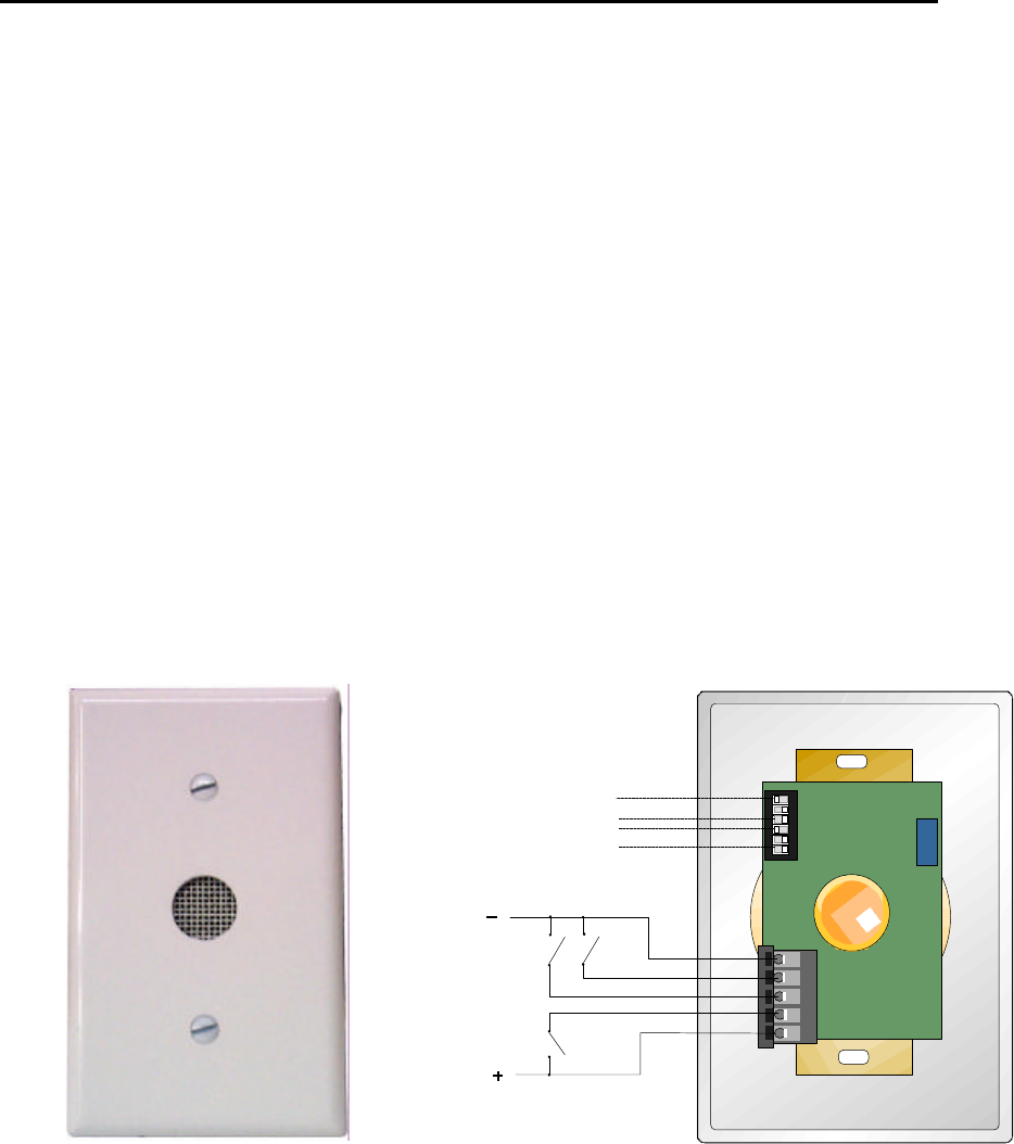
EXI HALO Installation & Operation Manual 981-000003-000
EXI Wireless Systems 47 March 2000
Revision 2.0
Volume
Control
DIP
Switch
[
[
8 Selections for
General Alarm "G"
8 Selections for
Urgent Alarm "U"
( )
General Alarm
Active = Closed
( )
Urgent Alarm
Day-Night Selection
Active = Closed
12 - 24 VDC
Plug-in
Header
Rear
View
Front
View
11. APPENDIX B - ACCESSORIES
11.1. SELECT SOUND MODULE (SSM)
The SSM is an audible annunciator that creates two distinct alarms – a general alarm and an urgent alarm.
The two active tones are programmed from a selection of 8 tones in each group using DIP switches inside
the unit. The SSM has the following additional features:
a) Bakelite plastic cover with ivory finish – flush mounts to standard 1-gang electrical outlet or Wire
mold box for surface mounting.
b) Day/Night loudness control input (12V active high input for reduced night volume by 50% when
active)
c) 16 possible sounds, 8 pleasant tones for general alarms and 8 brisk tones for urgent alarms
d) General and Urgent alarms will alternate if both are activated
e) Field adjustable loudness setting using a volume control (screwdriver required)
f) Reverse polarity protection
g) Operates from 12 to 24 VDC at 0.1A maximum, and is reverse polarity protected.
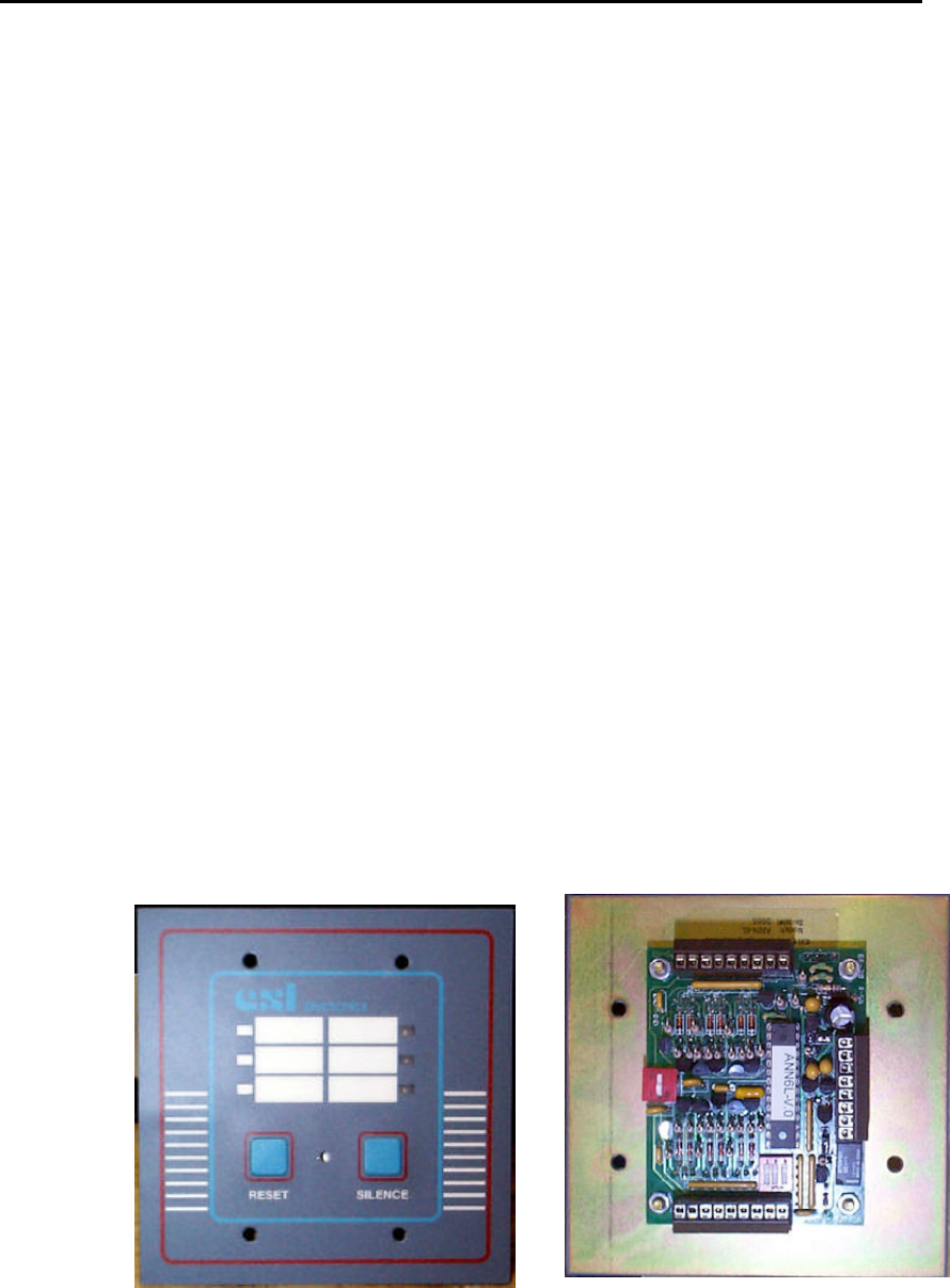
EXI HALO Installation & Operation Manual 981-000003-000
EXI Wireless Systems 48 March 2000
Revision 2.0
11.2. ANN-6L SIX ZONE ANNUNCIATOR
For situations that warrant using the HALO Controller in a stand-alone configuration, without the
Computer Console, the ANN-6L may be used as the annunciator panel. The ANN6L is a six-zone central
alarm panel, usually mounted at the nursing station, reception or a guard station to monitor the status of up
to 6 alarm zones. Each additional ANN-6L will allow six more zones to be monitored. The reset switches
can be ganged so that only one reset switch needs to be pressed to reset all the panels.
Alarms can also be monitored at separate locations with additional ANN-6L panels. These secondary
panels provide either common or local alarm status. Reset can be performed on any ANN-6L when used for
common alarm indication.
• Six Bi color LEDs indicate alarm priority.(red = latching : yellow = non-latching)
• Two distinctive piezo alarms indicate alarm priority. These may be disabled during install.
• Latching and non latching alarms.
• Alarm inputs accepted via N/O or N/C dry contacts or a voltage transition (switch selected
function)
• Reset function can be ganged with other annunciator resets for remote operation
• Silence button deactivates audible alarm, new alarms activate audible alarm
• Onboard Form C relay for auxiliary output.
• Mounts in a standard 2 gang electrical box. (supplied)
• External speaker output provided
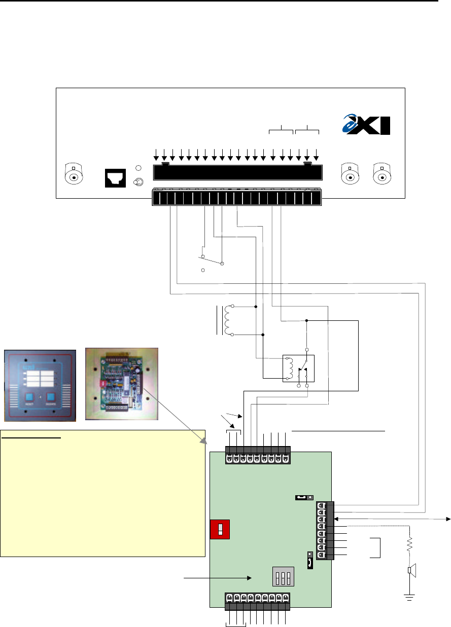
EXI HALO Installation & Operation Manual 981-000003-000
EXI Wireless Systems 49 March 2000
Revision 2.0
12. APPENDIX C - APPLICATION NOTES
12.1. HALO CONTROLLER HOOK UP WITH ANN-6L
RECEIVE
ANTENNA RBC
FCC ID# HE7MAX
TRANSMIT OUTPUT
SEA #1 SEA #2
Made in Canada . . with care Controller
by
Power
1 2 3 4 5 6 7 8 9 10 11 12 13 14 15 16 17 18 19 20
+24V DC Input
System Ground
+12V Ou 200 ma
System Ground
Weigand 0/Data
Weigand 1/Gnd
System Ground
MagOut 24V 200 ma
Door Switch In
System Ground
Unlock In
Override In
Strobe In
N.O
COM
N.C.
N.O
COM
N.C
Relay #1 Relay #2
Alarm In
OFF ON
R2 Controller
Magnetic Contacts located at door
and door frame are closed when door is closed.
(Supplied with HALO Controller Pak)
Magnetic Door Lock,
24 VDC 160 mA Max
ANN-6L
(Front view)
SW2
J2
J1
SW1
P1
P3
P2
24V
12V
OPEN
OFFON
Internal
Beeper
Voltage
Select
C1 = Commons Grounded
Return Inputs high
C2 = Commons Positive
Return Inputs low
12 3
1A
1B
2A
2B
3A
3B
Commons
Power Ground
Common
4B
5A
5B
6A
6B
4A
12/24 VDC
Reset
Beeper
Ground
N.O
N.C.
Common
Relay
Form C SPDT
1A Max @ 24 VDC
82Ω, 2W
External Speaker
(150 mA Max)
SW1 Settings
Sel #1: Open - Alarm Input High active
Closed - Alarm Input Low active
Sel #2: Open - Audible alarm on latched input (A) only
Closed - Audible alarm on both latched and non-latched
Sel #3: Open - Relay activated on latched input (A) only
Closed - Relay activated according to Sel #2 setting
Output low when
Reset button
pressed
24 VDC outboard
relay, 20 mA max
Alarm Inputs 1 to 6 (active when grounded)
A=Latching, Flashing Red light and audible alarm
B=Non-Latching, Flashing Yellow light, no audible alarm
ANN-6L
(Rear view)
Functional Description
Because the door switch function is utilized (Pin 9 of Controller), the door
will be locked by the Controller if it is sensed to be closed when a
transponder enters the field. Data is sent to the HALO Computer, but
Relays #1 and #2 are not activated (Pins 15 to 20). The outboard relay
is energized and input 1B of ANN-6L is grounded so that the ANN-6L
displays a flashing yellow light (1B is a non-latched input).
However, if the door is sensed to be open when a Transponder enters the
field, the alarm will be instant and alarm data will be sent to the Computer,
and both Relays #1 and #2 will be activated for the duration set within
the Controller. Input 1A of the ANN-6L is grounded through Relay #1 of
the Controller, resulting in a flashing red light and audible alarm (if enabled).
As input 1A is a latching input, the ANN-6L requires to be Reset for the
alarm condition to be silenced.
Low Input forces
ANN-6L to Reset
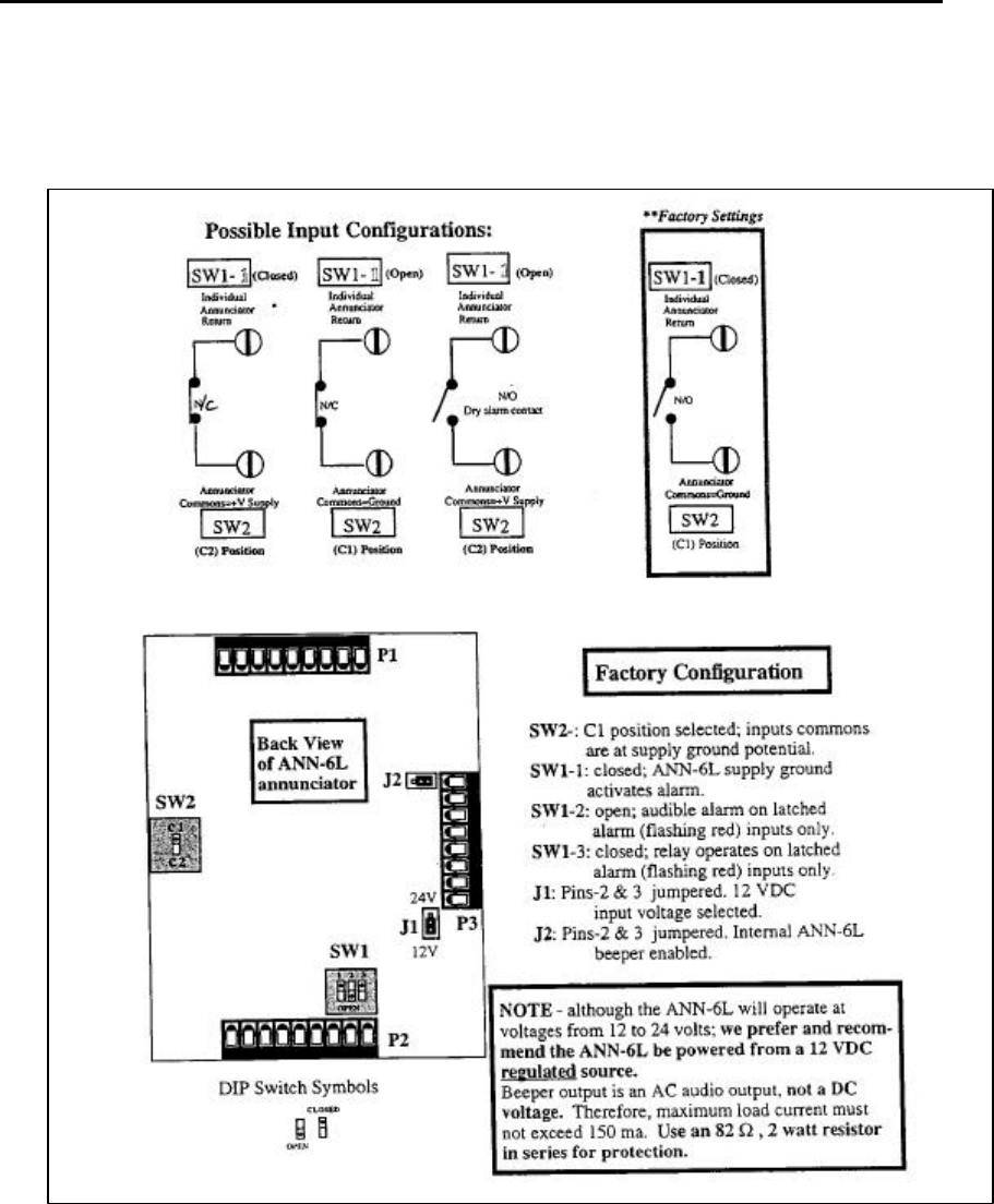
EXI HALO Installation & Operation Manual 981-000003-000
EXI Wireless Systems 50 March 2000
Revision 2.0
12.2. ANN-6L Switch Configurations