Xmark R3R R3 Receiver User Manual Installation and Operations Manual
Xmark Corporation R3 Receiver Installation and Operations Manual
Xmark >
Installation and Operations Manual
© Co
py
ri
g
ht 2001, EXI Wireless S
y
stems Inc. All ri
g
hts reserved.
Installation and Operations Manual
October, 2001
Revision 4.0

EXI HALO Installation & Operation Manual 981-000003-000R4.0
EXI Wireless Systems 2 October 2001
Table of Contents
1. LIMITED WARRANTY...............................................................................................................................................4
2. RECORD OF CHANGES.............................................................................................................................................6
3. FCC REGULATIONS...................................................................................................................................................7
4. INTRODUCTION ........................................................................................ERROR! BOOKMARK NOT DEFINED.
4.1. ABOUT HALO INFANT PROTECTION SYSTEM................................................... ERROR! BOOKMARK NOT DEFINED.
4.2. SYSTEM COMPONENTS .................................................................................... ERROR! BOOKMARK NOT DEFINED.
4.2.1. Door Control Package (Networked) – SR3C01N............................................Error! Bookmark not defined.
4.2.2. HALO Receiver Package (Networked) – SR3R01N.........................................Error! Bookmark not defined.
4.2.3. Elevator Package (Networked) – SR3L01N....................................................Error! Bookmark not defined.
4.2.4. Power Supply...................................................................................................Error! Bookmark not defined.
4.2.5. HALO Console.................................................................................................Error! Bookmark not defined.
4.2.6. eLink Transponder Family..............................................................................Error! Bookmark not defined.
5. INSTALLATION..........................................................................................ERROR! BOOKMARK NOT DEFINED.
5.1. OVERVIEW TO INSTALLING THE HALO SYSTEM............................................. ERROR! BOOKMARK NOT DEFINED.
5.2. SYSTEM WIRING......................................................................................... ERROR! BOOKMARK NOT DEFINED.
5.2.1. Cabling Type ...................................................................................................Error! Bookmark not defined.
5.3. SYSTEM CONNECTION.............................................................................. ERROR! BOOKMARK NOT DEFINED.
5.4. DOOR CONTROL......................................................................................... ERROR! BOOKMARK NOT DEFINED.
5.4.1. LOCATION FOR SRA EXCITER ANTENNAS................................................Error! Bookmark not defined.
5.4.2. LOCATING THE RECEIVER ANTENNA.......................................................Error! Bookmark not defined.
5.4.3. FINALIZE CONTROLLER INSTALLATION ..................................................Error! Bookmark not defined.
5.4.4. MAGLOCK AND DOOR SWITCH INSTALLATION......................................Error! Bookmark not defined.
5.4.5. INDICATORS...................................................................................................Error! Bookmark not defined.
5.4.6. EXCITER ANTENNA MONITOR....................................................................Error! Bookmark not defined.
5.4.7. DOOR SWITCH POLARITY............................................................................Error! Bookmark not defined.
5.4.8. MODE SWITCH SETTING..............................................................................Error! Bookmark not defined.
5.4.9. THRESHOLD / RX SENSITIVITY SWITCH....................................................Error! Bookmark not defined.
5.4.10. R3 CONTROLLER CONFIGURATION SWITCHES......................................Error! Bookmark not defined.
5.4.11. DOOR SWITCH TAMPER...............................................................................Error! Bookmark not defined.
5.4.12. TEST CONTROLLER AND SET UP FIELDS.................................................Error! Bookmark not defined.
5.5. INSTALLING RECEIVERS.......................................................................... ERROR! BOOKMARK NOT DEFINED.
5.5.1. Threshold Switch.............................................................................................Error! Bookmark not defined.
5.6. INSTALLING ELEVATOR CONTROLLERS............................................. ERROR! BOOKMARK NOT DEFINED.
5.6.1. LOCATION FOR SRA-E EXCITER ANTENNAS............................................Error! Bookmark not defined.
5.6.2. Elevator Receive (RX) Antenna.......................................................................Error! Bookmark not defined.
5.6.3. Audible Alarm Module.....................................................................................Error! Bookmark not defined.
5.6.4. Keypad.............................................................................................................Error! Bookmark not defined.
5.6.5. “Door not Closed” Contact ............................................................................Error! Bookmark not defined.
5.6.6. Door Control and Fire Alarm Supervision .....................................................Error! Bookmark not defined.
5.6.7. System Adjustment and Testing .......................................................................Error! Bookmark not defined.
5.7. HALO SYSTEM GROUNDING CONSIDERATIONS................................ ERROR! BOOKMARK NOT DEFINED.
6. PC NETWORKED INSTALLATION.......................................................ERROR! BOOKMARK NOT DEFINED.
7. THEORY OF OPERATION.......................................................................ERROR! BOOKMARK NOT DEFINED.
7.1. TAG COMMUNICATIONS .................................................................................. ERROR! BOOKMARK NOT DEFINED.
7.2. HALO SYSTEM COMMUNICATIONS................................................................ ERROR! BOOKMARK NOT DEFINED.
7.3. HALO CONTROLLER.................................................................................. ERROR! BOOKMARK NOT DEFINED.
7.4. KEYPAD AND PINPAD............................................................................... ERROR! BOOKMARK NOT DEFINED.

EXI HALO Installation & Operation Manual 981-000003-000R4.0
EXI Wireless Systems 3 October 2001
7.5. HALO RECEIVER......................................................................................... ERROR! BOOKMARK NOT DEFINED.
7.6. ELEVATOR CONTROLLER........................................................................ ERROR! BOOKMARK NOT DEFINED.
7.6.1. Pre-Alarm........................................................................................................Error! Bookmark not defined.
7.6.2. Full-Alarm.......................................................................................................Error! Bookmark not defined.
7.6.3. Elevator Bypass...............................................................................................Error! Bookmark not defined.
7.7. CONNECTING TO THE HOST COMPUTER .......................................................... ERROR! BOOKMARK NOT DEFINED.
8. HALO APPLICATION SOFTWARE........................................................ERROR! BOOKMARK NOT DEFINED.
9. KEYPAD PROGRAMMING......................................................................ERROR! BOOKMARK NOT DEFINED.
9.1. DKY KEYPAD............................................................................................... ERROR! BOOKMARK NOT DEFINED.
9.2. PINPAD.......................................................................................................... ERROR! BOOKMARK NOT DEFINED.
9.3. DKX KEYPAD............................................................................................... ERROR! BOOKMARK NOT DEFINED.
10. APPENDIX A - WEIGAND OUTPUT SPECIFICATION..................ERROR! BOOKMARK NOT DEFINED.
11. APPENDIX B - ACCESSORIES.............................................................ERROR! BOOKMARK NOT DEFINED.
11.1. SELECT SOUND MODULE (SSM) ......................................................... ERROR! BOOKMARK NOT DEFINED.
11.2. ANN-6L SIX ZONE ANNUNCIATOR..................................................... ERROR! BOOKMARK NOT DEFINED.
12. APPENDIX C - APPLICATION NOTES..............................................ERROR! BOOKMARK NOT DEFINED.
12.1. HALO CONTROLLER HOOK UP WITH ANN-6L................................ ERROR! BOOKMARK NOT DEFINED.
12.2. ANN-6L SWITCH CONFIGURATIONS........................................................... ERROR! BOOKMARK NOT DEFINED.
13. APPENDIX D............................................................................................ERROR! BOOKMARK NOT DEFINED.
13.1. R2 CONTROLLER CONFIGURATION .................................................. ERROR! BOOKMARK NOT DEFINED.
13.1.1. R2 Door Control Package...............................................................................Error! Bookmark not defined.
13.2. INSTALLING R2 ELEVATOR CONTROLLERS ................................... ERROR! BOOKMARK NOT DEFINED.

EXI HALO Installation & Operation Manual 981-000003-000R4.0
EXI Wireless Systems 4 October 2001
Limited Warranty
1. Warranty: Subject to the limiting conditions set forth below, EXI Wireless Systems Inc. (“EXI”)
hereby warrants that: (a) each product, other than transponders (the “Transponders”), accompanying this
warranty (the “Product”), will be free of defects in materials and workmanship for a period (the
“Product Warranty Period”) of two years after the date of the original sale by EXI of the Product; and
(b) each Transponder accompanying this warranty will be free of defects and workmanship for a period
(the “Transponder Warranty Period”) of, in the case of a WTX-INF/WS Transponder, four years, and in
the case of all other Transponders, three years, after the date of the original sale by EXI of the
Transponder.
2. Notification: If the original or any subsequent purchaser (collectively, the “Purchaser”) of the Product
or Transponder, as the case may be, discovers a defect in materials or workmanship of a Product within
the Product Warranty Period, or a Transponder within the applicable Transponder Warranty Period, the
Purchaser must, within 30 days after the date of such discovery, notify EXI of such defect, and at EXI’s
request, return the defective Product or Transponder, as case the may be, to EXI.
3. Repair or Replacement: Subject to §4, upon acceptance by EXI of responsibility for the defect, EXI
will, in its sole discretion, (a) in the case of a Product, either replace the Product, or provide the
Purchaser with replacement parts for, or repair, the same; and (b) in the case of a Transponder, replace
the Transponder at a discounted price equal to the product of: (i) the nearest whole number of months
remaining in the applicable Transponder Warranty Period; and (ii) the amount of the then monthly
credit available from EXI for the applicable Transponder. EXI’s warranty in respect of any replacement
Product, part thereof, or Transponder, as the case may be, will be for the unexpired portion of the
original warranty period applicable to the relevant Product or Transponder.
4. Exclusion: The warranty referred to in §1 is the sole warranty made by EXI with respect to its Products
and Transponders. EXI makes no other warranty or representation, express or implied, and hereby
disclaims any implied warranty of merchantability or fitness for a particular purpose, statutory or
otherwise, concerning its Products and Transponders. In addition, the warranty will not apply if EXI
has not received a fully completed warranty registration card in respect of the Product or Transponder,
as the case may be, within 30 days after the date of the original purchase from EXI of the same, or the
Product or Transponder, as the case may be, or any part thereof: (a) is damaged by misuse, accident,
negligence, lightning, power surge, brown-out, or leaking, damaged or inoperative batteries, or failure to
maintain the Product or Transponder as specified or required by EXI; (b) is damaged by modifications,
alterations or attachments thereto which are not authorized by EXI; (c) is installed, operated or repaired
contrary to the instructions of EXI; (d) is opened, modified or disassembled in any way without EXI’s
consent; or (d) is used in combination with items, articles or materials not authorized by EXI.
5. Limitation: EXI will only be liable to the Purchaser for direct damages suffered by the Purchaser up to
a maximum amount equal to the total amount of the purchase price actually paid by the Purchaser to
EXI for the Product or Transponder, as the case may be. Specifically, EXI will not be liable for: (a) any
special, indirect or consequential damage, including lost profits, lost revenues, failure to realize
expected savings, or other commercial or economic losses of any kind, even if EXI has been advised of
the possibility of such damage; (b) any loss or damage to any property or for any personal injury or
economic loss or damage caused by the connection of the Product or Transponder, as applicable, to
other devices or systems; (c) any damage or injury arising from or as a result of, misuse, abuse or
incorrect installation, integration or operation of the Product or Transponder, as applicable, by persons
not authorized by EXI; or (d) any defect in any batteries added to or used in conjunction with the
Product or Transponder.
6. Product Limitation: The Purchaser (a) acknowledges that (i) the Products and the Transponders are
not, nor can they be, guaranteed to prevent wandering patients, infant abductions, theft or any other
event for which they were purchased, (ii) the Products and Transponders are only intended to provide
additional safeguards to assist in the prevention of events such as those described in §(i), and (b)
understands fully the foregoing limitations concerning the Products and Transponders, including EXI’s

EXI HALO Installation & Operation Manual 981-000003-000R4.0
EXI Wireless Systems 5 October 2001
limitation on liability described in §5, and agrees to warn, and obtain acknowledgements from, all users
thereof of the same.
7. No Additional Warranties: The terms and conditions herein contain all the warranties and
representations concerning EXI’s Products and Transponders and supersede all previous negotiations,
understandings, communications, representations, warranties and agreements, whether verbal or written,
concerning the Products and Transponders.
8. Deemed Acceptance: The installation or use of the Product or Transponder by or at the direction of the
Purchaser will be deemed as an acceptance by the Purchaser of the terms hereof.
9. Governing Law: The warranty herein will be governed by the domestic laws of the Province of British
Columbia, Canada and the Purchaser hereby attorns to the exclusive jurisdiction of the laws of British
Columbia. The provisions of the United Nations Convention on Contracts for the International Sale of
Goods is hereby excluded.

EXI HALO Installation & Operation Manual 981-000003-000R4.0
EXI Wireless Systems 6 October 2001
1. Record of Changes
October 1999 Combined HALO Installation & Operating Manual and Elevator Manual.
March 2000 Added Cabling types and Threshold / RX Sensitivity Switch Adjust.
March 2001 Changes made to reflect transition from R2 Controller to R3 Controller
October 2001 References to R2 Receiver replaced with R3 Receiver
EXI HALO Installation & Operation Manual 981-000003-000R4.0
EXI Wireless Systems 7 October 2001
2. FCC Regulations
This device complies with Part 15 of the FCC Rules. Operation is subject to the following two
conditions: (1) This device may not cause harmful interference, and (2) This device must accept any
interference received, including interference that may cause undesired operation.
This equipment has been tested and found to comply with the limits for Class B Digital Device,
pursuant to Part 15 of the FCC Rules. These limits are designed to provide reasonable protection
against harmful interference in a residential installation. This equipment generates and can radiate radio
frequency energy and, if not installed and used in accordance with the instructions, may cause harmful
interference to radio communications. However, there is no guarantee that interference will not occur in
a particular installation. If this equipment does cause harmful interference to radio or television
reception, which can be determined by turning the equipment off and on, the user is encouraged to try to
correct the interference by one or more of the following measures.
Reorient or relocate the receiving antenna
Increase the separation between the equipment and receiver
Connect the equipment into an outlet on a circuit different from that to which the receiver is connected
Consult the dealer or an experienced radio/TV technician for help
Any changes or modifications not expressly approved by the party responsible for compliance could
void the user’s authority to operate the equipment.
EXI Wireless Systems Model No.: Halo Infant Tag
CANADA: 287710217261A FCC ID: HE7 PTG
* This device complies with Part 15 of the FCC Rules. Operation is
subject to the following two rules: (1) This device may not cause harmful
interference, and (2) This device must accept any interference received,
including interference that may cause undesired operation.
Made in Canada
EXI Wireless Systems Model No.: Halo Wrist tag
CANADA: TBD FCC ID: HE7 ETG
* This device complies with Part 15 of the FCC Rules. Operation is
subject to the following two rules: (1) This device may not cause harmful
interference, and (2) This device must accept any interference received,
including interference that may cause undesired operation.
Made in Canada
EXI Wireless Systems Model No.: Halo Umbilical tag
CANADA: TBD FCC ID: HE7 FTG
* This device complies with Part 15 of the FCC Rules. Operation is
subject to the following two rules: (1) This device may not cause harmful
interference, and (2) This device must accept any interference received,
including interference that may cause undesired operation.
Made in Canada
EXI HALO Installation & Operation Manual 981-000003-000R4.0
EXI Wireless Systems 8 October 2001
SYSTEM MAINTENANCE SHOULD INCLUDE THE FOLLOWING STEPS:
All Tags should be checked for physical damage after each cleaning, disinfecting or sterilization
procedure.
Each Tag should be tested for correct operation before being attached to an infant. The HALO
software prompts for testing of Tags prior to their deployment. Please refer to the appropriate section
in this manual for the instructions.
The warranty on Tags is 3 years, and the batteries within the Tags are expected to last in excess of the
warranty period depending on the usage pattern. Do not leave Tags in the detection field for long
periods of time, and store them in the foil bags supplied. Failure to do so will result in false alarms,
and will reduce battery life.
Set up a regular system check schedule to verify that the Controllers, Receivers and Tags are
operational. Controllers should have the “Ready” light illuminated to show that they are powered.
Check the operation of the Controller daily by starting a bypass or triggering an alarm using a Tag to
ensure that it is fully operational and protecting the egress point where it is located.
Check each Receiver on a regular basis to ensure that it can receive signals from Tags in the “Off
Body” condition. Failure to regularly check for this operation may lead to failure to detect a Tag that i
s
removed from an infant, and therefore compromising protection for the infant.
Whenever you see an infant who is a patient, look for the Tag on this infant to verify that it is still
securely attached. This may require special knowledge as to the placement of the Tag.
Conduct frequent back
-
ups of Activity Logs for future reference.
The Halo system also supports other eLink based Transponders such as EXI’s Wrist Tag, which may
b
e used for pediatrics or for elderly patients where the Infant Tag’s tamper mechanism is not required,
and Asset Tags which can be used for the protection of high value assets.
EXI Wireless Systems Model No.: Halo Asset tag
CANADA: TBD FCC ID: HE7 ATG
* This device complies with Part 15 of the FCC Rules. Operation is
subject to the following two rules: (1) This device may not cause harmful
interference, and (2) This device must accept any interference received,
including interference that may cause undesired operation.
Made in Canada
Figure 1 -
HALO Receiver Package
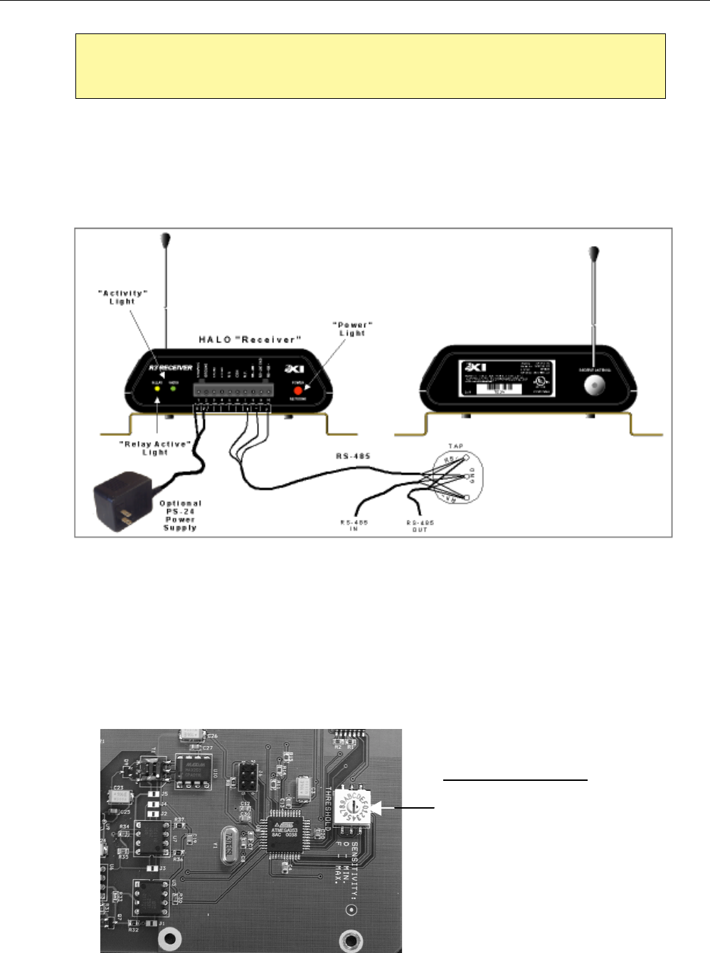
4.5. INSTALLING RECEIVERS
Receivers are meant for use where only a Tag Initiated Communications (TIC) signal needs to be
detected. These TIC signals originate from tags as a result of the tag sensing that it is being tampered
with.
Figure 2 – HALO Receiver Configuration
The “Relay” light on the front of the receiver comes on to indicate relay activation when a “TIC” is
detected. The “Radio” light blinks when there is RF activity sensed on the radio channel. This activity
may be data from tags, or sometimes, intermittent presence of RF noise on the channel. When this
indicator is solid green, there may be a constant high-level RF noise source on the RF channel that
could block tag communications. The “Power” light has two functions, indicating that the Receiver has
been powered up when solid Red, and indicating activity on the RS-485 link when solid Green. This
indicator will alternate between Red and Green in the event the signals sensed on the RS-485
communications are unrecognizable, indicating potential RS-485 line communication trouble.
“Threshold” Switch
“0” = OFF
“F” = MAX sensitivity
Default = “F”
The R3 Controllers have unique serial numbers that are associated with the location that they serve.
Ensure that the correct Controller Serial Number is used at the location being entered on the floor
plan in the computer!
EXI HALO Installation & Operation Manual 981-000003-000R4.0
EXI Wireless Systems 23 October 2001
EXI HALO Installation & Operation Manual 981-000003-000R4.0
EXI Wireless Systems 24 October 2001
Figure 3 – HALO Receiver Settings
4.5.1 THRESHOLD SWITCH
The Threshold switch may be adjusted to increase or reduce the sensitivity of the Receiver and
therefore the range of detection of the Tag. It is also used to reduce or remove some of the
background noise if the Receiver is having trouble detecting tags.
Set the threshold switch at “F” initially, which is the maximum sensitivity setting. Turn the switch
counter-clockwise until the “Radio” light is extinguished, which indicates that the threshold of the
Receiver has been set to overcome any RF ambient noise. The Receiver should be able to detect a
Tag from about a 25’ radius within the protected perimeter at this setting. This detection area is
highly dependent on the layout of the floor, which in turn influences the placement of the Receivers
on that floor.
Generally, ensure that the whole floor has adequate coverage, and eliminate any “null” areas from
which a Tag removal cannot be detected. In the event that the switch setting is required to be below
“A” to overcome noise, it is highly recommended that the noise source be identified and fixed, as a
very low Receiver threshold setting will compromise the tag detection distance, or may even
prevent tag detection altogether.
Receivers have unique serial numbers that are associated with the location that they serve. Ensure
that the correct Receiver is used at the location being entered on the floor plan in the computer!

EXI HALO Installation & Operation Manual 981-000003-000R4.0
EXI Wireless Systems 24 October 2001