Xplore Technologies IX104-112 Tablet PC with GSM and WLAN radios User Manual Aironet Installation for Window
Xplore Technologies Tablet PC with GSM and WLAN radios Aironet Installation for Window
Contents
WLAN Manual

Corporate Headquarters
Cisco Systems, Inc.
170 West Tasman Drive
San Jose, CA 95134-1706
USA
http://www.cisco.com
Tel: 408 526-4000
800 553-NETS (6387)
Fax: 408 526-4100
Cisco Aironet Wireless LAN Client Adapters
Installation and Configuration Guide
for Windows
Customer Order Number:
Text Part Number: OL-1394-06
THE SPECIFICATIONS AND INFORMATION REGARDING THE PRODUCTS IN THIS MANUAL ARE SUBJECT TO CHANGE WITHOUT NOTICE. ALL
STATEMENTS, INFORMATION, AND RECOMMENDATIONS IN THIS MANUAL ARE BELIEVED TO BE ACCURATE BUT ARE PRESENTED WITHOUT
WARRANTY OF ANY KIND, EXPRESS OR IMPLIED. USERS MUST TAKE FULL RESPONSIBILITY FOR THEIR APPLICATION OF ANY PRODUCTS.
THE SOFTWARE LICENSE AND LIMITED WARRANTY FOR THE ACCOMPANYING PRODUCT ARE SET FORTH IN THE INFORMATION PACKET THAT
SHIPPED WITH THE PRODUCT AND ARE INCORPORATED HEREIN BY THIS REFERENCE. IF YOU ARE UNABLE TO LOCATE THE SOFTWARE LICENSE
OR LIMITED WARRANTY, CONTACT YOUR CISCO REPRESENTATIVE FOR A COPY.
The following information is for FCC compliance of Class A devices: This equipment has been tested and found to comply with the limits for a Class A digital device, pursuant
to part 15 of the FCC rules. These limits are designed to provide reasonable protection against harmful interference when the equipment is operated in a commercial
environment. This equipment generates, uses, and can radiate radio-frequency energy and, if not installed and used in accordance with the instruction manual, may cause
harmful interference to radio communications. Operation of this equipment in a residential area is likely to cause harmful interference, in which case users will be required
to correct the interference at their own expense.
The following information is for FCC compliance of Class B devices: The equipment described in this manual generates and may radiate radio-frequency energy. If it is not
installed in accordance with Cisco’s installation instructions, it may cause interference with radio and television reception. This equipment has been tested and found to
comply with the limits for a Class B digital device in accordance with the specifications in part 15 of the FCC rules. These specifications are designed to provide reasonable
protection against such interference in a residential installation. However, there is no guarantee that interference will not occur in a particular installation.
Modifying the equipment without Cisco’s written authorization may result in the equipment no longer complying with FCC requirements for Class A or Class B digital
devices. In that event, your right to use the equipment may be limited by FCC regulations, and you may be required to correct any interference to radio or television
communications at your own expense.
You can determine whether your equipment is causing interference by turning it off. If the interference stops, it was probably caused by the Cisco equipment or one of its
peripheral devices. If the equipment causes interference to radio or television reception, try to correct the interference by using one or more of the following measures:
• Turn the television or radio antenna until the interference stops.
• Move the equipment to one side or the other of the television or radio.
• Move the equipment farther away from the television or radio.
• Plug the equipment into an outlet that is on a different circuit from the television or radio. (That is, make certain the equipment and the television or radio are on circuits
controlled by different circuit breakers or fuses.)
Modifications to this product not authorized by Cisco Systems, Inc. could void the FCC approval and negate your authority to operate the product.
The Cisco implementation of TCP header compression is an adaptation of a program developed by the University of California, Berkeley (UCB) as part of UCB’s public
domain version of the UNIX operating system. All rights reserved. Copyright © 1981, Regents of the University of California.
NOTWITHSTANDING ANY OTHER WARRANTY HEREIN, ALL DOCUMENT FILES AND SOFTWARE OF THESE SUPPLIERS ARE PROVIDED “AS IS” WITH
ALL FAULTS. CISCO AND THE ABOVE-NAMED SUPPLIERS DISCLAIM ALL WARRANTIES, EXPRESSED OR IMPLIED, INCLUDING, WITHOUT
LIMITATION, THOSE OF MERCHANTABILITY, FITNESS FOR A PARTICULAR PURPOSE AND NONINFRINGEMENT OR ARISING FROM A COURSE OF
DEALING, USAGE, OR TRADE PRACTICE.
IN NO EVENT SHALL CISCO OR ITS SUPPLIERS BE LIABLE FOR ANY INDIRECT, SPECIAL, CONSEQUENTIAL, OR INCIDENTAL DAMAGES, INCLUDING,
WITHOUT LIMITATION, LOST PROFITS OR LOSS OR DAMAGE TO DATA ARISING OUT OF THE USE OR INABILITY TO USE THIS MANUAL, EVEN IF CISCO
OR ITS SUPPLIERS HAVE BEEN ADVISED OF THE POSSIBILITY OF SUCH DAMAGES.
CCIP, CCSP, the Cisco Arrow logo, the Cisco Powered Network mark, Cisco Unity, Follow Me Browsing, FormShare, and StackWise are trademarks of Cisco Systems, Inc.;
Changing the Way We Work, Live, Play, and Learn, and iQuick Study are service marks of Cisco Systems, Inc.; and Aironet, ASIST, BPX, Catalyst, CCDA, CCDP, CCIE,
CCNA, CCNP, Cisco, the Cisco Certified Internetwork Expert logo, Cisco IOS, the Cisco IOS logo, Cisco Press, Cisco Systems, Cisco Systems Capital, the Cisco Systems
logo, Empowering the Internet Generation, Enterprise/Solver, EtherChannel, EtherSwitch, Fast Step, GigaStack, Internet Quotient, IOS, IP/TV, iQ Expertise, the iQ logo, iQ
Net Readiness Scorecard, LightStream, MGX, MICA, the Networkers logo, Networking Academy, Network Registrar, Packet, PIX, Post-Routing, Pre-Routing, RateMUX,
Registrar, ScriptShare, SlideCast, SMARTnet, StrataView Plus, Stratm, SwitchProbe, TeleRouter, The Fastest Way to Increase Your Internet Quotient, TransPath, and VCO
are registered trademarks of Cisco Systems, Inc. and/or its affiliates in the U.S. and certain other countries.
All other trademarks mentioned in this document or Web site are the property of their respective owners. The use of the word partner does not imply a partnership relationship
between Cisco and any other company. (0304R)
Cisco Aironet Wireless LAN Client Adapters Installation and Configuration Guide for Windows
Copyright © 2001-2003 Cisco Systems, Inc.
All rights reserved.

iii
Cisco Aironet Wireless LAN Client Adapters Installation and Configuration Guide for Windows
OL-1394-06
CONTENTS
Preface xi
Audience xii
Purpose xii
Organization xii
Conventions xiii
Related Publications xv
Obtaining Documentation xv
Cisco.com xv
Documentation CD-ROM xv
Ordering Documentation xvi
Documentation Feedback xvi
Obtaining Technical Assistance xvi
Cisco.com xvi
Technical Assistance Center xvii
Cisco TAC Website xvii
Cisco TAC Escalation Center xviii
Obtaining Additional Publications and Information xviii
Product Overview 1-1
Introduction to the Client Adapters 1-2
Terminology 1-3
Hardware Components 1-3
Radio 1-3
Radio Antenna 1-4
LEDs 1-4
Software Components 1-5
Radio Firmware 1-5
Driver 1-5
Client Utilities 1-6
Overview of ACU 1-6
Buttons on the ACU Screens 1-8

Contents
iv
Cisco Aironet Wireless LAN Client Adapters Installation and Configuration Guide for Windows OL-1394-06
Network Configurations Using Client Adapters 1-8
Ad Hoc Wireless LAN 1-9
Wireless Infrastructure with Workstations Accessing a Wired LAN 1-10
Preparing for Installation 2-1
Safety information 2-2
FCC Safety Compliance Statement 2-2
Safety Guidelines 2-2
Warnings 2-3
Unpacking the Client Adapter 2-3
Package Contents 2-3
System Requirements 2-4
Site Requirements 2-5
For Infrastructure Devices 2-5
For Client Devices 2-6
Installing the Client Adapter 3-1
Installing or Upgrading the Client Adapter Software 3-2
Installing or Upgrading the Client Adapter Software on Windows 98, 98 SE, 2000, Me, or XP 3-2
Installing or Upgrading the Client Adapter Software on Windows NT 3-12
Verifying Installation 3-22
Deciding How to Configure Your Client Adapter (Windows XP Only) 3-22
Selecting Among Several Installed Client Adapters 3-24
Using the Profile Manager 4-1
Overview of Profile Manager 4-2
Opening Profile Manager 4-2
Creating a New Profile 4-3
Including a Profile in Auto Profile Selection 4-4
Selecting the Active Profile 4-6
Modifying a Profile 4-7
Editing a Profile 4-7
Setting a Profile to Default Values 4-8
Renaming a Profile 4-8
Deleting a Profile 4-8
Importing and Exporting Profiles 4-9
Importing a Profile 4-9
Exporting a Profile 4-9
Granting or Denying Access to Non-Administrative Users 4-10

Contents
v
Cisco Aironet Wireless LAN Client Adapters Installation and Configuration Guide for Windows
OL-1394-06
Configuring the Client Adapter 5-1
Overview 5-2
Setting System Parameters 5-3
Setting RF Network Parameters 5-7
Setting Advanced Infrastructure Parameters 5-14
Setting Advanced Ad Hoc Parameters 5-17
Setting Network Security Parameters 5-20
Setting the Allow Association to Mixed Cells Parameter 5-21
Overview of Security Features 5-21
Static WEP Keys 5-22
EAP (with Dynamic WEP Keys) 5-22
Additional WEP Key Security Features 5-25
Reporting Access Points that Fail LEAP Authentication 5-26
Fast Secure Roaming 5-26
Synchronizing Security Features 5-27
Using Static WEP 5-29
Entering a New Static WEP Key 5-29
Overwriting an Existing Static WEP Key 5-30
Disabling Static WEP 5-31
Enabling LEAP 5-31
Enabling Host-Based EAP 5-34
Enabling EAP-TLS 5-36
Enabling PEAP 5-39
Enabling EAP-SIM 5-41
Disabling LEAP or Host-Based EAP 5-42
Disabling LEAP 5-42
Disabling Host-Based EAP 5-42
Using EAP Authentication 6-1
Overview 6-2
Using LEAP 6-2
Using LEAP with the Windows Username and Password 6-3
After Profile Selection or Card Insertion 6-3
After a Reboot or Logon 6-4
After Your LEAP Credentials Expire 6-5
Using LEAP with an Automatically Prompted Login 6-6
After Profile Selection or Card Insertion 6-6
After a Reboot or Logon 6-7
After Your LEAP Credentials Expire 6-9

Contents
vi
Cisco Aironet Wireless LAN Client Adapters Installation and Configuration Guide for Windows OL-1394-06
Using LEAP with a Manually Prompted Login 6-9
After Profile Selection 6-9
After a Reboot, Logon, or Card Insertion 6-11
After Your LEAP Credentials Expire 6-13
Using LEAP with a Saved Username and Password 6-13
After Profile Selection or Card Insertion 6-13
After a Reboot or Logon 6-14
After Your LEAP Credentials Expire 6-14
Using EAP-TLS 6-15
After Profile Selection or Card Insertion 6-15
After a Reboot or Logon 6-15
Using PEAP 6-16
After Profile Selection, Card Insertion, Reboot, or Logon 6-16
Windows NT or 2000 Domain Databases or LDAP Databases Only 6-16
OTP Databases Only 6-17
After Your Password Expires (Windows NT or 2000 Domain Databases Only) 6-18
After Your PIN Expires (OTP Databases Only) 6-19
Using EAP-SIM 6-19
If You Are Prompted for the PIN 6-20
If the PIN Is Stored on the Computer 6-21
Restarting the Authentication Process 6-21
Performing Diagnostics 7-1
Overview of ACU Diagnostic Tools 7-2
Setting Parameters that Affect ACU Diagnostic Tools 7-3
Viewing the Current Status of Your Client Adapter 7-4
Viewing Statistics for Your Client Adapter 7-11
Viewing the Link Status Meter 7-16
Running an RF Link Test 7-17
Using the Aironet Client Monitor (ACM) 8-1
Overview of ACM 8-2
The ACM Icon 8-2
Tool Tip Window 8-3
Pop-Up Menu 8-5
About 8-5
Exit 8-6
Launch Aironet Client Utility 8-6
Troubleshooting 8-6

Contents
vii
Cisco Aironet Wireless LAN Client Adapters Installation and Configuration Guide for Windows
OL-1394-06
Preferences 8-6
Turn Radio On/Off 8-7
Reauthenticate 8-8
Select Profile 8-8
Show Connection Status 8-9
Routine Procedures 9-1
Inserting and Removing a Client Adapter 9-2
Inserting a Client Adapter 9-2
Inserting a PC Card or PC-Cardbus Card 9-2
Inserting a PCI Card 9-3
Removing a Client Adapter 9-4
Removing a PC Card or PC-Cardbus Card 9-4
Removing a PCI Card 9-5
Client Adapter Software Procedures 9-5
Finding the Install Wizard Version 9-5
Upgrading the Client Adapter Software 9-6
Uninstalling the Client Adapter Software 9-6
Finding the Driver Version 9-7
Firmware Procedures 9-8
Finding the Firmware Version 9-8
Upgrading the Firmware 9-8
Preventing the Driver from Upgrading the Firmware 9-10
ACU Procedures 9-12
Opening ACU 9-12
Exiting ACU 9-13
Modifying ACU Installation Settings 9-13
Finding the Version of ACU 9-13
Adding the ACU Icon to or Removing it from the Desktop 9-14
Accessing Online Help 9-14
ACM Procedures 9-15
Restarting the Client Adapter 9-15
Turning Your Client Adapter’s Radio On or Off 9-15
Uninstalling the Microsoft Hot Fix 9-16

Contents
viii
Cisco Aironet Wireless LAN Client Adapters Installation and Configuration Guide for Windows OL-1394-06
Troubleshooting 10-1
Accessing the Latest Troubleshooting Information 10-2
Interpreting the Indicator LEDs 10-2
Troubleshooting the Client Adapter 10-3
Using the Troubleshooting Utility 10-4
Diagnosing Your Client Adapter’s Operation 10-4
Saving the Detailed Report to a Text File 10-6
Accessing Online Help 10-7
Client Adapter Recognition Problems 10-7
Resolving Resource Conflicts 10-8
Resolving Resource Conflicts in Windows 98, 98 SE, and Me 10-8
Resolving Resource Conflicts in Windows NT 10-9
Resolving Resource Conflicts in Windows 2000 10-9
Resolving Resource Conflicts in Windows XP 10-10
Problems Associating to an Access Point 10-11
Problems Authenticating to an Access Point 10-11
Problems Connecting to the Network 10-11
Prioritizing Network Connections (Windows 2000 and XP Only) 10-11
Losing Association upon Resuming from Suspend Mode
(Windows NT and Mini PCI Cards Only) 10-12
Parameters Missing from Profile Manager Screen 10-12
Windows Wireless Network Connection Icon Shows Unavailable Connection (Windows XP
Only) 10-12
LEAP Login Screen Does Not Appear Before Windows Login Screen (Windows 98, 98 SE, and Me
Only) 10-13
Microsoft Hot Fix (Windows 98 and 98 SE Only) 10-13
Error Messages 10-13
General Error Messages 10-14
LEAP Authentication Error Messages 10-18
PEAP Authentication Error Messages 10-21
For All PEAP-Supported Databases 10-21
For Windows NT or 2000 Domain Databases 10-22
For All OTP Databases 10-23
For OTP Databases Using Secure Computing SofToken Version 1.3 10-24
For OTP Databases Using Secure Computing SofToken II Version 2.0 10-25
For OTP Databases Using RSA SecurID Version 2.5 10-26
EAP-SIM Authentication Error Messages 10-26

Contents
ix
Cisco Aironet Wireless LAN Client Adapters Installation and Configuration Guide for Windows
OL-1394-06
Technical Specifications A-1
Translated Safety Warnings B-1
Explosive Device Proximity Warning B-2
Dipole Antenna Installation Warning B-3
Warning for Laptop Users B-4
Declarations of Conformity and Regulatory Information C-1
Manufacturer’s Federal Communication Commission Declaration of Conformity Statement C-2
Department of Communications – Canada C-3
Canadian Compliance Statement C-3
European Community, Switzerland, Norway, Iceland, and Liechtenstein C-4
Declaration of Conformity with Regard to the R&TTE Directive 1999/5/EC C-4
2.4-GHz Client Adapters C-5
5-GHz Client Adapters C-6
Declaration of Conformity for RF Exposure C-6
Guidelines for Operating Cisco Aironet Wireless LAN Client Adapters in Japan C-6
Japanese Translation C-6
English Translation C-7
Channels, Power Levels, and Antenna Gains D-1
Channels D-2
IEEE 802.11a D-2
IEEE 802.11b D-3
Maximum Power Levels and Antenna Gains D-4
IEEE 802.11a D-4
IEEE 802.11b D-4
Configuring the Client Adapter through Windows XP E-1
Overview E-2
Overview of Security Features E-2
Static WEP Keys E-2
EAP (with Dynamic WEP Keys) E-2
Configuring the Client Adapter E-4
Enabling EAP-TLS Authentication E-8
Enabling PEAP Authentication E-10
Enabling EAP-SIM Authentication E-14
Associating to an Access Point Using Windows XP E-16
Viewing the Current Status of Your Client Adapter E-17

Contents
x
Cisco Aironet Wireless LAN Client Adapters Installation and Configuration Guide for Windows OL-1394-06
Performing a Site Survey F-1
Overview F-2
Guidelines F-2
Additional Information F-2
Specifying Signal Strength Units F-3
Using Passive Mode F-3
Using Active Mode F-7
Forcing the Client Adapter to Reassociate F-13
G
LOSSARY
I
NDEX

xi
Cisco Aironet Wireless LAN Client Adapters Installation and Configuration Guide for Windows
OL-1394-06
Preface
The preface provides an overview of the Cisco Aironet Wireless LAN Client Adapters Installation and
Configuration Guide for Windows, references related publications, and explains how to obtain other
documentation and technical assistance, if necessary.
The following topics are covered in this section:
•Audience, page xii
•Purpose, page xii
•Organization, page xii
•Conventions, page xiii
•Related Publications, page xv
•Obtaining Documentation, page xv
•Obtaining Technical Assistance, page xvi
•Obtaining Additional Publications and Information, page xviii

xii
Cisco Aironet Wireless LAN Client Adapters Installation and Configuration Guide for Windows OL-1394-06
Preface
Audience
Audience
This publication is for the person responsible for installing, configuring, and maintaining a Cisco
Aironet Wireless LAN Client Adapter on a computer running Microsoft Windows 98, 98 SE, NT, 2000,
Me, or XP. This person should be familiar with computing devices and with network terms and concepts.
Purpose
This publication describes the Cisco Aironet client adapters and explains how to install, configure, and
troubleshoot them.
Note This version of the Cisco Aironet Wireless LAN Client Adapters Installation and Configuration Guide
for Windows pertains specifically to versions of the client adapter software that are installed through an
Install Wizard file. If you are using, installing, or upgrading to versions of client adapter software that
do not use the Install Wizard, refer to version OL-1394-04 of this manual for information and
instructions.
Organization
This publication contains the following chapters:
•Chapter 1, “Product Overview,” describes the client adapters and their hardware and software
components and illustrates two common network configurations.
•Chapter 2, “Preparing for Installation,” provides information that you need to know before installing
a client adapter, such as safety information and system requirements.
•Chapter 3, “Installing the Client Adapter,” provides instructions for installing client adapter
software.
•Chapter 4, “Using the Profile Manager,” explains how to use the ACU profile manager feature to
create and manage profiles for your client adapter.
•Chapter 5, “Configuring the Client Adapter,” explains how to change the configuration parameters
for a specific profile.
•Chapter 6, “Using EAP Authentication,” explains the sequence of events that occurs and the actions
you must take when a profile that is set for EAP authentication is selected for use.
•Chapter 7, “Performing Diagnostics,” explains how to use ACU to perform user-level diagnostics.
•Chapter 8, “Using the Aironet Client Monitor (ACM),” explains how to use the Aironet Client
Monitor (ACM) to access status information about your client adapter and perform basic tasks.
•Chapter 9, “Routine Procedures,” provides procedures for common tasks related to the client
adapters, such as uninstalling client adapter software and restarting an adapter.
•Chapter 10, “Troubleshooting,” provides information for diagnosing and correcting common
problems that may be encountered when installing or operating a client adapter.
•Appendix A, “Technical Specifications,” lists the physical, radio, power, and regulatory
specifications for the client adapters.
•Appendix B, “Translated Safety Warnings,” provides translations of client adapter safety warnings
in nine languages.

xiii
Cisco Aironet Wireless LAN Client Adapters Installation and Configuration Guide for Windows
OL-1394-06
Preface Conventions
•Appendix C, “Declarations of Conformity and Regulatory Information,” provides declarations of
conformity and regulatory information for the client adapters.
•Appendix D, “Channels, Power Levels, and Antenna Gains,” lists the IEEE 802.11a and IEEE
802.11b channels supported by the world's regulatory domains as well as the maximum power levels
and antenna gains allowed per domain.
•Appendix E, “Configuring the Client Adapter through Windows XP,” explains how to configure and
use your client adapter with Windows XP.
•Appendix F, “Performing a Site Survey,” shows people who are responsible for conducting a site
survey how they can use ACU to determine the best placement for infrastructure devices within a
wireless network.
Conventions
This publication uses the following conventions to convey instructions and information:
•Commands and keywords are in boldface.
•Variables are in italics.
•Configuration parameters are capitalized.
•Notes, cautions, and warnings use the following conventions and symbols:
Note Means reader take note. Notes contain helpful suggestions or references to materials not contained in
this manual.
Caution Means reader be careful. In this situation, you might do something that could result in equipment
damage or loss of data.
Warning
This warning symbol means danger. You are in a situation that could cause bodily injury. Before you
work on any equipment, be aware of the hazards involved with electrical circuitry and be familiar
with standard practices for preventing accidents. (To see translations of the warnings that appear
in this publication, refer to the appendix “Translated Safety Warnings.”)
Waarschuwing
Dit waarschuwingssymbool betekent gevaar. U verkeert in een situatie die lichamelijk letsel kan
veroorzaken. Voordat u aan enige apparatuur gaat werken, dient u zich bewust te zijn van de bij
elektrische schakelingen betrokken risico’s en dient u op de hoogte te zijn van standaard
maatregelen om ongelukken te voorkomen. (Voor vertalingen van de waarschuwingen die in deze
publicatie verschijnen, kunt u het aanhangsel “Translated Safety Warnings” (Vertalingen van
veiligheidsvoorschriften) raadplegen.)
Varoitus
Tämä varoitusmerkki merkitsee vaaraa. Olet tilanteessa, joka voi johtaa ruumiinvammaan. Ennen
kuin työskentelet minkään laitteiston parissa, ota selvää sähkökytkentöihin liittyvistä vaaroista ja
tavanomaisista onnettomuuksien ehkäisykeinoista. (Tässä julkaisussa esiintyvien varoitusten
käännökset löydät liitteestä "Translated Safety Warnings" (käännetyt turvallisuutta koskevat
varoitukset).)

xiv
Cisco Aironet Wireless LAN Client Adapters Installation and Configuration Guide for Windows OL-1394-06
Preface
Conventions
Attention
Ce symbole d’avertissement indique un danger. Vous vous trouvez dans une situation pouvant
entraîner des blessures. Avant d’accéder à cet équipement, soyez conscient des dangers posés par
les circuits électriques et familiarisez-vous avec les procédures courantes de prévention des
accidents. Pour obtenir les traductions des mises en garde figurant dans cette publication, veuillez
consulter l’annexe intitulée « Translated Safety Warnings » (Traduction des avis de sécurité).
Warnung
Dieses Warnsymbol bedeutet Gefahr. Sie befinden sich in einer Situation, die zu einer
Körperverletzung führen könnte. Bevor Sie mit der Arbeit an irgendeinem Gerät beginnen, seien Sie
sich der mit elektrischen Stromkreisen verbundenen Gefahren und der Standardpraktiken zur
Vermeidung von Unfällen bewußt. (Übersetzungen der in dieser Veröffentlichung enthaltenen
Warnhinweise finden Sie im Anhang mit dem Titel “Translated Safety Warnings” (Übersetzung der
Warnhinweise).)
Avvertenza
Questo simbolo di avvertenza indica un pericolo. Si è in una situazione che può causare infortuni.
Prima di lavorare su qualsiasi apparecchiatura, occorre conoscere i pericoli relativi ai circuiti
elettrici ed essere al corrente delle pratiche standard per la prevenzione di incidenti. La traduzione
delle avvertenze riportate in questa pubblicazione si trova nell’appendice, “Translated Safety
Warnings” (Traduzione delle avvertenze di sicurezza).
Advarsel
Dette varselsymbolet betyr fare. Du befinner deg i en situasjon som kan føre til personskade. Før du
utfører arbeid på utstyr, må du være oppmerksom på de faremomentene som elektriske kretser
innebærer, samt gjøre deg kjent med vanlig praksis når det gjelder å unngå ulykker. (Hvis du vil se
oversettelser av de advarslene som finnes i denne publikasjonen, kan du se i vedlegget "Translated
Safety Warnings" [Oversatte sikkerhetsadvarsler].)
Aviso
Este símbolo de aviso indica perigo. Encontra-se numa situação que lhe poderá causar danos fisicos.
Antes de começar a trabalhar com qualquer equipamento, familiarize-se com os perigos
relacionados com circuitos eléctricos, e com quaisquer práticas comuns que possam prevenir
possíveis acidentes. (Para ver as traduções dos avisos que constam desta publicação, consulte o
apêndice “Translated Safety Warnings” - “Traduções dos Avisos de Segurança”).
¡Advertencia!
Este símbolo de aviso significa peligro. Existe riesgo para su integridad física. Antes de manipular
cualquier equipo, considerar los riesgos que entraña la corriente eléctrica y familiarizarse con los
procedimientos estándar de prevención de accidentes. (Para ver traducciones de las advertencias
que aparecen en esta publicación, consultar el apéndice titulado “Translated Safety Warnings.”)
Varning!
Denna varningssymbol signalerar fara. Du befinner dig i en situation som kan leda till personskada.
Innan du utför arbete på någon utrustning måste du vara medveten om farorna med elkretsar och
känna till vanligt förfarande för att förebygga skador. (Se förklaringar av de varningar som
förekommer i denna publikation i appendix "Translated Safety Warnings" [Översatta
säkerhetsvarningar].)

xv
Cisco Aironet Wireless LAN Client Adapters Installation and Configuration Guide for Windows
OL-1394-06
Preface Related Publications
Related Publications
For more information about Cisco Aironet Wireless LAN Client Adapters for Windows, refer to the
following publications:
•Release Notes for Cisco Aironet Client Adapter Install Wizard
•Release Notes for Cisco Aironet Client Adapter Firmware
For more information about related Cisco Aironet products, refer to the publications for your
infrastructure device. You can access Cisco Aironet technical documentation at this URL:
http://www.cisco.com/en/US/products/hw/wireless/index.html
Obtaining Documentation
Cisco provides several ways to obtain documentation, technical assistance, and other technical
resources. These sections explain how to obtain technical information from Cisco Systems.
Cisco.com
You can access the most current Cisco documentation on the World Wide Web at this URL:
http://www.cisco.com/univercd/home/home.htm
You can access the Cisco website at this URL:
http://www.cisco.com
International Cisco websites can be accessed from this URL:
http://www.cisco.com/public/countries_languages.shtml
Documentation CD-ROM
Cisco documentation and additional literature are available in a Cisco Documentation CD-ROM
package, which may have shipped with your product. The Documentation CD-ROM is updated regularly
and may be more current than printed documentation. The CD-ROM package is available as a single unit
or through an annual or quarterly subscription.
Registered Cisco.com users can order a single Documentation CD-ROM (product number
DOC-CONDOCCD=) through the Cisco Ordering tool:
http://www.cisco.com/en/US/partner/ordering/ordering_place_order_ordering_tool_launch.html
All users can order monthly or quarterly subscriptions through the online Subscription Store:
http://www.cisco.com/go/subscription

xvi
Cisco Aironet Wireless LAN Client Adapters Installation and Configuration Guide for Windows OL-1394-06
Preface
Obtaining Technical Assistance
Ordering Documentation
You can find instructions for ordering documentation at this URL:
http://www.cisco.com/univercd/cc/td/doc/es_inpck/pdi.htm
You can order Cisco documentation in these ways:
•Registered Cisco.com users (Cisco direct customers) can order Cisco product documentation from
the Networking Products MarketPlace:
http://www.cisco.com/en/US/partner/ordering/index.shtml
•Nonregistered Cisco.com users can order documentation through a local account representative by
calling Cisco Systems Corporate Headquarters (California, U.S.A.) at 408 526-7208 or, elsewhere
in North America, by calling 800 553-NETS (6387).
Documentation Feedback
You can submit comments electronically on Cisco.com. On the Cisco Documentation home page, click
Feedback at the top of the page.
You can e-mail your comments to bug-doc@cisco.com.
You can submit comments by using the response card (if present) behind the front cover of your
document or by writing to the following address:
Cisco Systems
Attn: Customer Document Ordering
170 West Tasman Drive
San Jose, CA 95134-9883
We appreciate your comments.
Obtaining Technical Assistance
Cisco provides Cisco.com, which includes the Cisco Technical Assistance Center (TAC) website, as a
starting point for all technical assistance. Customers and partners can obtain online documentation,
troubleshooting tips, and sample configurations from the Cisco TAC website. Cisco.com registered users
have complete access to the technical support resources on the Cisco TAC website, including TAC tools
and utilities.
Cisco.com
Cisco.com offers a suite of interactive, networked services that let you access Cisco information,
networking solutions, services, programs, and resources at any time, from anywhere in the world.
Cisco.com provides a broad range of features and services to help you with these tasks:
•Streamline business processes and improve productivity
•Resolve technical issues with online support
•Download and test software packages

xvii
Cisco Aironet Wireless LAN Client Adapters Installation and Configuration Guide for Windows
OL-1394-06
Preface Obtaining Technical Assistance
•Order Cisco learning materials and merchandise
•Register for online skill assessment, training, and certification programs
To obtain customized information and service, you can self-register on Cisco.com at this URL:
http://tools.cisco.com/RPF/register/register.do
Technical Assistance Center
The Cisco TAC is available to all customers who need technical assistance with a Cisco product,
technology, or solution. Two types of support are available: the Cisco TAC website and the Cisco TAC
Escalation Center. The type of support that you choose depends on the priority of the problem and the
conditions stated in service contracts, when applicable.
We categorize Cisco TAC inquiries according to urgency:
•Priority level 4 (P4)—You need information or assistance concerning Cisco product capabilities,
product installation, or basic product configuration. There is little or no impact to your business
operations.
•Priority level 3 (P3)—Operational performance of the network is impaired, but most business
operations remain functional. You and Cisco are willing to commit resources during normal business
hours to restore service to satisfactory levels.
•Priority level 2 (P2)—Operation of an existing network is severely degraded, or significant aspects
of your business operations are negatively impacted by inadequate performance of Cisco products.
You and Cisco will commit full-time resources during normal business hours to resolve the situation.
•Priority level 1 (P1)—An existing network is “down,” or there is a critical impact to your business
operations. You and Cisco will commit all necessary resources around the clock to resolve the
situation.
Cisco TAC Website
The Cisco TAC website provides online documents and tools to help troubleshoot and resolve technical
issues with Cisco products and technologies. To access the Cisco TAC website, go to this URL:
http://www.cisco.com/tac
All customers, partners, and resellers who have a valid Cisco service contract have complete access to
the technical support resources on the Cisco TAC website. Some services on the Cisco TAC website
require a Cisco.com login ID and password. If you have a valid service contract but do not have a login
ID or password, go to this URL to register:
http://tools.cisco.com/RPF/register/register.do
If you are a Cisco.com registered user, and you cannot resolve your technical issues by using the Cisco
TAC website, you can open a case online at this URL:
http://www.cisco.com/tac/caseopen
If you have Internet access, we recommend that you open P3 and P4 cases online so that you can fully
describe the situation and attach any necessary files.

xviii
Cisco Aironet Wireless LAN Client Adapters Installation and Configuration Guide for Windows OL-1394-06
Preface
Obtaining Additional Publications and Information
Cisco TAC Escalation Center
The Cisco TAC Escalation Center addresses priority level 1 or priority level 2 issues. These
classifications are assigned when severe network degradation significantly impacts business operations.
When you contact the TAC Escalation Center with a P1 or P2 problem, a Cisco TAC engineer
automatically opens a case.
To obtain a directory of toll-free Cisco TAC telephone numbers for your country, go to this URL:
http://www.cisco.com/warp/public/687/Directory/DirTAC.shtml
Before calling, please check with your network operations center to determine the Cisco support services
to which your company is entitled: for example, SMARTnet, SMARTnet Onsite, or Network Supported
Accounts (NSA). When you call the center, please have available your service agreement number and
your product serial number.
Obtaining Additional Publications and Information
Information about Cisco products, technologies, and network solutions is available from various online
and printed sources.
•The Cisco Product Catalog describes the networking products offered by Cisco Systems, as well as
ordering and customer support services. Access the Cisco Product Catalog at this URL:
http://www.cisco.com/en/US/products/products_catalog_links_launch.html
•Cisco Press publishes a wide range of networking publications. Cisco suggests these titles for new
and experienced users: Internetworking Terms and Acronyms Dictionary, Internetworking
Technology Handbook, Internetworking Troubleshooting Guide, and the Internetworking Design
Guide. For current Cisco Press titles and other information, go to Cisco Press online at this URL:
http://www.ciscopress.com
•Packet magazine is the Cisco quarterly publication that provides the latest networking trends,
technology breakthroughs, and Cisco products and solutions to help industry professionals get the
most from their networking investment. Included are networking deployment and troubleshooting
tips, configuration examples, customer case studies, tutorials and training, certification information,
and links to numerous in-depth online resources. You can access Packet magazine at this URL:
http://www.cisco.com/go/packet
•iQ Magazine is the Cisco bimonthly publication that delivers the latest information about Internet
business strategies for executives. You can access iQ Magazine at this URL:
http://www.cisco.com/go/iqmagazine
•Internet Protocol Journal is a quarterly journal published by Cisco Systems for engineering
professionals involved in designing, developing, and operating public and private internets and
intranets. You can access the Internet Protocol Journal at this URL:
http://www.cisco.com/en/US/about/ac123/ac147/about_cisco_the_internet_protocol_journal.html
•Training—Cisco offers world-class networking training. Current offerings in network training are
listed at this URL:
http://www.cisco.com/en/US/learning/le31/learning_recommended_training_list.html

CHAPTER
1-1
Cisco Aironet Wireless LAN Client Adapters Installation and Configuration Guide for Windows
OL-1394-06
1
Product Overview
This chapter describes the Cisco Aironet Wireless LAN Client Adapters and illustrates their role in a
wireless network.
The following topics are covered in this chapter:
•Introduction to the Client Adapters, page 1-2
•Hardware Components, page 1-3
•Software Components, page 1-5
•Network Configurations Using Client Adapters, page 1-8
1-2
Cisco Aironet Wireless LAN Client Adapters Installation and Configuration Guide for Windows OL-1394-06
Chapter 1 Product Overview
Introduction to the Client Adapters
Introduction to the Client Adapters
The Cisco Aironet Wireless LAN Client Adapters are radio modules that provide transparent wireless
data communications between fixed, portable, or mobile devices and other wireless devices or a wired
network infrastructure. The client adapters are fully compatible when used in devices supporting
Plug-and-Play (PnP) technology.
The primary function of the client adapters is to transfer data packets transparently through the wireless
infrastructure through an access point connected to a wired LAN. The adapters operate similarly to a
standard network product except that the cable is replaced with a radio connection and an access point
is required to make the connection to the wire. No special wireless networking functions are required,
and all existing applications that operate over a network can operate using the adapters.
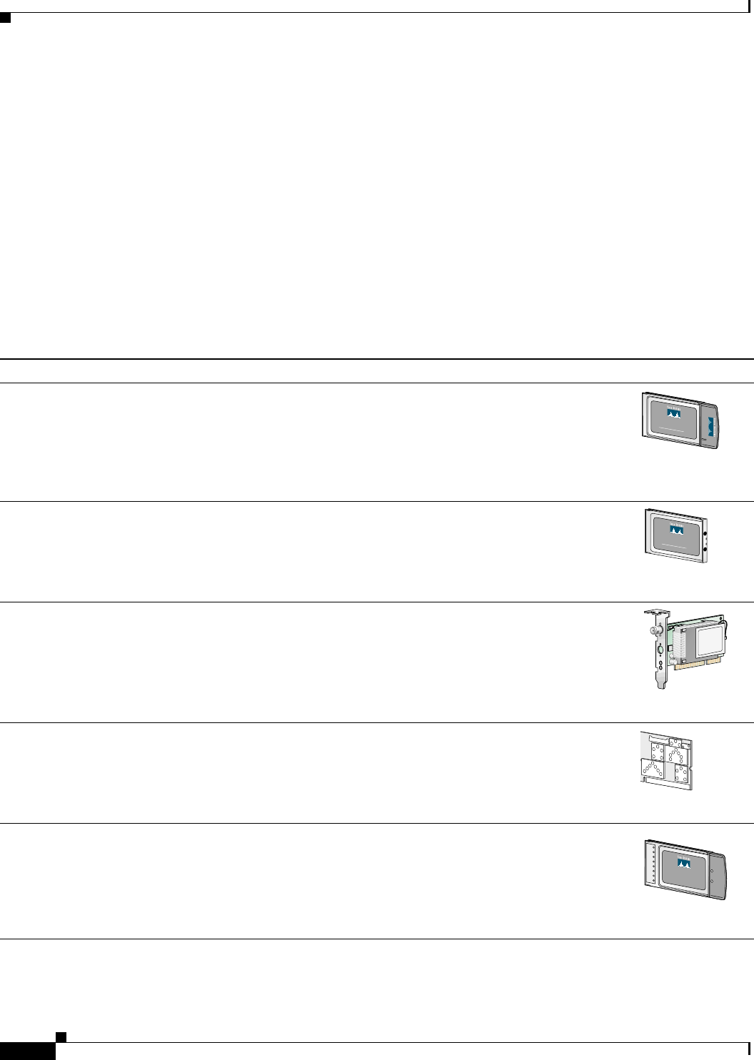
This document covers the five client adapters described in Table 1-1.
Table 1-1 Client Adapter Types
Client Adapter Model Number Description Illustration
PC card AIR-PCM3xx An IEEE 802.11b-compliant 2.4-GHz 11-Mbps PCMCIA card radio
module that can be inserted into any device equipped with an external
Type II or Type III PC card slot. Host devices can include laptops,
notebook computers, personal digital assistants, and handheld or
portable devices. The PC card is available in the 340 and 350 series.
LM card AIR-LMC3xx An IEEE 802.11b-compliant 2.4-GHz 11-Mbps PCMCIA card radio
module that is usually preinstalled in a device equipped with an
internal Type II or Type III PC card slot. Host devices usually include
handheld or portable devices. The LM card is available in the 340 and
350 series.
PCI card AIR-PCI3xx An IEEE 802.11b-compliant 2.4-GHz 11-Mbps client adapter card
radio module that can be inserted into any device equipped with an
empty PCI expansion slot, such as a desktop personal computer. The
PCI card is available in the 340 and 350 series.
Mini PCI card AIR-MPI350 An IEEE 802.11b-compliant 2.4-GHz 11-Mbps client adapter card
radio module that is preinstalled in a device equipped with an internal
Type IIIA mini PCI card slot, such as a laptop computer. The mini PCI
card is available only in the 350 series.
PC-Cardbus
card AIR-CB20A An IEEE 802.11a-compliant 5-GHz 54-Mbps client adapter card
radio module with a Cardbus interface that can be inserted into any
device equipped with an external Type II or Type III Cardbus slot.
Host devices can include laptops, notebook computers, personal
digital assistants, and handheld or portable devices.
CISCO AIRONET 340
SERIES
11 Mbps WIRELESS LAN ADAPTER
47519
CISCO AIRONET 340
SERIES
11 Mbps WIRELESS LAN ADAPTER
47893
65189
65190
74795

1-3
Cisco Aironet Wireless LAN Client Adapters Installation and Configuration Guide for Windows
OL-1394-06
Chapter 1 Product Overview Hardware Components
Note In the first three product model numbers, the first x represents the client adapter series (340 or 350), and
the second x indicates the wired equivalent privacy (WEP) level of the card, where 0 = no WEP
capability, 1 = 40-bit WEP, and 2 = 128-bit WEP. If the last two product model numbers contain K9, the
card is 128-bit WEP capable.
Terminology
The following terms are used throughout this document:
•client adapter—Refers to all five types of adapters.
•PC card, LM card,PCI card,mini PCI card, or PC-Cardbus card—Refers to a specific adapter.
•workstation (or station)—Refers to a computing device with an installed client adapter.
•infrastructure device—Refers to a device that connects client adapters to a wired LAN, such as an
access point, bridge, or base station. Throughout this document, access point is used to represent
infrastructure devices in general.
Hardware Components
The client adapter has three major hardware components: a radio, a radio antenna, and two LEDs.
Radio
Different radios are used for the 2.4-GHz and 5-GHz client adapters:
•The Cisco Aironet 340 and 350 series PC, LM, PCI, and mini PCI cards are IEEE 802.11b-compliant
client adapters. They contain a direct-sequence spread spectrum (DSSS) radio that operates in the
2.4-GHz Industrial Scientific Medical (ISM) license-free band. The 340 series 30-milliwatt (mW)
radio and the 350 series 100-mW radio transmit data over a half-duplex radio channel operating at
up to 11 Mbps. These cards operate with other IEEE 802.11b-compliant client devices in ad hoc (or
peer-to-peer) mode or with Cisco Aironet 340, 350, 1100, and 1200 Series Access Points (with a
2.4-GHz radio) and other IEEE 802.11b-compliant infrastructure devices in infrastructure mode.
They are approved for indoor and outdoor use.
DSSS technology distributes a radio signal over a wide range of frequencies and then returns the
signal to the original frequency range at the receiver. The benefit of this technology is its ability to
protect the data transmission from interference. For example, if a particular frequency encounters
noise or interference or both, enough redundancy is built into the signal on other frequencies that
the client adapter usually will still be successful in its transmission.
•The Cisco Aironet AIR-CB20A PC-Cardbus card is an IEEE 802.11a-compliant client adapter. It
contains an orthogonal frequency division multiplexing (OFDM) radio that operates in the
Unlicensed National Information Infrastructure (UNII) 1 and UNII 2 license-free bands located in
the lower 5-GHz portion of the radio frequency spectrum. The 20-mW radio transmits data over a
half-duplex radio channel operating at up to 54 Mbps. This card interoperates with other IEEE
802.11a-compliant client devices in ad hoc mode or with Cisco Aironet 1200 Series Access Points
(with a 5-GHz radio) and other IEEE 802.11a-compliant infrastructure devices in infrastructure
mode. It is approved for indoor use only except in the United States, which allows for outdoor use
on channels 52 through 64.

1-4
Cisco Aironet Wireless LAN Client Adapters Installation and Configuration Guide for Windows OL-1394-06
Chapter 1 Product Overview
Hardware Components
Radio Antenna
The type of antenna used depends on your client adapter:
•PC cards have an integrated, permanently attached diversity antenna. The benefit of the diversity
antenna system is improved coverage. The system works by allowing the card to switch and sample
between its two antenna ports in order to select the optimum port for receiving data packets. As a
result, the card has a better chance of maintaining the radio frequency (RF) connection in areas of
interference. The antenna is housed within the section of the card that hangs out of the PC card slot
when the card is installed.
•LM cards are shipped without an antenna; however, an antenna can be connected through the card’s
external connector.
•PCI cards are shipped with a 2-dBi dipole antenna that attaches to the card’s antenna connector.
However, other types of antennas may be used. PCI cards can be operated through only the primary
(or right) antenna port.
•Mini PCI cards are designed to be used with either one or two antennas, which connect to the card’s
two antenna connectors. If two antennas are used, the radio automatically selects the antenna that
presents the best RF signal. If only one antenna is used, the radio finds and uses it regardless of
which connector it is plugged into.
•PC-Cardbus cards have an integrated, permanently attached non-diversity antenna that contains two
antenna ports, one for transmitting and one for receiving. The card cannot switch and sample
between the ports. The antenna is housed within the section of the card that hangs out of the Cardbus
slot when the card is installed.
Note Refer to the Antenna Mode (Transmit and Receive) parameters in Table 5-4 and Table 5-5 for
information on setting the client adapter’s antenna mode.
Note External antennas used in combination with a power setting resulting in a radiated power level above 100
mW equivalent isotropic radiated power (EIRP) are not allowed for use within the European community
and other countries that have adopted the European R&TTE directive or the CEPT recommendation Rec
70.03 or both. For more details on legal combinations of power levels and antennas in those countries,
refer to the “Declaration of Conformity with Regard to the R&TTE Directive 1999/5/EC” section on
page C-4 and the “Maximum Power Levels and Antenna Gains” section on page D-4.
LEDs
The client adapters have two LEDs that glow or blink to indicate the status of the adapter or to convey
error messages. Refer to Chapter 10 for an interpretation of the LED codes.
Note Mini PCI cards do not have LEDs.

1-5
Cisco Aironet Wireless LAN Client Adapters Installation and Configuration Guide for Windows
OL-1394-06
Chapter 1 Product Overview Software Components
Software Components
The client adapter has three major software components: radio firmware, a driver, and client utilities.
These components are installed together by running a single Install Wizard file that is available from
Cisco.com. This file can be run on Windows 98, 98 SE, NT, 2000, Me, or XP and can be used with any
of the following client adapter types:
•340 and 350 series PC, LM, and PCI cards
•350 series mini PCI cards
•PC-Cardbus (CB20A) cards
Chapter 3 provides instructions on using the Install Wizard to install or upgrade these software
components.
Note Prior to the release of the Install Wizard file, each software component had to be installed separately.
This version of the Cisco Aironet Wireless LAN Client Adapters Installation and Configuration Guide
for Windows pertains specifically to versions of the software that are available through the Install
Wizard. If you are using, installing, or upgrading to versions of client adapter software that do not use
the Install Wizard, refer to version OL-1394-04 of this manual for information and instructions.
Radio Firmware
The firmware controls the client adapter’s radio. The client adapter is shipped with the firmware installed
in Flash memory. However, Cisco recommends that you always use the latest version. You can upgrade
the client adapter’s firmware in three ways:
•Through the Install Wizard—The Install Wizard automatically upgrades the client adapter’s
firmware to the version included in the Install Wizard file.
•Through the driver—The driver included in the Install Wizard file is also bundled with client adapter
firmware. Each time you insert a client adapter or reboot your computer, the driver loads and may
install the firmware with which it is bundled (if that firmware is newer than the firmware that is
currently installed in the adapter). You can use the Install Wizard’s Disable Firmware Checking
parameter or ACU’s Automatically Load New Firmware When NDIS Driver Is Updated parameter
to specify whether the driver upgrades the firmware. Refer to page 3-6 and page 9-10 for more
information.
•Through ACU—The Load Firmware icon or Load New Firmware menu option in ACU enables you
to upgrade the client adapter’s firmware from an image (*.img) file that contains only firmware.
Refer to the “Upgrading the Firmware” section on page 9-8 for more information.
Driver
The driver provides an interface between a computer running a Windows operating system and the client
adapter, thereby enabling Windows and the applications it runs to communicate with the adapter. The
driver must be installed before the adapter can be used.
1-6
Cisco Aironet Wireless LAN Client Adapters Installation and Configuration Guide for Windows OL-1394-06
Chapter 1 Product Overview
Software Components
Client Utilities
Two client utilities are available for use with Cisco Aironet client adapters: Aironet Client Utility (ACU)
and Aironet Client Monitor (ACM). These utilities are optional applications that interact with the radio
firmware to adjust client adapter settings and display information about the adapter.
ACU enables you to create configuration profiles for your client adapter and perform user-level
diagnostics. Because ACU performs a variety of functions, it is documented by function throughout this
manual. However, an overview of the utility is provided below to familiarize you with its interface.
ACM, which is accessible from an icon in the Windows system tray, provides a small subset of the
features available through ACU. Specifically, it enables you to access status information about your
client adapter and perform basic tasks. Chapter 8 provides detailed information and instructions on using
ACM.
Note If your computer is running Windows XP, you can configure your client adapter through the Windows
operating system instead of through ACU. Refer to Appendix E for information. However, ACU is
recommended for configuring the client adapter.
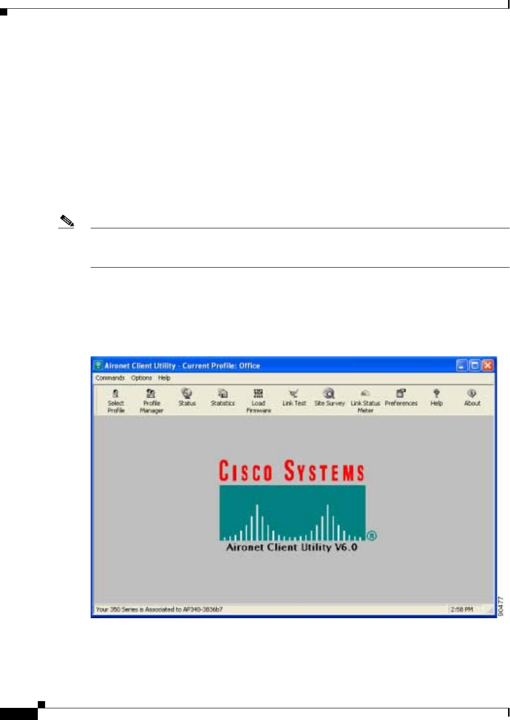
Overview of ACU
The Aironet Client Utility screen (see Figure 1-1) is ACU’s primary screen.
Figure 1-1 Aironet Client Utility Screen

1-7
Cisco Aironet Wireless LAN Client Adapters Installation and Configuration Guide for Windows
OL-1394-06
Chapter 1 Product Overview Software Components
The title bar at the top of the Aironet Client Utility screen shows the profile that is being used by the
client adapter.
The status bar at the bottom of the Aironet Client Utility screen reflects the current state of your client
adapter. The following states are possible, where radio_name is the client adapter type and ap_name is
the configured name of an access point:
•Your radio_name is Associated to ap_name
•Your radio_name is Not Associated!
•Authentication Started with ap_name
•Your radio_name is Authenticated to ap_name
•Authentication Failed with ap_name
•Your radio_name is in AdHoc Mode
•Your radio_name is being loaded with new firmware!
•The radio in your radio_name is turned OFF!
•Unable to read the status from your Wireless LAN Adapter!
•Your radio_name has a problem!
Note Some 340 series cards may improperly display a radio_name of 4800.
Note Aironet Extensions must be enabled on access points running Cisco IOS release 12.2(4)JA or
greater in order for the ap_name to appear in the status bar.
The information shown in the status bar is updated once per second.
The right side of the status bar shows the current time of day. If you set the clock to display seconds in
the Aironet Client Utility Preferences screen, the time includes seconds in addition to hours and minutes.
Note To enable the clock to display seconds, open ACU, click the Preferences icon or select
Preferences from the Options drop-down menu, check the Display Seconds on Clock check
box, and click OK.

1-8
Cisco Aironet Wireless LAN Client Adapters Installation and Configuration Guide for Windows OL-1394-06
Chapter 1 Product Overview
Network Configurations Using Client Adapters
Buttons on the ACU Screens
The buttons on the ACU screens are used to perform specific functions. Table 1-2 describes the most
common buttons.
Network Configurations Using Client Adapters
Client adapters can be used in a variety of network configurations. In some configurations, access points
provide connections to your network or act as repeaters to increase wireless communication range. The
maximum communication range is based on how you configure your wireless network.
This section describes and illustrates the two most common network configurations:
•Ad hoc wireless local area network (LAN)
•Wireless infrastructure with workstations accessing a wired LAN
For examples of more complex network configurations involving client adapters and access points, refer
to the documentation for your access point.
Note Refer to Chapter 5 for information on setting the client adapter’s network mode.
Table 1-2 Buttons on the ACU Screens
Button Description
Apply Saves any changes without exiting the screen
Cancel Exits the screen without saving any changes
Defaults Displays the default value of each parameter
Help Provides information on the screen and its parameters
OK Saves any changes and exits the screen
Start Initiates a test
Stop Stops a test that is running
1-9
Cisco Aironet Wireless LAN Client Adapters Installation and Configuration Guide for Windows
OL-1394-06
Chapter 1 Product Overview Network Configurations Using Client Adapters
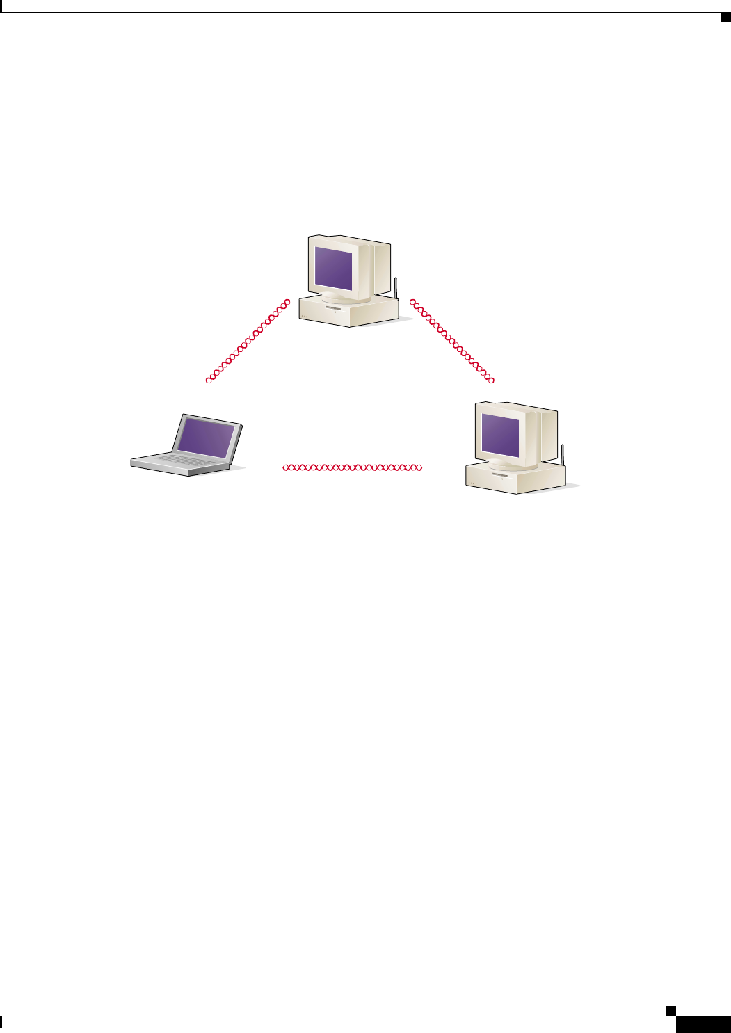
Ad Hoc Wireless LAN
An ad hoc (or peer-to-peer) wireless LAN (see Figure 1-2) is the simplest wireless LAN configuration.
In a wireless LAN using an ad hoc network configuration, all devices equipped with a client adapter can
be linked together and communicate directly with each other. The use of an infrastructure device, such
as an access point, is not required.
Figure 1-2 Ad Hoc Wireless LAN
47520
1-10
Cisco Aironet Wireless LAN Client Adapters Installation and Configuration Guide for Windows OL-1394-06
Chapter 1 Product Overview
Network Configurations Using Client Adapters
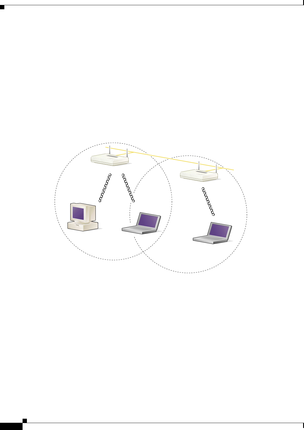
Wireless Infrastructure with Workstations Accessing a Wired LAN
A microcellular network can be created by placing two or more access points on a LAN. Figure 1-3
shows a microcellular network with workstations accessing a wired LAN through several access points.
This configuration is useful with portable or mobile stations because it allows them to be directly
connected to the wired network even while moving from one microcell domain to another. This process
is transparent, and the connection to the file server or host is maintained without disruption. The mobile
station stays connected to an access point as long as it can. However, once the transfer of data packets
needs to be retried or beacons are missed, the station automatically searches for and associates to another
access point. This process is referred to as seamless roaming.
Figure 1-3 Wireless Infrastructure with Workstations Accessing a Wired LAN
Access Point
(Root Unit)
Access Point
(Root Unit)
5835
Wired LAN

CHAPTER
2-1
Cisco Aironet Wireless LAN Client Adapters Installation and Configuration Guide for Windows
OL-1394-06
2
Preparing for Installation
This chapter provides information that you need to know before installing a client adapter.
The following topics are covered in this chapter:
•Safety information, page 2-2
•Unpacking the Client Adapter, page 2-3
•System Requirements, page 2-4
•Site Requirements, page 2-5

2-2
Cisco Aironet Wireless LAN Client Adapters Installation and Configuration Guide for Windows OL-1394-06
Chapter 2 Preparing for Installation
Safety information
Safety information
Follow the guidelines in this section to ensure proper operation and safe use of the client adapter.
FCC Safety Compliance Statement
The FCC, with its action in ET Docket 96-8, has adopted a safety standard for human exposure to RF
electromagnetic energy emitted by FCC-certified equipment. When used with approved Cisco Aironet
antennas, Cisco Aironet products meet the uncontrolled environmental limits found in OET-65 and ANSI
C95.1, 1991. Proper operation of this radio device according to the instructions in this publication will
result in user exposure substantially below the FCC recommended limits.
Safety Guidelines
•Do not touch or move the antenna while the unit is transmitting or receiving.
•Do not hold any component containing a radio such that the antenna is very close to or touching any
exposed parts of the body, especially the face or eyes, while transmitting.
•Do not operate the radio or attempt to transmit data unless the antenna is connected; otherwise, the
radio may be damaged.
•High-gain, wall-mount, or mast-mount antennas are designed to be professionally installed and
should be located at a minimum distance of 12 inches (30 cm) or more from the body of all persons.
Please contact your professional installer, VAR, or antenna manufacturer for proper installation
requirements.
•Use in specific environments:
–
The use of wireless devices in hazardous locations is limited to the constraints posed by the
safety directors of such environments.
–
The use of wireless devices on airplanes is governed by the Federal Aviation Administration
(FAA).
–
The use of wireless devices in hospitals is restricted to the limits set forth by each hospital.

2-3
Cisco Aironet Wireless LAN Client Adapters Installation and Configuration Guide for Windows
OL-1394-06
Chapter 2 Preparing for Installation Unpacking the Client Adapter
Warnings
Observe the following warnings when operating the client adapter:
Warning
Do not operate your wireless network device near unshielded blasting caps or in an explosive
environment unless the device has been modified to be especially qualified for such use.
Warning
In order to comply with FCC radio frequency (RF) exposure limits, dipole antennas should be located
at a minimum of 7.9 inches (20 cm) or more from the body of all persons.
Warning
In order to comply with RF exposure limits established in the ANSI C95.1 standards, it is recommended
when using a laptop with a PC card client adapter that the adapter’s integrated antenna is positioned
more than 2 inches (5 cm) from your body or nearby persons during extended periods of transmitting
or operating time. If the antenna is positioned less than 2 inches (5 cm) from the user, it is
recommended that the user limit exposure time.
Translated versions of these safety warnings are provided in Appendix B.
Unpacking the Client Adapter
Follow these steps to unpack the client adapter:
Step 1 Open the shipping container and carefully remove the contents.
Step 2 Return all packing materials to the shipping container and save it.
Step 3 Ensure that all items listed in the “Package Contents” section below are included in the shipment. Check
each item for damage.
Note If any item is damaged or missing, notify your authorized Cisco sales representative. Any remote
antenna and its associated wiring are shipped separately.
Package Contents
Each client adapter is shipped with the following items:
•Standard 2-dBi dipole antenna (PCI cards only)
•Quick Start Guide: Cisco Aironet Wireless LAN Client Adapters
•Cisco Aironet Wireless LAN Client Adapters CD (for 2.4-GHz client adapters) or
Cisco Aironet 5-GHz 54-Mbps Wireless Adapters CD (for 5-GHz client adapters)
•Cisco product registration card

2-4
Cisco Aironet Wireless LAN Client Adapters Installation and Configuration Guide for Windows OL-1394-06
Chapter 2 Preparing for Installation
System Requirements
System Requirements
In addition to the items shipped with the client adapter, you also need the following in order to install
and use the adapter:
•One of the following computing devices running Windows 98, 98 SE, NT, 2000, Me, or XP:
–
Laptop, notebook, or portable or handheld device equipped with a Type II or Type III PC card
slot or Cardbus slot
–
Desktop personal computer equipped with an empty PCI expansion slot
–
Handheld or portable device with an embedded LM card
–
Laptop or other computing device with an embedded mini PCI card
Note PC-Cardbus cards are not supported for use with Windows NT.
Note Cisco recommends using a display with a minimum resolution of 800 x 600 pixels.
Note All drivers and supporting software (Card and Socket Services) for the PC card slot or
Cardbus slot must be loaded and configured.
•35 MB of free hard disk space (minimum)
•A maximum of eight network connections if your computer is running Windows 98 or 98 SE
Note Windows 98 and 98 SE limit your computer’s network connections. If you try to install a
client adapter when eight network devices (such as a PCMCIA Ethernet card, dial-up
adapter, VPN adapter, docking station Ethernet card, etc.) are already connected to your
computer, the new adapter cannot establish a network connection.
•Windows NT Service Pack 6 or greater if your computer is running Windows NT
•A Phillips screwdriver (for PCI cards)
•The Microsoft 802.1X supplicant, if your wireless network uses EAP-TLS, PEAP, or EAP-SIM
authentication
•If your wireless network uses PEAP authentication with a One-Time Password (OTP) user database:
–
SofToken version 1.3, 2.0, or greater from Secure Computing; SecurID version 2.5 from RSA;
or hardware token from OTP vendors
–
Your software token PIN or hardware token password

2-5
Cisco Aironet Wireless LAN Client Adapters Installation and Configuration Guide for Windows
OL-1394-06
Chapter 2 Preparing for Installation Site Requirements
•If your wireless network uses EAP-SIM authentication:
–
PCSC-compliant smartcard reader installed in your computer’s Type II or Type III PC card slot
–
Gemplus SIM+ smartcard inserted in the reader
–
The SIM card’s PIN
Note The EAP-SIM supplicant included in the Install Wizard file supports only Gemplus SIM+
cards; however, an updated supplicant is available that supports standard GSM-SIM cards as
well as more recent versions of the EAP-SIM protocol. The new supplicant is available for
download from the ftpeng FTP server at the following URL:
ftp://ftpeng.cisco.com/ftp/pwlan/eapsim/CiscoEapSim.dll
•The following information from your system administrator:
–
The logical name for your workstation (also referred to as client name)
–
The protocols necessary to bind to the client adapter
–
The case-sensitive service set identifier (SSID) for your RF network
–
If your computer is not connected to a DHCP server, the IP address, subnet mask, and default
gateway address of your computer
–
The wired equivalent privacy (WEP) keys of the access points with which your client adapter
will communicate, if your wireless network uses static WEP for security
–
The username and password for your network account
Site Requirements
This section discusses the site requirements for both infrastructure and client devices.
For Infrastructure Devices
Because of differences in component configuration, placement, and physical environment, every
network application is a unique installation. Therefore, before you install any wireless infrastructure
devices (such as access points, bridges, and base stations, which connect your client adapters to a wired
LAN), a site survey must be performed to determine the optimum placement of these devices to
maximize range, coverage, and network performance. Appendix F, which is provided for people who
are responsible for conducting a site survey, explains how ACU’s site survey tool can be used to
determine the best placement for infrastructure devices within a wireless network.
Note Infrastructure devices are installed and initially configured prior to client devices.

2-6
Cisco Aironet Wireless LAN Client Adapters Installation and Configuration Guide for Windows OL-1394-06
Chapter 2 Preparing for Installation
Site Requirements
For Client Devices
Because the client adapter is a radio device, it is susceptible to RF obstructions and common sources of
interference that can reduce throughput and range. Follow these guidelines to ensure the best possible
performance:
•Install the client adapter in an area where large steel structures such as shelving units, bookcases,
and filing cabinets will not obstruct radio signals to and from the client adapter.
•Install the client adapter away from microwave ovens. Microwave ovens operate on the same
frequency as the client adapter and can cause signal interference.

CHAPTER
3-1
Cisco Aironet Wireless LAN Client Adapters Installation and Configuration Guide for Windows
OL-1394-06
3
Installing the Client Adapter
This chapter provides instructions for installing the client adapter’s firmware, driver, utilities, and
security modules.
The following topics are covered in this chapter:
•Installing or Upgrading the Client Adapter Software, page 3-2
•Verifying Installation, page 3-22
•Deciding How to Configure Your Client Adapter (Windows XP Only), page 3-22
•Selecting Among Several Installed Client Adapters, page 3-24

3-2
Cisco Aironet Wireless LAN Client Adapters Installation and Configuration Guide for Windows OL-1394-06
Chapter 3 Installing the Client Adapter
Installing or Upgrading the Client Adapter Software
Installing or Upgrading the Client Adapter Software
This section enables you to install or upgrade Cisco Aironet client adapter firmware, drivers, utilities,
and security modules from a self-extracting executable file named
Windows-Client-Installation-Wizard-v.exe, where vrepresents the version number.
Follow the instructions below to install or upgrade client adapter software on a computer running
Windows 98, 98 SE, 2000, Me, or XP. If your computer is running Windows NT, follow the instructions
on page 3-12.
Caution The Install Wizard automatically upgrades client adapter firmware to the version included in the Install
Wizard file. Both of the client adapter’s LEDs light continuously while the firmware upgrade occurs. Do
not eject the client adapter while the firmware is being upgraded.
Note The Install Wizard file is not yet available on the CD that ships with Cisco Aironet client adapters. If
you are installing or upgrading to versions of client adapter software that do not use the Install Wizard
file, refer to version OL-1394-04 of this manual for installation, configuration, and operation
instructions.
Installing or Upgrading the Client Adapter Software on Windows 98, 98 SE, 2000,
Me, or XP
Follow the steps below to install or upgrade client adapter software components on a computer running
Windows 98, 98 SE, 2000, Me, or XP.
Note Windows Me and XP come with a driver that is installed automatically the first time you insert a PC,
LM, or PCI card. Follow the procedure below to upgrade this driver to the latest one available.
Step 1 Use your computer’s web browser to access the following URL:
http://www.cisco.com/public/sw-center/sw-wireless.shtml
Step 2 Select Option #2: Aironet Wireless Software Display Tables.
Note You can download software from the Software Selector tool instead of the display tables. To do
so, select Option #1: Aironet Wireless Software Selector, follow the instructions on the
screen, and go to Step 6.
Step 3 Select Cisco Aironet Wireless LAN Client Adapters.
Step 4 Under Aironet Client Adapter Installation Wizard (For Windows), select Aironet Client Adapter
Installation Wizard for Windows.
Step 5 Select the Install Wizard file with the greatest version number.
Step 6 Read and accept the terms and conditions of the Software License Agreement.
Step 7 Select the file again to download it.
Step 8 Save the file to your computer’s hard drive.
3-3
Cisco Aironet Wireless LAN Client Adapters Installation and Configuration Guide for Windows
OL-1394-06
Chapter 3 Installing the Client Adapter Installing or Upgrading the Client Adapter Software
Step 9 Follow the instructions in Chapter 9 to insert the client adapter into your computer, if it is not already
inserted. The instructions are different for PC cards, PC-Cardbus cards, and PCI cards.
Caution Do not eject your client adapter at any time during the installation process, including during the reboot.
Step 10 If a driver is not currently installed for your client adapter, the Found New Hardware Wizard screen
appears. Click Cancel.
Step 11 Find the Install Wizard file using Windows Explorer, double-click it, and extract its files to a folder.
Note To extract the files, click Browse on the WinZip Self-Extractor screen, select the folder in which
you want the files to be placed, and click OK and Unzip. After the files are extracted, click OK
to close the screen.
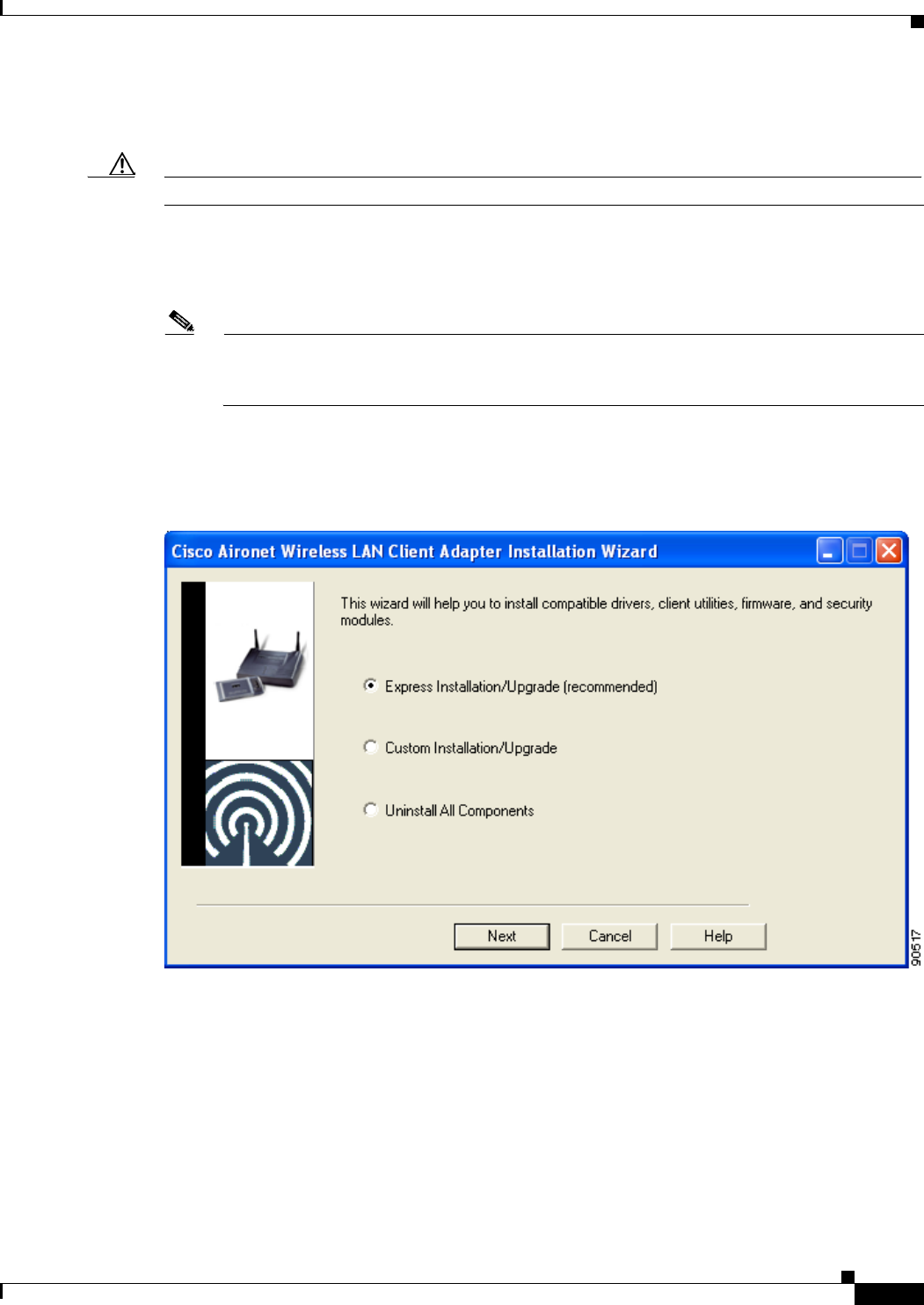
Step 12 Close Windows Explorer. The Cisco Aironet Wireless LAN Client Adapter Installation Wizard screen
appears (see Figure 3-1).
Figure 3-1 Cisco Aironet Wireless LAN Client Adapter Installation Wizard Screen
3-4
Cisco Aironet Wireless LAN Client Adapters Installation and Configuration Guide for Windows OL-1394-06
Chapter 3 Installing the Client Adapter
Installing or Upgrading the Client Adapter Software
Step 13 Select one of the following options on the Cisco Aironet Wireless LAN Client Adapter Installation
Wizard screen and click Next:
Note To ensure compatibility among software components, Cisco recommends that you perform an
express installation. If you perform a custom installation, Cisco recommends that you install all
components.
•Express Installation/Upgrade (recommended)—Silently installs the client adapter firmware,
drivers, client utilities, and security modules using the default values listed in Table 3-1.
•Custom Installation/Upgrade—Enables you to specify which software components are installed
and to change the default values of certain parameters.
Step 14 If a message appears indicating that you may be required to restart your computer at the end of the
installation process, click OK.
Note If you click Cancel, the installation process terminates.
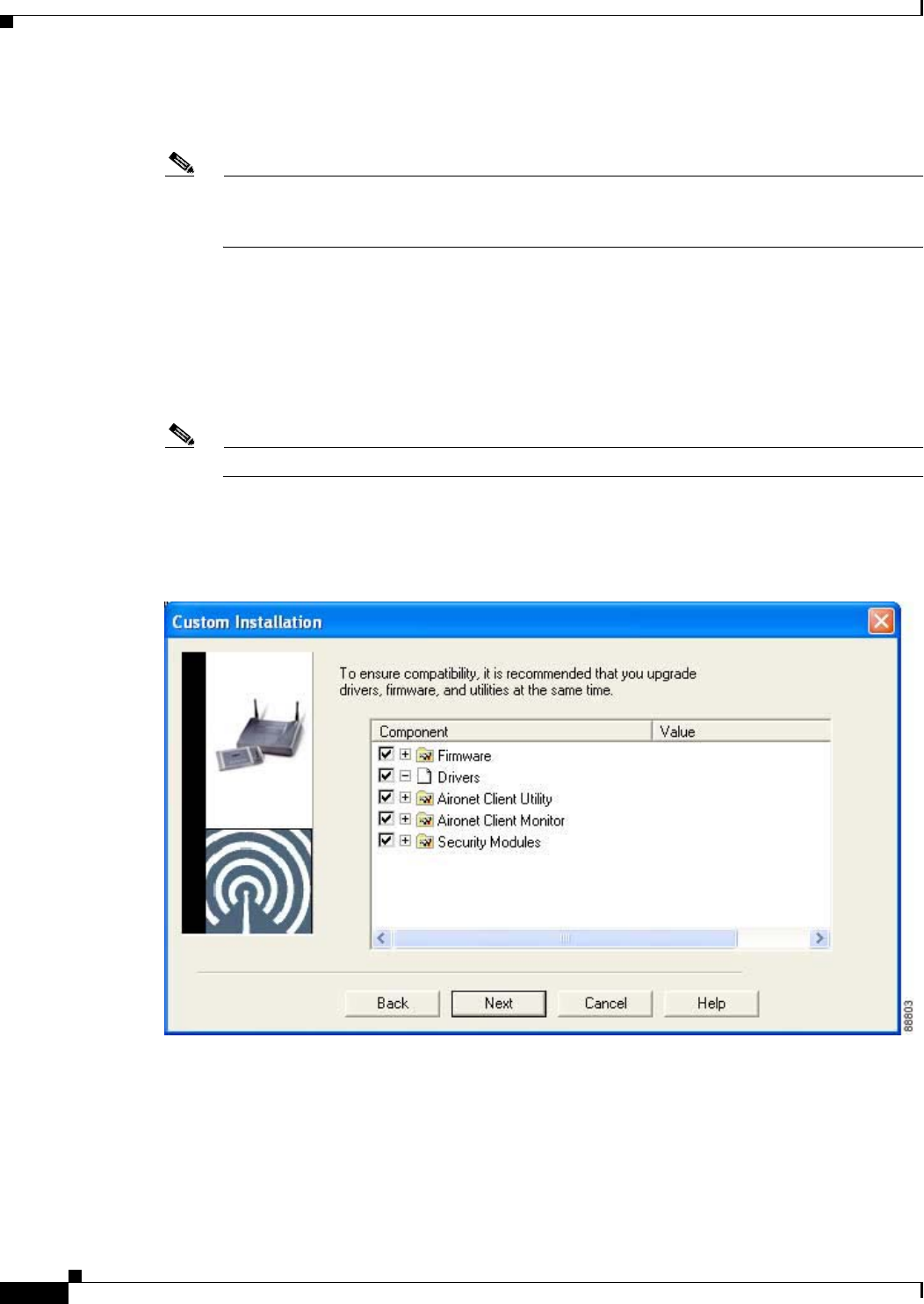
Step 15 If you selected an express installation, go to Step 17. If you selected a custom installation, the Custom
Installation screen appears (see Figure 3-2).
Figure 3-2 Custom Installation Screen

3-5
Cisco Aironet Wireless LAN Client Adapters Installation and Configuration Guide for Windows
OL-1394-06
Chapter 3 Installing the Client Adapter Installing or Upgrading the Client Adapter Software
Step 16 Follow the steps below to make selections on this screen.
a. Make sure a check mark appears beside every software component that you want to install. For every
component that is checked, the Install Wizard will install its version of that component. Every
component that is not checked will remain as it currently is on your system.
Note Click the + sign beside the Security Modules option to reveal the available security
components.
Note Some components are dependent on others. Therefore, when you select or deselect these
components, the settings of other components may change. A dependency notice appears
when this occurs.
b. Click the + sign beside each component to view additional parameters. The current value of each
parameter appears in the Value field.
c. To change the value of any parameter, click its current value in the Value field. A screen appears that
lets you change the existing value.
d. Enter or select a new value and click OK.Table 3-1 describes each component and its parameters
and lists any default value.

3-6
Cisco Aironet Wireless LAN Client Adapters Installation and Configuration Guide for Windows OL-1394-06
Chapter 3 Installing the Client Adapter
Installing or Upgrading the Client Adapter Software
Table 3-1 Software Components and Their Parameters
Component or Parameter Description
Firmware Installs the firmware version included in the Install Wizard file.
Default: Checked
Disable Firmware
Checking The Disable Firmware Checking parameter affects the firmware that
is bundled with the driver, not the firmware that is included in the
Install Wizard. This parameter controls whether the driver (whenever
it loads) installs the firmware with which it is bundled.
Note The driver loads each time you insert a client adapter or
reboot your computer.
Options: Yes or No
Default: Yes
Disable Firmware Checking Description
Yes Prevents the driver from installing the
firmware with which it is bundled,
enabling the client adapter to retain its
current firmware version.
No Causes the driver to install the firmware
with which it is bundled if that firmware is
newer than the firmware that is currently
installed in the client adapter.
Note The Disable Firmware Checking parameter is functionally
equivalent to the Automatically Load New Firmware When
NDIS Driver Is Updated parameter on the ACU Preferences
screen. The parameter that is set last is the one that governs
how the driver behaves. Refer to the “Preventing the Driver
from Upgrading the Firmware” section on page 9-10 for
additional information.
Note The Disable Firmware Checking parameter is available in
Install Wizard version 1.1 or greater.
Drivers Installs the driver version included in the Install Wizard file.
Default: Checked
Aironet Client Utility Installs the ACU version included in the Install Wizard file.
Default: Checked
Installation Path Determines the path where the ACU software will be installed. You
can change the default by entering a new path.
Default: C:\Program Files\Cisco Systems\Aironet Client Utility
Program Folder Determines the program folder where the ACU software will be
installed. You can change the default by entering a new folder name.
Default: Cisco Systems

3-7
Cisco Aironet Wireless LAN Client Adapters Installation and Configuration Guide for Windows
OL-1394-06
Chapter 3 Installing the Client Adapter Installing or Upgrading the Client Adapter Software
Place Icon on Desktop Causes the installation program to add an ACU icon to your
computer’s desktop to provide quick access to the utility.
Options: Yes or No
Default: Yes
Allow Non-Administrator
Users to Save Settings to
the Registry
Enables users without administrative rights to modify profiles in ACU
and save them to the registry on computers running Windows 2000 or
XP.
Options: Yes or No
Default: Yes
Note This option is not available for Windows 98, 98 SE, and Me
because these versions of Windows do not support different
classes of users.
Aironet Client Monitor Installs the ACM version included in the Install Wizard file.
Default: Checked
Installation Path Determines the path where the ACM software will be installed. You
can change the default by entering a new path.
Default: C:\Program Files\Cisco Systems\Aironet Client Monitor
Program Folder Determines the program folder where the ACM software will be
installed. You can change the default by entering a new folder name.
Default: Cisco Systems
Auto Start Determines whether ACM starts automatically every time Windows
boots.
Options: Yes or No
Default: Yes
Note If you select No, you can later activate ACM by using
Windows Explorer to find the path where the ACM software
is installed and double-clicking ACUMon.exe.
Start After Install Determines whether ACM starts automatically after ACM is installed.
Options: Yes or No
Default: Yes
Note If you select No, you can later activate ACM by using
Windows Explorer to find the path where the ACM software
is installed and double-clicking ACUMon.exe.
Table 3-1 Software Components and Their Parameters (continued)
Component or Parameter Description

3-8
Cisco Aironet Wireless LAN Client Adapters Installation and Configuration Guide for Windows OL-1394-06
Chapter 3 Installing the Client Adapter
Installing or Upgrading the Client Adapter Software
Program Feature Overrides Determines which ACM components are enabled. If any components
are not selected now and you later want to use them, you must run this
installation program again and enable them.
Components: See the table below
Options per component: Enable or Disable
Default per component: Enable
Component Description
About Box (Help) Displays the ACM version number and
enables you to access the online help.
Exit Program Closes ACM for all client adapters.
Launch Aironet Client
Utility Activates ACU, if it is installed.
Troubleshooting Activates the troubleshooting utility,
which enables you to identify and resolve
configuration and association problems
with your client adapter.
Preferences Enables you to determine when ACM runs
and to select the options that appear on the
ACM pop-up menu.
Turn Radio On/Off Turns the client adapter’s radio on or off.
Reauthenticate Forces your client adapter to try to
reauthenticate using the username and
password of the current profile.
Select Profile Enables you to select the active profile for
your client adapter.
Auto Profile Selection Causes the client adapter’s driver to
automatically select a profile from the list
of profiles that were set up in ACU to be
included in auto profile selection.
Other Configuration
Application Enables an application other than ACU to
configure the client adapter.
Show Connection Status Provides information on the current status
of your client adapter.
Menu Options (Defaults) Determines which options are displayed on the ACM pop-up menu.
Menu options: About Box (Help), Exit Program, Launch Aironet
Client Utility, Troubleshooting, Turn Radio On/Off,
Reauthenticate, Select Profile, Show Connection
Status
Options per menu option: Show or Hide
Default per menu option: Show
Table 3-1 Software Components and Their Parameters (continued)
Component or Parameter Description

3-9
Cisco Aironet Wireless LAN Client Adapters Installation and Configuration Guide for Windows
OL-1394-06
Chapter 3 Installing the Client Adapter Installing or Upgrading the Client Adapter Software
Security Modules
LEAP Installs the LEAP supplicant version included in the Install Wizard
file. Installing the LEAP supplicant enables you to create a profile in
ACU that uses LEAP authentication. If this option is not selected now
and you later want to create a profile that uses LEAP, you must run
this installation program again and select this option.
Default: Checked
Note Refer to Chapter 5 for information on enabling LEAP.
Note If you select LEAP on a Windows 98 or 98 SE device, a
Microsoft hot fix is installed during installation of the LEAP
security module to fix two problems related to the use of
LEAP. Refer to Chapter 10 for more information on the hot
fix.
Note If you select LEAP on a Windows XP device, Windows XP’s
fast user switching feature is disabled.
Allow Saved LEAP
User Name and
Password
Enables you to create a profile in ACU that uses a saved (rather than
temporary) username and password for LEAP authentication. When
such a profile is used, the saved username and password are used to
start the LEAP authentication process, and you are not prompted to
enter them.
Options: Yes or No
Default: Yes
EAP-SIM Installs the EAP-SIM supplicant version included in the Install
Wizard file. Installing the EAP-SIM supplicant enables the client to
support EAP-SIM authentication. If this option is not selected now
and you later want to use EAP-SIM, you must run this installation
program again and select this option.
Default: Unchecked
Note Refer to Chapter 5 for information on enabling EAP-SIM.
Note To enable EAP-SIM authentication, your computer must run
Windows 2000 with the Microsoft 802.1X supplicant
installed or Windows XP.
Note If you installed the new EAP-SIM supplicant from the ftpeng
FTP server, make sure the EAP-SIM option is not selected.
Otherwise, the EAP-SIM supplicant included in the Install
Wizard file overwrites the new supplicant’s settings.
Table 3-1 Software Components and Their Parameters (continued)
Component or Parameter Description

3-10
Cisco Aironet Wireless LAN Client Adapters Installation and Configuration Guide for Windows OL-1394-06
Chapter 3 Installing the Client Adapter
Installing or Upgrading the Client Adapter Software
e. When you are finished making selections, click Next.
Step 17 The installation process begins, and you are notified as each component is installed. Perform one of the
following:
•If the following message appears, click OK and then reboot your computer: “The installation will
complete and applications will be installed when a wireless LAN client adapter is inserted. If an
adapter is already inserted, remove and reinsert the adapter or reboot the machine.”
The Found New Hardware screen appears. Depending on your computer’s operating system, you
may have to click Next. The driver and other software components are installed. Then an ACM icon
appears in the Windows system tray (unless you changed the default value during installation).
Perform one of the following:
–
If a message appears asking if you wish to reboot now, click Yes.
Note To ensure that your client adapter software is installed properly, Cisco recommends that
you click Yes to reboot your computer now.
–
If a message appears indicating that the system is about to reboot, click OK and allow your
computer to restart.
•If a message appears asking if you wish to reboot now, click Yes.
Note To ensure that your client adapter software is installed properly, Cisco recommends that you
click Yes to reboot your computer now.
PEAP Installs the PEAP supplicant version included in the Install Wizard
file. Installing the PEAP supplicant enables the client to support
PEAP authentication. If this option is not selected now and you later
want to use PEAP, you must run this installation program again and
select this option.
Default: Unchecked
Note Refer to Chapter 5 for information on enabling PEAP.
Note To enable Cisco PEAP authentication, your computer must
run Windows 2000 with the Microsoft 802.1X supplicant
installed or Windows XP.
Note Service Pack 1 for Windows XP and the Microsoft 802.1X
supplicant for Windows 2000 include Microsoft’s PEAP
supplicant, which supports a Windows username and
password only and does not interoperate with Cisco’s PEAP
supplicant. To use Cisco’s PEAP supplicant, install the Install
Wizard file after Service Pack 1 for Windows XP or the
Microsoft 802.1X supplicant for Windows 2000. Otherwise,
Cisco’s PEAP supplicant is overwritten by Microsoft’s PEAP
supplicant.
Table 3-1 Software Components and Their Parameters (continued)
Component or Parameter Description

3-11
Cisco Aironet Wireless LAN Client Adapters Installation and Configuration Guide for Windows
OL-1394-06
Chapter 3 Installing the Client Adapter Installing or Upgrading the Client Adapter Software
•If a message appears indicating that the system is about to reboot, click OK and allow your computer
to restart.
Step 18 If you want to install a second client adapter, allow your computer to reboot completely; then insert the
second adapter into your computer. Depending on your computer’s operating system, one of the
following scenarios occurs:
•The Found New Hardware Wizard screen appears. Depending on your computer’s operating system,
you may have to click Next. The driver and other software components are installed, and another
ACM icon appears in the Windows system tray. Click Yes or OK when a message appears about
rebooting your computer.
Note To ensure that your client adapter software is installed properly, Cisco recommends that you
reboot your computer now.
•The driver and other software components are installed, and another ACM icon appears in the
Windows system tray. Click Yes or OK when a message appears about rebooting your computer.
Note To ensure that your client adapter software is installed properly, Cisco recommends that you
reboot your computer now.
Step 19 If your computer is not connected to a DHCP server and you plan to use TCP/IP, follow the steps below
for your operating system. If you have more than one client adapter installed, repeat this step for each
adapter.
•Windows 98, 98 SE, and Me—Double-click My Computer,Control Panel, and Network. Select
TCP/IP > Cisco Systems Wireless LAN Adapter. Click Properties, select Specify an IP address,
and enter the IP address, subnet mask, and default gateway address of your computer (which can be
obtained from your system administrator). Click OK. In the Network window, click OK.
•Windows 2000—Double-click My Computer,Control Panel, and Network and Dial-up
Connections. Right-click Local Area Connection x (where x represents the number of the
connection). Click Properties,Internet Protocol (TCP/IP), and Properties. Click Use the
following IP address and enter the IP address, subnet mask, and default gateway address of your
computer (which can be obtained from your system administrator). Click OK. In the Local Area
Connection Properties window, click OK.
•Windows XP—Right-click Wireless Network Connection and click Properties. Select Internet
Protocol (TCP/IP) and click Properties. Select Use the following IP address and enter the IP
address, subnet mask, and default gateway address of your computer (which can be obtained from
your system administrator). Click OK
Step 20 If you are prompted to restart your computer, click Yes.
Step 21 Go to the “Verifying Installation” section on page 3-22 to determine if the installation was successful.
After you verify installation, go to Chapter 4 if you want to create profiles for your client adapter.

3-12
Cisco Aironet Wireless LAN Client Adapters Installation and Configuration Guide for Windows OL-1394-06
Chapter 3 Installing the Client Adapter
Installing or Upgrading the Client Adapter Software
Installing or Upgrading the Client Adapter Software on Windows NT
Follow the steps below to install or upgrade client adapter software components on a computer running
Windows NT.
Note PC-Cardbus cards are not supported for use with Windows NT.
Note This procedure requires that your computer has Windows NT Service Pack 6 or greater.
Step 1 Use your computer’s web browser to access the following URL:
http://www.cisco.com/public/sw-center/sw-wireless.shtml
Step 2 Select Option #2: Aironet Wireless Software Display Tables.
Note You can download software from the Software Selector tool instead of the display tables. To do
so, select Option #1: Aironet Wireless Software Selector, follow the instructions on the
screen, and go to Step 6.
Step 3 Select Cisco Aironet Wireless LAN Client Adapters.
Step 4 Under Aironet Client Adapter Installation Wizard (For Windows), select Aironet Client Adapter
Installation Wizard for Windows.
Step 5 Select the Install Wizard file with the greatest version number.
Step 6 Read and accept the terms and conditions of the Software License Agreement.
Step 7 Select the file again to download it.
Step 8 Save the file to your computer’s hard drive.
Step 9 If you are installing a PC or LM card, follow the steps below to obtain an available interrupt request
(IRQ):
a. Select Start > Programs > Administrative Tools > Windows NT Diagnostics.
b. Click the Resources tab.
c. Click the IRQ button.
d. The used IRQs are listed in numerical order along the left side of the Resources window. Write down
the number of an IRQ that is not being used. You will need this IRQ for Step 21.
Step 10 If you are installing a PC or LM card, double-click My Computer,Control Panel, and Devices. Scroll
down and select Pcmcia. Click Startup, select Automatic, and click OK.
Step 11 Follow the instructions in Chapter 9 to insert the client adapter into your computer if it is not already
inserted. The instructions are different for PC cards and PCI cards.
Caution Do not eject your client adapter at any time during the installation process, including during the reboot.
Step 12 If the Windows NT Wizard screen appears, click Exit.
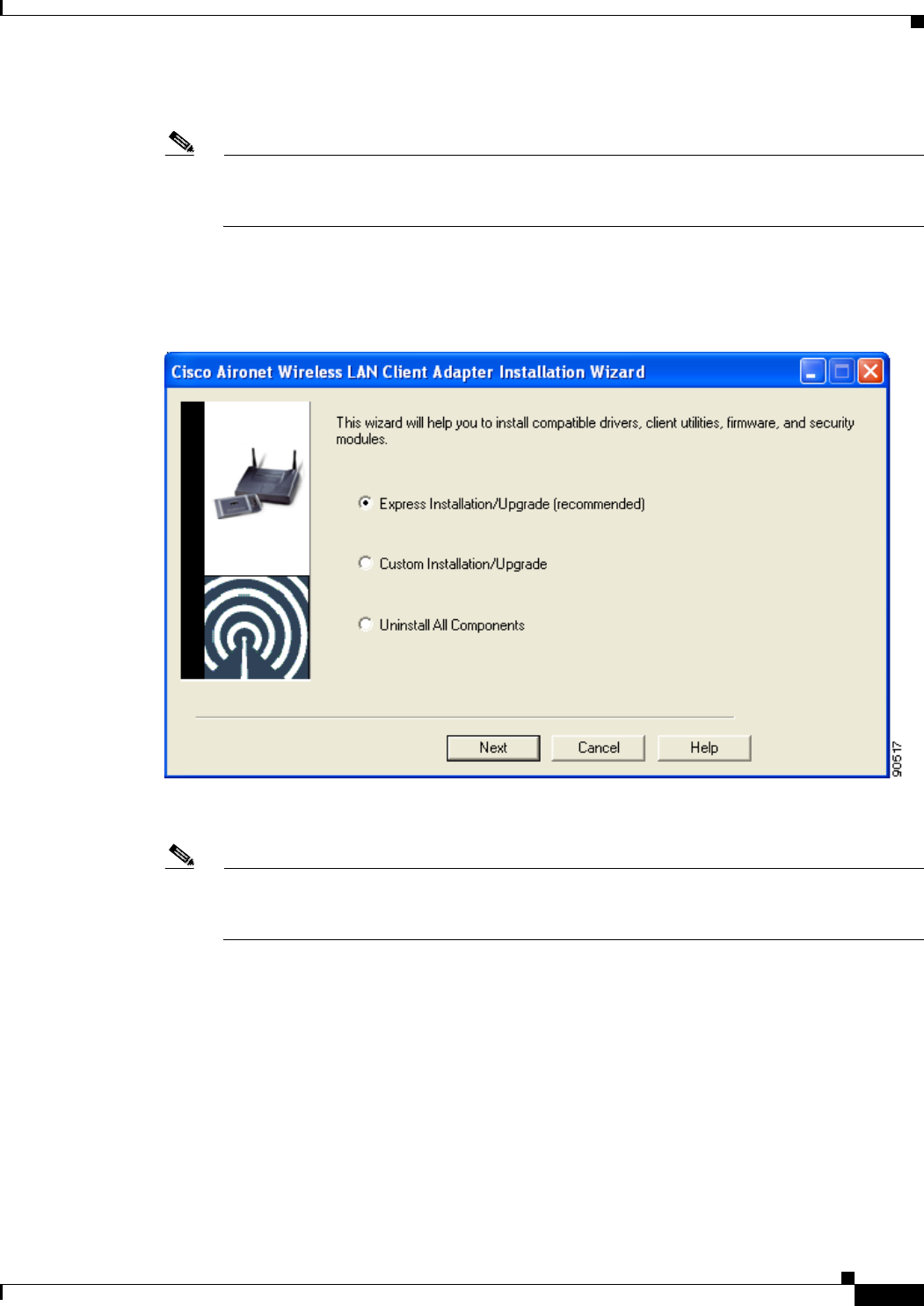
3-13
Cisco Aironet Wireless LAN Client Adapters Installation and Configuration Guide for Windows
OL-1394-06
Chapter 3 Installing the Client Adapter Installing or Upgrading the Client Adapter Software
Step 13 Find the Install Wizard file using Windows Explorer, double-click it, and extract its files to a folder.
Note To extract the files, click Browse on the WinZip Self-Extractor screen, select the folder in which
you want the files to be placed, and click OK and Unzip. After the files are extracted, click OK
to close the screen.
Step 14 Close Windows Explorer. The Cisco Aironet Wireless LAN Client Adapter Installation Wizard screen
appears (see Figure 3-3).
Figure 3-3 Cisco Aironet Wireless LAN Client Adapter Installation Wizard Screen
Step 15 Select one of the following options and click Next:
Note To ensure compatibility among software components, Cisco recommends that you perform an
express installation. If you perform a custom installation, Cisco recommends that you install all
components.
•Express Installation/Upgrade (recommended)—Silently installs the client adapter firmware,
drivers, client utilities, and security modules using the default values listed in Table 3-2.
•Custom Installation/Upgrade—Enables you to specify which software components are installed
and to change the default values of certain parameters.
Step 16 A screen appears with a list of available drivers (see Figure 3-4).
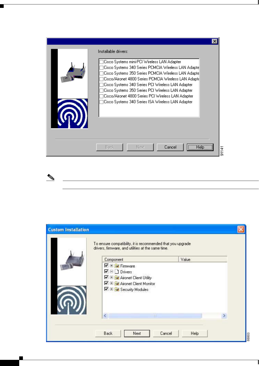
3-14
Cisco Aironet Wireless LAN Client Adapters Installation and Configuration Guide for Windows OL-1394-06
Chapter 3 Installing the Client Adapter
Installing or Upgrading the Client Adapter Software
Figure 3-4 Installable Drivers Screen
Step 17 Select the driver that corresponds to your client adapter type and click Next.
Note You must select a driver even if one is not being installed.
Step 18 If you selected an express installation, go to Step 20. If you selected a custom installation, the Custom
Installation screen appears (see Figure 3-5).
Figure 3-5 Custom Installation Screen

3-15
Cisco Aironet Wireless LAN Client Adapters Installation and Configuration Guide for Windows
OL-1394-06
Chapter 3 Installing the Client Adapter Installing or Upgrading the Client Adapter Software
Step 19 Follow the steps below to make selections on this screen.
a. Make sure a check mark appears beside every software component that you want to install. For every
component that is checked, the Install Wizard will install its version of that component. Every
component that is not checked will remain as it is on your system.
Note Click the + sign beside the Security Modules option to reveal the available security
components.
Note Some components are dependent on others. Therefore, when you select or deselect these
components, the settings of other components may change. A dependency notice appears
when this occurs.
b. Click the + sign beside each component to view additional parameters. The current value of each
parameter appears in the Value field.
c. To change the value of any parameter, click its current value in the Value field. A screen appears that
lets you change the existing value.
d. Enter or select a new value and click OK.Table 3-2 describes each component and its parameters
and lists any default value.

3-16
Cisco Aironet Wireless LAN Client Adapters Installation and Configuration Guide for Windows OL-1394-06
Chapter 3 Installing the Client Adapter
Installing or Upgrading the Client Adapter Software
Table 3-2 Software Components and Their Parameters
Component or Parameter Description
Firmware Installs the firmware version included in the Install Wizard file.
Default: Checked
Disable Firmware
Checking The Disable Firmware Checking parameter affects the firmware that
is bundled with the driver, not the firmware that is included in the
Install Wizard. This parameter controls whether the driver (whenever
it loads) installs the firmware with which it is bundled.
Note The driver loads each time you insert a client adapter or
reboot your computer.
Options: Yes or No
Default: Yes
Disable Firmware Checking Description
Yes Prevents the driver from installing the
firmware with which it is bundled,
enabling the client adapter to retain its
current firmware version.
No Causes the driver to install the firmware
with which it is bundled if that firmware is
newer than the firmware that is currently
installed in the client adapter.
Note This parameter is functionally equivalent to the
Automatically Load New Firmware When NDIS Driver Is
Updated parameter on the ACU Preferences screen. The
parameter that is set last is the one that governs how the driver
behaves. Refer to the “Preventing the Driver from Upgrading
the Firmware” section on page 9-10 for additional
information.
Note The Disable Firmware Checking parameter is available in
Install Wizard version 1.1 or greater.
Drivers Installs the driver version included in the Install Wizard file.
Default: Checked
Aironet Client Utility Installs the ACU version included in the Install Wizard file.
Default: Checked
Installation Path Determines the path where the ACU software will be installed. You
can change the default by entering a new path.
Default: C:\Program Files\Cisco Systems\Aironet Client Utility
Program Folder Determines the program folder where the ACU software will be
installed. You can change the default by entering a new folder name.
Default: Cisco Systems

3-17
Cisco Aironet Wireless LAN Client Adapters Installation and Configuration Guide for Windows
OL-1394-06
Chapter 3 Installing the Client Adapter Installing or Upgrading the Client Adapter Software
Place Icon on Desktop Causes the installation program to add an ACU icon to your
computer’s desktop to provide quick access to the utility.
Options: Yes or No
Default: Yes
Allow Non-Administrator
Users to Save Settings to
the Registry
Enables users without administrative rights to modify profiles in ACU
and save them to the registry.
Options: Yes or No
Default: Yes
Aironet Client Monitor Installs the ACM version included in the Install Wizard file.
Default: Checked
Installation Path Determines the path where the ACM software will be installed. You
can change the default by entering a new path.
Default: C:\Program Files\Cisco Systems\Aironet Client Monitor
Program Folder Determines the program folder where the ACM software will be
installed. You can change the default by entering a new folder name.
Default: Cisco Systems
Auto Start Determines whether ACM starts automatically every time Windows
boots.
Options: Yes or No
Default: Yes
Start After Install Determines whether ACM starts automatically after ACM is installed.
Options: Yes or No
Default: Yes
Table 3-2 Software Components and Their Parameters (continued)
Component or Parameter Description

3-18
Cisco Aironet Wireless LAN Client Adapters Installation and Configuration Guide for Windows OL-1394-06
Chapter 3 Installing the Client Adapter
Installing or Upgrading the Client Adapter Software
Program Feature Overrides Determines which ACM components are enabled. If any components
are not selected now and you later want to use them, you must run this
installation program again and enable them.
Components: See the table below
Options per component: Enable or Disable
Default per component: Enable
Component Description
About Box (Help) Displays the ACM version number and
enables you to access the online help.
Exit Program Closes ACM for all client adapters.
Launch Aironet Client
Utility Activates ACU, if it is installed.
Troubleshooting Activates the troubleshooting utility,
which enables you to identify and resolve
configuration and association problems
with your client adapter.
Preferences Enables you to determine when ACM runs
and to select the options that appear on the
ACM pop-up menu.
Turn Radio On/Off Turns the client adapter’s radio on or off.
Reauthenticate Forces your client adapter to try to
reauthenticate using the username and
password of the current profile.
Select Profile Enables you to select the active profile for
your client adapter.
Auto Profile Selection Causes the client adapter’s driver to
automatically select a profile from the list
of profiles that were set up in ACU to be
included in auto profile selection.
Other Configuration
Application Enables an application other than ACU to
configure the client adapter.
Show Connection Status Provides information on the current status
of your client adapter.
Menu Options (Defaults) Determines which options are displayed on the ACM pop-up menu.
Menu options: About Box (Help), Exit Program, Launch Aironet
Client Utility, Troubleshooting, Turn Radio On/Off,
Reauthenticate, Select Profile, Show Connection
Status
Options per menu option: Show or Hide
Default per menu option: Show
Table 3-2 Software Components and Their Parameters (continued)
Component or Parameter Description

3-19
Cisco Aironet Wireless LAN Client Adapters Installation and Configuration Guide for Windows
OL-1394-06
Chapter 3 Installing the Client Adapter Installing or Upgrading the Client Adapter Software
e. When you are finished making selections, click Next.
Security Modules
LEAP Installs the LEAP supplicant version included in the Install Wizard
file. Installing the LEAP supplicant enables you to create a profile in
ACU that uses LEAP authentication. If this option is not selected now
and you later want to create a profile that uses LEAP, you must run
this installation program again and select this option.
Default: Checked
Note Refer to Chapter 5 for information on enabling LEAP.
Allow Saved LEAP
User Name and
Password
Enables you to create a profile in ACU that uses a saved (rather than
temporary) username and password for LEAP authentication. When
such a profile is used, the saved username and password are used to
start the LEAP authentication process, and you are not prompted to
enter them.
Options: Yes or No
Default: Yes
EAP-SIM Installs the EAP-SIM supplicant version included in the Install
Wizard file. Installing the EAP-SIM supplicant enables the client to
support EAP-SIM authentication. If this option is not selected now
and you later want to use EAP-SIM, you must run this installation
program again and select this option.
Default: Unchecked
Note The Microsoft 802.1X supplicant does not support EAP-SIM
authentication on Windows NT; therefore, EAP-SIM cannot
be enabled for this operating system.
Note If you installed the new EAP-SIM supplicant from the ftpeng
FTP server, make sure the EAP-SIM option is not selected.
Otherwise, the EAP-SIM supplicant included in the Install
Wizard file overwrites the new supplicant’s settings.
PEAP Installs the PEAP supplicant version included in the Install Wizard
file. Installing the PEAP supplicant enables the client to support
PEAP authentication. If this option is not selected now and you later
want to use PEAP, you must run this installation program again and
select this option.
Default: Unchecked
Note The Microsoft 802.1X supplicant does not support Cisco
PEAP authentication on Windows NT; therefore, Cisco PEAP
cannot be enabled for this operating system.
Table 3-2 Software Components and Their Parameters (continued)
Component or Parameter Description
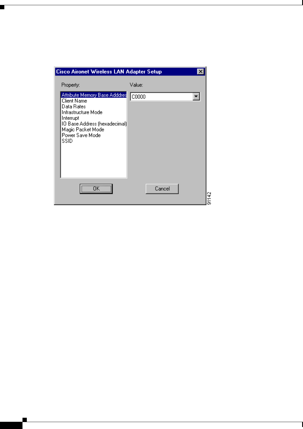
3-20
Cisco Aironet Wireless LAN Client Adapters Installation and Configuration Guide for Windows OL-1394-06
Chapter 3 Installing the Client Adapter
Installing or Upgrading the Client Adapter Software
Step 20 The wizard starts to copy files, and the Cisco Aironet Wireless LAN Adapter Setup screen appears (see
Figure 3-6).
Figure 3-6 Cisco Aironet Wireless LAN Adapter Setup Screen
Step 21 If you are installing a PC or LM card, select Interrupt in the Property list and an unused interrupt (from
Step 9) in the Value field and click OK. If you are installing a PCI or mini PCI card, click OK.
Step 22 Messages appear as binding configurations are stored. Then the Microsoft TCP/IP Properties screen
appears (see Figure 3-7).
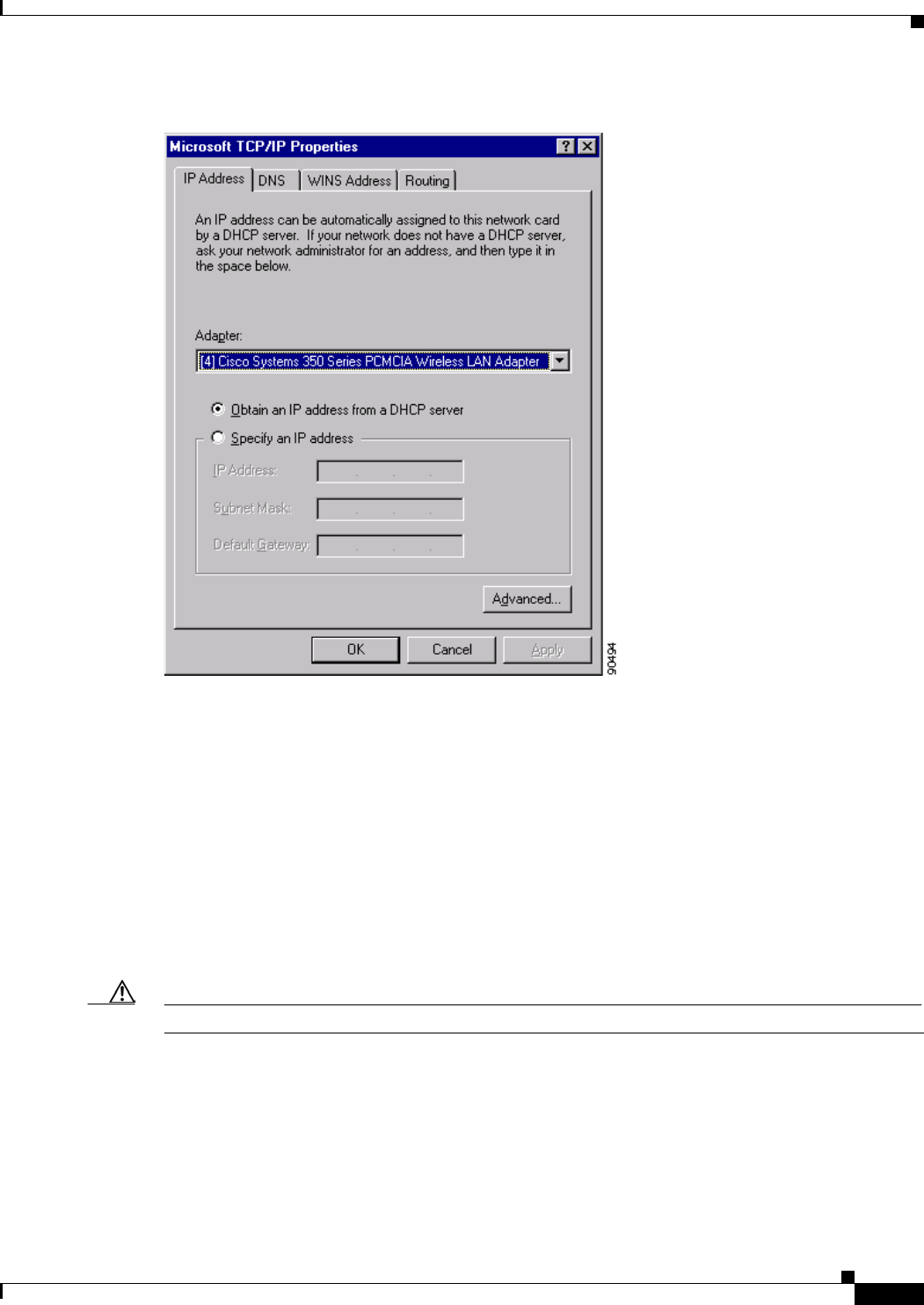
3-21
Cisco Aironet Wireless LAN Client Adapters Installation and Configuration Guide for Windows
OL-1394-06
Chapter 3 Installing the Client Adapter Installing or Upgrading the Client Adapter Software
Figure 3-7 Microsoft TCP/IP Properties Screen
Step 23 On the IP Address tab, find and select the client adapter that you are installing under Adapter.
Step 24 Perform one of the following:
•If your computer is connected to a DHCP server, select Obtain an IP address from a DHCP server.
When asked if you want to enable DHCP, click Yes and OK.
•If your computer is not connected to a DHCP server and you plan to use TCP/IP, select Specify an
IP address and enter the IP address, subnet mask, and default gateway address of your computer
(which can be obtained from your system administrator). Click OK.
The installation process begins, and you are notified as each component is installed.
Step 25 Windows NT must be rebooted in order for your changes to take effect. Click Yes when a message
appears asking if you wish to reboot now.
Caution To prevent unpredictable results, Cisco recommends that you click Yes to reboot your computer now.

3-22
Cisco Aironet Wireless LAN Client Adapters Installation and Configuration Guide for Windows OL-1394-06
Chapter 3 Installing the Client Adapter
Verifying Installation
Step 26 If you want to install a second client adapter, allow your computer to completely reboot; then repeat the
steps in this section for the second adapter.
Note In Step 13, find the Install Wizard files using Windows Explorer. Then double-click the
Setup.exe file.
Step 27 Go to the “Verifying Installation” section below to determine if the installation was successful. After you
verify installation, go to Chapter 4 if you want to create profiles for your client adapter.
Verifying Installation
To verify that you have properly installed the client adapter software, check the client adapter’s LEDs.
If the installation was successful, the client adapter’s green LED blinks.
Note If your installation was unsuccessful or you experienced problems during or after installation, refer to
Chapter 10 for troubleshooting information.
Now that your client adapter is properly installed, you are ready to go to Chapter 4 to create profiles for
your client adapter, unless you are running Windows XP or have more than one client adapter installed.
•If you are running Windows XP, go to the “Deciding How to Configure Your Client Adapter
(Windows XP Only)” section below.
•If you have more than one client adapter installed, go to the “Selecting Among Several Installed
Client Adapters” section on page 3-24.
Deciding How to Configure Your Client Adapter
(Windows XP Only)
Windows XP is the only operating system that enables you to configure your client adapter without using
ACU. Therefore, if your computer is running Windows XP, you must decide whether to configure your
client adapter through Windows XP or ACU. To help you with your decision, Table 3-3 compares the
Windows XP and ACU client adapter features.
Table 3-3 Comparison of Windows XP and ACU Client Adapter Features
Feature Windows XP ACU
Configuration parameters Limited Extensive
Capabilities
Create profiles No Yes
Upgrade radio firmware No Yes
Restart client adapter without
rebooting or ejecting card No Yes
Turn radio on or off No Yes

3-23
Cisco Aironet Wireless LAN Client Adapters Installation and Configuration Guide for Windows
OL-1394-06
Chapter 3 Installing the Client Adapter Deciding How to Configure Your Client Adapter (Windows XP Only)
Perform one of the following:
•If you are planning to configure your client adapter through ACU instead of through Windows XP,
follow the steps below:
a. Double-click My Computer,Control Panel, and Network Connections.
b. Right-click Wireless Network Connection and click Properties.
c. Select the Wireless Networks tab and uncheck the Use Windows to configure my wireless
network settings check box.
d. Select the Authentication tab.
Note In Service Pack 1 for Windows XP, the Authentication tab has moved from its previous
location. To access it, click the Wireless Networks tab, select the network that you are
configuring in the Preferred network list, and click Properties.
e. Uncheck the Enable network access control using IEEE 802.1X check box.
f. Follow the instructions in Chapter 4 and Chapter 5 to configure your client adapter through
ACU.
•If you are planning to configure your client adapter through Windows XP instead of through ACU,
go to Appendix E and follow the instructions there.
•If you are planning to configure your client adapter through Windows XP but you want to use ACU’s
diagnostic tools, go to Appendix E to configure the adapter through Windows XP; then follow the
instructions in Chapter 7 to use ACU’s diagnostic tools.
Security
Static WEP Yes Yes
LEAP authentication with dynamic
WEP No Yes
Host-based EAP authentication with
static or dynamic WEP Yes Yes
Diagnostics
Status screen Limited Extensive
Statistics screen (transmit & receive) No Yes
Site survey tool No Yes
RF link test tool No Yes
Link status meter (graphical display) No Yes
Table 3-3 Comparison of Windows XP and ACU Client Adapter Features (continued)
Feature Windows XP ACU
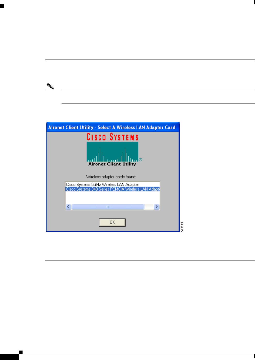
3-24
Cisco Aironet Wireless LAN Client Adapters Installation and Configuration Guide for Windows OL-1394-06
Chapter 3 Installing the Client Adapter
Selecting Among Several Installed Client Adapters
Selecting Among Several Installed Client Adapters
If more than one client adapter is installed in your computer, follow the instructions below to specify the
one for which you want to set up profiles in ACU.
Step 1 Double-click the Aironet Client Utility (ACU) icon on your desktop or double-click My Computer >
Control Panel > Aironet Client Utility to open ACU. The Select A Wireless LAN Adapter Card screen
appears (see Figure 3-8).
Note The Select A Wireless LAN Adapter Card screen appears when you start ACU if more than one
card is inserted in your computer or no cards are inserted but more than one card is installed.
Figure 3-8 Select A Wireless LAN Adapter Card Screen
Step 2 Select the card you wish to configure from the list of available cards and click OK.
Step 3 Go to Chapter 4 to create profiles for this card.

CHAPTER
4-1
Cisco Aironet Wireless LAN Client Adapters Installation and Configuration Guide for Windows
OL-1394-06
4
Using the Profile Manager
This chapter explains how to use ACU’s profile manager feature to create and manage profiles for your
client adapter.
The following topics are covered in this chapter:
•Overview of Profile Manager, page 4-2
•Opening Profile Manager, page 4-2
•Creating a New Profile, page 4-3
•Including a Profile in Auto Profile Selection, page 4-4
•Selecting the Active Profile, page 4-6
•Modifying a Profile, page 4-7
•Importing and Exporting Profiles, page 4-9
•Granting or Denying Access to Non-Administrative Users, page 4-10
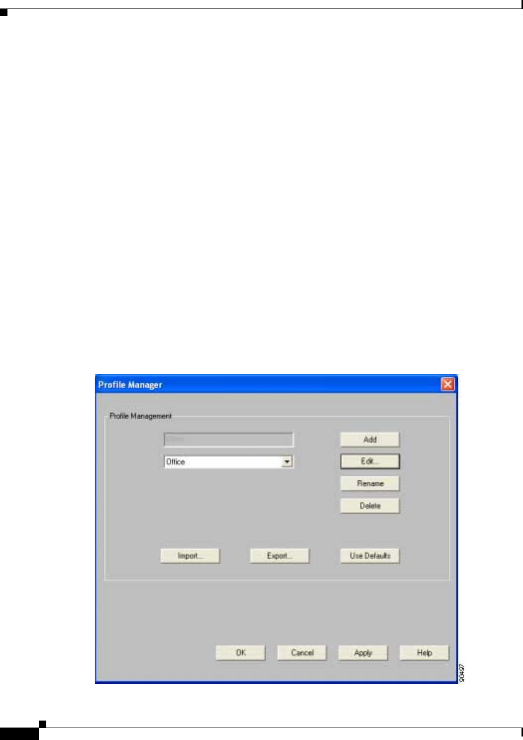
4-2
Cisco Aironet Wireless LAN Client Adapters Installation and Configuration Guide for Windows OL-1394-06
Chapter 4 Using the Profile Manager
Overview of Profile Manager
Overview of Profile Manager
ACU’s profile manager feature allows you to create and manage up to 16 profiles (or saved
configurations) for your client adapter. These profiles enable you to use your client adapter in different
locations, each of which requires different configuration settings. For example, you may want to set up
profiles for using your client adapter at the office, at home, and in public areas such as airports. Once
the profiles are created, you can easily switch between them without having to reconfigure your client
adapter each time you enter a new location.
Profiles are stored in the part of the registry reserved for the client adapter driver and, therefore, are tied
to radio type. Consequently, if you set up profiles for a 340 series PC card and later upgrade to a 350
series PC card, all of the profiles will be lost. Similarly, all profiles are lost if you uninstall the client
adapter’s software components. To prevent your profiles from becoming lost, Cisco recommends that
you back up your profiles using the profile manager’s import/export feature. See the “Importing and
Exporting Profiles” section on page 4-9 for details.
Opening Profile Manager
To open ACU’s profile manager, double-click the Aironet Client Utility (ACU) icon on your desktop
or double-click My Computer > Control Panel > Aironet Client Utility to open ACU. Then click the
Profile Manager icon or select Profile Manager from the Commands drop-down menu. The Profile
Manager screen appears (see Figure 4-1).
Figure 4-1 Profile Manager Screen

4-3
Cisco Aironet Wireless LAN Client Adapters Installation and Configuration Guide for Windows
OL-1394-06
Chapter 4 Using the Profile Manager Creating a New Profile
Profile manager allows you to perform the following tasks related to the management of profiles:
•Create a new profile, see below
•Include a profile in auto profile selection, page 4-4
•Select the active profile, page 4-6
•Edit a profile, page 4-7
•Set a profile to default values, page 4-8
•Rename a profile, page 4-8
•Delete a profile, page 4-8
•Import a profile, page 4-9
•Export a profile, page 4-9
Follow the instructions on the page indicated for the task you want to perform.
Note If your system administrator used an administrative tool to deactivate certain parameters, these
parameters are disabled on the Profile Manager screen and cannot be selected.
Creating a New Profile
Follow the steps below to create a new profile.
Step 1 Click Add on the Profile Manager screen. A cursor appears in the Profile Management edit box.
Step 2 Enter the name for your new profile (for example, Office, Home, etc.).
Step 3 Press Enter. The Properties screens appear with the name of your new profile in parentheses.
Step 4 Perform one of the following:
•If you want this profile to use the default values, click OK. The profile is added to the list of profiles
on the Profile Manager screen.
•If you want to change any of the configuration parameter settings, follow the instructions in
Chapter 5. The profile is added to the list of profiles on the Profile Manager screen.
Step 5 Click OK or Apply to save your profile.
Note The profiles for PC-Cardbus cards are tied to the slot in which the card is inserted. Therefore,
you must always insert your PC-Cardbus card into the same slot, create profiles for both slots,
or export the profiles from one slot and import them for the other slot.
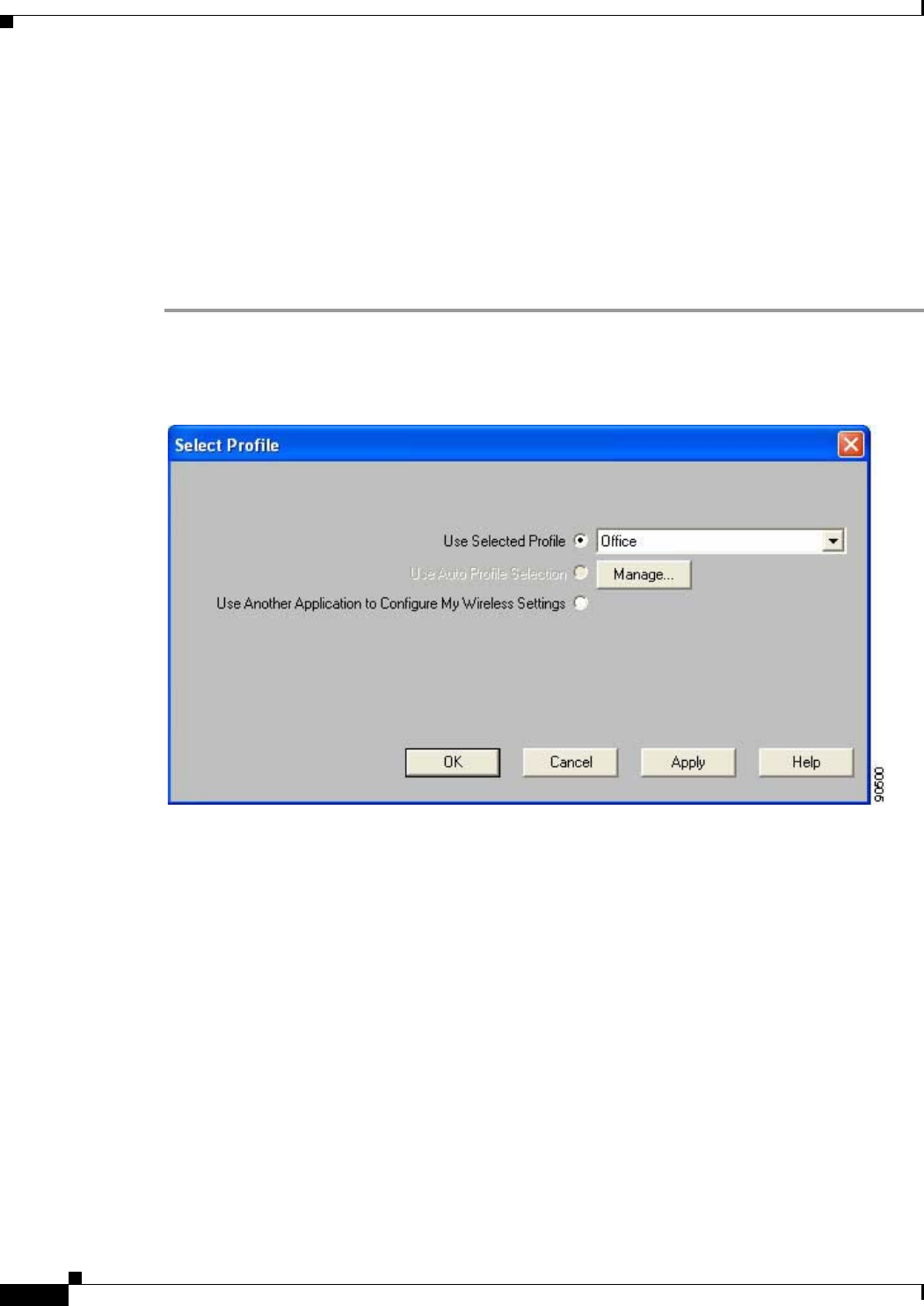
4-4
Cisco Aironet Wireless LAN Client Adapters Installation and Configuration Guide for Windows OL-1394-06
Chapter 4 Using the Profile Manager
Including a Profile in Auto Profile Selection
Including a Profile in Auto Profile Selection
After you have created profiles for your client adapter, you can choose to include them in the profile
manager’s auto profile selection feature. Then when auto profile selection is enabled, the client adapter
automatically selects a profile from the list of profiles that were included in auto profile selection and
uses it to establish a connection to the network.
Follow the steps below to include any of your profiles in auto profile selection and to establish the order
in which the profiles will be selected for use.
Step 1 Open ACU; click the Select Profile icon or select Select Profile from the Commands drop-down menu.
The Select Profile screen appears (see Figure 4-2).
Figure 4-2 Select Profile Screen
Step 2 Click the Manage button next to the Use Auto Profile Selection option. The Auto Profile Selection
Management screen appears (see Figure 4-3).
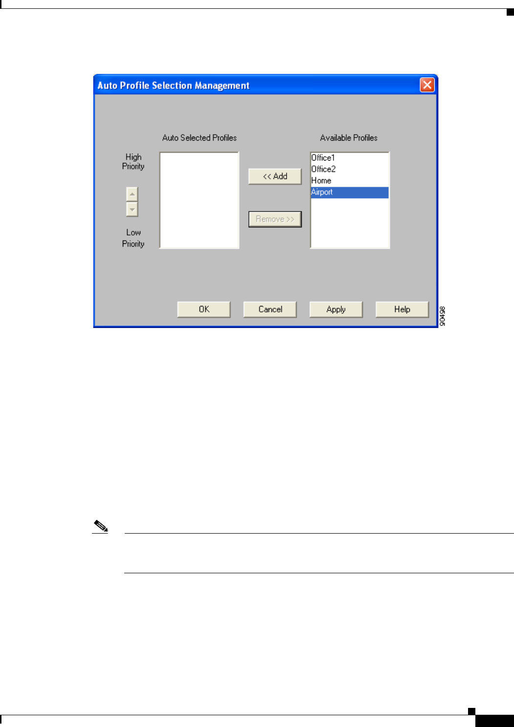
4-5
Cisco Aironet Wireless LAN Client Adapters Installation and Configuration Guide for Windows
OL-1394-06
Chapter 4 Using the Profile Manager Including a Profile in Auto Profile Selection
Figure 4-3 Auto Profile Selection Management Screen
Step 3 All the profiles that you created are listed in the Available Profiles box. Highlight each one that you want
to include in auto profile selection and click the Add button. The profiles move to the Auto Selected
Profiles box.
The following rules apply to auto profile selection:
•You must include at least two profiles in the Auto Selected Profiles Box.
•The profiles must specify an SSID; otherwise, they cannot be selected in the Available Profiles
box.
•Profiles cannot specify multiple SSIDs; otherwise, they cannot be selected in the Available
Profiles box.
•Each profile that is included in auto profile selection must have a unique SSID. For example,
if Profile A and Profile B both have “ABCD” as their SSID, only Profile A or Profile B can be
included in auto profile selection.
Note If you ever want to remove a profile from auto profile selection, highlight the profile in the Auto
Selected Profiles box and click the Remove button. The profile moves to the Available Profiles
box.

4-6
Cisco Aironet Wireless LAN Client Adapters Installation and Configuration Guide for Windows OL-1394-06
Chapter 4 Using the Profile Manager
Selecting the Active Profile
Step 4 The first profile in the Auto Selected Profiles box has the highest priority while the last profile has the
lowest priority. To change the order (and priority) of your auto-selectable profiles, highlight the profile
that you want to move and click the High Priority or Low Priority arrow to move the profile up or
down, respectively.
When auto profile selection is enabled, the client adapter scans for an available network. The profile with
the highest priority and the same SSID as one of the found networks is the one that is used to connect to
the network. If the connection fails, the client adapter tries the next highest priority profile that matches
the SSID and so on.
Step 5 Click OK to save your changes.
Selecting the Active Profile
Follow the steps below to specify the profile that the client adapter is to use.
Note Because EAP-TLS, PEAP, and EAP-SIM authentication are enabled in the operating system and not in
ACU, you cannot switch between these authentication types simply by switching profiles in ACU. You
can create a profile in ACU that uses host-based EAP, but you must enable the specific authentication
type in Windows (provided Windows is using the Microsoft 802.1X supplicant). In addition, Windows
can be set for only one authentication type at a time; therefore, if you have more than one profile in ACU
that uses host-based EAP and you want to use another authentication type, you must change
authentication types in Windows after switching profiles in ACU.
Note You can use ACM instead of ACU’s Profile Manager to select the active profile. Refer to Chapter 8 for
instructions.
Step 1 Open ACU; click the Select Profile icon or select Select Profile from the Commands drop-down menu.
The Select Profile screen appears (see Figure 4-2).
Step 2 Select one of the following options:
•Use Selected Profile—This option enables you to select one profile for the client adapter to use. If
you choose this option, you also must select the desired profile from the drop-down box.
If the client adapter cannot associate to an access point or loses association while using the selected
profile, the adapter does not attempt to associate using another profile. To associate, you must select
a different profile or select Use Auto Profile Selection.
Note If no profiles have been set for your client adapter, the Use Selected Profile drop-down box
is disabled but displays “Driver Advanced Tab Settings.”

4-7
Cisco Aironet Wireless LAN Client Adapters Installation and Configuration Guide for Windows
OL-1394-06
Chapter 4 Using the Profile Manager Modifying a Profile
•Use Auto Profile Selection—This option causes the client adapter’s driver to automatically select
a profile from the list of profiles that were set up to be included in auto profile selection.
If the client adapter loses association for more than 10 seconds (or for more than the time specified
by the LEAP authentication timeout value on the LEAP Settings screen if LEAP is enabled), the
driver switches automatically to another profile that is included in auto profile selection. The adapter
will not switch profiles as long as it remains associated or reassociates within 10 seconds (or within
the time specified by the LEAP authentication timeout value). To force the client adapter to associate
to a different access point, you must select a new profile using the Use Selected Profile option.
Note This option is available only if two or more profiles are included in auto profile selection.
Note Login scripts are not reliable if you use auto profile selection with LEAP. If you LEAP
authenticate and achieve full network connectivity before or at the same time as you log into
the computer, the login scripts will run. However, if you LEAP authenticate and achieve full
network connectivity after you log into the computer, the login scripts will not run.
•Use Another Application to Configure My Wireless Settings—This option enables an application
other than ACU to configure the client adapter. Examples of such applications include Windows XP
and Boingo.
Note You must select this option if you are configuring your card through Windows XP but want
to use ACU’s diagnostic tools. Refer to Appendix E for information on configuring your
client adapter through Windows XP.
Step 3 Click OK or Apply to save your selection. The client adapter starts using a profile based on the option
selected above.
Modifying a Profile
This section provides instructions for modifying an existing profile. Follow the steps in the
corresponding section below to edit, set to default values, rename, or delete a profile.
Editing a Profile
Step 1 Open ACU; click the Profile Manager icon or select Profile Manager from the Commands drop-down
menu. The Profile Manager screen appears (see Figure 4-1).
Step 2 From the Profile Management drop-down box, select the profile that you want to edit.
Step 3 Click Edit. The Properties screens appear with the name of the profile in parentheses.
Step 4 Follow the instructions in Chapter 5 to change any of the configuration parameters for this profile.
Step 5 Click OK or Apply to save your configuration changes.

4-8
Cisco Aironet Wireless LAN Client Adapters Installation and Configuration Guide for Windows OL-1394-06
Chapter 4 Using the Profile Manager
Modifying a Profile
Setting a Profile to Default Values
Step 1 Open ACU; click the Profile Manager icon or select Profile Manager from the Commands drop-down
menu. The Profile Manager screen appears (see Figure 4-1).
Step 2 From the Profile Management drop-down box, select the profile that you want to set to default values.
Step 3 Click Use Defaults.
Step 4 When prompted, click Yes to confirm your decision.
Step 5 Click OK or Apply to save your change. The profile is saved with default values.
Renaming a Profile
Step 1 Open ACU; click the Profile Manager icon or select Profile Manager from the Commands drop-down
menu. The Profile Manager screen appears (see Figure 4-1).
Step 2 From the Profile Management drop-down box, select the profile that you want to rename.
Step 3 Click Rename. The Profile Management edit box becomes enabled.
Step 4 Enter a new name for the profile.
Step 5 Click OK or Apply to save your change. The profile is renamed and added to the list of profiles.
Deleting a Profile
Step 1 Open ACU; click the Profile Manager icon or select Profile Manager from the Commands drop-down
menu. The Profile Manager screen appears (see Figure 4-1).
Step 2 From the Profile Management drop-down box, select the profile that you want to delete.
Step 3 Click Delete.
Step 4 When prompted, click Yes to confirm your decision.
Step 5 Click OK or Apply to save your change. The profile is deleted.

4-9
Cisco Aironet Wireless LAN Client Adapters Installation and Configuration Guide for Windows
OL-1394-06
Chapter 4 Using the Profile Manager Importing and Exporting Profiles
Importing and Exporting Profiles
This section provides instructions for importing and exporting profiles. You may want to use the
import/export feature for the following reasons:
•To back up profiles before changing client adapter types or uninstalling client adapter software
components
•To export profiles for a PC-Cardbus card in one Cardbus slot and import them for use with a second
Cardbus slot
•To set up your computer with a profile from another computer
•To export one of your profiles and use it to set up additional computers
Follow the steps in the corresponding section below to import or export profiles.
Importing a Profile
Step 1 If the profile that you want to import is on a floppy disk, insert the disk into your computer’s floppy drive.
Step 2 Open ACU; click the Profile Manager icon or select Profile Manager from the Commands drop-down
menu. The Profile Manager screen appears (see Figure 4-1).
Step 3 Click Import. The Import Profile screen appears.
Step 4 Find the directory where the profile is located.
Step 5 Click the profile so it appears in the File name box at the bottom of the Import Profile screen.
Step 6 Click Open. The imported profile appears in the list of profiles on the Profile Manager screen.
Exporting a Profile
Step 1 Insert a blank floppy disk into your computer’s floppy drive, if you wish to export a profile to a floppy
disk.
Step 2 Open ACU; click the Profile Manager icon or select Profile Manager from the Commands drop-down
menu. The Profile Manager screen appears (see Figure 4-1).
Step 3 From the Profile Management drop-down box, select the profile that you want to export.
Step 4 Click Export. The Save Profile As screen appears. The default filename is ProfileName.pro, where
ProfileName is the name of the selected profile, and the default directory is the directory in which ACU
is installed.
Step 5 If you want to change the profile name, enter a new name in the File name edit box.
Step 6 Select a different directory (for example, your computer’s floppy disk drive or a location on the network)
from the Save in drop-down box.
Step 7 Click Save. The profile is exported to the specified location.
Step 8 Follow the instructions in the “Importing a Profile” section to import the profile on another computer.
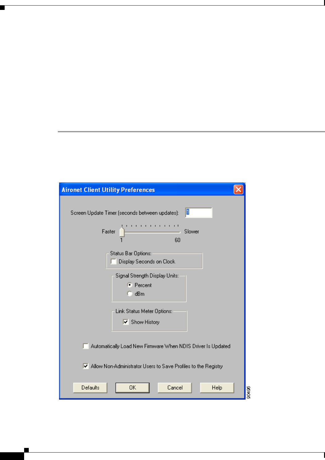
4-10
Cisco Aironet Wireless LAN Client Adapters Installation and Configuration Guide for Windows OL-1394-06
Chapter 4 Using the Profile Manager
Granting or Denying Access to Non-Administrative Users
Granting or Denying Access to Non-Administrative Users
If you used the Install Wizard to perform a custom installation, you were able to specify the value of the
Allow Non-Administrator Users to Save Settings to the Registry parameter. When this parameter is set
to Yes, it enables users without administrative rights to modify profiles in ACU and save them to the
registry on computers running Windows NT, 2000, or XP. (This option is not available for Windows 98,
98 SE, and Me because these versions of Windows do not support different classes of users.) When this
parameter is set to No, access to non-administrative users is denied.
ACU has a similar parameter that you can use to change the selection you made during installation,
provided you have administrative rights. Follow the steps below if you want to change the current setting
of this parameter.
Step 1 Open ACU.
Step 2 Click the Preferences icon or select Preferences from the Options drop-down menu. The Aironet Client
Utility Preferences screen appears (see Figure 4-4).
Figure 4-4 Aironet Client Utility Preferences Screen

4-11
Cisco Aironet Wireless LAN Client Adapters Installation and Configuration Guide for Windows
OL-1394-06
Chapter 4 Using the Profile Manager Granting or Denying Access to Non-Administrative Users
Step 3 Perform one of the following:
•Check the Allow Non-Administrator Users to Save Profiles to the Registry check box if you want
to allow regular-class users to modify and save profiles.
•Uncheck the Allow Non-Administrator Users to Save Profiles to the Registry check box if you
want to prevent regular-class users from modifying and saving profiles.
Step 4 Click OK to save your changes.

4-12
Cisco Aironet Wireless LAN Client Adapters Installation and Configuration Guide for Windows OL-1394-06
Chapter 4 Using the Profile Manager
Granting or Denying Access to Non-Administrative Users

CHAPTER
5-1
Cisco Aironet Wireless LAN Client Adapters Installation and Configuration Guide for Windows
OL-1394-06
5
Configuring the Client Adapter
This chapter explains how to set the configuration parameters for a specific profile.
The following topics are covered in this chapter:
•Overview, page 5-2
•Setting System Parameters, page 5-3
•Setting RF Network Parameters, page 5-7
•Setting Advanced Infrastructure Parameters, page 5-14
•Setting Advanced Ad Hoc Parameters, page 5-17
•Setting Network Security Parameters, page 5-20

5-2
Cisco Aironet Wireless LAN Client Adapters Installation and Configuration Guide for Windows OL-1394-06
Chapter 5 Configuring the Client Adapter
Overview
Overview
When you choose to create a new profile or edit an existing profile on the Profile Manager screen, the
Properties screens appear with the name of your profile in parentheses. These screens enable you to set
the configuration parameters for that profile.
Note If you do not change any of the configuration parameters, the default values are used.
Note If you are planning to set parameters on more than one of the Properties screens, wait until you are
finished with all of the screens before clicking OK. When you click OK, you are returned to the Profile
Manager screen.
Each of the Properties screens (listed below) contains parameters that affect a specific aspect of the client
adapter:
•System Parameters—Prepares the client adapter for use in a wireless network
•RF Network—Controls how the client adapter transmits and receives data
•Advanced (Infrastructure)—Controls how the client adapter operates within an infrastructure
network
•Advanced (Ad Hoc)—Controls how the client adapter operates within an ad hoc (peer-to-peer)
network
•Network Security—Controls how a client adapter associates to an access point, authenticates to the
wireless network, and encrypts and decrypts data
Table 5-1 enables you to quickly locate the instructions for setting each Properties screen’s parameters.
Table 5-1 Locating Configuration Instructions
Parameter Category Page Number
System page 5-3
RF network page 5-7
Advanced infrastructure page 5-14
Advanced ad hoc page 5-17
Network security page 5-20
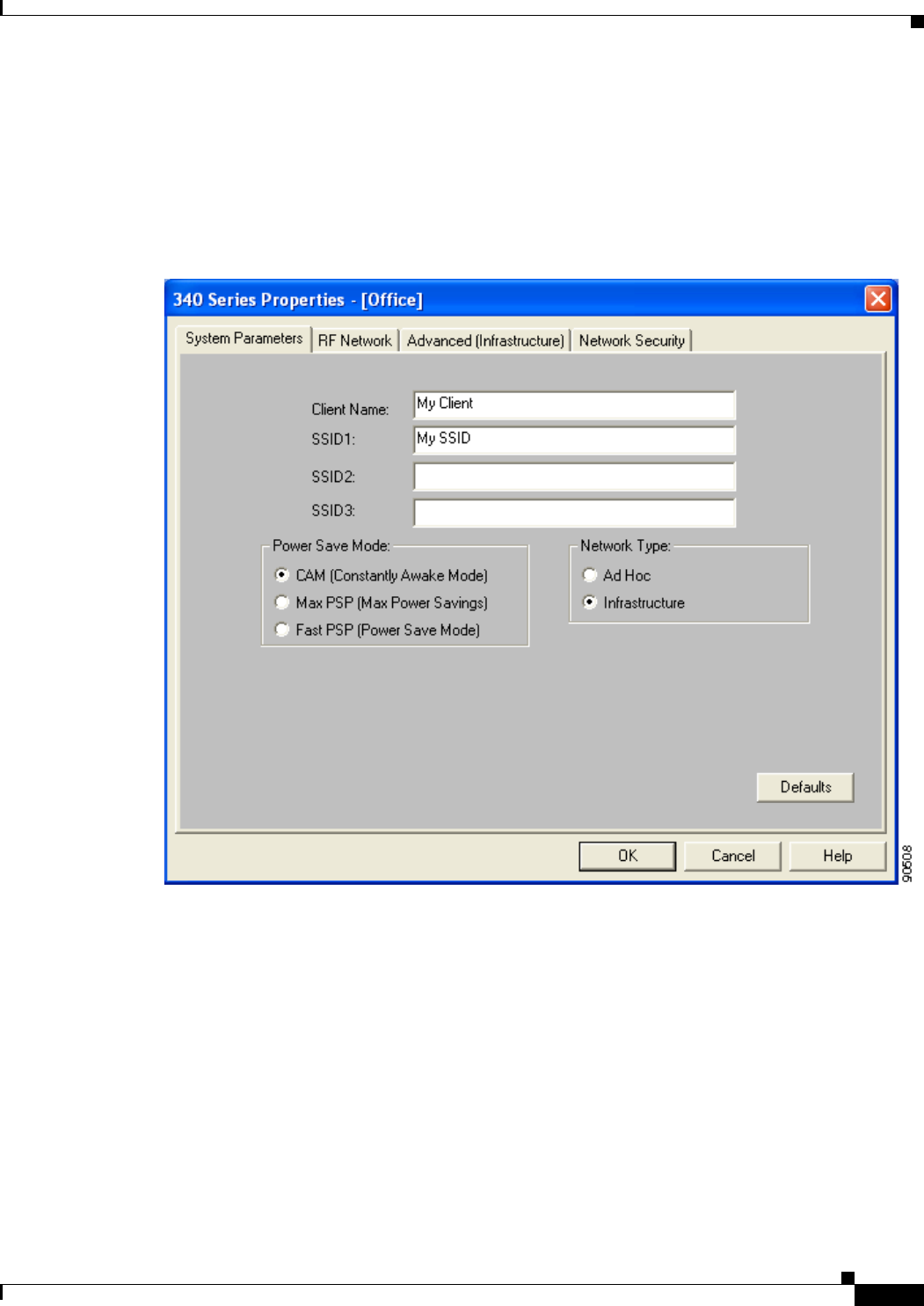
5-3
Cisco Aironet Wireless LAN Client Adapters Installation and Configuration Guide for Windows
OL-1394-06
Chapter 5 Configuring the Client Adapter Setting System Parameters
Setting System Parameters
The System Parameters screen (see Figure 5-1) enables you to set parameters that prepare the client
adapter for use in a wireless network. This screen appears after you create and save a new profile or click
Edit on the Profile Manager screen.
Figure 5-1 System Parameters Screen
Table 5-2 lists and describes the client adapter’s system parameters. Follow the instructions in the table
to change any parameters.

5-4
Cisco Aironet Wireless LAN Client Adapters Installation and Configuration Guide for Windows OL-1394-06
Chapter 5 Configuring the Client Adapter
Setting System Parameters
Table 5-2 System Parameters
Parameter Description
Client Name A logical name for your workstation. It allows an administrator to
determine which devices are connected to the access point without
having to memorize every MAC address. This name is included in the
access point’s list of connected devices.
Range: You can key in up to 16 ASCII characters
Default: A blank field
Note Each computer on the network should have a unique client
name.
SSID1 The service set identifier (SSID) identifies the specific wireless
network that you want to access.
Range: You can key in up to 32 ASCII characters (case sensitive)
Default: A blank field
Note If you leave this parameter blank, your client adapter can
associate to any access point on the network that is configured
to allow broadcast SSIDs (see the AP Radio Hardware page in
the access point management system). If the access point with
which the client adapter is to communicate is not configured to
allow broadcast SSIDs, the value of this parameter must match
the SSID of the access point. Otherwise, the client adapter is
unable to access the network.
SSID2 An optional SSID that identifies a second distinct network and enables
you to roam to that network without having to reconfigure your client
adapter.
Range: You can key in up to 32 ASCII characters (case sensitive)
Default: A blank field
Note If a profile specifies more than one SSID, it cannot be included
in auto profile selection.
Note This field is unavailable for any profiles that are included in
auto profile selection.
SSID3 An optional SSID that identifies a third distinct network and enables
you to roam to that network without having to reconfigure your client
adapter.
Range: You can key in up to 32 ASCII characters (case sensitive)
Default: A blank field
Note If a profile specifies more than one SSID, it cannot be included
in auto profile selection.
Note This field is unavailable for any profiles that are included in
auto profile selection.

5-5
Cisco Aironet Wireless LAN Client Adapters Installation and Configuration Guide for Windows
OL-1394-06
Chapter 5 Configuring the Client Adapter Setting System Parameters
Power Save Mode Sets your client adapter to its optimum power consumption setting.
Options: CAM, Max PSP, or Fast PSP
Default: CAM (Constantly Awake Mode)
Power Save Mode Description
CAM (Constantly Awake
Mode) Keeps the client adapter powered up
continuously so there is little lag in
message response time.
Consumes the most power but offers the
highest throughput. Is recommended for
desktop computers and devices that use
AC power.
Max PSP (Max Power
Savings) Causes the access point to buffer incoming
messages for the client adapter, which
wakes up periodically and polls the access
point to see if any buffered messages are
waiting for it. The adapter can request
each message and then go back to sleep.
Conserves the most power but offers the
lowest throughput. Is recommended for
devices for which power consumption is
the ultimate concern (such as small
battery-powered devices).
Note When you set Max PSP mode and
close ACU, the following message
appears the next time you open
ACU: “Maximum Power Save
Mode will be temporarily disabled
while you are running this
application.” While ACU is open,
Fast PSP mode is active. When
you close ACU, the card returns to
Max PSP mode.
Fast PSP (Power Save
Mode) Switches between PSP mode and CAM
mode, depending on network traffic. This
mode switches to CAM when retrieving a
large number of packets and switches back
to PSP after the packets have been
retrieved.
Is recommended when power consumption
is a concern but you need greater
throughput than that allowed by Max PSP.
Table 5-2 System Parameters (continued)
Parameter Description

5-6
Cisco Aironet Wireless LAN Client Adapters Installation and Configuration Guide for Windows OL-1394-06
Chapter 5 Configuring the Client Adapter
Setting System Parameters
Go to the next section to set additional parameters or click OK to return to the Profile Manager screen.
On the Profile Manager screen, click OK or Apply to save your changes.
Network Type Specifies the type of network in which your client adapter is installed.
Options: Ad Hoc or Infrastructure
Default: Infrastructure
Network Type Description
Ad Hoc Often referred to as peer to peer. Indicates
that your wireless network consists of a
few wireless devices that are not
connected to a wired Ethernet network
through an access point. For example, an
ad hoc network can be set up between
computers in a conference room so users
can share information in a meeting.
Infrastructure Indicates that your wireless network is
connected to a wired Ethernet network
through an access point.
Table 5-2 System Parameters (continued)
Parameter Description
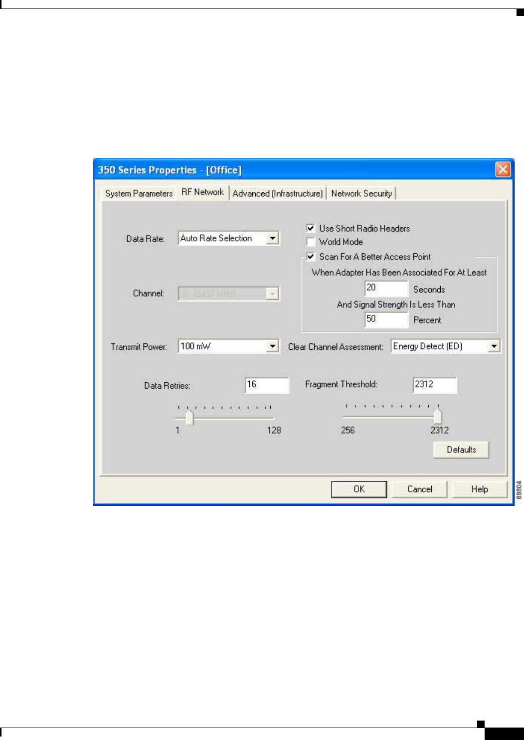
5-7
Cisco Aironet Wireless LAN Client Adapters Installation and Configuration Guide for Windows
OL-1394-06
Chapter 5 Configuring the Client Adapter Setting RF Network Parameters
Setting RF Network Parameters
The RF Network screen (see Figure 5-2) enables you to set parameters that control how and when the
client adapter transmits and receives data. To access this screen, select the RF Network tab from the
Properties screens.
Figure 5-2 RF Network Screen

5-8
Cisco Aironet Wireless LAN Client Adapters Installation and Configuration Guide for Windows OL-1394-06
Chapter 5 Configuring the Client Adapter
Setting RF Network Parameters
Table 5-3 lists and describes the client adapter’s RF network parameters. Follow the instructions in the
table to change any parameters.
Table 5-3 RF Network Parameters
Parameter Description
Data Rate Specifies the rate at which your client adapter should transmit or
receive packets to or from access points (in infrastructure mode) or
other clients (in ad hoc mode).
Auto Rate Selection is recommended for infrastructure mode; setting a
specific data rate is recommended for ad hoc mode.
Options: Auto Rate Selection, 1 Mbps Only, 2 Mbps Only, 5.5 Mbps
Only, or 11 Mbps Only (2.4-GHz client adapters);
Auto Rate Selection, 6 Mbps Only, 9 Mbps Only, 12 Mbps
Only, 18 Mbps Only, 24 Mbps Only, 36 Mbps Only, 48 Mbps
Only, or 54 Mbps Only (5-GHz client adapters)
Default: Auto Rate Selection
Data Rate
Description
2.4-GHz Client
Adapters 5-GHz Client
Adapters
Auto Rate
Selection Auto Rate
Selection Uses the 11-Mbps (for 2.4-GHz client
adapters) or 54-Mbps (for 5-GHz client
adapters) data rate when possible but
drops to lower rates when necessary.
1 Mbps
Only 6 Mbps
Only Offers the greatest range but the lowest
throughput.
2 Mbps
Only and
5.5 Mbps
Only
9 Mbps
Only to 48
Mbps Only
Progressively offers less range but greater
throughput than the 1 Mbps Only (for
2.4-GHz client adapters) or 6 Mbps Only
(for 5-GHz client adapters) option.
11 Mbps
Only 54 Mbps
Only Offers the greatest throughput but the
lowest range.
Note Your client adapter’s data rate must be set to Auto Rate
Selection or must match the data rate of the access point (in
infrastructure mode) or the other clients (in ad hoc mode) with
which it is to communicate. Otherwise, your client adapter may
not be able to associate to them.

5-9
Cisco Aironet Wireless LAN Client Adapters Installation and Configuration Guide for Windows
OL-1394-06
Chapter 5 Configuring the Client Adapter Setting RF Network Parameters
Use Short Radio Headers Checking this check box sets your client adapter to use short radio
headers. However, the adapter can use short radio headers only if the
access point is also configured to support them and is using them. If any
clients associated to an access point are using long headers, then all
clients in that cell must also use long headers, even if both this client
and the access point have short radio headers enabled.
Short radio headers improve throughput performance; long radio
headers ensure compatibility with clients and access points that do not
support short radio headers.
Default: Checked
Note This parameter is available only for 2.4-GHz client adapters.
Note This parameter is referred to as Preambles on the access point
screens.
World Mode Checking this check box enables the client adapter to adopt the
maximum transmit power level and the frequency range of the access
point to which it is associated, provided the access point is also
configured for world mode. This parameter is available only in
infrastructure mode and is designed for users who travel between
countries and want their client adapters to associate to access points in
different regulatory domains.
Default: Unchecked
Note This parameter is available only for 2.4-GHz client adapters.
Note When World Mode is enabled, the client adapter is limited to
the maximum transmit power level allowed by the country of
operation’s regulatory agency.
Scan For A Better Access
Point Checking this check box causes the client to look for a better access
point if the signal strength of its associated access point is less than the
specified value after the specified time and to switch associations if it
finds one.
Example: If the default values of 20 seconds and 50% are used, the
client begins monitoring the strength of the signal received
from its associated access point 20 seconds after becoming
associated. The monitoring continues once per second. If
the client detects a signal strength reading below 50%, it
scans for a better access point.
Range: 5 to 255 seconds; 0 to 75% signal strength
Defaults:Checked, 20 seconds, 50% signal strength
Note The ability to specify the time and signal strength is available
in ACU version 6.1 or greater, which is included in Install
Wizard version 1.1 or greater.
Table 5-3 RF Network Parameters (continued)
Parameter Description

5-10
Cisco Aironet Wireless LAN Client Adapters Installation and Configuration Guide for Windows OL-1394-06
Chapter 5 Configuring the Client Adapter
Setting RF Network Parameters
Channel Specifies the frequency that your client adapter will use as the channel
for communications. These channels conform to the IEEE 802.11
Standard for your regulatory domain.
•In infrastructure mode, this parameter is set automatically and
cannot be changed. The client adapter listens to the entire
spectrum, selects the best access point to associate to, and uses the
same frequency as that access point.
•In ad hoc mode, the channel of the client adapter must be set to
match the channel used by the other clients in the wireless network.
If the client adapter does not find any other ad hoc adapters, this
parameter specifies the channel with which the adapter will start its
cell.
Range: Dependent on client adapter radio and regulatory domain
Example for 2.4-GHz client adapters:
1 to 11 (2412 to 2462 MHz) in North America
Example for 5-GHz client adapters:
36, 40, 44, 48, 52, 56, 60, and 64 (5180, 5200, 5220, 5240,
5260, 5280, 5300, and 5320 MHz) in North America
Default: Dependent on client adapter radio and regulatory domain
Example for 2.4-GHz client adapters:
6 (2437 MHz) in North America
Example for 5-GHz client adapters:
36 (5180 MHz) in North America
Note Refer to Appendix D for a list of channel identifiers, channel
center frequencies, and regulatory domains for each channel.
Table 5-3 RF Network Parameters (continued)
Parameter Description

5-11
Cisco Aironet Wireless LAN Client Adapters Installation and Configuration Guide for Windows
OL-1394-06
Chapter 5 Configuring the Client Adapter Setting RF Network Parameters
Transmit Power Defines the power level at which your client adapter transmits. This
value must not be higher than that allowed by your country’s regulatory
agency (FCC in the U.S., DOC in Canada, ETSI in Europe, MKK in
Japan, etc.).
Options: Dependent on the power table programmed into the client
adapter; see the table below
Default: The maximum power level programmed into the client
adapter and allowed by your country’s regulatory agency
Possible Power Levels Client Adapter Type
30 mW or 1 mW 340 series PC cards
30 mW, 15 mW, 5 mW, or
1 mW 340 series LM cards and PCI cards
100 mW, 50 mW, 30 mW,
20 mW, 5 mW, or 1 mW 350 series client adapters
20 mW, 10 mW, or 5 mW PC-Cardbus card
Note Reducing the transmit power level conserves battery power but
decreases radio range.
Note When World Mode is enabled, the client adapter is limited to
the maximum transmit power level allowed by the country of
operation’s regulatory agency.
Note If you are using an older version of a 340 or 350 series client
adapter, your power level options may be different than those
listed here.
Table 5-3 RF Network Parameters (continued)
Parameter Description

5-12
Cisco Aironet Wireless LAN Client Adapters Installation and Configuration Guide for Windows OL-1394-06
Chapter 5 Configuring the Client Adapter
Setting RF Network Parameters
Clear Channel Assessment Specifies the method that determines whether the channel on which
your client adapter will operate is clear prior to the transmission of
data.
Options: Firmware Default (XXX), Carrier/Correlation (Car/Cor),
Energy Detect (ED), or ED or Car/Cor
Default: Firmware Default (XXX)
Method Description
Firmware Default (XXX) The Clear Channel Assessment (CCA)
mechanism will report that the channel is
busy based on the default value of the
client adapter’s firmware. The firmware’s
CCA default value is shown in
parentheses.
Note The CCA default value for PCM,
LMC, and PCI card firmware is
Car/Cor; the default value for mini
PCI card firmware is ED.
Carrier/Correlation
(Car/Cor) The CCA mechanism will report that the
channel is busy upon detection of a
direct-sequence spread spectrum (DSSS)
signal. This signal may be above or below
the ED threshold.
Energy Detect (ED) The CCA mechanism will report that the
channel is busy upon detection of any
energy above the ED threshold.
ED or Car/Cor The CCA mechanism will report that the
channel is busy upon detection of a DSSS
signal or any energy above the ED
threshold.
Note This parameter is available only for 2.4-GHz client adapters.
Table 5-3 RF Network Parameters (continued)
Parameter Description

5-13
Cisco Aironet Wireless LAN Client Adapters Installation and Configuration Guide for Windows
OL-1394-06
Chapter 5 Configuring the Client Adapter Setting RF Network Parameters
Go to the next section to set additional parameters or click OK to return to the Profile Manager screen.
On the Profile Manager screen, click OK or Apply to save your changes.
Data Retries Defines the number of times a packet is resent if the initial transmission
is unsuccessful.
Range: 1 to 128
Default: 16 (2.4-GHz client adapters) or 32 (5-GHz client adapters)
Note If your network protocol performs its own retries, set this to a
smaller value than the default. This way notification of a “bad”
packet is sent up the protocol stack quickly so the application
can retransmit the packet if necessary.
Fragment Threshold Defines the threshold above which an RF data packet is split up or
fragmented. If one of those fragmented packets experiences
interference during transmission, only that specific packet would need
to be resent.
Throughput is generally lower for fragmented packets because the fixed
packet overhead consumes a higher portion of the RF bandwidth.
Range: 256 to 2312
Default: 2312
Table 5-3 RF Network Parameters (continued)
Parameter Description
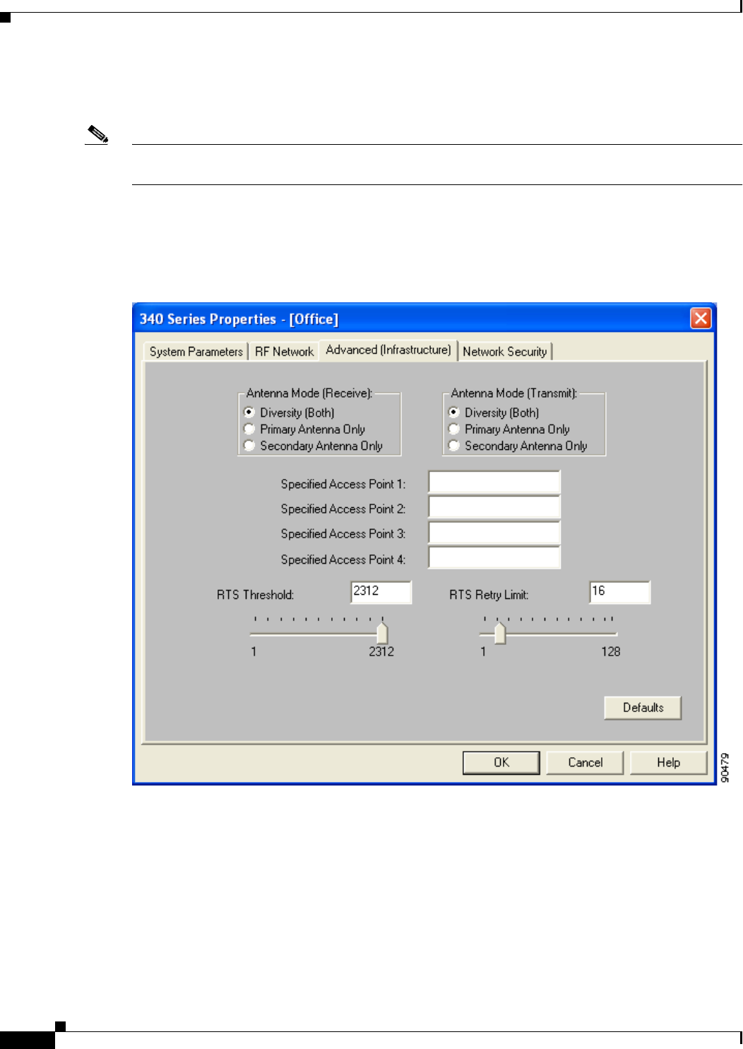
5-14
Cisco Aironet Wireless LAN Client Adapters Installation and Configuration Guide for Windows OL-1394-06
Chapter 5 Configuring the Client Adapter
Setting Advanced Infrastructure Parameters
Setting Advanced Infrastructure Parameters
Note You can set advanced infrastructure parameters only if your client adapter has been set to
operate in an infrastructure network. See the Network Type parameter in Table 5-2.
The Advanced (Infrastructure) screen (see Figure 5-3) enables you to set parameters that control how the
client adapter operates within an infrastructure network. To access this screen, select the Advanced
(Infrastructure) tab from the Properties screens.
Figure 5-3 Advanced (Infrastructure) Screen

5-15
Cisco Aironet Wireless LAN Client Adapters Installation and Configuration Guide for Windows
OL-1394-06
Chapter 5 Configuring the Client Adapter Setting Advanced Infrastructure Parameters
Table 5-4 lists and describes the client adapter’s advanced infrastructure parameters. Follow the
instructions in the table to change any parameters.
Table 5-4 Advanced (Infrastructure) Parameters
Parameter Description
Antenna Mode (Receive) Specifies the antenna that your client adapter uses to receive data.
•PC card—The PC card’s integrated, permanently attached
antenna operates best when used in diversity mode. Diversity
mode allows the card to use the better signal from its two antenna
ports.
Options: Diversity (Both), Primary Antenna Only, Secondary
Antenna Only
Default: Diversity (Both)
•LM card—The LM card is shipped without an antenna; however,
an antenna can be connected through the card’s external
connector. If a snap-on antenna is used, diversity mode is
recommended. Otherwise, select the mode that corresponds to the
antenna port to which the antenna is connected.
Options: Diversity (Both), Primary Antenna Only, Secondary
Antenna Only
Default: Diversity (Both)
•PCI card—The PCI card must use the Primary Antenna Only
option.
Default: Primary Antenna Only
•Mini PCI card—The mini PCI card, which can be used with one
or two antennas, operates best in diversity mode. Diversity mode
allows the card to use the better signal from its two antenna
connectors.
Options: Diversity (Both), Primary Antenna Only, Secondary
Antenna Only
Default: Diversity (Both)
Note This parameter is available only for 2.4-GHz client adapters.
Note The Primary Antenna Only and Secondary Antenna Only
options were formerly named Right Antenna Only and Left
Antenna Only, respectively.
Antenna Mode (Transmit) Specifies the antenna that your client adapter uses to transmit data.
See the Antenna Mode (Receive) parameter above for information on
the options available for your client adapter.
Note This parameter is available only for 2.4-GHz client adapters.

5-16
Cisco Aironet Wireless LAN Client Adapters Installation and Configuration Guide for Windows OL-1394-06
Chapter 5 Configuring the Client Adapter
Setting Advanced Infrastructure Parameters
Go to the next section to set additional parameters or click OK to return to the Profile Manager screen.
On the Profile Manager screen, click OK or Apply to save your changes.
Specified Access Point 1- 4 Specifies the MAC addresses of up to four preferred access points
with which the client adapter can associate. If the specified access
points are not found or the client adapter roams out of range, the
adapter may associate to another access point.
You can enter the MAC addresses of the access points in the edit boxes
or choose not to specify access points by leaving the boxes blank.
Default: Blank fields
Note This parameter should be used only for access points that are
in repeater mode. For normal operation, leave these fields
blank because specifying an access point slows down the
roaming process.
RTS Threshold Specifies the size of the data packet that the low-level RF protocol
issues to a request-to-send (RTS) packet.
Setting this parameter to a small value causes RTS packets to be sent
more often. When this occurs, more of the available bandwidth is
consumed and the throughput of other network packets is reduced, but
the system is able to recover faster from interference or collisions,
which may be caused from a high multipath environment
characterized by obstructions or metallic surfaces.
Range: 0 to 2312
Default: 2312
Note Refer to the IEEE 802.11 Standard for more information on
the RTS/CTS mechanism.
RTS Retry Limit Specifies the number of times the client adapter resends a
request-to-send (RTS) packet if it does not receive a clear-to-send
(CTS) packet from the previously sent RTS packet.
Setting this parameter to a large value decreases the available
bandwidth whenever interference is encountered but makes the system
more immune to interference and collisions, which may be caused
from a high multipath environment characterized by obstructions or
metallic surfaces.
Range: 1 to 128
Default: 16 (2.4-GHz client adapters) or 32 (5-GHz client adapters)
Note Refer to the IEEE 802.11 Standard for more information on
the RTS/CTS mechanism.
Table 5-4 Advanced (Infrastructure) Parameters (continued)
Parameter Description
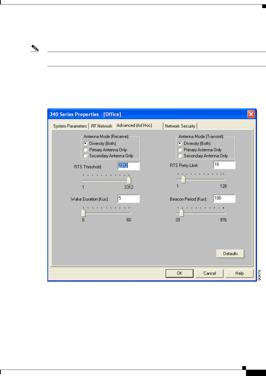
5-17
Cisco Aironet Wireless LAN Client Adapters Installation and Configuration Guide for Windows
OL-1394-06
Chapter 5 Configuring the Client Adapter Setting Advanced Ad Hoc Parameters
Setting Advanced Ad Hoc Parameters
Note You can set advanced ad hoc parameters only if your client adapter has been set to operate in an ad hoc
network. See the Network Type parameter in Table 5-2.
The Advanced (Ad Hoc) screen (see Figure 5-4) enables you to set parameters that control how the client
adapter operates within an ad hoc network. To access this screen, select the Advanced (Ad Hoc) tab
from the Properties screens.
Figure 5-4 Advanced (Ad Hoc) Screen

5-18
Cisco Aironet Wireless LAN Client Adapters Installation and Configuration Guide for Windows OL-1394-06
Chapter 5 Configuring the Client Adapter
Setting Advanced Ad Hoc Parameters
Table 5-5 lists and describes the client adapter’s advanced ad hoc parameters. Follow the instructions in
the table to change any parameters.
Table 5-5 Advanced (Ad Hoc) Parameters
Parameter Description
Antenna Mode (Receive) Specifies the antenna that your client adapter uses to receive data.
•PC card—The PC card’s integrated, permanently attached
antenna operates best when used in diversity mode. Diversity
mode allows the card to use the better signal from its two antenna
ports.
Options: Diversity (Both), Primary Antenna Only, Secondary
Antenna Only
Default: Diversity (Both)
•LM card—The LM card is shipped without an antenna; however,
an antenna can be connected through the card’s external
connector. If a snap-on antenna is used, diversity mode is
recommended. Otherwise, select the mode that corresponds to the
antenna port to which the antenna is connected.
Options: Diversity (Both), Primary Antenna Only, Secondary
Antenna Only
Default: Diversity (Both)
•PCI card—The PCI card must use the Primary Antenna Only
option.
Default: Primary Antenna Only
•Mini PCI card—The mini PCI card, which can be used with one
or two antennas, operates best in diversity mode. Diversity mode
allows the card to use the better signal from its two antenna
connectors.
Options: Diversity (Both), Primary Antenna Only, Secondary
Antenna Only
Default: Diversity (Both)
Note This parameter is available only for 2.4-GHz client adapters.
Note The Primary Antenna Only and Secondary Antenna Only
options were formerly named Right Antenna Only and Left
Antenna Only, respectively.
Antenna Mode (Transmit) Specifies the antenna that your client adapter uses to transmit data.
See the Antenna Mode (Receive) parameter above for information on
the options available for your client adapter.
Note This parameter is available only for 2.4-GHz client adapters.

5-19
Cisco Aironet Wireless LAN Client Adapters Installation and Configuration Guide for Windows
OL-1394-06
Chapter 5 Configuring the Client Adapter Setting Advanced Ad Hoc Parameters
RTS Threshold Specifies the size of the data packet that the low-level RF protocol
issues to a request-to-send (RTS) packet.
Setting this parameter to a small value causes RTS packets to be sent
more often. When this occurs, more of the available bandwidth is
consumed and the throughput of other network packets is reduced, but
the system is able to recover faster from interference or collisions,
which may be caused from a high multipath environment
characterized by obstructions or metallic surfaces.
Range: 0 to 2312
Default: 2312
Note Refer to the IEEE 802.11 Standard for more information on
the RTS/CTS mechanism.
RTS Retry Limit Specifies the number of times the client adapter resends a
request-to-send (RTS) packet if it does not receive a clear-to-send
(CTS) packet from the previously sent RTS packet.
Setting this parameter to a large value decreases the available
bandwidth whenever interference is encountered but makes the system
more immune to interference and collisions, which may be caused
from a high multipath environment characterized by obstructions or
metallic surfaces.
Range: 1 to 128
Default: 16 (2.4-GHz client adapters) or 32 (5-GHz client adapters)
Note Refer to the IEEE 802.11 Standard for more information on
the RTS/CTS mechanism.
Wake Duration (Kµs) Specifies the amount of time following a beacon that the client adapter
stays awake to receive announcement traffic indication message
(ATIM) packets, which are sent to the adapter to keep it awake until
the next beacon.
Refer to the Power Save Mode parameter in Table 5-2.
Range: 0 Kµs (in CAM mode); 5 to 60 Kµs (in Max PSP or Fast PSP
mode)
Default: 5 Kµs
Note If your client adapter is set to CAM mode, you must set the
wake duration to 0 Kµs. If your client adapter is set to Max PSP
or Fast PSP mode, you must set the wake duration to a minimum
of 5 Kµs.
Note Kµs is a unit of measurement in software terms. K = 1024,
µ = 10-6, and s = seconds, so Kµs = .001024 seconds, 1.024
milliseconds, or 1024 microseconds.
Table 5-5 Advanced (Ad Hoc) Parameters (continued)
Parameter Description
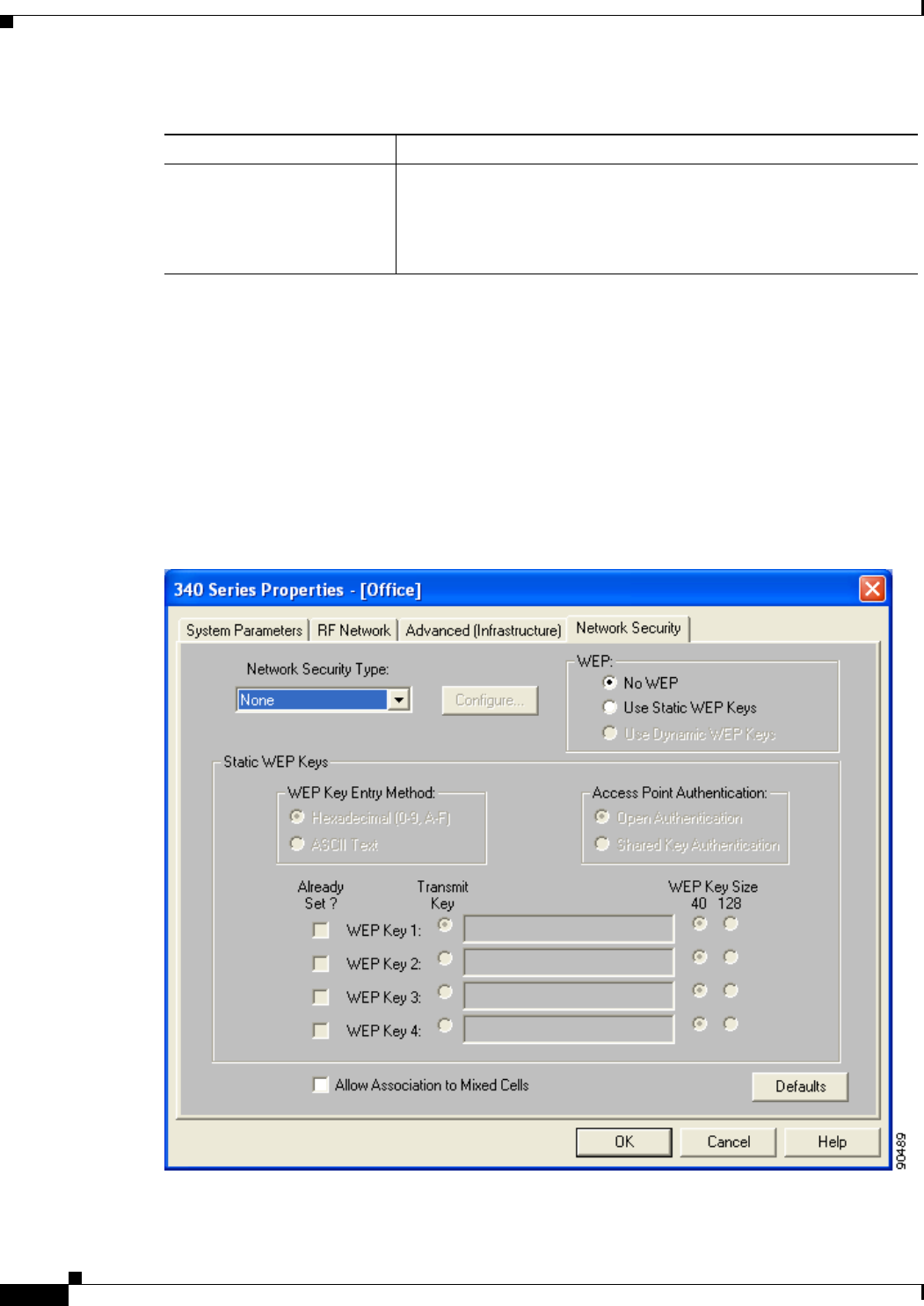
5-20
Cisco Aironet Wireless LAN Client Adapters Installation and Configuration Guide for Windows OL-1394-06
Chapter 5 Configuring the Client Adapter
Setting Network Security Parameters
Go to the next section to set additional parameters or click OK to return to the Profile Manager screen.
On the Profile Manager screen, click OK or Apply to save your changes.
Setting Network Security Parameters
The Network Security screen (see Figure 5-5) enables you to set parameters that control how the client
adapter associates to an access point, authenticates to the wireless network, and encrypts and decrypts
data. To access this screen, select the Network Security tab from the Properties screens.
Figure 5-5 Network Security Screen
Beacon Period (Kµs) Specifies the duration between beacon packets, which are used to help
clients find each other in ad hoc mode.
Range: 20 to 976 Kµs
Default: 100 Kµs
Table 5-5 Advanced (Ad Hoc) Parameters (continued)
Parameter Description

5-21
Cisco Aironet Wireless LAN Client Adapters Installation and Configuration Guide for Windows
OL-1394-06
Chapter 5 Configuring the Client Adapter Setting Network Security Parameters
This screen is different from the other Properties screens in that it presents several security features, each
of which involves a number of steps. In addition, the security features themselves are complex and need
to be understood before they are implemented. Therefore, this section provides an overview of the
security features as well as procedures for using them.
However, before you determine the appropriate security settings for your client adapter, you must decide
how to set the Allow Association to Mixed Cells parameter, which appears at the bottom of the Network
Security screen and is not associated to any of the security features. See the “Setting the Allow
Association to Mixed Cells Parameter” section below.
Setting the Allow Association to Mixed Cells Parameter
The Allow Association to Mixed Cells parameter indicates whether the client adapter can associate to
an access point that allows both WEP and non-WEP associations. Follow the steps below to set this
parameter.
Step 1 Perform one of the following:
•Check the Allow Association to Mixed Cells check box if the access point with which the client
adapter is to associate has WEP set to Optional and WEP is enabled on the client adapter. Otherwise,
the client is unable to establish a connection with the access point.
•Uncheck the Allow Association to Mixed Cells check box if the access point with which the client
adapter is to associate does not have WEP set to Optional. This is the default setting.
Note For security reasons, Cisco recommends that WEP-enabled and WEP-disabled clients not be
allowed in the same cell because broadcast packets are sent unencrypted, even to clients running
WEP.
Step 2 Perform one of the following:
•If you do not want to change any other parameters on the Network Security screen, click OK to
return to the Profile Manager screen; then click OK or Apply to save your changes
•If you want to change some of the other parameters on the Network Security screen, go to the next
section.
Overview of Security Features
You can protect your data as it is transmitted through your wireless network by encrypting it through the
use of wired equivalent privacy (WEP) encryption keys. With WEP encryption, the transmitting device
encrypts each packet with a WEP key, and the receiving device uses that same key to decrypt each
packet.
The WEP keys used to encrypt and decrypt transmitted data can be statically associated with your
adapter or dynamically created as part of the EAP authentication process. The information in the “Static
WEP Keys” and “EAP (with Dynamic WEP Keys)” sections below can help you to decide which type
of WEP keys you want to use. Dynamic WEP keys with EAP offer a higher degree of security than static
WEP keys.

5-22
Cisco Aironet Wireless LAN Client Adapters Installation and Configuration Guide for Windows OL-1394-06
Chapter 5 Configuring the Client Adapter
Setting Network Security Parameters
WEP keys, whether static or dynamic, are either 40 or 128 bits in length. 128-bit WEP keys offer a
greater level of security than 40-bit WEP keys.
Note Refer to the “Additional WEP Key Security Features” section on page 5-25 for information on three
security features that can make your WEP keys even more secure.
Static WEP Keys
Each device (or profile) within your wireless network can be assigned up to four static WEP keys. If a
device receives a packet that is not encrypted with the appropriate key (as the WEP keys of all devices
that are to communicate with each other must match), the device discards the packet and never delivers
it to the intended receiver.
Static WEP keys are write-only and temporary; therefore, they cannot be read back from the client
adapter, and they are lost when power to the adapter is removed or the Windows device is rebooted.
Although the keys are temporary, you do not need to re-enter them each time the client adapter is inserted
or the Windows device is rebooted. This is because the keys are stored (in an encrypted format for
security reasons) in the registry of the Windows device. When the driver loads and reads the client
adapter’s registry parameters, it also finds the static WEP keys, unencrypts them, and stores them in
volatile memory on the adapter.
The Network Security screen enables you to view the current WEP key settings for the client adapter and
then to assign new WEP keys or overwrite existing WEP keys as well as to enable or disable static WEP.
Refer to the “Using Static WEP” section on page 5-29 for instructions.
EAP (with Dynamic WEP Keys)
The new standard for wireless LAN security, as defined by the Institute of Electrical and Electronics
Engineers (IEEE), is called 802.1X for 802.11, or simply 802.1X. An access point that supports 802.1X
and its protocol, Extensible Authentication Protocol (EAP), acts as the interface between a wireless
client and an authentication server, such as a Remote Authentication Dial-In User Service (RADIUS)
server, to which the access point communicates over the wired network.
Two 802.1X authentication types can be selected in ACU for use with Windows operating systems:
•EAP-Cisco Wireless (or LEAP)—This authentication type is available for Windows 98, 98 SE, NT,
2000, Me, and XP, as well as non-Windows systems. Support for LEAP is provided not in the
Windows operating system but in your client adapter’s firmware and the Cisco software that
supports it. RADIUS servers that support LEAP include Cisco Secure ACS version 2.6 and greater,
Cisco Access Registrar version 1.7 and greater, and Funk Software’s Steel-Belted RADIUS version
3.0 and greater.
LEAP is enabled or disabled for a specific profile through ACU, provided the LEAP security module
was selected during installation. After LEAP is enabled, a variety of configuration options are
available, including how and when a username and password are entered to begin the authentication
process.
The username and password are used by the client adapter to perform mutual authentication with the
RADIUS server through the access point. The username and password are stored in the client adapter’s
volatile memory; therefore, they are temporary and need to be re-entered whenever power is removed
from the adapter, typically due to the client adapter being ejected or the system powering down.

5-23
Cisco Aironet Wireless LAN Client Adapters Installation and Configuration Guide for Windows
OL-1394-06
Chapter 5 Configuring the Client Adapter Setting Network Security Parameters
Note If the LEAP security module was not selected during installation, the LEAP option is
unavailable in ACU. If you want to be able to enable and disable LEAP, you must run the
installation program again and select LEAP.
•Host Based EAP—Selecting this option enables you to use any 802.1X authentication type for
which your operating system has support. For example, if your operating system uses the Microsoft
802.1X supplicant, it provides native support for EAP-TLS authentication and general support for
PEAP and EAP-SIM authentication.
Note To use EAP-TLS, PEAP, or EAP-SIM authentication, you must install the Microsoft 802.1X
supplicant, ACU, and the PEAP or EAP-SIM security module; configure your client adapter
using ACU; enable the authentication type in Windows; and enable Network-EAP on the
access point.
–
EAP-TLS—EAP-TLS is enabled or disabled through the operating system and uses a dynamic
session-based WEP key, which is derived from the client adapter and RADIUS server, to encrypt
data. Once enabled, a few configuration parameters must be set within the operating system.
RADIUS servers that support EAP-TLS include Cisco Secure ACS version 3.0 or greater and
Cisco Access Registrar version 1.8 or greater.
Note EAP-TLS requires the use of a certificate. Refer to Microsoft’s documentation for
information on downloading and installing the certificate.
–
Protected EAP (or PEAP)—PEAP authentication is designed to support One-Time Password
(OTP), Windows NT or 2000 domain, and LDAP user databases over a wireless LAN. It is based
on EAP-TLS authentication but uses a password or PIN instead of a client certificate for
authentication. PEAP is enabled or disabled through the operating system and uses a dynamic
session-based WEP key, which is derived from the client adapter and RADIUS server, to encrypt
data. If your network uses an OTP user database, PEAP requires you to enter either a hardware
token password or a software token PIN to start the EAP authentication process and gain access
to the network. If your network uses a Windows NT or 2000 domain user database or an LDAP
user database (such as NDS), PEAP requires you to enter your username, password, and domain
name in order to start the authentication process.
RADIUS servers that support PEAP authentication include Cisco Secure ACS version 3.1 or
greater.
Note Service Pack 1 for Windows XP and the Microsoft 802.1X supplicant for Windows 2000
include Microsoft’s PEAP supplicant, which supports a Windows username and
password only and does not interoperate with Cisco’s PEAP supplicant. To use Cisco’s
PEAP supplicant, install the Install Wizard file after Service Pack 1 for Windows XP or
the Microsoft 802.1X supplicant for Windows 2000. Otherwise, Cisco’s PEAP
supplicant is overwritten by Microsoft’s PEAP supplicant.

5-24
Cisco Aironet Wireless LAN Client Adapters Installation and Configuration Guide for Windows OL-1394-06
Chapter 5 Configuring the Client Adapter
Setting Network Security Parameters
–
EAP-SIM—EAP-SIM authentication is designed for use in public wireless LANs and requires
clients equipped with PCSC-compliant smartcard readers. The EAP-SIM supplicant included in
the Install Wizard file supports only Gemplus SIM+ cards; however, an updated supplicant is
available that supports standard GSM-SIM cards as well as more recent versions of the
EAP-SIM protocol. The new supplicant is available for download from the ftpeng FTP server
at the following URL:
ftp://ftpeng.cisco.com/ftp/pwlan/eapsim/CiscoEapSim.dll
Please note that the above requirements are necessary but not sufficient to successfully perform
EAP-SIM authentication. Typically, you are also required to enter into a service contract with
a WLAN service provider, who must support EAP-SIM authentication in its network. Also,
while your PCSC smartcard reader may be able to read standard GSM-SIM cards or chips,
EAP-SIM authentication usually requires your GSM cell phone account to be provisioned for
WLAN service by your service provider.
EAP-SIM is enabled or disabled through the operating system and uses a dynamic session-based
WEP key, which is derived from the client adapter and RADIUS server, to encrypt data.
EAP-SIM requires you to enter a user verification code, or PIN, for communication with the
SIM card. You can choose to have the PIN stored in your computer or to be prompted to enter
it after a reboot or prior to every authentication attempt.
RADIUS servers that support EAP-SIM include Cisco Access Registrar version 3.0 or greater.
Note Because EAP-TLS, PEAP, and EAP-SIM authentication are enabled in the operating system
and not in ACU, you cannot switch between these authentication types simply by switching
profiles in ACU. You can create a profile in ACU that uses host-based EAP, but you must
enable the specific authentication type in Windows (provided Windows uses the Microsoft
802.1X supplicant). In addition, Windows can be set for only one authentication type at a
time; therefore, if you have more than one profile in ACU that uses host-based EAP and you
want to use another authentication type, you must change authentication types in Windows
after switching profiles in ACU.
When you enable Network-EAP or Require EAP on your access point and configure your client adapter
for LEAP, EAP-TLS, PEAP, or EAP-SIM, authentication to the network occurs in the following
sequence:
1. The client associates to an access point and begins the authentication process.
Note The client does not gain full access to the network until authentication between the client
and the RADIUS server is successful.
2. Communicating through the access point, the client and RADIUS server complete the authentication
process, with the password (LEAP and PEAP), certificate (EAP-TLS), or internal key stored on the
SIM card and in the service provider’s Authentication Center (EAP-SIM) being the shared secret for
authentication. The password or internal key is never transmitted during the process.
3. If authentication is successful, the client and RADIUS server derive a dynamic, session-based WEP
key that is unique to the client.
4. The RADIUS server transmits the key to the access point using a secure channel on the wired LAN.
5. For the length of a session, or time period, the access point and the client use this key to encrypt or
decrypt all unicast packets (and broadcast packets if the access point is set up to do so) that travel
between them.

5-25
Cisco Aironet Wireless LAN Client Adapters Installation and Configuration Guide for Windows
OL-1394-06
Chapter 5 Configuring the Client Adapter Setting Network Security Parameters
Refer to the “Enabling LEAP” section on page 5-31 for instructions on enabling LEAP or to the
“Enabling Host-Based EAP” section on page 5-34 for instructions on enabling EAP-TLS, PEAP, or
EAP-SIM.
Note Refer to the IEEE 802.11 Standard for more information on 802.1X authentication and to the following
URL for additional information on RADIUS servers:
http://www.cisco.com/univercd/cc/td/doc/product/software/ios120/12cgcr/secur_c/scprt2/scrad.htm
Additional WEP Key Security Features
The three security features discussed in this section (MIC, TKIP, and broadcast key rotation) are
designed to prevent sophisticated attacks on your wireless network’s WEP keys. These features do not
need to be enabled on the client adapter; they are supported automatically in the firmware and driver
versions included in the Install Wizard file. However, they must be enabled on the access point.
Note Access point firmware version 11.10T or greater is required to enable these security features. Refer to
the documentation for your access point for instructions on enabling these security features.
Message Integrity Check (MIC)
MIC prevents bit-flip attacks on encrypted packets. During a bit-flip attack, an intruder intercepts an
encrypted message, alters it slightly, and retransmits it, and the receiver accepts the retransmitted
message as legitimate. The MIC adds a few bytes to each packet to make the packets tamper-proof.
The Status screen indicates if MIC is being used, and the Statistics screen provides MIC statistics.
Note If you enable MIC on the access point, your client adapter’s driver must support these features;
otherwise, the client cannot associate.
Temporal Key Integrity Protocol (TKIP)
This feature, also referred to as WEP key hashing, defends against an attack on WEP in which the
intruder uses the initialization vector (IV) in encrypted packets to calculate the WEP key. TKIP removes
the predictability that an intruder relies on to determine the WEP key by exploiting IVs. It protects both
unicast and broadcast WEP keys.
Note If you enable TKIP on the access point, your client adapter’s firmware must support these features;
otherwise, the client cannot associate.
Broadcast Key Rotation
EAP authentication provides dynamic unicast WEP keys for client devices but uses static broadcast, or
multicast, keys. When you enable broadcast WEP key rotation, the access point provides a dynamic
broadcast WEP key and changes it at the interval you select. When you enable this feature, only wireless
client devices using LEAP, EAP-TLS, PEAP, or EAP-SIM authentication can associate to the access
point. Client devices using static WEP (with open or shared key authentication) cannot associate.

5-26
Cisco Aironet Wireless LAN Client Adapters Installation and Configuration Guide for Windows OL-1394-06
Chapter 5 Configuring the Client Adapter
Setting Network Security Parameters
Reporting Access Points that Fail LEAP Authentication
Client adapter firmware version 5.02.20 or greater and the following access point firmware versions
support a new feature that is designed to detect access points that fail LEAP authentication:
•12.00T or greater (340, 350, and 1200 series access points)
•12.2(4)JA or greater (1100 series access points)
An access point running one of these firmware versions records a message in the system log when a
client running firmware version 5.02.20 or greater discovers and reports another access point in the
wireless network that has failed LEAP authentication.
The process takes place as follows:
1. A client with a LEAP profile attempts to associate to access point A.
2. Access point A does not handle LEAP authentication successfully, perhaps because the access point
does not understand LEAP or cannot communicate to a trusted LEAP authentication server.
3. The client records the MAC address for access point A and the reason why the association failed.
4. The client associates successfully to access point B.
5. The client sends the MAC address of access point A and the reason code for the failure to access
point B.
6. Access point B logs the failure in the system log.
Note This feature does not need to be enabled on the client adapter or access point; it is supported
automatically in the firmware of both devices. However, both the client and access point must use
these firmware versions or greater.
Fast Secure Roaming
Some applications that run on a client device may require fast roaming between access points. Voice
applications, for example, require seamless roaming to prevent delays and gaps in conversation. Support
for fast secure roaming is now available for LEAP-enabled clients in client adapter firmware version
5.20.17.
During normal operation, LEAP-enabled clients mutually authenticate with a new access point by
performing a complete LEAP authentication, including communication with the main RADIUS server.
However, when you configure your wireless LAN for fast secure roaming, LEAP-enabled clients
securely roam from one access point to another without the need to reauthenticate with the RADIUS
server. Using Cisco Centralized Key Management (CCKM), an access point that is configured for
wireless domain services (WDS) uses a fast rekeying technique that enables client devices to roam from
one access point to another in under 150 milliseconds (ms). Fast secure roaming ensures that there is no
perceptible delay in time-sensitive applications such as wireless Voice over IP (VoIP), enterprise
resource planning (ERP), or Citrix-based solutions.
This feature does not need to be enabled on the client adapter; it is supported automatically in client
adapter firmware version 5.20.17 or greater (which is included in Install Wizard version 1.1 or greater).
However, it must be enabled on the access point.
Note Access point firmware version 12.2(11)JA or greater is required to enable fast roaming. Refer to the
documentation for your access point for instructions on enabling this feature.

5-27
Cisco Aironet Wireless LAN Client Adapters Installation and Configuration Guide for Windows
OL-1394-06
Chapter 5 Configuring the Client Adapter Setting Network Security Parameters
Note If the Microsoft 802.1X supplicant is installed on your computer, you must disable one or two Windows
parameters in order for this feature to operate correctly. Refer to Step 10 in the “Enabling LEAP” section
for details.
Synchronizing Security Features
In order to use any of the security features discussed in this section, both your client adapter and the
access point to which it will associate must be set appropriately. Table 5-6 indicates the client and access
point settings required for each security feature. This chapter provides specific instructions for enabling
the security features on your client adapter. Refer to the documentation for your access point for
instructions on enabling any of these features on the access point.
Table 5-6 Client and Access Point Security Settings
Security Feature Client Setting Access Point Setting
Static WEP with open
authentication Create a WEP key and enable Use
Static WEP Keys and Open
Authentication
Set up and enable WEP and enable
Open Authentication
Static WEP with shared key
authentication Create a WEP key and enable Use
Static WEP Keys and Shared Key
Authentication
Set up and enable WEP and enable
Shared Key Authentication
LEAP authentication Enable LEAP Set up and enable WEP and enable
Network-EAP
EAP-TLS authentication
If using ACU to
configure card Enable Host Based EAP and Use
Dynamic WEP Keys in ACU and
select Enable network access
control using IEEE 802.1X and
Certificates (or Smart Card or
Other Certificate) as the EAP Type
in Windows
Set up and enable WEP and enable
Network-EAP
If using Windows XP
to configure card Select Enable network access
control using IEEE 802.1X and
Smart Card or other Certificate as
the EAP Type
Set up and enable WEP and enable
Require EAP and Open
Authentication
PEAP authentication
If using ACU to
configure card Enable Host Based EAP and Use
Dynamic WEP Keys in ACU and
select Enable network access
control using IEEE 802.1X and
PEAP as the EAP Type in Windows
Set up and enable WEP and enable
Network-EAP
If using Windows XP
to configure card Select Enable network access
control using IEEE 802.1X and
PEAP as the EAP Type
Set up and enable WEP and enable
Require EAP and Open
Authentication

5-28
Cisco Aironet Wireless LAN Client Adapters Installation and Configuration Guide for Windows OL-1394-06
Chapter 5 Configuring the Client Adapter
Setting Network Security Parameters
EAP-SIM authentication
If using ACU to
configure card Enable Host Based EAP and Use
Dynamic WEP Keys in ACU and
select Enable network access
control using IEEE 802.1X and
SIM Authentication as the EAP
Type in Windows
Set up and enable WEP with full
encryption and enable
Network-EAP
If using Windows XP
to configure card Select Enable network access
control using IEEE 802.1X and
SIM Authentication as the EAP
Type
Set up and enable WEP with full
encryption and enable Require
EAP and Open Authentication
MIC No settings required; automatically
enabled by the driver included in
the Install Wizard file
Set up and enable WEP with full
encryption, set MIC to MMH, and
set Use Aironet Extensions to Yes
TKIP No settings required; automatically
enabled by the firmware included
in the Install Wizard file
Set up and enable WEP, set TKIP to
Cisco, and set Use Aironet
Extensions to Yes
Broadcast key rotation Enable LEAP, EAP-TLS, PEAP, or
EAP-SIM and use the firmware
included in the Install Wizard file
Set up and enable WEP and set
Broadcast WEP Key Rotation
Interval to any value other than
zero (0)
Reporting access points
that fail LEAP
authentication
No settings required; automatically
enabled in firmware version
5.02.20 or greater
No settings required; automatically
enabled in the following firmware
versions: 12.00T or greater (340,
350, and 1200 series access points)
or 12.2(4)JA or greater (1100 series
access points)
Fast secure roaming Enable LEAP and use firmware
version 5.20.17 or greater Use firmware version 12.2(11)JA
or greater, select a cipher suite, and
enable open authentication with
EAP and CCKM
Note To allow both 802.1X
clients and non-802.1X
clients to use the SSID,
enable optional CCKM.
Table 5-6 Client and Access Point Security Settings (continued)
Security Feature Client Setting Access Point Setting

5-29
Cisco Aironet Wireless LAN Client Adapters Installation and Configuration Guide for Windows
OL-1394-06
Chapter 5 Configuring the Client Adapter Setting Network Security Parameters
Using Static WEP
This section provides instructions for entering new static WEP keys or overwriting existing static WEP
keys.
Entering a New Static WEP Key
Follow the steps below to enter a new static WEP key for this profile.
Step 1 Select None from the Network Security Type drop-down box on the Network Security screen.
Step 2 Select Use Static WEP Keys under WEP.
Step 3 Select one of the following WEP key entry methods:
•Hexadecimal (0-9, A-F)—Specifies that the WEP key will be entered in hexadecimal characters,
which include 0-9, A-F, and a-f.
•ASCII Text—Specifies that the WEP key will be entered in ASCII text, which includes alpha
characters, numbers, and punctuation marks.
Note ASCII text WEP keys are not supported on the Cisco Aironet 1200 Series Access Points, so
you must select the Hexadecimal (0-9, A-F) option if you are planning to use your client
adapter with these access points.
Step 4 Select one of the following access point authentication options, which defines how your client adapter
will attempt to authenticate to an access point:
•Open Authentication—Enables your client adapter, regardless of its WEP settings, to authenticate
and attempt to communicate with an access point. Open Authentication is the default setting.
•Shared Key Authentication—Enables your client adapter to communicate only with access points
that have the same WEP key. This option is available only if Use Static WEP Keys is selected.
In shared key authentication, the access point sends a known unencrypted “challenge packet” to the
client adapter, which encrypts the packet and sends it back to the access point. The access point
attempts to decrypt the encrypted packet and sends an authentication response packet indicating the
success or failure of the decryption back to the client adapter. If the packet is successfully
encrypted/decrypted, the user is considered to be authenticated.
Note Cisco recommends that shared key authentication not be used because it presents a security
risk.
Step 5 For the static WEP key that you are entering (1, 2, 3, or 4), select a WEP key size of 40 or 128 on the
right side of the screen. 128-bit client adapters can use 40- or 128-bit keys, but 40-bit adapters can use
only 40-bit keys. If 128 bit is not supported by the client adapter, this option is unavailable.

5-30
Cisco Aironet Wireless LAN Client Adapters Installation and Configuration Guide for Windows OL-1394-06
Chapter 5 Configuring the Client Adapter
Setting Network Security Parameters
Step 6 Obtain the static WEP key from your system administrator and enter it in the blank field for the key you
are creating. Follow the guidelines below to enter a new static WEP key:
•WEP keys must contain the following number of characters:
–
10 hexadecimal characters or 5 ASCII text characters for 40-bit keys
Example: 5A5A313859 (hexadecimal) or ZZ18Y (ASCII)
–
26 hexadecimal characters or 13 ASCII text characters for 128-bit keys
Example: 5A583135333554595549333534 (hexadecimal) or ZX1535TYUI354 (ASCII)
Note You must enter hexadecimal characters for 5-GHz client adapters if these adapters will be
used with Cisco Aironet 1200 Series Access Points.
•Your client adapter’s WEP key must match the WEP key used by the access point (in infrastructure
mode) or clients (in ad hoc mode) with which you are planning to communicate.
•When setting more than one WEP key, the keys must be assigned to the same WEP key numbers for
all devices. For example, WEP key 2 must be WEP key number 2 on all devices. When multiple
WEP keys are set, they must be in the same order on all devices.
Note After you enter a WEP key, you can write over it, but you cannot edit or delete it.
Step 7 Click the Transmit Key button to the left of the key you want to use to transmit packets. Only one WEP
key can be selected as the transmit key.
Step 8 Click OK to return to the Profile Manager screen; then click OK or Apply to save your changes.
Overwriting an Existing Static WEP Key
Follow the steps below to overwrite an existing static WEP key.
Note You can overwrite existing WEP keys, but you cannot edit or delete them.
Step 1 Look at the current WEP key settings in the middle of the Network Security screen. A checkmark
appears in the Already Set? box for all existing static WEP keys.
Note For security reasons, the codes for existing static WEP keys do not appear on the screen.
Step 2 Decide which existing static WEP key you want to overwrite.
Step 3 Click within the blank field of that key.
Step 4 Enter a new key, following the guidelines outlined in Step 6 of the “Entering a New Static WEP Key”
section on page 5-29.

5-31
Cisco Aironet Wireless LAN Client Adapters Installation and Configuration Guide for Windows
OL-1394-06
Chapter 5 Configuring the Client Adapter Setting Network Security Parameters
Step 5 Make sure the Transmit Key button to the left of your key is selected, if you want this key to be used to
transmit packets.
Step 6 Click OK to return to the Profile Manager screen; then click OK or Apply to save your changes
Disabling Static WEP
If you ever need to disable static WEP for a particular profile, select No WEP under WEP on the
Network Security screen, click OK, and click OK or Apply on the Profile Manager screen.
Note Selecting LEAP from the Network Security Type drop-down box on the Network Security screen
disables static WEP automatically.
Enabling LEAP
Before you can enable LEAP authentication, your network devices must meet the following
requirements:
•Client adapters must support WEP and use the firmware, drivers, utilities, and security modules
included in the Install Wizard file.
Note To use the reporting access points that fail LEAP authentication and fast secure roaming
features, client adapters must use the software included in Install Wizard version 1.1 or
greater.
•Access points to which your client adapter may attempt to authenticate must use the following
software versions or greater: firmware version 12.00T (340, 350, and 1200 series access points) or
IOS release 12.2(4)JA (1100 series access points).
Note To use the reporting access points that fail LEAP authentication and fast secure roaming
features, access points must use the firmware versions listed on page 5-26.
•All necessary infrastructure devices (for example, access points, servers, etc.) must be properly
configured for LEAP authentication.
Follow the steps below to enable LEAP authentication for this profile.
Step 1 Select LEAP from the Network Security Type drop-down box on the bottom of the Network Security
screen.
Note The LEAP option is available only if you selected the LEAP security module during installation.
Note When you select this option, dynamic WEP is set automatically.
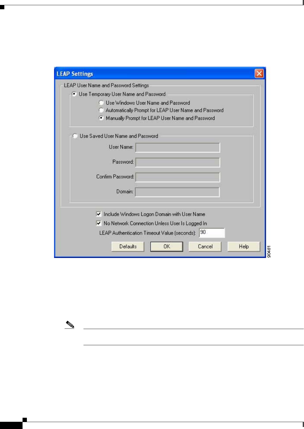
5-32
Cisco Aironet Wireless LAN Client Adapters Installation and Configuration Guide for Windows OL-1394-06
Chapter 5 Configuring the Client Adapter
Setting Network Security Parameters
Step 2 Click Configure to the right of the Network Security Type drop-down box. The LEAP Settings screen
appears (see Figure 5-6).
Figure 5-6 LEAP Settings Screen
Step 3 Select one of the following LEAP username and password setting options:
•Use Temporary User Name and Password—Requires you to enter the LEAP username and
password each time the computer reboots in order to authenticate and gain access to the network.
•Use Saved User Name and Password—Does not require you to enter a LEAP username and
password each time the computer reboots. Authentication occurs automatically as needed using a
saved username and password (which are registered with the RADIUS server).
Note The Use Saved User Name and Password option is available only if the Allow Saved LEAP
User Name and Password option was enabled (set to Yes) during installation.

5-33
Cisco Aironet Wireless LAN Client Adapters Installation and Configuration Guide for Windows
OL-1394-06
Chapter 5 Configuring the Client Adapter Setting Network Security Parameters
Step 4 Perform one of the following:
•If you selected Use Temporary User Name and Password in Step 3, select one of the following
options:
–
Use Windows User Name and Password—Causes your Windows username and password to
also serve as your LEAP username and password, giving you only one set of credentials to
remember. After you log in, the LEAP authentication process begins automatically. This option
is the default setting.
–
Automatically Prompt for LEAP User Name and Password—Requires you to enter a
separate LEAP username and password (which are registered with the RADIUS server) in
addition to your regular Windows login in order to start the LEAP authentication process.
–
Manually Prompt for LEAP User Name and Password—Requires you to manually invoke
the LEAP authentication process as needed using the Manual LEAP Login option from the
Commands drop-down menu. You are not prompted to enter a LEAP username and password
during the Windows login. This option might be used to support a software token one-time
password system or other systems that require additional software that is not available at login.
•If you selected Use Saved User Name and Password in Step 3, follow the steps below:
a. Enter a username and password in the appropriate fields.
Note Usernames and passwords are limited to 32 ASCII characters each. However, if a
domain name is entered in the Domain field, the sum of the username and domain name
is limited to 31 ASCII characters.
b. Re-enter the password in the Confirm Password field.
c. If you wish to specify a domain name that will be passed to the RADIUS server along with your
username, enter it in the Domain field.
Step 5 If you work in an environment with multiple domains and, therefore, want your Windows login domain
to be passed to the RADIUS server along with your username, check the Include Windows Logon
Domain with User Name check box. The default setting is checked.
Note If you selected to use a saved username and password but do not check the Include Windows
Logon Domain with User Name check box, the Domain field becomes unavailable, and a
domain name is not passed to the RADIUS server.
Step 6 If you want to force the client adapter to disassociate after you log off so that another user cannot gain
access to the wireless network using your credentials, check the No Network Connection Unless User
Is Logged In check box. The default setting is checked.
Step 7 In the LEAP Authentication Timeout Value field, enter the amount of time (in seconds) before a LEAP
authentication is considered to be failed and an error message appears.
Range: 45 to 300 seconds
Default: 90 seconds
Step 8 Click OK to exit the LEAP Settings screen.
Step 9 Click OK to exit the Network Security screen and return to the Profile Manager screen. On the Profile
Manager screen, click OK or Apply to save your changes.

5-34
Cisco Aironet Wireless LAN Client Adapters Installation and Configuration Guide for Windows OL-1394-06
Chapter 5 Configuring the Client Adapter
Setting Network Security Parameters
Step 10 Follow the steps below if the Microsoft 802.1X supplicant is installed on your computer and you want
to take advantage of the fast secure roaming feature:
a. Perform one of the following steps, depending on your computer’s operating system:
–
If your computer is running Windows 98, 98 SE, NT, or Me, run the Microsoft 802.1X
Authentication Client application. Then go to Step c.
–
If your computer is running Windows 2000, double-click My Computer, Control Panel, and
Network and Dial-up Connections. Right-click Local Area Connection. Click Properties.
The Local Area Connection Properties screen appears.
–
If your computer is running Windows XP, double-click My Computer,Control Panel, and
Network Connections. Right-click Wireless Network Connection. Click Properties. The
Wireless Network Connection Properties screen appears. Uncheck the Use Windows to
configure my wireless network settings check box.
b. Click the Authentication tab.
Note In Service Pack 1 for Windows XP, the Authentication tab has moved from its previous
location. To access it, click the Wireless Networks tab, select the network that you are
configuring in the Preferred network list, and click Properties.
c. Uncheck the Enable network access control using IEEE 802.1X check box.
Step 11 Refer to Chapter 6 for instructions on authenticating using LEAP.
Enabling Host-Based EAP
Before you can enable host-based EAP authentication, your network devices must meet the following
requirements:
•Client adapters must support WEP and use the firmware, drivers, utilities, and security modules
included in the Install Wizard file.
•Access points to which your client adapter may attempt to authenticate must use the following
software versions or greater: firmware version 12.00T (340, 350, and 1200 series access points) or
IOS release 12.2(4)JA (1100 series access points).
•The Microsoft 802.1X supplicant must be installed on your Windows device.
•All necessary infrastructure devices (for example, access points, servers, gateways, user databases,
etc.) must be properly configured for the authentication type you plan to enable on the client.
Follow the steps below to enable host-based EAP authentication (EAP-TLS, PEAP, or EAP-SIM) for this
profile.
Note Because EAP-TLS, PEAP, and EAP-SIM authentication are enabled in the operating system and not in
ACU, you cannot switch between these authentication types simply by switching profiles in ACU. You
can create a profile in ACU that uses host-based EAP, but you must enable the specific authentication
type in Windows (provided Windows uses the Microsoft 802.1X supplicant). In addition, Windows can
be set for only one authentication type at a time; therefore, if you have more than one profile in ACU
that uses host-based EAP and you want to use another authentication type, you must change
authentication types in Windows after switching profiles in ACU.

5-35
Cisco Aironet Wireless LAN Client Adapters Installation and Configuration Guide for Windows
OL-1394-06
Chapter 5 Configuring the Client Adapter Setting Network Security Parameters
Step 1 Select Host Based EAP from the Network Security Type drop-down box on the Network Security
screen.
Step 2 Select Use Dynamic WEP Keys under WEP.
Step 3 Click OK to return to the Profile Manager screen.
Step 4 Click OK or Apply on the Profile Manager screen to save your changes.
Step 5 Perform one of the following, depending on your computer’s operating system:
•If your computer is running Windows 98, 98 SE, NT, or Me, run the Microsoft 802.1X
Authentication Client application. Then go to Step 7.
•If your computer is running Windows 2000, double-click My Computer, Control Panel, and
Network and Dial-up Connections. Right-click Local Area Connection. Click Properties. The
Local Area Connection Properties screen appears.
•If your computer is running Windows XP, double-click My Computer,Control Panel, and
Network Connections. Right-click Wireless Network Connection. Click Properties. The
Wireless Network Connection Properties screen appears.
Note These instructions assume you are using Windows XP’s classic view rather than its category
view.
Step 6 Click the Authentication tab. The following screen appears (see Figure 5-7).
Note In Service Pack 1 for Windows XP, the Authentication tab has moved from its previous location.
To access it, click the Wireless Networks tab, select the network that you are configuring in the
Preferred network list, and click Properties.
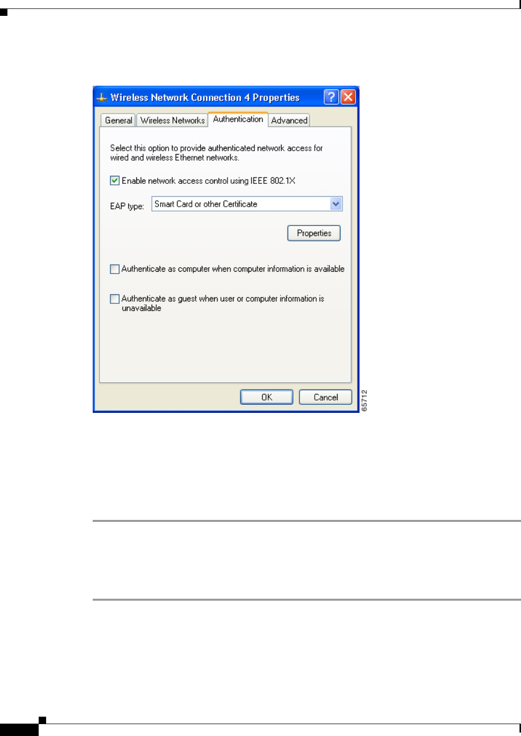
5-36
Cisco Aironet Wireless LAN Client Adapters Installation and Configuration Guide for Windows OL-1394-06
Chapter 5 Configuring the Client Adapter
Setting Network Security Parameters
Figure 5-7 Wireless Network Connection Properties Screen (Authentication Tab) - Windows 2000 and
XP Only
Step 7 Check the Enable network access control using IEEE 802.1X check box.
Step 8 Perform one of the following, depending on the authentication type you want to use:
•If you are planning to use EAP-TLS, go to the “Enabling EAP-TLS” section below.
•If you are planning to use PEAP, go to the “Enabling PEAP” section on page 5-39.
•If you are planning to use EAP-SIM, go to the “Enabling EAP-SIM” section on page 5-41.
Enabling EAP-TLS
Follow the steps below to enable EAP-TLS.
Step 1 For EAP type, select Certificates (on Windows 98, 98 SE, NT, or Me) or Smart Card or other
Certificate (on Windows 2000 or XP).
Step 2 Click Properties. The Certificate Properties screen (see Figure 5-8) or the Smart Card or other
Certificate Properties screen appears (see Figure 5-9).
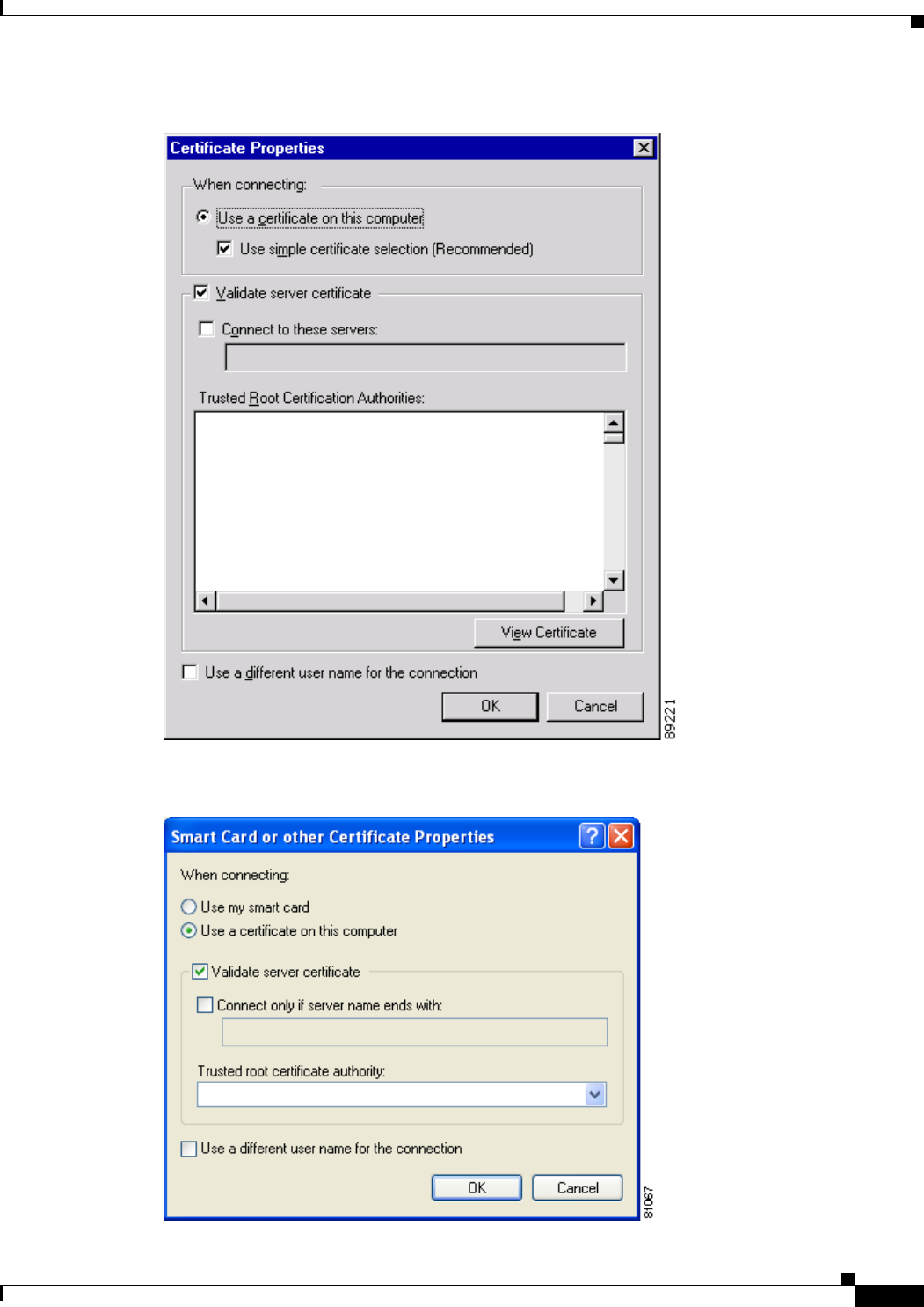
5-37
Cisco Aironet Wireless LAN Client Adapters Installation and Configuration Guide for Windows
OL-1394-06
Chapter 5 Configuring the Client Adapter Setting Network Security Parameters
Figure 5-8 Certificate Properties Screen - Windows 98, 98 SE, NT, and Me Only
Figure 5-9 Smart Card or other Certificate Properties Screen - Windows 2000 and XP Only

5-38
Cisco Aironet Wireless LAN Client Adapters Installation and Configuration Guide for Windows OL-1394-06
Chapter 5 Configuring the Client Adapter
Setting Network Security Parameters
Step 3 Select the Use a certificate on this computer option.
Step 4 If your computer is running Windows 98, 98 SE, NT, or Me, make sure the Use simple certificate
selection (Recommended) check box is selected.
Step 5 Check the Validate server certificate check box if server certificate validation is required.
Step 6 If you want to specify the name of the server to connect to, check the Connect to these servers or
Connect only if server name ends with check box and enter the appropriate server name or server name
suffix in the field below.
Note If you enter a server name and the client adapter connects to a server that does not match the
name you entered, you are prompted to accept or cancel the connection during the authentication
process.
Note If you leave this field blank, the server name is not verified, and a connection is established as
long as the certificate is valid.
Step 7 Perform one of the following:
•If your computer is running Windows 98, 98 SE, NT, or Me, select the certificate authority from
which the server certificate was downloaded in the Trusted Root Certification Authorities field.
•If your computer is running Windows 2000 or XP, make sure that the name of the certificate
authority from which the server certificate was downloaded appears in the Trusted root certificate
authority field.
Note If you leave this field blank, you are prompted to accept a connection to the root certification
authority during the authentication process.
Step 8 Click OK twice to save your settings. The configuration is complete.
Step 9 Refer to Chapter 6 for instructions on authenticating using EAP-TLS.
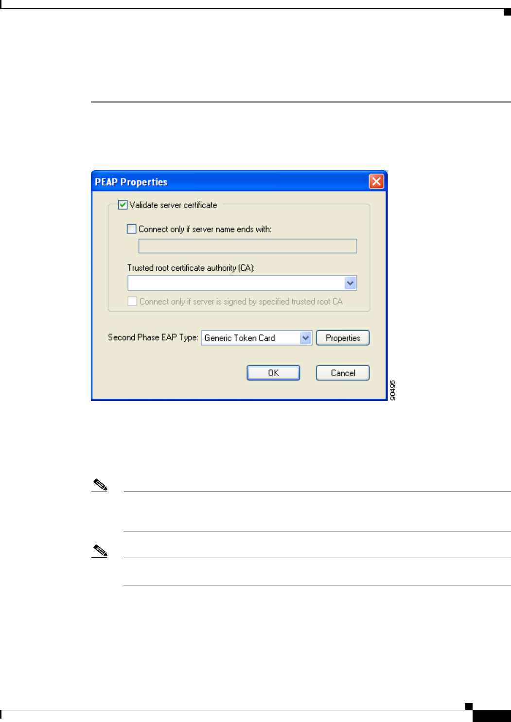
5-39
Cisco Aironet Wireless LAN Client Adapters Installation and Configuration Guide for Windows
OL-1394-06
Chapter 5 Configuring the Client Adapter Setting Network Security Parameters
Enabling PEAP
Follow the steps below to enable PEAP.
Step 1 For EAP type, select PEAP.
Step 2 Click Properties. The PEAP Properties screen appears (see Figure 5-10).
Figure 5-10 PEAP Properties Screen
Step 3 Check the Validate server certificate check box if server certificate validation is required
(recommended).
Step 4 If you want to specify the name of the server to connect to, check the Connect only if server name ends
with check box and enter the appropriate server name suffix in the field below.
Note If you enter a server name and the client adapter connects to a server that does not match the
name you entered, you are prompted to accept or cancel the connection during the authentication
process.
Note If you leave this field blank, the server name is not verified, and a connection is established as
long as the certificate is valid.
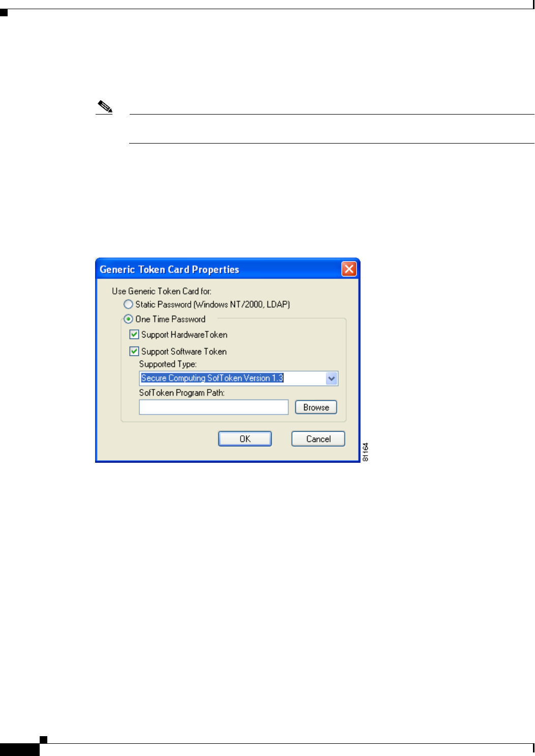
5-40
Cisco Aironet Wireless LAN Client Adapters Installation and Configuration Guide for Windows OL-1394-06
Chapter 5 Configuring the Client Adapter
Setting Network Security Parameters
Step 5 Make sure that the name of the certificate authority from which the server certificate was downloaded
appears in the Trusted root certificate authority (CA) field. If necessary, click the arrow on the
drop-down menu and select the appropriate name.
Note If you leave this field blank, you are prompted to accept a connection to the root certification
authority during the authentication process.
Step 6 Check the Connect only if server is signed by specified trusted root CA check box if you want to
ensure that the certificate server uses the trusted root certificate specified in the field above. This
prevents the client from establishing connections to rogue access points.
Step 7 Currently Generic Token Card is the only second phase EAP type available. Click Properties. The
Generic Token Card Properties screen appears (see Figure 5-11).
Figure 5-11 Generic Token Card Properties Screen
Step 8 Select either the Static Password (Windows NT/2000, LDAP) or the One Time Password option,
depending on your user database.
Step 9 Perform one of the following:
•If you selected the Static Password (Windows NT/2000, LDAP) option in Step 8, go to Step 10.
•If you selected the One Time Password option in Step 8, check one or both of the following check
boxes to specify the type of tokens that will be supported for one-time passwords:
–
Support Hardware Token—A hardware token device obtains the one-time password. You
must use your hardware token device to obtain the one-time password and enter the password
when prompted for your user credentials.
–
Support Software Token—The PEAP supplicant works with a software token program to
retrieve the one-time password. You have to enter only the PIN, not the one-time password. If
you check this check box, you must also select from the Supported Type drop-down box the
software token software that is installed on the client (such as Secure Computing SofToken
Version 1.3, Secure Computing SofToken II 2.0, or RSA SecurID Software Token v 2.5), and if
Secure Computing SofToken Version 1.3 is selected, you must locate the software program path
using the Browse button.
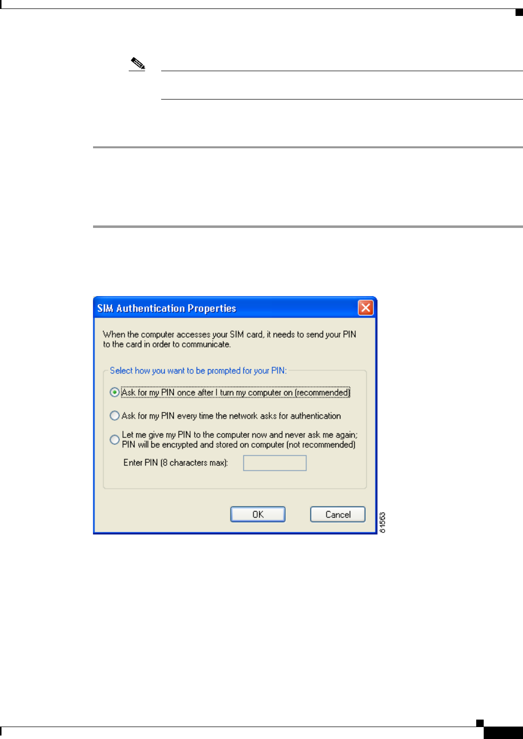
5-41
Cisco Aironet Wireless LAN Client Adapters Installation and Configuration Guide for Windows
OL-1394-06
Chapter 5 Configuring the Client Adapter Setting Network Security Parameters
Note The SofToken Program Path field is unavailable if a software token program other than
Secure Computing SofToken Version 1.3 is selected.
Step 10 Click OK three times to save your settings. The configuration is complete.
Step 11 Refer to Chapter 6 for instructions on authenticating using PEAP.
Enabling EAP-SIM
Follow the steps below to enable EAP-SIM.
Step 1 For EAP type, select SIM Authentication.
Step 2 Click Properties. The SIM Authentication Properties screen appears (see Figure 5-12).
Figure 5-12 SIM Authentication Properties Screen
Step 3 To access any resources (data or commands) on the SIM, the EAP-SIM supplicant must provide a valid
PIN to the SIM card, which must match the PIN stored on the SIM. Select one of the following options
to specify how the EAP-SIM supplicant should handle the SIM card’s PIN:
•Ask for my PIN once after I turn my computer on (recommended)—The software does not
permanently store the PIN. It prompts you for the PIN once, on the first authentication of every
session, where a session is defined as the time between power-up and shutdown or reboot.
•Ask for my PIN every time the network asks for authentication—The software never stores the
PIN; it prompts you for the PIN every time an EAP-SIM authentication is performed. This option is
not recommended if your client will be roaming between access points or if session timeouts are
implemented (such as for accounting and security purposes).

5-42
Cisco Aironet Wireless LAN Client Adapters Installation and Configuration Guide for Windows OL-1394-06
Chapter 5 Configuring the Client Adapter
Setting Network Security Parameters
•Let me give my PIN to the computer now and never ask me again; PIN will be encrypted and
stored on computer (not recommended)—You need to enter the PIN only once, in the Enter PIN
edit box below this option. The software stores the PIN in the registry and retrieves it from there
when required. If you select this option, you must enter the PIN now. The PIN is validated when an
authentication attempt is made.
Note This option is not recommended because it enables others to use the SIM without knowing
the PIN.
Step 4 Click OK twice to save your settings. The configuration is complete.
Step 5 If you are prompted to restart your client adapter, turn off your client adapter’s radio, wait a few seconds,
and then turn the radio back on. Refer to the “Turning Your Client Adapter’s Radio On or Off” section
on page 9-15 for instructions.
Step 6 Refer to Chapter 6 for instructions on authenticating using EAP-SIM.
Disabling LEAP or Host-Based EAP
If you ever need to disable LEAP or host-based EAP for a particular profile, follow the instructions
below for your EAP authentication type.
Disabling LEAP
To disable LEAP for a particular profile, select None from the Network Security Type drop-down box
on the Network Security screen in ACU, click OK, and click OK or Apply on the Profile Manager
screen.
Disabling Host-Based EAP
To disable host-based EAP (EAP-TLS, PEAP, or EAP-SIM) for a particular profile, follow the steps
below:
Step 1 Select None from the Network Security Type drop-down box on the Network Security screen in ACU
and click OK.
Step 2 Click OK or Apply on the Profile Manager screen.
Step 3 Perform one of the following, depending on your computer’s operating system:
•If your computer is running Windows 98, 98 SE, NT, or Me, run the Microsoft 802.1X
Authentication Client application. Then go to Step 5.
•If your computer is running Windows 2000, double-click My Computer, Control Panel, and
Network and Dial-up Connections. Right-click Local Area Connection. Click Properties. The
Local Area Connection Properties screen appears.
•If your computer is running Windows XP, double-click My Computer,Control Panel, and
Network Connections. Right-click Wireless Network Connection. Click Properties. The
Wireless Network Connection Properties screen appears.

5-43
Cisco Aironet Wireless LAN Client Adapters Installation and Configuration Guide for Windows
OL-1394-06
Chapter 5 Configuring the Client Adapter Setting Network Security Parameters
Step 4 Click the Authentication tab.
Note In Service Pack 1 for Windows XP, the Authentication tab has moved from its previous location.
To access it, click the Wireless Networks tab, select the network that you are configuring in the
Preferred network list, and click Properties.
Step 5 Uncheck the Enable network access control using IEEE 802.1X check box.
Step 6 Click OK.

5-44
Cisco Aironet Wireless LAN Client Adapters Installation and Configuration Guide for Windows OL-1394-06
Chapter 5 Configuring the Client Adapter
Setting Network Security Parameters

CHAPTER
6-1
Cisco Aironet Wireless LAN Client Adapters Installation and Configuration Guide for Windows
OL-1394-06
6
Using EAP Authentication
This chapter explains the sequence of events that occurs and the actions you must take when a profile
that is set for EAP authentication is selected for use.
The following topics are covered in this chapter:
•Overview, page 6-2
•Using LEAP, page 6-2
•Using LEAP with the Windows Username and Password, page 6-3
•Using LEAP with an Automatically Prompted Login, page 6-6
•Using LEAP with a Manually Prompted Login, page 6-9
•Using LEAP with a Saved Username and Password, page 6-13
•Using EAP-TLS, page 6-15
•Using PEAP, page 6-16
•Using EAP-SIM, page 6-19
•Restarting the Authentication Process, page 6-21
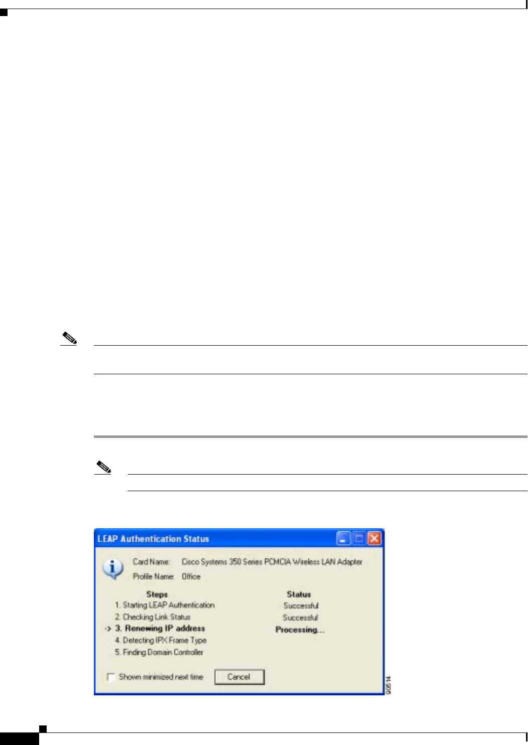
6-2
Cisco Aironet Wireless LAN Client Adapters Installation and Configuration Guide for Windows OL-1394-06
Chapter 6 Using EAP Authentication
Overview
Overview
This chapter explains the sequence of events that occurs as soon as you or ACU’s auto profile selection
feature selects a profile that uses EAP authentication as well as after you eject and reinsert the client
adapter, reboot the computer, log on while this profile is selected, or are informed that your username
and password have expired. The chapter contains seven sections based on the profile’s authentication
type and its username and password settings:
•LEAP with the Windows username and password, page 6-3
•LEAP with an automatically prompted login, page 6-6
•LEAP with a manually prompted login, page 6-9
•LEAP with a saved username and password, page 6-13
•EAP-TLS, page 6-15
•PEAP, page 6-16
•EAP-SIM, page 6-19
Also provided are an overview of LEAP (below) and instructions for restarting the authentication
process when necessary (page 6-21).
Follow the instructions for your profile’s authentication type and credential settings to successfully
authenticate.
Note If any error messages appear during authentication, refer to Chapter 10 for explanations and
recommended actions.
Using LEAP
Step 1 When LEAP authentication begins, the LEAP Authentication Status screen appears (see Figure 6-1).
Note The LEAP Authentication Status screen might appear behind any open applications.
Figure 6-1 LEAP Authentication Status Screen

6-3
Cisco Aironet Wireless LAN Client Adapters Installation and Configuration Guide for Windows
OL-1394-06
Chapter 6 Using EAP Authentication Using LEAP with the Windows Username and Password
This screen provides information about the status of LEAP authentication. Table 6-1 lists and explains
the stages of LEAP authentication. As each stage is completed, a status message (such as Successful)
appears in the Status field. If any error messages appear, refer to the “LEAP Authentication Error
Messages” section on page 10-18 for an explanation and the recommended action to take.
Step 2 If you do not want the LEAP Authentication Status screen to appear each time the client adapter attempts
to LEAP authenticate, check the Shown minimized next time check box in the bottom left corner of the
screen. On future LEAP authentication attempts, the LEAP Authentication Status screen appears
minimized in the Windows system tray.
Note To make the LEAP Authentication Status screen reappear once it has been minimized, click the
LEAP Authentication Status tab in the Windows system tray and uncheck the Shown
minimized next time check box. The LEAP Authentication Status screen should now appear for
all future LEAP authentication attempts.
Using LEAP with the Windows Username and Password
After Profile Selection or Card Insertion
After you (or auto profile selection) select a profile that uses LEAP authentication and specifies that your
Windows username and password also serve as your LEAP username and password or you eject and
reinsert the client adapter while this profile is selected, the following events occur:
1. The LEAP Authentication Status screen appears.
2. If your client adapter authenticates, the screen shows that each stage was successful and then
disappears. ACM now shows Authenticated, and the Server Based Authentication field on the ACU
Status screen shows LEAP Authenticated.
Table 6-1 Stages of LEAP Authentication
Stage Explanation
Starting LEAP Authentication The client adapter associates to an access point, and the LEAP
authentication process begins.
Checking Link Status The client adapter is LEAP authenticated, and the network
connection is verified.
Renewing IP Address If DHCP is enabled, the IP address is released and renewed.
Detecting IPX Frame Type On Windows 2000 and XP, the IPX frame type is reset if
AutoDetect is enabled.
Finding Domain Controller If you are logging into a domain and the active profile
specifies that the domain name be included, an attempt is
made to find the domain controller to make sure subsequent
access to the domain is successful.
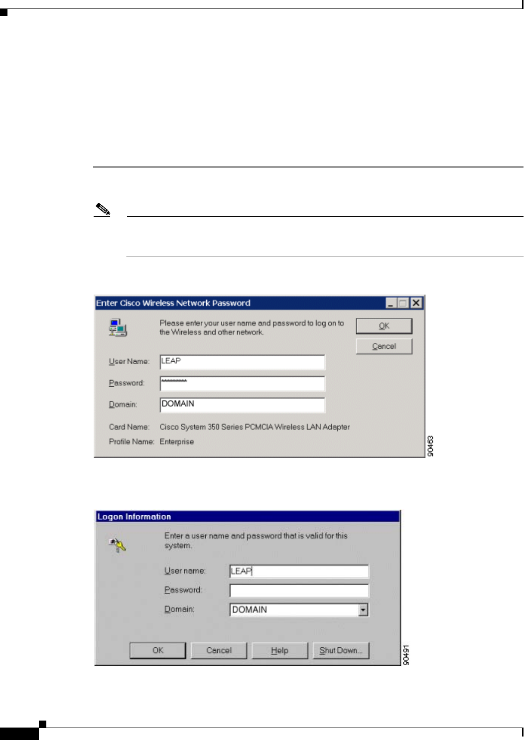
6-4
Cisco Aironet Wireless LAN Client Adapters Installation and Configuration Guide for Windows OL-1394-06
Chapter 6 Using EAP Authentication
Using LEAP with the Windows Username and Password
If the authentication attempt fails, an error message appears after the LEAP timeout period has
expired. Refer to the “LEAP Authentication Error Messages” section on page 10-18 for the
necessary action to take.
After a Reboot or Logon
After your computer reboots or you log on, follow the steps below to LEAP authenticate.
Step 1 When the Windows login screen appears (see Figure 6-2 and Figure 6-3), enter your Windows username
and password and click OK. The domain name is optional.
Note If your computer is running Windows NT, 2000, or XP and has Novell Client 32 software
installed, a separate LEAP login screen appears before the Novell login screen. If this occurs,
enter your Windows and Novell username and password in the login screens and click OK.
Figure 6-2 Windows Login Screen (Windows 98, 98 SE, and Me)
Figure 6-3 Windows Login Screen (Windows NT)

6-5
Cisco Aironet Wireless LAN Client Adapters Installation and Configuration Guide for Windows
OL-1394-06
Chapter 6 Using EAP Authentication Using LEAP with the Windows Username and Password
Note The Windows login screens shown above appear on computers running Windows 98, 98 SE, and
Me (Figure 6-2) and Windows NT (Figure 6-3), respectively. The login screen looks slightly
different on computers running Windows 2000 and XP.
The LEAP Authentication Status screen appears.
Step 2 If your client adapter authenticates, the screen shows that each stage was successful and then disappears.
ACM now shows Authenticated, and the Server Based Authentication field on the ACU Status screen
shows LEAP Authenticated.
If the authentication attempt fails, an error message appears after the LEAP timeout period has expired.
Refer to the “LEAP Authentication Error Messages” section on page 10-18 for the necessary action to
take.
Step 3 Windows continues to log you onto the system.
After Your LEAP Credentials Expire
If the LEAP credentials (username and password) for your current profile expire or become invalid,
follow the steps below to reauthenticate.
Note If your computer is running Windows NT, 2000, or XP and you change your Windows password using
the standard Windows Change Password function, the client updates the LEAP password automatically
and maintains its connection to the access point if the current profile uses the Windows username and
password. If your computer is running Windows 98, 98 SE, or Me and you change your Windows
password, the client loses association from the access point, and you are prompted to enter your new
credentials.
Step 1 Click OK when the following message appears: “The user name and password entered are no longer valid
and have failed the LEAP authentication process. Please enter a new user name and password.”
Step 2 When the Windows login screen appears, enter your new username and password and click OK. The
client adapter should authenticate using your new credentials.
Note If you click Cancel rather than OK on the Windows login screen, the following message appears:
“The profile will be disabled until you select the Reauthenticate option, Windows restarts, or the
card is ejected and reinserted. Are you sure?” If you click No, the Windows login screen
reappears and allows you to enter your new credentials. If you click Yes, the current profile is
disabled until you select Reauthenticate from ACM or the Commands drop-down menu in ACU,
reboot your computer, or eject and reinsert the card. The Current Profile field on the ACU Status
screen lists the profile as being Disabled.
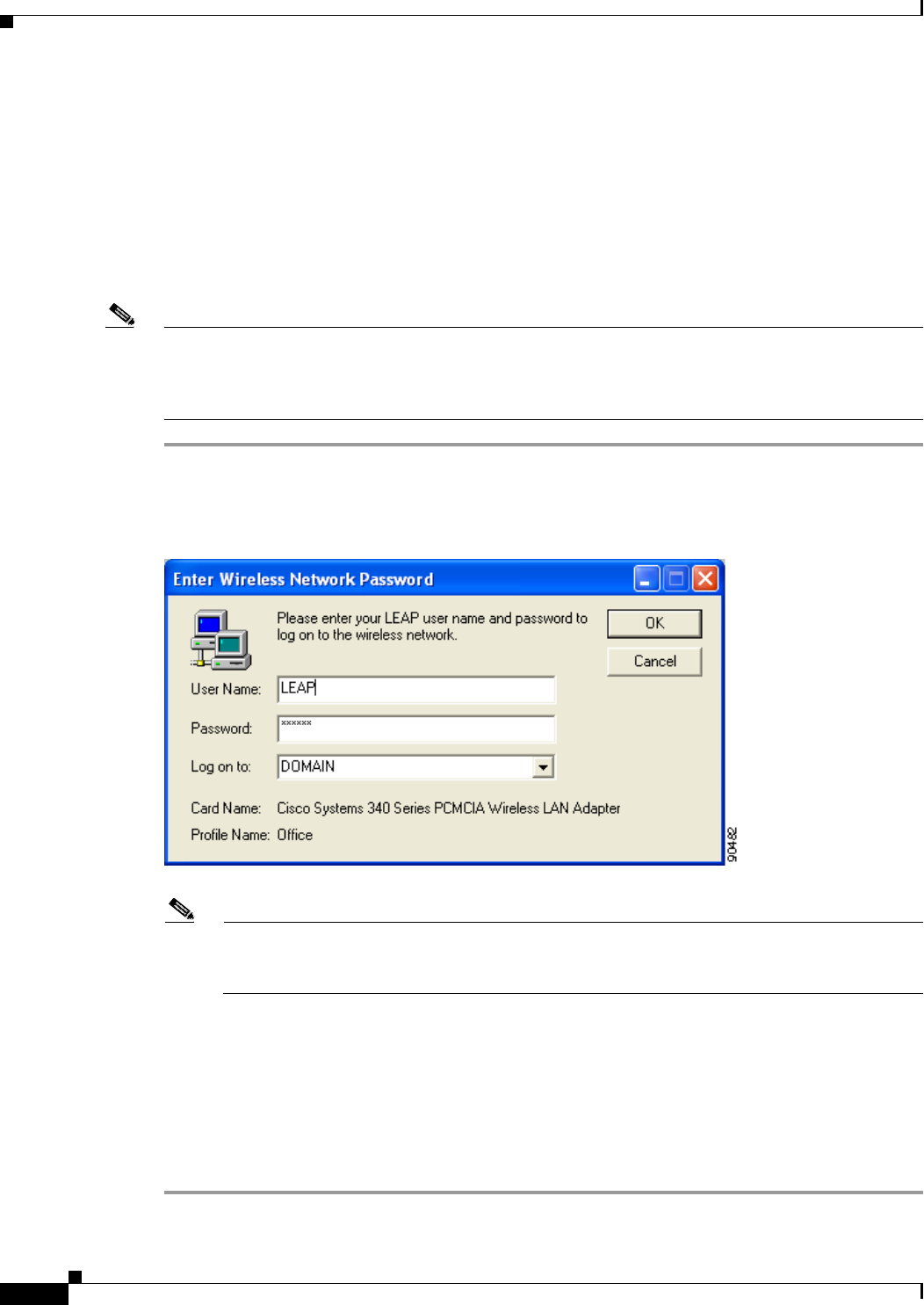
6-6
Cisco Aironet Wireless LAN Client Adapters Installation and Configuration Guide for Windows OL-1394-06
Chapter 6 Using EAP Authentication
Using LEAP with an Automatically Prompted Login
Using LEAP with an Automatically Prompted Login
After Profile Selection or Card Insertion
After you (or auto profile selection) select a profile that uses LEAP authentication but specifies that you
be automatically prompted to enter a separate LEAP username and password or you eject and reinsert
the client adapter while this profile is selected, follow the steps below to LEAP authenticate.
Note This procedure is applicable the first time an automatically prompted LEAP profile is selected. After you
follow the steps below to enter your LEAP credentials, you can switch profiles without having to re-enter
your credentials until you reboot your computer, eject and reinsert your client adapter, or change the
profile in any way (including its priority in auto profile selection).
Step 1 When the LEAP login screen appears (see Figure 6-4), enter your LEAP username and password and
click OK. The domain name is optional.
Figure 6-4 LEAP Login Screen
Note The LEAP login screen shown above appears on computers running Windows NT, 2000, or XP.
The LEAP login screen looks slightly different on computers running other Windows operating
systems.
The LEAP Authentication Status screen appears.
Step 2 If your client adapter authenticates, the screen shows that each stage was successful and then disappears.
ACM now shows Authenticated, and the Server Based Authentication field on the ACU Status screen
shows LEAP Authenticated.
If the authentication attempt fails, an error message appears after the LEAP timeout period has expired.
Refer to the “LEAP Authentication Error Messages” section on page 10-18 for the necessary action to
take.
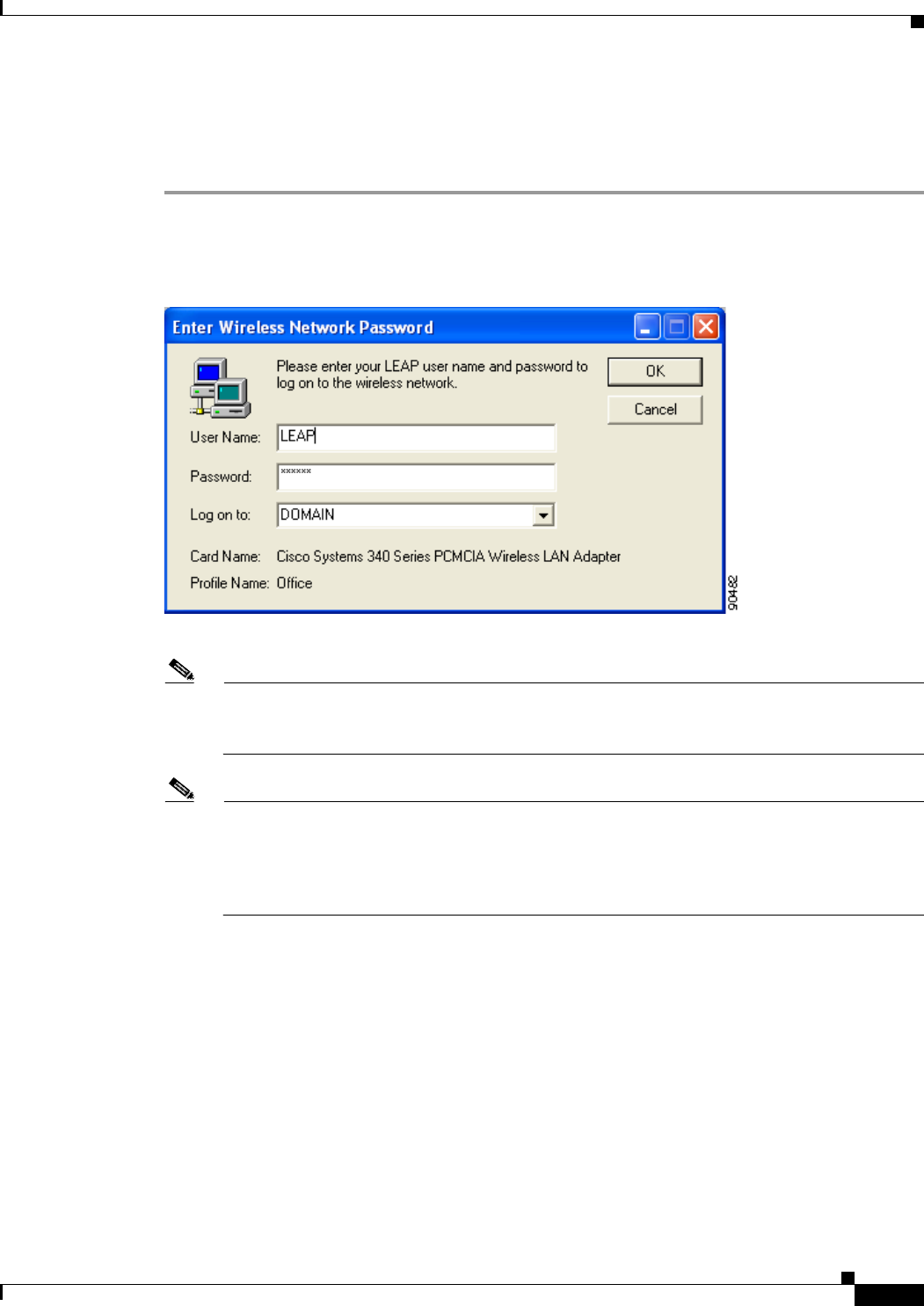
6-7
Cisco Aironet Wireless LAN Client Adapters Installation and Configuration Guide for Windows
OL-1394-06
Chapter 6 Using EAP Authentication Using LEAP with an Automatically Prompted Login
After a Reboot or Logon
After your computer reboots or you log on, follow the steps below to LEAP authenticate.
Step 1 When the LEAP login screen appears (see Figure 6-5), enter your LEAP username and password and
click OK. The domain name is optional.
Figure 6-5 LEAP Login Screen
Note The LEAP login screen shown above appears on computers running Windows NT, 2000, or XP.
The LEAP login screen looks slightly different on computers running other Windows operating
systems.
Note The LEAP login screen should appear before the Windows login screen on computers running
Windows 98, 98 SE, or Me. If the Windows screen appears first, follow the instructions in the
“LEAP Login Screen Does Not Appear Before Windows Login Screen (Windows 98, 98 SE, and
Me Only)” section on page 10-13. On computers running Windows NT, 2000, or XP, the LEAP
login screen appears after the Windows login screen.
The LEAP Authentication Status screen appears.
Step 2 If your client adapter authenticates, the screen shows that each stage was successful and then disappears.
ACM now shows Authenticated, and the Server Based Authentication field on the ACU Status screen
shows LEAP Authenticated.
If the authentication attempt fails, an error message appears after the LEAP timeout period has expired.
Refer to the “LEAP Authentication Error Messages” section on page 10-18 for the necessary action to
take.
Step 3 When the network login screen appears (see Figure 6-6 and Figure 6-7), enter your network username
and password and click OK.
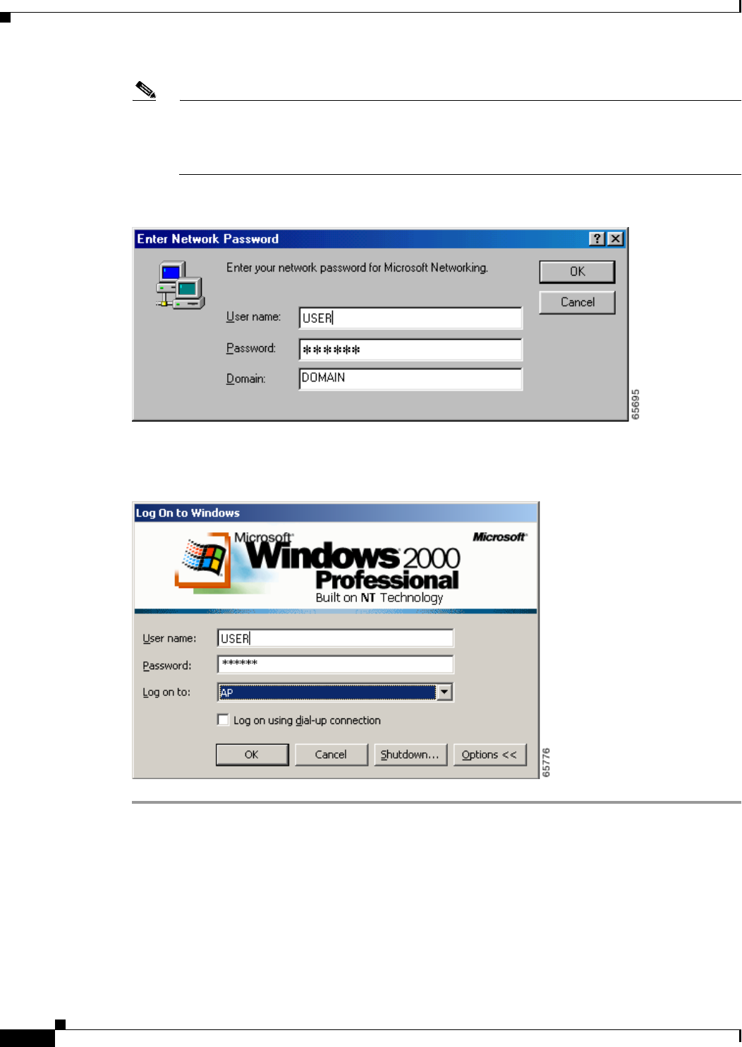
6-8
Cisco Aironet Wireless LAN Client Adapters Installation and Configuration Guide for Windows OL-1394-06
Chapter 6 Using EAP Authentication
Using LEAP with an Automatically Prompted Login
Note Figure 6-6 shows an example network login screen that may appear on computers running
Windows 98, 98 SE, and Me. Your screen may look different. Figure 6-7 shows the network
login screen that appears on Windows 2000 systems. The login screen looks slightly different on
computers running Windows NT and XP.
Figure 6-6 Network Login Screen (Windows 98, 98 SE, and Me)
Figure 6-7 Network Login Screen (Windows 2000)

6-9
Cisco Aironet Wireless LAN Client Adapters Installation and Configuration Guide for Windows
OL-1394-06
Chapter 6 Using EAP Authentication Using LEAP with a Manually Prompted Login
After Your LEAP Credentials Expire
If the LEAP credentials (username and password) for your current profile expire or become invalid,
follow the steps below to reauthenticate.
Step 1 Click OK when the following message appears: “The user name and password entered are no longer valid
and have failed the LEAP authentication process. Please enter a new user name and password.”
Step 2 When the LEAP login screen appears, enter your new username and password and click OK. The client
adapter should authenticate using your new credentials.
Note If you click Cancel rather than OK on the LEAP login screen, the following message appears:
“The profile will be disabled until you select the Reauthenticate option, Windows restarts, or the
card is ejected and reinserted. Are you sure?” If you click No, the LEAP login screen reappears
and allows you to enter your new credentials. If you click Yes, the current profile is disabled until
you select Reauthenticate from ACM or the Commands drop-down menu in ACU, reboot your
computer, or eject and reinsert the card. The Current Profile field on the ACU Status screen lists
the profile as being Disabled.
Using LEAP with a Manually Prompted Login
After Profile Selection
After you (or auto profile selection) select a profile that uses LEAP authentication but specifies that the
process be manually invoked, follow the steps below to LEAP authenticate.
Note This procedure is applicable the first time a manual LEAP profile is selected. After you follow the steps
below to enter your LEAP credentials, you can switch profiles without having to re-enter your
credentials until you reboot your computer, eject and reinsert your client adapter, or change the profile
in any way (including its priority in auto profile selection).
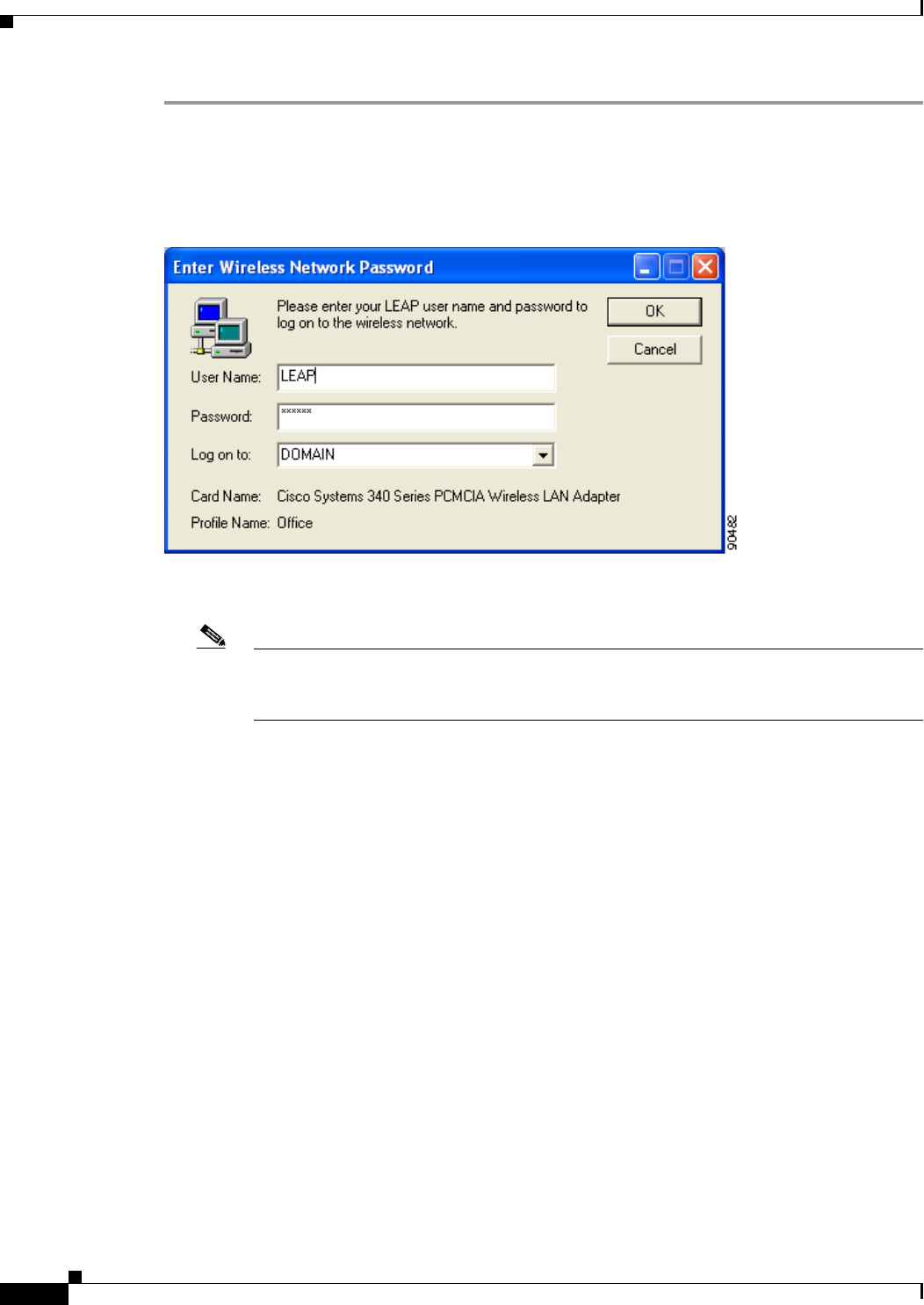
6-10
Cisco Aironet Wireless LAN Client Adapters Installation and Configuration Guide for Windows OL-1394-06
Chapter 6 Using EAP Authentication
Using LEAP with a Manually Prompted Login
Step 1 Perform one of the following:
•If you select a manual LEAP profile from the Use Selected Profile drop-down box, the LEAP login
screen appears (see Figure 6-8).
Figure 6-8 LEAP Login Screen
Enter your LEAP username and password and click OK. The domain name is optional.
Note The LEAP login screen shown above appears on computers running Windows NT, 2000, or
XP. The LEAP login screen looks slightly different on computers running other Windows
operating systems.
•If auto profile selection selects a manual LEAP profile, you must select the Manual LEAP Login
option from the Commands drop-down menu (see Figure 6-9).
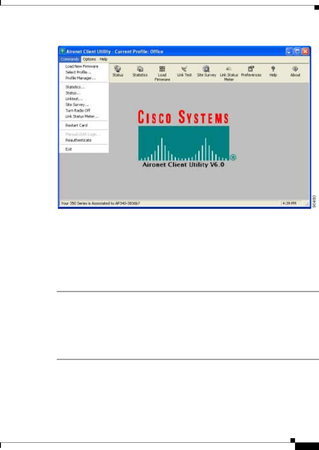
6-11
Cisco Aironet Wireless LAN Client Adapters Installation and Configuration Guide for Windows
OL-1394-06
Chapter 6 Using EAP Authentication Using LEAP with a Manually Prompted Login
Figure 6-9 Commands Drop-Down Menu
When the LEAP login screen appears (see Figure 6-8), enter your LEAP username and password
and click OK. The domain name is optional.
Step 2 The LEAP Authentication Status screen appears. If your client adapter authenticates, the screen shows
that each stage was successful and then disappears. ACM now shows Authenticated, and the Server
Based Authentication field on the ACU Status screen shows LEAP Authenticated.
If the authentication attempt fails, an error message appears after the LEAP timeout period has expired.
Refer to the “LEAP Authentication Error Messages” section on page 10-18 for the necessary action to
take.
After a Reboot, Logon, or Card Insertion
After your computer reboots, you log on, or you eject and reinsert the client adapter, the adapter does
not automatically attempt to authenticate. You must manually invoke the authentication process. To do
so, follow the steps below.
Step 1 If you rebooted your computer or logged on, complete your standard Windows login.
Step 2 Open ACU.
Step 3 Select the Manual LEAP Login option from the Commands drop-down menu (see Figure 6-10).
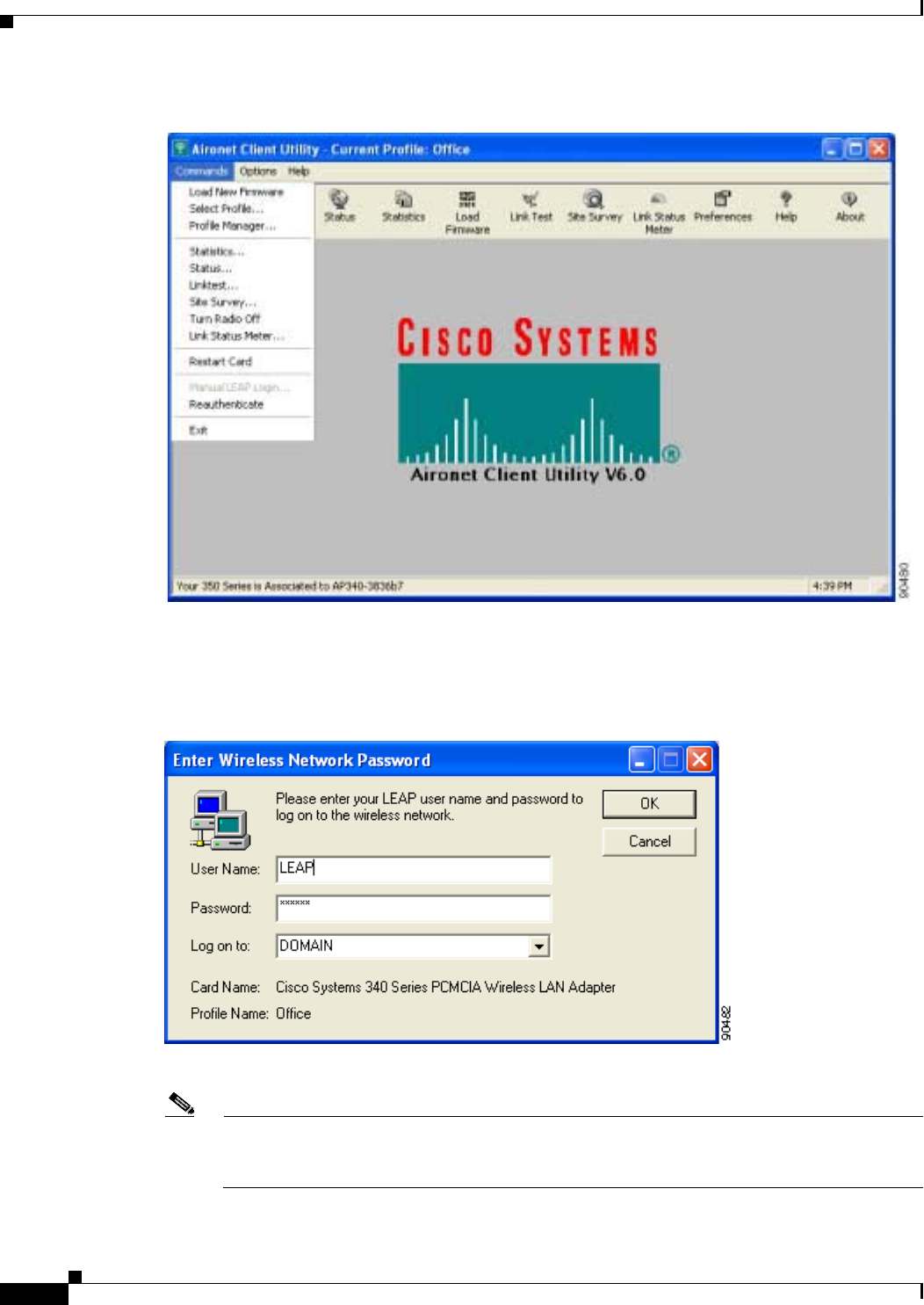
6-12
Cisco Aironet Wireless LAN Client Adapters Installation and Configuration Guide for Windows OL-1394-06
Chapter 6 Using EAP Authentication
Using LEAP with a Manually Prompted Login
Figure 6-10 Commands Drop-Down Menu
Step 4 When the LEAP login screen appears (see Figure 6-11), enter your LEAP username and password and
click OK. The domain name is optional.
Figure 6-11 LEAP Login Screen
Note The LEAP login screen shown above appears on computers running Windows NT, 2000, or XP.
The LEAP login screen looks slightly different on computers running other Windows operating
systems.

6-13
Cisco Aironet Wireless LAN Client Adapters Installation and Configuration Guide for Windows
OL-1394-06
Chapter 6 Using EAP Authentication Using LEAP with a Saved Username and Password
The LEAP Authentication Status screen appears.
Step 5 If your client adapter authenticates, the screen shows that each stage was successful and then disappears.
ACM now shows Authenticated, and the Server Based Authentication field on the ACU Status screen
shows LEAP Authenticated.
If the authentication attempt fails, an error message appears after the LEAP timeout period has expired.
Refer to the “LEAP Authentication Error Messages” section on page 10-18 for the necessary action to
take.
After Your LEAP Credentials Expire
If the LEAP credentials (username and password) for your current profile expire or become invalid,
follow the steps below to reauthenticate.
Step 1 Click OK when the following message appears: “The user name and password entered are no longer valid
and have failed the LEAP authentication process. Please enter a new user name and password.”
Step 2 When the LEAP login screen appears, enter your new username and password and click OK. The client
adapter should authenticate using your new credentials.
Note If you click Cancel rather than OK on the LEAP login screen, the following message appears:
“The profile will be disabled until you select the Reauthenticate option, Windows restarts, or the
card is ejected and reinserted. Are you sure?” If you click No, the LEAP login screen reappears
and allows you to enter your new credentials. If you click Yes, the current profile is disabled until
you select Reauthenticate from ACM or the Commands drop-down menu in ACU, reboot your
computer, or eject and reinsert the card. The Current Profile field on the ACU Status screen lists
the profile as being Disabled.
Using LEAP with a Saved Username and Password
After Profile Selection or Card Insertion
After you (or auto profile selection) select a profile that uses LEAP authentication with a saved LEAP
username and password or you eject and reinsert the client adapter while this profile is selected, the
following events occur:
1. The LEAP Authentication Status screen appears.
2. If your client adapter authenticates, the screen shows that each stage was successful and then
disappears. ACM now shows Authenticated, and the Server Based Authentication field on the ACU
Status screen shows LEAP Authenticated.
If the authentication attempt fails, an error message appears after the LEAP timeout period has
expired. Refer to the “LEAP Authentication Error Messages” section on page 10-18 for the
necessary action to take.

6-14
Cisco Aironet Wireless LAN Client Adapters Installation and Configuration Guide for Windows OL-1394-06
Chapter 6 Using EAP Authentication
Using LEAP with a Saved Username and Password
After a Reboot or Logon
After your computer reboots or you log on, the following events occur:
1. After you enter your Windows username and password, the LEAP authentication process begins
automatically using your saved LEAP username and password.
Note If you unchecked the No Network Connection Unless User Is Logged In check box on the
LEAP Settings screen, the LEAP authentication process begins before the Windows login
screen appears.
2. If your client adapter authenticates, the screen shows that each stage was successful and then
disappears. ACM now shows Authenticated, and the Server Based Authentication field on the ACU
Status screen shows LEAP Authenticated.
If the authentication attempt fails, an error message appears after the LEAP timeout period has
expired. Refer to the “LEAP Authentication Error Messages” section on page 10-18 for the
necessary action to take.
3. Windows continues to log you onto the system.
After Your LEAP Credentials Expire
If the LEAP credentials (username and password) for your current profile expire or become invalid,
follow the steps below to reauthenticate.
Step 1 Click OK when the following message appears: “The saved user name and password entered for this profile
are no longer valid and have failed the LEAP authentication process. Please enter a new user name and
password. Remember to change them permanently in the profile using the ACU Profile Manager.”
Step 2 When the LEAP login screen appears, enter your new username and password and click OK. The client
adapter should authenticate using your new credentials.
Note If you click Cancel rather than OK on the LEAP login screen, the following message appears:
“The profile will be disabled until you select the Reauthenticate option, Windows restarts, or the
card is ejected and reinserted. Are you sure?” If you click No, the LEAP login screen reappears
and allows you to enter your new credentials. If you click Yes, the current profile is disabled until
you select Reauthenticate from ACM or the Commands drop-down menu in ACU, reboot your
computer, or eject and reinsert the card. The Current Profile field on the ACU Status screen lists
the profile as being Disabled.
Step 3 Edit the profile in ACU by changing the saved username and password on the LEAP Settings screen.
Step 4 Click OK three times to save the changes to your profile.

6-15
Cisco Aironet Wireless LAN Client Adapters Installation and Configuration Guide for Windows
OL-1394-06
Chapter 6 Using EAP Authentication Using EAP-TLS
Using EAP-TLS
After Profile Selection or Card Insertion
After you (or auto profile selection) select a profile that uses host-based EAP authentication and you
configure the card in Windows (provided Windows is using the Microsoft 802.1X supplicant) for
EAP-TLS authentication or you eject and reinsert the client adapter while this profile is selected, follow
the steps below to EAP authenticate.
Step 1 If your computer is running Windows XP and a pop-up message appears above the Windows system tray
informing you that you need to accept a certificate to begin the EAP authentication process, click the
message and follow the instructions provided to accept the certificate.
Note You should not have to accept a certificate for future authentication attempts. After you accept
one, the same certificate is used subsequently.
Step 2 If a message appears indicating the root certification authority for the server’s certificate, and it is the
correct certification authority, click OK to accept the connection. Otherwise, click Cancel.
Step 3 If a message appears indicating the server to which your client adapter is connected, and it is the correct
server to connect to, click OK to accept the connection. Otherwise, click Cancel.
Step 4 The client adapter should now EAP authenticate. To verify authentication, double-click My Computer,
Control Panel, and Network Connections. The status appears to the right of your Wireless Network
Connection. Click View and Refresh to obtain the current status. If the client adapter is authenticated,
the status reads Authentication succeeded.
After a Reboot or Logon
After your computer reboots or you log on using your Windows username and password, the EAP
authentication process begins automatically and the client adapter should EAP authenticate.
To verify authentication, double-click My Computer,Control Panel, and Network Connections. The
status appears to the right of your Wireless Network Connection. Click View and Refresh to obtain the
current status. If the client adapter is authenticated, the status reads Authentication succeeded.
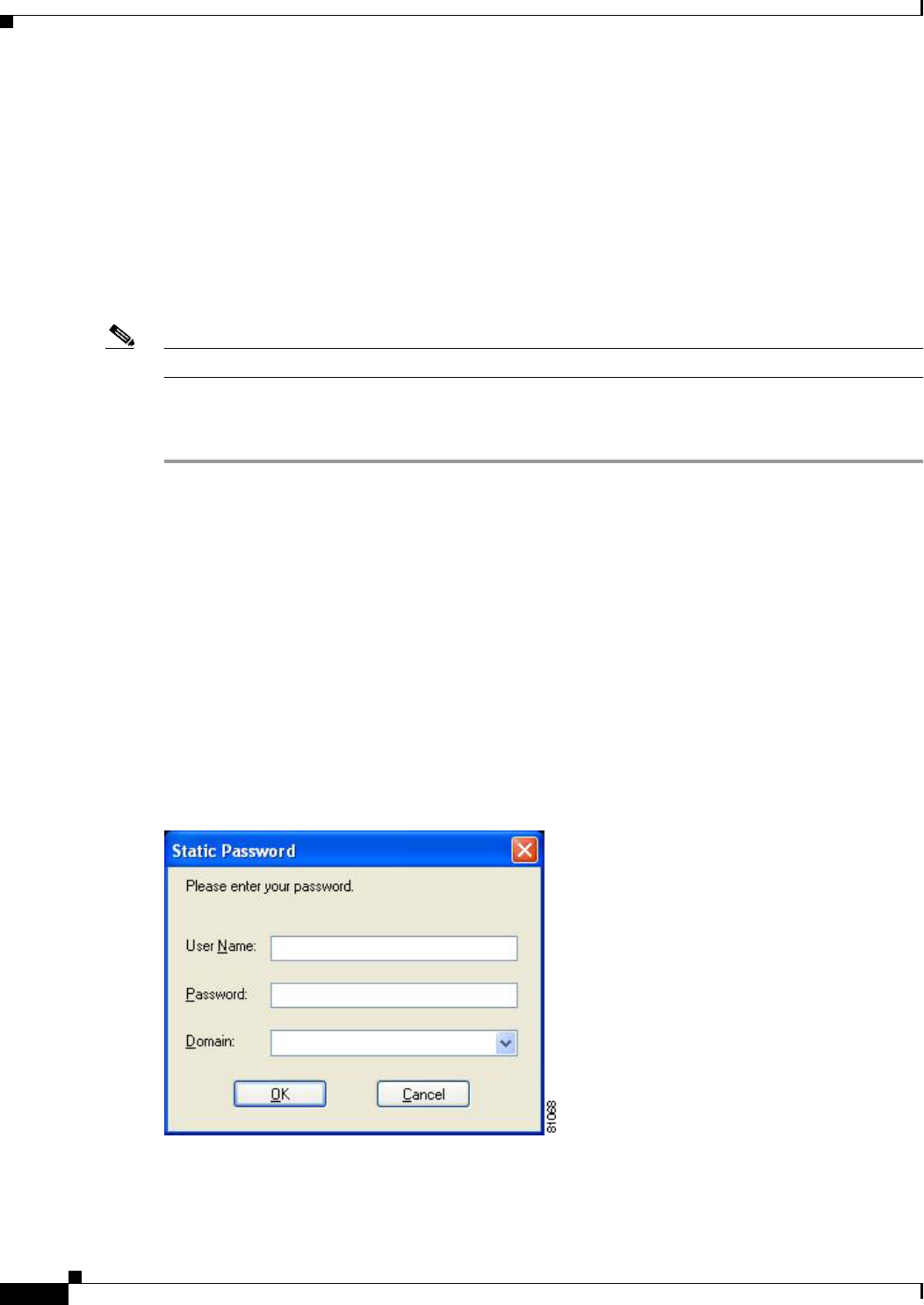
6-16
Cisco Aironet Wireless LAN Client Adapters Installation and Configuration Guide for Windows OL-1394-06
Chapter 6 Using EAP Authentication
Using PEAP
Using PEAP
After Profile Selection, Card Insertion, Reboot, or Logon
After you (or auto profile selection) select a profile that uses host-based EAP authentication and you
configure the card in Windows (provided Windows is using the Microsoft 802.1X supplicant) for PEAP
authentication, follow the steps in one of the sections below, depending on your user database, to EAP
authenticate.
Note These instructions are applicable after profile selection, card ejection and re-insertion, reboot, or logon.
Windows NT or 2000 Domain Databases or LDAP Databases Only
Step 1 If your computer is running Windows XP, a pop-up message appears above the Windows system tray
informing you that you need to select a certificate or other credentials to access the network. Click this
message.
Step 2 If a message appears indicating the root certification authority for the server’s certificate and it is the
correct certification authority, click OK to accept the connection. Otherwise, click Cancel.
Step 3 If a message appears indicating the server to which your client adapter is connected and it is the correct
server to connect to, click OK to accept the connection. Otherwise, click Cancel.
Step 4 Perform one of the following:
•If your computer is running Windows 2000, the Static Password screen appears (see Figure 6-12).
•If your computer is running Windows XP, a pop-up message appears above the Windows system tray
prompting you to process your logon information for your wireless network. Click this message. The
Static Password screen appears (see Figure 6-12).
Figure 6-12 Static Password Screen
Step 5 Enter your PEAP authentication username and password (which are registered with the RADIUS server).
Step 6 If applicable, select your domain name from the drop-down list or type it in.
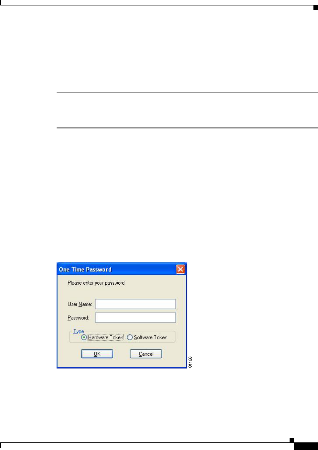
6-17
Cisco Aironet Wireless LAN Client Adapters Installation and Configuration Guide for Windows
OL-1394-06
Chapter 6 Using EAP Authentication Using PEAP
Step 7 Click OK. The client adapter should now EAP authenticate. To verify authentication, double-click My
Computer,Control Panel, and Network Connections. The status appears to the right of your Wireless
Network Connection. Click View and Refresh to obtain the current status. If the client adapter is
authenticated, the status reads Authentication succeeded.
Step 8 If you also have a locally cached Windows password, you must change it manually in Windows to
synchronize your passwords. To do so, press Ctrl-Alt-Delete, select Change Password, and enter your
old password once and your new password twice.
OTP Databases Only
Step 1 If your computer is running Windows XP, a pop-up message appears above the Windows system tray
informing you that you need to select a certificate or other credentials to access the network. Click this
message.
Step 2 If a message appears indicating the root certification authority for the server’s certificate and it is the
correct certification authority, click OK to accept the connection. Otherwise, click Cancel.
Step 3 If a message appears indicating the server to which your client adapter is connected and it is the correct
server to connect to, click OK to accept the connection. Otherwise, click Cancel.
Step 4 Perform one of the following:
•If your computer is running Windows 2000, the One Time Password screen appears (see
Figure 6-13).
•If your computer is running Windows XP, a pop-up message appears above the Windows system tray
prompting you to process your logon information for your wireless network. Click this message. The
One Time Password screen appears (see Figure 6-13).
Figure 6-13 One Time Password Screen
Step 5 Enter your PEAP authentication username in the User Name field.
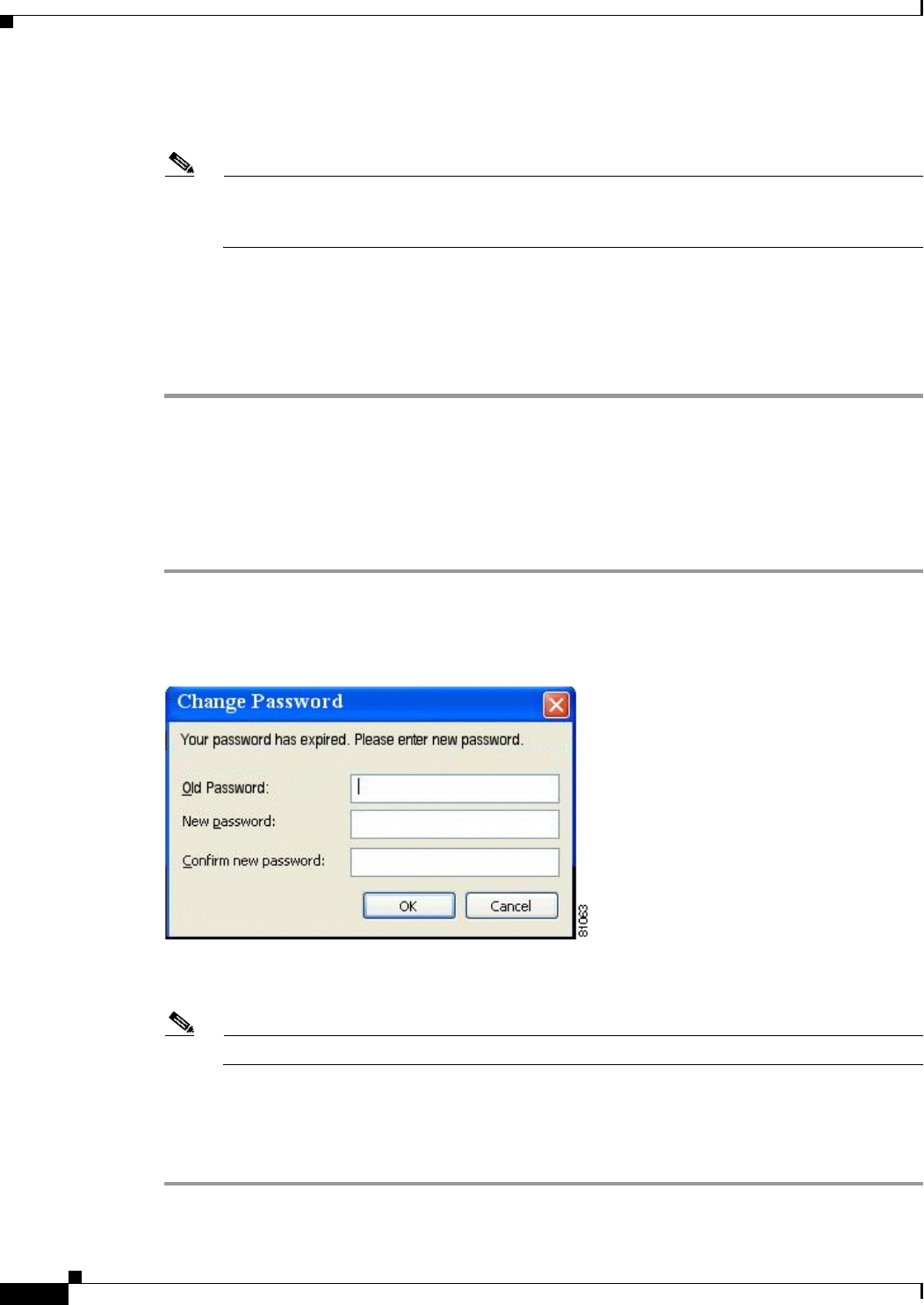
6-18
Cisco Aironet Wireless LAN Client Adapters Installation and Configuration Guide for Windows OL-1394-06
Chapter 6 Using EAP Authentication
Using PEAP
Step 6 Select either the Hardware Token or Software Token option. If you select the Software Token option,
the Password field on the One Time Password screen changes to the PIN field.
Note The Hardware Token and Software Token options are available only if you selected both of them
on the Generic Token Card Properties screen during configuration. Otherwise, only the option
you selected will be available.
Step 7 Enter either your hardware token password or your software token PIN.
Step 8 Click OK. The client adapter should now EAP authenticate. To verify authentication, double-click My
Computer,Control Panel, and Network Connections. The status appears to the right of your Wireless
Network Connection. Click View and Refresh to obtain the current status. If the client adapter is
authenticated, the status reads Authentication succeeded.
After Your Password Expires (Windows NT or 2000 Domain Databases Only)
If you are using a Windows NT or 2000 domain database with PEAP and the password for your current
user ID expires, follow the steps below to change your password.
Step 1 When the Change Password screen appears (see Figure 6-14) to indicate that your password has expired,
enter your old password in the Old Password field.
Figure 6-14 Change Password Screen
Step 2 Enter your new password in both the New Password and Confirm New Password fields.
Note The password is also changed in the Windows NT or 2000 domain user database.
Step 3 Click OK. The client adapter should authenticate using your new password. To verify authentication,
double-click My Computer,Control Panel, and Network Connections. The status appears to the right
of your Wireless Network Connection. Click View and Refresh to obtain the current status. If the client
adapter is authenticated, the status reads Authentication succeeded.
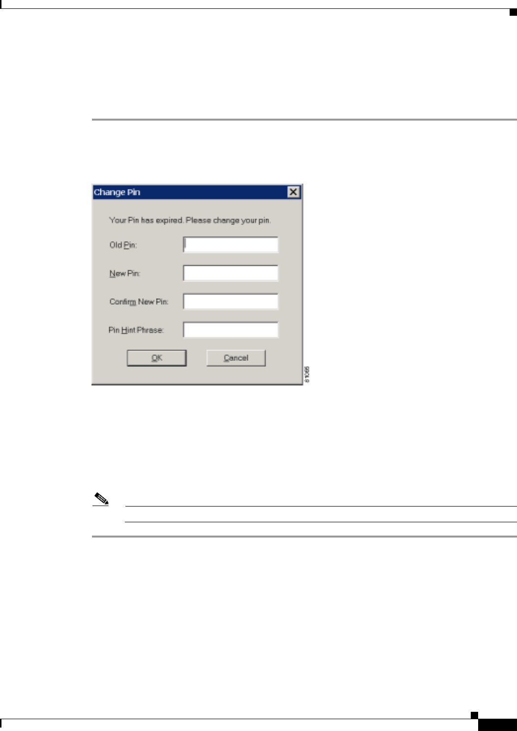
6-19
Cisco Aironet Wireless LAN Client Adapters Installation and Configuration Guide for Windows
OL-1394-06
Chapter 6 Using EAP Authentication Using EAP-SIM
After Your PIN Expires (OTP Databases Only)
If you are using an OTP database with PEAP and the PIN for your current user ID expires, follow the
steps below to change your PIN.
Step 1 When the Change PIN screen appears (see Figure 6-15) to indicate that your PIN has expired, enter your
old PIN in the Old PIN field.
Figure 6-15 Change PIN Screen
Step 2 Enter your new PIN in both the New PIN and Confirm New PIN fields.
Step 3 Enter a word that will help you to remember your PIN in the PIN Hint Phrase field.
Step 4 Click OK. The client adapter should authenticate using your new PIN. To verify authentication,
double-click My Computer,Control Panel, and Network Connections. The status appears to the right
of your Wireless Network Connection. Click View and Refresh to obtain the current status. If the client
adapter is authenticated, the status reads Authentication succeeded.
Note You should use the new PIN for future authentication attempts.
Using EAP-SIM
After you (or auto profile selection) select a profile that uses host-based EAP authentication and you
configure the card in Windows (provided Windows is using the Microsoft 802.1X supplicant) for
EAP-SIM authentication, the authentication process varies depending on the configuration option you
selected for the SIM card’s PIN.
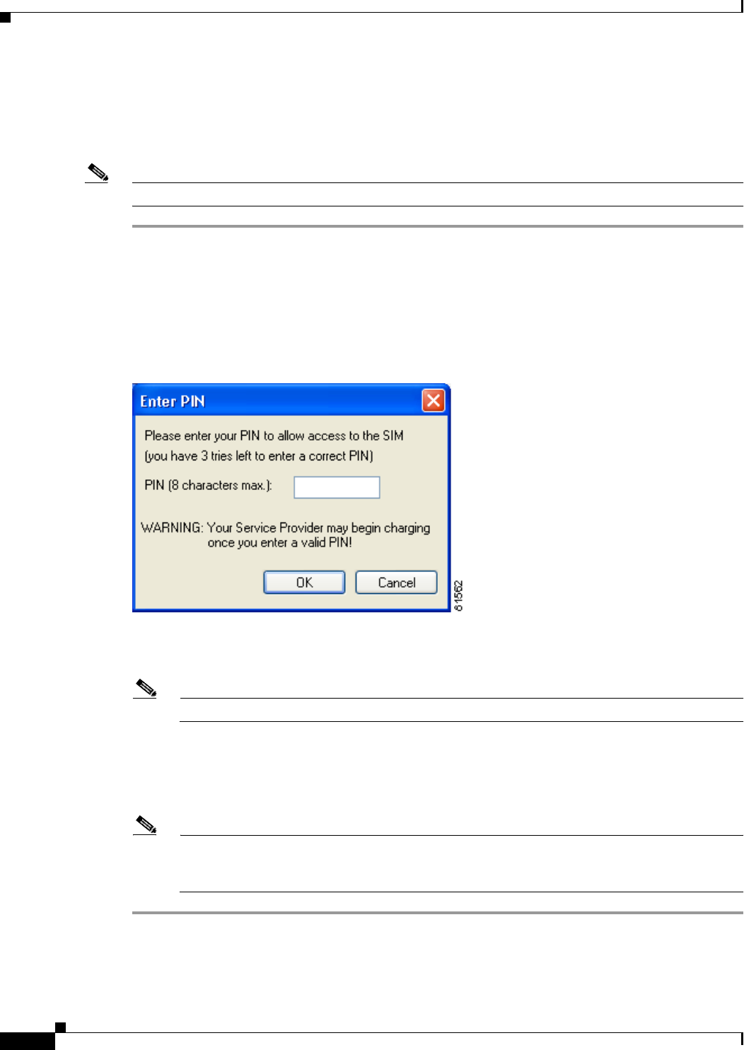
6-20
Cisco Aironet Wireless LAN Client Adapters Installation and Configuration Guide for Windows OL-1394-06
Chapter 6 Using EAP Authentication
Using EAP-SIM
If You Are Prompted for the PIN
If you chose to be prompted for the PIN after a power-up or reboot or at every authentication request,
follow the steps below to EAP authenticate.
Note These instructions are applicable after profile selection, card ejection and re-insertion, reboot, or logon.
Step 1 Perform one of the following:
•If your computer is running Windows 2000, the Enter PIN screen appears (see Figure 6-16).
•If your computer is running Windows XP, a pop-up message appears above the Windows system tray
informing you that you need to enter your credentials to access the network. Click this message. The
Enter PIN screen appears (see Figure 6-16).
Figure 6-16 Enter PIN Screen
Step 2 Enter your PIN and click OK. The computer now retrieves information from the SIM card. If you enter
the PIN incorrectly, an error message appears.
Note If you exceed the maximum number of retries for entering the PIN, the card locks up.
Step 3 The client adapter should now EAP authenticate. To verify authentication, double-click My Computer,
Control Panel, and Network Connections. The status appears to the right of your Wireless Network
Connection. Click View and Refresh to obtain the current status. If the client adapter is authenticated,
the status reads Authentication succeeded.
Note ACU and the Windows Wireless Network Connection icon in the Windows XP system tray may
indicate a connection status when authentication is still in the pending state or the authentication
server fails to respond.

6-21
Cisco Aironet Wireless LAN Client Adapters Installation and Configuration Guide for Windows
OL-1394-06
Chapter 6 Using EAP Authentication Restarting the Authentication Process
If the PIN Is Stored on the Computer
If you chose to store the PIN in the computer’s registry, the EAP authentication process begins
automatically, and the client adapter should EAP authenticate and use the saved PIN to access the SIM
card.
Note These instructions are applicable after profile selection, card ejection and re-insertion, reboot, or logon.
Note If the stored PIN is wrong and therefore rejected by the SIM, the EAP-SIM supplicant temporarily
changes the prompt mode to the default setting (Ask for my PIN once after I turn my computer on) in
order to prevent the SIM from locking up. Unless changed manually, this setting stays in effect until your
computer is powered off. Change your stored PIN on the SIM Authentication Properties screen.
To verify authentication, double-click My Computer,Control Panel, and Network Connections. The
status appears to the right of your Wireless Network Connection. Click View and Refresh to obtain the
current status. If the client adapter is authenticated, the status reads Authentication succeeded.
Note ACU and the Windows Wireless Network Connection icon in the Windows XP system tray may indicate
a connection status when authentication is still in the pending state or the authentication server fails to
respond.
Restarting the Authentication Process
If your client adapter was unable to authenticate using the specified username and password and you
have exhausted the retry limit (for example, LEAP tries only once to prevent you from being locked out
of the system), the current profile is disabled until you change the username or password, reboot your
computer, or eject and re-insert the client adapter. To force your client adapter to try to reauthenticate
using the username and password of the current profile, select Reauthenticate from ACM or the
Commands drop-down menu in ACU.

6-22
Cisco Aironet Wireless LAN Client Adapters Installation and Configuration Guide for Windows OL-1394-06
Chapter 6 Using EAP Authentication
Restarting the Authentication Process

CHAPTER
7-1
Cisco Aironet Wireless LAN Client Adapters Installation and Configuration Guide for Windows
OL-1394-06
7
Performing Diagnostics
This chapter explains how to use ACU to perform user-level diagnostics.
The following topics are covered in this chapter:
•Overview of ACU Diagnostic Tools, page 7-2
•Setting Parameters that Affect ACU Diagnostic Tools, page 7-3
•Viewing the Current Status of Your Client Adapter, page 7-4
•Viewing Statistics for Your Client Adapter, page 7-11
•Viewing the Link Status Meter, page 7-16
•Running an RF Link Test, page 7-17

7-2
Cisco Aironet Wireless LAN Client Adapters Installation and Configuration Guide for Windows OL-1394-06
Chapter 7 Performing Diagnostics
Overview of ACU Diagnostic Tools
Overview of ACU Diagnostic Tools
In addition to enabling you to configure your client adapter for use in various types of networks, ACU
provides tools that enable you to assess the performance of the client adapter and other devices on the
wireless network. ACU diagnostic tools perform the following functions:
•Display your client adapter’s current status and configured settings
•Display statistics pertaining to your client adapter’s transmission and reception of data
•Display a graphical image of your client adapter’s RF link
•Run an RF link test to assess the performance of the RF link between your client adapter and its
associated access point
Table 7-1 enables you to quickly locate instructions for using each of the diagnostic tools.
Table 7-1 Locating Diagnostic Instructions
Diagnostic Tool Page Number
Status 7-4
Statistics 7-11
Link status meter 7-16
RF link test 7-17
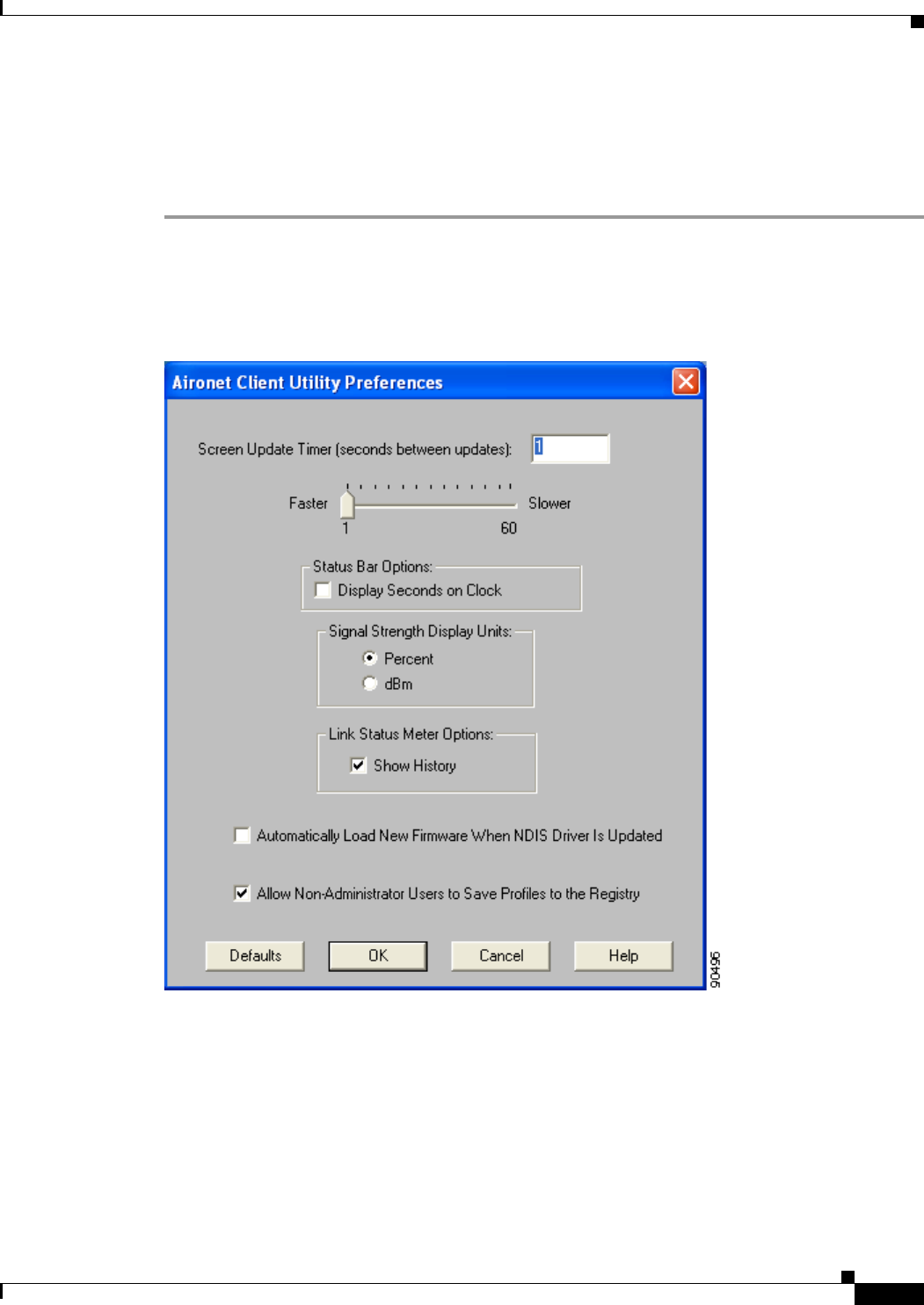
7-3
Cisco Aironet Wireless LAN Client Adapters Installation and Configuration Guide for Windows
OL-1394-06
Chapter 7 Performing Diagnostics Setting Parameters that Affect ACU Diagnostic Tools
Setting Parameters that Affect ACU Diagnostic Tools
Several parameters affect the operation of ACU diagnostic tools. Follow the steps below to set these
parameters.
Step 1 Open ACU.
Step 2 Click the Preferences icon or select Preferences from the Options drop-down menu. The Aironet Client
Utility Preferences screen appears (see Figure 7-1).
Figure 7-1 Aironet Client Utility Preferences Screen

7-4
Cisco Aironet Wireless LAN Client Adapters Installation and Configuration Guide for Windows OL-1394-06
Chapter 7 Performing Diagnostics
Viewing the Current Status of Your Client Adapter
Step 3 Table 7-2 lists and describes the parameters that affect the operation of ACU diagnostic tools. Follow
the instructions in the table to change any parameters.
Step 4 Click OK to save your changes.
Viewing the Current Status of Your Client Adapter
ACU enables you to view the current status of your client adapter as well as many of the settings that
have been configured for the adapter.
To view your client adapter’s status and settings, open ACU; then click the Status icon or select Status
from the Commands drop-down menu. The Status screen appears. Figure 7-2 shows the Status screen
with the signal strength values displayed as percentages, and Figure 7-3 shows the bottom of the same
screen with the signal strength values displayed in decibels with respect to milliwatts (dBm).
Note The name of the current profile appears in parentheses at the top of the screen.
Table 7-2 Parameters Affecting ACU Diagnostic Tools
Parameter Description
Screen Update Timer
(seconds between updates) Specifies how often the Status and Statistics screens are updated. You
can type a number in the edit box or use the slider to change this value.
Range: 1 to 60 seconds between updates (in 1-second increments)
Default: 1 second between updates
Signal Strength Display Units Specifies the units used to display signal strength on the Status,
Linktest, and Site Survey screens.
Default: Percent
Units Description
Percent Displays the signal strength as a
percentage.
dBm Displays the signal strength in decibels
with respect to milliwatts.
Show History Checking this check box causes the Link Status Meter graphical display
to show a recent history of the RF performance between your client
adapter and its associated access point. Black dots on the graphical
display show the performance of the last 50 signals.
Default: Checked
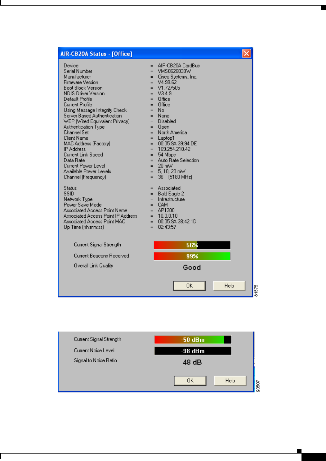
7-5
Cisco Aironet Wireless LAN Client Adapters Installation and Configuration Guide for Windows
OL-1394-06
Chapter 7 Performing Diagnostics Viewing the Current Status of Your Client Adapter
Figure 7-2 Status Screen (with Signal Strength as a Percentage)
Figure 7-3 Bottom of Status Screen (with Signal Strength in dBm)

7-6
Cisco Aironet Wireless LAN Client Adapters Installation and Configuration Guide for Windows OL-1394-06
Chapter 7 Performing Diagnostics
Viewing the Current Status of Your Client Adapter
Table 7-3 interprets each element of the Status screen.
Table 7-3 Client Adapter Status
Status Description
Device A description of your client adapter.
Serial Number The serial number of your client adapter.
Note The serial number appears only if the number has been
programmed into your card.
Manufacturer The manufacturer of your client adapter.
Firmware Version The version of the firmware that is currently running on your client
adapter.
Boot Block Version The version of the boot block firmware that is currently in your client
adapter. The boot block firmware contains identification information
for the client adapter and functions to start up the radio and pass control
to the main firmware, which (unlike the boot block) can be modified
and upgraded by the user.
NDIS Driver Version The version of the NDIS device driver that is currently installed on your
computer.
Default Profile The network configuration (or profile) shown in the Use Selected
Profile drop-down box on the Profile Manager screen. This is the
profile that you have selected as the active profile.
Note The current profile may be different than the default profile if
you are using auto profile selection. The client adapter will not
switch profiles as long as it remains associated to the access
point or reassociates within 10 seconds (or within the time
specified by the LEAP authentication timeout value if LEAP is
enabled). Refer to Chapter 4 for information on creating and
using profiles.
Current Profile The network configuration (or profile) your client adapter is currently
using.
Note The current profile may be different than the default profile if
you are using auto profile selection. The client adapter does not
switch profiles as long as it remains associated to the access
point or reassociates within 10 seconds (or within the time
specified by the LEAP authentication timeout value if LEAP is
enabled). Refer to Chapter 4 for information on creating and
using profiles.
Note If your current profile becomes disabled due to an invalid LEAP
username and password, this field lists the profile as Disabled.
Using Short Radio Headers Indicates whether your client adapter is actually using short radio
headers.
Value: Yes or No
Note This setting appears only for 2.4-GHz client adapters.
Note Refer to the Use Short Radio Headers parameter in Table 5-3
for information on using short radio headers.

7-7
Cisco Aironet Wireless LAN Client Adapters Installation and Configuration Guide for Windows
OL-1394-06
Chapter 7 Performing Diagnostics Viewing the Current Status of Your Client Adapter
Using Message Integrity
Check Indicates whether your client adapter is using message integrity check
(MIC) to protect packets sent to and received from the access point.
MIC prevents bit-flip attacks on encrypted packets. During a bit-flip
attack, an intruder intercepts an encrypted message, alters it slightly,
and retransmits it, and the receiver accepts the retransmitted message
as legitimate.
Note MIC is supported automatically by the client adapter’s driver,
but it must be enabled on the access point.
Value: Yes or No
Server Based Authentication Indicates the configuration of the access point to which your client
adapter is associated.
Value: None, WEP Key In Use, Cell Is Secure, or LEAP
Authenticated
Server Based Authentication Description
None The access point is configured for No
Encryption.
WEP Key In Use The access point is configured for
Optional encryption.
Cell Is Secure The access point is configured for Full
Encryption.
Note If the client’s current profile does
not have Allow Association to
Mixed Cells enabled, the client
can associate only to access points
that use full encryption.
LEAP Authenticated The client is using LEAP and is
authenticated to an access point that has
WEP and Network-EAP enabled.
WEP (Wired Equivalent
Privacy) Your client adapter’s current WEP status.
Value: Enabled, Not Enabled, or Need Firmware Upgrade
Note Refer to the “Setting Network Security Parameters” section on
page 5-20 for information on enabling WEP.
Authentication Type Indicates whether the client adapter must share the same WEP keys as
the access point in order to communicate or can communicate with the
access point regardless of its WEP settings.
Value: Open or Shared Key
Note Refer to the “Setting Network Security Parameters” section on
page 5-20 for information on setting the authentication type.
Table 7-3 Client Adapter Status (continued)
Status Description

7-8
Cisco Aironet Wireless LAN Client Adapters Installation and Configuration Guide for Windows OL-1394-06
Chapter 7 Performing Diagnostics
Viewing the Current Status of Your Client Adapter
Antenna Selection The antenna mode that your client adapter is currently using.
Value: Diversity, Primary Only, Secondary Only
(Primary Only is the only option available for PCI client
adapters)
Note This setting appears only for 2.4-GHz client adapters.
Note The Primary Only and Secondary Only values were formerly
named Right Only and Left Only, respectively. Refer to the
Antenna Mode (Receive) and Antenna Mode (Transmit)
parameters in Table 5-4 and Table 5-5 for information on
setting the antenna mode.
Channel Set The regulatory domain for which your client adapter is currently
configured, such as Americas. (For the Japan channel set, the Call ID is
also displayed.) This value is not user selectable.
Note Refer to Appendix D for a list of channel identifiers, channel
center frequencies, and regulatory domains for each channel.
Client Name The name your client adapter uses when it associates to an access point.
Note Refer to the Client Name parameter in Table 5-2 for
information on setting the client name.
MAC Address The MAC address assigned to your client adapter at the factory.
IP Address The IP address of your client adapter.
Current Link Speed The rate at which your client adapter is currently transmitting data
packets.
Value: 1, 2, 5.5, or 11 Mbps (2.4-GHz client adapters);
6, 9, 12, 18, 24, 36, 48, or 54 Mbps (5-GHz client adapters)
Data Rate The rate at which your client adapter has been configured to transmit or
receive data packets.
Value: 1 Mbps, 2 Mbps, 5.5 Mbps, 11 Mbps, or Auto Rate Selection
(2.4-GHz client adapters);
6 Mbps, 9 Mbps, 12 Mbps, 18 Mbps, 24 Mbps, 36 Mbps,
48 Mbps, 54 Mbps, or Auto Rate Selection (5-GHz client
adapters)
Note Refer to the Data Rate parameter in Table 5-3 for information
on setting the client adapter’s data rate.
Current Power Level The power level at which your client adapter is currently transmitting.
The maximum level is dependent upon the radio installed in your client
adapter and your country’s regulatory agency.
Value: 1, 5, 15, or 30 mW (340 series client adapters);
1, 5, 20, 30, 50, or 100 mW (350 series client adapters);
5, 10, or 20 mW (5-GHz client adapters)
Note Refer to the Transmit Power parameter in Table 5-3 for
information on setting the client adapter’s power level.
Table 7-3 Client Adapter Status (continued)
Status Description

7-9
Cisco Aironet Wireless LAN Client Adapters Installation and Configuration Guide for Windows
OL-1394-06
Chapter 7 Performing Diagnostics Viewing the Current Status of Your Client Adapter
Available Power Levels The power levels at which your client adapter is capable of
transmitting. The maximum level is dependent upon the radio installed
in your client adapter and your country’s regulatory agency.
Value: 1, 5, 15, or 30 mW (340 series client adapters);
1, 5, 20, 30, 50, or 100 mW (350 series client adapters);
5, 10, or 20 mW (5-GHz client adapters)
Note Refer to the Transmit Power parameter in Table 5-3 for
information on the client adapter’s available power levels.
Channel (Frequency) The frequency that your client adapter is currently using as the channel
for communications.
Value: Dependent on client adapter radio and regulatory domain
Note Refer to the Channel parameter in Table 5-3 for information on
selecting the frequency for your client adapter.
Status The operational mode of your client adapter.
Value: Error, Not Associated, Associated, Authenticating,
Authenticated, Authentication Failed, or Ad Hoc Mode
SSID The name of the network to which your client adapter is currently
associated.
Note Refer to the SSID1 parameter in Table 5-2 for information on
the client adapter’s SSID.
Network Type The type of network in which your client adapter is being used.
Value: Infrastructure or Ad Hoc
Note Refer to the Network Type parameter in Table 5-2 for
information on setting the network type.
Power Save Mode The client adapter’s current power consumption setting.
Value: CAM, Max PSP, or Fast PSP
Note Refer to the Power Save Mode parameter in Table 5-2 for
information on setting the client adapter’s power save mode.
Associated Access Point
Name The name of the access point to which your client adapter is associated.
It is shown only if the client adapter is in infrastructure mode, the
access point was configured with a name, and Aironet Extensions are
enabled (on access points running Cisco IOS release 12.2(4)JA or
greater).
Associated Access Point IP
Address The IP address of the access point to which your client adapter is
associated. It is shown only if the client adapter is in infrastructure
mode, the access point was configured with an IP address, and Aironet
Extensions are enabled (on access points running Cisco IOS release
12.2(4)JA or greater).
Note If Aironet Extensions are disabled, the IP address of the
associated access point is shown as 0.0.0.0.
Table 7-3 Client Adapter Status (continued)
Status Description

7-10
Cisco Aironet Wireless LAN Client Adapters Installation and Configuration Guide for Windows OL-1394-06
Chapter 7 Performing Diagnostics
Viewing the Current Status of Your Client Adapter
Associated Access Point
MAC Address The MAC address of the access point to which your client adapter is
associated. It is shown only if the client adapter is in infrastructure
mode.
Note This field displays the MAC address of the access point’s
Ethernet port (for access points that do not run Cisco IOS) or
the MAC address of the access point’s radio (for access points
that run Cisco IOS). The MAC address of the Ethernet port on
access points that run Cisco IOS is printed on a label on the
back of the device.
Beacon Period Specifies the duration between beacon packets, which are used to help
clients find each other in ad hoc mode.
Range: Approximately 20 to 999 milliseconds (ms)
Note The beacon period is shown only if your client adapter is in ad
hoc mode.
Up Time (hh:mm:ss) The amount of time (in hours:minutes:seconds) that the client adapter
has been receiving power. If the adapter has been running for more than
24 hours, the time is displayed in days, hours:minutes:seconds.
Current Signal Strength The signal strength for all received packets. The higher the value and
the more green the bar graph is, the stronger the signal.
Range: 0 to 100% or –95 to –45 dBm
Current Signal Quality
(2.4-GHz client adapters) The signal quality for all received packets. The higher the value and the
more green the bar graph is, the clearer the signal.
Range: 0 to 100%
Note This setting appears only for 2.4-GHz client adapters and only
if you selected signal strength to be displayed as a percentage.
See the Signal Strength Display Units parameter in Table 7-2
for information.
Current Noise Level
(2.4-GHz client adapters) The level of background radio frequency energy in the 2.4-GHz band.
The lower the value and the more green the bar graph is, the less
background noise present.
Range: –100 to –45 dBm
Note This setting appears only for 2.4-GHz client adapters and only
if you selected signal strength to be displayed in dBm. See the
Signal Strength Display Units parameter in Table 7-2 for
information.
Table 7-3 Client Adapter Status (continued)
Status Description

7-11
Cisco Aironet Wireless LAN Client Adapters Installation and Configuration Guide for Windows
OL-1394-06
Chapter 7 Performing Diagnostics Viewing Statistics for Your Client Adapter
Viewing Statistics for Your Client Adapter
ACU enables you to view statistics that indicate how data is being received and transmitted by your client
adapter.
To view your client adapter’s statistics, open ACU; then click the Statistics icon or select Statistics from
the Commands drop-down menu. The Statistics screen appears (see Figure 7-4).
Note The name of the current profile appears in parentheses at the top of the screen.
Note The receive and transmit statistics are host statistics. That is, they show packets and errors received or
sent by the Windows device. Link status tests from the access point or site survey tool are performed at
the firmware level; therefore, they have no effect on the statistics shown in the Statistics screen.
Current Beacons Received
(5-GHz client adapters) The percentage of beacon packets received versus those expected to be
received. The higher the value and the more green the bar graph is, the
clearer the signal.
Example: The access point sends out 10 beacons per second, so you
would expect the client adapter to receive 50 beacon packets
in 5 seconds. If it receives only 40 packets, the percentage of
beacons received would be 80%.
Range: 0 to 100%
Note This setting appears only for 5-GHz client adapters.
Overall Link Quality The client adapter’s ability to communicate with the access point,
which is determined by the combined result of the adapter’s signal
strength and signal quality.
Value: Not Associated, Poor, Fair, Good, or Excellent
Note This setting appears for 2.4-GHz client adapters (but only if you
selected signal strength to be displayed as a percentage) and for
5-GHz client adapters. See the Signal Strength Display Units
parameter in Table 7-2 for information.
Signal to Noise Ratio
(2.4-GHz client adapters) The difference between the signal strength and the current noise level.
The higher the value, the better the client adapter’s ability to
communicate with the access point.
Range: 0 to 90 dB
Note This setting appears only for 2.4-GHz client adapters and only
if you selected signal strength to be displayed in dBm. See the
Signal Strength Display Units parameter in Table 7-2 for
information.
Table 7-3 Client Adapter Status (continued)
Status Description
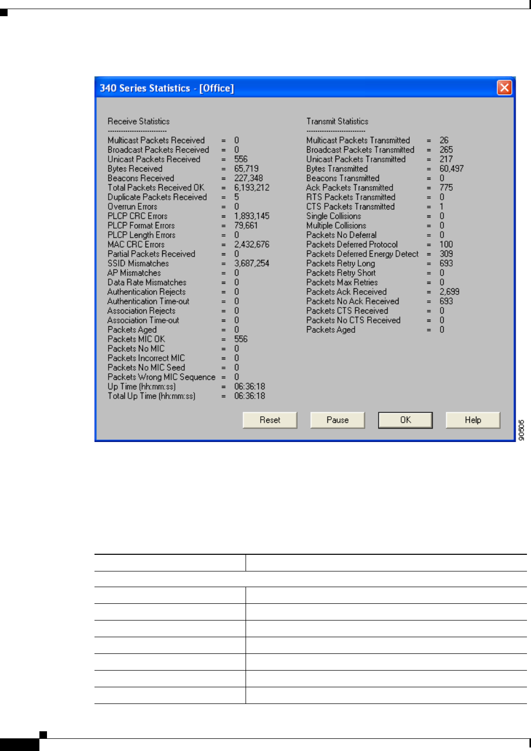
7-12
Cisco Aironet Wireless LAN Client Adapters Installation and Configuration Guide for Windows OL-1394-06
Chapter 7 Performing Diagnostics
Viewing Statistics for Your Client Adapter
Figure 7-4 Statistics Screen
The statistics are calculated as soon as your client adapter is started or the Reset button is selected and
are continually updated at the rate specified by the Screen Update Timer. Instructions for changing the
Screen Update Timer setting are provided in Table 7-2.
Table 7-4 describes each statistic that is displayed for your client adapter.
Table 7-4 Client Adapter Statistics
Statistic Description
Receive Statistics
Multicast Packets Received The number of multicast packets that were received successfully.
Broadcast Packets Received The number of broadcast packets that were received successfully.
Unicast Packets Received The number of unicast packets that were received successfully.
Bytes Received The number of bytes of data that were received successfully.
Beacons Received The number of beacon packets that were received successfully.
Total Packets Received OK The number of all packets that were received successfully.
Duplicate Packets Received The number of duplicate packets that were received successfully.

7-13
Cisco Aironet Wireless LAN Client Adapters Installation and Configuration Guide for Windows
OL-1394-06
Chapter 7 Performing Diagnostics Viewing Statistics for Your Client Adapter
Overrun Errors The number of packets received when no receive buffers were
available. These errors usually occur when the host does not read
the received packets from the client adapter fast enough.
PLCP CRC Errors The number of times the client adapter started to receive an
802.11 physical layer convergence protocol (PLCP) header but
the rest of the packet was ignored due to a cyclic redundancy
check (CRC) error in the header.
Note CRC errors can be attributed to packet collisions caused
by a dense population of client adapters, overlapping
access point coverage on a channel, high multipath
conditions from bounced signals, or the presence of other
2.4-GHz signals from devices such as microwave ovens,
wireless handset phones, etc.
PLCP Format Errors The number of times an 802.11 PLCP header was received with a
valid CRC but the rest of the packet was ignored due to an
unknown value in the header.
PLCP Length Errors The number of times an 802.11 PLCP header was received but the
rest of the packet was ignored due to an illegal header length.
MAC CRC Errors The number of packets that had a valid 802.11 PLCP header but
contained a CRC error in the data portion of the packet.
Note CRC errors can be attributed to packet collisions caused
by a dense population of client adapters, overlapping
access point coverage on a channel, high multipath
conditions from bounced signals, or the presence of other
2.4-GHz signals from devices such as microwave ovens,
wireless handset phones, etc.
Partial Packets Received The number of fragments that were discarded because the entire
packet was not received successfully.
SSID Mismatches The number of times the client adapter tried to associate to an
access point but was unable to because the adapter’s SSID was not
the same as the access point’s.
AP Mismatches The number of times the client adapter tried to associate to an
access point but was unable to because the access point was not
the adapter’s specified access point.
Note Refer to the Specified Access Point 1- 4 parameter in
Table 5-4 for information on specifying access points.
Data Rate Mismatches The number of times the client adapter tried to associate to an
access point but was unable to because the adapter’s data rate was
not supported by the access point.
Note Refer to the Data Rate parameter in Table 5-3 for
information on supported data rates.
Authentication Rejects The number of times the client adapter tried to authenticate to an
access point but was rejected.
Table 7-4 Client Adapter Statistics (continued)
Statistic Description

7-14
Cisco Aironet Wireless LAN Client Adapters Installation and Configuration Guide for Windows OL-1394-06
Chapter 7 Performing Diagnostics
Viewing Statistics for Your Client Adapter
Authentication Time-out The number of times the client adapter tried to authenticate to an
access point but was unable to because the access point did not
respond fast enough (timed out).
Association Rejects The number of times the client adapter tried to associate to an
access point but was rejected.
Association Time-out The number of times the client adapter tried to associate to an
access point but was unable to because the access point did not
respond fast enough (timed out).
Packets Aged The number of packets received successfully but discarded by the
client adapter because either all fragments were not received
within 10 seconds or the host did not read the packet from the
adapter within 10 seconds.
Packets MIC OK The number of packets that were received successfully with a
valid message integrity check (MIC).
Note This field is not displayed if MIC is not enabled on the
access point.
Packets No MIC The number of packets that were discarded due to no MIC being
found.
Note This field is not displayed if MIC is not enabled on the
access point.
Packets Incorrect MIC The number of packets that were discarded due to an incorrect
MIC value.
Note This field is not displayed if MIC is not enabled on the
access point.
Packets No MIC Seed The number of packets that were discarded due to no MIC seed
being received.
Note This field is not displayed if MIC is not enabled on the
access point.
Packets Wrong MIC Sequence The number of packets that were discarded due to the MIC
sequence number being wrong.
Note This field is not displayed if MIC is not enabled on the
access point.
Up Time (hh:mm:ss) The amount of time (in hours:minutes:seconds) since the Reset
button was selected. If the client adapter has been running for
more than 24 hours, the time is displayed in days,
hours:minutes:seconds.
Total Up Time (hh:mm:ss) The amount of time (in hours:minutes:seconds) that the client
adapter has been receiving power. The total up time continues to
increment even if the Reset button is selected. If the adapter has
been running for more than 24 hours, the time is displayed in
days, hours:minutes:seconds.
Table 7-4 Client Adapter Statistics (continued)
Statistic Description

7-15
Cisco Aironet Wireless LAN Client Adapters Installation and Configuration Guide for Windows
OL-1394-06
Chapter 7 Performing Diagnostics Viewing Statistics for Your Client Adapter
Transmit Statistics
Multicast Packets Transmitted The number of multicast packets that were transmitted
successfully.
Broadcast Packets Transmitted The number of broadcast packets that were transmitted
successfully.
Unicast Packets Transmitted The number of unicast packets that were transmitted successfully.
Bytes Transmitted The number of bytes of data that were transmitted successfully.
Beacons Transmitted The number of beacon packets that were transmitted successfully
(in ad hoc mode only).
Ack Packets Transmitted The number of acknowledgment (Ack) packets that were
transmitted in response to successfully received unicast packets.
RTS Packets Transmitted The number of request-to-send (RTS) packets that were
transmitted successfully.
CTS Packets Transmitted The number of clear-to-send (CTS) packets that were transmitted
in response to a successfully received RTS packet.
Single Collisions The number of packets that had to be retransmitted once due to a
collision.
Multiple Collisions The number of packets that had to be retransmitted more than
once due to additional collisions.
Packets No Deferral The number of packets that were able to be transmitted
immediately without being delayed due to energy detect or
protocol deferral.
Packets Deferred Protocol The number of packets that were delayed due to 802.11 protocol
reasons (such as not enough time left to send the packet).
Packets Deferred Energy Detect The number of packets that were delayed because RF energy was
already detected. This condition is usually caused by another
radio transmitting a packet or by some other RF source jamming
the signal (such as a microwave oven).
Packets Retry Long The number of normal data packets that were retransmitted.
Packets Retry Short The number of request-to-send (RTS) packets that were
retransmitted.
Packets Max Retries The number of packets that failed to be transmitted successfully
after exhausting the maximum number of retries.
Packets Ack Received The number of transmitted packets that had their corresponding
acknowledgment (Ack) packet received successfully.
Packets No Ack Received The number of transmitted packets that did not have their
corresponding Ack packet received successfully.
Packets CTS Received The number of clear-to-send (CTS) packets that were received in
response to an RTS packet.
Table 7-4 Client Adapter Statistics (continued)
Statistic Description
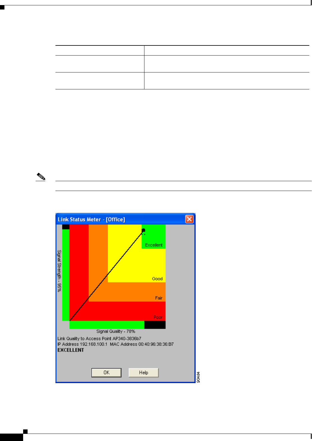
7-16
Cisco Aironet Wireless LAN Client Adapters Installation and Configuration Guide for Windows OL-1394-06
Chapter 7 Performing Diagnostics
Viewing the Link Status Meter
Viewing the Link Status Meter
ACU’s link status meter can be used to assess the performance of your client adapter’s RF link. If this
tool is used to assess the RF link at various locations, you can avoid areas where performance is weak
and eliminate the risk of losing the connection between your client adapter and an access point.
To open the link status meter, open ACU; then click the Link Status Meter icon or select Link Status
Meter from the Commands drop-down menu. The Link Status Meter screen appears (see Figure 7-5).
Note The name of the current profile appears in parentheses at the top of the screen.
Figure 7-5 Link Status Meter Screen
Packets No CTS Received The number of packets for which no CTS packet was received in
response to an RTS packet.
Packets Aged The number of packets that were discarded by the client adapter
because they were not transmitted successfully within 5 seconds.
Table 7-4 Client Adapter Statistics (continued)
Statistic Description

7-17
Cisco Aironet Wireless LAN Client Adapters Installation and Configuration Guide for Windows
OL-1394-06
Chapter 7 Performing Diagnostics Running an RF Link Test
The Link Status Meter screen provides a graphical display of the following:
•Signal strength—The strength of the client adapter’s radio signal at the time packets are being
received. It is displayed as a percentage along the vertical axis.
•Signal quality—The quality of the client adapter’s radio signal at the time packets are being
received. It is displayed as a percentage along the horizontal axis.
The combined result of the signal strength and signal quality is represented by a diagonal line (see
Figure 7-5). Where the line falls on the graphical display determines whether the RF link between your
client adapter and its associated access point is poor, fair, good, or excellent. The name, IP address, and
MAC address of the access point that is associated to your client adapter are indicated at the bottom of
the display.
Note The access point name and IP address are shown only if the client adapter is in infrastructure mode, the
access point was configured with a name and an IP address, and Aironet Extensions are enabled (on
access points running Cisco IOS release 12.2(4)JA or greater).
Note The access point MAC address is shown only if the client adapter is in infrastructure mode. This field
displays the MAC address of the access point’s Ethernet port (for access points that do not run Cisco
IOS) or the MAC address of the access point’s radio (for access points that run Cisco IOS). The MAC
address of the Ethernet port on access points that run Cisco IOS is printed on a label on the back of the
device.
Note ACU’s Status screen also shows signal strength and signal quality. However on the Status screen, these
data are represented by histograms.
If you want to see a recent history of the RF performance between your client adapter and its associated
access point, check the Show History check box on the Aironet Client Utility Preferences screen. Black
dots on the graphical display show the performance of the last 50 signals.
Running an RF Link Test
ACU’s link test tool sends out pings to assess the performance of the RF link. The test is designed to be
performed multiple times at various locations throughout your area and is run at the data rate set on
ACU’s RF Network Properties screen (see the Data Rate parameter in Table 5-3). The results of the link
test can be used to determine RF network coverage and ultimately the required number and placement
of access points in your network. The test also helps you to avoid areas where performance is weak,
thereby eliminating the risk of losing the connection between your client adapter and its associated
access point.
Because the link test operates above the RF level, it does more than test the RF link between two network
devices. It also checks the status of wired sections of the network and verifies that TCP/IP and the proper
drivers have been loaded.
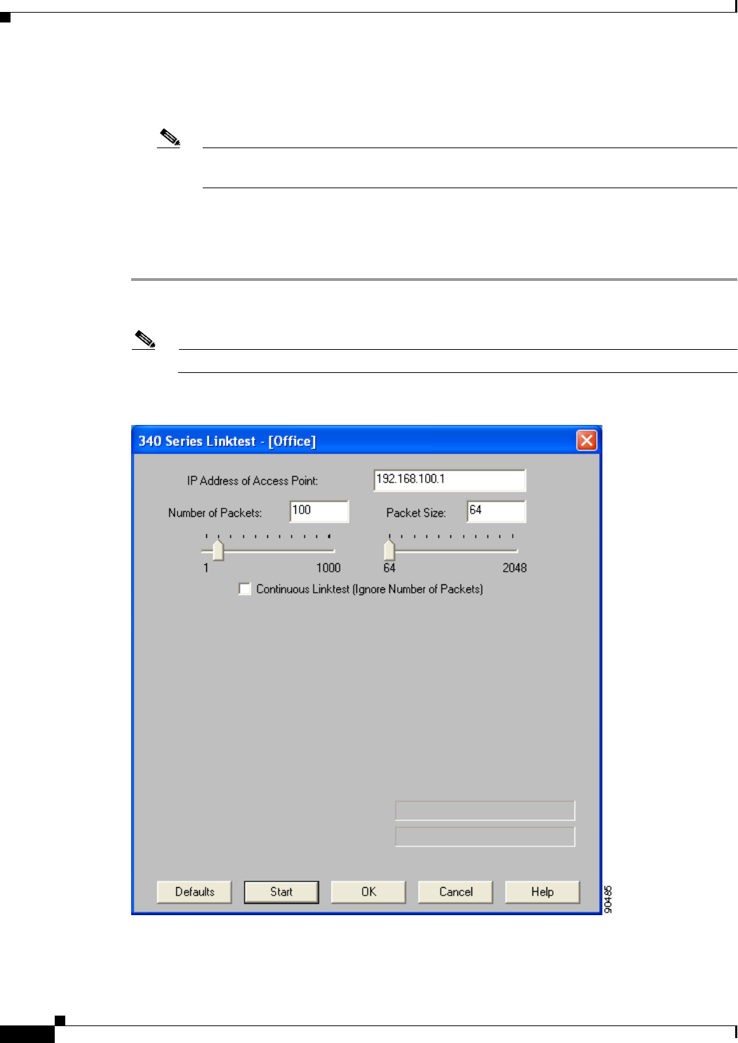
7-18
Cisco Aironet Wireless LAN Client Adapters Installation and Configuration Guide for Windows OL-1394-06
Chapter 7 Performing Diagnostics
Running an RF Link Test
The following prerequisites are required before you can run an RF link test:
•The TCP/IP protocol must be installed on your system.
Note See the Help section of your Windows operating system for information on installing and
setting up TCP/IP.
•An IP address must be configured for the access point (or other computer in ad hoc mode).
Follow the steps below to run an RF link test.
Step 1 Open ACU; then click the Link Test icon or select Linktest from the Commands drop-down menu. The
Linktest screen appears (see Figure 7-6).
Note The name of the current profile appears in parentheses at the top of the screen.
Figure 7-6 Linktest Screen

7-19
Cisco Aironet Wireless LAN Client Adapters Installation and Configuration Guide for Windows
OL-1394-06
Chapter 7 Performing Diagnostics Running an RF Link Test
Step 2 In the IP Address of Access Point field, enter the IP address of the access point or other wireless device
with which you want to test the RF link.
Step 3 You can set the link test to run until it has attempted to send a specific number of packets or to run until
you stop it. Follow one of the steps below to determine how long the link test will run:
•Select the number of packets that the link test should attempt to send. You can type a number in the
Number of Packets field or use the slider to select this value. (The Number of Packets parameter is
ignored if the Continuous Linktest check box is checked.)
Range: 1 to 1000
Default: 4
•Check the Continuous Linktest check box to allow the link test to run continuously.
Default: Unchecked
Step 4 Select the size of the data packet that is to be sent to the access point. You can type a number in the Packet
Size field or use the slider to select this value.
Range: 64 to 2048
Default: 100
Note The Windows TCP/IP stack fragments (splits up) packets that are greater than 512 bytes.
Therefore, the number of transmitted packets does not match the number of received packets
(even if none are lost) if the packet size is greater than 512 bytes.
Step 5 Click the Start button to run the link test. While the test is running, statistics are displayed and updated
periodically.
Figure 7-7 shows the Linktest screen with the signal strength values displayed as percentages, and
Figure 7-8 shows the bottom of the same screen with the signal strength values displayed in dBm.
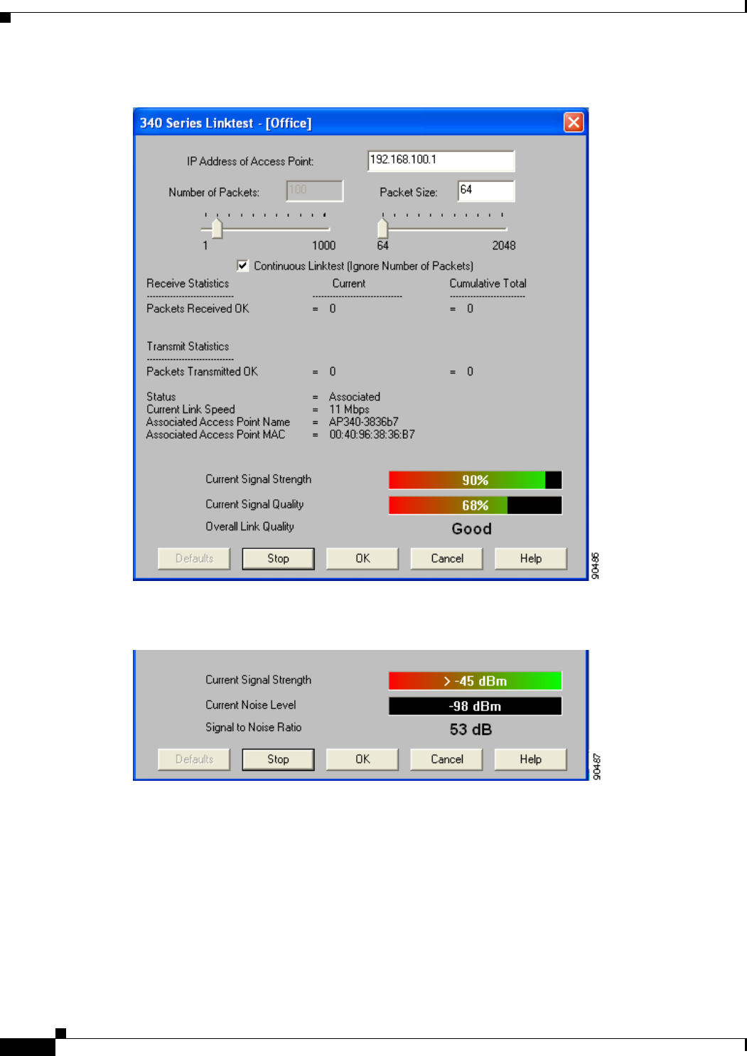
7-20
Cisco Aironet Wireless LAN Client Adapters Installation and Configuration Guide for Windows OL-1394-06
Chapter 7 Performing Diagnostics
Running an RF Link Test
Figure 7-7 Linktest Screen (with Test Running and Signal Strength as a Percentage)
Figure 7-8 Bottom of Linktest Screen (with Test Running and Signal Strength in dBm)

7-21
Cisco Aironet Wireless LAN Client Adapters Installation and Configuration Guide for Windows
OL-1394-06
Chapter 7 Performing Diagnostics Running an RF Link Test
Table 7-5 interprets the statistics that are displayed on the Linktest screen while the link test is running.
Table 7-5 Linktest Statistics
Linktest Statistic Description
Packets Received OK The number of packets of the specified size that have been
received successfully.
Packets Transmitted OK The number of packets of the specified size that have been
transmitted successfully.
Status The operational mode of your client adapter.
Value: Error, Configured, Associated, Not Associated, or
Ad Hoc Mode
Current Link Speed The rate at which your client adapter is currently transmitting
data packets.
Value: 1, 2, 5.5, or 11 Mbps (2.4-GHz client adapters);
6, 9, 12, 18, 24, 36, 48, or 54 Mbps (5-GHz client
adapters)
Associated Access Point Name The name of the access point to which your client adapter is
associated. It is shown only if the client adapter is in
infrastructure mode, the access point was configured with a name,
and Aironet Extensions are enabled (on access points running
Cisco IOS release 12.2(4)JA or greater).
Associated Access Point MAC
Address The MAC address of the access point to which your client adapter
is associated. It is shown only if the client adapter is in
infrastructure mode.
Note This field displays the MAC address of the access point’s
Ethernet port (for access points that do not run Cisco IOS)
or the MAC address of the access point’s radio (for access
points that run Cisco IOS). The MAC address of the
Ethernet port on access points that run Cisco IOS is
printed on a label on the back of the device.
Current Signal Strength The signal strength for all received packets. The higher the value
and the more green the bar graph is, the stronger the signal.
Range: 0 to 100% or –95 to –45 dBm
Current Signal Quality
(2.4-GHz client adapters) The signal quality for all received packets. The higher the value
and the more green the bar graph is, the clearer the signal.
Range: 0 to 100%
Note This setting appears only for 2.4-GHz client adapters and
only if you selected signal strength to be displayed as a
percentage. See the Signal Strength Display Units
parameter in Table 7-2 for information.

7-22
Cisco Aironet Wireless LAN Client Adapters Installation and Configuration Guide for Windows OL-1394-06
Chapter 7 Performing Diagnostics
Running an RF Link Test
Step 6 If you did not set the link test to run continuously, the test ends after the specified number of packets is
sent, and the Stop button changes back to the Start button. To stop the link test at any time, click Stop,
OK, or Cancel.
Current Noise Level
(2.4-GHz client adapters) The level of background radio frequency energy in the 2.4-GHz
band. The lower the value and the more green the bar graph is, the
less background noise present.
Range: –100 to –45 dBm
Note This setting appears only for 2.4-GHz client adapters and
only if you selected signal strength to be displayed in
dBm. See the Signal Strength Display Units parameter in
Table 7-2 for information.
Current Beacons Received
(5-GHz client adapters)
The percentage of beacon packets received versus those expected
to be received. The higher the value and the more green the bar
graph is, the clearer the signal.
Example: The access point sends out 10 beacons per second, so
you would expect the client adapter to receive 50
beacon packets in 5 seconds. If it receives only 40
packets, the percentage of beacons received would be
80%.
Range: 0 to 100%
Note This setting appears only for 5-GHz client adapters.
Overall Link Quality The client adapter’s ability to communicate with the access point,
which is determined by the combined result of the adapter’s
signal strength and signal quality.
Value: Not Associated, Poor, Fair, Good, or Excellent
Note This setting appears for 2.4-GHz client adapters (but only
if you selected signal strength to be displayed as a
percentage) and for 5-GHz client adapters. See the Signal
Strength Display Units parameter in Table 7-2 for
information.
Signal to Noise Ratio
(2.4-GHz client adapters) The difference between the signal strength and the current noise
level. The higher the value, the better the client adapter’s ability
to communicate with the access point.
Range: 0 to 90 dB
Note This setting appears only for 2.4-GHz client adapters and
only if you selected signal strength to be displayed in
dBm. See the “Signal Strength Display Units” parameter
in Table 7-2 for information.
Table 7-5 Linktest Statistics (continued)
Linktest Statistic Description

CHAPTER
8-1
Cisco Aironet Wireless LAN Client Adapters Installation and Configuration Guide for Windows
OL-1394-06
8
Using the Aironet Client Monitor (ACM)
This chapter explains how to use the Aironet Client Monitor (ACM) to access status information about
your client adapter and perform basic tasks.
The following topics are covered in this chapter:
•Overview of ACM, page 8-2
•The ACM Icon, page 8-2
•Tool Tip Window, page 8-3
•Pop-Up Menu, page 8-5

8-2
Cisco Aironet Wireless LAN Client Adapters Installation and Configuration Guide for Windows OL-1394-06
Chapter 8 Using the Aironet Client Monitor (ACM)
Overview of ACM
Overview of ACM
ACM is an optional application that provides a small subset of the features available through ACU.
Specifically, it enables you to access status information about your client adapter and perform basic
tasks. ACM is accessible from an icon in the Windows system tray, making it easily accessible and
convenient to use.
The ACM icon appears only if a client adapter is installed in your computer and you did not disable ACM
during installation. If more than one client adapter is installed, an ACM icon appears in the system tray
for each adapter.
ACM provides information and options in the following ways:
•In the appearance of the icon itself
•Through a tool tip window that appears when you hover the cursor over the icon
•Through a pop-up menu that appears when you right-click the icon
The ACM Icon
The appearance of the ACM icon indicates the connection status of your client adapter. ACM reads the
client adapter status and updates the icon every 2 seconds. Table 8-1 interprets the different appearances
of the ACM icon.
Note Windows 98, 98 SE, 2000, and XP may display their own wireless network connection status icon in the
system tray. Cisco recommends that you turn off the Windows icon and use the ACM icon to monitor
your wireless connection.
Table 8-1 Interpreting the ACM Icon
Icon Description
The client adapter’s radio is turned off.
The client adapter is not associated to an access point.
The client adapter is associated to an access point, but the user is not authenticated.
The client adapter is associated to an access point, and the link quality is excellent or
good.
The client adapter is associated to an access point, and the link quality is fair.
The client adapter is associated to an access point, and the link quality is poor.

8-3
Cisco Aironet Wireless LAN Client Adapters Installation and Configuration Guide for Windows
OL-1394-06
Chapter 8 Using the Aironet Client Monitor (ACM) Tool Tip Window
Tool Tip Window
When you hover the cursor over the ACM icon, the Tool Tip window appears (see Figure 8-1).
Figure 8-1 Tool Tip Window
This window provides information on the current status of your client adapter. Table 8-2 lists and
describes each element of the Tool Tip window.
Table 8-2 Tool Tip Window Elements
Status Element Description
Active profile The network configuration (or profile) that your client adapter is
currently using.
Note If auto profile selection is enabled, the profile name is preceded
by the word Auto.
Note If an application other than ACU was used to configure the
client adapter, Other Configuration Application appears.
SSID The name of the network to which your client adapter is currently
associated.
Note Refer to the SSID1 parameter in Table 5-2 for information on
setting the client adapter’s SSID.

8-4
Cisco Aironet Wireless LAN Client Adapters Installation and Configuration Guide for Windows OL-1394-06
Chapter 8 Using the Aironet Client Monitor (ACM)
Tool Tip Window
Connection status The operational mode of your client adapter.
Value: Radio Off, Not Associated, Associated, Authenticating,
Authenticated, or Authentication Failed
Connection Status Description
Radio Off The client adapter’s radio is turned off.
Not Associated The client adapter has not established a
connection to an access point.
Associated The client adapter has established a
connection to an access point.
Authenticating The client adapter is associated to an
access point, and the authentication
process has begun but not yet succeeded.
Authenticated The client adapter is associated to an
access point, and the user is authenticated.
Authentication Failed The client adapter is associated to an
access point, but the attempt to
authenticate the user has failed.
Note This status may appear very
briefly or not all as the
authentication failure may result
in the client adapter becoming
disassociated, in which case the
status reads “Not Associated.”
Link quality The client adapter’s ability to communicate with the access point,
which is determined by the combined result of the adapter’s signal
strength and signal quality.
Value: Excellent, Good, Fair, or Poor
Link speed The rate at which your client adapter is currently transmitting data
packets.
Value: 1, 2, 5.5, or 11 Mbps (2.4-GHz client adapters);
6, 9, 12, 18, 24, 36, 48, or 54 Mbps (5-GHz client adapters)
Client adapter type A description of your client adapter.
Client adapter IP address The IP address of your client adapter.
Table 8-2 Tool Tip Window Elements (continued)
Status Element Description
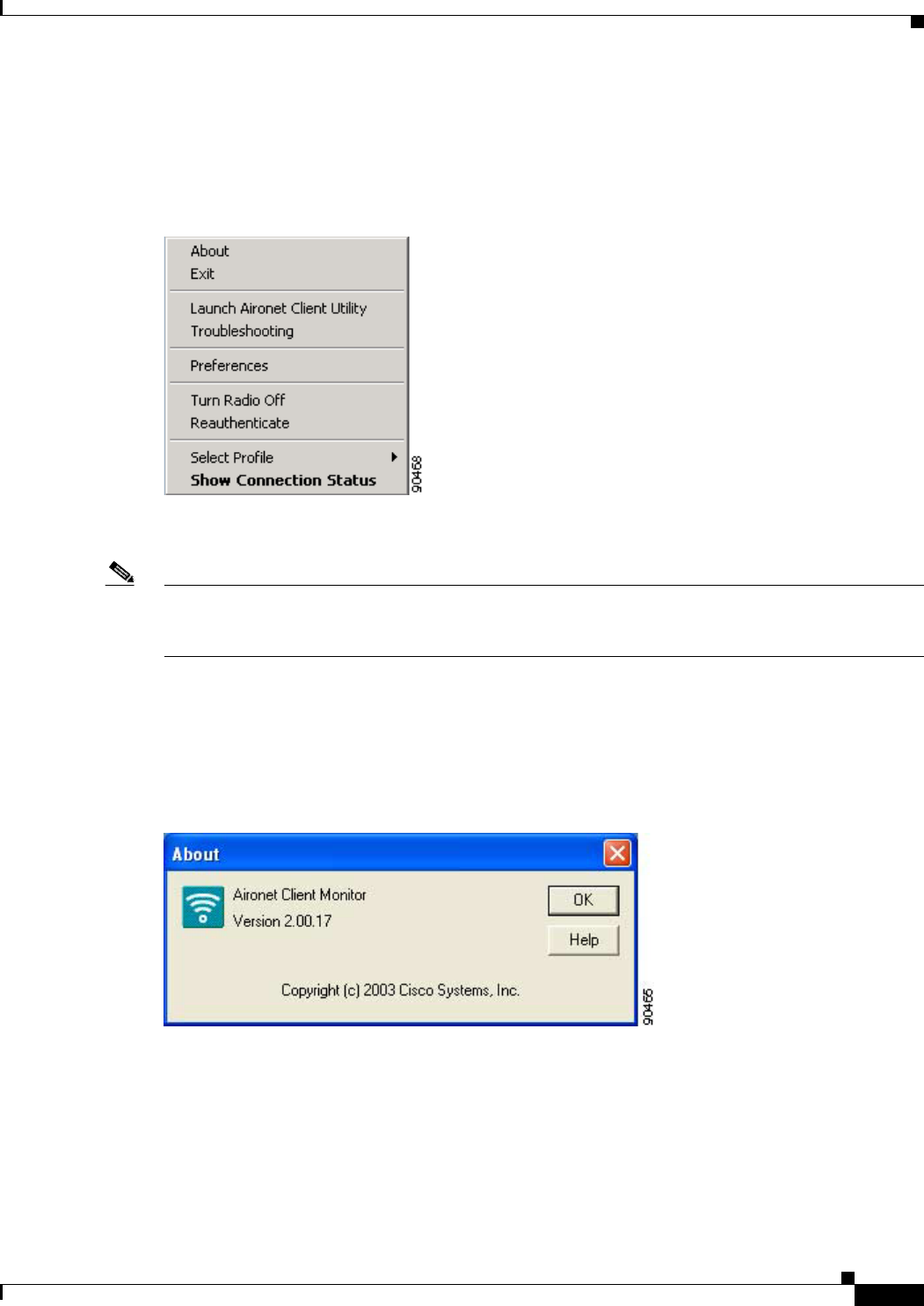
8-5
Cisco Aironet Wireless LAN Client Adapters Installation and Configuration Guide for Windows
OL-1394-06
Chapter 8 Using the Aironet Client Monitor (ACM) Pop-Up Menu
Pop-Up Menu
When you right-click the ACM icon, the ACM pop-up menu appears (see Figure 8-2).
Figure 8-2 ACM Pop-Up Menu
The following sections describe each ACM pop-up menu option.
Note If you used the Aironet Client Monitor Preferences screen or your system administrator used an
administrative tool to deactivate certain ACM menu options, these options do not appear in the menu and
therefore cannot be selected.
About
When you select this option, the About screen appears (see Figure 8-3).
Figure 8-3 ACM About Screen
The About screen displays the version number of ACM that your computer is running and enables you
to access the online help. To access the online help, click the Help button. An overview of ACM appears.
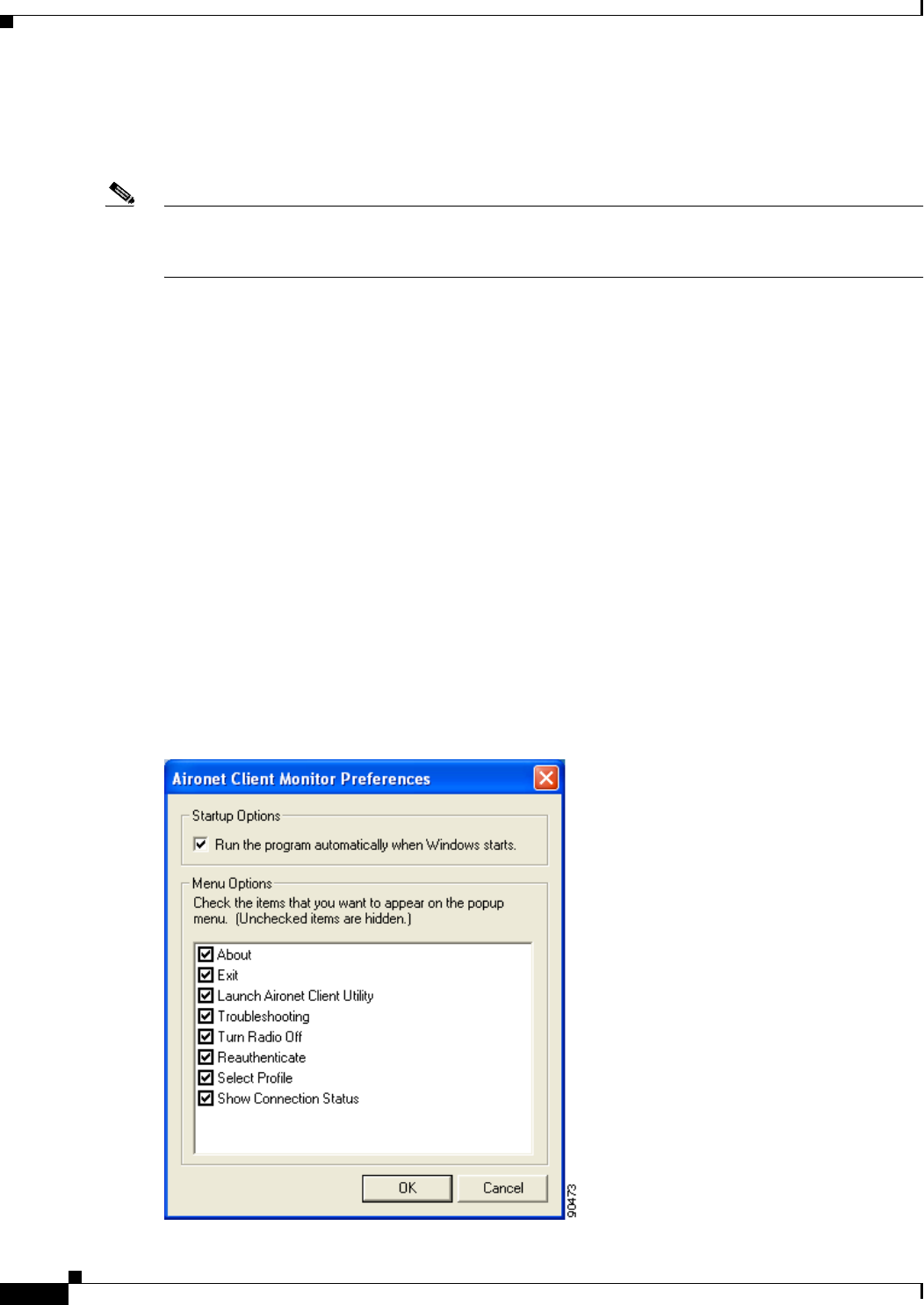
8-6
Cisco Aironet Wireless LAN Client Adapters Installation and Configuration Guide for Windows OL-1394-06
Chapter 8 Using the Aironet Client Monitor (ACM)
Pop-Up Menu
Exit
This option closes ACM for all client adapters.
Note To reactivate ACM, use Windows Explorer to find the path where the ACM software is installed. (The
default location is C:\Program Files\Cisco Systems\Aironet Client Monitor.) Then double-click
ACUMon.exe.
Launch Aironet Client Utility
This option activates ACU. It is available only if ACU is installed. If more than one ACM icon appears
in the Windows system tray, ACU initializes itself to use the client adapter associated with the icon that
initiated the launch.
Troubleshooting
This option activates the Cisco Wireless LAN Adapter Troubleshooting Utility, which enables you to
identify and resolve configuration and association problems with your client adapter. Refer to the “Using
the Troubleshooting Utility” section on page 10-4 for detailed instructions on using this utility.
Preferences
When you select this option, the Aironet Client Monitor Preferences screen appears (see Figure 8-4).
Figure 8-4 Aironet Client Monitor Preferences Screen

8-7
Cisco Aironet Wireless LAN Client Adapters Installation and Configuration Guide for Windows
OL-1394-06
Chapter 8 Using the Aironet Client Monitor (ACM) Pop-Up Menu
This screen enables you to determine when ACM runs and to select the options that appear on the ACM
pop-up menu. The selections you make apply to every instance of ACM. For example, if you deselect
the Troubleshooting option, it will not appear in the pop-up menu for any ACM icon.
Follow the steps below to make your selections.
Step 1 If you want ACM to run automatically when Windows starts, make sure the Run the program
automatically when Windows starts check box is checked. Otherwise, uncheck this check box.
Note If you do not select this option and later want to run ACM, you must use Windows Explorer to
find the path where the ACM software is installed. (The default location is C:\Program
Files\Cisco Systems\Aironet Client Monitor.) Then double-click ACUMon.exe.
Step 2 In the Menu Options portion of the screen, make sure the check boxes of all the options that you want
to appear in the ACM pop-up menu are checked. Any options that are not checked will not be included
in the menu.
Note The Preferences option cannot be deselected. It always appears in the ACM pop-up menu.
Step 3 Click OK to save your changes.
Turn Radio On/Off
This option enables you to turn the client adapter’s radio on or off. Turning the radio off prevents the
adapter from transmitting RF energy. You might want to turn off the client adapter’s radio in the
following situations:
•You are not transmitting data and want to conserve battery power.
•You have EAP-SIM authentication set up to occur transparently (the SIM card is left in the reader
and the PIN is stored in the computer), and you do not want to be billed for air time upon entering
an area that enables the client to authenticate.
•You are using a laptop on an airplane and want to prevent the adapter’s transmissions from
potentially interfering with the operation of certain devices.
When the radio is on, it periodically sends out probes even if it is not associated to an access point, as
required by the 802.11 specification. Therefore, it is important to turn it off around devices that are
susceptible to RF interference.
Note Your client adapter is not associated while the radio is off.
Note If your client adapter’s radio is turned off before your computer enters standby or hibernate mode or
before you reboot the computer, the radio remains off when the computer resumes. You must turn the
radio back on to resume operation.
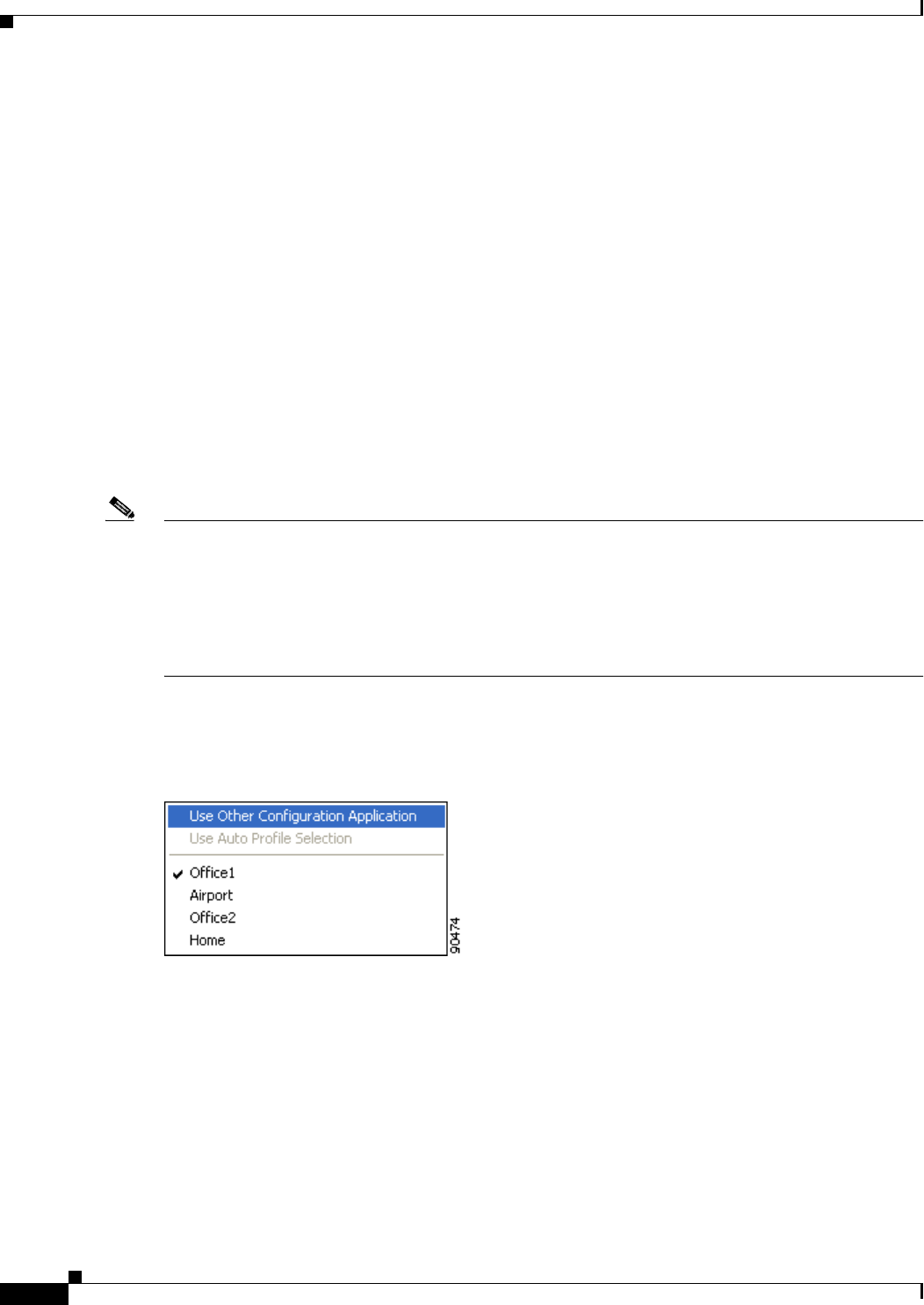
8-8
Cisco Aironet Wireless LAN Client Adapters Installation and Configuration Guide for Windows OL-1394-06
Chapter 8 Using the Aironet Client Monitor (ACM)
Pop-Up Menu
If the radio is on, select Turn Radio Off to turn off the radio.
If the radio is off, select Turn Radio On to turn on the radio.
Reauthenticate
This option enables you to force your client adapter to try to reauthenticate using the username and
password of the current profile.
If your client adapter was unable to authenticate using the specified username and password and you
have exhausted the retry limit (for example, LEAP tries only once to prevent you from being locked out
of the system), the current profile is disabled until you change the username or password, reboot your
computer, eject and reinsert the client adapter, or select the Reauthenticate option.
Select Profile
This option enables you to select the active profile for your client adapter.
Note Because EAP-TLS, PEAP, and EAP-SIM authentication are enabled in the operating system, you cannot
switch between these authentication types simply by switching profiles in ACM. You can select a profile
in ACM that uses host-based EAP, but you must enable the specific authentication type in Windows
(provided Windows is using the Microsoft 802.1X supplicant). In addition, Windows can be set for only
one authentication type at a time; therefore, if more than one profile in ACM uses host-based EAP and
you want to use another authentication type, you must change authentication types in Windows after
switching profiles in ACM.
When you select Select Profile from the ACM pop-up menu, a profiles submenu appears (see
Figure 8-5).
Figure 8-5 Profiles Submenu
From this menu, you can choose among the following options:
•Use Other Configuration Application—Enables an application other than ACU to configure the
client adapter. Examples of such applications include Windows XP and Boingo.
•Use Auto Profile Selection—Causes the client adapter’s driver to automatically select a profile
from the list of profiles that were set up in ACU to be included in auto profile selection.
If the client adapter loses association for more than 10 seconds (or for more than the time specified
by the LEAP authentication timeout value on the LEAP Settings screen if LEAP is enabled), the
driver switches automatically to another profile that is included in auto profile selection. The adapter
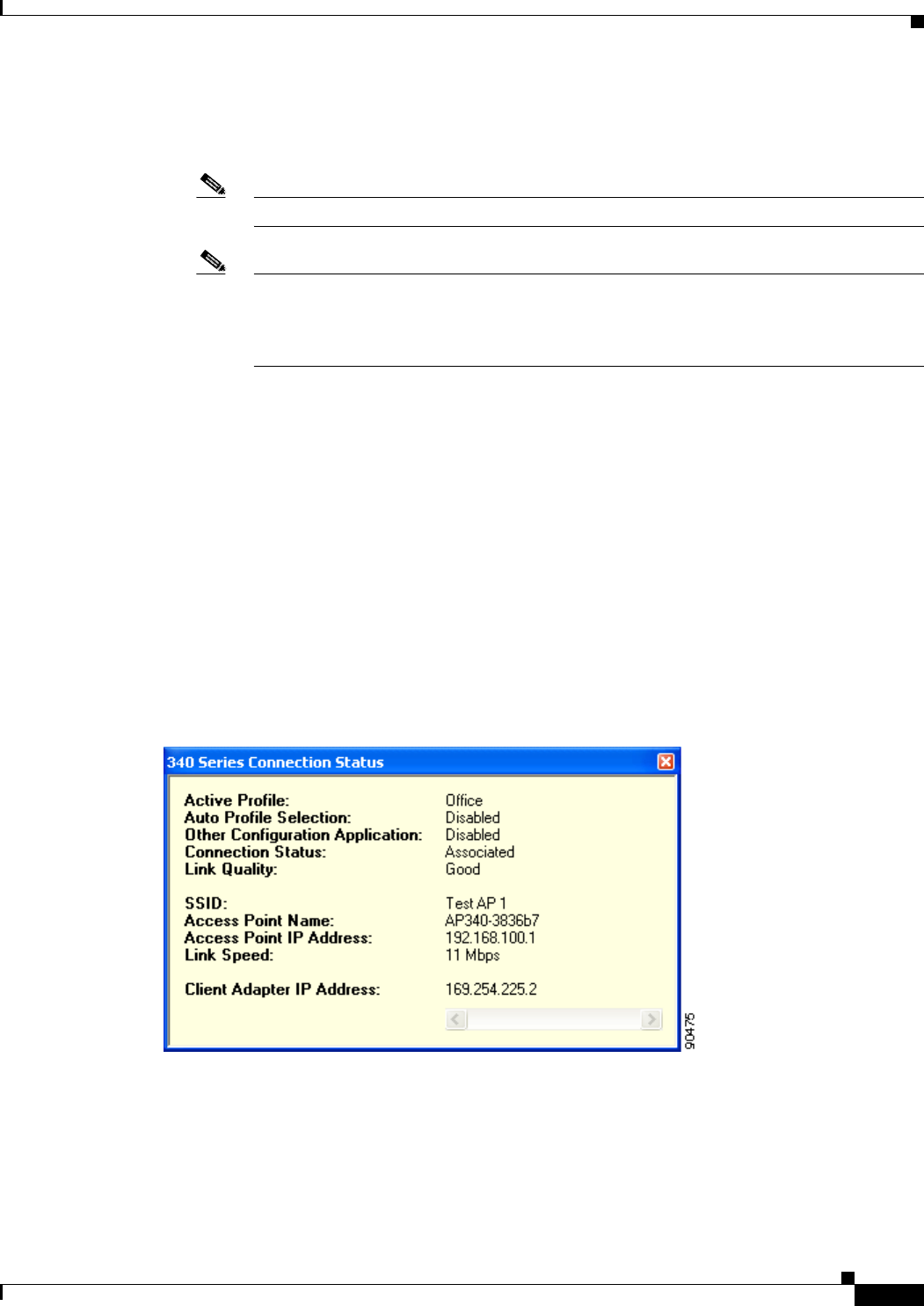
8-9
Cisco Aironet Wireless LAN Client Adapters Installation and Configuration Guide for Windows
OL-1394-06
Chapter 8 Using the Aironet Client Monitor (ACM) Pop-Up Menu
will not switch profiles as long as it remains associated or reassociates within 10 seconds (or within
the time specified by the LEAP authentication timeout value). To force the client adapter to associate
to a different access point, you must select a new profile.
Note This option is available only if two or more profiles are included in auto profile selection.
Note Login scripts are not reliable if you use auto profile selection with LEAP. If you LEAP
authenticate and achieve full network connectivity before or at the same time as you log into
the computer, the login scripts will run. However, if you LEAP authenticate and achieve full
network connectivity after you log into the computer, the login scripts will not run.
•A specific profile—When you select a profile from the list of available profiles, the client adapter
attempts to establish a connection to an access point using the parameters that were configured for
that profile.
If the client adapter cannot associate to the access point or loses association while using the selected
profile, the adapter does not attempt to associate using another profile. To associate, you must select
a different profile or select Use Auto Profile Selection.
Simply click the desired profile to select it. A check mark appears beside the profile, and the client
adapter attempts to establish a connection using the selected profile.
Show Connection Status
When you select this option, the Connection Status screen appears (see Figure 8-6).
Figure 8-6 Connection Status Screen

8-10
Cisco Aironet Wireless LAN Client Adapters Installation and Configuration Guide for Windows OL-1394-06
Chapter 8 Using the Aironet Client Monitor (ACM)
Pop-Up Menu
This screen provides information on the current status of your client adapter. Table 8-3 interprets each
element of the Connection Status screen.
Note You can also access the Connection Status screen by double-clicking the ACM icon.
Table 8-3 Connection Status Screen Elements
Status Element Description
Active Profile The network configuration (or profile) that your client adapter is
currently using.
Auto Profile Selection Indicates whether your client adapter is using auto profile selection.
Value: Enabled or Disabled
Other Configuration
Application Indicates whether an application other than ACU is being used to
configure your client adapter.
Value: Enabled or Disabled
Connection Status The operational mode of your client adapter.
Value: Radio Off, Not Associated, Associated, Authenticating,
Authenticated, or Authentication Failed
Connection Status Description
Radio Off The client adapter’s radio is turned off.
Not Associated The client adapter has not established a
connection to an access point.
Associated The client adapter has established a
connection to an access point.
Authenticating The client adapter is associated to an
access point, and the authentication
process has begun but not yet succeeded.
Authenticated The client adapter is associated to an
access point, and the user is authenticated.
Authentication Failed The client adapter is associated to an
access point, but the attempt to
authenticate the user has failed.
Note This status may appear very
briefly or not all as the
authentication failure may result
in the client adapter becoming
disassociated, in which case the
status reads “Not Associated.”
Link Quality The client adapter’s ability to communicate with the access point,
which is determined by the combined result of the adapter’s signal
strength and signal quality.
Value: Excellent, Good, Fair, or Poor

8-11
Cisco Aironet Wireless LAN Client Adapters Installation and Configuration Guide for Windows
OL-1394-06
Chapter 8 Using the Aironet Client Monitor (ACM) Pop-Up Menu
SSID The name of the network to which your client adapter is currently
associated.
Note Refer to the SSID1 parameter in Table 5-2 for information on
setting the client adapter’s SSID.
Access Point Name The name of the access point to which your client adapter is associated.
It is shown only if the client adapter is in infrastructure mode, the
access point was configured with a name, and Aironet Extensions are
enabled (on access points running Cisco IOS release 12.2(4)JA or
greater).
Access Point IP Address The IP address of the access point to which your client adapter is
associated. It is shown only if the client adapter is in infrastructure
mode, the access point was configured with an IP address, and Aironet
Extensions are enabled (on access points running Cisco IOS release
12.2(4)JA or greater).
Note If Aironet Extensions are disabled, the IP address of the
associated access point is shown as 0.0.0.0.
Link Speed The rate at which your client adapter is currently transmitting data
packets.
Value: 1, 2, 5.5, or 11 Mbps (2.4-GHz client adapters);
6, 9, 12, 18, 24, 36, 48, or 54 Mbps (5-GHz client adapters)
Client Adapter IP Address The IP address of your client adapter.
Table 8-3 Connection Status Screen Elements (continued)
Status Element Description

8-12
Cisco Aironet Wireless LAN Client Adapters Installation and Configuration Guide for Windows OL-1394-06
Chapter 8 Using the Aironet Client Monitor (ACM)
Pop-Up Menu

CHAPTER
9-1
Cisco Aironet Wireless LAN Client Adapters Installation and Configuration Guide for Windows
OL-1394-06
9
Routine Procedures
This chapter provides procedures for common tasks related to the client adapter.
The following topics are covered in this chapter:
•Inserting and Removing a Client Adapter, page 9-2
•Client Adapter Software Procedures, page 9-5
•Restarting the Client Adapter, page 9-15
•Turning Your Client Adapter’s Radio On or Off, page 9-15
•Uninstalling the Microsoft Hot Fix, page 9-16

9-2
Cisco Aironet Wireless LAN Client Adapters Installation and Configuration Guide for Windows OL-1394-06
Chapter 9 Routine Procedures
Inserting and Removing a Client Adapter
Inserting and Removing a Client Adapter
This section provides instructions for inserting and removing PC cards, PC-Cardbus cards, and PCI
cards. Instructions are not provided for LM cards and mini PCI cards because they are pre-installed
inside computing devices and are not meant to be installed or removed by the user.
Caution These procedures and the physical connections they describe apply generally to conventional PC card
slots, Cardbus slots, and PCI expansion slots. In cases of custom or nonconventional equipment, be alert
to possible differences in PC card slot, Cardbus slot, and PCI expansion slot configurations.
Inserting a Client Adapter
Follow the instructions in one of the sections below to insert a PC card, PC-Cardbus card, or PCI card
into a computing device.
Inserting a PC Card or PC-Cardbus Card
Step 1 Before you begin, examine the card. One end has a dual-row, 68-pin connector. The card is keyed so it
can be inserted only one way into the PC card slot or Cardbus slot.
Note The PC card slot or Cardbus slot is on the left or right side of the computer, depending on the
model.
Step 2 Perform one of the following:
•Turn on your computer, let the operating system boot up completely, and follow the remaining steps
in this section to insert the card.
•Turn off your computer, follow the remaining steps in this section to insert the card, and reboot your
computer.
Caution Do not force the card into your computer’s PC card slot or Cardbus slot. Forcing it will damage both the
card and the slot. If the card does not insert easily, remove the card and reinsert it.
Step 3 Hold the card with the Cisco logo facing up and insert it into the PC card slot or Cardbus slot, applying
just enough pressure to make sure it is fully seated (see Figure 9-1).
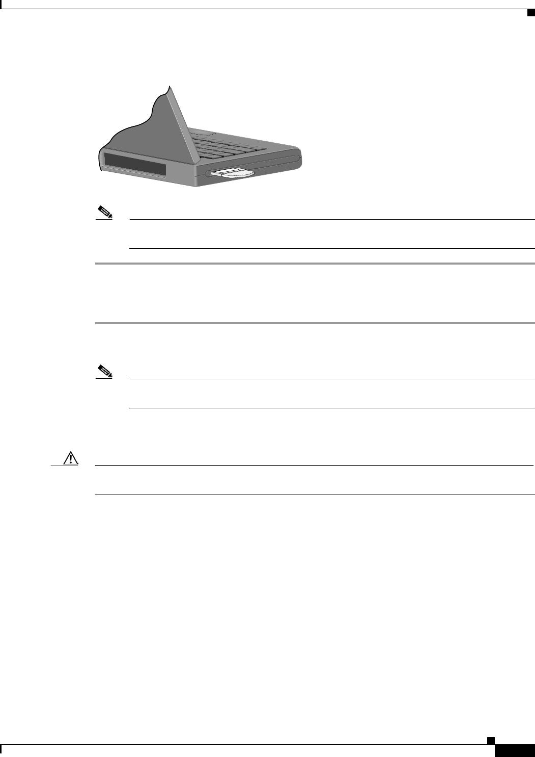
9-3
Cisco Aironet Wireless LAN Client Adapters Installation and Configuration Guide for Windows
OL-1394-06
Chapter 9 Routine Procedures Inserting and Removing a Client Adapter
Figure 9-1 Inserting a PC Card or PC-Cardbus Card into a Computing Device
Note The profiles for PC-Cardbus cards are tied to the slot in which the card is inserted. Therefore,
you must always insert your PC-Cardbus card into the same slot or create profiles for both slots.
Inserting a PCI Card
Step 1 Turn off the PC and all its components.
Step 2 Remove the computer cover.
Note On most Pentium PCs, PCI expansion slots are white. Refer to your PC documentation for slot
identification.
Step 3 Remove the screw from the top of the CPU back panel above an empty PCI expansion slot. This screw
holds the metal bracket on the back panel.
Caution Static electricity can damage your PCI card. Before removing the adapter from the anti-static packaging,
discharge static by touching a metal part of a grounded PC.
Step 4 Examine the PCI card. The antenna connector and the LEDs face out of your computer and are visible
when you put the cover back on. The bottom edge of the card is the connector you will insert into an
empty expansion slot in your computer. See Figure 9-2.
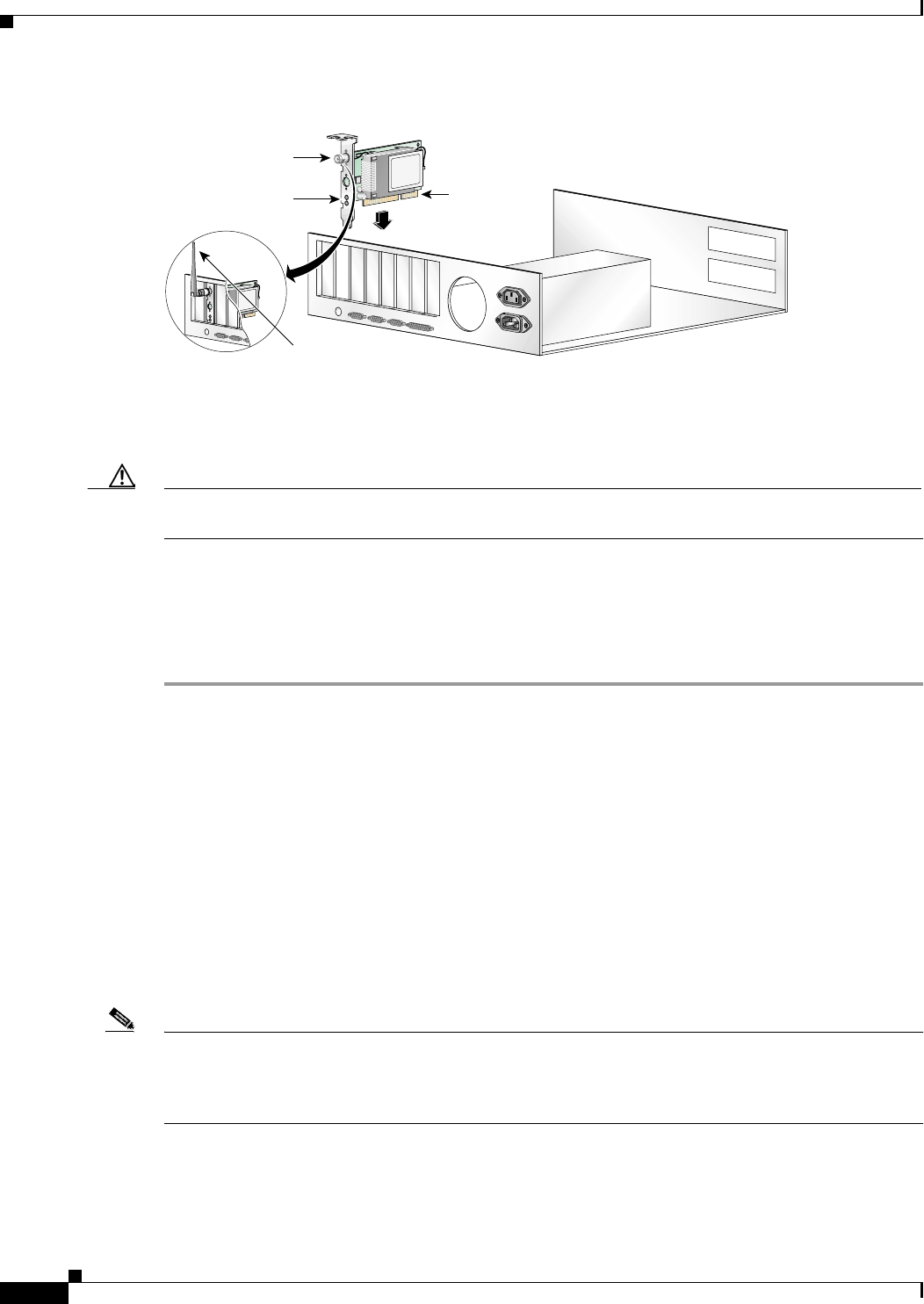
9-4
Cisco Aironet Wireless LAN Client Adapters Installation and Configuration Guide for Windows OL-1394-06
Chapter 9 Routine Procedures
Inserting and Removing a Client Adapter
Figure 9-2 Inserting a PCI Card into a PC
Step 5 Tilt the card to allow the antenna connector and LEDs to slip through the opening in the CPU back panel.
Step 6 Press the card into the empty slot until the connector is firmly seated.
Caution Do not force the card into the expansion slot as this could damage both the card and the slot. If the card
does not insert easily, remove it and reinsert it.
Step 7 Reinstall the screw on the CPU back panel and replace the computer cover.
Step 8 Attach the 2-dBi antenna to the card’s antenna connector until it is finger-tight. Do not overtighten.
Step 9 For optimal reception, position the antenna so it is straight up.
Step 10 Boot up your PC.
Removing a Client Adapter
Follow the instructions in one of the sections below to remove a PC card, PC-Cardbus card, or PCI card
from a computing device, when necessary.
Removing a PC Card or PC-Cardbus Card
To remove a PC card or PC-Cardbus card after it is successfully installed and configured (such as when
your laptop is to be transported), completely shut down your computer and pull the card directly out of
the PC card slot or Cardbus slot. When the card is reinserted and the computer is rebooted, your
connection to the network should be re-established.
Note If you need to remove your PC card or PC-Cardbus card but do not want to shut down your computer,
double-click the Unplug or Eject Hardware icon in the Windows system tray, select the Cisco Aironet
client adapter you want to remove under Hardware devices, click Stop, and click OK twice. Then pull
the card directly out of the card slot.
Antenna
connector
LEDs Card edge
connector
Standard 2 dBi
dipole antenna
47521

9-5
Cisco Aironet Wireless LAN Client Adapters Installation and Configuration Guide for Windows
OL-1394-06
Chapter 9 Routine Procedures Client Adapter Software Procedures
Removing a PCI Card
Because PCI client adapters are installed inside desktop computers, which are not designed for portable
use, you should have little reason to remove the adapter. However, instructions are provided below in
case you ever need to remove your PCI card.
Step 1 Completely shut down your computer.
Step 2 Disconnect the client adapter’s antenna.
Step 3 Remove the computer cover.
Step 4 Remove the screw from the top of the CPU back panel above the PCI expansion slot that holds your client
adapter.
Step 5 Pull up firmly on the client adapter to release it from the slot and carefully tilt the adapter to allow it to
clear the opening in the CPU back panel.
Step 6 Reinstall the screw on the CPU back panel and replace the computer cover.
Client Adapter Software Procedures
This section provides instructions for the following procedures:
•Finding the Install Wizard version, see below
•Upgrading the client adapter software, page 9-6
•Uninstalling the client adapter software, page 9-6
•Finding the driver version, page 9-7
•Firmware procedures, page 9-8
•ACU procedures, page 9-12
•ACM procedures, page 9-15
Finding the Install Wizard Version
Follow the instructions in this section to find the version of the Install Wizard that is currently installed
for your client adapter.
Step 1 Open Windows Explorer.
Step 2 Find the Install Wizard files.
Step 3 Right-click the Setup.exe file.
Step 4 Click Properties.
Step 5 Click the Version tab. The version of the currently installed Install Wizard file is shown in the File
version field.

9-6
Cisco Aironet Wireless LAN Client Adapters Installation and Configuration Guide for Windows OL-1394-06
Chapter 9 Routine Procedures
Client Adapter Software Procedures
Upgrading the Client Adapter Software
The same procedure that is used to initially install client adapter software can also be used to upgrade to
a more recent version. Refer to Chapter 3 for instructions on upgrading your client adapter’s software.
Note The client adapter’s firmware can also be upgraded through ACU. Refer to the “Upgrading the
Firmware” section on page 9-8 for details.
Uninstalling the Client Adapter Software
This section provides instructions for uninstalling any Cisco Aironet client adapter drivers, utilities, and
security modules that are installed on your computer. Only the client adapter’s firmware remains
installed. This procedure is necessary if you want to remove any installed client adapter software
components from your computer or downgrade to previous versions.
Note If you want to downgrade to earlier versions of client adapter software, follow the steps below to
uninstall the current software components. Then install the older software.
Note When you uninstall the client adapter software, any existing profiles are removed. If you want to save
your profiles for later use, follow the instructions in Chapter 4 to export your profiles before uninstalling
the software components.
Note This procedure does not uninstall the PC, LM, or PCI card driver that was bundled with Windows Me
and XP. It uninstalls only drivers to which you have upgraded. When you follow the steps below to
uninstall an upgraded driver and then eject and reinsert the card, Windows finds the original driver and
reinstalls it automatically.
Step 1 Perform one of the following:
•If you want to remove the client adapter from your computer, shut down your computer, remove the
client adapter, and reboot your computer.
•If you want to leave your client adapter inserted in your computer or if your client adapter is an LM
or mini PCI card and cannot be removed, go to Step 2.
Step 2 Select Start > Run.
Step 3 Browse to the location of the Install Wizard software, select the Setup.exe file, and click Open and OK.
The Cisco Aironet Wireless LAN Client Adapter Installation Wizard screen appears (see Figure 9-3).
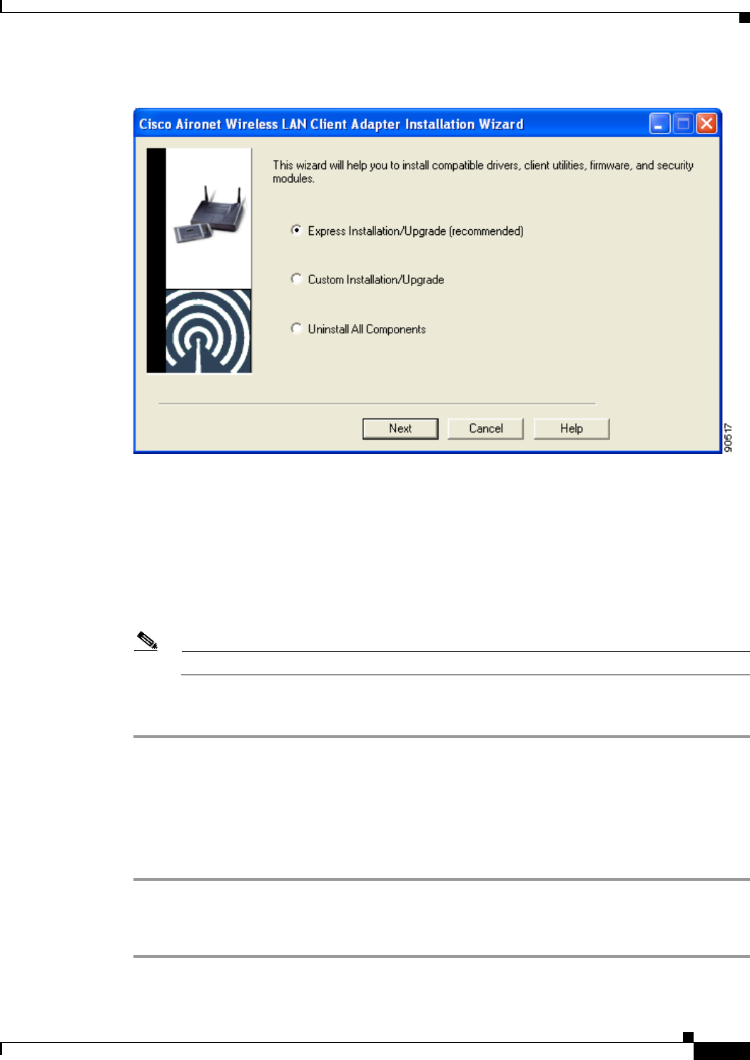
9-7
Cisco Aironet Wireless LAN Client Adapters Installation and Configuration Guide for Windows
OL-1394-06
Chapter 9 Routine Procedures Client Adapter Software Procedures
Figure 9-3 Cisco Aironet Wireless LAN Client Adapter Installation Wizard screen
Step 4 Select Uninstall All Components and click Next.
Step 5 When prompted to confirm your decision, click Yes. The process to uninstall the files begins. You are
notified throughout the process as each component is uninstalled.
Step 6 When the process completes, you are notified that the system is about to reboot. Close any open
applications and click OK.
Step 7 If you did not remove the client adapter from your computer, the Found New Hardware Wizard screen
appears after your computer reboots. Click Cancel.
Note The Found New Hardware Wizard screen does not appear on computers running Windows NT.
Step 8 This procedure does not remove the Install Wizard file or its uncompressed files. If you want to remove
them from your computer, find the files using Windows Explorer and delete them.
Finding the Driver Version
Follow the instructions in this section to find the version of the driver that is currently installed for your
client adapter.
Step 1 Open ACU.
Step 2 Click the Status icon or select Status from the Commands drop-down menu. The Status screen displays
the current version of your client adapter’s driver in the NDIS Driver Version field.

9-8
Cisco Aironet Wireless LAN Client Adapters Installation and Configuration Guide for Windows OL-1394-06
Chapter 9 Routine Procedures
Client Adapter Software Procedures
Firmware Procedures
This section provides instructions for the following procedures:
•Finding the Firmware Version, see below
•Upgrading the Firmware, see below
•Preventing the Driver from Upgrading the Firmware, page 9-10
Finding the Firmware Version
Follow the instructions in this section to find the version of firmware that is currently installed for your
client adapter.
Step 1 Open ACU.
Step 2 Click the Status icon or select Status from the Commands drop-down menu. The Status screen displays
the current version of your client adapter’s firmware in the Firmware Version field.
Upgrading the Firmware
Caution To minimize the risk of a power failure during the firmware flashing process, which could render your
client adapter inoperable, Cisco recommends that your computer be plugged into AC power or have a
fully charged battery at the start of flashing. If a power failure does occur, follow the instructions in the
“Technical Assistance Center” section of the Preface to contact TAC for assistance.
You can upgrade your client adapter’s firmware using either the Install Wizard or ACU. If you use the
wizard, the firmware loads from the Install Wizard file and is installed along with other software
components. If you use ACU, the firmware installs from an image (*.img) file that contains only
firmware.
Note To ensure compatibility between software components, Cisco recommends that you use the Install
Wizard to upgrade the firmware along with the other software components.
Using the Install Wizard
To upgrade the firmware using the Install Wizard, follow the instructions in the “Installing or Upgrading
the Client Adapter Software” section on page 3-2.

9-9
Cisco Aironet Wireless LAN Client Adapters Installation and Configuration Guide for Windows
OL-1394-06
Chapter 9 Routine Procedures Client Adapter Software Procedures
Using ACU
Note When you upgrade your client adapter’s firmware using ACU, the Automatically Load New Firmware
When NDIS Driver Is Updated parameter on the Aironet Client Utility Preferences screen becomes
disabled (or unchecked) automatically to prevent the newly loaded firmware from being overwritten by
the driver. If you ever want to enable this parameter, you must recheck the check box.
To upgrade the firmware using ACU, follow the steps below.
Step 1 Use the computer’s web browser to access the following URL:
http://www.cisco.com/public/sw-center/sw-wireless.shtml
Step 2 Select Option #2: Aironet Wireless Software Display Tables.
Note You can download software from the Software Selector tool instead of the display tables. To do
so, select Option #1: Aironet Wireless Software Selector, follow the instructions on the
screen, and go to Step 7.
Step 3 Select Cisco Aironet Wireless LAN Client Adapters.
Step 4 Under Individual Files, find the client adapter firmware.
Step 5 Click the link that corresponds to your client adapter’s model number (such as 340 or 350 series).
Step 6 Select the latest firmware file for your specific client adapter type (such as CB or MPI).
Note The firmware for PC, LM, and PCI cards is labeled PCMCIA-LMC-PCI, the firmware for mini
PCI cards is labeled mini PCI or MPI, and the firmware for PC-Cardbus cards is labeled CB.
Note If your wireless network uses EAP authentication, access points to which your client adapter will
attempt to authenticate must use the following firmware versions or greater: 11.23T (340 and
350 series access points), 12.2(4)JA (1100 series access points), or 11.54T (1200 series access
points).
Step 7 Read and accept the terms and conditions of the Software License Agreement.
Step 8 Select the firmware file again to download it.
Step 9 Save the file to a floppy disk or to your computer’s hard drive.
Step 10 Find the file using Windows Explorer, double-click it, and extract the image file to a folder.
Note To extract the file, click Browse on the WinZip Self-Extractor screen, select the folder in which
you want the file to be placed, and click OK and Unzip. After the file is extracted, click OK to
close the screen.
Step 11 Make sure the client adapter is installed in your computer and is operational.
Step 12 Open ACU; click the Load Firmware icon or select Load New Firmware from the Commands
drop-down menu. The Load New Firmware screen appears (see Figure 9-4).
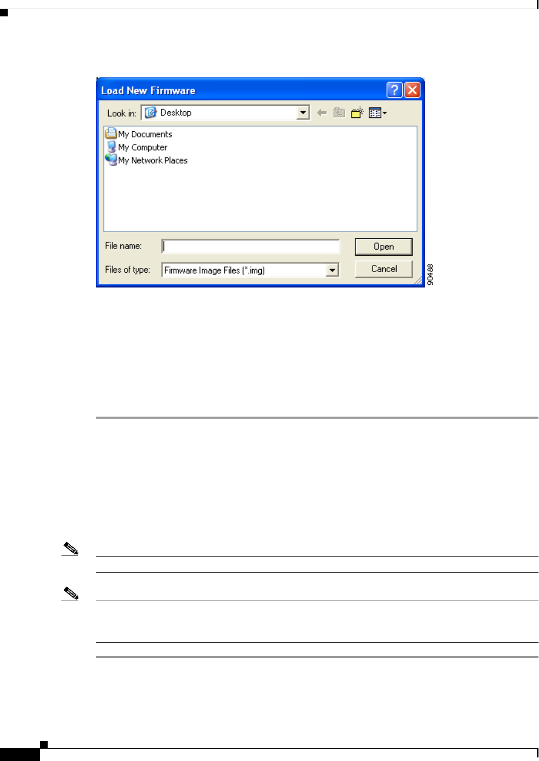
9-10
Cisco Aironet Wireless LAN Client Adapters Installation and Configuration Guide for Windows OL-1394-06
Chapter 9 Routine Procedures
Client Adapter Software Procedures
Figure 9-4 Load New Firmware Screen
Step 13 Find the location of the new firmware in the Look in box.
Step 14 Click the firmware image file (*.img) so that it appears in the File name box at the bottom of the screen.
Step 15 Click the Open button. A progress bar appears while the selected image is loaded into the client adapter’s
Flash memory.
Step 16 Click OK when the “Firmware Upgrade Complete!” message appears. The OK button cannot be selected
until the process is complete or an error occurs. If an error occurs, refer to the “Error Messages” section in
Chapter 10.
Preventing the Driver from Upgrading the Firmware
The Automatically Load New Firmware When NDIS Driver Is Updated parameter on the Aironet Client
Utility Preferences screen affects the firmware that is bundled with the driver, not the firmware that is
included in the Install Wizard. This parameter controls whether the driver (whenever it loads) installs
the firmware with which it is bundled. (The driver loads each time you insert a client adapter or reboot
your computer.)
Note To complete this procedure, you must have used the Install Wizard to install ACU.
Note The Automatically Load New Firmware When NDIS Driver Is Updated parameter is functionally
equivalent to the Disable Firmware Checking parameter in the Install Wizard. The parameter that is set
last is the one that governs how the driver behaves. Refer to Chapter 3 for additional information.
Step 1 Open ACU.
Step 2 Click the Preferences icon or select Preferences from the Options drop-down menu. The Aironet Client
Utility Preferences screen appears (see Figure 9-5).
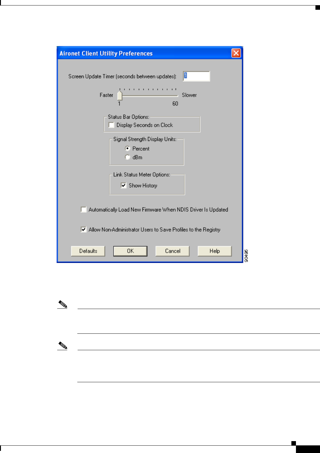
9-11
Cisco Aironet Wireless LAN Client Adapters Installation and Configuration Guide for Windows
OL-1394-06
Chapter 9 Routine Procedures Client Adapter Software Procedures
Figure 9-5 Aironet Client Utility Preferences Screen
Step 3 If you want to prevent the driver (when it loads) from installing the firmware with which it is bundled,
thereby allowing the client adapter to retain its current firmware version, make sure the Automatically
Load New Firmware When NDIS Driver Is Updated check box is not checked.
Note If you want the driver (when it loads) to install the firmware with which it is bundled if it is newer
than the firmware that is currently installed in the client adapter, make sure the Automatically
Load New Firmware When NDIS Driver Is Updated check box is checked.
Note When you upgrade your client adapter’s firmware using ACU, the Automatically Load New
Firmware When NDIS Driver Is Updated parameter becomes unchecked automatically to
prevent the newly loaded firmware from being overwritten by the driver. If you want to enable
this parameter, you must recheck the check box.

9-12
Cisco Aironet Wireless LAN Client Adapters Installation and Configuration Guide for Windows OL-1394-06
Chapter 9 Routine Procedures
Client Adapter Software Procedures
Note The Automatically Load New Firmware When NDIS Driver Is Updated parameter is dependent
on the radio type (and the Cardbus slot for PC-Cardbus cards). Therefore, if you insert a client
adapter of a different card type (such as a 340 instead of a 350) or insert the same PC-Cardbus
card into a different slot, whether or not the driver installs the firmware with which it is bundled
depends on how this parameter (or the Disable Firmware Checking parameter) was last set for
that card type or card slot.
Step 4 Click OK.
ACU Procedures
This section provides instructions for the following procedures:
•Opening ACU, below
•Exiting ACU, page 9-13
•Modifying ACU installation settings, page 9-13
•Finding the version of ACU, page 9-13
•Adding the ACU icon to or removing it from the desktop, page 9-14
•Accessing online help, page 9-14
Opening ACU
To open ACU, perform one of the following:
•Double-click the Aironet Client Utility (ACU) icon on your desktop.
•Select Aironet Client Utility (ACU) from the folder in the Windows Start Menu that you chose
during installation [the default location is Start > Program Files > Cisco Systems > Aironet Client
Utility (ACU)].
•Double-click My Computer > Control Panel > Aironet Client Utility.
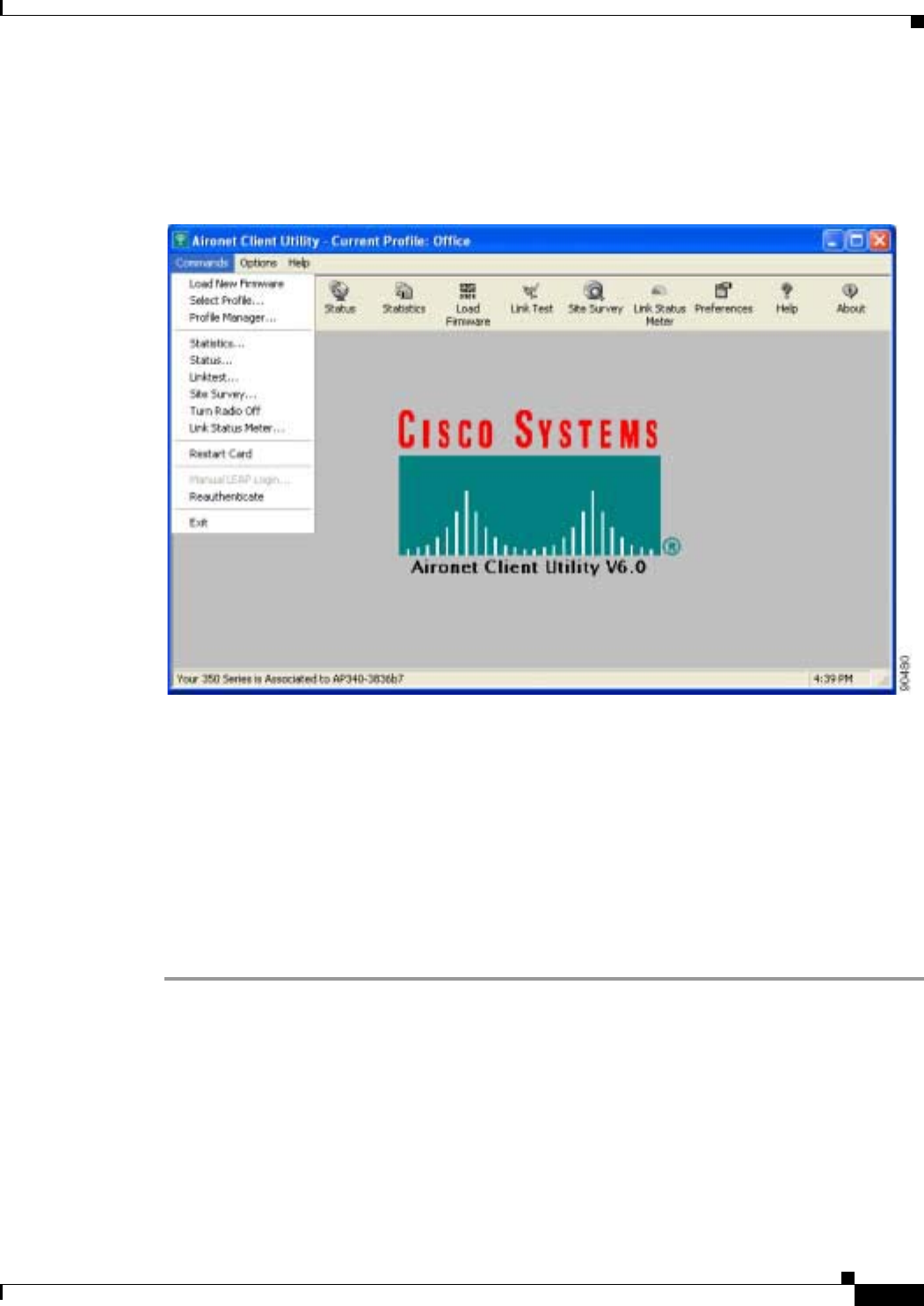
9-13
Cisco Aironet Wireless LAN Client Adapters Installation and Configuration Guide for Windows
OL-1394-06
Chapter 9 Routine Procedures Client Adapter Software Procedures
Exiting ACU
To exit ACU, select Exit from the Commands drop-down menu (see Figure 9-6).
Figure 9-6 Commands Drop-Down Menu
Modifying ACU Installation Settings
If you need to change any of the settings that you selected during installation (for example, placing the
ACU icon on the desktop or allowing a saved LEAP username and password), you must run the Install
Wizard again and modify the parameter values. Refer to Chapter 3 for instructions.
Finding the Version of ACU
Follow the instructions in this section to find the version of ACU that is currently installed.
Step 1 Open ACU.
Step 2 Click the About icon or select the About Aironet Client Utility option from the Help drop-down menu.
The About Aironet Client Utility screen appears (see Figure 9-7).
9-14
Cisco Aironet Wireless LAN Client Adapters Installation and Configuration Guide for Windows OL-1394-06
Chapter 9 Routine Procedures
Client Adapter Software Procedures
Figure 9-7 About Aironet Client Utility Screen
Adding the ACU Icon to or Removing it from the Desktop
By default, an ACU icon is added to your computer’s desktop when you install the Install Wizard.
•If you wish to remove the ACU icon from the desktop, run the Install Wizard again and set the Place
Icon on Desktop parameter to No or right-click the icon, click Delete, and click Yes to confirm your
decision.
•If you want to add the ACU icon to the desktop, set the Place Icon on Desktop parameter to Yes in
the Install Wizard.
Accessing Online Help
To access ACU’s online help, open ACU. Then click the Help icon or select Contents from the Help
drop-down menu. An overview of ACU appears.
From the Overview of the Aironet Client Utility screen, you can access additional information.
•To access information on specific menu options, click Contents. Double-click Aironet Client
Utility Commands, the desired menu (such as Options Menu), and the desired topic (such as
Preferences).
•To access information on specific parameters, click Contents. Double-click Configurable
Parameters, the client adapter, a parameter category (such as System Parameters), and the desired
parameter (such as SSID).
•To access information on specific diagnostic topics, click Contents. Double-click Run Time
Diagnostic Information, a diagnostic category (such as Running a Linktest), and the desired topic
(such as Packet Size).
•To search for a specific topic, click Index, select an index entry, and click Display.
•To search for a specific word or phrase, click Contents or Index, click the Find tab, and follow the
instructions in the Find Setup Wizard window.

9-15
Cisco Aironet Wireless LAN Client Adapters Installation and Configuration Guide for Windows
OL-1394-06
Chapter 9 Routine Procedures Restarting the Client Adapter
ACM Procedures
Refer to Chapter 8 for instructions on using ACM.
Restarting the Client Adapter
ACU enables you to reinitialize (or restart) the client adapter without having to reboot your computer or
eject and reinsert the adapter. For instance, if your client adapter is experiencing poor throughput, you
might want to restart the client adapter to try to force it to disassociate from the access point to which it
is currently associated in the hope that it reassociates to an access point with a stronger signal.
Note Restarting the client adapter may cause you to lose your wireless network connection.
Follow the steps below to restart the client adapter.
Step 1 Open ACU.
Step 2 Select the Restart Card option from the Commands drop-down menu (see Figure 9-6).
Step 3 When prompted to confirm your decision, click Yes. The driver stops the client adapter’s radio, writes
the configuration (although no parameter settings have been changed), and restarts the radio. The status
bar at the bottom of the ACU screen shows the client adapter losing association and then reassociating.
Turning Your Client Adapter’s Radio On or Off
Your client adapter’s radio can be turned on or off. Turning the radio off prevents the adapter from
transmitting RF energy. You might want to turn off the client adapter’s radio in the following situations:
•You are not transmitting data and want to conserve battery power.
•You have EAP-SIM authentication set up to occur transparently (the SIM card is left in the reader
and the PIN is stored in the computer), and you do not want to be billed for air time upon entering
an area that enables the client to authenticate.
•You are using a laptop on an airplane and want to prevent the adapter’s transmissions from
potentially interfering with the operation of certain devices.
When the radio is on, it periodically sends out probes even if it is not associated to an access point, as
required by the 802.11 specification. Therefore, it is important to turn it off around devices that are
susceptible to RF interference.
Note Your client adapter is not associated while its radio is off.
Note If your client adapter’s radio is turned off before your computer enters standby or hibernate mode or
before you reboot the computer, the radio remains off when the computer resumes. You must turn the
radio back on to resume operation.

9-16
Cisco Aironet Wireless LAN Client Adapters Installation and Configuration Guide for Windows OL-1394-06
Chapter 9 Routine Procedures
Uninstalling the Microsoft Hot Fix
You can use ACU or ACM to turn the client adapter’s radio on or off. Follow the instructions below to
use ACU or refer to the “Turn Radio On/Off” section on page 8-7 to use ACM.
If your client adapter’s radio is on, open ACU and select Turn Radio Off from the Commands
drop-down menu (see Figure 9-6) to turn off the radio. The status bar at the bottom of the ACU screen
indicates that the radio is turned off.
If your client adapter’s radio is off, open ACU and select Turn Radio On from the Commands
drop-down menu (see Figure 9-6) to turn on the radio.
Uninstalling the Microsoft Hot Fix
When LEAP is selected during installation on a Windows 98 or 98 SE device, a Microsoft hot fix is also
installed to fix two problems related to the use of LEAP. If you ever need to uninstall the hot fix, select
Start > Run, enter C:\Windows\Inf\Qfe\W98.se\241052un.inf, and click OK.

CHAPTER
10-1
Cisco Aironet Wireless LAN Client Adapters Installation and Configuration Guide for Windows
OL-1394-06
10
Troubleshooting
This chapter provides information for diagnosing and correcting common problems that may be
encountered when installing or operating the client adapter.
The following topics are covered in this chapter:
•Accessing the Latest Troubleshooting Information, page 10-2
•Interpreting the Indicator LEDs, page 10-2
•Troubleshooting the Client Adapter, page 10-3
•Error Messages, page 10-13

10-2
Cisco Aironet Wireless LAN Client Adapters Installation and Configuration Guide for Windows OL-1394-06
Chapter 10 Troubleshooting
Accessing the Latest Troubleshooting Information
Accessing the Latest Troubleshooting Information
This chapter provides basic troubleshooting tips for your client adapter. For more up-to-date and
complex troubleshooting information, refer to the TAC web site at:
http://www.cisco.com/en/US/support/index.html
Select Wireless Troubleshooting Center under Tools & Utilities.
Interpreting the Indicator LEDs
Note Mini PCI cards do not have LEDs.
The client adapter shows messages and error conditions through its two LEDs:
•Link Integrity/Power LED (green)—This LED lights when the client adapter is receiving power
and blinks slowly when the adapter is linked with the network.
•Link Activity LED (amber)—This LED blinks quickly when the client adapter is receiving or
transmitting data and blinks in a repeating pattern to indicate an error condition.
Table 10-1 interprets the LED messages during normal operation. Table 10-2 interprets the LED error
condition messages.
Table 10-1 LED Normal Operating Messages
Green LED Amber LED Condition
Blinking quickly Blinking quickly Power is on, self-test is OK, and client adapter is
scanning for a network.
Blinking slowly Blinking quickly Client adapter is associated to an access point.
Continuously on or
blinking slowly Blinking quickly Client adapter is transmitting or receiving data
while associated to an access point.
Off Blinking quickly Client adapter is in power save mode.
On continuously Blinking quickly Client adapter is in ad hoc mode.
Table 10-2 LED Error Condition Messages
Green LED Amber LED Condition/Recommended Action
Off Off Client adapter is not receiving power, or an error has
occurred.
Off 1 blink at 2-second rate RAM failure. Refer to the “Obtaining Technical
Assistance” section in the Preface for technical
support information.
Off 2-second pause, 2 fast
blinks, 1-second pause,
1 blink
A configuration error has occurred (for example,
static WEP is enabled in ACU, but the client adapter
has not been programmed with a valid WEP key).
Recheck your client adapter’s configuration
settings.

10-3
Cisco Aironet Wireless LAN Client Adapters Installation and Configuration Guide for Windows
OL-1394-06
Chapter 10 Troubleshooting Troubleshooting the Client Adapter
Troubleshooting the Client Adapter
This section provides troubleshooting tips should you encounter problems with your client adapter. Use
Table 10-3 to quickly locate specific troubleshooting information.
Off 2 fast blinks, 2-second
pause Flash boot block checksum failure. Refer to the
“Obtaining Technical Assistance” section in the
Preface for technical support information.
Off 3 fast blinks, 2-second
pause Firmware checksum failure. Reload the firmware.
Off 4 fast blinks, 2-second
pause MAC address error (error reading MAC chip).
Reload the firmware.
Off 5 fast blinks, 2-second
pause Physical layer (PHY) access error. Refer to the
“Obtaining Technical Assistance” section in the
Preface for technical support information.
Off 6 fast blinks, 2-second
pause Incompatible firmware. Load the correct firmware
version.
Table 10-2 LED Error Condition Messages (continued)
Green LED Amber LED Condition/Recommended Action
Table 10-3 Locating Troubleshooting Information
Troubleshooting Information Page Number
Using the troubleshooting utility 10-4
Client adapter recognition problems 10-7
Resolving resource conflicts 10-8
Problems associating to an access point 10-11
Problems authenticating to an access point 10-11
Problems connecting to the network 10-11
Prioritizing network connections (Windows
2000 and XP only) 10-11
Losing association upon resuming from suspend
mode (Windows NT and mini PCI cards only) 10-12
Parameters missing from Profile Manager screen 10-12
Windows Wireless Network Connection icon
shows unavailable connection (Windows XP
only)
10-12
LEAP login screen does not appear before
Windows login screen (Windows 98, 98 SE, and
Me only)
10-13
Microsoft hot fix (Windows 98 and 98 SE only) 10-13
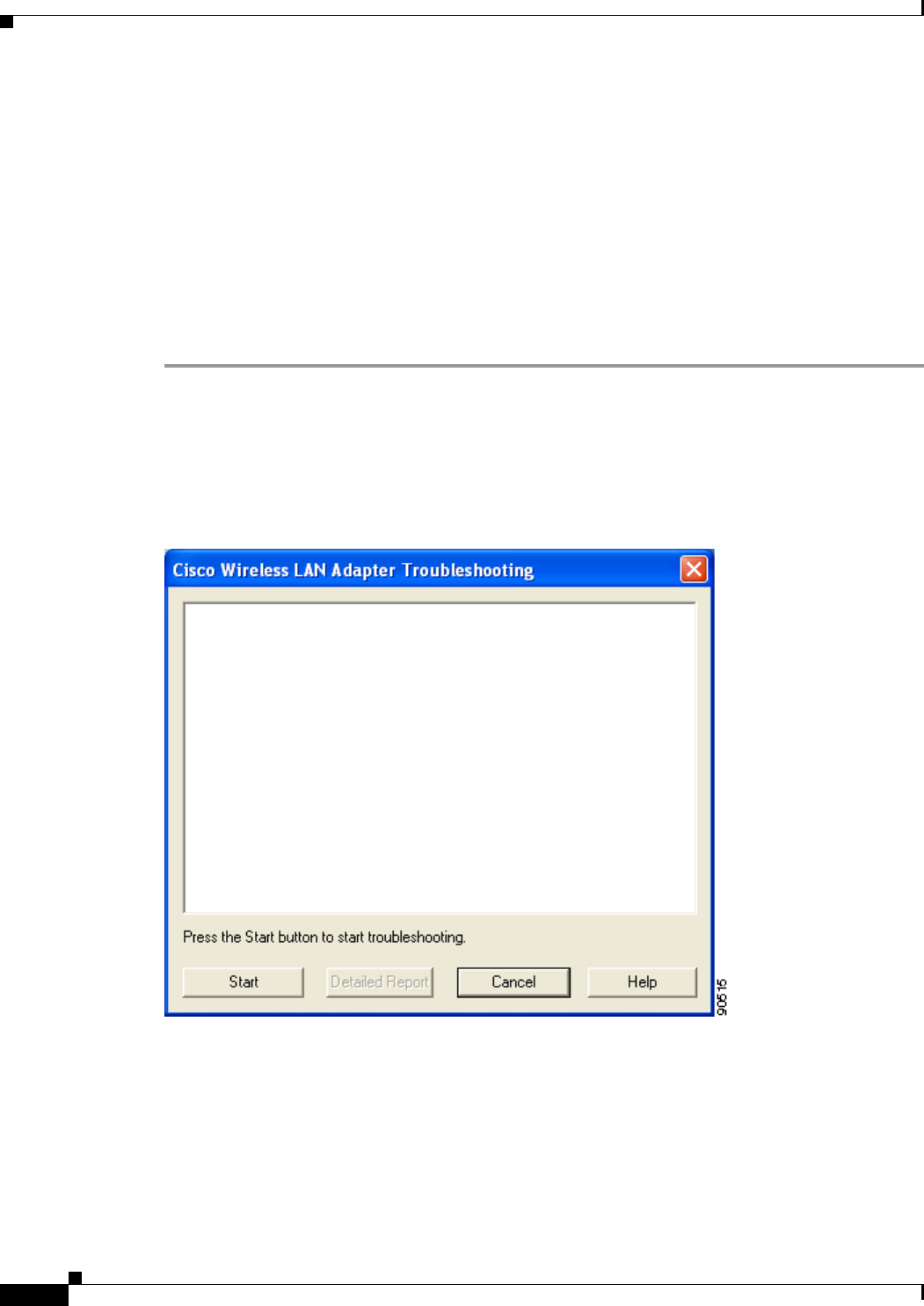
10-4
Cisco Aironet Wireless LAN Client Adapters Installation and Configuration Guide for Windows OL-1394-06
Chapter 10 Troubleshooting
Troubleshooting the Client Adapter
Using the Troubleshooting Utility
The Cisco Wireless LAN Adapter Troubleshooting Utility enables you to identify and resolve
configuration and association problems with your client adapter. It is meant to be used only when the
client adapter is in infrastructure mode as it assesses the connection between the adapter and an access
point.
Follow the instructions in one of the subsections below to use the utility to diagnose your client adapter’s
operation, save a detailed report to a text file, or access online help.
Diagnosing Your Client Adapter’s Operation
Step 1 Perform one of the following to activate the troubleshooting utility:
•Open ACU; select Troubleshooting from the Options drop-down menu.
•Right-click the ACM icon; select Troubleshooting from the pop-up menu.
The Cisco Wireless LAN Adapter Troubleshooting screen appears (see Figure 10-1).
Figure 10-1 Cisco Wireless LAN Adapter Troubleshooting Screen
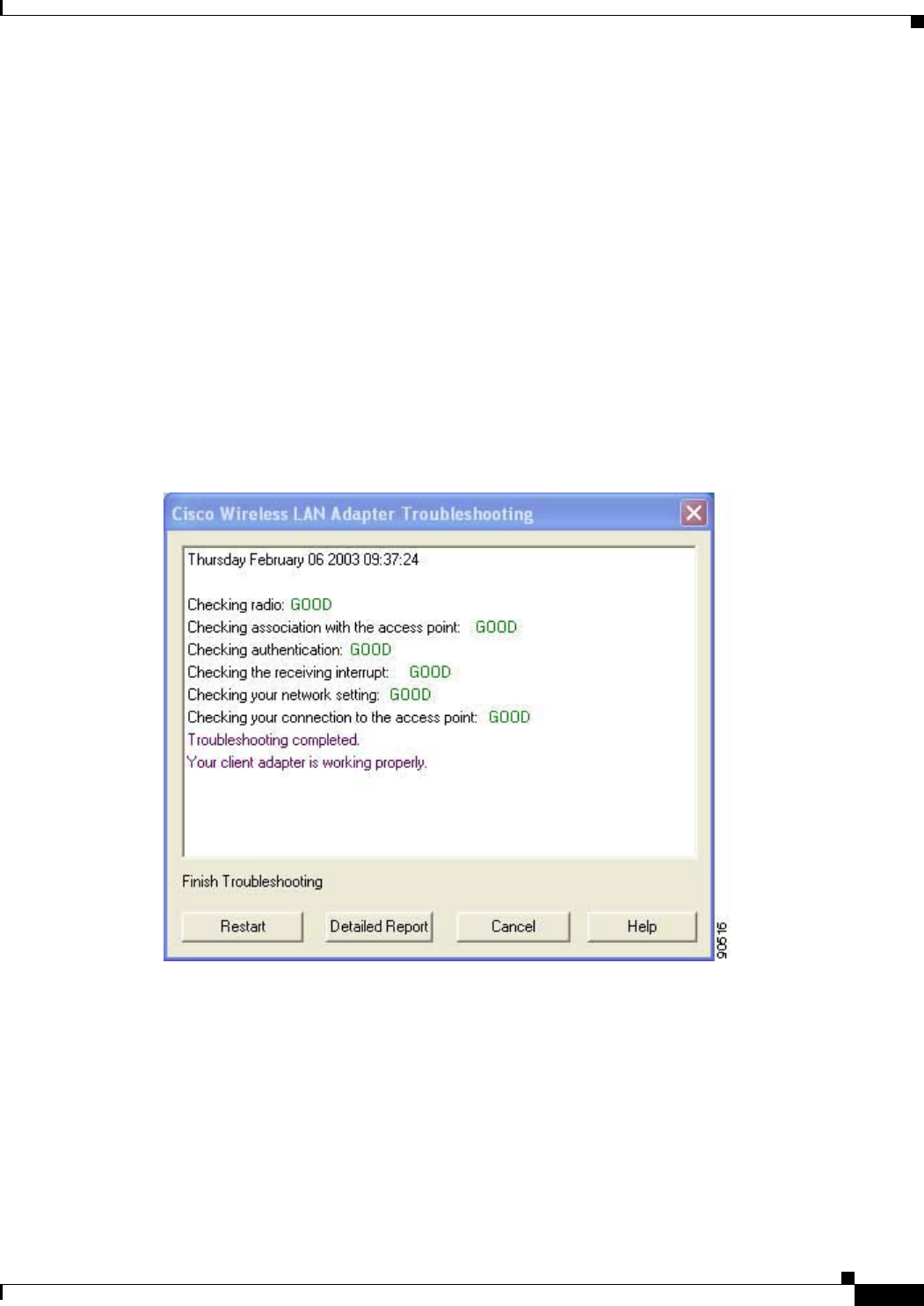
10-5
Cisco Aironet Wireless LAN Client Adapters Installation and Configuration Guide for Windows
OL-1394-06
Chapter 10 Troubleshooting Troubleshooting the Client Adapter
Step 2 Click Start. The utility performs the following series of eight tests to check the operation of your client
adapter and to pinpoint specific problems if they exist:
1. Checking driver installation
2. Checking client adapter insertion
3. Checking the client adapter’s radio (to see if it is turned on)
4. Checking the client adapter’s association to an access point
5. Checking authentication
6. Checking the receive interrupt
7. Checking network settings
8. Checking the client adapter’s connection to the access point
The utility runs until it completes successfully or a problem is discovered. It then displays the results
(see Figure 10-2).
Figure 10-2 Cisco Wireless LAN Adapter Troubleshooting Screen (with Test Results)

10-6
Cisco Aironet Wireless LAN Client Adapters Installation and Configuration Guide for Windows OL-1394-06
Chapter 10 Troubleshooting
Troubleshooting the Client Adapter
One of the following status messages appears for each test:
•GOOD—The test completed successfully.
•ERROR—The test failed because the client adapter is not configured properly to establish a
connection with an access point.
•WARNING—The test failed for one of the following reasons:
–
The utility is unable to access the client’s IP address. Either an incorrect IP address was entered,
or an IP address was not received from the DHCP server. Contact your system administrator.
–
The utility is unable to access the access point’s IP address. Contact your system administrator.
–
The exact cause cannot be determined. Contact your system administrator.
Note You can click Stop at any time to stop the testing process, or you can click Restart once the
testing process has stopped to run the test again.
Note If auto profile selection is enabled but the client adapter is not associated or authenticated, the
utility repeats the testing process continually so the client adapter can be tested with new
profiles.
Step 3 To view more detailed information, click Detailed Report. A report appears that explains the purpose
of each test and the results for your client adapter.
Note The report contains valuable information that, if necessary, could be used by TAC to analyze any
problems. Follow the instructions in the next section if you want to save the report to a text file.
Step 4 If a problem is discovered, the report provides some possible repair suggestions. Follow the repair
instructions carefully and run the troubleshooting utility again.
Step 5 Click Close to exit the detailed report.
Step 6 Click Cancel to exit the troubleshooting utility.
Saving the Detailed Report to a Text File
Follow the steps below to save the detailed troubleshooting report to your computer’s hard drive.
Step 1 Click Save on the detailed report screen. The Save As screen appears. A filename of the following format
appears automatically in the File name field: TSyymmddhhmm, where yymmddhhmm represents the date
and time that the troubleshooting utility was started. For example, TS0211211230 indicates that the
utility was started on 11/21/02 at 12:30.
Note You can change the filename by typing a new name in the File name field.

10-7
Cisco Aironet Wireless LAN Client Adapters Installation and Configuration Guide for Windows
OL-1394-06
Chapter 10 Troubleshooting Troubleshooting the Client Adapter
Step 2 Use the Save in box at the top of the screen to specify the location on your computer’s hard drive where
the file will be saved. The default location is My Documents.
Note If you specify a different location, the new location becomes the default location going forward.
Step 3 Click Save. The file is saved as a text file in the location specified.
Accessing Online Help
Follow the steps below to access general troubleshooting information about your client adapter.
Step 1 Click Help on the Cisco Wireless LAN Adapter Troubleshooting screen. An overview of the
troubleshooting utility appears.
Step 2 Click Help Topics at the top of the screen. From the Help Topics screen, you can access additional
information.
•To access information on specific topics, double-click Troubleshooting Tips on the Contents page,
the desired topic (such as Radio LEDs), and the desired subtopic (such as LED Error Condition
Messages).
•To search for a specific topic, click the Index tab, select an index entry, and click Display.
•To search for a specific word or phrase, click the Find tab, and follow the instructions in the Find
Setup Wizard window.
Step 3 Click Cancel to exit the Help Topics screen.
Client Adapter Recognition Problems
Note This section does not apply to mini PCI cards.
If your client adapter is not being recognized by your computer’s PCMCIA adapter, check your
computer’s BIOS and make sure that the PC card controller mode is set to PCIC compatible.
Note A computer’s BIOS varies depending on the manufacturer. For support on BIOS-related issues, consult
your computer’s manufacturer.

10-8
Cisco Aironet Wireless LAN Client Adapters Installation and Configuration Guide for Windows OL-1394-06
Chapter 10 Troubleshooting
Troubleshooting the Client Adapter
Resolving Resource Conflicts
Note This section does not apply to mini PCI cards.
If you encounter problems while installing your client adapter on a computer running a Windows
operating system, you may need to specify a different interrupt request (IRQ) or I/O range for the
adapter.
The default IRQ for the client adapter is IRQ 10, which may not work for all systems. Follow the steps
for your specific operating system to obtain an available IRQ.
During installation the adapter’s driver installation script scans for an unused I/O range. The installation
can fail if the I/O range found by the driver installation script is occupied by another device but not
reported by Windows. An I/O range might not be reported if a device is physically present in the system
but not enabled under Windows. Follow the steps for your specific operating system to obtain an
available I/O range.
Resolving Resource Conflicts in Windows 98, 98 SE, and Me
Step 1 Double-click My Computer,Control Panel, and System.
Step 2 Click the Device Manager tab.
Step 3 Double-click Network Adapters.
Step 4 Select the Cisco Systems Wireless LAN Adapter.
Step 5 Click the Properties button.
Step 6 In the General screen, the Device Status field indicates if a resource problem exists. If a problem is
indicated, click the Resources tab.
Step 7 Uncheck the Use automatic settings check box.
Step 8 Under Resource Settings or Resource Type, click Input/Output Range.
Step 9 Look in the Conflicting Device list at the bottom of the screen. If it indicates that the range is being used
by another device, click the Change Setting button.
Step 10 Scroll through the ranges in the Value dialog box and select one that does not conflict with another
device. The Conflict Information window at the bottom of the screen indicates if the range is already
being used.
Step 11 Click OK.
Step 12 Under Resource Settings or Resource Type, click Interrupt Request.
Step 13 Look in the Conflicting Device list at the bottom of the screen. If it indicates that the IRQ is being used
by another device, click the Change Setting button.
Step 14 Scroll through the IRQs in the Value dialog box and select one that does not conflict with another device.
The Conflict Information window at the bottom of the screen indicates if the IRQ is already being used.
Step 15 Click OK.
Step 16 Reboot your computer.

10-9
Cisco Aironet Wireless LAN Client Adapters Installation and Configuration Guide for Windows
OL-1394-06
Chapter 10 Troubleshooting Troubleshooting the Client Adapter
Resolving Resource Conflicts in Windows NT
Step 1 Select Start > Programs > Administrative Tools > Windows NT Diagnostics.
Step 2 Click the Resources tab.
Step 3 Click the IRQ button.
Step 4 The used IRQs are listed in numerical order along the left side of the Resources window. Write down the
number of an IRQ that is not being used; you will need it for Step 11.
Step 5 Click the I/O Port button.
Step 6 The used I/O ranges are listed in numerical order along the left side of the Resources window under
Address. Write down an I/O range that is not being used (for example, if range 0100-013F is followed
by 0170-0177 in the list, then 0140-0169 is an available range); you will need it for Step 13.
Step 7 Double-click My Computer,Control Panel, and Network.
Step 8 Click the Adapters tab and select the Cisco Aironet Wireless LAN Adapter.
Step 9 Click Properties.
Step 10 Select Interrupt under Property.
Step 11 Select the number of the unused interrupt from Step 4 in the Value drop-down box.
Step 12 Select IO Base Address under Property.
Step 13 Select a value that is within the unused range you determined in Step 6. For example, if your unused
range is 0140-0169, you could select 0150.
Step 14 Click OK.
Resolving Resource Conflicts in Windows 2000
Step 1 Double-click My Computer,Control Panel, and System.
Step 2 Click the Hardware tab and Device Manager.
Step 3 Double-click Network Adapters and the Cisco Systems Wireless LAN Adapter.
Step 4 In the General screen, the Device Status field indicates if a resource problem exists. If a problem is
indicated, click the Resources tab.
Step 5 Uncheck the Use automatic settings check box.
Step 6 Under Resource Settings or Resource Type, click Input/Output Range.
Step 7 Look in the Conflicting Device list at the bottom of the screen. If it indicates that the range is being used
by another device, click the Change Setting button.
Step 8 Scroll through the ranges in the Value dialog box and select one that does not conflict with another
device. The Conflict Information window at the bottom of the screen indicates if the range is already
being used.
Step 9 Click OK.

10-10
Cisco Aironet Wireless LAN Client Adapters Installation and Configuration Guide for Windows OL-1394-06
Chapter 10 Troubleshooting
Troubleshooting the Client Adapter
Step 10 Under Resource Settings or Resource Type, click Interrupt Request.
Step 11 Look in the Conflicting Device list at the bottom of the screen. If it indicates that the IRQ is being used
by another device, click the Change Setting button.
Step 12 Scroll through the IRQs in the Value dialog box and select one that does not conflict with another device.
The Conflict Information window at the bottom of the screen indicates if the IRQ is already being used.
Step 13 Click OK.
Step 14 Reboot your computer.
Resolving Resource Conflicts in Windows XP
Note These instructions assume you are using Windows XP’s classic view, not its category view.
Step 1 Double-click My Computer,Control Panel, and System.
Step 2 Click the Hardware tab and Device Manager.
Step 3 Under Network Adapters, double-click the Cisco Systems Wireless LAN Adapter.
Step 4 In the General screen, the Device Status field indicates if a resource problem exists. If a problem is
indicated, click the Resources tab.
Step 5 Uncheck the Use automatic settings check box.
Step 6 Under Resource Settings, click I/O Range.
Step 7 Look in the Conflicting Device list at the bottom of the screen. If it indicates that the range is being used
by another device, click the Change Setting button.
Step 8 Scroll through the ranges in the Value dialog box and select one that does not conflict with another
device. The Conflict Information window at the bottom of the screen indicates if the range is already
being used.
Step 9 Click OK.
Step 10 Under Resource Settings, click IRQ.
Step 11 Look in the Conflicting Device list at the bottom of the screen. If it indicates that the IRQ is being used
by another device, click the Change Setting button.
Step 12 Scroll through the IRQs in the Value dialog box and select one that does not conflict with another device.
The Conflict Information window at the bottom of the screen indicates if the IRQ is already being used.
Step 13 Click OK.
Step 14 Reboot your computer.

10-11
Cisco Aironet Wireless LAN Client Adapters Installation and Configuration Guide for Windows
OL-1394-06
Chapter 10 Troubleshooting Troubleshooting the Client Adapter
Problems Associating to an Access Point
Follow the instructions below if your client adapter fails to associate to an access point.
•If possible, move your workstation a few feet closer to an access point and try again.
•Make sure that the client adapter is securely inserted in your computer’s client adapter slot.
•If you are using a PCI client adapter, make sure that the antenna is securely attached.
•Make sure that the access point is turned on and operating.
•Check that all parameters are set properly for both the client adapter and the access point. These
include the SSID, EAP authentication, WEP activation, network type, channel, etc.
•Follow the instructions in the previous section to resolve any resource conflicts. If you are using
Windows NT, you may also want to try disabling the Ethernet port.
•If the client adapter still fails to establish contact, refer to the “Obtaining Technical Assistance”
section in the Preface for technical support information.
Problems Authenticating to an Access Point
If your client adapter is a 40-bit card and LEAP or EAP is enabled, the adapter can associate but not
authenticate to access points using 128-bit encryption. To authenticate to an access point using 128-bit
encryption, you have two options:
•Purchase a 128-bit client adapter. This is the most secure option.
•Disable static WEP for the client adapter and configure the adapter and the access point to associate
to mixed cells. This option presents a security risk because your data is not encrypted as it is sent
over the RF network.
Problems Connecting to the Network
After you have installed the appropriate firmware, driver, client utilities, and security modules, contact
your IS department if you have a problem connecting to the network. Proxy server, network protocols,
and further authentication information might be needed to connect to the network.
Prioritizing Network Connections (Windows 2000 and XP Only)
If your computer is running Windows 2000 or XP and more than one network adapter is enabled (such
as a Cisco Aironet client adapter and an Ethernet card), you can select which one to use by assigning a
priority to your network connections.
Note This procedure does not apply to Windows 98, 98 SE, NT, and Me because these operating systems allow
only one network adapter to be enabled at a time.

10-12
Cisco Aironet Wireless LAN Client Adapters Installation and Configuration Guide for Windows OL-1394-06
Chapter 10 Troubleshooting
Troubleshooting the Client Adapter
Follow the steps below to prioritize your network connections.
Step 1 Right-click the My Network Places icon on your desktop.
Step 2 Click Properties.
Step 3 Select the Advanced menu option at the top of the screen.
Step 4 Select Advanced Settings. Your network connections are listed in the Connections box on the Adapters
and Bindings tab.
Step 5 Use the arrows beside the Connections box to move the network connection that you want to use to the
top.
Step 6 Click OK.
Losing Association upon Resuming from Suspend Mode
(Windows NT and Mini PCI Cards Only)
Because Windows NT does not support resuming of mini PCI cards, your client adapter loses its
association to an access point upon resuming from suspend mode. If this occurs, restart your client
adapter to reassociate.
Parameters Missing from Profile Manager Screen
If some parameters are unavailable on the Profile Manager screen, your system administrator may have
used an administrative tool to deactivate these parameters. In this case, these parameters cannot be
selected.
Windows Wireless Network Connection Icon Shows Unavailable Connection
(Windows XP Only)
If your computer is running Windows XP and you configured your client adapter using ACU, the
Windows Wireless Network Connection icon in the Windows system tray may be marked with a red X
and show an unavailable connection even though a wireless connection exists. This condition is caused
by a conflict between ACU and Windows XP’s wireless network settings. Simply ignore the Windows
icon and use the ACM icon to check the status of your client adapter’s wireless connection.

10-13
Cisco Aironet Wireless LAN Client Adapters Installation and Configuration Guide for Windows
OL-1394-06
Chapter 10 Troubleshooting Error Messages
LEAP Login Screen Does Not Appear Before Windows Login Screen (Windows
98, 98 SE, and Me Only)
If you are using Windows 98, 98 SE, or Me and your client adapter is configured to use LEAP
authentication with an automatically prompted login, the LEAP login screen should appear before the
Windows screen after you reboot. If the Windows screen appears first, follow the steps below.
Step 1 On the Windows desktop, right-click the My Network Places icon.
Step 2 Click Properties.
Step 3 On the Network - Configuration screen, click the arrow on the right side of the Primary Network Logon
box.
Step 4 Select Cisco Aironet Wireless Logon and click OK.
Step 5 When prompted to restart your computer, click Yes.
Microsoft Hot Fix (Windows 98 and 98 SE Only)
When the LEAP security module is selected during installation on a Windows 98 or 98 SE device, a
Microsoft hot fix is also installed to fix two problems related to the use of LEAP. You can obtain a
description of this hot fix and the problems it resolves at the following Microsoft URL:
http://support.microsoft.com/support/kb/articles/Q247/8/05.asp
Note Only the English version of the hot fix is installed. Foreign language versions of these operating systems
require a hot fix specific to those languages. Contact Microsoft Product Support Services to obtain the
hot fix for languages other than English. Without the hot fix installed, you may be prompted to enter your
credentials at the Windows login prompt twice. To work around this problem, enter your login
credentials again.
Error Messages
This section provides a list of error messages that may appear during the installation, configuration, or
use of your client adapter. The error messages are divided into four sections (general, LEAP
authentication, PEAP authentication, and EAP-SIM authentication). The messages are listed in
alphabetical order within each section, and an explanation as well as a recommended user action are
provided for each message. Table 10-4 enables you to quickly locate the error messages you need.
Table 10-4 Locating Error Messages
Error Message Category Page Number
General 10-14
LEAP authentication 10-18
PEAP authentication 10-21
EAP-SIM authentication 10-26

10-14
Cisco Aironet Wireless LAN Client Adapters Installation and Configuration Guide for Windows OL-1394-06
Chapter 10 Troubleshooting
Error Messages
General Error Messages
This section lists general error messages that may appear at any time and are not related to authentication
attempts.
Error Message Bad Firmware Image File (filename)
Explanation The selected firmware file is corrupt and will not be sent to the client adapter.
Recommended Action Select a different firmware file and try to load it.
Error Message Card Removed at xx:xx
Explanation The client adapter was ejected from the computer.
Recommended Action Reinsert the client adapter if you wish to resume wireless communications.
Error Message An error occurred while trying to make the selected profile active.
Explanation An error occurred when you selected a profile in ACM.
Recommended Action Check the profile’s configuration parameters in ACU or select a new profile.
Error Message Error Reading filename
Explanation A problem occurred while the computer was reading the firmware file from the disk.
Recommended Action Re-copy the firmware file to a floppy disk or to your computer’s hard drive and
try to load it again or select a different firmware file and try to load it.
Error Message Error Writing to Flash Memory
Explanation A problem occurred while the firmware was being flashed.
Recommended Action Eject the client adapter and reinsert it. If the client adapter functions properly,
the firmware was flashed successfully. If the client adapter does not function or functions improperly,
your client adapter may need to be returned for service. Refer to the “Technical Assistance Center”
section in the Preface for information on contacting TAC.
Error Message Firmware Incompatible with Hardware
Explanation The selected firmware file does not work with the client adapter.
Recommended Action Select a different firmware file and try to load it.

10-15
Cisco Aironet Wireless LAN Client Adapters Installation and Configuration Guide for Windows
OL-1394-06
Chapter 10 Troubleshooting Error Messages
Error Message Firmware Upgrade Failed
Explanation A problem occurred while the firmware was being flashed.
Recommended Action Eject the client adapter and reinsert it. If the client adapter functions properly,
the firmware was flashed successfully. If the client adapter does not function or functions improperly,
your client adapter may need to be returned for service. Refer to the “Technical Assistance Center”
section in the Preface for information on contacting TAC.
Error Message The installation will complete and applications will be installed when
a wireless LAN client adapter is inserted. If an adapter is already inserted,
remove and reinsert the adapter or reboot the machine.
Explanation The installation program was most likely run without a client adapter inserted in the
computer.
Recommended Action Insert a client adapter into your computer’s client adapter slot. The installation
program will then complete. If a client adapter was already inserted in your computer, eject and
reinsert the adapter or reboot your computer.
Error Message LEAP support has not been installed on this computer. You will not be
able to authenticate with this or any other profile configured to use LEAP.
Explanation A LEAP profile was selected for use in ACM, but the LEAP security module was not
selected during installation. Therefore, the client adapter will not be able to authenticate using this
profile (or any other profile that is configured for LEAP).
Recommended Action Run the installation program again and enable the LEAP security module.
Error Message Maximum power save mode will be temporarily disabled while you are
running this application!
Explanation The client adapter cannot be run in Max PSP mode while ACU is running.
Recommended Action No user action is required. The client adapter automatically runs in Fast PSP
mode while ACU is running.
Error Message No Cisco Aironet client adapters have been installed on this computer.
Explanation ACM started but found no installed client adapters.
Recommended Action Follow the instructions in Chapter 3 to install a client adapter.
Error Message No Wireless LAN Client Adapters Found
Explanation A client adapter is not inserted in the computer.
Recommended Action Insert a client adapter if you wish to start wireless communications.

10-16
Cisco Aironet Wireless LAN Client Adapters Installation and Configuration Guide for Windows OL-1394-06
Chapter 10 Troubleshooting
Error Messages
Error Message No Wireless LAN Client Adapters Installed!
Explanation An attempt was made to start ACU without a client adapter being inserted in the
computer. ACU cannot execute if a client adapter is not inserted because it needs to be able to read
from and write to the adapter.
Recommended Action Insert a client adapter and start ACU.
Error Message Please close ACU in order to use it with the Wireless LAN Adapter you
selected using the System Tray Icon.
Explanation Only one instance of ACU can be running at a time. However, an attempt was made to
activate ACU for a second client adapter when ACU was already running.
Recommended Action Click OK, close ACU, and then activate ACU for the desired adapter.
Error Message This program is already running.
Explanation ACM started when another instance of ACM was already running.
Recommended Action No action is required. The new instance of ACM exits.
Error Message Reauthenticate Failed
Explanation The Reauthenticate option was selected from the Commands drop-down menu in ACU,
but the reauthentication attempt failed.
Recommended Action Re-enter your username and password and try to authenticate again or select
another EAP profile.
Error Message Restarting the client adapter will cause you to lose your network
connection. Are you sure you want to restart your client adapter?
Explanation The Restart Card option was selected from the Commands drop-down menu in ACU,
which may cause you to lose your network connection.
Recommended Action If you want to reinitialize your client adapter, click Yes. Otherwise, click No.
Error Message Unable to Open filename
Explanation The selected firmware file cannot be found.
Recommended Action Re-copy the firmware file to a floppy disk or to your computer’s hard drive and
try to load it again or select a different firmware file and try to load it.

10-17
Cisco Aironet Wireless LAN Client Adapters Installation and Configuration Guide for Windows
OL-1394-06
Chapter 10 Troubleshooting Error Messages
Error Message Wireless Connection Unavailable. (Windows XP only)
Explanation ACU was used to configure the client adapter on Windows XP, but the Use Windows to
configure my wireless network settings check box in Windows XP is checked. This message
appears even if the client adapter is associated to an access point.
Recommended Action Uncheck the Use Windows to configure my wireless network settings check
box in Windows XP to force Windows to display the correct status.
Error Message You cannot run a link test because your client adapter is not
associated.
Explanation An attempt was made to run a link test while the client adapter was not associated to an
access point or other wireless device.
Recommended Action Run the link test after the client adapter is associated to an access point or
another wireless device.
Error Message You cannot run a link test because your client adapter’s radio is
turned off.
Explanation An attempt was made to run a link test while the client adapter’s radio was off.
Recommended Action Turn on the client adapter’s radio by selecting Radio On from the Commands
drop-down menu in ACU; then run the link test.
Error Message You must specify an IP address before running a link test.
Explanation An attempt was made to run a link test although the IP address of the access point or other
wireless device with which to test the RF link was not specified.
Recommended Action In the Linktest screen’s IP Address of Access Point field, enter the IP address
of the access point or other wireless device with which you want to test the RF link.
Error Message You need to be an administrator or a user with administrative rights
to install Aironet Client Utility. Please log on as a different user and try again.
Explanation A non-administrative user attempted to install ACU. The ACU installation process
terminates.
Recommended Action Log on as a different user and attempt the installation process again.
Error Message Your Wireless LAN Adapter is not inserted!
Explanation One of two conditions is present: 1) a client adapter is not inserted in your computer or
2) ACU was started with one variety of client adapter inserted (such as a PCM342), the adapter was
subsequently ejected, and another variety was inserted (such as a PCM352).
Recommended Action Perform one of the following: 1) insert a client adapter into your computer if
one is not present or 2) shut down ACU and restart it.

10-18
Cisco Aironet Wireless LAN Client Adapters Installation and Configuration Guide for Windows OL-1394-06
Chapter 10 Troubleshooting
Error Messages
LEAP Authentication Error Messages
This section lists error messages that may occur during LEAP authentication.
Error Message The client adapter doesn’t support LEAP. Please make sure that you have
installed the correct client adapter and updated your firmware.
Explanation LEAP authentication failed because the client adapter’s firmware does not support
LEAP.
Recommended Action Make sure that you have installed the correct client adapter and are using the
firmware included in the Install Wizard file.
Error Message The client adapter doesn’t support WEP, so LEAP cannot be run. Please
make sure that you have installed the correct client adapter and purchased WEP
support.
Explanation LEAP authentication failed because the client adapter’s firmware does not support WEP.
Recommended Action Make sure that you have installed the correct client adapter and are using the
firmware included in the Install Wizard file.
Error Message The combination of domain name and user name exceeds the maximum number
of characters (32) that LEAP supports. Please uncheck Include Windows Logon Domain
with User Name in ACU or use shorter names.
Explanation The combination of characters entered for the username and domain name in the
Windows login screen or the LEAP login screen exceeds the maximum number supported by LEAP,
which is 32.
Recommended Action Perform one of the following:
–
Uncheck the Include Windows Logon Domain with User Name check box in the LEAP
Settings screen of ACU.
–
Enter a set of credentials (username, password, and domain name) with fewer characters.
Error Message The current profile is not configured for LEAP.
Explanation The Manual LEAP Login option was selected in ACU, but the active profile is not
configured for LEAP. The LEAP authentication process aborts.
Recommended Action If you want the client adapter to LEAP authenticate, select a profile that is
configured for LEAP.

10-19
Cisco Aironet Wireless LAN Client Adapters Installation and Configuration Guide for Windows
OL-1394-06
Chapter 10 Troubleshooting Error Messages
Error Message The LEAP password entered exceeds the maximum number of characters (32)
that LEAP supports. Please use a shorter password.
Explanation The password that was entered exceeds the maximum number of characters supported by
LEAP, which is 32.
Recommended Action Re-enter the password, making sure it contains fewer than 32 characters.
Error Message The xxx profile was disabled because LEAP authentication failed during
your last logoff. You can re-enable the profile by selecting the Reauthenticate
option.
Explanation A profile that was configured for LEAP failed an authentication attempt during the last
logoff process and was disabled. Because error messages cannot be displayed during the logoff
process, this message appears after the next logon.
Recommended Action Select Reauthenticate from ACM or the Commands drop-down menu in ACU
to re-enable the profile.
Error Message The profile will be disabled until you select the Reauthenticate
option, Windows restarts, or the card is ejected and reinserted. Are you sure?
Explanation The username and password for your current profile have expired or are no longer valid.
When the LEAP login screen appeared, prompting you to enter your new username and password,
you selected Cancel. The profile was disabled to prevent accidental authentication attempts in the
future.
Recommended Action Click No, enter your new username and password when the LEAP login screen
reappears, and click OK. The client adapter should authenticate using your new credentials. If the
profile uses saved credentials, edit the profile in ACU by changing the username and password on the
LEAP Settings screen and save your changes. (If you click Yes, the profile is disabled until you select
Reauthenticate from ACM or the Commands drop-down menu in ACU, reboot your system, or eject
and reinsert the card.)
Caution If your backend server is set to allow only a limited number of failed authentication attempts, your user
account may be locked if you continue trying with an invalid set of user credentials.
Error Message A recently installed program has disabled the Welcome screen and Fast
User Switching. To restore these features, you must uninstall the program. The
following file name might help you identify the program that made the change:
cswGina.dll. (Windows XP only)
Explanation The LEAP security module was selected during installation on a Windows XP computer;
then the Change the way users log on or off option was selected under Windows XP’s User Accounts.
Recommended Action If the LEAP security module is selected during installation, you cannot use
Windows XP’s fast user switching feature. If you want to use fast user switching and do not want to
use LEAP, you must run the installation program again and deselect the LEAP security module.

10-20
Cisco Aironet Wireless LAN Client Adapters Installation and Configuration Guide for Windows OL-1394-06
Chapter 10 Troubleshooting
Error Messages
Error Message The saved user name and password entered for this profile are no longer
valid and have failed the LEAP authentication process. Please enter a new user
name and password. Remember to change them permanently in the profile using the
ACU Profile Manager.
Explanation The username and password for your current profile, which uses saved credentials, have
expired or are no longer valid; therefore, your client adapter is unable to LEAP authenticate.
Recommended Action When the LEAP login screen appears, enter your new username and password
and click OK. The client adapter should authenticate using your new credentials. Then edit the
profile in ACU by changing the username and password on the LEAP Settings screen and save your
changes.
Error Message To run LEAP successfully, you will have to apply Microsoft Q241052
Update for the language version of your operating system as documented on
http://support.microsoft.com/support/kb/articles/Q247/8/05.asp. Please contact
Microsoft Product Support Services to obtain the fix.
Explanation When the LEAP security module is selected during installation on a Windows 98 or 98
SE device, a Microsoft hot fix is also installed to fix two problems related to the use of LEAP.
However, only the English version of the hot fix is installed. Foreign language versions of these
operating systems require a hot fix specific to those languages.
Recommended Action Contact Microsoft Product Support Services to obtain the hot fix for languages
other than English. Without the hot fix installed, you may be prompted to enter your credentials at
the Windows login prompt twice. To work around this problem, enter your login credentials again.
Error Message Unable to LEAP authenticate. Please make sure you have entered the
correct user name and password and try again.
Explanation LEAP authentication failed.
Recommended Action Perform one of the following:
–
Re-enter the LEAP username and password or cancel the LEAP authentication.
–
To start another LEAP authentication process, select Reauthenticate from ACM or the
Commands drop-down menu in ACU, log off and log in again, or select Manual LEAP Login
from the Commands drop-down menu in ACU.
Error Message Unable to LEAP authenticate in the specified amount of time. The
network infrastructure might be down. You may also want to increase the LEAP
timeout value for this profile.
Explanation The client adapter was unable to LEAP authenticate within the amount of time specified
by the LEAP authentication timeout value.
Recommended Action Increase the LEAP authentication timeout value on the LEAP Settings screen.
Then re-enter the LEAP username and password.

10-21
Cisco Aironet Wireless LAN Client Adapters Installation and Configuration Guide for Windows
OL-1394-06
Chapter 10 Troubleshooting Error Messages
Error Message The user name and password entered are no longer valid and have failed
the LEAP authentication process. Please enter a new user name and password.
Explanation The username and password for your current profile have expired or are no longer valid;
therefore, your client adapter is unable to LEAP authenticate.
Recommended Action When the LEAP login screen appears, enter your new username and password
and click OK. The client adapter should authenticate using your new credentials.
Error Message The user name entered is not valid or exceeds the maximum number of
characters (32) that LEAP supports.
Explanation The username that was entered is not valid or exceeds the maximum number of
characters supported by LEAP, which is 32.
Recommended Action Re-enter the username, making sure it contains fewer than 32 characters.
PEAP Authentication Error Messages
This section lists error messages that may occur during PEAP authentication. The messages are divided
into six subsections based on the type of database that is used with PEAP. Use Table 10-5 to quickly
locate the error messages for your database.
For All PEAP-Supported Databases
Error Message PEAP failed initialization. Please make sure that PEAP is installed
correctly and Trusted Root Certificate Authority certificate is installed
correctly.
Explanation The PEAP authentication process failed during initialization, most likely because the
specified root certificate is missing from the system.
Recommended Action Make sure that PEAP and the Trusted Root Certificate Authority certificate are
installed correctly.
Table 10-5 Locating PEAP Authentication Error Messages
Error Message Category Page Number
All PEAP-supported databases 10-21
Windows NT or 2000 domain databases 10-22
All OTP databases 10-23
OTP databases using Secure Computing
SofToken version 1.3 10-24
OTP databases using Secure Computing
SofToken II version 2.0 10-25
OTP databases using RSA SecurID version 2.5 10-26

10-22
Cisco Aironet Wireless LAN Client Adapters Installation and Configuration Guide for Windows OL-1394-06
Chapter 10 Troubleshooting
Error Messages
Error Message You have connected to a server that is signed by Root Certification
Authority xxx, which is different than the specified trusted CA. Do you want to
accept this connection? Warning: Connecting to a server signed with untrusted CA
might compromise your security.
Explanation The client adapter has established a connection to a certificate server other than the
specified trusted CA.
Recommended Action If you want the client adapter to connect to this server even though it may
present a security risk, click Yes. Otherwise, click No.
Error Message You have connected to server xxx. Do you want to accept the connection?
Warning: Connecting to an unsecured server might compromise your security.
Explanation The client adapter has established a connection to the server specified.
Recommended Action If you want the client adapter to connect to this server even though it may
present a security risk, click Yes. Otherwise, click No.
For Windows NT or 2000 Domain Databases
Error Message New Password and Confirm New Password entered do not match. Please try
it again.
Explanation You entered different values in the New Password and Confirm New Password fields on
the Change Password screen. They must be identical.
Recommended Action Re-enter your new password in both fields.
Error Message The old password you supplied doesn’t match what you entered
previously. Please try it again.
Explanation The password entered in the Old Password field on the Change Password screen does not
match the password that was used previously.
Recommended Action Re-enter your old password in the Old Password field.
Error Message Your domain password has been successfully changed on the server. To
synchronize any Windows password that might be locally cached, you must also
manually change the password in Windows.
Explanation You have successfully changed your domain password using the Static Password screen.
However, if you also have a locally cached Windows password, you must manually change it to
synchronize it with your domain password.
Recommended Action Press Ctrl-Alt-Delete, select Change Password, and enter your old password
once and your new password twice.

10-23
Cisco Aironet Wireless LAN Client Adapters Installation and Configuration Guide for Windows
OL-1394-06
Chapter 10 Troubleshooting Error Messages
For All OTP Databases
Error Message Failed to change your PIN. Error code xxx. Run Software Token program
to fix it.
Explanation Your attempt to change your PIN using the Change PIN screen failed due to a problem
with the software token program.
Recommended Action Run the software token program and then try to change your PIN again.
Error Message Invalid PIN. Please try again.
Explanation The PIN that you entered is invalid.
Recommended Action Re-enter your PIN.
Error Message New PIN and Confirm New PIN do not match. Please try them again.
Explanation You entered different values in the New PIN and Confirm New PIN fields on the Change
PIN screen. They must be identical.
Recommended Action Re-enter your new PIN in both fields.
Error Message New PIN is invalid. Please try it again.
Explanation The PIN that you entered in the New PIN field on the Change PIN screen is invalid.
Recommended Action Re-enter your new PIN.
Error Message The old PIN you supplied is invalid. Please try it again.
Explanation The old PIN that you entered on the Change PIN screen is invalid.
Recommended Action Re-enter your old PIN.
Error Message Please check either Support Hardware Token or Support Software Token.
One of them must be selected.
Explanation While the client adapter was being configured for PEAP authentication, the One Time
Password option was selected on the Generic Token Card Properties screen, but neither the Support
Hardware Token nor the Support Software Token option was selected.
Recommended Action Check either the Support Hardware Token check box or the Support
Software Token check box or both.

10-24
Cisco Aironet Wireless LAN Client Adapters Installation and Configuration Guide for Windows OL-1394-06
Chapter 10 Troubleshooting
Error Messages
Error Message Your PIN has expired. Please change your PIN.
Explanation The PIN that you have been using to authenticate has expired.
Recommended Action Follow the instructions in the “After Your PIN Expires (OTP Databases Only)”
section on page 6-19 to change your PIN.
For OTP Databases Using Secure Computing SofToken Version 1.3
Error Message Could not find SofToken.exe in the program path specified. Please make
sure SofToken is installed correctly and the correct program path is entered.
Explanation SofToken.exe is not located at the path you entered on the Generic Token Card Properties
screen.
Recommended Action Make sure that SofToken is installed correctly; then re-enter the program path.
Error Message Error getting data from SofToken server. Please make sure SofToken is
installed correctly and the correct program path is entered.
Explanation An error occurred while attempting to get data from the SofToken server.
Recommended Action Make sure that SofToken is installed correctly and the correct program path is
entered.
Error Message Initialization of SofToken library failed. Please make sure SofToken
is installed correctly and the correct program path is entered.
Explanation An error occurred with the SofToken program.
Recommended Action Make sure that SofToken is installed correctly and the correct program path is
entered.
Error Message The program path entered exceeds the maximum length allowed (255).
Explanation The program path entered on the Generic Token Card Properties screen contains more
characters than the field allows.
Recommended Action Re-enter the path using a maximum of 255 characters. If necessary, move
SofToken.exe to a directory with a shorter path.
Error Message Program path must be specified for SofToken Version 1.3.
Explanation Secure Computing SofToken Version 1.3 was selected from the Supported Type
drop-down box on the Generic Token Card Properties screen, but the SofToken program path was not
entered.
Recommended Action Enter the path to the SofToken program in the SofToken Program Path field.

10-25
Cisco Aironet Wireless LAN Client Adapters Installation and Configuration Guide for Windows
OL-1394-06
Chapter 10 Troubleshooting Error Messages
Error Message SofToken is not set up to allow processing from SofToken calls. Calls
have been disabled from the SofToken Manager, the SofToken program does not have
any valid users yet, or the last person to use SofToken was not initialized
correctly.
Explanation The SofToken program is not set up to process SofToken API calls.
Recommended Action Make sure that SofToken is configured to enable SofToken calls and verify that
you are set up as a valid user.
Error Message Unable to launch SofToken.exe. Please make sure SofToken is installed
correctly and the correct program path is entered.
Explanation An error occurred with the SofToken program.
Recommended Action Make sure that SofToken is installed correctly and the correct program path is
entered.
Error Message Unable to load SofToken library. Please make sure that SofToken is
installed correctly.
Explanation An error occurred with the SofToken program.
Recommended Action Make sure that SofToken is installed correctly and the correct program path is
entered.
For OTP Databases Using Secure Computing SofToken II Version 2.0
Error Message Error getting the OTP password for the user. Run SofToken II to ensure
the user is set up correctly.
Explanation An error occurred while attempting to obtain the OTP password for the user.
Recommended Action Run the SofToken II program to make sure that the user is set up properly.
Error Message Failed to load data from the OTP database for User ID: xxxx. Run
SofToken II to ensure the user is set up correctly.
Explanation An error occurred while attempting to load data from the OTP database for the specified
user.
Recommended Action Run the SofToken II program to make sure that the specified user is set up
properly.
Error Message Here is the hint you entered when you created your PIN: xxxx.
Explanation You entered an invalid PIN.
Recommended Action Use the hint to help you remember your PIN; then re-enter it.

10-26
Cisco Aironet Wireless LAN Client Adapters Installation and Configuration Guide for Windows OL-1394-06
Chapter 10 Troubleshooting
Error Messages
Error Message Unable to load SofToken II library. Please make sure that SofToken II
is installed correctly.
Explanation An error occurred with the SofToken II program.
Recommended Action Make sure that SofToken II is installed correctly.
For OTP Databases Using RSA SecurID Version 2.5
Error Message Error getting password from RSA SecurID Software Token.
Explanation An error occurred while attempting to obtain the user password from the RSA SecurID
program.
Recommended Action Run the RSA SecurID program to make sure that the user is set up properly.
Error Message Unable to load RSA library. Please make sure that RSA SecurID Software
Token is installed correctly.
Explanation An error occurred with the RSA SecurID program.
Recommended Action Make sure that RSA SecurID is installed correctly.
Error Message Unable to open RSA Token service.
Explanation An error occurred with the RSA SecurID program.
Recommended Action Make sure that RSA SecurID is installed correctly.
EAP-SIM Authentication Error Messages
This section lists error messages that may occur during EAP-SIM authentication.
Error Message Client_handleResponseIdentity error.
Explanation When asked to perform an authentication, the EAP-SIM supplicant encountered an error
retrieving your network username from the SIM card. This error may occur if an invalid SIM card
(such as one intended for mobile phone use) is inserted in the card reader or if Windows encounters
a processing error.
Note The eight-digit hexadecimal error code in the message may assist technical support in
troubleshooting your problem.
Recommended Action Make sure that you have a valid SIM card that was provided to you for wireless
network access and that it is inserted properly. If the problem occurs several times in a row, reboot
your computer.

10-27
Cisco Aironet Wireless LAN Client Adapters Installation and Configuration Guide for Windows
OL-1394-06
Chapter 10 Troubleshooting Error Messages
Error Message For the changes to take effect, please restart your WLAN card (or your
computer) NOW.
Explanation The changes you made on the SIM Authentication Properties screen can take effect only
if you perform a complete reauthentication. Otherwise, your wireless network connection may
appear to be stuck in the “Validating identity” state.
Recommended Action Turn off your client adapter’s radio, wait a few seconds, and then turn the radio
back on. Refer to the “Turning Your Client Adapter’s Radio On or Off” section on page 9-15 for
instructions.
Error Message GetUserPin returned error.
Explanation Windows encountered an error while prompting for or retrieving the PIN.
Note The eight-digit hexadecimal error code in the message may assist technical support in
troubleshooting your problem.
Recommended Action Wait until the system tries to authenticate the client adapter again
(approximately 30 to 60 seconds) and enter a valid PIN. Do not click Cancel or otherwise interfere
with the normal operation of Windows. If the problem persists, reboot your computer.
Error Message Maximum length of PIN is 8 characters.
Explanation You tried to enter a PIN that is longer than eight characters. SIM card PINs are restricted
to a maximum length of eight alphanumeric characters.
Recommended Action Delete one or more characters from the PIN field or delete all of the characters
you entered and retype the complete PIN.
Error Message Network authentication aborted.
Explanation When you were asked to enter a PIN, you clicked the Cancel button and cancelled the
authentication process. The EAP-SIM supplicant will not attempt to authenticate to the network.
Note The system will try to authenticate automatically within 30 to 60 seconds.
Recommended Action If you want to authenticate to the network and establish a wireless network
connection, enter the valid PIN for your SIM card. If you do not want to establish a connection,
consider turning off or ejecting the client adapter; otherwise, the system will reprompt you every 30
to 60 seconds.

10-28
Cisco Aironet Wireless LAN Client Adapters Installation and Configuration Guide for Windows OL-1394-06
Chapter 10 Troubleshooting
Error Messages
Error Message Network rejected user authentication.
Explanation The service provider’s network has rejected your authentication attempt. This is most
likely due to an expired or invalid SIM card or an invalidated account. However, it could also occur
if the service provider at your current location does not allow access to the network for subscribers
of your service provider.
Recommended Action Make sure that your account is in good standing and that you have a valid SIM
card. Switch to a SIM card that is valid at the current location and try again.
Error Message Please check your smartcard reader and insert your SIM card.
Explanation When asked to perform an authentication, the EAP-SIM supplicant could not get the
smartcard reader to initialize within a reasonable time (that is, 90 seconds for the first try and 5
minutes for subsequent tries). Most likely, the reader is not plugged in correctly, or the computer no
longer recognizes it.
Note The eight-digit hexadecimal error code in the message may assist technical support in
troubleshooting your problem.
Recommended Action Follow the steps below.
Step 1 Install a smartcard reader if you have not done so.
Step 2 If a reader is installed, make sure that it is inserted completely into the PCMCIA slot (PCMCIA model)
or that the connector cable is inserted properly into the serial or USB connector (serial/USB port model).
Step 3 Make sure that the system recognizes your reader. It should be listed under Smart card readers in
Windows device manager. If your reader is not listed, eject and reinsert the reader (PCMCIA model) or
disconnect and reconnect the cable (serial/USB port model).
Step 4 If the computer still does not recognize your reader, reboot the computer with the reader installed.
Error Message Please check your smartcard reader and SIM card, then try again.
Explanation The EAP-SIM supplicant has detected a general smartcard-related error (that is, not one
of the specific errors included in this section) and has aborted the authentication process.
Note The eight-digit hexadecimal error code in the title may assist technical support in
troubleshooting your problem.
Recommended Action Follow the steps below.
Step 1 Make sure that your smartcard reader is installed properly and that your SIM card is inserted properly.
Step 2 Follow the Recommended Action instructions for the “Please check your smartcard reader and try again”
error message below.
Step 3 Follow the Recommended Action instructions for the “Please insert your SIM card and try again” error
message on page 10-30.

10-29
Cisco Aironet Wireless LAN Client Adapters Installation and Configuration Guide for Windows
OL-1394-06
Chapter 10 Troubleshooting Error Messages
Step 4 If you are sure that the reader and card are both inserted properly, wait until the system tries to
authenticate again. This should occur within 30 to 60 seconds.
Caution Never remove your SIM card until the system has completed the authentication process.
Step 5 If the problem persists, try restarting the client adapter or rebooting your computer.
Error Message Please check your smartcard reader and try again.
Explanation Windows could not detect a smartcard reader in the system. You may not have installed
a reader, or this may happen after resuming Windows from suspend or hibernation.
Recommended Action Follow the steps below.
Step 1 Install a smartcard reader if you have not done so.
Step 2 If a reader is installed, make sure that it is inserted completely into the PCMCIA slot (PCMCIA model)
or that the connector cable is inserted properly into the serial or USB connector (serial/USB port model).
Step 3 Make sure that the system recognizes your reader. It should be listed under Smart card readers in
Windows device manager. If your reader is not listed, eject and reinsert the reader (PCMCIA model) or
disconnect and reconnect the cable (serial/USB port model).
Step 4 If the computer still does not recognize your reader, reboot the computer with the reader installed.
Error Message Please contact your service provider to unblock your card.
Explanation You have exceeded your SIM card’s retry limit by entering too many incorrect PINs in a
row.
Recommended Action Contact your service provider’s customer service center to get the card
unblocked. The phone number may be printed on your SIM card.
Error Message Please do not switch SIM cards after authenticating.
Explanation The EAP-SIM supplicant has detected that the network username stored on the currently
inserted SIM card differs from the username that was used in a previous authentication. Due to this
mismatch, authentication may fail.
Recommended Action If the currently inserted SIM card is recognized by the network, authentication
may succeed or fail, depending on the network configuration. If your client adapter is authenticated,
you may ignore this message. Otherwise, replace the SIM card currently inserted with the SIM card
that was used for your first authentication and wait until the system tries to authenticate your client
adapter again (approximately 30 to 60 seconds). You may also restart the client adapter or reboot your
computer with the new SIM card to try again.

10-30
Cisco Aironet Wireless LAN Client Adapters Installation and Configuration Guide for Windows OL-1394-06
Chapter 10 Troubleshooting
Error Messages
Error Message Please enter a PIN (1 to 8 characters).
Explanation When you were prompted for a PIN, you clicked the OK button before entering the PIN.
Recommended Action Enter the PIN required to access your SIM card. If you do not want to
authenticate at this time or do not have your PIN available, click the Cancel button instead.
Error Message Please insert your SIM card and try again.
Explanation The system could not detect a SIM card in the smartcard reader.
Recommended Action Make sure that your SIM card is inserted into the reader properly. It should be
inserted into the reader all the way and not into the empty space in the PCMCIA slot. Try removing
and reinserting the card. You should feel it latch into place and notice a slight resistance when
attempting to remove it.
Error Message SimOpenSession error.
Explanation When asked to retrieve your network username, the EAP-SIM supplicant was unable to
establish a connection to the SIM card. This can occur if a SIM card is not inserted in the reader, the
SIM card is not inserted properly, or the wrong SIM card is inserted.
Recommended Action Make sure that you are using a valid SIM card (that is, the SIM card provided
to you for wireless network access, not a SIM card intended for mobile phone use). If that does not
correct the error, make sure that your SIM card is inserted into the reader properly. It should be
inserted into the reader all the way and not into the empty space in the PCMCIA slot. Try removing
and reinserting the card. You should feel it latch into place and notice a slight resistance when
attempting to remove it.
Error Message Time-out waiting for smartcard reader initialization.
Explanation When asked to perform an authentication, the EAP-SIM supplicant could not get the
smartcard reader to initialize within a reasonable time (90 seconds for the first try and 5 minutes for
subsequent tries). Most likely, the reader is not plugged in correctly, or the computer no longer
recognizes it.
Note The eight-digit hexadecimal error code in the message may assist technical support in
troubleshooting your problem.
Recommended Action Follow the steps below.
Step 1 Install a smartcard reader if you have not done so.
Step 2 If a reader is installed, make sure that it is inserted completely into the PCMCIA slot (PCMCIA model)
or that the connector cable is inserted properly into the serial or USB connector (serial/USB port model).

10-31
Cisco Aironet Wireless LAN Client Adapters Installation and Configuration Guide for Windows
OL-1394-06
Chapter 10 Troubleshooting Error Messages
Step 3 Make sure that the system recognizes your reader. It should be listed under Smart card readers in
Windows device manager. If your reader is not listed, eject and reinsert the reader (PCMCIA model) or
disconnect and reconnect the cable (serial/USB port model).
Step 4 If the computer still does not recognize your reader, reboot the computer with the reader installed.
Error Message Wrong PIN entered (X tries left).
Explanation The SIM card could not validate the PIN you have entered. You must have entered the
wrong PIN.
Recommended Action Make sure that you enter the correct PIN. If your PIN contains letters, enter
them in the correct case as the PIN is case sensitive. Check that the Caps Lock key has not been
pressed inadvertently. Also, make sure that you have inserted the correct SIM card.
Note Most SIM cards limit the number of times in a row that you can enter an incorrect PIN. The
error message indicates how many attempts you have left. Entering the correct PIN resets
the limit to its original value. However, if the number of retries is exhausted, the SIM card
locks up and becomes useless.

10-32
Cisco Aironet Wireless LAN Client Adapters Installation and Configuration Guide for Windows OL-1394-06
Chapter 10 Troubleshooting
Error Messages

A-1
Cisco Aironet Wireless LAN Client Adapters Installation and Configuration Guide for Windows
OL-1394-06
APPENDIX
A
Technical Specifications
This appendix provides technical specifications for the Cisco Aironet Wireless LAN Client Adapters.
The following topics are covered in this appendix:
•Physical Specifications, page A-2
•Radio Specifications, page A-3
•Power Specifications, page A-6
•Safety and Regulatory Compliance Specifications, page A-6

A-2
Cisco Aironet Wireless LAN Client Adapters Installation and Configuration Guide for Windows OL-1394-06
Appendix A Technical Specifications
Table A-1 lists the technical specifications for the Cisco Aironet Wireless LAN Client Adapters.
Note If a distinction is not made between radio or client adapter type, the specification applies to all Cisco
Aironet Wireless LAN Client Adapters.
Table A-1 Technical Specifications for Cisco Aironet Wireless LAN Client Adapters
Physical Specifications
Size
PC card and PC-Cardbus
card 4.5 in. L x 2.1 in. W x 0.2 in. H
(11.3 cm L x 5.4 cm W x 0.5 cm H)
LM card 3.4 in. L x 2.1 in. W x 0.2 in. H
(8.6 cm L x 5.4 cm W x 0.5 cm H)
PCI card 5.8 in. L x 3.2 in. W x 0.5 in. H
(14.7 cm L x 8.1 cm W x 1.3 cm H)
Mini PCI card 2.3 in. L x 2.0 in. W x 0.2 in. H
(6.0 cm L x 5.1 cm W x 0.5 cm H)
Weight
PC card and LM card 1.3 oz (0.037 kg)
PCI card 4.6 oz (0.13 kg)
Mini PCI card 0.5 oz (0.014 kg)
PC-Cardbus card 1.5 oz (0.043 kg)
Enclosure
PC card and PC-Cardbus
card Extended Type II PC card
LM card Standard Type II PC card with RF connectors
Connector
PC card and LM card 68-pin PCMCIA
PCI card PCI card edge
PC-Cardbus card 68-pin Cardbus
Status indicators Green and amber LEDs (except mini PCI card); see Chapter 10
Operating temperature
340 series client adapters 32oF to 158oF (0oC to 70oC)
350 series client adapters –22oF to 158oF (–30oC to 70oC)
5-GHz client adapters –22oF to 158oF (–30oC to 70oC)
Storage temperature –40oF to 185oF (–40oC to 85oC)
Humidity (non-operational) 95% relative humidity
ESD 15 kV (human body model)

A-3
Cisco Aironet Wireless LAN Client Adapters Installation and Configuration Guide for Windows
OL-1394-06
Appendix A Technical Specifications
Radio Specifications
Type
2.4-GHz client adapters Direct-sequence spread spectrum (DSSS) IEEE 802.11b compliant
5-GHz client adapters Orthogonal frequency division multiplexing (OFDM) IEEE 802.11a
compliant
Power output
Note Refer to Appendix D for limitations on radiated power (EIRP) levels in the European
community and other countries.
Note If you are using an older version of a 340 or 350 series client adapter, your power level options
may be different than those listed here.
340 series PC card 30 mW (15 dBm)
1 mW (0 dBm)
340 series LM card and
PCI card 30 mW (15 dBm)
15 mW (12 dBm)
5 mW (7 dBm)
1 mW (0 dBm)
350 series client adapters 100 mW (20 dBm)
50 mW (17 dBm)
30 mW (15 dBm)
20 mW (13 dBm)
5 mW (7 dBm)
1 mW (0 dBm)
PC-Cardbus card 20 mW (13 dBm)
10 mW (10 dBm)
5 mW (7 dBm)
Note These values are based on the FCC peak measurement
method as defined in FCC 15.407(a)(4).
Operating frequency
2.4-GHz client adapters 2.400 to 2.497 GHz (depending on the regulatory domain in which the
client adapter is used)
5-GHz client adapters 5.15 to 5.25 GHz in the UNII 1 band*
5.25 to 5.35 GHz in the UNII 2 band*
*Depending on the regulatory domain in which the client adapter is
used
Usable channels
2.4-GHz client adapters 2412 to 2484 MHz in 5-MHz increments
5-GHz client adapters 5170 to 5320 MHz in 20-MHz increments
Table A-1 Technical Specifications for Cisco Aironet Wireless LAN Client Adapters (continued)

A-4
Cisco Aironet Wireless LAN Client Adapters Installation and Configuration Guide for Windows OL-1394-06
Appendix A Technical Specifications
Interference rejection
2.4-GHz client adapters 35 dB adjacent channel rejection
5-GHz client adapters 16 dB @ 6 Mbps adjacent channel rejection
15 dB @ 9 Mbps adjacent channel rejection
13 dB @ 12 Mbps adjacent channel rejection
11 dB @ 18 Mbps adjacent channel rejection
8 dB @ 24 Mbps adjacent channel rejection
4 dB @ 36 Mbps adjacent channel rejection
0 dB @ 48 Mbps adjacent channel rejection
–1 dB @ 54 Mbps adjacent channel rejection
Data rates
2.4-GHz client adapters 1, 2, 5.5, and 11 Mbps
5-GHz client adapters 6, 9, 12, 18, 24, 36, 48, and 54 Mbps
Modulation Binary phase shift keying (BPSK) - 1 Mbps
Quaternary phase shift keying (QPSK) - 2 Mbps
Complementary code keying (CCK) - 5.5 and 11 Mbps
Orthogonal frequency division multiplexing (OFDM) - 6 to 54 Mbps
Receiver sensitivity
340 series client adapters –90 dBm @ 1 Mbps
–88 dBm @ 2 Mbps
–87 dBm @ 5.5 Mbps
–83 dBm @ 11 Mbps
350 series client adapters –94 dBm @ 1 Mbps
–91 dBm @ 2 Mbps
–89 dBm @ 5.5 Mbps
–85 dBm @ 11 Mbps
5-GHz client adapters –85 dBm @ 6 Mbps
–84 dBm @ 9 Mbps
–82 dBm @ 12 Mbps
–80 dBm @ 18 Mbps
–77 dBm @ 24 Mbps
–73 dBm @ 36 Mbps
–69 dBm @ 48 Mbps
–68 dBm @ 54 Mbps
Receiver delay spread (multipath)
2.4-GHz client adapters 500 ns @ 1 Mbps
400 ns @ 2 Mbps
300 ns @ 5.5 Mbps
140 ns @ 11 Mbps (350 series client adapters)
70 ns @ 11 Mbps (340 series client adapters)
Table A-1 Technical Specifications for Cisco Aironet Wireless LAN Client Adapters (continued)

A-5
Cisco Aironet Wireless LAN Client Adapters Installation and Configuration Guide for Windows
OL-1394-06
Appendix A Technical Specifications
Range
340 series client adapters Outdoor
1500 ft (457.2 m) @ 1 Mbps
1200 ft (365.8 m) @ 2 Mbps
800 ft (243.8 m) @ 5.5 Mbps
400 ft (121.9 m) @ 11 Mbps
Indoor
300 ft (91.4 m) @ 1 Mbps
225 ft (68.6 m) @ 2 Mbps
150 ft (45.7 m) @ 5.5 Mbps
100 ft (30.5 m) @ 11 Mbps
Note The above range numbers assume the use of a snap-on
antenna with the LM card.
350 series client adapters Outdoor
2000 ft (609.6 m) @ 1 Mbps
1500 ft (457.2 m) @ 2 Mbps
1000 ft (304.8 m) @ 5.5 Mbps
800 ft (243.8 m) @ 11 Mbps
Indoor
350 ft (106.7 m) @ 1 Mbps
250 ft (76.2 m) @ 2 Mbps
200 ft (61 m) @ 5.5 Mbps
150 ft (45.7 m) @ 11 Mbps
Note The above range numbers assume the use of a snap-on
antenna with the LM card.
5-GHz client adapters Outdoor
1200 ft (365.8 m) @ 6 Mbps
700 ft (213.4 m) @ 18 Mbps
120 ft (36.6 m) @ 54 Mbps
Indoor
200 ft (61.0 m) @ 6 Mbps
150 ft (45.7 m) @ 18 Mbps
70 ft (21.3 m) @ 54 Mbps
Note The above range numbers assume that the client adapter is
being used with a Cisco Aironet 1200 Series Access Point
with a patch antenna. Different range characteristics are
likely when using the client adapter with a non-Cisco access
point or a Cisco Aironet 1200 Series Access Point with an
omni-directional antenna.
Antenna
PC card Integrated diversity antenna
LM card Two MMCX antenna connectors
PCI card RP-TNC connector
Mini PCI card Ultra-miniature SMT U.FL antenna connectors
PC-Cardbus card Integrated patch antenna
Table A-1 Technical Specifications for Cisco Aironet Wireless LAN Client Adapters (continued)

A-6
Cisco Aironet Wireless LAN Client Adapters Installation and Configuration Guide for Windows OL-1394-06
Appendix A Technical Specifications
Power Specifications
Operational voltage
PC, LM, and PCI card 5.0 V (± 0.25 V)
Mini PCI card 3.0 to 3.6 V
PC-Cardbus card 3.3 V (± 0.33 V)
Receive current steady state
PC card and LM card Typically 250 mA
PCI card Typically 350 mA
Mini PCI card Typically 330 mA
PC-Cardbus card Typically 580 mA
Transmit current steady state
340 series PC card and LM
card Typically 350 mA @ 15 dBm
340 series PCI card Typically 450 mA @ 15 dBm
350 series PC card and LM
card Typically 450 mA @ 20 dBm
350 series PCI card Typically 550 mA @ 20 dBm
350 series mini PCI card Typically 570 mA @ 20 dBm
PC-Cardbus card Typically 520 mA
Sleep mode steady state
340 series PC card and LM
card Typically 15 mA
340 series PCI card Typically 110 mA
350 series PC card, LM
card, and mini PCI card Typically 15 mA
350 series PCI card Typically 115 mA
PC-Cardbus card Typically 20 mA
Safety and Regulatory Compliance Specifications
Safety Designed to meet:
•UL 1950 Third Ed.
•CSA 22.2 No. 950-95
•IEC 60950 Second Ed., including Amendments 1-4 with all
deviations
•EN 60950 Second Ed., including Amendments 1-4
Table A-1 Technical Specifications for Cisco Aironet Wireless LAN Client Adapters (continued)

A-7
Cisco Aironet Wireless LAN Client Adapters Installation and Configuration Guide for Windows
OL-1394-06
Appendix A Technical Specifications
EMI and susceptibility FCC Part 15.107 & 15.109 Class B
ICES-003 Class B (Canada)
EN 55022 B
AS/NZS 3548 Class B
VCCI Class B
EN 55024
EN 301.489-1 and EN-301.489-17
Radio approvals FCC Part 15.247 (2.4-GHz client adapters)
FCC Part 15.407 (5-GHz client adapters)
Canada RSS-139-1 (2.4-GHz client adapters), RSS-210
Japan Telec 33B (2.4-GHz client adapters)
Japan ARIB STD-T71 (5-GHz client adapters)
EN 300.328 (2.4-GHz client adapters)
EN 301.893 (5-GHz client adapters)
RF exposure OET-65C
RSS-102
ANSI C95.1
Table A-1 Technical Specifications for Cisco Aironet Wireless LAN Client Adapters (continued)

A-8
Cisco Aironet Wireless LAN Client Adapters Installation and Configuration Guide for Windows OL-1394-06
Appendix A Technical Specifications

B-1
Cisco Aironet Wireless LAN Client Adapters Installation and Configuration Guide for Windows
OL-1394-06
APPENDIX
B
Translated Safety Warnings
This appendix provides translations of the safety warnings that appear in this publication.
The following topics are covered in this appendix:
•Explosive Device Proximity Warning, page B-2
•Dipole Antenna Installation Warning, page B-3
•Warning for Laptop Users, page B-4

B-2
Cisco Aironet Wireless LAN Client Adapters Installation and Configuration Guide for Windows OL-1394-06
Appendix B Translated Safety Warnings
Explosive Device Proximity Warning
Explosive Device Proximity Warning
Warning
Do not operate your wireless network device near unshielded blasting caps or in an explosive
environment unless the device has been modified to be especially qualified for such use.
Waarschuwing
Gebruik dit draadloos netwerkapparaat alleen in de buurt van onbeschermde ontstekers of in een
omgeving met explosieven indien het apparaat speciaal is aangepast om aan de eisen voor een
dergelijk gebruik te voldoen.
Varoitus
Älä käytä johdotonta verkkolaitetta suojaamattomien räjäytysnallien läheisyydessä tai
räjäytysalueella, jos laitetta ei ole erityisesti muunnettu sopivaksi sellaiseen käyttöön.oen.
Attention
Ne jamais utiliser un équipement de réseau sans fil à proximité d'un détonateur non blindé ou dans
un lieu présentant des risques d'explosion, sauf si l'équipement a été modifié à cet effet.
Warnung
Benutzen Sie Ihr drahtloses Netzwerkgerät nicht in der Nähe ungeschützter Sprengkapseln oder
anderer explosiver Stoffe, es sei denn, Ihr Gerät wurde eigens für diesen Gebrauch modifiziert und
bestimmt.
Avvertenza
Non utilizzare la periferica di rete senza fili in prossimità di un detonatore non protetto o di
esplosivi a meno che la periferica non sia stata modificata a tale proposito.
Advarsel
Ikke bruk den trådløse nettverksenheten nært inntil uisolerte fenghetter eller i et eksplosivt miljø
med mindre enheten er modifisert slik at den tåler slik bruk.
Aviso
Não opere o dispositivo de rede sem fios perto de cápsulas explosivas não protegidas ou num
ambiente explosivo, a não ser que o dispositivo tenha sido modificado para se qualificar
especialmente para essa utilização.
¡Advertencia!
No utilizar un aparato de la red sin cable cerca de un detonador que no esté protegido ni tampoco
en un entorno explosivo a menos que el aparato haya sido modificado con ese fin.
Varning!
Använd inte den trådlösa nätverksenheten i närheten av oskyddade tändhattar eller i en explosiv
miljö om inte enheten modifierats för att kunna användas i sådana sammanhang.

B-3
Cisco Aironet Wireless LAN Client Adapters Installation and Configuration Guide for Windows
OL-1394-06
Appendix B Translated Safety Warnings Dipole Antenna Installation Warning
Dipole Antenna Installation Warning
Warning
In order to comply with FCC radio frequency (RF) exposure limits, dipole antennas should be located
at a minimum of 7.9 inches (20 cm) or more from the body of all persons.
Waarschuwing
Om te voldoen aan de FCC radiofrequentie (RF) blootstellingslimieten dienen dipoolantennes zich
minstens 20 cm of meer van de lichamen van alle personen bevinden.
Varoitus
FCC:n antamien radiotaajuuksille altistumista koskevien rajoitusten mukaan dipoliantennien on
sijaittava vähintään 20 cm:n päässä kaikista henkilöistä.
Attention
Pour se conformer aux limites d’exposition à la fréquence radio préconisées par la FCC (Federal
Communications Commission), les antennes dipôles doivent se situer à un minimum de 20 cm de
toute personne.
Warnung
Um die in den FCC-Richtlinien festgelegten Expositionshöchstgrenzen für Radiofrequenzen (RF)
nicht zu überschreiten, sollten Dipolantennen mindestens 20 cm (7,9 Zoll) vom Körper aller Person
entfernt aufgestellt werden.
Avvertenza
Per conformarsi ai limiti FCC di esposizione a radiofrequenza (RF), le antenne a dipolo devono stare
ad una distanza minima di 20 cm dal corpo di ogni persona.
Advarsel
I henhold til eksponeringsgrensene for radiofrekvenser (RF), skal dipole antenner befinne seg på
en avstand av minst 20 cm eller mer fra mennesker.
Aviso
Para estar de acordo com as normas FCC de limites de exposição para freqüência de rádio (RF), as
antenas dipolo devem estar distantes no mínimo 20 cm (7,9 pol) do corpo de qualquer pessoa.
¡Advertencia!
Para cumplir con los límites de exposición de radio frecuencia (RF) de la Comisión Federal de
Comunicaciones (FCC) es preciso ubicar las antenas dipolo a un mínimo de 20 cm (7,9 pulgadas) o
más del cuerpo de las personas.
Varning!
För att följa FCC-exponeringsgränserna för radiofrekvens (RF), bör dipolsantenner placeras på
minst 20 cm avstånd från alla människor.

B-4
Cisco Aironet Wireless LAN Client Adapters Installation and Configuration Guide for Windows OL-1394-06
Appendix B Translated Safety Warnings
Warning for Laptop Users
Warning for Laptop Users
Warning
In order to comply with RF exposure limits established in the ANSI C95.1 standards, it is
recommended when using a laptop with a PC card client adapter that the adapter’s integrated
antenna is positioned more than 2 inches (5 cm) from your body or nearby persons during extended
periods of transmitting or operating time. If the antenna is positioned less than 2 inches (5 cm) from
the user, it is recommended that the user limit exposure time.
Waarschuwing
In het kader van een in de ANSI C95.1 norm vastgelegde limiet voor blootstelling aan straling
veroorzaakt door radiofrequenties, dient u bij langdurig gebruik van een laptop met client adapter
pc-kaart een afstand van meer dan 5 centimeter aan te houden tussen de geïntegreerde antenne van
de adapter en uzelf en enige andere personen. Als deze afstand niet kan worden aangehouden,
dient u de tijd dat het apparaat gebruikt wordt te beperken.
Varoitus
ANSI C95.1 -standardin radiotaajuuksille asettamien altistumisrajojen mukaisesti on
suositeltavaa, että käytettäessä kannettavaa tietokonetta, jossa on PC-kortti-asiakas-adapteri,
adapterin integroitu antenni on käännetty yli viisi cm pois vartalosta tai lähellä olevista henkilöistä
pitkäaikaistenlähetys- tai käyttöjaksojen aikana. Jos antenni on käännetty alle viisi 5 cm
käyttäjästä, on suositeltavaa, että käyttäjä rajoittaa altistumisaikaa.
Attention
Afin de respecter les limitations en matière d’exposition aux fréquences radioélectriques définies
par les normes ANSI C95.1, il est recommandé aux utilisateurs d’ordinateurs portables dotés
d’adaptateurs client pour carte PC ou aux personnes se trouvant à proximité de se placer à plus de
5 cm de l’antenne de l’adaptateur lors de longues périodes de transmission ou de fonctionnement.
Si l’utilisateur se trouve à moins de 5 cm de l’antenne, il est préférable de limiter le temps
d’exposition.
Warnung
In Übereinstimmung mit den in den Sicherheitsstandards ANSI C95.1 verzeichneten Höchstwerten
für den Kontakt mit Radiofrequenz (RF) wird für die Benutzung eines Laptops mit PC-Adapterkarten
für Clients empfohlen, bei längerer Inbetriebnahme oder Datenübertragung die integrierte Antenne
des Adapters mindestens 5 cm vom Benutzer und anderen sich in der Nähe aufhaltenden Personen
entfernt aufzustellen. Befindet sich die Antenne weniger als 5 cm vom Benutzer entfernt, sollte die
Benutzungsdauer des Geräts eingeschränkt werden.
Avvertenza
In conformità con i limiti sull’esposizione a frequenze radio stabiliti nelle direttive ANSI C95.1,
quando si utilizza un computer portatile con una scheda PC dotata di adattatore client è
consigliabile mantenere l’antenna integrata dell’adattatore a più di 5 cm di distanza durante periodi
di esposizione prolungati. Se l’antenna è posizionata a meno di 5 cm di distanza dall’utente, è
consigliabile limitare i tempi di esposizione alle frequenze.
Advarsel
Du må overholde begrensningene for RF-eksponering som er fastsatt i ANSI C95.1-standardene.
Derfor anbefaler vi, når du bruker en bærbar PC med et klientkort i PC-format, at kortets innebygde
antenne plasseres mer enn 5 cm fra deg eller personer i nærheten under lengre perioder med
overføring eller bruk. Hvis antennen er plassert mindre enn 5 cm fra brukeren, anbefaler vi at
brukeren begrenser eksponeringstiden.

B-5
Cisco Aironet Wireless LAN Client Adapters Installation and Configuration Guide for Windows
OL-1394-06
Appendix B Translated Safety Warnings Warning for Laptop Users
Aviso
Para estar em conformidade com os limites de exposição RF estabelecidos nas normas ANSI C95.1
recomenda-se que, aquando da utilização de um laptop com um adaptador de cliente PC card, a
antena integrada do adaptador esteja posicionada a mais de 5 cm do seu corpo ou de pessoas na
vizinhança durante longos períodos de tempo de transmissão ou operação. Se a antena estiver
posicionada a menos de 5 cm do utilizador, recomenda-se que o utilizador limite o tempo de
exposição.
¡Advertencia!
Para cumplir los límites de exposición a radiofrecuencia (RF) que se establecen en la norma ANSI
C95.1, al utilizar un equipo portátil con un adaptador cliente de tarjeta PC, sitúe la antena del
adaptador al menos a 2 pulgadas(5 cm) del usuario o de las personas adyacentes durante periodos
largos de transmisión o funcionamiento. Si la distancia es inferior a 2 pulgadas (5 cm), se
recomienda limitar el tiempo de exposición.
Varning!
För att följa de regler för radiosändare som utfärdats enligt ANSI-standarden C95.1, rekommenderar
vi att PC Card-adapterns inbyggda antenn befinner sig minst 5 cm från dig själv och andra personer
när du använder en bärbar dator med PC Card-adapter under en längre tid. Om antennen befinner
sig mindre än 5 cm från användaren, rekommenderar vi inte användning under längre tid.

B-6
Cisco Aironet Wireless LAN Client Adapters Installation and Configuration Guide for Windows OL-1394-06
Appendix B Translated Safety Warnings
Warning for Laptop Users

C-1
Cisco Aironet Wireless LAN Client Adapters Installation and Configuration Guide for Windows
OL-1394-06
APPENDIX
C
Declarations of Conformity and Regulatory
Information
This appendix provides declarations of conformity and regulatory information for the Cisco Aironet
Wireless LAN Client Adapters.
The following topics are covered in this appendix:
•Manufacturer’s Federal Communication Commission Declaration of Conformity Statement, page
C-2
•Department of Communications – Canada, page C-3
•European Community, Switzerland, Norway, Iceland, and Liechtenstein, page C-4
•Declaration of Conformity for RF Exposure, page C-6
•Guidelines for Operating Cisco Aironet Wireless LAN Client Adapters in Japan, page C-6

C-2
Cisco Aironet Wireless LAN Client Adapters Installation and Configuration Guide for Windows OL-1394-06
Appendix C Declarations of Conformity and Regulatory Information
Manufacturer’s Federal Communication Commission Declaration of Conformity Statement
Manufacturer’s Federal Communication Commission
Declaration of Conformity Statement
Models: AIR-PCM341, AIR-PCM342, AIR-LMC341, AIR-LMC342, AIR-PCI341, AIR-PCI342, AIR-PCM351,
AIR-PCM352, AIR-LMC351, AIR-LMC352, AIR-PCI351, AIR-PCI352, AIR-PCM350-A-K9,
AIR-PCM350-40-A-K9, AIR-LMC350-A-K9, AIR-LMC350-40-A-K9, AIR-PCI350-A-K9, AIR-PCI350-10-A-K9,
AIR-MPI350-xx-A-K9 (where xx is the OEM code), AIR-CB20A-A-K9, AIR-CB20A-A-K9-4
FCC Certification Number: LDK102038 (AIR-PCM34x),
LDK102035 (AIR-LMC34x and AIR-PCI34x),
LDK102040 (AIR-xxx35x),
LDK102042 (AIR-MPI350),
LDK102044 (AIR-CB20A)
Manufacturer: Cisco Systems, Inc.
170 West Tasman Drive
San Jose, CA 95134-1706
USA
This device complies with Part 15 rules. Operation is subject to the following two conditions:
1. This device may not cause harmful interference, and
2. This device must accept any interference received, including interference that may cause undesired
operation.
This equipment has been tested and found to comply with the limits of a Class B digital device, pursuant
to Part 15 of the FCC Rules. These limits are designed to provide reasonable protection against harmful
interference when the equipment is operated in a residential environment. This equipment generates,
uses, and radiates radio frequency energy, and if not installed and used in accordance with the
instructions, may cause harmful interference. However, there is no guarantee that interference will not
occur. If this equipment does cause interference to radio or television reception, which can be determined
by turning the equipment off and on, the user is encouraged to correct the interference by one of the
following measures:
•Reorient or relocate the receiving antenna.
•Increase separation between the equipment and receiver.
•Connect the equipment to an outlet on a circuit different from which the receiver is connected.
•Consult the dealer or an experienced radio/TV technician.
Caution The Part 15 radio device operates on a non-interference basis with other devices operating at this
frequency when using integrated antennas or those listed in Table C-1. Any changes or modification to
the product not expressly approved by Cisco could void the user’s authority to operate this device.
Tested To Comply
With FCC Standards
FOR HOME OR OFFICE USE

C-3
Cisco Aironet Wireless LAN Client Adapters Installation and Configuration Guide for Windows
OL-1394-06
Appendix C Declarations of Conformity and Regulatory Information Department of Communications – Canada
Caution Within the 5.15-to-5.25-GHz band, UNII devices are restricted to indoor operations to reduce any
potential for harmful interference to co-channel Mobile Satellite Systems (MSS) operations.
Note AIR-ANT3338 is approved for use only with LM cards.
Department of Communications – Canada
Canadian Compliance Statement
This Class B Digital apparatus meets all the requirements of the Canadian Interference-Causing
Equipment Regulations.
Cet appareil numerique de la classe B respecte les exigences du Reglement sur le material broilleur du
Canada.
This device complies with Class B Limits of Industry Canada. Operation is subject to the following two
conditions:
1. This device may not cause harmful interference, and
2. This device must accept any interference received, including interference that may cause undesired
operation.
Table C-1 2.4-GHz Antennas
Cisco Part Number Model Gain
AIR-ANT3338 Parabolic dish 21
AIR-ANT1949 Yagi 13.5
AIR-ANT4121 Omni-directional 12.0
AIR-ANT3549 Patch 8.5
AIR-ANT2012 Spatial diversity 6.5
AIR-ANT1729 Patch 6.0
AIR-ANT2506 Omni-directional 5.1
AIR-ANT3213 Omni-directional 5.0
AIR-ANT1728 Omni-directional 5.0
AIR-ANT3195 Patch 3.0
AIR-ANT4941 Dipole 2.2
AIR-ANT5959 Omni-directional 2.0

C-4
Cisco Aironet Wireless LAN Client Adapters Installation and Configuration Guide for Windows OL-1394-06
Appendix C Declarations of Conformity and Regulatory Information
European Community, Switzerland, Norway, Iceland, and Liechtenstein
Cisco Aironet 2.4-GHz 11-Mbps client adapters are certified to the requirements of RSS-139-1 and
RSS-210 for 2.4-GHz spread spectrum devices, and Cisco Aironet 5-GHz 54-Mbps client adapters are
certified to the requirements of RSS-210 for 5-GHz devices. The use of these devices in a system
operating either partially or completely outdoors may require the user to obtain a license for the system
according to the Canadian regulations. For further information, contact your local Industry Canada
office.
European Community, Switzerland, Norway, Iceland, and
Liechtenstein
Declaration of Conformity with Regard to the R&TTE Directive 1999/5/EC
The Declaration of Conformity related to this product can be found at the following URL:
http://www.ciscofax.com.
English: This equipment is in compliance with the essential requirements and other relevant provisions of
Directive 1999/5/EC.
Deutsch: Dieses Gerät entspricht den grundlegenden Anforderungen und den weiteren entsprecheneden Vorgaben
der Richtlinie 1999/5/EU.
Dansk: Dette udstyr er i overensstemmelse med de væsentlige krav og andre relevante bestemmelser i Directiv
1999/5/EF.
Español: Este equipo cumple con los requisitos esenciales asi como con otras disposiciones de la Directive
1999/5/EC.
DzȜȜȘȞĮȢ:ǹȣIJȩȢ Ƞ İȟȠʌȜȚıȝȩȢ ıȣȝȝȠȡijȫȞİIJĮȚ ȝİ IJȚȢ ȠȣıȚȫįİȚȢ ĮʌĮȚIJȒıİȚȢ țĮȚ IJȚȢ ȜȠȚʌȑȢ įȚĮIJȐȟİȚȢ IJȘȢ ȅįȘȖȓĮȢ
1999/5/EȀ.
Français: Cet appareil est conforme aux exigencies essentialles et aux autres dispositions pertinantes de la Direc-
tive 1999/5/EC.
Íslenska: Þessi búnaður samrýmist lögboðnum kröfum og öðrum ákvæðum tilskipunar 1999/5/ESB.
Italiano: Questo apparato é conforme ai requisiti essenziali ed agli altri principi sanciti dalla Direttiva 1999/5/EC.
Nederlands: Deze apparatuur voldoet aan de belangrijkste eisen en andere voorzieningen van richtlijn 1999/5/EC.
Norsk: Dette utstyret er i samsvar med de grunnleggende krav og andre relevante bestemmelser i EU-directiv
1999/5/EC.
Português: Este equipamento satisfaz os requisitos essenciais e outras provisões da Directiva 1999/5/EC.
Suomalainen: Tämä laite täyttää direktiivin 1999/5/EY oleelliset vaatimukset ja on siinä asetettujen muidenkin ehtojen
mukainen.
Svenska: Denna utrustning är i överensstämmelse med de väsentliga kraven och andra relevanta bestämmelser i
Direktiv 1999/5/EC.
C-5
Cisco Aironet Wireless LAN Client Adapters Installation and Configuration Guide for Windows
OL-1394-06
Appendix C Declarations of Conformity and Regulatory Information European Community, Switzerland, Norway, Iceland, and Liechtenstein
2.4-GHz Client Adapters
For the 340 series, the following standards were applied:
•Radio: ETS 300.328
•EMC: ETS 300.826
•Safety: EN 60950
The following CE mark is affixed to the 340 series equipment:
For the 350 series, the following standards were applied:
•Radio: EN 300.328-1, EN 300.328-2
•EMC: EN 301 489-1, EN 301 489-17
•Safety: EN 60950
The following CE mark is affixed to the 350 series equipment (except for the 350 series mini PCI card,
or AIR-MPI350):
The above CE mark is required as of April 8, 2000 but might change in the future.
The following CE mark is affixed to the 350 series mini PCI card (AIR-MPI350):
Note This equipment is intended to be used in all EU and EFTA countries. Outdoor use may be restricted to
certain frequencies and/or may require a license for operation. For more details, contact your customer
service representative.
Note Combinations of power levels and antennas resulting in a radiated power level above 100 mW equivalent
isotropic radiated power (EIRP) are considered as not compliant with the above mentioned directive and
are not allowed for use within the European community and other countries that have adopted the
European R&TTE directive 1999/5/EC or the CEPT recommendation Rec 70.03 or both. For more
details on legal combinations of power levels and antennas, refer to the “Maximum Power Levels and
Antenna Gains” section on page D-4.
49325
53091
0650

C-6
Cisco Aironet Wireless LAN Client Adapters Installation and Configuration Guide for Windows OL-1394-06
Appendix C Declarations of Conformity and Regulatory Information
Declaration of Conformity for RF Exposure
5-GHz Client Adapters
For the 5-GHz client adapters, the following standards were applied:
•Radio: EN 301.893
•EMC: EN 301.489-1, EN 301.489-17
•Safety: EN 60950
The following CE mark is affixed to the 5-GHz equipment:
Declaration of Conformity for RF Exposure
The radio module has been evaluated under FCC Bulletin OET 65C and found compliant to the
requirements as set forth in CFR 47 Sections 2.1091, 2.1093, and 15.247 (b) (4) addressing RF Exposure
from radio frequency devices.
Guidelines for Operating Cisco Aironet Wireless LAN Client
Adapters in Japan
This section provides guidelines for avoiding interference when operating Cisco Aironet Wireless LAN
Client Adapters in Japan. These guidelines are provided in both Japanese and English.
Japanese Translation
49325
03-5549-6500
43768

C-7
Cisco Aironet Wireless LAN Client Adapters Installation and Configuration Guide for Windows
OL-1394-06
Appendix C Declarations of Conformity and Regulatory Information Guidelines for Operating Cisco Aironet Wireless LAN Client Adapters in Japan
English Translation
This equipment operates in the same frequency bandwidth as industrial, scientific, and medical devices
such as microwave ovens and mobile object identification (RF-ID) systems (licensed premises radio
stations and unlicensed specified low-power radio stations) used in factory production lines.
1. Before using this equipment, make sure that no premises radio stations or specified low-power radio
stations of RF-ID are used in the vicinity.
2. If this equipment causes RF interference to a premises radio station of RF-ID, promptly change the
frequency or stop using the device; contact the number below and ask for recommendations on
avoiding radio interference, such as setting partitions.
3. If this equipment causes RF interference to a specified low-power radio station of RF-ID, contact
the number below.
Contact Number: 03-5549-6500

C-8
Cisco Aironet Wireless LAN Client Adapters Installation and Configuration Guide for Windows OL-1394-06
Appendix C Declarations of Conformity and Regulatory Information
Guidelines for Operating Cisco Aironet Wireless LAN Client Adapters in Japan

D-1
Cisco Aironet Wireless LAN Client Adapters Installation and Configuration Guide for Windows
OL-1394-06
APPENDIX
D
Channels, Power Levels, and Antenna Gains
This appendix lists the IEEE 802.11a and IEEE 802.11b channels supported by the world's regulatory
domains as well as the maximum power levels and antenna gains allowed per domain.
The following topics are covered in this appendix:
•Channels, page D-2
•Maximum Power Levels and Antenna Gains, page D-4

D-2
Cisco Aironet Wireless LAN Client Adapters Installation and Configuration Guide for Windows OL-1394-06
Appendix D Channels, Power Levels, and Antenna Gains
Channels
Channels
IEEE 802.11a
The channel identifiers, channel center frequencies, and regulatory domains of each IEEE 802.11a
20-MHz-wide channel are shown in Table D-1.
Note All channel sets are restricted to indoor usage except the Americas (-A), which allows for indoor and
outdoor use on channels 52 through 64 in the United States.
Table D-1 Channels for IEEE 802.11a
Channel
Identifier Frequency
(in MHz)
Regulatory Domains
Americas (-A) Japan (-J) Singapore (-S) Taiwan (-T)
34 5170 – X – –
36 5180 X – X –
38 5190 – X – –
40 5200 X – X –
42 5210 – X – –
44 5220 X – X –
46 5230 – X – –
48 5240 X – X –
52 5260 X – – X
56 5280 X – – X
60 5300 X – – X
64 5320 X – – X
1495745––––
1535765––––
1575785––––
1615805––––

D-3
Cisco Aironet Wireless LAN Client Adapters Installation and Configuration Guide for Windows
OL-1394-06
Appendix D Channels, Power Levels, and Antenna Gains Channels
IEEE 802.11b
The channel identifiers, channel center frequencies, and regulatory domains of each IEEE 802.11b
22-MHz-wide channel are shown in Table D-2.
Note Mexico is included in the Americas regulatory domain; however, channels 1 through 8 are for indoor use
only while channels 9 through 11 can be used indoors and outdoors. Users are responsible for ensuring
that the channel set configuration is in compliance with the regulatory standards of Mexico.
Table D-2 Channels for IEEE 802.11b
Channel
Identifier Frequency
(in MHz)
Regulatory Domains
Americas (-A) EMEA (-E) Israel (-I) Japan (-J)
1 2412 X X – X
2 2417 X X – X
3 2422 X X – X
4 2427 X X – X
52432XXXX
62437XXXX
72442XXXX
82447XXXX
9 2452 X X – X
10 2457 X X – X
11 2462 X X – X
12 2467 – X – X
13 2472 – X – X
14 2484 – – – X

D-4
Cisco Aironet Wireless LAN Client Adapters Installation and Configuration Guide for Windows OL-1394-06
Appendix D Channels, Power Levels, and Antenna Gains
Maximum Power Levels and Antenna Gains
Maximum Power Levels and Antenna Gains
IEEE 802.11a
An improper combination of power level and antenna gain can result in equivalent isotropic radiated
power (EIRP) above the amount allowed per regulatory domain. Table D-3 indicates the maximum
power levels and antenna gains allowed for each IEEE 802.11a regulatory domain.
IEEE 802.11b
An improper combination of power level and antenna gain can result in equivalent isotropic radiated
power (EIRP) above the amount allowed per regulatory domain. Table D-4 indicates the maximum
power levels and antenna gains allowed for each IEEE 802.11b regulatory domain.
Table D-3 Maximum Power Levels Per Antenna Gain for IEEE 802.11a
Regulatory Domain Maximum Power Level (mW)
with 6-dBi Antenna Gain
Americas (-A)
(160 mW EIRP maximum on channels 34-48,
800 mW EIRP maximum on channels 52-64)
20
Japan (-J)
(10 mW/MHz EIRP maximum) 20
Singapore (-S)
(100 mW EIRP maximum) 20
Taiwan (-T)
(800 mW EIRP maximum) 20
Table D-4 Maximum Power Levels Per Antenna Gain for IEEE 802.11b
Regulatory Domain Antenna Gain (dBi) Maximum Power Level (mW)
Americas (-A)
(4 W EIRP maximum) 0 100
2.2 100
5.2 100
6 100
8.5 100
12 100
13.5 100
21 20

D-5
Cisco Aironet Wireless LAN Client Adapters Installation and Configuration Guide for Windows
OL-1394-06
Appendix D Channels, Power Levels, and Antenna Gains Maximum Power Levels and Antenna Gains
EMEA (-E)
(100 mW EIRP maximum) 0 100
2.2 50
5.2 30
630
8.5 5
12 5
13.5 5
21 1
Israel (-I)
(100 mW EIRP maximum) 0 100
2.2 50
5.2 30
6 30
8.5 5
12 5
13.5 5
21 1
Japan (-J)
(10 mW/MHz EIRP maximum) 0 50
2.2 30
5.2 30
6 30
8.5 n/a
12 n/a
13.5 5
21 n/a
Table D-4 Maximum Power Levels Per Antenna Gain for IEEE 802.11b (continued)
Regulatory Domain Antenna Gain (dBi) Maximum Power Level (mW)

D-6
Cisco Aironet Wireless LAN Client Adapters Installation and Configuration Guide for Windows OL-1394-06
Appendix D Channels, Power Levels, and Antenna Gains
Maximum Power Levels and Antenna Gains

E-1
Cisco Aironet Wireless LAN Client Adapters Installation and Configuration Guide for Windows
OL-1394-06
APPENDIX
E
Configuring the Client Adapter through
Windows XP
This appendix explains how to configure and use the client adapter with Windows XP.
The following topics are covered in this appendix:
•Overview, page E-2
•Configuring the Client Adapter, page E-4
•Associating to an Access Point Using Windows XP, page E-16
•Viewing the Current Status of Your Client Adapter, page E-17

E-2
Cisco Aironet Wireless LAN Client Adapters Installation and Configuration Guide for Windows OL-1394-06
Appendix E Configuring the Client Adapter through Windows XP
Overview
Overview
This appendix provides instructions for minimally configuring the client adapter through Windows XP
(instead of through ACU) as well as for enabling one of the four security options that are available for
use with this operating system. The “Overview of Security Features” section below describes each of
these options so that you can make an informed decision before you begin the configuration process.
In addition, the appendix also provides basic information on using Windows XP to specify the networks
to which the client adapter associates and to view the current status of your client adapter.
Note If you require more information about configuring or using your client adapter with Windows XP, refer
to Microsoft’s documentation for Windows XP.
Overview of Security Features
When you use your client adapter with Windows XP, you can protect your data as it is transmitted
through your wireless network by encrypting it through the use of wired equivalent privacy (WEP)
encryption keys. With WEP encryption, the transmitting device encrypts each packet with a WEP key,
and the receiving device uses that same key to decrypt each packet.
The WEP keys used to encrypt and decrypt transmitted data can be statically associated with your
adapter or dynamically created as part of the EAP authentication process. The information in the “Static
WEP Keys” and “EAP (with Dynamic WEP Keys)” sections below can help you to decide which type
of WEP keys you want to use. Dynamic WEP keys with EAP offer a higher degree of security than static
WEP keys.
WEP keys, whether static or dynamic, are either 40 or 128 bits in length. 128-bit WEP keys offer a greater
level of security than 40-bit WEP keys.
Static WEP Keys
Each device within your wireless network can be assigned up to four static WEP keys. If a device
receives a packet that is not encrypted with the appropriate key (as the WEP keys of all devices that are
to communicate with each other must match), the device discards the packet and never delivers it to the
intended receiver.
Static WEP keys are write-only and temporary; therefore, they cannot be read back from the client
adapter, and they are lost when power to the adapter is removed or the Windows device is rebooted.
Although the keys are temporary, you do not need to re-enter them each time the client adapter is inserted
or the Windows device is rebooted. This is because the keys are stored (in an encrypted format for
security reasons) in the registry of the Windows device. When the driver loads and reads the client
adapter’s registry parameters, it also finds the static WEP keys, unencrypts them, and stores them in
volatile memory on the adapter.
EAP (with Dynamic WEP Keys)
The new standard for wireless LAN security, as defined by the Institute of Electrical and Electronics
Engineers (IEEE), is called 802.1X for 802.11, or simply 802.1X. An access point that supports 802.1X
and its protocol, Extensible Authentication Protocol (EAP), acts as the interface between a wireless
client and an authentication server, such as a Remote Authentication Dial-In User Service (RADIUS)
server, to which the access point communicates over the wired network.

E-3
Cisco Aironet Wireless LAN Client Adapters Installation and Configuration Guide for Windows
OL-1394-06
Appendix E Configuring the Client Adapter through Windows XP Overview
Three 802.1X authentication types are available when configuring your client adapter through
Windows XP:
•EAP-TLS—This authentication type is enabled or disabled through the operating system and uses
a dynamic session-based WEP key, which is derived from the client adapter and RADIUS server, to
encrypt data.
RADIUS servers that support EAP-TLS include Cisco Secure ACS version 3.0 or greater and Cisco
Access Registrar version 1.8 or greater.
Note EAP-TLS requires the use of a certificate. Refer to Microsoft’s documentation for
information on downloading and installing the certificate.
•Protected EAP (or PEAP)—PEAP authentication is designed to support One-Time Password
(OTP), Windows NT or 2000 domain, and LDAP user databases over a wireless LAN. It is based on
EAP-TLS authentication but uses a password or PIN instead of a client certificate for authentication.
PEAP is enabled or disabled through the operating system and uses a dynamic session-based WEP
key, which is derived from the client adapter and RADIUS server, to encrypt data. If your network
uses an OTP user database, PEAP requires you to enter either a hardware token password or a
software token PIN to start the EAP authentication process and gain access to the network. If your
network uses a Windows NT or 2000 domain user database or an LDAP user database (such as
NDS), PEAP requires you to enter your username, password, and domain name in order to start the
authentication process.
RADIUS servers that support PEAP authentication include Cisco Secure ACS version 3.1 or greater.
Note To use PEAP authentication, you must install the PEAP security module during installation
or Service Pack 1 for Windows XP. This Service Pack includes Microsoft’s PEAP
supplicant, which supports a Windows username and password only and does not
interoperate with Cisco’s PEAP supplicant. To use Cisco’s PEAP supplicant, install ACU
after Service Pack 1 for Windows XP. Otherwise, Cisco’s PEAP supplicant is overwritten by
Microsoft’s PEAP supplicant.
•EAP-SIM—EAP-SIM authentication is designed for use in public wireless LANs and requires
clients equipped with PCSC-compliant smartcard readers. The EAP-SIM supplicant included in the
Install Wizard file supports only Gemplus SIM+ cards; however, an updated supplicant is available
that supports standard GSM-SIM cards as well as more recent versions of the EAP-SIM protocol.
The new supplicant is available for download from the ftpeng FTP server at the following URL:
ftp://ftpeng.cisco.com/ftp/pwlan/eapsim/CiscoEapSim.dll
Please note that the above requirements are necessary but not sufficient to successfully perform
EAP-SIM authentication. Typically, you are also required to enter into a service contract with a
WLAN service provider, who must support EAP-SIM authentication in its network. Also, while
your PCSC smartcard reader may be able to read standard GSM-SIM cards or chips, EAP-SIM
authentication usually requires your GSM cell phone account to be provisioned for WLAN service
by your service provider.
EAP-SIM is enabled or disabled through the operating system and uses a dynamic session-based
WEP key, which is derived from the client adapter and RADIUS server, to encrypt data. EAP-SIM
requires you to enter a user verification code, or PIN, for communication with the SIM card. You
can choose to have the PIN stored in your computer or to be prompted to enter it after a reboot or
prior to every authentication attempt.
RADIUS servers that support EAP-SIM include Cisco Access Registrar version 3.0 or greater.

E-4
Cisco Aironet Wireless LAN Client Adapters Installation and Configuration Guide for Windows OL-1394-06
Appendix E Configuring the Client Adapter through Windows XP
Configuring the Client Adapter
When you enable Require EAP on your access point and configure your client adapter for EAP-TLS,
PEAP, or EAP-SIM using Windows XP, authentication to the network occurs in the following sequence:
1. The client adapter associates to an access point and begins the authentication process.
Note The client does not gain full access to the network until authentication between the client
and the RADIUS server is successful.
2. Communicating through the access point, the client and RADIUS server complete the authentication
process, with the password (PEAP), certificate (EAP-TLS), or internal key stored on the SIM card
and in the service provider’s Authentication Center (EAP-SIM) being the shared secret for
authentication. The password or internal key is never transmitted during the process.
3. If authentication is successful, the client and RADIUS server derive a dynamic, session-based WEP
key that is unique to the client.
4. The RADIUS server transmits the key to the access point using a secure channel on the wired LAN.
5. For the length of a session, or time period, the access point and the client use this key to encrypt or
decrypt all unicast packets (and broadcast packets if the access point is set up to do so) that travel
between them.
Note Refer to the IEEE 802.11 Standard for more information on 802.1X authentication and to the following
URL for additional information on RADIUS servers:
http://www.cisco.com/univercd/cc/td/doc/product/software/ios120/12cgcr/secur_c/scprt2/scrad.htm
Configuring the Client Adapter
Follow the steps below to configure your client adapter using Windows XP.
Note If you installed ACU but intend to use Windows XP to configure the client adapter, open ACU and make
sure the Use Another Application to Configure My Wireless Settings option is selected on the Select
Profile screen.
Note These instructions assume you are using Windows XP’s classic view rather than its category view.
Step 1 Make sure the client adapter’s firmware and driver have been installed and the client adapter is inserted
in the Windows XP device.
Step 2 Double-click My Computer,Control Panel, and Network Connections.
Step 3 Right-click Wireless Network Connection.
Step 4 Click Properties. The Wireless Network Connection Properties screen appears.
Step 5 Select the Wireless Networks tab. The following screen appears (see Figure E-1).
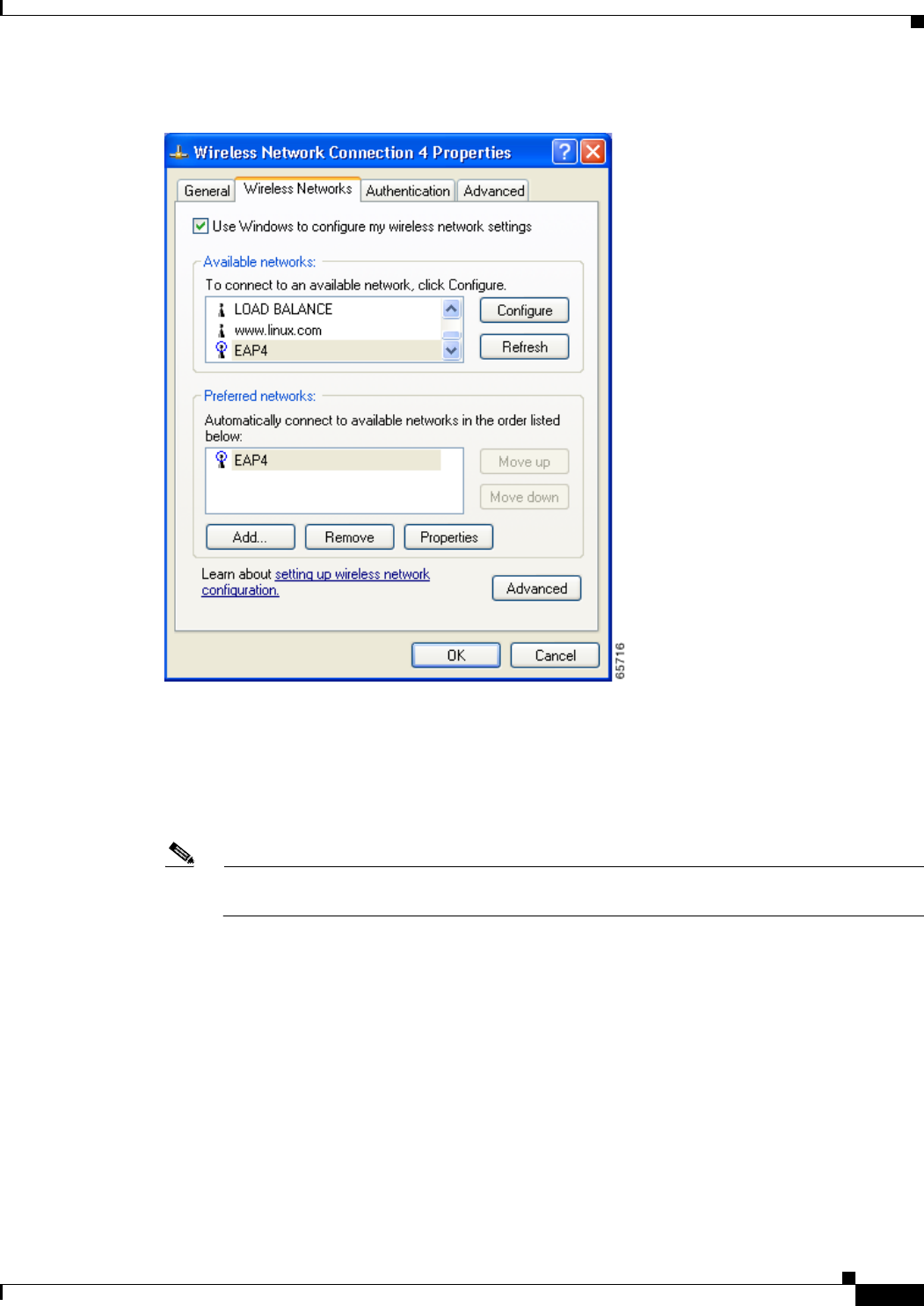
E-5
Cisco Aironet Wireless LAN Client Adapters Installation and Configuration Guide for Windows
OL-1394-06
Appendix E Configuring the Client Adapter through Windows XP Configuring the Client Adapter
Figure E-1 Wireless Network Connection Properties Screen (Wireless Networks Tab)
Step 6 Make sure that the Use Windows to configure my wireless network settings check box is checked.
Step 7 Select the SSID of the access point to which you want the client adapter to associate from the list of
available networks and click Configure. If the SSID of the access point you want to use is not listed or
you are planning to operate the client adapter in an ad hoc network (a computer-to-computer network
without access points), click Add.
Note The Allow Broadcast SSID to Associate option on the access point must be enabled for the SSID
to appear in the list of available networks.
The Wireless Network Properties screen appears (see Figure E-2).
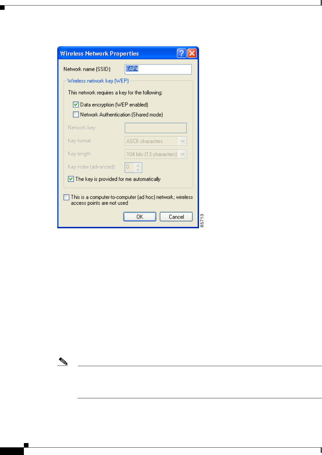
E-6
Cisco Aironet Wireless LAN Client Adapters Installation and Configuration Guide for Windows OL-1394-06
Appendix E Configuring the Client Adapter through Windows XP
Configuring the Client Adapter
Figure E-2 Wireless Network Properties Screen
Step 8 Perform one of the following:
•If you selected an SSID from the list of available networks, make sure the SSID appears in the
Network name (SSID) field.
•If you clicked Add, enter the case-sensitive SSID of the access point or the ad hoc network to which
you want the client adapter to associate in the Network name (SSID) field.
Step 9 Check the Data encryption (WEP enabled) check box if you are planning to use static or dynamic WEP.
Step 10 Check the Network Authentication (Shared mode) check box if you want to use shared key, rather than
open, authentication with the access point.
Open authentication enables your client adapter, regardless of its WEP settings, to authenticate and
attempt to communicate with an access point.
Shared key authentication enables your client adapter to communicate only with access points that have
the same WEP key. Cisco recommends that shared key authentication not be used because it presents a
security risk.
Note If you are planning to use EAP-TLS authentication, do not check this check box. EAP-TLS does
not work with shared key authentication because shared key authentication requires the use of a
WEP key, and a WEP key is not set for EAP-TLS until after the completion of EAP
authentication.

E-7
Cisco Aironet Wireless LAN Client Adapters Installation and Configuration Guide for Windows
OL-1394-06
Appendix E Configuring the Client Adapter through Windows XP Configuring the Client Adapter
Step 11 Follow the steps below to enter up to four WEP keys, if you are planning to use static WEP.
Note If you are planning to use EAP-TLS, PEAP, or EAP-SIM authentication, which uses dynamic
WEP, go to Step 12.
a. Obtain the WEP key for the access point (in an infrastructure network) or other clients (in an ad hoc
network) from your system administrator and enter it in the Network key field. In order to
communicate, the client adapter must use the same WEP key as the access point or other clients.
b. Select one of the following WEP key formats:
–
ASCII characters—Specifies that the WEP key will be entered in ASCII text, which includes
alpha characters, numbers, and punctuation marks.
–
Hexadecimal digits—Specifies that the WEP key will be entered in hexadecimal characters,
which include 0-9, A-F, and a-f.
Note ASCII text WEP keys are not supported on Cisco Aironet 1200 Series Access Points, so you
must select the Hexadecimal digits option if you are planning to use your client adapter with
these access points.
c. Select one of the following WEP key lengths:
–
104 bits (13 characters/26 digits)—You can select this option (or the 40 bits option) if your
client adapter supports 128-bit WEP.
–
40 bits (5 characters/10 digits)—You must select this option if your client adapter supports
only 40-bit WEP.
d. In the Key index (advanced) field, select the number of the WEP key you are creating (0,1,2, or 3).
Note The WEP key must be assigned to the same number on both the client adapter and the access
point (in an infrastructure network) or other clients (in an ad hoc network).
e. Repeat the previous steps if you want to enter another WEP key.
Step 12 Check the The key is provided for me automatically check box if you are planning to use EAP-TLS,
PEAP, or EAP-SIM, which uses dynamic WEP keys.
Step 13 Check the This is a computer-to-computer (ad hoc mode) network; wireless access points are not
used check box if you are planning to operate the client adapter in an ad hoc network.
Step 14 Click OK to save your settings and to add this SSID to the list of preferred networks (see Figure E-1).
The client adapter automatically attempts to associate to the network(s) in the order in which they are
listed.
Step 15 Perform one of the following if you are planning to use EAP authentication:
•If you are planning to use EAP-TLS authentication, follow the instructions in the “Enabling
EAP-TLS Authentication” section below.
•If you are planning to use PEAP authentication, follow the instructions in the “Enabling PEAP
Authentication” section on page E-10.
•If you are planning to use EAP-SIM authentication, follow the instructions in the “Enabling
EAP-SIM Authentication” section on page E-14.
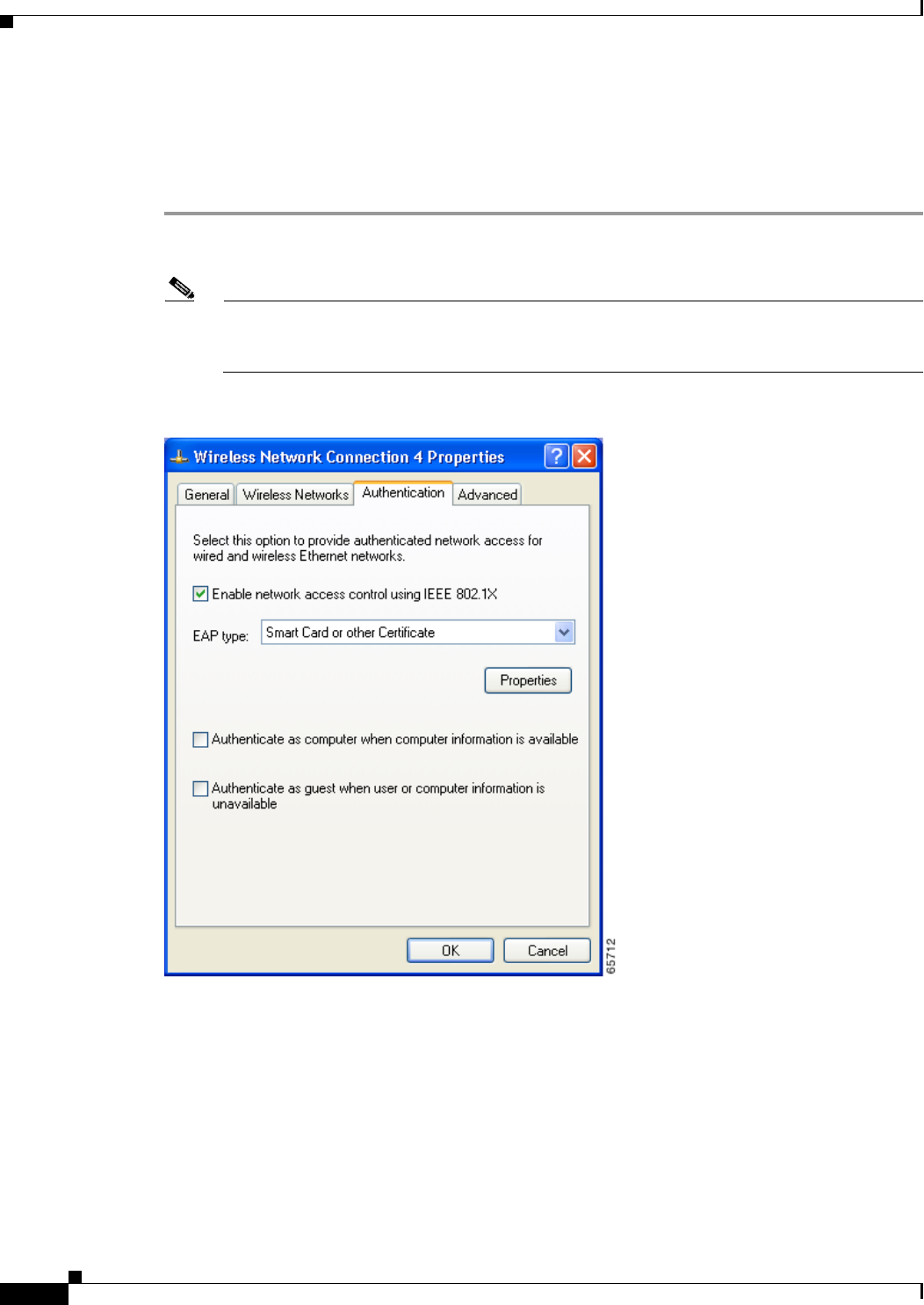
E-8
Cisco Aironet Wireless LAN Client Adapters Installation and Configuration Guide for Windows OL-1394-06
Appendix E Configuring the Client Adapter through Windows XP
Configuring the Client Adapter
Enabling EAP-TLS Authentication
Follow the steps below to prepare the client adapter to use EAP-TLS authentication, provided you have
completed the initial configuration.
Step 1 Click the Authentication tab on the Wireless Network Connection Properties screen. The following
screen appears (see Figure E-3).
Note In Service Pack 1 for Windows XP, the Authentication tab has moved from its previous location.
To access it, click the Wireless Networks tab, select the network that you are configuring in the
Preferred network list, and click Properties.
Figure E-3 Wireless Network Connection Properties Screen (Authentication Tab)
Step 2 Check the Enable network access control using IEEE 802.1X check box.
Step 3 For EAP type, select Smart Card or other Certificate.
Step 4 Click Properties. The Smart Card or other Certificate Properties screen appears (see Figure E-4).
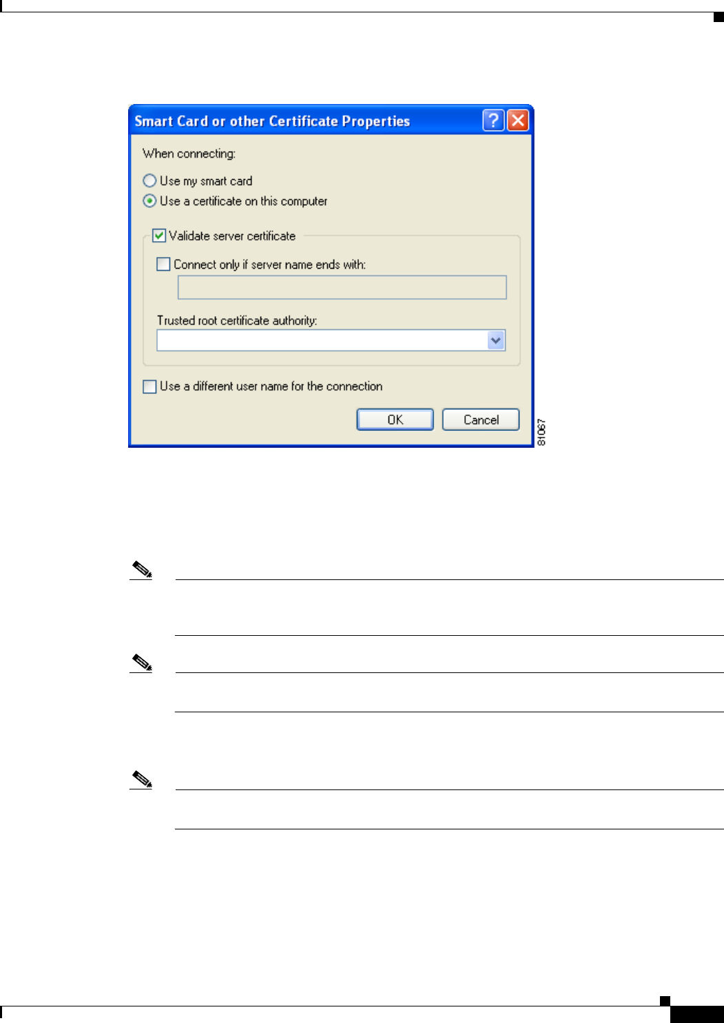
E-9
Cisco Aironet Wireless LAN Client Adapters Installation and Configuration Guide for Windows
OL-1394-06
Appendix E Configuring the Client Adapter through Windows XP Configuring the Client Adapter
Figure E-4 Smart Card or other Certificate Properties Screen
Step 5 Select the Use a certificate on this computer option.
Step 6 Check the Validate server certificate check box if server certificate validation is required.
Step 7 If you want to specify the name of the server to connect to, check the Connect only if server name ends
with check box and enter the appropriate server name suffix in the field below.
Note If you enter a server name and the client adapter connects to a server that does not match the
name you entered, you are prompted to accept or cancel the connection during the authentication
process.
Note If you leave this field blank, the server name is not verified, and a connection is established as
long as the certificate is valid.
Step 8 Make sure that the name of the certificate authority from which the server certificate was downloaded
appears in the Trusted root certificate authority field.
Note If you leave this field blank, you are prompted to accept a connection to the root certification
authority during the authentication process.
Step 9 Click OK twice to save your settings. The configuration is complete.

E-10
Cisco Aironet Wireless LAN Client Adapters Installation and Configuration Guide for Windows OL-1394-06
Appendix E Configuring the Client Adapter through Windows XP
Configuring the Client Adapter
Step 10 If a pop-up message appears above the system tray informing you that you need to accept a certificate
to begin the EAP authentication process, click the message and follow the instructions provided to accept
the certificate.
Note You should not be prompted to accept a certificate for future authentication attempts. After you
accept one, the same certificate is used subsequently.
Step 11 If a message appears indicating the root certification authority for the server’s certificate, and it is the
correct certification authority, click OK to accept the connection. Otherwise, click Cancel.
Step 12 If a message appears indicating the server to which your client adapter is connected, and it is the correct
server to connect to, click OK to accept the connection. Otherwise, click Cancel.
The client adapter should now EAP authenticate.
Note Whenever the computer reboots and you enter your Windows username and password, the EAP
authentication process begins automatically and the client adapter should EAP authenticate.
Step 13 To verify authentication, double-click My Computer,Control Panel, and Network Connections. The
status appears to the right of your Wireless Network Connection. Click View and Refresh to obtain the
current status. If the client adapter is authenticated, the status reads Authentication succeeded.
Enabling PEAP Authentication
Follow the steps below to prepare the client adapter to use PEAP authentication, provided you have
completed the initial configuration.
Step 1 Click the Authentication tab on the Wireless Network Connection Properties screen. The following
screen appears (see Figure E-5).
Note In Service Pack 1 for Windows XP, the Authentication tab has moved from its previous location.
To access it, click the Wireless Networks tab, select the network that you are configuring in the
Preferred network list, and click Properties.
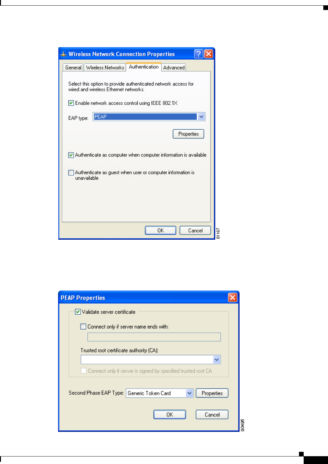
E-11
Cisco Aironet Wireless LAN Client Adapters Installation and Configuration Guide for Windows
OL-1394-06
Appendix E Configuring the Client Adapter through Windows XP Configuring the Client Adapter
Figure E-5 Wireless Network Connection Properties Screen (Authentication Tab)
Step 2 Check the Enable network access control using IEEE 802.1X check box.
Step 3 For EAP type, select PEAP. Click Properties. The PEAP Properties screen appears (see Figure E-6).
Figure E-6 PEAP Properties Screen
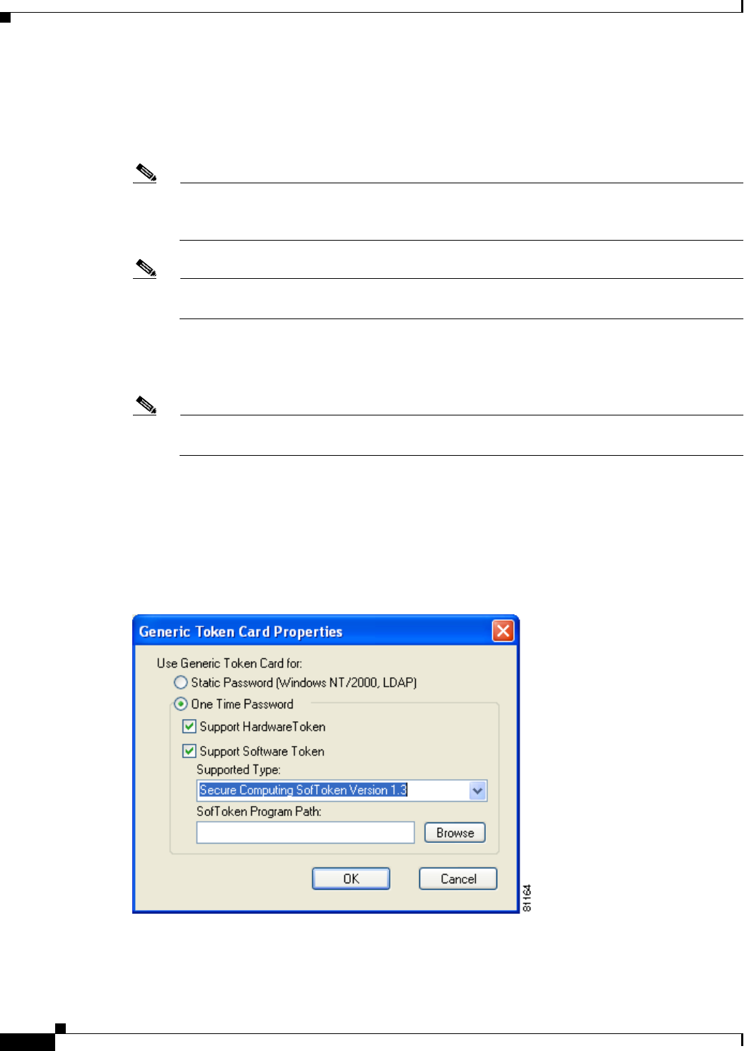
E-12
Cisco Aironet Wireless LAN Client Adapters Installation and Configuration Guide for Windows OL-1394-06
Appendix E Configuring the Client Adapter through Windows XP
Configuring the Client Adapter
Step 4 Check the Validate server certificate check box if server certificate validation is required
(recommended).
Step 5 If you want to specify the name of the server to connect to, check the Connect only if server name ends
with check box and enter the appropriate server name suffix in the field below.
Note If you enter a server name and the client adapter connects to a server that does not match the
name you entered, you are prompted to accept or cancel the connection during the authentication
process.
Note If you leave this field blank, the server name is not verified, and a connection is established as
long as the certificate is valid.
Step 6 Make sure that the name of the certificate authority from which the server certificate was downloaded
appears in the Trusted root certificate authority (CA) field. If necessary, click the arrow on the
drop-down menu and select the appropriate name.
Note If you leave this field blank, you are prompted to accept a connection to the root certification
authority during the authentication process.
Step 7 Check the Connect only if server is signed by specified trusted root CA check box if you want to
ensure that the certificate server uses the trusted root certificate specified in the field above. This
prevents the client from establishing connections to rogue access points.
Step 8 Currently Generic Token Card is the only second phase EAP type available. Click Properties. The
Generic Token Card Properties screen appears (see Figure E-7).
Figure E-7 Generic Token Card Properties Screen

E-13
Cisco Aironet Wireless LAN Client Adapters Installation and Configuration Guide for Windows
OL-1394-06
Appendix E Configuring the Client Adapter through Windows XP Configuring the Client Adapter
Step 9 Select either the Static Password (Windows NT/2000, LDAP) or the One Time Password option,
depending on your user database.
Step 10 Perform one of the following:
•If you selected the Static Password (Windows NT/2000, LDAP) option in Step 9, go to Step 11.
•If you selected the One Time Password option in Step 9, check one or both of the following check
boxes to specify the type of tokens that will be supported for one-time passwords:
–
Support Hardware Token—A hardware token device obtains the one-time password. You
must use your hardware token device to obtain the one-time password and enter the password
when prompted for your user credentials.
–
Support Software Token—The PEAP supplicant works with a software token program to
retrieve the one-time password. You have to enter only the PIN, not the one-time password. If
you check this check box, you must also select from the Supported Type drop-down box the
software token software that is installed on the client (such as Secure Computing SofToken
Version 1.3, Secure Computing SofToken II 2.0, or RSA SecurID Software Token v 2.5), and if
Secure Computing SofToken Version 1.3 is selected, you must find the software program path
using the Browse button.
Note The SofToken Program Path field is unavailable if a software token program other than
Secure Computing SofToken Version 1.3 is selected.
Step 11 Click OK three times to save your settings. The configuration is complete.
Step 12 Refer to the “Using PEAP” section on page 6-16 for instructions on authenticating using PEAP.
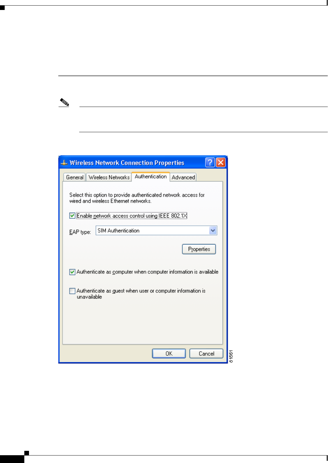
E-14
Cisco Aironet Wireless LAN Client Adapters Installation and Configuration Guide for Windows OL-1394-06
Appendix E Configuring the Client Adapter through Windows XP
Configuring the Client Adapter
Enabling EAP-SIM Authentication
Follow the steps below to prepare the client adapter to use EAP-SIM authentication, provided you have
completed the initial configuration.
Step 1 Click the Authentication tab on the Wireless Network Connection Properties screen. The following
screen appears (see Figure E-8).
Note In Service Pack 1 for Windows XP, the Authentication tab has moved from its previous location.
To access it, click the Wireless Networks tab, select the network that you are configuring in the
Preferred network list, and click Properties.
Figure E-8 Wireless Network Connection Properties Screen (Authentication Tab)
Step 2 Check the Enable network access control using IEEE 802.1X check box.
Step 3 For EAP type, select SIM Authentication.
Step 4 Click Properties. The SIM Authentication Properties screen appears (see Figure E-9).
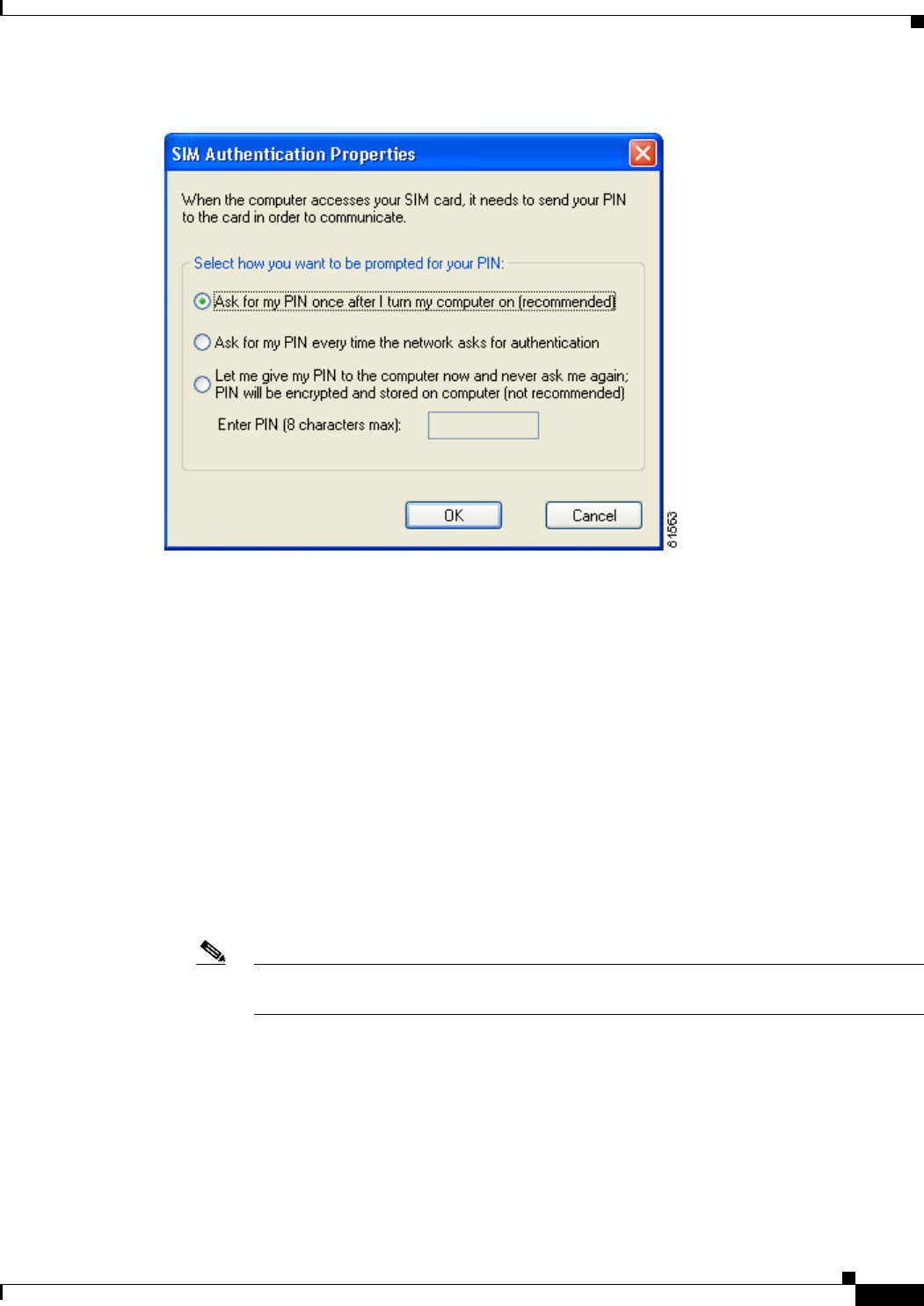
E-15
Cisco Aironet Wireless LAN Client Adapters Installation and Configuration Guide for Windows
OL-1394-06
Appendix E Configuring the Client Adapter through Windows XP Configuring the Client Adapter
Figure E-9 SIM Authentication Properties Screen
Step 5 To access any resources (data or commands) on the SIM, the EAP-SIM supplicant must provide a valid
PIN to the SIM card, which must match the PIN stored on the SIM. Select one of the following options
to specify how the EAP-SIM supplicant should handle the SIM card’s PIN:
•Ask for my PIN once after I turn my computer on (recommended)—The software does not
permanently store the PIN. It prompts you for the PIN once, on the first authentication of every
session, where a session is defined as the time between power-up and shutdown or reboot.
•Ask for my PIN every time the network asks for authentication—The software never stores the
PIN; it prompts you for the PIN every time an EAP-SIM authentication is performed. This option is
not recommended if your client will be roaming between access points or if session timeouts are
implemented (such as for accounting and security purposes).
•Let me give my PIN to the computer now and never ask me again; PIN will be encrypted and
stored on computer (not recommended)—You need to enter the PIN only once, in the Enter PIN
edit box below this option. The software stores the PIN in the registry and retrieves it from there
when required. If you select this option, you must enter the PIN now. The PIN is validated when an
authentication attempt is made.
Note This option is not recommended because it enables others to use the SIM without knowing
the PIN.

E-16
Cisco Aironet Wireless LAN Client Adapters Installation and Configuration Guide for Windows OL-1394-06
Appendix E Configuring the Client Adapter through Windows XP
Associating to an Access Point Using Windows XP
Step 6 Click OK twice to save your settings. The configuration is complete.
If you chose to store the PIN in the computer’s registry, the EAP authentication process begins
automatically, and the client adapter should EAP authenticate and use the saved PIN to access the SIM
card.
Note If the stored PIN is wrong and therefore rejected by the SIM, the EAP-SIM supplicant
temporarily changes the prompt mode to the default setting (Ask for my PIN once after I turn
my computer on) in order to prevent the SIM from locking up. Unless changed manually, this
setting stays in effect until your computer is powered off. Change your stored PIN on the SIM
Authentication Properties screen.
If you chose to be prompted for the PIN after a power-up or reboot or at every authentication request, a
pop-up message appears above the Windows system tray informing you that you need to enter your
credentials to access the network. Click the message, enter your PIN, and click OK. The client adapter
should now EAP authenticate.
Step 7 To verify authentication, double-click My Computer,Control Panel, and Network Connections. The
status appears to the right of your Wireless Network Connection. Click View and Refresh to obtain the
current status. If the client adapter is authenticated, the status reads Authentication succeeded.
Note ACU and the Windows Wireless Network Connection icon in the Windows XP system tray may
indicate a connection status when authentication is still in the pending state or the authentication
server fails to respond.
Associating to an Access Point Using Windows XP
Windows XP causes the client adapter’s driver to automatically attempt to associate to the first network
in the list of preferred networks (see Figure E-1). If the adapter fails to associate or loses association, it
automatically switches to the next network in the list of preferred networks.The adapter does not switch
networks as long as it remains associated to the access point. To force the client adapter to associate to
a different access point, you must select a different network from the list of available networks (and click
Configure and OK).
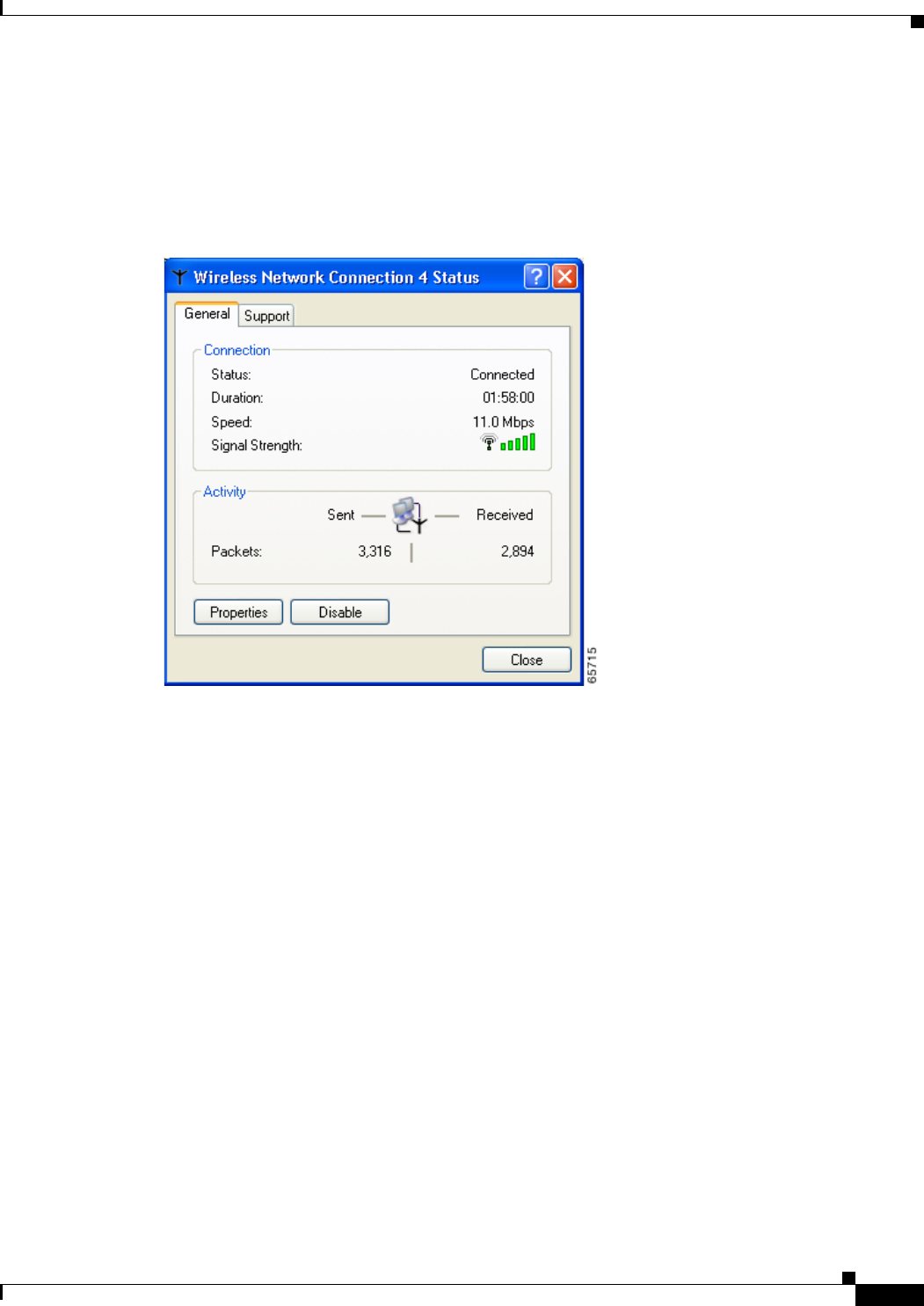
E-17
Cisco Aironet Wireless LAN Client Adapters Installation and Configuration Guide for Windows
OL-1394-06
Appendix E Configuring the Client Adapter through Windows XP Viewing the Current Status of Your Client Adapter
Viewing the Current Status of Your Client Adapter
To view the status of your client adapter, click the icon of the two connected computers in the Windows
system tray. The Wireless Network Connection Status screen appears (see Figure E-10).
Figure E-10 Wireless Network Connection Status Screen

E-18
Cisco Aironet Wireless LAN Client Adapters Installation and Configuration Guide for Windows OL-1394-06
Appendix E Configuring the Client Adapter through Windows XP
Viewing the Current Status of Your Client Adapter

F-1
Cisco Aironet Wireless LAN Client Adapters Installation and Configuration Guide for Windows
OL-1394-06
APPENDIX
F
Performing a Site Survey
This appendix explains how ACU’s site survey tool can be used when conducting a site survey.
The following topics are covered in this appendix:
•Overview, page F-2
•Specifying Signal Strength Units, page F-3
•Using Passive Mode, page F-3
•Using Active Mode, page F-7
•Forcing the Client Adapter to Reassociate, page F-13

F-2
Cisco Aironet Wireless LAN Client Adapters Installation and Configuration Guide for Windows OL-1394-06
Appendix F Performing a Site Survey
Overview
Overview
Note This appendix applies only to people who are responsible for conducting a site survey to determine the
best placement of infrastructure devices within a wireless network.
ACU’s site survey tool can assist you in conducting a site survey. The tool operates at the RF level and
is used to determine the best placement and coverage (overlap) for your network’s infrastructure devices.
During a site survey, the current status of the network is read from the client adapter and displayed four
times per second so you can accurately gauge network performance. The feedback that you receive can
help you to eliminate areas of low RF signal levels that can result in a loss of connection between the
client adapter and its associated access point (or other infrastructure device).
The site survey tool can be operated in two modes:
•Passive Mode—This is the default site survey mode. It does not initiate any RF network traffic; it
simply listens to the traffic that the client adapter hears and displays the results. Follow the
instructions in the “Using Passive Mode” section on page F-3 to activate the passive mode.
•Active Mode—This mode causes the client adapter to actively send or receive low-level RF packets
to or from its associated access point and provides information on the success rate. It also enables
you to set parameters governing how the site survey is performed (such as the data rate). Follow the
instructions in the “Using Active Mode” section on page F-7 to activate the active mode.
Guidelines
Keep the following guidelines in mind when preparing to perform a site survey:
•Perform the site survey when the RF link is functioning with all other systems and noise sources
operational.
•Execute the site survey entirely from the mobile station.
•When using the active mode, conduct the site survey with all variables set to operational values.
Additional Information
Also consider the following operating and environmental conditions when performing a site survey:
•Data rates—Sensitivity and range are inversely proportional to data bit rates. Therefore, the
maximum radio range is achieved at the lowest workable data rate, and a decrease in receiver
threshold sensitivity occurs as the radio data increases.
•Antenna type and placement—Proper antenna configuration is a critical factor in maximizing
radio range. As a general rule, range increases in proportion to antenna height.
•Physical environment—Clear or open areas provide better radio range than closed or filled areas.
Also, the less cluttered the work environment, the greater the range.

F-3
Cisco Aironet Wireless LAN Client Adapters Installation and Configuration Guide for Windows
OL-1394-06
Appendix F Performing a Site Survey Specifying Signal Strength Units
•Obstructions—A physical obstruction such as metal shelving or a steel pillar can hinder the
performance of wireless devices. Avoid placing these devices in a location where a metal barrier is
between the sending and receiving antennas.
•Building materials—Radio penetration is greatly influenced by the building material used in
construction. For example, drywall construction allows greater range than concrete blocks, and
metal or steel construction is a barrier to radio signals.
Note Refer to the documentation for your infrastructure device for additional information on factors affecting
placement.
Specifying Signal Strength Units
Follow the steps below to specify how signal strength units are displayed on the site survey screens.
Step 1 Open ACU.
Step 2 Click the Preferences icon or select Preferences from the Options drop-down menu. The Aironet Client
Utility Preferences screen appears.
Step 3 Under Signal Strength Display Units, select one of the following options:
•Percent—Displays the signal strength as a percentage.
•dBm—Displays the signal strength in decibels with respect to milliwatts.
Step 4 Click OK to save your changes.
Using Passive Mode
Step 1 Open ACU; then click the Site Survey icon or select Site Survey from the Commands drop-down menu.
The Site Survey - Passive Mode screen appears, provided a client adapter is installed in your computer
and is running.
Figure F-1 shows the Site Survey - Passive Mode screen with the signal strength values displayed as
percentages, and Figure F-2 shows the top of the same screen with the signal strength values displayed
in dBm.
Note The name of the current profile appears in parentheses at the top of the screen.
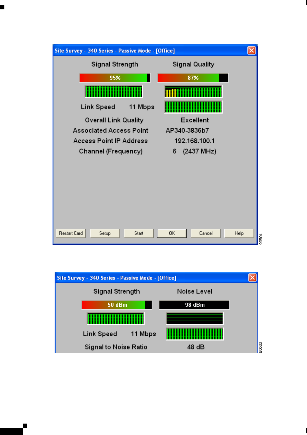
F-4
Cisco Aironet Wireless LAN Client Adapters Installation and Configuration Guide for Windows OL-1394-06
Appendix F Performing a Site Survey
Using Passive Mode
Figure F-1 Site Survey - Passive Mode Screen (with Signal Strength as a Percentage)
Figure F-2 Top of Site Survey - Passive Mode Screen (with Signal Strength in dBm)

F-5
Cisco Aironet Wireless LAN Client Adapters Installation and Configuration Guide for Windows
OL-1394-06
Appendix F Performing a Site Survey Using Passive Mode
Table F-1 interprets the information that is displayed on the Site Survey - Passive Mode screen.
Table F-1 Site Survey Passive Mode Statistics
Statistic Description
Signal Strength The signal strength for all received packets. The higher the value
and the more green the bar graph is, the stronger the signal.
The histogram below the bar graph provides a visual
interpretation of the current signal strength. Differences in signal
strength are indicated by the following colors: green (strongest),
yellow (middle of the range), and red (weakest).
Range: 0 to 100% or –95 to –45 dBm
Signal Quality
(2.4-GHz client adapters) The signal quality for all received packets. The higher the value
and the more green the bar graph is, the clearer the signal.
The histogram below the bar graph provides a visual
interpretation of the current signal quality. Differences in signal
quality are indicated by the following colors: green (highest
quality), yellow (average), and red (lowest quality).
Range: 0 to 100%
Note This setting appears only for 2.4-GHz client adapters and
only if you selected signal strength to be displayed as a
percentage. See the “Specifying Signal Strength Units”
section on page F-3 for information.
Noise Level
(2.4-GHz client adapters) The level of background radio frequency energy in the 2.4-GHz
band. The lower the value and the more green the bar graph is, the
less background noise present.
The histogram below the bar graph provides a visual
interpretation of the current level of background noise.
Differences in background noise level are indicated by the
following colors: green (low noise), yellow (middle of the range),
and red (high noise).
Range: –100 to –45 dBm
Note This setting appears only for 2.4-GHz client adapters and
only if you selected signal strength to be displayed in
dBm. See the “Specifying Signal Strength Units” section
on page F-3 for information.
Beacons Received
(5-GHz client adapters) The percentage of beacon packets received versus those expected
to be received. The higher the value and the more green the bar
graph is, the clearer the signal.
Example: The access point sends out 10 beacons per second, so
you would expect the client adapter to receive 50
beacon packets in 5 seconds. If it receives only 40
packets, the percentage of beacons received would be
80%.
Range: 0 to 100%
Note This setting appears only for 5-GHz client adapters.

F-6
Cisco Aironet Wireless LAN Client Adapters Installation and Configuration Guide for Windows OL-1394-06
Appendix F Performing a Site Survey
Using Passive Mode
Link Speed In passive mode, the site survey tool monitors transmitted
network traffic, and the data rate reflects the rate at which the
packets are being transmitted.
The Link Speed histogram provides a visual interpretation of the
current rate at which your client adapter is transmitting packets.
Differences in link speed are indicated by the following colors:
green (fastest), yellow (middle of the range), and red (slowest).
Value: 1, 2, 5.5, or 11 Mbps (2.4-GHz client adapters);
6, 9, 12, 18, 24, 36, 48, or 54 Mbps (5-GHz client
adapters)
Overall Link Quality The client adapter’s ability to communicate with the access point.
Value: Not Associated, Poor, Fair, Good, or Excellent
Note This setting appears for 2.4-GHz client adapters (but only
if you selected signal strength to be displayed as a
percentage) and for 5-GHz client adapters. See the
“Specifying Signal Strength Units” section on page F-3
for information.
Signal to Noise Ratio
(2.4-GHz client adapters) The difference between the signal strength and the noise level.
The higher the value, the better the client adapter’s ability to
communicate with the access point.
Range: 0 to 90 dB
Note This setting appears only for 2.4-GHz client adapters and
only if you selected signal strength to be displayed in
dBm. See the “Specifying Signal Strength Units” section
on page F-3 for information.
Associated Access Point The access point to which your client adapter is associated. It is
shown only if the client adapter is in infrastructure mode, the
access point was configured with a name, and Aironet Extensions
are enabled (on access points running Cisco IOS release
12.2(4)JA or greater).
Access Point IP Address The IP address of the access point to which your client adapter is
associated. It is shown only if the client adapter is in
infrastructure mode, the access point was configured with an IP
address, and Aironet Extensions are enabled (on access points
running Cisco IOS release 12.2(4)JA or greater).
Note If Aironet Extensions are disabled, the IP address of the
associated access point is shown as 0.0.0.0.
Table F-1 Site Survey Passive Mode Statistics (continued)
Statistic Description
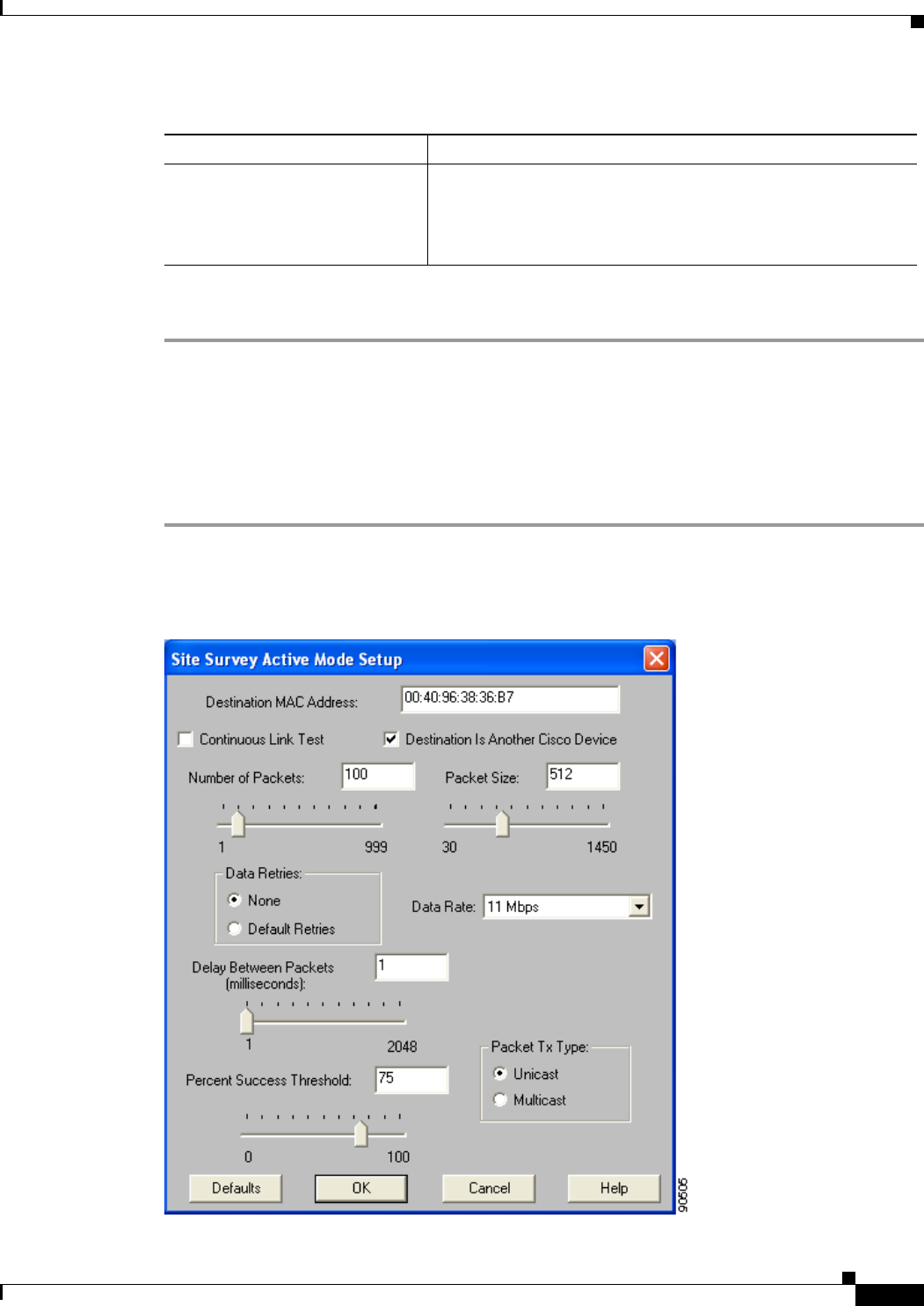
F-7
Cisco Aironet Wireless LAN Client Adapters Installation and Configuration Guide for Windows
OL-1394-06
Appendix F Performing a Site Survey Using Active Mode
Step 2 If you want to activate the site survey active mode, go to the “Using Active Mode” section on page F-7.
Otherwise, click OK or Cancel to exit the site survey application.
Using Active Mode
Follow the steps below to activate the site survey active mode and obtain current information about your
client adapter’s ability to transmit and receive RF packets.
Step 1 From the Site Survey - Passive Mode screen (see Figure F-1), click the Setup button. The Site Survey
Active Mode Setup screen appears (see Figure F-3).
Figure F-3 Site Survey Active Mode Setup Screen
Channel (Frequency) The frequency that your client adapter is currently using as the
channel for communications.
Value: Dependent on client adapter radio and regulatory
domain
Table F-1 Site Survey Passive Mode Statistics (continued)
Statistic Description

F-8
Cisco Aironet Wireless LAN Client Adapters Installation and Configuration Guide for Windows OL-1394-06
Appendix F Performing a Site Survey
Using Active Mode
Table F-2 lists and describes the parameters that affect how the site survey is performed. Follow the
instructions in the table to set any parameters.
Table F-2 Site Survey Active Mode Parameters
Parameter Description
Destination MAC Address The MAC address of the access point (in infrastructure mode) or other
clients (in ad hoc mode) that are used in the test.
Default: The MAC address of the access point (in infrastructure mode)
to which your client adapter is associated
Note During the test, the client adapter does not roam to other access
points so that the size of a single cell can be determined.
Continuous Link Test Checking this check box causes the test to run until you click OK or
Stop. The test loops repeatedly for the number of packets specified in
the Number of Packets field.
Default: Unchecked
Destination Is Another
Cisco/Aironet Device Checking this check box indicates that the device you named in the
Destination MAC Address field is a Cisco Aironet access point (in
infrastructure mode) or client (in ad hoc mode). In this case, packets sent
to the client from the Cisco Aironet device contain additional information,
such as lost to source, lost to target, and percent retries, and this
information is displayed in the Site Survey - Active screen.
If the device specified in the Destination MAC Address field is not a
Cisco Aironet device, do not check this check box. In this case, the test
sends out loopback packets, which originate from and return to the
client adapter.
Default: Checked
Number of Packets The number of packets that are sent during the test.
Range: 1 to 999
Default: 100
Packet Size The size of the packets that are sent during the test. Select a size that is
typical during normal system use.
Range: 30 to 1450
Default: 512
Data Retries The number of times a transmission is retried if an acknowledgment
(Ack) is not returned by the destination device.
Default: None
Retry Value Description
None No retries will occur.
Default Retries The firmware’s default value for retries
(16 for 2.4-GHz client adapters; 32 for
5-GHz client adapters) will be used.

F-9
Cisco Aironet Wireless LAN Client Adapters Installation and Configuration Guide for Windows
OL-1394-06
Appendix F Performing a Site Survey Using Active Mode
Step 2 After setting any parameters, click OK to save the settings. The Site Survey - Passive Mode screen
appears (see Figure F-1).
Step 3 Click the Start button to run the site survey test. The Site Survey - Active Mode screen appears.
Figure F-4 shows the Site Survey - Active Mode screen with the signal strength values displayed as
percentages, and Figure F-5 shows the top of the same screen with the signal strength values displayed
in dBm.
Data Rate The bit rate at which packets are transmitted. Rate shifting does not
occur during the test because the echo test built into the radio firmware
does not support it.
Value: 1, 2, 5.5, or 11 Mbps (2.4-GHz client adapters);
6, 9, 12, 18, 24, 36, 48, or 54 Mbps (5-GHz client adapters)
Default: 11 Mbps (2.4-GHz client adapters);
54 Mbps (5-GHz client adapters)
Delay Between Packets The delay (in milliseconds) between successive transmissions.
Range: 1 to 2048 ms
Default: 50 ms
Percent Success Threshold The percentage of packets that are not lost.
This parameter controls the red line on the Percent Successful
histogram. Percentages greater than or equal to this value are displayed
as green bars; percentages below this value are displayed as yellow
bars.
Range: 0 to 100%
Default: 75
Packet Tx Type The packet type that is transmitted during the test.
Default: Unicast
Packet Type Description
Unicast When unicast packets are used, the system
expects to receive an acknowledgment
from the destination, and retries can occur.
Multicast When multicast packets are used, no
packet retries occur during the test.
Table F-2 Site Survey Active Mode Parameters (continued)
Parameter Description
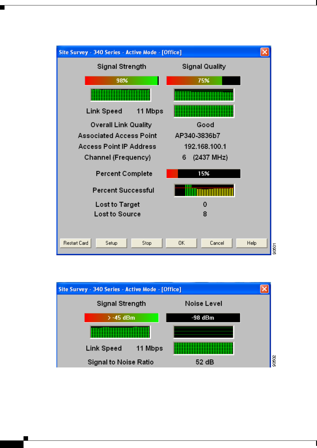
F-10
Cisco Aironet Wireless LAN Client Adapters Installation and Configuration Guide for Windows OL-1394-06
Appendix F Performing a Site Survey
Using Active Mode
Figure F-4 Site Survey - Active Mode Screen (with Signal Strength as a Percentage)
Figure F-5 Top of Site Survey - Active Mode Screen (with Signal Strength in dBm)

F-11
Cisco Aironet Wireless LAN Client Adapters Installation and Configuration Guide for Windows
OL-1394-06
Appendix F Performing a Site Survey Using Active Mode
Table F-3 interprets the information that is displayed on the Site Survey - Active Mode screen while the
site survey test is running.
Table F-3 Site Survey Active Mode Statistics
Statistic Description
Signal Strength The signal strength for all received packets. The higher the value
and the more green the bar graph is, the stronger the signal.
The histogram below the bar graph provides a visual
interpretation of the current signal strength. Differences in signal
strength are indicated by the following colors: green (strongest),
yellow (middle of the range), and red (weakest).
Range: 0 to 100% or –95 to –45 dBm
Signal Quality
(2.4-GHz client adapters) The signal quality for all received packets. The higher the value
and the more green the bar graph is, the clearer the signal.
The histogram below the bar graph provides a visual
interpretation of the current signal quality. Differences in signal
quality are indicated by the following colors: green (highest
quality), yellow (average), and red (lowest quality).
Range: 0 to 100%
Note This setting appears only for 2.4-GHz client adapters and
only if you selected signal strength to be displayed as a
percentage. See the “Specifying Signal Strength Units”
section on page F-3 for information.
Noise Level
(2.4-GHz client adapters) The level of background radio frequency energy in the 2.4-GHz
band. The lower the value and the more green the bar graph is, the
less background noise present.
The histogram below the bar graph provides a visual
interpretation of the current level of background noise.
Differences in background noise level are indicated by the
following colors: green (low noise), yellow (middle of the range),
and red (high noise).
Range: –100 to –45 dBm
Note This setting appears only for 2.4-GHz client adapters and
only if you selected signal strength to be displayed in
dBm. See the “Specifying Signal Strength Units” section
on page F-3 for information.
Beacons Received
(5-GHz client adapters) The percentage of beacon packets received versus those expected
to be received. The higher the value and the more green the bar
graph is, the clearer the signal.
Example: The access point sends out 10 beacons per second, so
you would expect the client adapter to receive 50
beacon packets in 5 seconds. If it receives only 40
packets, the percentage of beacons received would be
80%.
Range: 0 to 100%
Note This setting appears only for 5-GHz client adapters.

F-12
Cisco Aironet Wireless LAN Client Adapters Installation and Configuration Guide for Windows OL-1394-06
Appendix F Performing a Site Survey
Using Active Mode
Link Speed The rate at which your client adapter is transmitting packets to or
from its associated access point.
The Link Speed histogram provides a visual interpretation of the
current rate at which your client adapter is transmitting packets.
Differences in link speed are indicated by the following colors:
green (fastest), yellow (middle of the range), and red (slowest).
Value: 1, 2, 5.5, or 11 Mbps (2.4-GHz client adapters);
6, 9, 12, 18, 24, 36, 48, or 54 Mbps (5-GHz client
adapters)
Overall Link Quality The client adapter’s ability to communicate with the access point.
Value: Not Associated, Poor, Fair, Good, or Excellent
Note This setting appears for 2.4-GHz client adapters (but only
if you selected signal strength to be displayed as a
percentage) and for 5-GHz client adapters. See the
“Specifying Signal Strength Units” section on page F-3
for information.
Signal to Noise Ratio
(2.4-GHz client adapters) The difference between the signal strength and the noise level.
The higher the value, the better the client adapter’s ability to
communicate with the access point.
Range: 0 to 90 dB
Note This setting appears only for 2.4-GHz client adapters and
only if you selected signal strength to be displayed in
dBm. See the “Specifying Signal Strength Units” section
on page F-3 for information.
Associated Access Point The access point to which your client adapter is associated. It is
shown only if the client adapter is in infrastructure mode, the
access point was configured with a name, and Aironet Extensions
are enabled (on access points running Cisco IOS release
12.2(4)JA or greater).
Access Point IP Address The IP address of the access point to which your client adapter is
associated. It is shown only if the client adapter is in
infrastructure mode, the access point was configured with an IP
address, and Aironet Extensions are enabled (on access points
running Cisco IOS release 12.2(4)JA or greater).
Note If Aironet Extensions are disabled, the IP address of the
associated access point is shown as 0.0.0.0.
Channel (Frequency) The frequency that your client adapter is currently using as the
channel for communications.
Value: Dependent on client adapter radio and regulatory
domain
Percent Complete The percentage of packets that have been transmitted based on the
number specified in the Number of Packets field.
Table F-3 Site Survey Active Mode Statistics (continued)
Statistic Description

F-13
Cisco Aironet Wireless LAN Client Adapters Installation and Configuration Guide for Windows
OL-1394-06
Appendix F Performing a Site Survey Forcing the Client Adapter to Reassociate
Step 4 When you click the Stop button or when the Percent Complete reaches 100%, the active mode changes
back to the passive mode.
Step 5 Click OK or Cancel to exit the site survey application.
Forcing the Client Adapter to Reassociate
The client adapter will attempt to maintain its association to an access point for as long as it can.
Therefore if you are on a fringe area while conducting a site survey, you may want to reinitialize (or
restart) the client adapter in an attempt to force it to disassociate from the access point to which it is
currently associated and reassociate to another access point.
Note Restarting the client adapter may cause you to lose your wireless network connection.
Follow the steps below to attempt to force the client adapter to disassociate from its current access point
and reassociate to another during a site survey.
Step 1 Click the Restart Card button on the bottom of the Site Survey screen.
Step 2 When prompted to confirm your decision, click Yes. The driver stops the client adapter’s radio, writes
the configuration (although no parameter settings have been changed), and restarts the radio.
Percent Successful The percentage of packets that were transmitted successfully.
The Percent Successful histogram provides a visual interpretation
of the percentage of packets that are not lost. The value you set
for the Percent Success Threshold is indicated by the red line.
Percentages greater than or equal to this value are displayed as
green bars; percentages below this value are displayed as yellow
bars.
Note Refer to the Percent Success Threshold parameter in
Table F-2 for more information.
Lost to Target The number of packets that were not transmitted successfully to
the access point.
Lost to Source The number of packets that were not received successfully from
the access point.
Table F-3 Site Survey Active Mode Statistics (continued)
Statistic Description

F-14
Cisco Aironet Wireless LAN Client Adapters Installation and Configuration Guide for Windows OL-1394-06
Appendix F Performing a Site Survey
Forcing the Client Adapter to Reassociate

GL-1
Cisco Aironet Wireless LAN Client Adapters Installation and Configuration Guide for Windows
OL-1394-06
GLOSSARY
802.1X Also called 802.1X for 802.11. 802.1X is the new standard for wireless LAN security, as defined by the
Institute of Electrical and Electronics Engineers (IEEE). An access point that supports 802.1X and its
protocol, Extensible Authentication Protocol (EAP), acts as the interface between a wireless client and an
authentication server, such as a Remote Authentication Dial-In User Service (RADIUS) server, to which the
access point communicates over the wired network.
802.11 The IEEE standard that specifies carrier sense media access control and physical layer specifications
for 1- and 2-megabit-per-second (Mbps) 2.4-GHz wireless LANs.
802.11a The IEEE standard that governs the deployment of 5-GHz OFDM systems. It specifies the
implementation of the physical layer for wireless UNII bands (see UNII,UNII 1, and UNII 2) and
provides four channels per 100 MHz of bandwidth.
802.11b The IEEE standard that specifies carrier sense media access control and physical layer specifications
for 5.5- and 11-Mbps 2.4-GHz wireless LANs.
A
access point A wireless LAN data transceiver that uses radio waves to connect a wired network with wireless
stations.
ad hoc network A wireless network composed of stations without access points.
alphanumeric A set of characters that contains both letters and numbers.
associated A station is configured properly to allow it to wirelessly communicate with an access point.
B
bandwidth Specifies the amount of the frequency spectrum that is usable for data transfer. It identifies the
maximum data rate that a signal can attain on the medium without encountering significant power loss.
BPSK Binary phase shift keying. A modulation technique used by IEEE 802.11-compliant wireless LANs for
transmission at 1 Mbps.
broadcast key
rotation A security feature for use with dynamic WEP keys. If your client adapter uses LEAP, EAP-TLS, PEAP,
or EAP-SIM authentication and you enable this feature, the access point changes the dynamic broadcast
WEP key that it provides at the interval you select.

Glossary
GL-2
Cisco Aironet Wireless LAN Client Adapters Installation and Configuration Guide for Windows OL-1394-06
C
CCK Complementary code keying. A modulation technique used by IEEE 802.11b-compliant wireless LANs
for transmission at 5.5 and 11 Mbps.
client A radio device that uses the services of an access point to communicate wirelessly with other devices
on a local area network.
CSMA Carrier sense multiple access. A wireless LAN media access method specified by the IEEE 802.11
specification.
cyclic redundancy
check (CRC) A method of checking for errors in a received packet.
D
data rates The range of data transmission rates supported by a device. Data rates are measured in megabits per
second (Mbps).
dBi A ratio of decibels to an isotropic antenna that is commonly used to measure antenna gain. The greater
the dBi value, the higher the gain and the more acute the angle of coverage.
DHCP Dynamic Host Configuration Protocol. A protocol available with many operating systems that
automatically issues IP addresses within a specified range to devices on the network. The device retains
the assigned address for a specific administrator-defined period.
dipole A type of low-gain (2.2-dBi) antenna consisting of two (often internal) elements.
DSSS Direct-sequence spread spectrum. A type of spread spectrum radio transmission that spreads its signal
continuously over a wide frequency band.
duplicate packets Packets that were received twice because an acknowledgement got lost and the sender retransmitted the
packet.
E
EAP Extensible Authentication Protocol. EAP is the protocol for the optional IEEE 802.1X wireless LAN
security feature. An access point that supports 802.1X and EAP acts as the interface between a wireless
client and an authentication server, such as a Remote Authentication Dial-In User Service (RADIUS) server,
to which the access point communicates over the wired network.
Ethernet The most widely used wired local area network. Ethernet uses carrier sense multiple access (CSMA)
to allow computers to share a network and operates at 10, 100, or 1000 megabits per second (Mbps),
depending on the physical layer used.

Glossary
GL-3
Cisco Aironet Wireless LAN Client Adapters Installation and Configuration Guide for Windows
OL-1394-06
.
F
file server A repository for files so that a local area network can share files, mail, and programs.
firmware Software that is programmed on a memory chip and kept in a computer’s semi-permanent memory.
fragmentation
threshold The size at which packets are fragmented and transmitted a piece at a time instead of all at once. The
setting must be within the range of 64 to 2312 bytes.
full duplex A means of communication whereby each node receives and transmits simultaneously (two-way). See
also half duplex.
G
gateway A device that connects two otherwise incompatible networks together.
GHz Gigahertz. One billion cycles per second. A unit of measure for frequency.
H
half duplex A means of communication whereby each node receives and transmits in turn (one-way). See also full
duplex.
hexadecimal A set of characters consisting of ten numbers and six letters (0-9, A-F, and a-f).
I
IEEE Institute of Electrical and Electronics Engineers. A professional society serving electrical engineers
through its publications, conferences, and standards development activities. The body responsible for
the Ethernet 802.3 and wireless LAN 802.11 specifications.
infrastructure The wired Ethernet network.
infrastructure
device A device (such as an access point, bridge, or base station) that connects client adapters to a wired LAN.
IP address The Internet Protocol (IP) address of a station.
IP subnet mask The number used to identify the IP subnetwork, indicating whether the IP address can be recognized
on the LAN or if it must be reached through a gateway.
IPX Internetwork Packet Exchange. The NetWare network layer protocol used for transferring data from
servers to workstations.
isotropic An antenna that emits its signal in a spherical pattern.

Glossary
GL-4
Cisco Aironet Wireless LAN Client Adapters Installation and Configuration Guide for Windows OL-1394-06
L
LEAP LEAP, or EAP-Cisco Wireless, is the 802.1X authentication type that is available for use with operating
systems that do not have EAP support. Support for LEAP is provided in the client adapter’s firmware
and the Cisco software that supports it, rather than in the operating system. With LEAP, a username and
password are used by the client adapter to perform mutual authentication with the RADIUS server
through an access point.
M
MAC address The Media Access Control (MAC) address is a unique serial number assigned to a networking device
by the manufacturer.
MIC Message integrity check. MIC prevents bit-flip attacks on encrypted packets. During a bit-flip attack,
an intruder intercepts an encrypted message, alters it slightly, and retransmits it, and the receiver
accepts the retransmitted message as legitimate. The client adapter’s driver must support MIC
functionality, and MIC must be enabled on the access point.
modulation Any of several techniques for combining user information with a transmitter’s carrier signal.
multicast packets Packets transmitted to multiple stations.
multipath The echoes created as a radio signal bounces off of physical objects.
O
OFDM Orthogonal frequency division multiplexing. A multicarrier modulation method for broadband wireless
communications.
overrun packets Packets that were discarded because the access point had a temporary overload of packets to handle.
P
packet A basic message unit for communication across a network. A packet usually includes routing
information, data, and sometimes error detection information.
Q
QPSK Quadruple phase shift keying. A modulation technique used by IEEE 802.11-compliant wireless LANs
for transmission at 2 Mbps.

Glossary
GL-5
Cisco Aironet Wireless LAN Client Adapters Installation and Configuration Guide for Windows
OL-1394-06
R
radio channel The frequency at which a radio operates.
range A linear measure of the distance that a transmitter can send a signal.
receiver sensitivity A measurement of the weakest signal a receiver can receive and still correctly translate it into data.
RF Radio frequency. A generic term for radio-based technology.
roaming A feature of some access points that allows users to move through a facility while maintaining an
unbroken connection to the LAN.
RP-TNC A connector type unique to Cisco Aironet radios and antennas. Part 15.203 of the FCC rules covering
spread spectrum devices limits the types of antennas that may be used with transmission equipment. In
compliance with this rule, Cisco Aironet, like all other wireless LAN providers, equips its radios and
antennas with a unique connector to prevent attachment of non-approved antennas to radios.
RTS threshold The packet size at which an access point issues a request to send (RTS) before sending the packet.
S
spread spectrum A radio transmission technology that spreads the user information over a much wider bandwidth than
otherwise required in order to gain benefits such as improved interference tolerance and unlicensed
operation.
SSID Service set identifier. A unique identifier that stations must use to be able to communicate with an
access point. The SSID can be any alphanumeric entry up to a maximum of 32 characters.
T
TKIP Temporal Key Integrity Protocol. Also referred to as WEP key hashing. A security feature that defends
against an attack on WEP in which the intruder uses the initialization vector (IV) in encrypted packets
to calculate the WEP key. TKIP removes the predictability that an intruder relies on to determine the
WEP key by exploiting IVs.
transmit power The power level of radio transmission.
U
unicast packets Packets transmitted in point-to-point communication.
UNII Unlicensed National Information Infrastructure. An FCC regulatory domain for 5-GHz wireless
devices. UNII bands are 100 MHz wide and divided into four channels when using 802.11a OFDM
modulation.

Glossary
GL-6
Cisco Aironet Wireless LAN Client Adapters Installation and Configuration Guide for Windows OL-1394-06
UNII 1 A UNII band dedicated to in-building wireless LAN applications. UNII 1 is located at 5.15 to 5.25 GHz
and allows for a maximum transmit power of 40 mW (or 16 dBm) with an antenna up to 6 dBi. UNII 1
regulations require a nonremovable, integrated antenna.
UNII 2 A UNII band dedicated to in-building wireless LAN applications. UNII 2 is located at 5.25 to 5.35 GHz
and allows for a maximum transmit power of 200 mW (or 23 dBm) with an antenna up to 6 dBi. UNII
2 regulations allow for an auxiliary, user-installable antenna.
W
WEP Wired equivalent privacy. An optional security mechanism defined within the 802.11 standard designed
to protect your data as it is transmitted through your wireless network by encrypting it through the use
of encryption keys.
workstation A computing device with an installed client adapter.

IN-1
Cisco Aironet Wireless LAN Client Adapters Installation and Configuration Guide for Windows
OL-1394-06
INDEX
Numerics
802.1X
authentication types
in ACU 5-22 to 5-24
in Windows XP E-3
defined 5-22, E-2
A
About Aironet Client Utility
ACU menu option 9-13
screen 9-13
About icon 9-13
access point
currently associated to 7-9, 8-11
in wireless infrastructure 1-10
IP address
current 7-9, 8-11
in link test 7-19
in site survey active mode F-12
in site survey passive mode F-6
MAC address
current 7-10
in link test 7-21
in site survey active mode F-8
specifying 5-16
mismatches 7-13
name
current 7-9, 8-11
in link test 7-21
in site survey active mode F-12
in site survey passive mode F-6
problems
associating to 10-11
authenticating to 10-11
role in wireless network 1-8
security settings 5-27 to 5-28
Access Point Authentication parameter 5-29
access points, reporting those that fail LEAP
authentication 5-26, 5-28
Ack packets
number received 7-15
number transmitted 7-15
ACM
See Aironet Client Monitor (ACM)
ACU
See Aironet Client Utility (ACU)
ad hoc network
defined E-5
parameters 5-17 to 5-20
selecting in ACU 5-6
selecting in Windows XP E-7
wireless LAN configuration 1-9
Advanced (Ad Hoc) screen 5-17
Advanced (Infrastructure) screen 5-14
advanced ad hoc parameters
described 5-2, 5-17
setting 5-17 to 5-20
advanced infrastructure parameters
described 5-2, 5-14
setting 5-14 to 5-16
aged packets 7-14, 7-16
Aironet Client Monitor (ACM)
About screen 8-5
accessing help 8-5

Index
IN-2
Cisco Aironet Wireless LAN Client Adapters Installation and Configuration Guide for Windows OL-1394-06
described 1-6
exiting 8-6
finding version 8-5
icon 8-2
overview 8-2
pop-up menu 8-5 to 8-11
selecting the active profile 8-8 to 8-9
setting preferences 8-6 to 8-7
specifying pop-up menu options 8-7
specifying when it runs 8-7
Tool Tip window 8-3 to 8-4
using 8-1 to 8-11
Aironet Client Monitor parameter (Install Wizard) 3-7,
3-17
Aironet Client Monitor Preferences screen 8-6
Aironet Client Utility (ACU)
About icon 9-13
accessing help 9-14
described 1-6 to 1-8
diagnostic tools
overview 7-2
setting parameters 7-3 to 7-4
using 7-4 to 7-22
exiting 9-13
feature comparison to Windows XP 3-22 to 3-23
finding version 9-13
icon
adding to desktop 9-14
deleting from desktop 9-14
parameter to place on desktop 3-7, 3-17
using to open ACU 9-12
installation program settings, modifying 9-13
launching from ACM 8-6
opening 9-12
overview 1-6 to 1-7
Properties screens, overview 5-2
screens, buttons described 1-8
selecting among several installed client adapters 3-24
Aironet Client Utility parameter (Install Wizard) 3-6, 3-16
Aironet Client Utility Preferences screen 4-10, 7-3, 9-11
Aironet Client Utility screen 1-6 to 1-7
Allow Association to Mixed Cells parameter 5-21
Allow Non-Administrator Users to Save Profiles to the
Registry parameter 4-11
Allow Non-Administrator Users to Save Settings to the
Registry parameter (Install Wizard) 3-7, 3-17
Allow Saved LEAP User Name and Password parameter
(Install Wizard) 3-9, 3-19
antenna
2.4-GHz options C-3
described 1-4
gains
IEEE 802.11a D-4
IEEE 802.11b D-4 to D-5
mode currently being used 7-8
placement F-2
specifications A-5
Antenna Mode (Receive) parameter
ad hoc mode 5-18
infrastructure mode 5-15
Antenna Mode (Transmit) parameter
ad hoc mode 5-18
infrastructure mode 5-15
Apply button, function 1-8
association
rejections 7-14
time-outs 7-14
audience of document xii
authentication
process 5-24, E-4
rejections 7-13
time-outs 7-14
type, status of 7-7
Automatically Load New Firmware When NDIS Driver Is
Updated parameter 9-11
Automatically Prompt for LEAP User Name and Password
option 5-33

Index
IN-3
Cisco Aironet Wireless LAN Client Adapters Installation and Configuration Guide for Windows
OL-1394-06
auto profile selection
including a profile in 4-4 to 4-6
prioritizing profiles 4-6
removing a profile from 4-5
restrictions 4-5
using 4-7, 8-8
Auto Profile Selection Management screen 4-5
Auto Start parameter for ACM (Install Wizard) 3-7, 3-17
B
beacon packets
number received 7-12
number transmitted 7-15
beacon period, status of 7-10
Beacon Period parameter 5-20
beacons received
current 7-11, 7-22
in site survey active mode F-11
in site survey passive mode F-5
boot block firmware, current version of 7-6
broadcast key rotation
described 5-25
setting on client and access point 5-28
broadcast packets
number received 7-12
number transmitted 7-15
broadcast SSIDs 5-4, E-5
bytes
number received 7-12
number transmitted 7-15
C
CAM
See Constantly Awake Mode (CAM)
Canadian compliance statement C-3 to C-4
Cancel button, function 1-8
Card and Socket Services 2-4
carrier/correlation (Car/Cor) 5-12
caution, defined xiii
Certificate Properties screen - Windows 98, 98 SE, NT,
and Me 5-37
Change Password screen 6-18
Change PIN screen 6-19
channel
current 7-9
determining if clear 5-12
in site survey active mode F-12
in site survey passive mode F-7
Channel parameter 5-10
channels, supported by regulatory domains
IEEE 802.11a D-2
IEEE 802.11b D-3
channel set, for which client adapter is configured 7-8
Cisco Aironet Wireless LAN Adapter Setup screen (Install
Wizard) 3-20
Cisco Aironet Wireless LAN Client Adapter Installation
Wizard screen 3-3, 3-13, 9-7
Cisco Wireless LAN Adapter Troubleshooting
screen 10-4, 10-5
Clear Channel Assessment parameter 5-12
client name 7-8
Client Name parameter 5-4
client utilities
See Aironet Client Utility (ACU) and Aironet Client
Monitor (ACM)
clock, setting to display seconds 1-7
collisions, multiple/single 7-15
Commands drop-down menu 6-11, 6-12, 9-13
configuring client adapter
deciding between ACU and Windows XP 3-22 to 3-23
in ACU 5-1 to 5-43
in Windows XP E-4 to E-16
Connection Status screen (ACM) 8-9
Constantly Awake Mode (CAM) 5-5
Contents ACU menu option 9-14

Index
IN-4
Cisco Aironet Wireless LAN Client Adapters Installation and Configuration Guide for Windows OL-1394-06
Continuous Link Test parameter
in RF link test 7-19
in site survey active mode F-8
conventions of document xiii to xiv
CRC error
in packet 7-13
in PLCP header 7-13
CTS packets
number received 7-15
number transmitted 7-15
Custom Installation screen (Install Wizard) 3-4, 3-14
D
data rate
for which client adapter is configured 7-8
mismatches 7-13
specifications A-4
when performing a site survey F-2
Data Rate parameter
in RF network 5-8
in site survey active mode F-9
Data Retries parameter
in RF network 5-13
in site survey active mode F-8
dBm
signal strength units in site survey F-3
signal strength units on Status and Linktest screens 7-4
declarations of conformity
European community, Switzerland, Norway, Iceland,
and Liechtenstein C-4 to C-6
FCC C-2 to C-3
RF exposure C-6
Defaults button, function 1-8
default values, displaying 1-8
Delay Between Packets parameter F-9
Destination Is Another Cisco/Aironet Device
parameter F-8
Destination MAC Address parameter F-8
diagnosing client adapter operation 10-4 to 10-6
dipole antenna 1-4, B-3
Disable Firmware Checking parameter (Install
Wizard) 3-6, 3-16
Display Seconds on Clock parameter 1-7
diversity antenna 1-4
diversity mode 5-15, 5-18
document
audience xii
conventions xiii to xiv
organization xii to xiii
purpose xii
software versions covered xii
domain name
including in Windows login 5-33
specifying for saved user name and password 5-33
driver
current version 7-6
described 1-5
finding version 9-7
Drivers parameter (Install Wizard) 3-6, 3-16
duplicate packets, number received 7-12
dynamic WEP keys, overview 5-22 to 5-24, E-2 to E-4
E
EAP authentication
described E-4
overview 5-22 to 5-25, 6-2, E-2 to E-4
using 6-1 to 6-21
EAP-Cisco Wireless
See LEAP authentication
EAP-SIM authentication
authenticating if the PIN is stored on the computer 6-21
authenticating if you are prompted for the PIN 6-20
described 5-24 to 5-25, E-3, E-4
disabling 5-42 to 5-43

Index
IN-5
Cisco Aironet Wireless LAN Client Adapters Installation and Configuration Guide for Windows
OL-1394-06
enabling
in Windows XP E-14 to E-16
through ACU 5-34 to 5-42
error messages 10-26 to 10-31
RADIUS servers supported 5-24, E-3
setting on client and access point 5-28
EAP-SIM parameter (Install Wizard) 3-9, 3-19
EAP-TLS authentication
authenticating after a reboot/logon 6-15
authenticating after profile selection/card
insertion 6-15
described 5-23 to 5-25, E-3, E-4
disabling 5-42 to 5-43
enabling
in Windows XP E-8 to E-10
through ACU 5-34 to 5-38
RADIUS servers supported 5-23, E-3
setting on client and access point 5-27
EIRP, maximum 1-4, D-4 to D-5
energy detect (ED) 5-12
Enter PIN screen 6-20
error messages 10-13 to 10-31
errors
MAC CRC 7-13
overrun 7-13
PLCP 7-13
F
Fast PSP 5-5
fast secure roaming
described 5-26
setting on client and access point 5-28
FCC
declaration of conformity statement C-2 to C-3
safety compliance statement 2-2
firmware
current version 7-6
finding version 9-8
preventing from being installed with driver 9-10 to 9-12
upgrading 9-8 to 9-10
Firmware parameter (Install Wizard) 3-6, 3-16
forcing client adapter to reassociate F-13
fragmented packets 5-13
Fragment Threshold parameter 5-13
frequencies D-2, D-3
frequency
currently being used 7-9
in site survey active mode F-12
in site survey passive mode F-7
setting 5-10
G
Generic Token Card Properties screen 5-40, E-12
H
hardware components of client adapter 1-3 to 1-4
Help
button, function 1-8
drop-down menu 9-14
icon 9-14
history of RF performance, displayed 7-4
host-based EAP authentication
described 5-23 to 5-25
disabling 5-42 to 5-43
enabling 5-34 to 5-42
requirements 5-34
Host Based EAP option 5-35
host devices 2-4
I
I/O range 10-8
Include Windows Logon Domain with User Name
parameter 5-33
infrastructure device, defined 1-3

Index
IN-6
Cisco Aironet Wireless LAN Client Adapters Installation and Configuration Guide for Windows OL-1394-06
infrastructure network
parameters 5-14 to 5-16
selecting in ACU 5-6
wireless LAN configuration 1-10
inserting client adapter 9-2 to 9-4
Installable Drivers screen (Install Wizard) 3-14
Installation Path parameter
for ACM (Install Wizard) 3-7, 3-17
for ACU (Install Wizard) 3-6, 3-16
installing client adapter software
on Windows 98, 98 SE, 2000, Me, or XP 3-2 to 3-11
on Windows NT 3-12 to 3-22
Install Wizard file
described 1-5
finding version 9-5
installing 3-2 to 3-22
name 3-2
interference 2-6
interrupt request (IRQ) 10-8
introduction to client adapters 1-2 to 1-3
IP address
of access point in link test 7-19
of access point in site survey active mode F-12
of access point in site survey passive mode F-6
of associated access point 7-9, 8-11
of client adapter 7-8, 8-4, 8-11
J
Japan, guidelines for operating client adapters C-6 to C-7
L
LEAP authentication
authenticating after a reboot/logon
with automatically prompted login 6-7 to 6-8
with manually prompted login 6-11 to 6-13
with saved username and password 6-14
with Windows username and password 6-4 to 6-5
authenticating after profile selection/card insertion
with automatically prompted login 6-6
with manually prompted login 6-9 to 6-11
with saved username and password 6-13
with Windows username and password 6-3 to 6-4
authenticating after your LEAP credentials expire
with automatically prompted login 6-9
with manually prompted login 6-13
with saved username and password 6-14
with Windows username and password 6-5
described 5-22 to 5-23, 5-24
disabling 5-42
enabling 5-31 to 5-34
error messages 10-18 to 10-21
overview 6-2 to 6-3
RADIUS servers supported 5-22
requirements 5-31
setting on client and access point 5-27
stages of 6-3
LEAP Authentication Status screen
displayed 6-2
minimizing 6-3
LEAP Authentication Timeout Value parameter 5-33
LEAP login screen
appearing before Windows login screen 10-13
displayed 6-6, 6-7, 6-10, 6-12
LEAP option 5-31
LEAP parameter (Install Wizard) 3-9, 3-19
LEAP security module 5-23, 5-31
LEAP Settings screen 5-32
LEDs
described 1-4
interpreting 10-2 to 10-3
using to verify installation 3-22
link quality
in link test 7-22
in site survey active mode F-12

Index
IN-7
Cisco Aironet Wireless LAN Client Adapters Installation and Configuration Guide for Windows
OL-1394-06
in site survey passive mode F-6
overall 7-11, 8-4, 8-10
link speed
currently being used 7-8, 8-4, 8-11
in link test 7-21
in site survey active mode F-12
in site survey passive mode F-6
Link Status Meter
ACU menu option 7-16
icon 7-16
screen 7-16
viewing 7-16 to 7-17
Linktest
ACU menu option 7-18
screen 7-18, 7-20
statistics 7-21
Link Test icon 7-18
LM card
antenna 1-4, 5-15, 5-18
described 1-2
Load Firmware icon 1-5, 9-9
Load New Firmware
ACU menu option 1-5, 9-9
screen 9-9
long radio headers, using 5-9
M
MAC address
of access point, specifying 5-16
of access point in link test 7-21
of access point in site survey active mode F-8
of associated access point 7-10
of client adapter 7-8
MAC CRC errors 7-13
Manual LEAP Login ACU menu option 6-10, 6-11
Manually Prompt for LEAP User Name and Password
option 5-33
Max Power Savings
See Max PSP
Max PSP 5-5
Menu Options (Defaults) parameter for ACM (Install
Wizard) 3-8, 3-18
message integrity check (MIC)
described 5-25, 7-7
setting on client and access point 5-28
statistics 7-14
status of 7-7
microcellular network 1-10
Microsoft 802.1X supplicant 5-34
Microsoft hot fix
described 10-13
uninstalling 9-16
Microsoft TCP/IP Properties screen (Install Wizard) 3-21
mini PCI card
antenna 1-4, 5-15, 5-18
described 1-2
losing association upon resuming from suspend
mode 10-12
multicast packets
in site survey active mode F-9
number received 7-12
number transmitted 7-15
N
network
configurations 1-8 to 1-10
prioritizing connections 10-11 to 10-12
problems connecting to 10-11
security parameters
described 5-2, 5-20
setting 5-20 to 5-43
type, current 7-9
network login screen 6-8
Network Security screen 5-20
Network Security Type parameter 5-29, 5-31, 5-35, 5-42

Index
IN-8
Cisco Aironet Wireless LAN Client Adapters Installation and Configuration Guide for Windows OL-1394-06
Network Type parameter 5-6
noise level
current 7-10
in link test 7-22
in site survey active mode F-11
in site survey passive mode F-5
No Network Connection Unless User Is Logged In
parameter 5-33
note, defined xiii
Number of Packets parameter
in link test 7-19
in site survey active mode F-8
O
OK button, function 1-8
One Time Password screen 6-17
online help
for ACM 8-5
for ACU 9-14
for troubleshooting utility 10-7
open authentication 5-29, E-6
Options drop-down menu 1-7, 4-10, 7-3, 9-10, F-3
organization of document xii to xiii
overrun errors 7-13
P
package contents 2-3
packets
Ack 7-15
aged 7-14, 7-16
beacon 5-20, 7-10, 7-12, 7-15
broadcast 7-12, 7-15
CTS 7-15
duplicate 7-12
fragmented 5-13
linktest statistics 7-21
multicast 7-12, 7-15, F-9
RTS 5-16, 5-19, 7-15
site survey active mode statistics F-11 to F-13
site survey passive mode statistics F-5 to F-7
statistics 7-12 to 7-16
unicast 7-12, 7-15
with MIC 7-14
Packet Size parameter 7-19, F-8
Packet Tx Type parameter F-9
PC card
antenna 1-4, 5-15, 5-18
described 1-2
inserting 9-2 to 9-3
removing 9-4
PC-Cardbus card
antenna 1-4
described 1-2
inserting 9-2 to 9-3
profiles tied to slot 4-3
removing 9-4
PCI card
antenna 1-4, 5-15, 5-18
described 1-2
inserting 9-3 to 9-4
removing 9-5
PEAP authentication
authenticating after profile selection/card
insertion/reboot/logon 6-16 to 6-18
authenticating after your password expires (Windows
NT or 2000 domain databases) 6-18
authenticating after your PIN expires (OTP
databases) 6-19
described 5-23 to 5-25, E-3, E-4
disabling 5-42 to 5-43
enabling
in Windows XP E-10 to E-13
through ACU 5-34 to 5-41
error messages 10-21 to 10-26
RADIUS servers supported 5-23, E-3
setting on client and access point 5-27
PEAP parameter (Install Wizard) 3-10, 3-19

Index
IN-9
Cisco Aironet Wireless LAN Client Adapters Installation and Configuration Guide for Windows
OL-1394-06
PEAP Properties screen 5-39, E-11
peer-to-peer network 1-9, 5-6
percent
signal strength units in site survey F-3
signal strength units on Status and Linktest screens 7-4
Percent Successful histogram, in site survey active
mode F-9, F-13
Percent Success Threshold parameter F-9
physical specifications A-2
Place Icon on Desktop parameter (Install Wizard) 3-7,
3-17
PLCP
CRC errors 7-13
format errors 7-13
length errors 7-13
power level
current 7-8
maximum D-4 to D-5
power levels, available 7-9
power save mode, currently being used 7-9
Power Save Mode parameter 5-5
power specifications A-6
Preferences
ACU menu option 1-7, 4-10, 7-3, 9-10, F-3
icon 1-7, 4-10, 7-3, 9-10, F-3
product model numbers 1-3
profile
active 8-3, 8-10
current 7-6
default 7-6
displayed in ACU title bar 1-7
Profile Manager
ACU menu option 4-2
icon 4-2
screen
displayed 4-2
parameters missing 4-3, 10-12
profile manager
auto profile selection feature 4-4 to 4-6
creating a new profile 4-3
deleting a profile 4-8
editing a profile 4-7
exporting a profile 4-9
granting or denying access to non-administrative
users 4-10 to 4-11
importing a profile 4-9
opening 4-2 to 4-3
overview 4-2
parameters missing 4-3, 10-12
renaming a profile 4-8
selecting the active profile 4-6 to 4-7
setting a profile to default values 4-8
Profiles Submenu (ACM) 8-8
Program Feature Overrides parameter for ACM (Install
Wizard) 3-8, 3-18
Program Folder parameter
for ACM (Install Wizard) 3-7, 3-17
for ACU (Install Wizard) 3-6, 3-16
Protected EAP
See PEAP authentication
purpose of document xii
R
radio
described 1-3
specifications A-3 to A-5
turning on or off 8-7, 9-15 to 9-16
RADIUS servers
additional information 5-25, E-4
defined 5-22, E-2
supported 5-22 to 5-24, E-3
range 5-8, 5-11
Reauthenticate
ACM menu option 8-8
ACU menu option 6-21

Index
IN-10
Cisco Aironet Wireless LAN Client Adapters Installation and Configuration Guide for Windows OL-1394-06
reauthentication process 6-21
receive statistics 7-12 to 7-14
regulatory
domains 5-10, 7-8
IEEE 802.11a D-2
IEEE 802.11b D-3
information C-2 to C-7
specifications A-6 to A-7
related publications xv
removing client adapter 9-4 to 9-5
Reset button 7-12, 7-14
resource conflicts, resolving
in Windows 2000 10-9 to 10-10
in Windows 98, 98 SE, and Me 10-8
in Windows NT 10-9
in Windows XP 10-10
Restart Card
ACU menu option 9-15
button, in site survey F-13
restarting client adapter 9-15, F-13
RF link test
prerequisites 7-18
running 7-17 to 7-22
stopping 7-22
RF network parameters
described 5-2, 5-7
setting 5-7 to 5-13
RF Network screen 5-7
RF obstructions 2-6, F-3
roaming 1-10
RTS packets
advanced ad hoc parameters 5-19
advanced infrastructure parameters 5-16
number retransmitted 7-15
number transmitted 7-15
RTS Retry Limit parameter
ad hoc mode 5-19
infrastructure mode 5-16
RTS Threshold parameter
ad hoc mode 5-19
infrastructure mode 5-16
S
safety
information 2-2 to 2-3
specifications A-6 to A-7
saved username and password
described 5-32
entering 5-33
Screen Update Timer parameter 7-4
seamless roaming 1-10
security features
overview 5-21 to 5-25
synchronizing 5-27 to 5-28
Select A Wireless LAN Adapter Card screen 3-24
Select Profile
ACM menu option 8-8 to 8-9
ACU menu option 4-4
icon 4-4
screen 4-4
sensitivity A-4, F-2
serial number of client adapter 7-6
server-based authentication, status of 7-7
Setup button, in site survey F-7
shared key authentication 5-29, E-6
short radio headers
status of 7-6
using 5-9
Show History parameter 7-4
signal quality
current 7-10
in link test 7-21
in site survey active mode F-11
in site survey passive mode F-5
on Link Status Meter screen 7-17

Index
IN-11
Cisco Aironet Wireless LAN Client Adapters Installation and Configuration Guide for Windows
OL-1394-06
signal strength
as a percentage 7-4, F-3
current 7-10
in dBm 7-4, F-3
in link test 7-21
in site survey active mode F-11
in site survey passive mode F-5
on Link Status Meter screen 7-17
Signal Strength Display Units parameter 7-4
signal to noise ratio
current 7-11
in link test 7-22
in site survey active mode F-12
in site survey passive mode F-6
SIM Authentication Properties screen 5-41, E-15
site requirements
for client devices 2-6
for infrastructure devices 2-5
Site Survey
Active Mode screen F-10
Active Mode Setup screen F-7
ACU menu option F-3
icon F-3
Passive Mode screen F-4
site survey
active mode
overview F-2
setting parameters F-8 to F-9
starting F-9
statistics F-11 to F-13
using F-7 to F-13
exiting F-7, F-13
guidelines F-2
passive mode
overview F-2
statistics F-5 to F-7
using F-3 to F-7
specifying signal strength units F-3
Smart Card or other Certificate Properties screen 5-37, E-9
software
installing on Windows 98, 98 SE, 2000, Me, or
XP 3-2 to 3-11
installing on Windows NT 3-12 to 3-22
procedures 9-5 to 9-15
uninstalling 9-6 to 9-7
verifying installation 3-22
software components
custom installation parameters 3-6 to 3-10, 3-16 to 3-19
described 1-5 to 1-8
software versions covered in document xii
specifications
physical A-2
power A-6
radio A-3 to A-5
regulatory compliance A-6 to A-7
safety A-6 to A-7
Specified Access Point 1- 4 parameters 5-16
spread spectrum 1-3
SSID
current 7-9, 8-3, 8-11
mismatches 7-13
SSID1 parameter 5-4
SSID2 parameter 5-4
SSID3 parameter 5-4
Start After Install parameter for ACM (Install
Wizard) 3-7, 3-17
Start button
function 1-8
in RF link test 7-19
in site survey F-9
Static Password screen 6-16
static WEP
disabling 5-31
procedures 5-29 to 5-31
with open authentication, setting on client and access
point 5-27
with shared key authentication, setting on client and
access point 5-27

Index
IN-12
Cisco Aironet Wireless LAN Client Adapters Installation and Configuration Guide for Windows OL-1394-06
static WEP keys
entering 5-29 to 5-30
guidelines for entering
in ACU 5-30
in Windows XP E-7
overview 5-22, E-2
overwriting 5-30
selecting transmit key 5-30
size of 5-29
Statistics
ACU menu option 7-11
icon 7-11
screen 7-12
statistics
client adapter, viewing 7-11 to 7-16
link test 7-21
receive 7-12 to 7-14
site survey
active mode F-11 to F-13
passive mode F-5 to F-7
transmit 7-15 to 7-16
Status
ACU menu option 7-4, 9-7, 9-8
icon 7-4, 9-7, 9-8
screen 7-5
status of client adapter
in ACM Connection Status screen 8-9 to 8-11
in ACM Tool Tip window 8-4
in ACU status bar 1-7
in ACU Status screen 7-4 to 7-11
in link test 7-21
in Windows XP E-17
Stop button
function 1-8
in site survey active mode F-13
system parameters
described 5-2, 5-3
setting 5-3 to 5-6
System Parameters screen 5-3
system requirements 2-4 to 2-5
T
Temporal Key Integrity Protocol (TKIP)
described 5-25
setting on client and access point 5-28
temporary username and password
automatically prompt for 5-33
described 5-32
manually prompt for 5-33
selecting options 5-33
using Windows credentials 5-33
throughput 5-5, 5-8, 5-9, 5-13
transmit key 5-30
Transmit Power parameter 5-11
transmit statistics 7-15 to 7-16
Troubleshooting ACU menu option 10-4
troubleshooting information, accessing 10-2
troubleshooting utility
accessing help 10-7
activating from ACM 8-6
saving detailed report to text file 10-6 to 10-7
using 10-4 to 10-7
Turn Radio Off
ACM menu option 8-8
ACU menu option 9-16
Turn Radio On
ACM menu option 8-8
ACU menu option 9-16
U
unicast packets
in site survey active mode F-9
number received 7-12
number transmitted 7-15

Index
IN-13
Cisco Aironet Wireless LAN Client Adapters Installation and Configuration Guide for Windows
OL-1394-06
uninstalling client adapter software 9-6 to 9-7
unpacking the client adapter 2-3
Unplug or Eject Hardware icon (Windows) 9-4
upgrading client adapter software
on Windows 98, 98 SE, 2000, Me, or XP 3-2 to 3-11
on Windows NT 3-12 to 3-22
upgrading firmware 9-8 to 9-10
up time
statistic 7-14
status of 7-10
Use Another Application to Configure My Wireless
Settings option 4-7
Use Auto Profile Selection option 4-7, 8-8
Use Other Configuration Application (ACM) 8-8
Use Saved User Name and Password option 5-32
Use Selected Profile option 4-6
Use Short Radio Headers parameter 5-9
Use Temporary User Name and Password option 5-32
Use Windows to configure my wireless network settings
parameter - Windows XP E-5
Use Windows User Name and Password option 5-33
W
Wake Duration parameter 5-19
warning
defined xiii to xiv
dipole antenna 2-3, B-3
explosive device proximity 2-3, B-2
laptop users 2-3, B-4 to B-5
WEP
designation in product model numbers 1-3
keys
additional security features 5-25
defined 5-21, E-2
size of 5-22, E-2
types of 5-21, E-2
parameter 5-29
status of 7-7
WEP Key Entry Method parameter 5-29
WEP key hashing 5-25
Windows login screen 6-4
Windows Wireless Network Connection icon, shows
unavailable connection 10-12
Windows XP
configuring client adapter through E-4 to E-16
enabling EAP-SIM authentication E-14 to E-16
enabling EAP-TLS authentication E-8 to E-10
enabling PEAP authentication E-10 to E-13
feature comparison to ACU 3-22 to 3-23
inability to use fast user switching 3-9
making a configuration decision 3-22 to 3-23
security features E-2 to E-4
viewing status of client adapter E-17
wireless infrastructure 1-10
Wireless Network Connection Properties screen
(Authentication Tab) - Windows 5-36, E-8, E-11,
E-14
Wireless Network Connection Properties screen (Wireless
Networks Tab) - Windows E-5
Wireless Network Connection Status screen - Windows
XP E-17
Wireless Network Properties screen - Windows XP E-6
workstation
defined 1-3
in wireless infrastructure 1-10
World Mode parameter 5-9

Index
IN-14
Cisco Aironet Wireless LAN Client Adapters Installation and Configuration Guide for Windows OL-1394-06