Xsight Systems FODE6MWR FODetect System with Radar in 76-77 GHz Band User Manual Part I
Xsight Systems Inc. FODetect System with Radar in 76-77 GHz Band Part I
Contents
- 1. User Manual (Part I)
- 2. User Manual (Part II)
- 3. User Manual (Part III)
User Manual (Part I)

FODetect
®
Installation Manual

ii
This Document discloses subject matter in which Xsight Systems has proprietary rights. Neither the
furnishing nor the receipt or possession thereof confers or transfers any right to reproduce or
disclose the document, any part thereof, any information contained therein, or any physical article
or device, or to practice any method or process referred to therein except by written permission
form, or written agreement with Xsight Systems.
11 Haavoda St. P.O.B 1413 Rosh Haayin 48017 Israel
Copyright © XSight Systems All rights reserved.
Technical support 972 (3) 9102562
Contact XSight at www.xsightsys.com

iii
Table of Contents
FCC STATEMENT .................................................................................................. 7
PREFACE .............................................................................................................. 8
About This Manual ............................................................................................... 8
Finding Your Way in This Manual ........................................................................... 8
Related Manuals .................................................................................................. 9
Acronyms ........................................................................................................... 9
CHAPTER 1
INTRODUCTION .......................................................................... 11
1.1
FODetect® System Overview ..................................................................... 11
1.2
System Components .................................................................................. 12
1.3
About the Installation Process ..................................................................... 15
CHAPTER 2
FODETECT® PARTS AND INSTALLATION TOOLS .......................... 16
2.1
Part List for One (1) SDU ........................................................................... 16
2.2
List of Tools Used During Installation ........................................................... 18
CHAPTER 3
POWER REQUIREMENTS .............................................................. 21
3.1
ACC and SOC Power Requirements .............................................................. 21
3.2
Input Power – Using a Constant Current Regulator ........................................ 21
3.3
Power Supply ........................................................................................... 22
CHAPTER 4
DATA COMMUNICATION NETWORK (LAN) REQUIREMENTS ......... 25
4.1
Communication Network Overview .............................................................. 25
4.2
Switch and Cables ..................................................................................... 27
4.3
Connection from the Field to the ACC Server ................................................ 28
CHAPTER 5
UPPER UNIT COMPONENTS ......................................................... 29
5.1
Charge-Coupled Device (CCD) Camera ........................................................ 31
5.2
Radar Component ..................................................................................... 34
5.3
Laser Beam Line Pointer............................................................................. 36
CHAPTER 6
LOWER UNIT COMPONENTS ........................................................ 37
6.1
Processor ................................................................................................. 39
6.2
SBC Specifications ..................................................................................... 40
CHAPTER 7
PRE-INSTALLATION PROCEDURES .............................................. 42
CHAPTER 8
INSTALLING THE POWER SUPPLY ............................................... 43
CHAPTER 9
INSTALLING THE LOWER UNIT TOP-PLATE (CANISTER COVER) .. 45
CHAPTER 10
INSTALLING THE LOWER UNIT ................................................... 47
CHAPTER 11
TESTING THE SDU ....................................................................... 50
11.1
Running the Lower Unit Test ....................................................................... 50
11.2
Removing the Lower Unit ........................................................................... 53
11.3
Running the OLT Power Supply Test ............................................................ 53
11.4
Running the OLT Network Test .................................................................... 53
CHAPTER 12
INSTALLING THE UPPER UNIT .................................................... 55

iv
CHAPTER 13
COMPUTER SUBSYSTEM .............................................................. 60
13.1
Analysis and Control Center (ACC) .............................................................. 60
13.2
System Operator Console (SOC) ................................................................. 61
CHAPTER 14
SAFETY INSTRUCTIONS .............................................................. 63
14.1
Radar ...................................................................................................... 63
14.2
NIR Laser Beam and Pointer ....................................................................... 63
14.3
NIR (Near-Infrared) Illuminator .................................................................. 63
14.4
Electrical Systems ..................................................................................... 64
APPENDIX A - POWER SUPPLY MECHANICAL DRAWING ................................... 65
APPENDIX B – LOWER UNIT MECHANICAL DRAWING ....................................... 66

Xsight Proprietary Information / Secret Commercial Information
Xsight
Systems
11 Haavoda St., Bellers House,
Rosh-Haayin, Israel 48017
Tel: +972-3-9102562 Fax: +972-3-9030590
www.xsightsys.com
One Post Office Square, 30th Floor,
Boston, Massachusetts 02109
Tel.781-330-8466 US-sales@xsightsys.com
Table of Figures
Figure 1: FODetect® system components ............................................................... 14
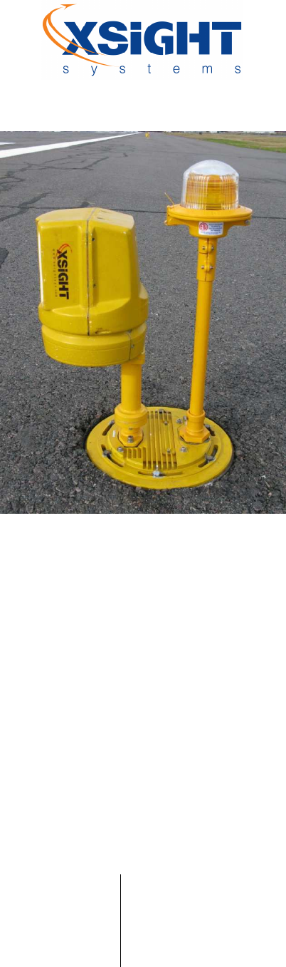
Figure 2: Sensor installed next to an edge light ....................................................... 19
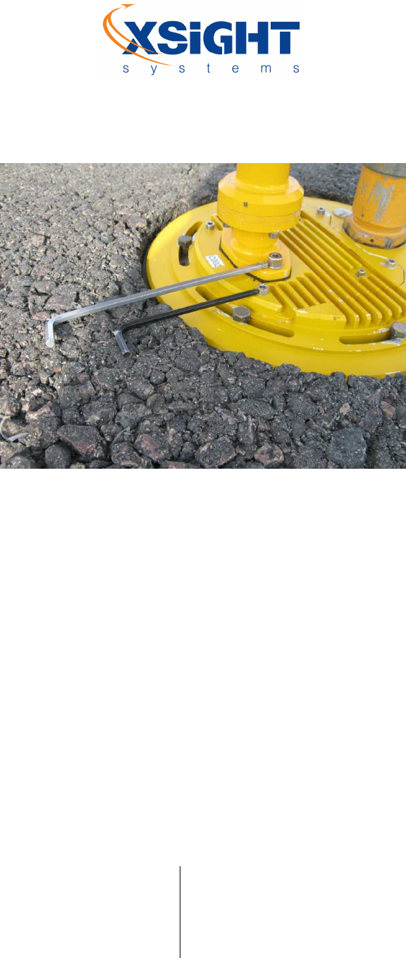
Figure 3: M6 and M8 wrenches for fastening upper and lower unit screws .................. 20
Figure 4: Dedicated CCR configuration ................................................................... 22
Figure 5: Combined power supply .......................................................................... 23
Figure 6: Separate power supply ........................................................................... 24
Figure 7: Communication network – A ring on each side of the runway ...................... 26
Figure 8: Communication network - interlaced topology ........................................... 27
Figure 9: Field patch panel ................................................................................... 28
Figure 10: SDU upper unit front view ..................................................................... 30
Figure 11: SDU upper unit rear view ...................................................................... 31
Figure 12: CCD camera components (Front View) .................................................... 33
Figure 13: CCD camera components (Side View) ..................................................... 34
Figure 14: SDU lower unit in canister ..................................................................... 37
Figure 15: Lower unit module top plate .................................................................. 38
Figure 16: Lower unit module components (rear View) ............................................. 39
Figure 17: SBC with carrier board .......................................................................... 40
Figure 18: Power supply ....................................................................................... 43
Figure 19: Power supply panel .............................................................................. 44
Figure 20: 12'' Canister cover screw holes .............................................................. 46
Figure 21: Lower unit’s connector panel ................................................................. 48
Figure 22: Lower unit's four screws ....................................................................... 49
Figure 23: Correct placement of magnet tool .......................................................... 51

Xsight Proprietary Information / Secret Commercial Information
Xsight
Systems
11 Haavoda St., Bellers House,
Rosh-Haayin, Israel 48017
Tel: +972-3-9102562 Fax: +972-3-9030590
www.xsightsys.com
One Post Office Square, 30th Floor,
Boston, Massachusetts 02109
Tel.781-330-8466 US-sales@xsightsys.com
Figure 24: Magnet tool ......................................................................................... 51
O-Level Tester Test Information ............................................................................ 52
Figure 25: Upper unit sliding into the lower unit connector housing............................ 55
Figure 26: Upper unit installation .......................................................................... 56
Figure 27: Sensor installed on a lower unit with screws tightened .............................. 57
Figure 28: Installation process .............................................................................. 58
Figure 29: Standard ACC server ............................................................................ 61

Xsight Proprietary Information / Secret Commercial Information
Xsight
Systems
11 Haavoda St., Bellers House,
Rosh-Haayin, Israel 48017
Tel: +972-3-9102562 Fax: +972-3-9030590
www.xsightsys.com
One Post Office Square, 30th Floor,
Boston, Massachusetts 02109
Tel.781-330-8466 US-sales@xsightsys.com
FCC STATEMENT
This equipment has been tested and found to comply with the limits for a Class B digital device, pursuant to part
15 of the FCC Rules. These limits are designed to provide reasonable protection against harmful interference in a
residential installation. This equipment generates, uses, and can radiate radio frequency energy and, if not
installed and used in accordance with the instructions, may cause harmful interference to radio communications.
However, there is no guarantee that interference will not occur in a particular installation. If this equipment does
cause harmful interference to radio or television reception, which can be determined by turning the equipment
off and on, the user is encouraged to try to correct the interference by one or more of the following measures:
Reorient or relocate the receiving antenna.
Increase the separation between the equipment and receiver.
Connect the equipment into an outlet on a circuit different from that to which the receiver is
connected.
Consult the dealer or an experienced radio/TV technician for help.
Caution: It is the responsibility of the installer to ensure that when using the outdoor antenna kits
in the United States (or where FCC rules apply), only those antennas certified with the
product are used. The use of any antenna other than those certified with the product is
expressly forbidden in accordance to FCC rules CFR47 part 15.204. The installer should
configure the output power level of antennas, according to country regulations and per
antenna type.
Caution: Outdoor units and antennas should be installed ONLY by experienced installation
professionals who are familiar with local building and safety codes and, wherever
applicable, are licensed by the appropriate government regulatory authorities. Failure to
do so may void the Xsight product warranty and may expose the end user or the service
provider to legal and financial liabilities. Xsight and its resellers or distributors are not
liable for injury, damage or violation of regulations associated with the installation of
outdoor units or antennas.

Xsight Proprietary Information / Secret Commercial Information
Xsight
Systems
11 Haavoda St., Bellers House,
Rosh-Haayin, Israel 48017
Tel: +972-3-9102562 Fax: +972-3-9030590
www.xsightsys.com
One Post Office Square, 30th Floor,
Boston, Massachusetts 02109
Tel.781-330-8466 US-sales@xsightsys.com
PREFACE
About This Manual
This User Manual contains information on installing the Xsight FODetect®. This manual is intended for FODetect®
system installers.
Finding Your Way in This Manual
This manual is logically divided into chapters according to topics:
Chapter 1 - Introduction
Chapter 2 – FODetect® Parts and Installation Tools
Chapter 3 – Power Requirements
Chapter 4 – Data Communication Network (LAN) Requirements
Chapter 5 – Upper Unit Components
Chapter 6 – Lower Unit Components
Chapter 7 – Pre-Installation Procedures
Chapter 8 – Installing the Power Supply
Chapter 9 – Installing the Lower Unit Top-Plate (Canister Cover)
Chapter 10 – Installing the Lower Unit
Chapter 11 – Testing the Lower Unit
Chapter 12 – Installing the Upper Unit
Chapter 13 – Computer Subsystem
Chapter 14 – Safety Instructions

Xsight Proprietary Information / Secret Commercial Information
Xsight
Systems
11 Haavoda St., Bellers House,
Rosh-Haayin, Israel 48017
Tel: +972-3-9102562 Fax: +972-3-9030590
www.xsightsys.com
One Post Office Square, 30th Floor,
Boston, Massachusetts 02109
Tel.781-330-8466 US-sales@xsightsys.com
Appendix A – Power Supply Mechanical Drawing
Appendix B – Lower Unit Mechanical Drawing
Related Manuals
FODetect® System Description
FODetect® System Operator Manual.
FODetect® System Maintenance Manual
SDU O-Level User Guide
Acronyms
The acronyms below are used in this document:
ACC Analysis and Control Center
ATC
Air Traffic Control/Controller
BIT Built In Test
CCR Constant Current Regulator
ATC
Air Traffic Control
EPU Environmental Protection Unit
FAA Federal Aviation Administration
FAT
Factory Acceptance
Test
FOD Foreign Object Debris / Damage
GUI Graphic User Interface
HMI
Human Machine Interface

Xsight Proprietary Information / Secret Commercial Information
Xsight
Systems
11 Haavoda St., Bellers House,
Rosh-Haayin, Israel 48017
Tel: +972-3-9102562 Fax: +972-3-9030590
www.xsightsys.com
One Post Office Square, 30th Floor,
Boston, Massachusetts 02109
Tel.781-330-8466 US-sales@xsightsys.com
MCU Micro Controller Unit
NIR
Near Infra Red
PDU Power Distribution Unit
SBC Single Board Computer
SDU
Surface
Detection Unit
SOC System Operator Console

Xsight Proprietary Information / Secret Commercial Information
Xsight
Systems
11 Haavoda St., Bellers House,
Rosh-Haayin, Israel 48017
Tel: +972-3-9102562 Fax: +972-3-9030590
www.xsightsys.com
One Post Office Square, 30th Floor,
Boston, Massachusetts 02109
Tel.781-330-8466 US-sales@xsightsys.com
Chapter 1 Introduction
1.1 FODetect® System Overview
Xsight's FODetect® (Foreign Object Debris Detect) system provides continuous monitoring of airport runways for
foreign object debris (FOD), facilitating rapid detection and removal of FOD in all weather conditions. Runway
FOD has resulted in significant damage to aircraft that has cost the aviation industry internationally $13 billion per
year in direct plus indirect costs. FOD has also been implicated in airplane crashes that resulted in death and
injury to aircraft personnel and passengers.
The FODetect® system’s is based on Surface Detection Units (SDUs) distributed along both sides of the airport
runway. Xsight's proprietary SDU software integrates leading image processing technology with Millimeter-Wave-
Radar sensors in order to detect any change along the ground. The SDUs communicate with a central computer
server (ACC) via a robust LAN connection based on standard technologies such as copper and fiber. Based on the
FOD data received from the SDUs, the ACC sends alerts about suspected FOD to the system operator console
(SOC). SOC operators can view real-time images and video of the FOD as well as operate SDU sensors to get a
clearer visual on the detected FOD. Personnel sent to remove a FOD are guided directly to the FOD location by a
laser beam that is emitted from the SDU all the way to the detected FOD.
FODetect® insures near-immediate detection of FOD through its multi-sensor system. Each SDU scans its own
predetermined region between airplane movements, (typically, within 90 seconds) enabling the entire runway to
be scanned in parallel during that time. In addition to FOD detection, SDU cameras provide air and ground
controllers with an added benefit of round-the-clock general surveillance capabilities.
The SDUs are integrated into an existing runway lighting infrastructure. Each SDU is installed separately utilizing
an existing runway/taxiway edge light canister, and using the existing mechanical infrastructure and cable ducts
to the extent possible. This minimizes installation costs and time while achieving the optimal location for runway
surveillance Systems that are installed several hundreds of meters from the runway are likely to provide relatively
poor detection capabilities due to increased atmospheric interference and signal attenuation.
The SDUs are spaced along the runway to allow overlapping coverage by adjacent SDUs. This achieves system
redundancy, ensuring comprehensive coverage even in the case of individual SDU failure. Using multiple sources
of information in the FOD Alert algorithm also reduces the rate of false alarms and increases the real FOD

Xsight Proprietary Information / Secret Commercial Information
Xsight
Systems
11 Haavoda St., Bellers House,
Rosh-Haayin, Israel 48017
Tel: +972-3-9102562 Fax: +972-3-9030590
www.xsightsys.com
One Post Office Square, 30th Floor,
Boston, Massachusetts 02109
Tel.781-330-8466 US-sales@xsightsys.com
detection rate. SDUs are installed on both sides of the runway to insure they are not obstructed by the runway’s
transverse slope, designed to facilitate water drainage.
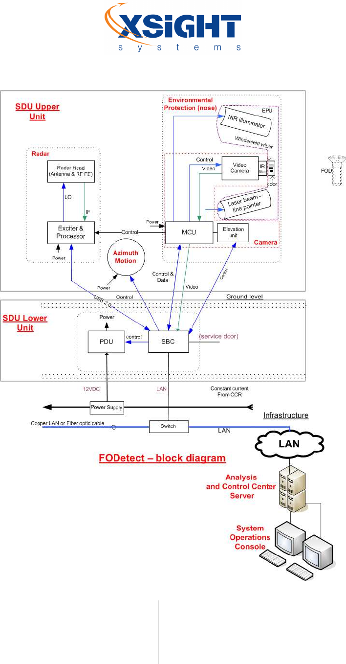
1.2 System Components
The FODetect® system hardware equipment comprises the following components:
Surface Detection Unit
SDU upper unit
• Radar head
• Video camera
• NIR illuminator
• Laser beam line pointer
• Door and windshield wiper control unit
SDU lower unit
• Video grabbing
• Copper / fiber optic LAN connection
• High performance, general purpose CPU
• Serial ports and USB interface
• Power management, command & control
Operator Interface and Network Server
Analysis and Control Center (ACC)
System Operator Console (SOC)
Power and Communications Infrastructure
Power
• Constant current regulator (CCR)
• Line series power supply
Communications network
• Router
• Switch

Xsight Proprietary Information / Secret Commercial Information
Xsight
Systems
11 Haavoda St., Bellers House,
Rosh-Haayin, Israel 48017
Tel: +972-3-9102562 Fax: +972-3-9030590
www.xsightsys.com
One Post Office Square, 30th Floor,
Boston, Massachusetts 02109
Tel.781-330-8466 US-sales@xsightsys.com
• Cables
Xsight Proprietary Information / Secret Commercial Information
Xsight
Systems
11 Haavoda St., Bellers House,
Rosh-Haayin, Israel 48017
Tel: +972-3-9102562 Fax: +972-3-9030590
www.xsightsys.com
One Post Office Square, 30th Floor,
Boston, Massachusetts 02109
Tel.781-330-8466 US-sales@xsightsys.com
Figure 1: FODetect® system components

Xsight Proprietary Information / Secret Commercial Information
Xsight
Systems
11 Haavoda St., Bellers House,
Rosh-Haayin, Israel 48017
Tel: +972-3-9102562 Fax: +972-3-9030590
www.xsightsys.com
One Post Office Square, 30th Floor,
Boston, Massachusetts 02109
Tel.781-330-8466 US-sales@xsightsys.com
1.3 About the Installation Process
FODetect® offers a multi-sensor deployment that is integrated into an existing runway lighting infrastructure.
Each sensor is installed separately utilizing an existing runway/taxiway edge light canister. Installation and testing
of the power and communications infrastructure should be completed before installing the SDUs.

Xsight Proprietary Information / Secret Commercial Information
Xsight
Systems
11 Haavoda St., Bellers House,
Rosh-Haayin, Israel 48017
Tel: +972-3-9102562 Fax: +972-3-9030590
www.xsightsys.com
One Post Office Square, 30th Floor,
Boston, Massachusetts 02109
Tel.781-330-8466 US-sales@xsightsys.com
Chapter 2 FODetect® Parts and Installation Tools
The following parts and tools are used during the installation of each SDU:
2.1 Part List for One (1) SDU
Description
Quantity
Xsight Part # (P/N)
Remarks / details
Lower Unit Top
-
Plate (Canister Cover)
SDU
-
600/P12,
Lower
unit top-plate (Canister
Cover)-, 12"
1
XT2012000100
The canister cover, as well as the
necessary screws and washers may
vary depending on the existing
canister layout. In this document, a
standard FAA type canister is
described.
Seal, Oring,
ID227.97X5.33 S70, 2-
373
1
XT2040000015
Hex Head Cap Screw
St.St. 3/8-16 x 1 3/8
6
MS
-
35307
-
363
Flat Washer
3/8
.
-
DIN 125A
6
Spring Washer
3/8
-
DIN 127
6
Upper Cover Dummy
Kit Upper Cover,
Dummy, for Comp V7
1
XT0020000104
In cases when the canister cover is
installed before the lower units
(processors) have been supplied, the
lower unit hole must be covered
with a protective cover. When the
lower unit is supplied it replaces the
protective cover.
Upper Cover, Dummy,
for Comp V7
1
XT2012000164

Xsight Proprietary Information / Secret Commercial Information
Xsight
Systems
11 Haavoda St., Bellers House,
Rosh-Haayin, Israel 48017
Tel: +972-3-9102562 Fax: +972-3-9030590
www.xsightsys.com
One Post Office Square, 30th Floor,
Boston, Massachusetts 02109
Tel.781-330-8466 US-sales@xsightsys.com
Screw Socket Head Cap
M6X16 DIN 912
4
XT4050000121
Washer, Flat M6 DIN
433
4
XT4050000122
Washer, Helical Spring
M6 DIN 127A
4
XT4050000123
Power supply
1
XT1050000027
Power supply type may vary
depending on the runway
configuration and infrastructure.
There are 2 types of power supplies
– with or without an embedded
transformer / isolator. See
Infrastructure Requirement
Document.
Lower unit computer,
ver 7 (Processor)
1
XT0030000011
For fiber optic config.
Upper Unit (Sensor)
Upper unit, ver 6.2
(sensor)
1
XT0020000061
Sensor mounting
screws - Socket Head
Cap Screw M8 x 20 DIN
912
2
Flat
w
asher
M8
DIN
433
2
Helical
s
pring
l
ock
washer M8 DIN 127A
2
Edge light flange
1
Associated screws
Grounding bolt and
wire
Xsight Proprietary Information / Secret Commercial Information
Xsight
Systems
11 Haavoda St., Bellers House,
Rosh-Haayin, Israel 48017
Tel: +972-3-9102562 Fax: +972-3-9030590
www.xsightsys.com
One Post Office Square, 30th Floor,
Boston, Massachusetts 02109
Tel.781-330-8466 US-sales@xsightsys.com
2.2 List of Tools Used During Installation
Description
Use
Remarks / details
M6 wrench
Lower unit
fastening screws
3/8 open wrench
Canister cover fastening screw
s
Air
-
pressured
wrench
(not
mandatory)
Canister cover fastening screws
M8 wrench
Upper unit
fastening screws
Xsight magnet tool
Used during installation to
control and reset the unit
Electrical insulation
tape
Tool to unscrew the edge light
Tool for the
grounding bolt
and wire
Lower unit
removal
handle
Used to lift the lower unit
OLT
A portable unit that runs
diagnostic checks on the SDU
components.
Optional
Xsight Proprietary Information / Secret Commercial Information
Xsight
Systems
11 Haavoda St., Bellers House,
Rosh-Haayin, Israel 48017
Tel: +972-3-9102562 Fax: +972-3-9030590
www.xsightsys.com
One Post Office Square, 30th Floor,
Boston, Massachusetts 02109
Tel.781-330-8466 US-sales@xsightsys.com
Figure 2: Sensor installed next to an edge light
Xsight Proprietary Information / Secret Commercial Information
Xsight
Systems
11 Haavoda St., Bellers House,
Rosh-Haayin, Israel 48017
Tel: +972-3-9102562 Fax: +972-3-9030590
www.xsightsys.com
One Post Office Square, 30th Floor,
Boston, Massachusetts 02109
Tel.781-330-8466 US-sales@xsightsys.com
Figure 3: M6 and M8 wrenches for fastening upper and lower unit screws

Xsight Proprietary Information / Secret Commercial Information
Xsight
Systems
11 Haavoda St., Bellers House,
Rosh-Haayin, Israel 48017
Tel: +972-3-9102562 Fax: +972-3-9030590
www.xsightsys.com
One Post Office Square, 30th Floor,
Boston, Massachusetts 02109
Tel.781-330-8466 US-sales@xsightsys.com
Chapter 3 Power Requirements
3.1 ACC and SOC Power Requirements
In addition to the SDUs, the system includes an Analysis and Control Center (ACC) server and at least one System
Operator Console (SOC). A recommended configuration includes 2 ACC modules, in order to provide redundancy
and failover between the two servers. In some installations, two SOC computers are also used – one in the
operations tower by the operations staff, and one in the Air Traffic Control (ATC) by the ATC. The power
requirement for the ACC server is AC 500W for the computer and 45W for a standard monitor. The power
requirement for the SOC workstations is AC 400W for the computer and 60W for a 22” monitor.
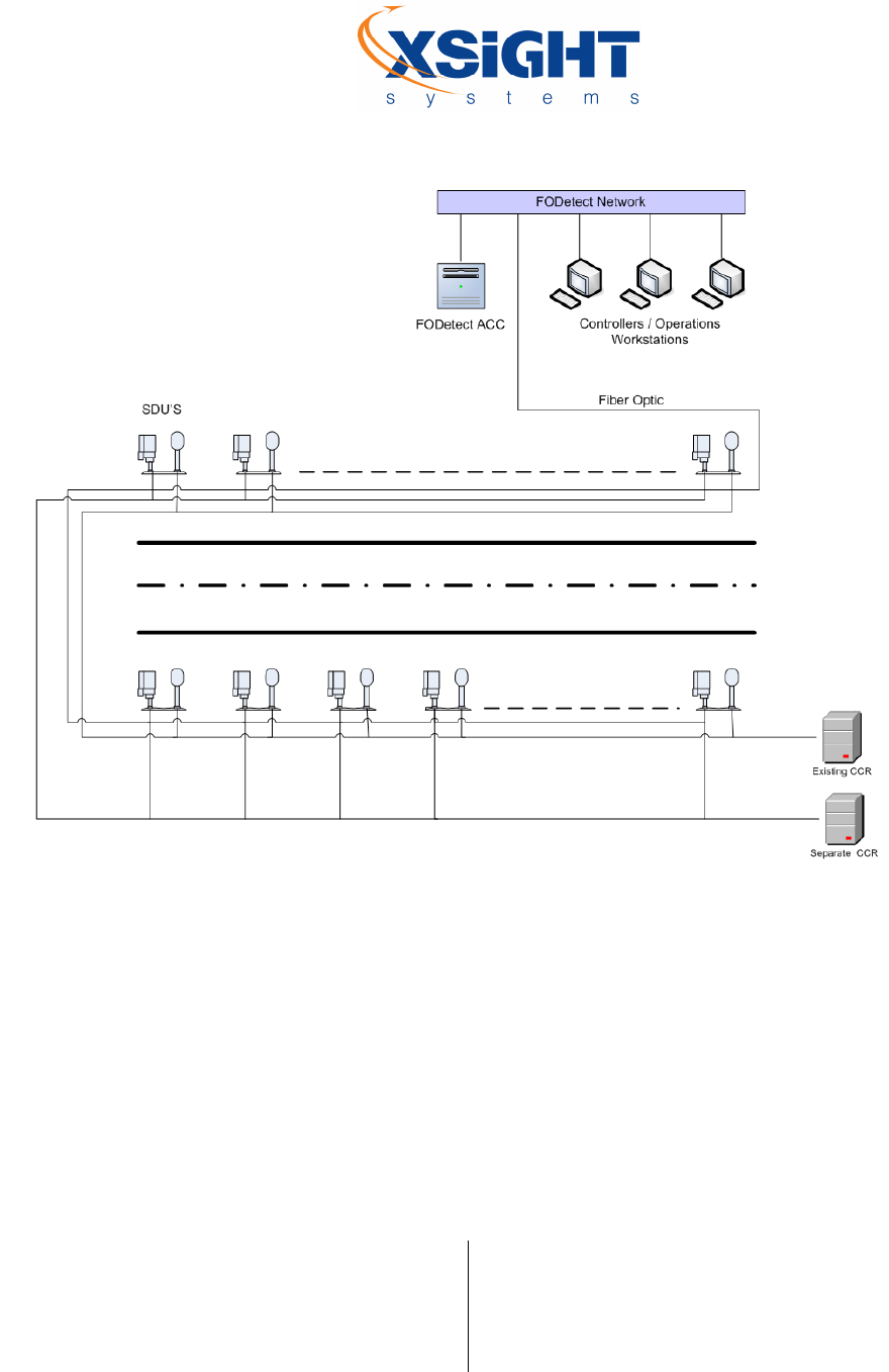
3.2 Input Power – Using a Constant Current Regulator
Power is generally supplied by constant current from dedicated CCRs (Constant Current Regulators) placed in the
airport’s existing CCR vaults. The SDUs are connected to the CCRs using separate power cables that are placed in
existing power sleeves and ducts. One 7500 watt CCR generally suffices for each runway. If there are more than
100 SDUs on the runway, a 10,000 watt CCR should be used.
An alternative option is to use the runway lighting’s existing CCR to power the SDUs by giving each SDU control
over the runway edge light next to which it is installed.
Xsight Proprietary Information / Secret Commercial Information
Xsight
Systems
11 Haavoda St., Bellers House,
Rosh-Haayin, Israel 48017
Tel: +972-3-9102562 Fax: +972-3-9030590
www.xsightsys.com
One Post Office Square, 30th Floor,
Boston, Massachusetts 02109
Tel.781-330-8466 US-sales@xsightsys.com
Figure 4: Dedicated CCR configuration
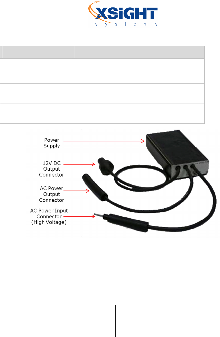
3.3 Power Supply
The power supplied by the CCR is stepped down to the required voltage by a standard 150-200 watt transformer,
which is fed by the primary CCR series line. It is then converted from alternating current (AC) to direct current
(DC) by a power supply unit (P/N – XT1050000027) located in each canister next to the SDU. When a power
supply with an embedded transformer is used (P/N – XT1050000021), the combined power supply is connected to
the primary CCR series line.
Xsight Proprietary Information / Secret Commercial Information
Xsight
Systems
11 Haavoda St., Bellers House,
Rosh-Haayin, Israel 48017
Tel: +972-3-9102562 Fax: +972-3-9030590
www.xsightsys.com
One Post Office Square, 30th Floor,
Boston, Massachusetts 02109
Tel.781-330-8466 US-sales@xsightsys.com
Parameter Specification
Input 6A-6.6A series line through a L830 transformer
Output 12VDC, 60 watt power
Environmental
Conditions
-
40°
+65°, water sealed, IP68 (conforms to FAA Advisory
Circular (AC) regulations)
Dimensions
245X52.5X124 mm
(with embedded transformer) /
184X52.5X124 mm (without transformer)
Figure 5: Combined power supply
Xsight Proprietary Information / Secret Commercial Information
Xsight
Systems
11 Haavoda St., Bellers House,
Rosh-Haayin, Israel 48017
Tel: +972-3-9102562 Fax: +972-3-9030590
www.xsightsys.com
One Post Office Square, 30th Floor,
Boston, Massachusetts 02109
Tel.781-330-8466 US-sales@xsightsys.com
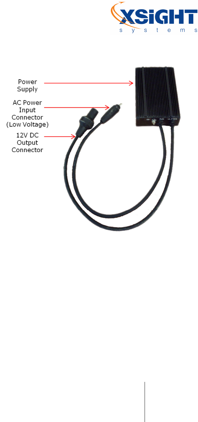
Figure 6: Separate power supply