Xsight Systems FODE6MWR FODetect System with Radar in 76-77 GHz Band User Manual Part II
Xsight Systems Inc. FODetect System with Radar in 76-77 GHz Band Part II
Contents
- 1. User Manual (Part I)
- 2. User Manual (Part II)
- 3. User Manual (Part III)
User Manual (Part II)

Xsight Proprietary Information / Secret Commercial Information
Xsight
Systems
11 Haavoda St., Bellers House,
Rosh-Haayin, Israel 48017
Tel: +972-3-9102562 Fax: +972-3-9030590
www.xsightsys.com
One Post Office Square, 30th Floor,
Boston, Massachusetts 02109
Tel.781-330-8466 US-sales@xsightsys.com
Chapter 4 Data Communication Network (LAN) Requirements
4.1 Communication Network Overview
The SDUs connect to the central computer system via a TCP/IP LAN connection based on standard technologies
such as copper or fiber. Xsight recommends using self healing rings (a daisy chain is also acceptable, although less
reliable). The advantage of a self healing ring is that while in normal use, traffic is dispatched in the direction of
the shortest path towards the server, in the event of the loss of a link, or of an entire station, the two nearest
surviving stations "loop back" their ends of the ring. In this way, traffic can still travel to all surviving parts of the
ring, even if it has to travel "the long way round".
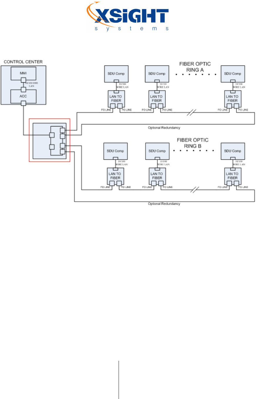
Alternative options include splitting the power and network into two rings each with independent power sources.
The SDUs are alternately connected to each of the two power sources so that if one power source completely
fails, the runway will continue being monitored by the SDUs that are powered by the working power source (with
a distance of 120/100 meters between SDUs instead of 60/50 meters). Another possibility is to create two
separate rings, one on each side of the runway, so that no cable duct crossing the runway is necessary (See Figure
7 below).
Xsight Proprietary Information / Secret Commercial Information
Xsight
Systems
11 Haavoda St., Bellers House,
Rosh-Haayin, Israel 48017
Tel: +972-3-9102562 Fax: +972-3-9030590
www.xsightsys.com
One Post Office Square, 30th Floor,
Boston, Massachusetts 02109
Tel.781-330-8466 US-sales@xsightsys.com
Figure 7: Communication network – A ring on each side of the runway
Xsight Proprietary Information / Secret Commercial Information
Xsight
Systems
11 Haavoda St., Bellers House,
Rosh-Haayin, Israel 48017
Tel: +972-3-9102562 Fax: +972-3-9030590
www.xsightsys.com
One Post Office Square, 30th Floor,
Boston, Massachusetts 02109
Tel.781-330-8466 US-sales@xsightsys.com
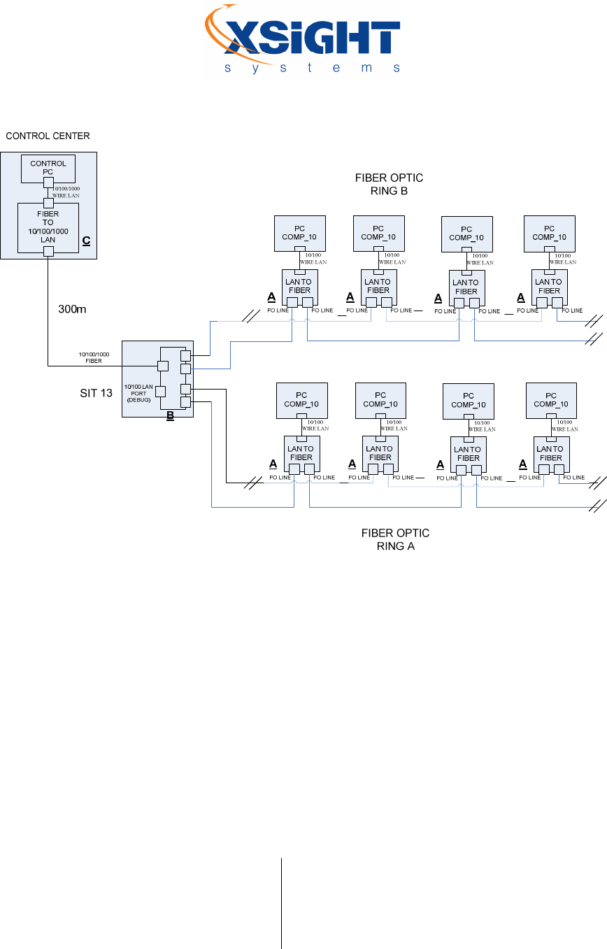
Figure 8: Communication network - interlaced topology
4.2 Switch and Cables
The communication switch is responsible for the following processes:
Converting between SM (Single Mode) and MM (Multi Mode).
Rebuilding a spanning tree of the network when an SDU in the chain is breaking the chain. When
the SDU is communicating again, for example after a maintenance action, the switch will re-build
the spanning tree.
The communication cable used to connect the SDUs on the runway to the communication switch is generally fiber
optic due to the long distance. Depending on the distance, either Single-Mode (SM) Fiber or Multi-Mode (MM)
fiber will be used. Between the SDUs, MM is normally used, while the SDU connector is Huber Suhner ODC4
outdoor connector.

Xsight Proprietary Information / Secret Commercial Information
Xsight
Systems
11 Haavoda St., Bellers House,
Rosh-Haayin, Israel 48017
Tel: +972-3-9102562 Fax: +972-3-9030590
www.xsightsys.com
One Post Office Square, 30th Floor,
Boston, Massachusetts 02109
Tel.781-330-8466 US-sales@xsightsys.com
4.3 Connection from the Field to the ACC Server
A field patch panel is used at the point where both runway loops meet to connect the field with the ACC. The field
patch panel collects the data from the runway units and transfers it to the ACC. It includes active equipment such
as switches and transmission equipment, and passive equipment such as splice boxes. Street cabinets are used for
hosting the field networking equipment and patch panels.
Figure 9: Field patch panel

Xsight Proprietary Information / Secret Commercial Information
Xsight
Systems
11 Haavoda St., Bellers House,
Rosh-Haayin, Israel 48017
Tel: +972-3-9102562 Fax: +972-3-9030590
www.xsightsys.com
One Post Office Square, 30th Floor,
Boston, Massachusetts 02109
Tel.781-330-8466 US-sales@xsightsys.com
Chapter 5 Upper Unit Components
The SDU upper unit combines a day/night Vision sensor with a FMCW W-band Radar sensor. The Radar sensor
provides complementary performance even when the Vision sensor has limitations during low visibility
conditions.
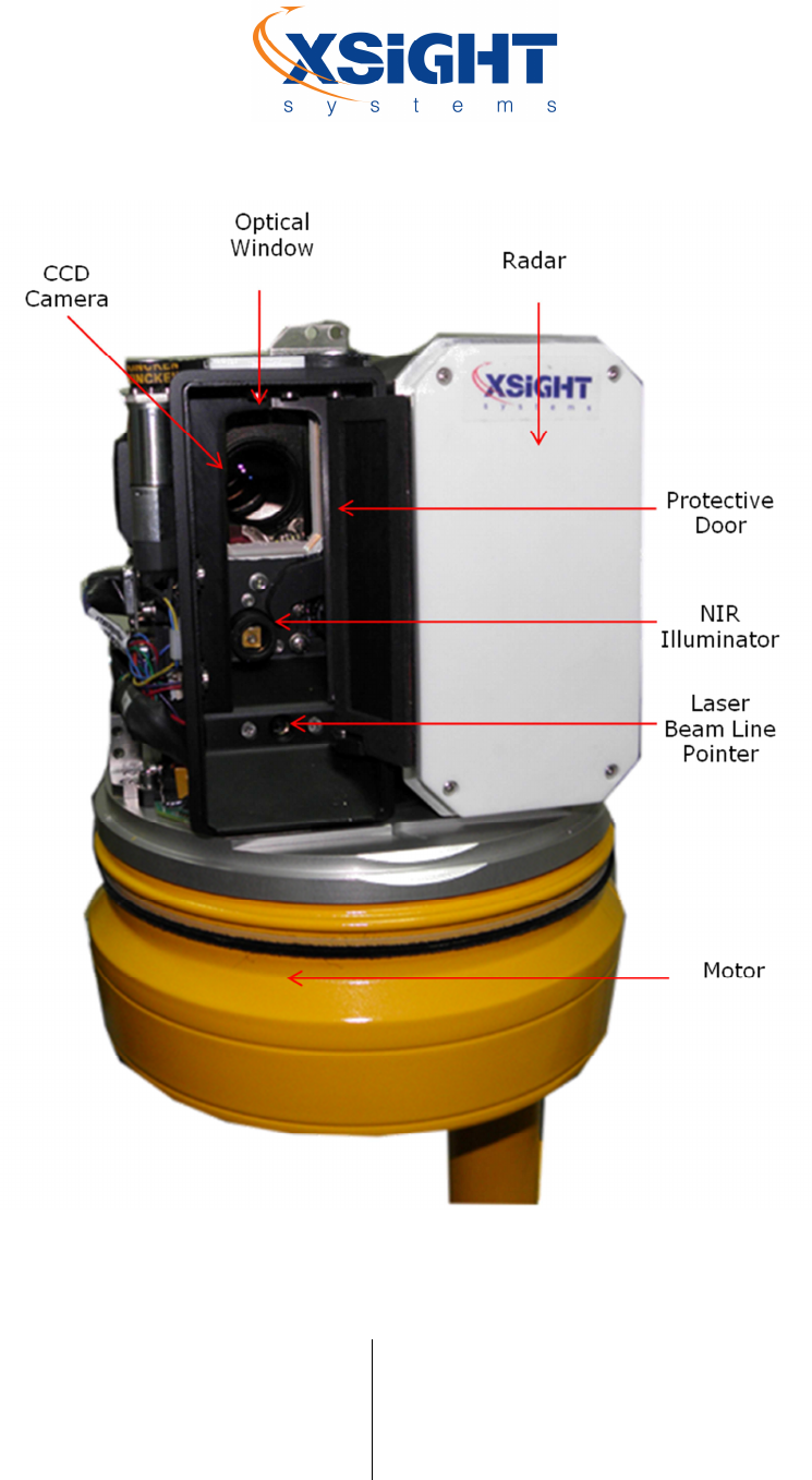
The SDU upper unit includes the following components:
Millimetric Wave Radar (MMWR) Head
Video Camera
NIR Illuminator
Laser Beam Line Pointer
Door and Windshield Wiper Control Unit
Xsight Proprietary Information / Secret Commercial Information
Xsight
Systems
11 Haavoda St., Bellers House,
Rosh-Haayin, Israel 48017
Tel: +972-3-9102562 Fax: +972-3-9030590
www.xsightsys.com
One Post Office Square, 30th Floor,
Boston, Massachusetts 02109
Tel.781-330-8466 US-sales@xsightsys.com
Figure 10: SDU upper unit front view
Xsight Proprietary Information / Secret Commercial Information
Xsight
Systems
11 Haavoda St., Bellers House,
Rosh-Haayin, Israel 48017
Tel: +972-3-9102562 Fax: +972-3-9030590
www.xsightsys.com
One Post Office Square, 30th Floor,
Boston, Massachusetts 02109
Tel.781-330-8466 US-sales@xsightsys.com
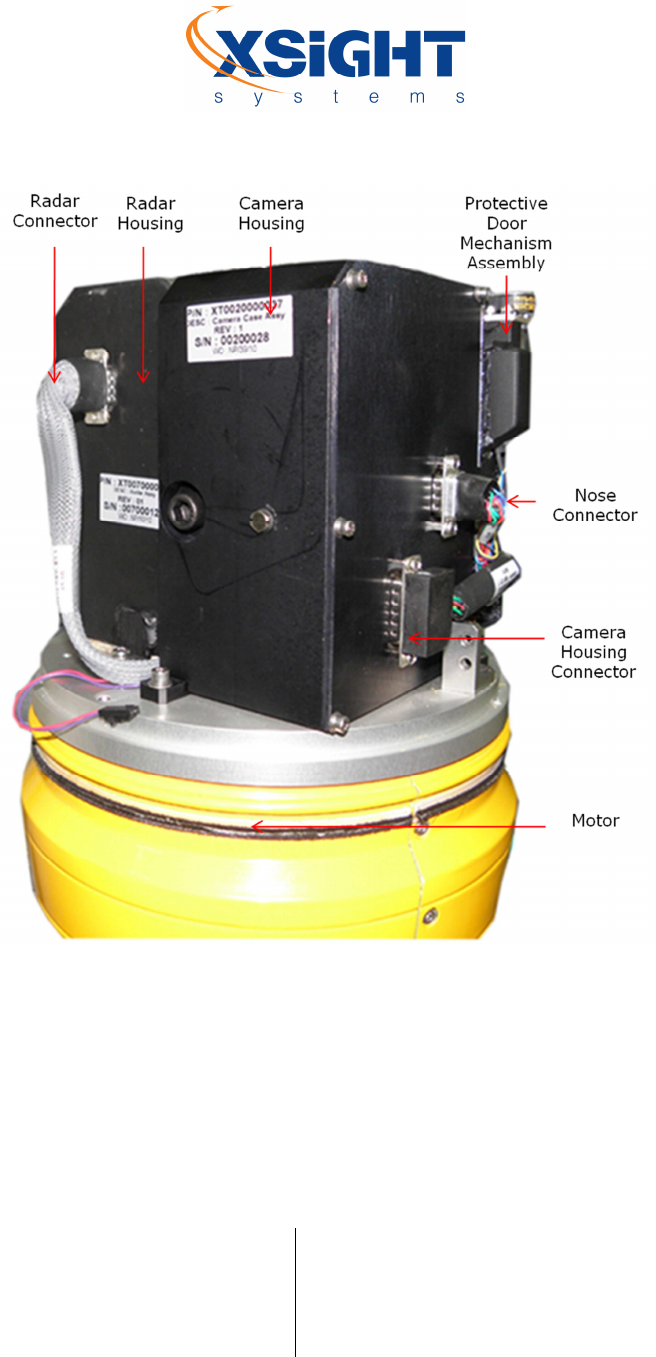
Figure 11: SDU upper unit rear view
5.1 Charge-Coupled Device (CCD) Camera
The Vision sensor camera uses image analysis software that compares images of the monitored area to previous
images stored in memory, to determine the presence of a foreign object on the runway. Parameters including
number of inspections per second number of images stored in memory, shutter speed and zoom are preset by
Xsight. The camera can also be manually operated by operators, using the SOC.
Xsight Proprietary Information / Secret Commercial Information
Xsight
Systems
11 Haavoda St., Bellers House,
Rosh-Haayin, Israel 48017
Tel: +972-3-9102562 Fax: +972-3-9030590
www.xsightsys.com
One Post Office Square, 30th Floor,
Boston, Massachusetts 02109
Tel.781-330-8466 US-sales@xsightsys.com
The FODetect® camera offers 24/7 day-night functionality. As light diminishes below a certain level, the camera
automatically switches to night mode to make use of near infrared (IR) light to deliver high-quality, black and
white images.
Near-infrared light, which spans from 700 nanometers (nm) up to about 1000 nm, is not visible to the human eye
but it can be sensed by the camera’s sensor. During the day, a day and night camera uses an IR-cut filter, that
filters out IR light so that it does not distort the colors of images as the human eye sees them. When the camera is
in night (black and white) mode, the IR-cut filter is removed, allowing the camera’s light sensitivity to reach down
to 0.001 lux (measure of light intensity) or lower.
5.1.1 Specifications
SDU
–
Optical Component
Imager
Color / Monochrome CCD
Horizontal FOV 2.6° (maximum zoom)
Synchronizing System Internal
Minimal Illumination 0.05 lux - 0.7 lux
S/N Ratio 50 dB
NIR Beam
Square Beam
8°
-
12°
NIR Beam Power 2 W
NIR Beam Wavelength 808nm
NIR Laser Safety Class 4
5.1.2 NIR Illuminator
An NIR illuminator within the camera housing that provides near-infrared light is used in conjunction with the
camera to further enhance the camera’s ability to produce high-quality video in lowlight or nighttime conditions.
This illuminator can be activated manually by an operator using the system operator console (SOC).
Xsight Proprietary Information / Secret Commercial Information
Xsight
Systems
11 Haavoda St., Bellers House,
Rosh-Haayin, Israel 48017
Tel: +972-3-9102562 Fax: +972-3-9030590
www.xsightsys.com
One Post Office Square, 30th Floor,
Boston, Massachusetts 02109
Tel.781-330-8466 US-sales@xsightsys.com
5.1.3 Door and Windshield Wiper Control Unit
A windshield wiper within the camera housing can be operated manually, from the system operator console
(SOC), in order to clean the camera optical window. An operator can also activate a water spray pump located
within the camera housing.
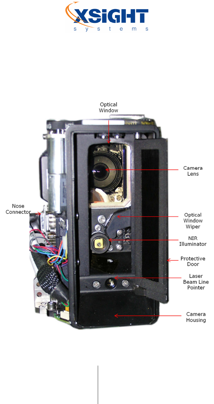
Figure 12: CCD camera components (Front View)
Xsight Proprietary Information / Secret Commercial Information
Xsight
Systems
11 Haavoda St., Bellers House,
Rosh-Haayin, Israel 48017
Tel: +972-3-9102562 Fax: +972-3-9030590
www.xsightsys.com
One Post Office Square, 30th Floor,
Boston, Massachusetts 02109
Tel.781-330-8466 US-sales@xsightsys.com
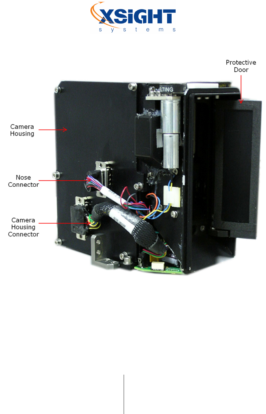
Figure 13: CCD camera components (Side View)
5.2 Radar Component
A Frequency Modulated Continuous Wave (FMCW) W-band radar, gimbaled together with the camera, performs
independent monitoring, in order to achieve full performance at all times.
Through frequency modulation, the systematic variation of the transmitted frequency, it becomes possible to use
a FMCW radar system to measure a target’s range. By measuring the frequency difference of the transmission
and reception return signals, the range can be estimated.

Xsight Proprietary Information / Secret Commercial Information
Xsight
Systems
11 Haavoda St., Bellers House,
Rosh-Haayin, Israel 48017
Tel: +972-3-9102562 Fax: +972-3-9030590
www.xsightsys.com
One Post Office Square, 30th Floor,
Boston, Massachusetts 02109
Tel.781-330-8466 US-sales@xsightsys.com
The FODetect® radar component is managed by a DSP-based processor, providing advanced processing features.
It is optimized for high probability-of-detection (Pd) and low false-alarm-rate (FAR) of extremely low radar-cross-
section (RCS) targets.
It can be customized to meet the customer’s specific requirements including:
Tailoring the MWR antennas to meet a required beam shape.
Controlling (via a management port) many of the waveform parameters (such as chirp
bandwidth, time, slope, PRF etc) for meeting a required performance envelope (Various target
RCS, various ranges, various Doppler resolutions, various Pd/FAR, etc.).
Shaping the physical size and form-factor to fit a variety of carrying platforms (Mobile, airborne
etc.).
SDU-Radar Component
Transmitter Characteristics
Frequency
76.5 ± 0.5 GHz
Transmit Wave Form
LFMCW
Peak Power
14 dBm
Ramp Length 500 microseconds
Instantaneous Bandwidth 1 GHz
Receiver Characteristics
Dynamic Range
80 dB
Noise Figure
12
dB
Antenna Characteristics
Elevation Beam Width
4°

Xsight Proprietary Information / Secret Commercial Information
Xsight
Systems
11 Haavoda St., Bellers House,
Rosh-Haayin, Israel 48017
Tel: +972-3-9102562 Fax: +972-3-9030590
www.xsightsys.com
One Post Office Square, 30th Floor,
Boston, Massachusetts 02109
Tel.781-330-8466 US-sales@xsightsys.com
Azimuth Beam Width 4°
Gain 32 dBi
5.3 Laser Beam Line Pointer
The SDU includes a built-in laser pointer for highlighting FOD locations for efficient removal at night. The laser
pointer is manually activated by an operator using the system operator console (SOC).
Line Laser Pointer
Line Laser Pointer Power
8mW
Line Angle
56°
Line Laser Pointer Safety Class 1
Line Laser Pointer Wavelength 650nm (red)
Xsight Proprietary Information / Secret Commercial Information
Xsight
Systems
11 Haavoda St., Bellers House,
Rosh-Haayin, Israel 48017
Tel: +972-3-9102562 Fax: +972-3-9030590
www.xsightsys.com
One Post Office Square, 30th Floor,
Boston, Massachusetts 02109
Tel.781-330-8466 US-sales@xsightsys.com
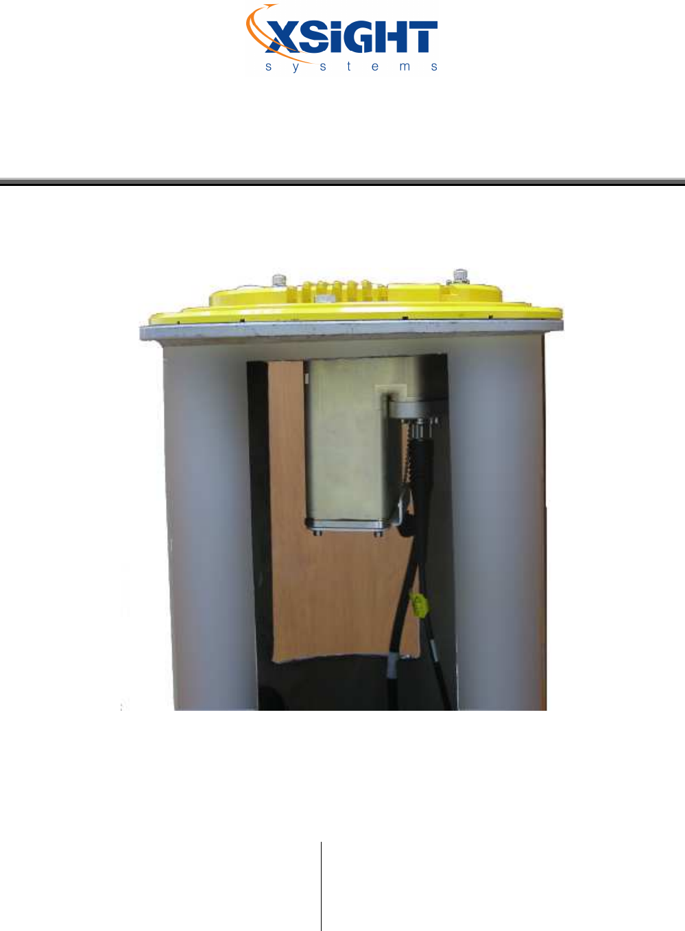
Chapter 6 Lower Unit Components
All FOD detection data received by the upper unit camera and radar is processed locally by internal processors in
each individual SDU, so that the main server does not need to process high volumes of data simultaneously. While
the sensor is scanning for FOD it only informs the server of its operating status.
Figure 14: SDU lower unit in canister
Xsight Proprietary Information / Secret Commercial Information
Xsight
Systems
11 Haavoda St., Bellers House,
Rosh-Haayin, Israel 48017
Tel: +972-3-9102562 Fax: +972-3-9030590
www.xsightsys.com
One Post Office Square, 30th Floor,
Boston, Massachusetts 02109
Tel.781-330-8466 US-sales@xsightsys.com
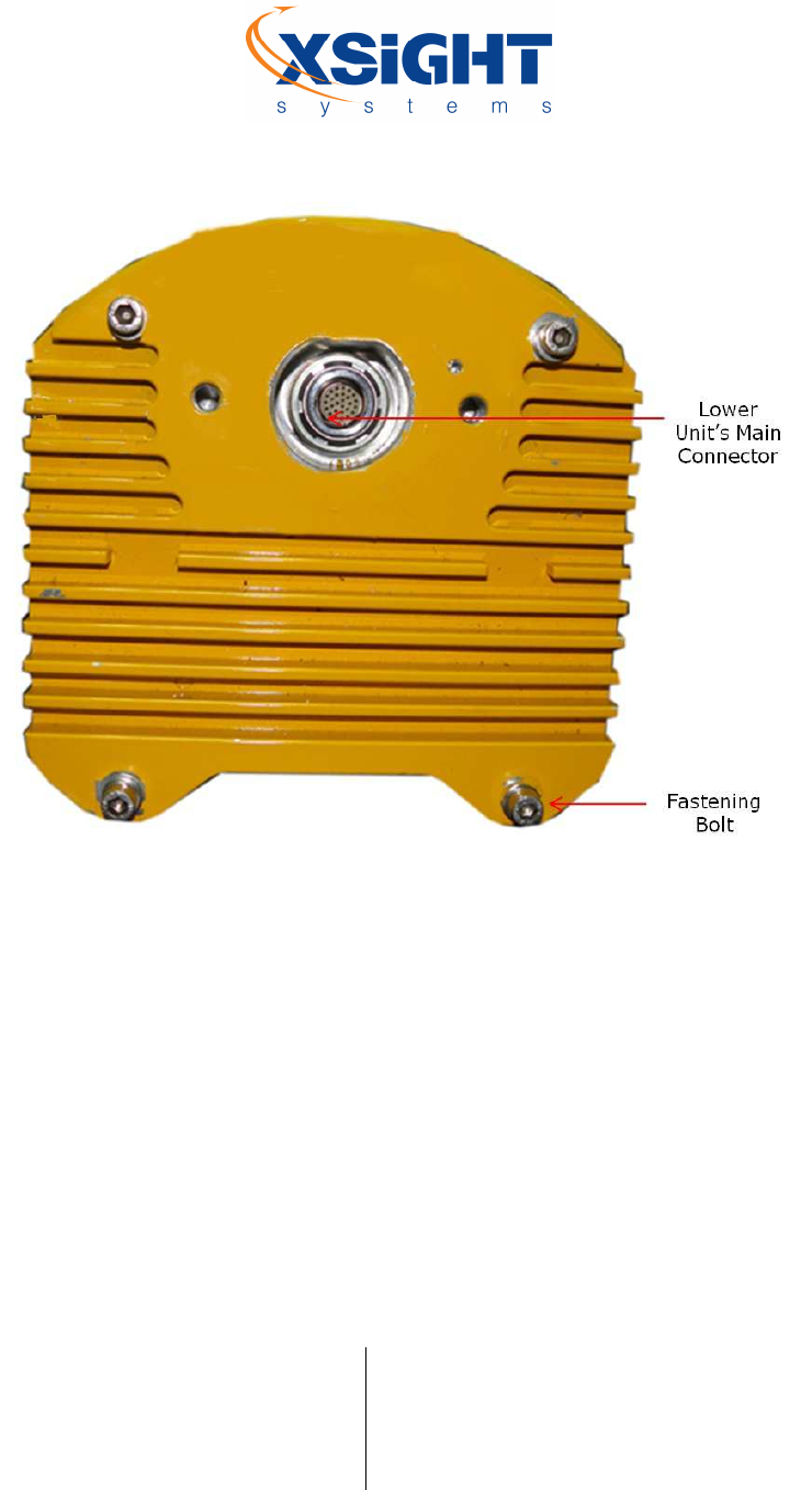
Figure 15: Lower unit module top plate
Xsight Proprietary Information / Secret Commercial Information
Xsight
Systems
11 Haavoda St., Bellers House,
Rosh-Haayin, Israel 48017
Tel: +972-3-9102562 Fax: +972-3-9030590
www.xsightsys.com
One Post Office Square, 30th Floor,
Boston, Massachusetts 02109
Tel.781-330-8466 US-sales@xsightsys.com
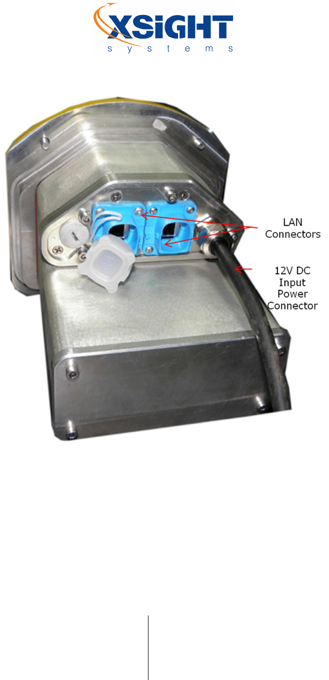
Figure 16: Lower unit module components (rear View)
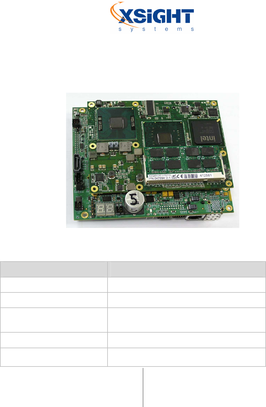
6.1 Processor
The FODetect® processor uses a proprietary main board (carrier) and an off-the-shelf, high-performance
COMExpress Single Board Computer (SBC).
The processor includes the following components/
Video grabbing
Copper / Fiber optic LAN connection
Xsight Proprietary Information / Secret Commercial Information
Xsight
Systems
11 Haavoda St., Bellers House,
Rosh-Haayin, Israel 48017
Tel: +972-3-9102562 Fax: +972-3-9030590
www.xsightsys.com
One Post Office Square, 30th Floor,
Boston, Massachusetts 02109
Tel.781-330-8466 US-sales@xsightsys.com
High performance, general purpose CPU
Serial ports and USB interface
Power management, command & control
Figure 17: SBC with carrier board
6.2 SBC Specifications
Component
Specification
Backplane
Active carrier board
Power Supply
Single input voltage
Processor
Intel® Core™ 2 Duo SU9300 1.2GHz with 3
-
MByte L2
cache
Memory (RAM)
2 memory cards, 2GB each
Ports
3 10/100/1000 Ethernet ports, 2 100/1000 Fiber ports, 3
USB, 1 VGA, 2 S-video, 1 RS485, 1 RS232, 1 Audio line out,

Xsight Proprietary Information / Secret Commercial Information
Xsight
Systems
11 Haavoda St., Bellers House,
Rosh-Haayin, Israel 48017
Tel: +972-3-9102562 Fax: +972-3-9030590
www.xsightsys.com
One Post Office Square, 30th Floor,
Boston, Massachusetts 02109
Tel.781-330-8466 US-sales@xsightsys.com
Component Specification
1 Mic in
Chipset
Graphics and Memory Controller Hub (GMCH) Intel® GS45
Intel® I/O Controller Hub 82801IUX-SFF (ICH9M-SFF)

Xsight Proprietary Information / Secret Commercial Information
Xsight
Systems
11 Haavoda St., Bellers House,
Rosh-Haayin, Israel 48017
Tel: +972-3-9102562 Fax: +972-3-9030590
www.xsightsys.com
One Post Office Square, 30th Floor,
Boston, Massachusetts 02109
Tel.781-330-8466 US-sales@xsightsys.com
Chapter 7 Pre-Installation Procedures
As part of the boot process of the lower unit, if needed it downloads software from the server. Then, it burns this
software into the various SDU elements, such as PDU, Frame grabber, MCU etc. If there is a power failure during
this burn, at certain points of time, these units might fail.
Therefore, during installation period, when the power is not stable and might fail, the ACC should be configured
to "installation mode" in which the "USYS server" (the ACC service that updates the SDUs with the latest software
packages) is turned off.
Xsight Proprietary Information / Secret Commercial Information
Xsight
Systems
11 Haavoda St., Bellers House,
Rosh-Haayin, Israel 48017
Tel: +972-3-9102562 Fax: +972-3-9030590
www.xsightsys.com
One Post Office Square, 30th Floor,
Boston, Massachusetts 02109
Tel.781-330-8466 US-sales@xsightsys.com
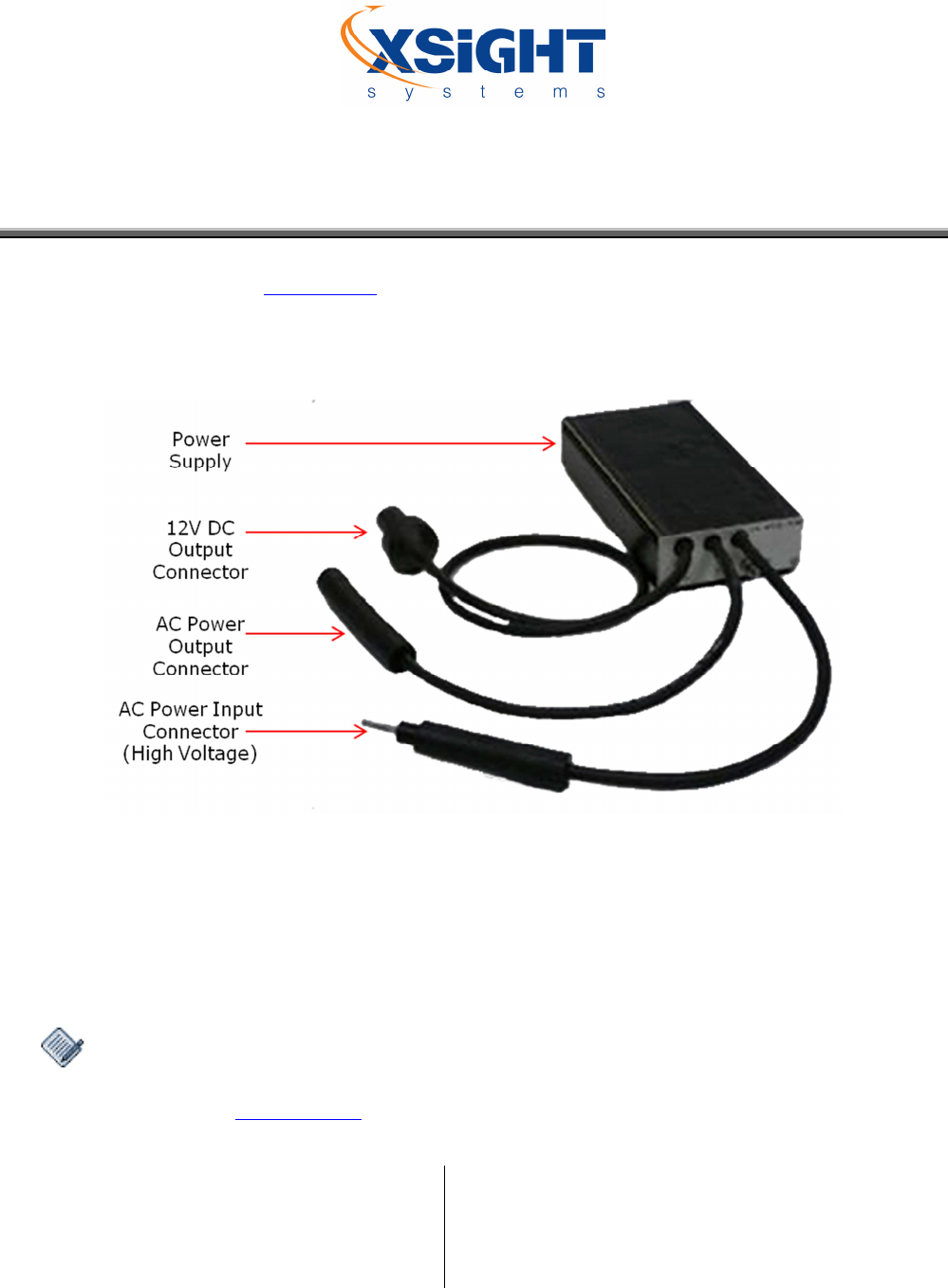
Chapter 8 Installing the Power Supply
It is recommended to install the power supply in the canister during the infrastructure work, prior to the
installation of the system. See “Power Supply” in the “Power Requirements” chapter for power supply
specifications.
Figure 18: Power supply
To install the power supply:
1. Connect a grounding cable to its place on the power supply panel, and tighten the screw.
2. Connect the grounding cable to a grounding fastener on the inside of the canister.
3. Connect the power supply input connector to the CCR series line connectors, and locate it on the
bottom of the canister.
If using a power supply without an embedded transformer, connect the power supply
(P/N – XT1050000027) to a standard 200Watt transformer that is connected to the CCR
series. See “Power Supply” in the “Power Requirements” chapter for further information.
Xsight Proprietary Information / Secret Commercial Information
Xsight
Systems
11 Haavoda St., Bellers House,
Rosh-Haayin, Israel 48017
Tel: +972-3-9102562 Fax: +972-3-9030590
www.xsightsys.com
One Post Office Square, 30th Floor,
Boston, Massachusetts 02109
Tel.781-330-8466 US-sales@xsightsys.com
4. Connect the power supply output cable to the lower unit input power connector. The unit
supplies 12VDC power to the SDU system (up to 5.5A). Apply the yellow insulation tape to
connection points to achieve a weatherproof and airtight seal.
Make sure to completely connect the cable to the power connector, leaving absolutely
no gap, to prevent the power supply from overheating and burning out.
If the lower unit is not installed as part of the power supply installation, place a cap on
the secondary connector and secure it with insulation tape.
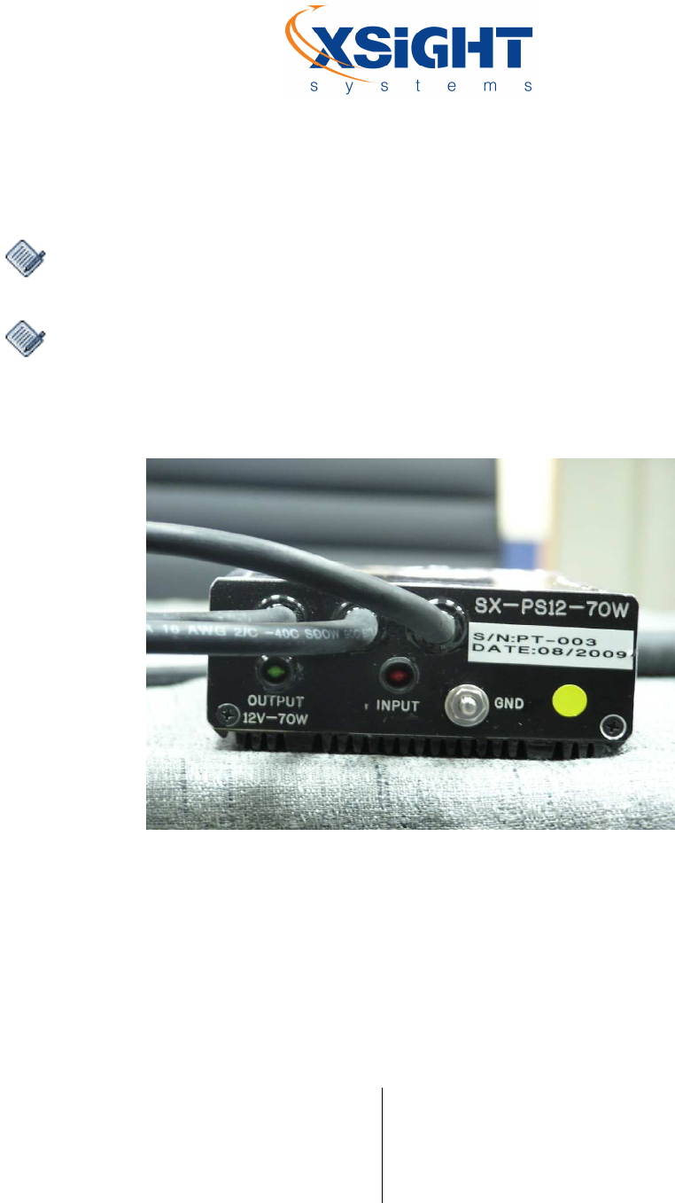
5. When applying CCR power, the "Input" LED on the power supply panel will be lit if the input
power is valid. See the power supply panel in the following image:
Figure 19: Power supply panel